US9344827B2 - Method and apparatus for audio output, and electronic device - Google Patents
Method and apparatus for audio output, and electronic device Download PDFInfo
- Publication number
- US9344827B2 US9344827B2 US14/404,369 US201414404369A US9344827B2 US 9344827 B2 US9344827 B2 US 9344827B2 US 201414404369 A US201414404369 A US 201414404369A US 9344827 B2 US9344827 B2 US 9344827B2
- Authority
- US
- United States
- Prior art keywords
- speaker
- output
- electronic device
- audio data
- stereo
- Prior art date
- Legal status (The legal status is an assumption and is not a legal conclusion. Google has not performed a legal analysis and makes no representation as to the accuracy of the status listed.)
- Expired - Fee Related, expires
Links
Images


Classifications
-
- H—ELECTRICITY
- H04—ELECTRIC COMMUNICATION TECHNIQUE
- H04S—STEREOPHONIC SYSTEMS
- H04S7/00—Indicating arrangements; Control arrangements, e.g. balance control
-
- H—ELECTRICITY
- H04—ELECTRIC COMMUNICATION TECHNIQUE
- H04M—TELEPHONIC COMMUNICATION
- H04M1/00—Substation equipment, e.g. for use by subscribers
- H04M1/72—Mobile telephones; Cordless telephones, i.e. devices for establishing wireless links to base stations without route selection
- H04M1/724—User interfaces specially adapted for cordless or mobile telephones
- H04M1/72403—User interfaces specially adapted for cordless or mobile telephones with means for local support of applications that increase the functionality
- H04M1/72442—User interfaces specially adapted for cordless or mobile telephones with means for local support of applications that increase the functionality for playing music files
-
- H04M1/72558—
-
- H—ELECTRICITY
- H04—ELECTRIC COMMUNICATION TECHNIQUE
- H04R—LOUDSPEAKERS, MICROPHONES, GRAMOPHONE PICK-UPS OR LIKE ACOUSTIC ELECTROMECHANICAL TRANSDUCERS; DEAF-AID SETS; PUBLIC ADDRESS SYSTEMS
- H04R3/00—Circuits for transducers, loudspeakers or microphones
- H04R3/12—Circuits for transducers, loudspeakers or microphones for distributing signals to two or more loudspeakers
-
- H—ELECTRICITY
- H04—ELECTRIC COMMUNICATION TECHNIQUE
- H04R—LOUDSPEAKERS, MICROPHONES, GRAMOPHONE PICK-UPS OR LIKE ACOUSTIC ELECTROMECHANICAL TRANSDUCERS; DEAF-AID SETS; PUBLIC ADDRESS SYSTEMS
- H04R5/00—Stereophonic arrangements
- H04R5/02—Spatial or constructional arrangements of loudspeakers
-
- H—ELECTRICITY
- H04—ELECTRIC COMMUNICATION TECHNIQUE
- H04S—STEREOPHONIC SYSTEMS
- H04S1/00—Two-channel systems
- H04S1/002—Non-adaptive circuits, e.g. manually adjustable or static, for enhancing the sound image or the spatial distribution
-
- H—ELECTRICITY
- H04—ELECTRIC COMMUNICATION TECHNIQUE
- H04M—TELEPHONIC COMMUNICATION
- H04M1/00—Substation equipment, e.g. for use by subscribers
- H04M1/02—Constructional features of telephone sets
- H04M1/03—Constructional features of telephone transmitters or receivers, e.g. telephone hand-sets
-
- H—ELECTRICITY
- H04—ELECTRIC COMMUNICATION TECHNIQUE
- H04M—TELEPHONIC COMMUNICATION
- H04M2250/00—Details of telephonic subscriber devices
- H04M2250/12—Details of telephonic subscriber devices including a sensor for measuring a physical value, e.g. temperature or motion
-
- H—ELECTRICITY
- H04—ELECTRIC COMMUNICATION TECHNIQUE
- H04R—LOUDSPEAKERS, MICROPHONES, GRAMOPHONE PICK-UPS OR LIKE ACOUSTIC ELECTROMECHANICAL TRANSDUCERS; DEAF-AID SETS; PUBLIC ADDRESS SYSTEMS
- H04R2420/00—Details of connection covered by H04R, not provided for in its groups
- H04R2420/03—Connection circuits to selectively connect loudspeakers or headphones to amplifiers
-
- H—ELECTRICITY
- H04—ELECTRIC COMMUNICATION TECHNIQUE
- H04R—LOUDSPEAKERS, MICROPHONES, GRAMOPHONE PICK-UPS OR LIKE ACOUSTIC ELECTROMECHANICAL TRANSDUCERS; DEAF-AID SETS; PUBLIC ADDRESS SYSTEMS
- H04R2499/00—Aspects covered by H04R or H04S not otherwise provided for in their subgroups
- H04R2499/10—General applications
- H04R2499/11—Transducers incorporated or for use in hand-held devices, e.g. mobile phones, PDA's, camera's
Definitions
- the present invention relates to electronic devices, and particularly, to a method and an apparatus for audio output, and an electronic device.
- One of the functions is to play audio data such as music or speeches through a stereo, which uses two or more independent sound effect channels and appears on a pair of speakers (e.g., horns) arranged symmetrically.
- the sound generated in such a method is kept natural and melodious in various directions.
- a mobile phone having a stereo function only obtains the stereo output effect at a specific position (e.g., the horizontal position), and once the mobile phone is deviated from the specific position such as being rotated to another position (e.g., the vertical position), the output of the speakers is no longer stereophonic since the position of the speakers is changed.
- a specific position e.g., the horizontal position
- another position e.g., the vertical position
- the embodiments of the present invention provide a method and an apparatus for audio output, and an electronic device, so that the stereo output effect can be obtained when the electronic device is under a speaker output mode, regardless of whether the electronic device is placed in a horizontal position or a vertical position.
- a method for audio output is provided, which is applicable to an electronic device, wherein the electronic device includes a first speaker, a second speaker, a third speaker and a fourth speaker, the first speaker and the second speaker disposed at the left and right sides of the electronic device placed in a horizontal state, respectively, and the third speaker and the fourth speaker disposed at the left and right sides of the electronic device placed in a vertical state, respectively, the method including:
- a stereo output and/or a bass output of audio data to be outputted to a speaker (or speakers) corresponding to the placement state of the electronic device, and outputting the audio data in the form of stereo output and/or bass output through the speaker(s) corresponding to the placement state of the electronic device.
- a first stereo output of the audio data is switched to the first speaker, and a second stereo output of the audio data is switched to the second speaker, so as to output the audio data in the form of stereo output through the first speaker and the second speaker.
- a bass output of the audio data is switched to the third speaker and/or the fourth speaker, so as to output the audio data in the form of bass output through the third speaker and/or the fourth speaker.
- a first stereo output of the audio data is switched to the third speaker, and a second stereo output of the audio data is switched to the fourth speaker, so as to output the audio data in the form of stereo output through the third speaker and the fourth speaker.
- a bass output of the audio data is switched to the first speaker and/or the second speaker, so as to output the audio data in the form of bass output through the first speaker and/or the second speaker.
- the method further includes:
- the method further includes:
- the method further includes:
- an apparatus for audio output which is included in an electronic device, wherein the electronic device further includes a first speaker, a second speaker, a third speaker and a fourth speaker, the first speaker and the second speaker disposed at the left and right sides of the electronic device placed in a horizontal state, respectively, and the third speaker and the fourth speaker disposed at the left and right sides of the electronic device placed in a vertical state, respectively, the apparatus including:
- a detection unit configured to detect a placement state of the electronic device when the electronic device is under a speaker output mode
- a switching unit configured to switch a stereo output and/or a bass output of audio data to be outputted to a speaker (or speakers) corresponding to the placement state of the electronic device, according to the placement state of the electronic device detected by the detection unit;
- an output unit configured to output the audio data in the form of stereo output and/or bass output through the speaker(s) corresponding to the placement state of the electronic device.
- the switching unit switches a first stereo output of the audio data to the first speaker, and switches a second stereo output of the audio data to the second speaker;
- the output unit outputs the audio data in the form of stereo output through the first speaker and the second speaker.
- the switching unit switches a bass output of the audio data to the third speaker and/or the fourth speaker;
- the output unit outputs the audio data in the form of bass output through the third speaker and/or the fourth speaker.
- the switching unit switches a first stereo output of the audio data to the third speaker, and switches a second stereo output of the audio data to the fourth speaker;
- the output unit outputs the audio data in the form of stereo output through the third speaker and the fourth speaker.
- the switching unit switches a bass output of the audio data to the first speaker and/or the second speaker;
- the output unit outputs the audio data in the form of bass output through the first speaker and/or the second speaker.
- the apparatus further includes:
- control unit configured to adjust audio parameters according to the placement state of the electronic device detected by the detection unit, and determine the stereo output and/or the bass output of the audio data according to the adjusted audio parameters.
- the switching unit switches a handset output of acquired audio data to the first speaker, the second speaker, the third speaker or the fourth speaker;
- the output unit outputs the acquired audio data through the first speaker, the second speaker, the third speaker or the fourth speaker.
- the detection unit detects distances from the first speaker, the second speaker, the third speaker and the fourth speaker to an ear respectively, and determine a speaker closest to the ear;
- the switching unit switches a handset output of acquired audio data to the speaker closest to the ear;
- the output unit outputs the acquired audio data through the speaker closest to the ear.
- an electronic device wherein the electronic device includes:
- a first speaker, a second speaker, a third speaker and a fourth speaker the first speaker and the second speaker disposed at the left and right sides of the electronic device placed in a horizontal state, respectively, and the third speaker and the fourth speaker disposed at the left and right sides of the electronic device placed in a vertical state, respectively; and the apparatus for audio output aforementioned.
- the first speaker and the second speaker are disposed in the same horizontal line at the left and right sides of the electronic device placed in the horizontal state, respectively, and the third speaker and the fourth speaker are disposed in the same horizontal line at the left and right sides of the electronic device placed in the vertical state, respectively.
- the first speaker, the second speaker, the third speaker and/or the fourth speaker include(s) a plurality of speakers.
- the stereo output effect can be obtained by setting the speakers at the four sides of the electronic device, respectively, and starting different speakers when the electronic device is at different positions, once the stereo play function is activated, i.e., the electronic device is under the speaker output mode, regardless of whether the electronic device is at the horizontal position or the vertical position.
- FIG. 1 is a flowchart of an implementation of a method for audio output in Embodiment 1 of the present invention
- FIGS. 2A, 2B and 2C are similar schematic diagrams where an electronic device in Embodiment 1 is placed in a horizontal state;
- FIG. 3 is a schematic diagram where an electronic device in Embodiment 1 is placed in a vertical state
- FIG. 4 is a flowchart of another implementation of a method for audio output in Embodiment 1 of the present invention.
- FIG. 5 is a schematic structure diagram of an apparatus for audio output in Embodiment 2 of the present invention.
- FIG. 6 is a schematic diagram of an implementation of an apparatus for audio output in Embodiment 2 of the present invention.
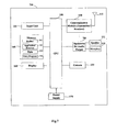
- FIG. 7 is a schematic block diagram of a system structure of an electronic device in Embodiment 3 of the present invention.
- the interchangeable terms “electronic device” and “electronic apparatus” include a portable radio communication device.
- portable radio communication device which is hereinafter referred to as “mobile radio terminal”, “portable electronic apparatus”, or “portable communication apparatus”, includes all devices such as mobile phone, pager, communication apparatus, electronic organizer, personal digital assistant (PDA), smart phone, portable communication apparatus, etc.
- PDA personal digital assistant
- the embodiments of the present invention are mainly described with respect to a portable electronic apparatus in the form of a mobile phone (also referred to as “cellular phone”).
- a mobile phone also referred to as “cellular phone”.
- the present invention is not limited to the case of the mobile phone and it may relate to any type of appropriate electronic device, such as media player, gaming device, PDA, computer, digital camera, etc.
- Embodiment 1 of the present invention provides a method for audio output applicable to an electronic device, wherein the electronic device includes a first speaker, a second speaker, a third speaker and a fourth speaker, the first speaker and the second speaker disposed at the left and right sides of the electronic device placed in a horizontal state, respectively, and the third speaker and the fourth speaker disposed at the left and right sides of the electronic device placed in a vertical state, respectively.
- FIG. 1 is a flowchart of an implementation of a method for audio output in Embodiment 1 of the present invention. As illustrated in FIG. 1 , the method including:
- Step 101 detecting a placement state of the electronic device when the electronic device is under a speaker output mode
- Step 102 switching, according to the placement state of the electronic device, a stereo output and/or a bass output of audio data to be outputted to a speaker (or speakers) corresponding to the placement state of the electronic device, and outputting the audio data in the form of stereo output and/or bass output through the speaker(s) corresponding to the placement state of the electronic device.
- the audio data to be outputted may be a music file pre-stored in the electronic device, an audio file in the Internet, etc., but the embodiment is not limited thereto.
- the electronic device may be a smart phone, a tablet PC, etc., but the present invention is not limited thereto.
- the electronic device includes a first speaker, a second speaker, a third speaker and a fourth speaker.
- the embodiment is just described taking that the first speaker and the second speaker are disposed at the left and right sides of the electronic device placed in the horizontal state, respectively, and the third speaker and the fourth speaker are disposed at the left and right sides of the electronic device placed in the vertical state, respectively as an example. But the embodiment is not limited thereto.
- the user may start the speaker output mode by operating the audio play button (or the virtual key).
- the placement state of the electronic device may be detected in step 101 of the embodiment, including detecting whether the electronic device is in the horizontal state or the vertical state. The detection may be realized through existing means, and herein is not described.
- the horizontal state and the vertical state are not absolute. For example, when it is detected that the vertical sides of the electronic device are deviated from the gravity center line for a predetermined angle, the electronic device is still deemed as being in the horizontal state.
- the predetermined angle may be set upon demand, and usually less than 45 degrees.
- the horizontal sides of the electronic device are two sides perpendicular to the gravity center line when the electronic device is in the horizontal state
- the vertical sides of the electronic device are two sides parallel with the gravity center line when the electronic device is in the horizontal state.
- the embodiment is not limited to starting to detect the placement state of the electronic device only when the electronic device is under the speaker output mode.
- the detection of the placement state of the electronic device applied to the rotation of the display screen may be used, e.g., once the user activates the automatic rotation function, the detection of the placement state of the electronic device is started.
- the rotation of the display screen is controlled according to the detection result.
- the detection result of the placement state of the electronic device is used for the speaker switching.
- step 102 when the electronic device is placed in the horizontal state, the first stereo output of the audio data is switched to the first speaker, and the second stereo output of the audio data is switched to the second speaker, so as to output the audio data in the form of stereo output through the first speaker and the second speaker. Since the first speaker and the second speaker are disposed at the left and right sides of the electronic device placed in the horizontal state, the distances from the two speakers to corresponding ears of the user are similar to each other in that state, thus the user can obtain the stereo effect.
- the first stereo may be an output of a stereo left channel of the audio data
- the second stereo may be an output of a stereo right channel of the audio data
- the embodiment is not limited thereto.
- the first stereo may be an output of the stereo right channel of the audio data
- the second stereo may be an output of the stereo left channel of the audio data.
- the electronic device 10 illustrated in FIG. 2A is taken as an example.
- the electronic device is placed in the horizontal state.
- the speaker output mode is started.
- the speakers A 1 and B 1 e.g., sometimes referred to, without limitation, as the first and second speakers, respectively
- the speakers A 1 and B 1 at the left and right sides of the electronic device placed in the horizontal state are activated, so that the user can obtain the stereo effect of the audio data.
- first speaker A 1 , second speaker B 1 , third speaker A 2 , and/or fourth speaker B 2 may be composed of more than one speaker, the two illustrated examples being as two speakers shown in FIG. 2B or as four speakers shown in FIG. 2C , but the number may be three, five or any other number of speakers, as may be desired.
- the method may further include: switching the bass output of the audio data to the third speaker and/or the fourth speaker (e.g., sometimes referred to as speakers A 2 and B 2 , respectively), and outputting the audio data in the form of bass output through the third speaker and/or the fourth speaker.
- the bass effect can be obtained in addition to the stereo effect of the audio data, thereby further improving the user experience.
- the electronic device illustrated in FIG. 2A is still taken as an example.
- the audio data is outputted in the form of stereo output through the speakers A 1 and B 1 , it also can be outputted in the form of bass output through the speaker(s) A 2 and/or B 2 .
- the user obtains the bass effect in addition to the stereo effect of the audio data.
- step 102 when the electronic device 10 is placed in the vertical state, the first stereo output of the audio data is switched to the third speaker, e.g., A 2 , and the second stereo output of the audio data is switched to the fourth speaker, e.g., B 2 , so as to output the audio data in the form of stereo output through the third speaker and the fourth speaker. Since the third speaker and the fourth speaker are disposed at the left and right sides of the electronic device placed in the vertical state, the distances from the two speakers to corresponding ears of the user are similar to each other in that state, thus the user can obtain the stereo effect.
- the third speaker and the fourth speaker are disposed at the left and right sides of the electronic device placed in the vertical state, the distances from the two speakers to corresponding ears of the user are similar to each other in that state, thus the user can obtain the stereo effect.
- the electronic device 10 illustrated in FIG. 3 is taken as an example.
- the electronic device is placed in the vertical state.
- the speaker output mode is started.
- the speakers A 2 and B 2 at the left and right sides of the electronic device placed in the vertical state are activated, so that the user can obtain the stereo effect of the audio data.
- the method may further include: switching the bass output of the audio data to the first speaker, e.g., A 1 , and/or the second speaker, e.g., B 1 , and outputting the audio data in the form of bass output through the first speaker and/or the second speaker.
- the bass effect can be obtained in addition to the stereo effect of the audio data, thereby further improving the user experience.
- the electronic device 10 illustrated in FIG. 3 is still taken as an example.
- the audio data is outputted in the form of stereo output through the speakers A 2 and B 2 , it also can be outputted in the form of bass output through the speaker(s) A 1 and/or B 1 .
- the user obtains the bass effect in addition to the stereo effect of the audio data.
- the stereo output effect can be obtained by setting the speakers at the four sides of the electronic device, respectively, and starting different speakers when the electronic device is at different positions (the term positions sometimes may be referred to equivalently as states, orientations or positional relationships of the respective speakers, for example), once the stereo play function is activated, i.e., the electronic device is under the speaker output mode, regardless of whether the electronic device is at the horizontal position or the vertical position.
- the method may further include:
- the audio parameters are those used for adjusting the audio effect, including, but not limited to, the frequency parameter.
- Adjusting the audio parameters according to different placement states of the electronic device include, for example, adjusting the audio parameters to be suitable for the stereo output and/or the bass output in the vertical state when it is detected that the electronic device is placed in the vertical state, and adjusting the audio parameters to be suitable for the stereo output and/or the bass output in the horizontal state when it is detected that the electronic device is placed in the horizontal state; or adjusting different audio parameters according to the placement states of the electronic device, so as to output different stereo or bass effects when the electronic device is in different placement states.
- the audio parameters can be arbitrarily adjusted according to the actual requirement, and the embodiment is not limited thereto.
- any manner in the prior art may be adopted to adjust the stereo output and/or bass output of the audio data according to different audio parameters, and herein is omitted.
- the method may further include:
- the audio data may be the sound of the opposite side in the conversation acquired by listening to the phone call, an audio file pre-stored by the electronic device, an audio file acquired through a speech transmission, etc., and the embodiment is not limited thereto.
- a speaker corresponding to the handset output may be preset, for example at least one of the above four speakers.
- the audio data to be outputted is outputted under the handset output mode through the preset speaker.
- the preset speaker may be any one or several of the above four speakers, and the embodiment is not limited thereto.
- the speaker closest to the user's ear may be started by detecting the distances from various speakers to the user's ear, thereby improving the flexibility of listening to the phone call.
- the method further including:
- the detection may be performed through a distance sensor.
- distance sensors d 1 , d 2 , d 3 , d 4 may be included in the speakers (e.g., A 1 , B 1 , A 2 , B 2 ), for example, or may be one or more separate distance sensors separate from the speakers, to acquire detection information, as is illustrated, for example, in FIG. 2A .
- the detection information may be used for indicating the distance between each speaker and the ear.
- a comparison of the detection information may be made to determine which speaker is closest to a given ear of the user. After it is determined according to the comparison between/among the detection information that one of the speakers is closest to the ear, the electronic equipment switches the handset output of the acquired audio data to that speaker, and outputs the acquired audio data through that speaker.
- the electronic equipment switches to send audio data the different speaker, e.g., in a case that the user moves the electronic device.
- the distance sensor(s) may be realized through existing means, and herein is not described. The comparisons made and switching of signals mentioned may be carried out under appropriate computer program code operating via the memory 140 and CPU 100 described further below.
- FIG. 4 is a flowchart of another implementation of a method for audio output in the embodiment of the present invention.
- the implementation is just schematic, and the embodiment of the present invention is not limited thereto.
- some steps may be omitted, and some steps may be replaced by others as mentioned before, which are omitted herein.
- the method including:
- Step 401 detecting an output mode (also referred to as a play mode) of the electronic device, and performing step 402 when the electronic device is under the speaker output (or play) mode, or performing step 411 when the electronic device is under the handset output (or play) mode;
- an output mode also referred to as a play mode
- Step 402 detecting a placement state of the electronic device, and performing step 403 when the electronic device is placed in a horizontal state, or performing step 407 when the electronic device is placed in a vertical state;
- Step 403 adjusting the audio parameters into a first group of preset values
- Step 404 determining a first stereo, a second stereo and a bass output of the audio data according to the first group of audio parameters
- Step 405 switching the adjusted first stereo output of the audio data to the first speaker A 1 , and switching the adjusted second stereo output of the audio data to the second speaker B 1 ;
- Step 406 switching the adjusted bass output of the audio data to the third speaker A 2 and/or the fourth speaker B 2 ;
- steps 403 - 404 and 406 can be omitted.
- the orders of steps 405 and 406 can be exchanged, e.g., step 406 may be performed before step 405 .
- Step 407 adjusting the audio parameters into a second group of preset values
- Step 408 determining a first stereo, a second stereo and a bass output of the audio data according to the second group of audio parameters
- Step 409 switching the adjusted first stereo output of the audio data to the third speaker A 2 , and switching the adjusted second stereo output of the audio data to the fourth speaker B 2 ;
- Step 410 switching the adjusted bass output of the audio data to the first speaker A 1 and/or the second speaker B 1 ;
- steps 407 - 408 and 410 can be omitted.
- the orders of steps 409 and 410 can be exchanged, e.g., step 410 may be performed before step 409 .
- Step 411 detecting the distances from the first speaker A 1 , the second speaker B 1 , the third speaker A 2 and the fourth speaker B 2 to the ear respectively, and determining a speaker closest to the ear, for example, as is described above with respect to distance sensors d 1 -d 4 and associated operation.
- Step 412 switching a handset output of acquired audio data to the speaker closest to the ear.
- step 411 may be omitted. In that case, the handset output of the acquired audio data is switched to the preset speaker directly in step 412 .
- the first and second groups of preset values of the audio parameters may be arbitrarily set according to the actual requirement, and the embodiment is not limited thereto.
- FIG. 4 only illustrates an example where the electronic device is placed in the vertical or horizontal state, and the present invention is not limited thereto.
- the speaker switching mode in FIG. 4 is also not limited thereto.
- steps 403 , 404 , 406 ⁇ 408 and 410 ⁇ 412 for example may be omitted, and the specific implementation can be determined according to the actual condition or actual requirements, e.g., as desired or required for the current conditions or implementation.
- the stereo output effect can be obtained by setting the speakers at the four sides of the electronic device, respectively, and starting different speakers when the electronic device is at different positions (e.g., also referred to as orientations or states), once the stereo play function is activated, i.e., the electronic device is under the speaker output mode, regardless of whether the electronic device is at the horizontal position or the vertical position.
- an optimum stereo output effect can be obtained by adjusting the audio parameters.
- Embodiment 2 of the present invention further provides an audio output apparatus included in an electronic device.
- the electronic device further includes a first speaker, a second speaker, a third speaker and a fourth speaker, the first speaker and the second speaker disposed at the left and right sides of the electronic device placed in a horizontal state, respectively, and the third speaker and the fourth speaker disposed at the left and right sides of the electronic device placed in a vertical state, respectively.
- the implementation of the method may be referred to for the implementation of the apparatus, e.g., as described above with respect to the device 10 of FIGS. 1 and 2 , and the repeated parts shall not be described any further.
- FIG. 5 is a schematic structure diagram of an apparatus for audio output in Embodiment 2 of the present invention. As illustrated in FIG. 5 , the apparatus including: a detection unit 501 , a switching unit 502 and an output unit 503 , wherein,
- the detection unit 501 is configured to detect a placement state of the electronic device when the electronic device is under a speaker output mode (for example, the detection unit may include one or more conventional accelerometers or other devices and conventional circuitry, computer code in memory 140 for operating the CPU 100 , and so on, that detect orientation of the electronic device, e.g., is it in horizontal or vertical state shown in FIG. 2A or 3 or in some other placement state);
- the switching unit 502 is configured to switch a stereo output and/or a bass output of audio data to be outputted to a speaker (or speakers) corresponding to the placement state of the electronic device, according to the placement state of the electronic device detected by the detection unit 501 ;
- the output unit 503 is configured to output the audio data in the form of stereo output and/or bass output through the speaker(s) corresponding to the placement state of the electronic device.
- the switching unit 502 switches a first stereo output of the audio data to the first speaker, and switches a second stereo output of the audio data to the second speaker, when the electronic device is placed in the horizontal state.
- the output unit 503 outputs the audio data in the form of stereo output through the first and second speakers.
- the switching unit 502 switches a bass output of the audio data to the third speaker and/or the fourth speaker, when the electronic device is placed in the horizontal state.
- the output unit 503 outputs the audio data in the form of bass output through the third speaker and/or the fourth speaker.
- the switching unit 502 switches the first stereo output of the audio data to the third speaker, and switches the second stereo output of the audio data to the fourth speaker, when the electronic device is placed in the vertical state.
- the output unit 503 outputs the audio data in the form of stereo output through the third and fourth speakers.
- the switching unit 502 switches the bass output of the audio data to the first speaker and/or the second speaker, when the electronic device is placed in the vertical state.
- the output unit 503 outputs the audio data in the form of bass output through the first speaker and/or the second speaker.
- the apparatus may further include:
- control unit 504 configured to adjust audio parameters according to the placement state of the electronic device detected by the detection unit 501 , and determine the stereo output and/or the bass output of the audio data according to the adjusted audio parameters.
- the audio parameters are those used for adjusting the audio effect, including, but not limited to, the frequency parameter.
- Adjusting the audio parameters according to different placement states of the electronic device may include, for example, adjusting the audio parameters to be suitable for the stereo output and/or the bass output in the vertical state when it is detected that the electronic device is placed in the vertical state, and adjusting the audio parameters to be suitable for the stereo output and/or the bass output in the horizontal state when it is detected that the electronic device is placed in the horizontal state; or adjusting different audio parameters according to the placement states of the electronic device, so as to output different stereo or bass effects when the electronic device is in different placement states.
- the audio parameters can be arbitrarily adjusted according to the actual requirement, and the embodiment is not limited thereto.
- any manner in the prior art may be adopted to adjust the stereo output and/or bass output of the audio data according to different audio parameters, and herein is omitted.
- the first speaker and the second speaker are disposed at the left and right sides of the electronic device placed in the horizontal state, respectively, and the third speaker and the fourth speaker are disposed at the left and right sides of the electronic device placed in the vertical state, respectively.
- the embodiment is not limited thereto.
- the first speaker and the second speaker are disposed in the same horizontal line at the left and right sides of the electronic device placed in the horizontal state, respectively, and the third speaker and the fourth speaker are disposed in the same horizontal line at the left and right sides of the electronic device placed in the vertical state, respectively.
- each speaker may include a plurality of speakers, that is, the first speaker, the second speaker, the third speaker and the fourth speaker may be a speaker group which may include a plurality of speakers respectively.
- the switching unit 502 switches a handset output of acquired audio data to the first speaker, the second speaker, the third speaker or the fourth speaker, when the electronic device is under handset output mode.
- the output unit 503 outputs the acquired audio data through the first speaker, the second speaker, the third speaker or the fourth speaker.
- the detection unit 501 detects the distances from the first speaker, the second speaker, the third speaker and the fourth speaker to the ear respectively, and determines a speaker closest to the ear.
- the switching unit 502 switches a handset output of acquired audio data to the speaker closest to the ear.
- the output unit 503 outputs the acquired audio data through the speaker closest to the ear.
- the detection unit 501 may include the sensors d 1 , d 2 , d 3 , d 4 , which are described above, to determine which speaker is closest to the ear of a user or may include one or more other sensors to detect the distance information and, thus, closest ear-speaker relation, e.g., using operation of the output unit 503 and/or of the appropriate software code in memory 140 carrying out operation of the CPU 100 , as described above.
- the apparatus for audio output may further include other units, such as a power amplifier, a switch and an encoder, which can be set arbitrarily according to the actual requirement, conditions in the local environment, functions to be carried out as desired, and so on, and the embodiment is not limited thereto.
- the power amplifier may be used to amplify signals at the final amplification stage in an apparatus for audio output, e.g., to give the required audio power output, as may be needed and as is known, for example.
- a switch or switch mechanism may be used to switch the stereo output of audio data to be outputted to one or more respective speakers according to the placement or orientation of the electronic device, for example.
- An encoder may be used to convert audio data to a specific format, for example.
- FIG. 6 is a schematic diagram of an internal structure of the apparatus for audio output in FIG. 5 of the embodiment of the present invention.
- the electronic device includes a first speaker A 1 and a second speaker B 1 disposed at the left and right sides of the electronic device placed in a horizontal state, respectively, and a third speaker A 2 and a fourth speaker B 2 disposed at the left and right sides of the electronic device placed in a vertical state, respectively, which is just an example, and the embodiment is not limited thereto.
- the detection unit 501 detects a placement state of the electronic device when the electronic device is under a speaker output mode. In the embodiment, when the detection unit 501 detects that the electronic device is placed in the horizontal state, the switching unit 502 turns on switches 1 and 2 , while the output unit 503 outputs a first stereo of the audio data through the first speaker A 1 , and outputs a second stereo of the audio data through the second speaker B 1 . Optionally, the output unit 503 outputs the bass of the audio data through the third speaker A 2 and/or the fourth speaker B 2 .
- the switching unit 502 turns on switches 1 and 3 , while the output unit 503 outputs the first stereo of the audio data through the third speaker A 2 , and outputs the second stereo of the audio data through the fourth speaker B 2 .
- the output unit 503 outputs the bass of the audio data through the first speaker A 1 and/or the second speaker B 1 .
- the output unit 503 outputs the audio data in the form of stereo output and/or bass output through the speakers selected by the switching unit 502 .
- the control unit 504 adjusts audio parameters according to the placement state of the electronic device detected by the detection unit 501 .
- the output unit 503 determines the stereo output and/or the bass output of the audio data according to the adjusted audio parameters.
- the switching unit 502 switches the handset output of the acquired audio data to the first speaker A 1 , the second speaker B 1 , the third speaker A 2 or the fourth speaker B 2 by turning on switches 1 - 2 or 1 - 3 , when the electronic device is under the handset output mode.
- the output unit 503 outputs the acquired audio data through the first speaker A 1 , the second speaker B 1 , the third speaker A 2 or the fourth speaker B 2 .
- the detection unit 501 detects the distances from the first speaker, the second speaker, the third speaker and the fourth speaker to the ear respectively, and determines a speaker closest to the ear.
- the switching unit 502 switches the handset output of the acquired audio data to the speaker closest to the ear by turning on any of switches 1 - 2 or 1 - 3 .
- the output unit 503 outputs the acquired audio data through the speaker closest to the ear.
- the stereo output effect can be obtained by setting the speakers at the four sides of the electronic device, respectively, and starting different speakers when the electronic device is at different positions, once the stereo play function is activated, i.e., the electronic device is under the speaker output mode, regardless of whether the electronic device is at the horizontal position or the vertical position.
- an optimum stereo output effect can be obtained by adjusting the audio parameters.
- Embodiment 3 of the present invention provides an electronic device, including a first speaker, a second speaker, a third speaker and a fourth speaker.
- the electronic device further includes the apparatus for audio output in Embodiment 2, which is omitted herein since it has been described in details in Embodiment 2.
- the first speaker and the second speaker are disposed at the left and right sides of the electronic device, such as, for example, a device similar to the device 10 illustrated in FIGS. 2 and 3 , placed in a horizontal state, respectively, and the third speaker and the fourth speaker are disposed at the left and right sides of the electronic device placed in a vertical state, respectively.
- the embodiment is not limited thereto.
- the first speaker and the second speaker are disposed in the same horizontal line at the left and right sides of the electronic device placed in the horizontal state, respectively, and the third speaker and the fourth speaker are disposed in the same horizontal line at the left and right sides of the electronic device placed in the vertical state, respectively.
- the embodiment is not limited thereto.
- the first speaker, the second speaker, the third speaker and/or the fourth speaker may include a plurality of speakers. But the embodiment is not limited thereto.
- the electronic device may be a mobile terminal. But the embodiment is not limited thereto.
- FIG. 7 is a schematic block diagram of a system structure of an electronic device 700 in Embodiment 3 of the present invention.
- the electronic device 700 further includes an apparatus 701 for audio output which may be connected to a Central Processing Unit (CPU) 100 , and which may be the apparatus 500 for audio output in Embodiment 2.
- CPU Central Processing Unit
- the diagram is just schematic, and the structure may be supplemented or replaced with other type of structure to realize the telecom or other function.
- only some conventional compositions and functions of the electronic device 700 are introduced.
- the electronic device 700 may further include a CPU 100 , a communication module 110 , an input unit 120 , a memory 140 , a camera 150 , a display 160 and a power supply 170 .
- the CPU 100 (sometimes referred to as a controller or an operation control, including a microprocessor or other processor unit and/or logic unit) receives an input and controls various parts and operations of the electronic device 700 .
- the input unit 120 provides an input to the CPU 100 .
- the input unit 120 for example may be a key or touch input means.
- the camera 150 captures image data, and provides the captured image data to the CPU 100 for a conventional usage, such as storage, transmission, etc.
- the power supply 170 supplies power to the electronic device 700 .
- the display 160 displays a display object such as an image, a text, etc.
- the display for example may be, but not limited to, an LCD display.
- the memory 140 is coupled to the CPU 100 .
- the memory 140 may be a solid state memory, such as Read Only Memory (ROM), Random Access Memory (RAM), SIM card, etc., and it also may be a memory which stores information even if the power is off, and which is selectively erasable and provided with more data.
- the example of the memory sometimes is referred to as EPROM.
- the memory 140 also may be of other type.
- the memory 140 includes a buffer memory 141 (sometimes referred to as buffer).
- the memory 140 may include an application/function storage section 142 configured to store application programs and function programs, or perform the operation flow of the electronic device 700 through the CPU 100 .
- the memory 140 may further include a data storage section 143 configured to store data, such as contact person, digital data, pictures, sounds and/or any other data used by the electronic device.
- a drive program storage section 144 of the memory 140 may include various drive programs of the electronic device for the communication function and/or for performing other functions of the electronic device (e.g., messaging application, address book application, etc.).
- the communication module 110 is a transmitter/receiver 110 which transmits and receives signals via an antenna 111 .
- the communication module (transmitter/receiver) 110 is coupled to the CPU 100 , so as to provide an input signal and receive an output signal, which may be the same as the situation of the conventional mobile communication terminal.
- the same electronic device may be provided with a plurality of communication modules 110 , such as cellular network module, Bluetooth module and/or wireless local area network (WLAN) module.
- the communication module (transmitter/receiver) 110 is further coupled to a speaker 131 and a microphone 132 via the apparatus 701 for audio output, so as to provide an audio output via the speaker 131 , and receive an audio input from the microphone 132 , thereby realizing the common telecom function.
- the speaker 131 herein is corresponding to the four speakers or four groups of speakers.
- the apparatus 701 for audio output may comprise any suitable buffer, decoder, amplifier, etc.
- the apparatus 701 for audio output is coupled to the CPU 100 , so as to record a sound locally through the microphone 132 , and play the locally stored sound through the speaker 131 .
- the embodiment of the present invention further provides a computer readable program, which when being executed in an electronic device, enables a computer to perform the method for audio output as described in Embodiment 1 in the electronic device.
- the embodiment of the present invention further provides a storage medium storing a computer readable program, wherein the computer readable program enables a computer to perform the method for audio output as described in Embodiment 1 in an electronic device.
- each of the parts of the present invention may be implemented by hardware, software, firmware, or combinations thereof.
- multiple steps or methods may be implemented by software or firmware stored in the memory and executed by an appropriate instruction executing system.
- the implementation uses hardware, it may be realized by any one of the following technologies known in the art or combinations thereof as in another embodiment: a discrete logic circuit having a logic gate circuit for realizing logic functions of data signals, application-specific integrated circuit having an appropriate combined logic gate circuit, a programmable gate array (PGA), and a field programmable gate array (FPGA), etc.
- PGA programmable gate array
- FPGA field programmable gate array
- a computer readable medium may be any apparatus that can include, store, communicate, propagate or transmit programs for use by an instruction execution system, apparatus or device, or used in conjunction therewith.
- the computer readable medium for example may be, but not limited to, an electronic, magnetic, optical, electromagnetic, infrared or semiconductor system, apparatus, device or propagation medium. More particular examples of the computer readable medium include (non-exhaustive list): an electrical connection portion (electronic apparatus) having one or more wirings, a portable computer hardware box (magnetic apparatus), a random access memory (RAM) (electronic apparatus), a read only memory (ROM) (electronic apparatus), an Erasable Programmable Read Only Memory (EPROM or flash memory) (electronic apparatus), an optical fiber (optical apparatus), and a portable compact disc-read only memory (CDROM) (optical apparatus).
- an electrical connection portion having one or more wirings
- a portable computer hardware box magnetic apparatus
- RAM random access memory
- ROM read only memory
- EPROM or flash memory Erasable Programmable Read Only Memory
- CDROM portable compact disc-read only memory
- a computer readable medium may be paper or other appropriate media on which the programs may be printed, as the programs may be obtained electronically by optically scanning the paper or other appropriate media and compiling, interpreting, or processing in other appropriate manners when necessary, and then the programs are stored in the computer memory.
Abstract
Description
Claims (20)
Applications Claiming Priority (4)
| Application Number | Priority Date | Filing Date | Title |
|---|---|---|---|
| CN201310544731.8A CN104640029A (en) | 2013-11-06 | 2013-11-06 | Audio outputting method and device, and electronic device |
| CN201310544731.8 | 2013-11-06 | ||
| CN201310544731 | 2013-11-06 | ||
| PCT/IB2014/062996 WO2015068057A1 (en) | 2013-11-06 | 2014-07-10 | Method and apparatus for audio output, and electronic device |
Publications (2)
| Publication Number | Publication Date |
|---|---|
| US20150289076A1 US20150289076A1 (en) | 2015-10-08 |
| US9344827B2 true US9344827B2 (en) | 2016-05-17 |
Family
ID=51570784
Family Applications (1)
| Application Number | Title | Priority Date | Filing Date |
|---|---|---|---|
| US14/404,369 Expired - Fee Related US9344827B2 (en) | 2013-11-06 | 2014-07-10 | Method and apparatus for audio output, and electronic device |
Country Status (3)
| Country | Link |
|---|---|
| US (1) | US9344827B2 (en) |
| CN (1) | CN104640029A (en) |
| WO (1) | WO2015068057A1 (en) |
Families Citing this family (19)
| Publication number | Priority date | Publication date | Assignee | Title |
|---|---|---|---|---|
| CN105163241B (en) * | 2015-09-14 | 2018-04-13 | 小米科技有限责任公司 | Audio frequency playing method and device, electronic equipment |
| CN107621933B (en) * | 2015-09-22 | 2020-08-04 | Oppo广东移动通信有限公司 | Audio playing method and device and related medium product |
| CN105959438A (en) * | 2016-07-06 | 2016-09-21 | 惠州Tcl移动通信有限公司 | Processing method and system for audio multi-channel output loudspeaker and mobile phone |
| CN106453921A (en) * | 2016-10-25 | 2017-02-22 | 努比亚技术有限公司 | Playing method and terminal |
| CN106550141A (en) * | 2016-10-27 | 2017-03-29 | 乐视控股(北京)有限公司 | A kind of terminal and terminal audio frequency control method for playing back and device |
| CN106792368A (en) * | 2016-12-28 | 2017-05-31 | 深圳天珑无线科技有限公司 | A kind of multi-mode plays the terminal of voice signal |
| CN106954138A (en) * | 2017-03-23 | 2017-07-14 | 联想(北京)有限公司 | A kind of information processing method and electronic equipment |
| CN109144457B (en) * | 2017-06-14 | 2022-06-17 | 瑞昱半导体股份有限公司 | Audio playing device and audio control circuit thereof |
| CN107493536A (en) * | 2017-08-14 | 2017-12-19 | 深圳市锠盛电子科技有限公司 | A kind of audible control system |
| CN107404587B (en) * | 2017-09-07 | 2020-09-11 | Oppo广东移动通信有限公司 | Audio playing control method, audio playing control device and mobile terminal |
| CN117544884A (en) | 2017-10-04 | 2024-02-09 | 谷歌有限责任公司 | Method and system for automatically equalizing audio output based on room characteristics |
| US10897680B2 (en) * | 2017-10-04 | 2021-01-19 | Google Llc | Orientation-based device interface |
| CN110580141B (en) * | 2019-08-07 | 2022-09-30 | 上海摩软通讯技术有限公司 | Mobile terminal |
| CN111294438B (en) * | 2020-01-22 | 2021-06-01 | 华为技术有限公司 | Method and terminal for realizing stereo output |
| CN111770416B (en) * | 2020-06-22 | 2022-08-02 | 维沃移动通信有限公司 | Loudspeaker control method and device and electronic equipment |
| CN112422721B (en) * | 2020-11-02 | 2022-09-02 | Oppo广东移动通信有限公司 | Electronic device and audio output method |
| CN116208704A (en) * | 2021-06-24 | 2023-06-02 | 北京荣耀终端有限公司 | Sound processing method and device |
| CN114115791B (en) * | 2021-11-17 | 2024-02-06 | 惠州视维新技术有限公司 | Electronic device, sound control method, and storage medium |
| US20240048929A1 (en) | 2022-08-05 | 2024-02-08 | Aac Microtech (Changzhou) Co., Ltd. | Method and system of sound processing for mobile terminal based on hand holding and orientation detection |
Citations (10)
| Publication number | Priority date | Publication date | Assignee | Title |
|---|---|---|---|---|
| US20010011993A1 (en) | 2000-02-08 | 2001-08-09 | Nokia Corporation | Stereophonic reproduction maintaining means and methods for operation in horizontal and vertical A/V appliance positions |
| US20060161278A1 (en) | 2004-12-17 | 2006-07-20 | Casio Hitachi Mobile Communications Co., Ltd. | Personal digital assistant and stereo reproduction method |
| US20110316768A1 (en) | 2010-06-28 | 2011-12-29 | Vizio, Inc. | System, method and apparatus for speaker configuration |
| US20120051567A1 (en) | 2010-08-31 | 2012-03-01 | Cypress Semiconductor Corporation | Adapting audio signals to a change in device orientation |
| US8243961B1 (en) | 2011-06-27 | 2012-08-14 | Google Inc. | Controlling microphones and speakers of a computing device |
| US20130028446A1 (en) | 2011-07-29 | 2013-01-31 | Openpeak Inc. | Orientation adjusting stereo audio output system and method for electrical devices |
| US20130129122A1 (en) | 2011-11-22 | 2013-05-23 | Apple Inc. | Orientation-based audio |
| CN103167383A (en) | 2011-12-15 | 2013-06-19 | 冠捷投资有限公司 | Electronic device capable of automatically using correct sound channels for output |
| US20130230186A1 (en) | 2012-03-05 | 2013-09-05 | Lenovo (Beijing) Co., Ltd. | Electronic Device And Direction Switching Method Of The Electronic Device |
| US9107020B2 (en) * | 2011-10-21 | 2015-08-11 | Zetta Research And Development Llc-Forc Series | System and method for wireless microphone apparent positioning |
-
2013
- 2013-11-06 CN CN201310544731.8A patent/CN104640029A/en active Pending
-
2014
- 2014-07-10 WO PCT/IB2014/062996 patent/WO2015068057A1/en active Application Filing
- 2014-07-10 US US14/404,369 patent/US9344827B2/en not_active Expired - Fee Related
Patent Citations (10)
| Publication number | Priority date | Publication date | Assignee | Title |
|---|---|---|---|---|
| US20010011993A1 (en) | 2000-02-08 | 2001-08-09 | Nokia Corporation | Stereophonic reproduction maintaining means and methods for operation in horizontal and vertical A/V appliance positions |
| US20060161278A1 (en) | 2004-12-17 | 2006-07-20 | Casio Hitachi Mobile Communications Co., Ltd. | Personal digital assistant and stereo reproduction method |
| US20110316768A1 (en) | 2010-06-28 | 2011-12-29 | Vizio, Inc. | System, method and apparatus for speaker configuration |
| US20120051567A1 (en) | 2010-08-31 | 2012-03-01 | Cypress Semiconductor Corporation | Adapting audio signals to a change in device orientation |
| US8243961B1 (en) | 2011-06-27 | 2012-08-14 | Google Inc. | Controlling microphones and speakers of a computing device |
| US20130028446A1 (en) | 2011-07-29 | 2013-01-31 | Openpeak Inc. | Orientation adjusting stereo audio output system and method for electrical devices |
| US9107020B2 (en) * | 2011-10-21 | 2015-08-11 | Zetta Research And Development Llc-Forc Series | System and method for wireless microphone apparent positioning |
| US20130129122A1 (en) | 2011-11-22 | 2013-05-23 | Apple Inc. | Orientation-based audio |
| CN103167383A (en) | 2011-12-15 | 2013-06-19 | 冠捷投资有限公司 | Electronic device capable of automatically using correct sound channels for output |
| US20130230186A1 (en) | 2012-03-05 | 2013-09-05 | Lenovo (Beijing) Co., Ltd. | Electronic Device And Direction Switching Method Of The Electronic Device |
Non-Patent Citations (1)
| Title |
|---|
| International Search Report and Written Opinion from corresponding International Application No. PCT/IB2014/062996, mailed on Nov. 13, 2014. |
Also Published As
| Publication number | Publication date |
|---|---|
| CN104640029A (en) | 2015-05-20 |
| US20150289076A1 (en) | 2015-10-08 |
| WO2015068057A1 (en) | 2015-05-14 |
Similar Documents
| Publication | Publication Date | Title |
|---|---|---|
| US9344827B2 (en) | Method and apparatus for audio output, and electronic device | |
| US9693088B2 (en) | Distance based rendering of media files | |
| KR101907406B1 (en) | Operation Method And System For communication Service | |
| US10824277B2 (en) | Electrical device with piezoelectric elements communicating haptically and audibly with user | |
| RU2672173C2 (en) | Video processing method and device | |
| KR101901202B1 (en) | Method and apparatus for outputting audio | |
| US20110044478A1 (en) | Portable electronic device and audio output and input controlling method thereof | |
| CN103887643B (en) | Earphone socket, electronic device, electronic equipment and electronic system | |
| US20190237074A1 (en) | Speech processing method, device and computer readable storage medium | |
| CN103558916A (en) | Man-machine interaction system, method and device | |
| US20140233772A1 (en) | Techniques for front and rear speaker audio control in a device | |
| KR20130066880A (en) | Detecting system for connecting of earphone and electric device supporting the same | |
| CN106130663B (en) | Adjust method and device, the electronic equipment of antenna condition | |
| US20140233771A1 (en) | Apparatus for front and rear speaker audio control in a device | |
| CN105554631B (en) | Audio switching method, device and electronic equipment | |
| KR20210105785A (en) | Electronic device and method for controlling audio output thereof | |
| CN104682908A (en) | Method and device for controlling volume | |
| EP3319340B1 (en) | Speaker apparatus, electronic apparatus connected therewith, and controlling method thereof | |
| US20160150355A1 (en) | Method of controlling operation mode and electronic device therefor | |
| CN108206884A (en) | Terminal, the method for adjustment of terminal transmission signal of communication and electronic equipment | |
| CN111556406B (en) | Audio processing method, audio processing device and earphone | |
| CN104112460A (en) | Method and device for playing audio data | |
| CN113271385A (en) | Call forwarding method | |
| CN107124677B (en) | Sound output control system, device and method | |
| US20140233770A1 (en) | Techniques for speaker audio control in a device |
Legal Events
| Date | Code | Title | Description |
|---|---|---|---|
| AS | Assignment |
Owner name: SONY CORPORATION, JAPAN Free format text: ASSIGNMENT OF ASSIGNORS INTEREST;ASSIGNORS:ZHU, ZHENLIANG;YANG, XIAO;ZOU, HUI;REEL/FRAME:034418/0636 Effective date: 20140704 |
|
| AS | Assignment |
Owner name: SONY MOBILE COMMUNICATIONS INC., JAPAN Free format text: ASSIGNMENT OF ASSIGNORS INTEREST;ASSIGNOR:SONY CORPORATION;REEL/FRAME:038542/0224 Effective date: 20160414 |
|
| STCF | Information on status: patent grant |
Free format text: PATENTED CASE |
|
| FEPP | Fee payment procedure |
Free format text: MAINTENANCE FEE REMINDER MAILED (ORIGINAL EVENT CODE: REM.); ENTITY STATUS OF PATENT OWNER: LARGE ENTITY |
|
| LAPS | Lapse for failure to pay maintenance fees |
Free format text: PATENT EXPIRED FOR FAILURE TO PAY MAINTENANCE FEES (ORIGINAL EVENT CODE: EXP.); ENTITY STATUS OF PATENT OWNER: LARGE ENTITY |
|
| STCH | Information on status: patent discontinuation |
Free format text: PATENT EXPIRED DUE TO NONPAYMENT OF MAINTENANCE FEES UNDER 37 CFR 1.362 |
|
| FP | Lapsed due to failure to pay maintenance fee |
Effective date: 20200517 |