US9366379B2 - Sit-stand workstation with display support apparatus - Google Patents
Sit-stand workstation with display support apparatus Download PDFInfo
- Publication number
- US9366379B2 US9366379B2 US14/561,910 US201414561910A US9366379B2 US 9366379 B2 US9366379 B2 US 9366379B2 US 201414561910 A US201414561910 A US 201414561910A US 9366379 B2 US9366379 B2 US 9366379B2
- Authority
- US
- United States
- Prior art keywords
- support
- extension
- retraction device
- attached
- outer column
- Prior art date
- Legal status (The legal status is an assumption and is not a legal conclusion. Google has not performed a legal analysis and makes no representation as to the accuracy of the status listed.)
- Active
Links
- 230000007246 mechanism Effects 0.000 claims description 25
- 230000000994 depressogenic effect Effects 0.000 claims description 6
- 230000008859 change Effects 0.000 abstract description 3
- 238000000034 method Methods 0.000 description 4
- 230000004048 modification Effects 0.000 description 2
- 238000012986 modification Methods 0.000 description 2
- 230000000712 assembly Effects 0.000 description 1
- 238000000429 assembly Methods 0.000 description 1
- 230000006835 compression Effects 0.000 description 1
- 238000007906 compression Methods 0.000 description 1
- 230000000881 depressing effect Effects 0.000 description 1
- 230000008821 health effect Effects 0.000 description 1
- 230000002093 peripheral effect Effects 0.000 description 1
Images


Classifications
-
- F—MECHANICAL ENGINEERING; LIGHTING; HEATING; WEAPONS; BLASTING
- F16—ENGINEERING ELEMENTS AND UNITS; GENERAL MEASURES FOR PRODUCING AND MAINTAINING EFFECTIVE FUNCTIONING OF MACHINES OR INSTALLATIONS; THERMAL INSULATION IN GENERAL
- F16M—FRAMES, CASINGS OR BEDS OF ENGINES, MACHINES OR APPARATUS, NOT SPECIFIC TO ENGINES, MACHINES OR APPARATUS PROVIDED FOR ELSEWHERE; STANDS; SUPPORTS
- F16M13/00—Other supports for positioning apparatus or articles; Means for steadying hand-held apparatus or articles
- F16M13/02—Other supports for positioning apparatus or articles; Means for steadying hand-held apparatus or articles for supporting on, or attaching to, an object, e.g. tree, gate, window-frame, cycle
-
- F—MECHANICAL ENGINEERING; LIGHTING; HEATING; WEAPONS; BLASTING
- F16—ENGINEERING ELEMENTS AND UNITS; GENERAL MEASURES FOR PRODUCING AND MAINTAINING EFFECTIVE FUNCTIONING OF MACHINES OR INSTALLATIONS; THERMAL INSULATION IN GENERAL
- F16M—FRAMES, CASINGS OR BEDS OF ENGINES, MACHINES OR APPARATUS, NOT SPECIFIC TO ENGINES, MACHINES OR APPARATUS PROVIDED FOR ELSEWHERE; STANDS; SUPPORTS
- F16M11/00—Stands or trestles as supports for apparatus or articles placed thereon Stands for scientific apparatus such as gravitational force meters
- F16M11/20—Undercarriages with or without wheels
- F16M11/24—Undercarriages with or without wheels changeable in height or length of legs, also for transport only, e.g. by means of tubes screwed into each other
- F16M11/26—Undercarriages with or without wheels changeable in height or length of legs, also for transport only, e.g. by means of tubes screwed into each other by telescoping, with or without folding
- F16M11/28—Undercarriages for supports with one single telescoping pillar
-
- F—MECHANICAL ENGINEERING; LIGHTING; HEATING; WEAPONS; BLASTING
- F16—ENGINEERING ELEMENTS AND UNITS; GENERAL MEASURES FOR PRODUCING AND MAINTAINING EFFECTIVE FUNCTIONING OF MACHINES OR INSTALLATIONS; THERMAL INSULATION IN GENERAL
- F16M—FRAMES, CASINGS OR BEDS OF ENGINES, MACHINES OR APPARATUS, NOT SPECIFIC TO ENGINES, MACHINES OR APPARATUS PROVIDED FOR ELSEWHERE; STANDS; SUPPORTS
- F16M11/00—Stands or trestles as supports for apparatus or articles placed thereon Stands for scientific apparatus such as gravitational force meters
- F16M11/02—Heads
- F16M11/04—Means for attachment of apparatus; Means allowing adjustment of the apparatus relatively to the stand
- F16M11/043—Allowing translations
- F16M11/045—Allowing translations adapted to left-right translation movement
-
- F—MECHANICAL ENGINEERING; LIGHTING; HEATING; WEAPONS; BLASTING
- F16—ENGINEERING ELEMENTS AND UNITS; GENERAL MEASURES FOR PRODUCING AND MAINTAINING EFFECTIVE FUNCTIONING OF MACHINES OR INSTALLATIONS; THERMAL INSULATION IN GENERAL
- F16M—FRAMES, CASINGS OR BEDS OF ENGINES, MACHINES OR APPARATUS, NOT SPECIFIC TO ENGINES, MACHINES OR APPARATUS PROVIDED FOR ELSEWHERE; STANDS; SUPPORTS
- F16M11/00—Stands or trestles as supports for apparatus or articles placed thereon Stands for scientific apparatus such as gravitational force meters
- F16M11/02—Heads
- F16M11/04—Means for attachment of apparatus; Means allowing adjustment of the apparatus relatively to the stand
- F16M11/06—Means for attachment of apparatus; Means allowing adjustment of the apparatus relatively to the stand allowing pivoting
- F16M11/10—Means for attachment of apparatus; Means allowing adjustment of the apparatus relatively to the stand allowing pivoting around a horizontal axis
-
- F—MECHANICAL ENGINEERING; LIGHTING; HEATING; WEAPONS; BLASTING
- F16—ENGINEERING ELEMENTS AND UNITS; GENERAL MEASURES FOR PRODUCING AND MAINTAINING EFFECTIVE FUNCTIONING OF MACHINES OR INSTALLATIONS; THERMAL INSULATION IN GENERAL
- F16M—FRAMES, CASINGS OR BEDS OF ENGINES, MACHINES OR APPARATUS, NOT SPECIFIC TO ENGINES, MACHINES OR APPARATUS PROVIDED FOR ELSEWHERE; STANDS; SUPPORTS
- F16M11/00—Stands or trestles as supports for apparatus or articles placed thereon Stands for scientific apparatus such as gravitational force meters
- F16M11/20—Undercarriages with or without wheels
- F16M11/2007—Undercarriages with or without wheels comprising means allowing pivoting adjustment
- F16M11/2014—Undercarriages with or without wheels comprising means allowing pivoting adjustment around a vertical axis
-
- F—MECHANICAL ENGINEERING; LIGHTING; HEATING; WEAPONS; BLASTING
- F16—ENGINEERING ELEMENTS AND UNITS; GENERAL MEASURES FOR PRODUCING AND MAINTAINING EFFECTIVE FUNCTIONING OF MACHINES OR INSTALLATIONS; THERMAL INSULATION IN GENERAL
- F16M—FRAMES, CASINGS OR BEDS OF ENGINES, MACHINES OR APPARATUS, NOT SPECIFIC TO ENGINES, MACHINES OR APPARATUS PROVIDED FOR ELSEWHERE; STANDS; SUPPORTS
- F16M11/00—Stands or trestles as supports for apparatus or articles placed thereon Stands for scientific apparatus such as gravitational force meters
- F16M11/20—Undercarriages with or without wheels
- F16M11/2085—Undercarriages with or without wheels comprising means allowing sideward adjustment, i.e. left-right translation of the head relatively to the undercarriage
-
- F—MECHANICAL ENGINEERING; LIGHTING; HEATING; WEAPONS; BLASTING
- F16—ENGINEERING ELEMENTS AND UNITS; GENERAL MEASURES FOR PRODUCING AND MAINTAINING EFFECTIVE FUNCTIONING OF MACHINES OR INSTALLATIONS; THERMAL INSULATION IN GENERAL
- F16M—FRAMES, CASINGS OR BEDS OF ENGINES, MACHINES OR APPARATUS, NOT SPECIFIC TO ENGINES, MACHINES OR APPARATUS PROVIDED FOR ELSEWHERE; STANDS; SUPPORTS
- F16M11/00—Stands or trestles as supports for apparatus or articles placed thereon Stands for scientific apparatus such as gravitational force meters
- F16M11/20—Undercarriages with or without wheels
- F16M11/24—Undercarriages with or without wheels changeable in height or length of legs, also for transport only, e.g. by means of tubes screwed into each other
- F16M11/26—Undercarriages with or without wheels changeable in height or length of legs, also for transport only, e.g. by means of tubes screwed into each other by telescoping, with or without folding
-
- A—HUMAN NECESSITIES
- A47—FURNITURE; DOMESTIC ARTICLES OR APPLIANCES; COFFEE MILLS; SPICE MILLS; SUCTION CLEANERS IN GENERAL
- A47B—TABLES; DESKS; OFFICE FURNITURE; CABINETS; DRAWERS; GENERAL DETAILS OF FURNITURE
- A47B97/00—Furniture or accessories for furniture, not provided for in other groups of this subclass
- A47B2097/003—Cable holders; cable organisers
-
- A—HUMAN NECESSITIES
- A47—FURNITURE; DOMESTIC ARTICLES OR APPLIANCES; COFFEE MILLS; SPICE MILLS; SUCTION CLEANERS IN GENERAL
- A47B—TABLES; DESKS; OFFICE FURNITURE; CABINETS; DRAWERS; GENERAL DETAILS OF FURNITURE
- A47B97/00—Furniture or accessories for furniture, not provided for in other groups of this subclass
- A47B2097/005—Monitor mounted supports or stands
-
- F—MECHANICAL ENGINEERING; LIGHTING; HEATING; WEAPONS; BLASTING
- F16—ENGINEERING ELEMENTS AND UNITS; GENERAL MEASURES FOR PRODUCING AND MAINTAINING EFFECTIVE FUNCTIONING OF MACHINES OR INSTALLATIONS; THERMAL INSULATION IN GENERAL
- F16M—FRAMES, CASINGS OR BEDS OF ENGINES, MACHINES OR APPARATUS, NOT SPECIFIC TO ENGINES, MACHINES OR APPARATUS PROVIDED FOR ELSEWHERE; STANDS; SUPPORTS
- F16M2200/00—Details of stands or supports
- F16M2200/04—Balancing means
- F16M2200/048—Balancing means for balancing translational movement of the undercarriage
Definitions
- the present invention relates to height-adjustable workstations, more particularly to a height-adjustable workstation capable of supporting one or more displays such that that height of the one or more displays can be adjusted for either seated or standing use.
- height-adjustable apparatuses that permit users to change the elevation of their one or more display devices are becoming increasingly popular. Many of these devices lack the ability to adjust the height of the entire workstation area along with the display(s), such that a user's keyboard and other peripherals are not useable when the display(s) are in a raised position. Further, many existing sit-stand devices allow only for adjustment of the entire desk surface, which is typically heavy and therefore requires more than one and/or very large lifting mechanism(s) to be provided. Many existing multi-display devices are not expandable or reconfigurable in order to support a different number of displays or to support the displays in an array of different configurations. Additionally, many existing devices are not height-adjustable such that the displays can be quickly and easily moved between heights in which the displays can be viewed.
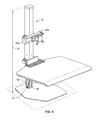
- FIG. 1 is a perspective view of an embodiment of a sit-stand workstation according to the present invention, with a lift assembly thereof in a fully-lowered position;
- FIG. 2 is a partial exploded view of the lift assembly of the embodiment of FIG. 1 ;
- FIG. 3 is a partial sectional view taken along line 3 - 3 of FIG. 1 ;
- FIGS. 4 and 5 are perspective views of the sit-stand workstation according to FIG. 1 , with the lift assembly in a raised position;
- FIG. 6 is a partial view of the bottom surface of the worksurface of the embodiment of FIG. 1 ;
- FIGS. 7A and 7B are partial exploded views of the slide release assembly of the embodiment of FIG. 1 ;
- FIG. 8 is a partial exploded view of the connections between the worksurface and the lift assembly of the embodiment of FIG. 1 ;
- FIG. 9 is a perspective view of an alternate embodiment of a sit-stand workstation according to the present invention.
- directional terms may be used in the specification and claims to describe portions of the present invention (e.g., upper, lower, left, right, etc.). These directional definitions are merely intended to assist in describing and claiming the invention and are not intended to limit the invention in any way.
- reference numerals that are introduced in the specification in association with a drawing figure may be repeated in one or more subsequent figures without additional description in the specification, in order to provide context for other features.
- Sit-stand desks are increasingly common in the workplace to help users combat the recognized negative health effects of sitting all day.
- Many existing sit-stand devices allow only for adjustment of the entire desk surface, which is typically heavy and therefore requires more than one and/or heavy-duty lifting mechanism(s) to be provided. This drives up the costs of these devices and makes them slower and less energy-efficient to operate.
- FIGS. 1-8 generally show a first embodiment of a sit-stand workstation 10 according to the present invention
- FIG. 9 shows a second embodiment of a sit-stand workstation 110
- the workstation 10 of the first embodiment is configured to support a single display 4
- the workstation 110 of the second embodiment is configured to support three displays 4 a - 4 c , as will be described in further detail below. It should be understood that any number of displays could be attached to the workstation in a multitude of various configurations, while remaining within the scope of the present invention.
- the workstation 10 comprises a base plate 12 for supporting the workstation 10 atop an existing support surface 2 , which may be, for example, a desktop or tabletop surface.
- the support surface 2 (see FIG. 1 ) is assumed to be planar and lies in a plane “A.”
- the base plate 12 has a planar bottom surface 13 that lies in a plane “B” and a top surface 15 that lies in a plane “C.”
- four pads 14 a - 14 d are attached to the bottom surface 13 , protect the support surface 2 from damage, and allow the user to quickly and easily slide the workstation 10 around on top of the support surface 2 .
- the base plate 12 permits the workstation 10 to be freestanding, the workstation 10 could alternatively be fixedly attached to the support surface 2 via a clamp mount or through mount.
- fasteners 16 a - 16 d connect through the bottom surface 13 of the base plate 12 and are used to attach a lift assembly 18 to the base plate 12 .
- the lift assembly 18 has a height 19 measured between the bottom end of the inner column 32 and the top end of the outer column 20 .
- the lift assembly 18 comprises an inner column 32 that directly connects to the base plate 12 via the fasteners 16 a - 16 d , an outer column 20 , and an extension and retraction device 42 that is attached between the inner column 32 and outer column 20 .
- the extension and retraction device 42 is a gas cylinder having a cylinder body 43 and a cylinder stroke 45 that extends from and retracts into the cylinder body 43 .
- extension and retraction device 42 in place of the gas cylinder, for example a linear actuator, a cable and pulley system, or one or more springs.
- the extension and retraction device 42 is completely contained within and concealed by the inner column 32 .
- the outer column 20 comprises a plurality of inner planar surfaces 21 a - 21 d (see FIG. 3 , wherein only inner planar surface 21 a is labeled for clarity) and a length 22 measured between the top and bottom ends thereof.
- a top block 26 is fixedly attached to the top end of the outer column 20 by routing each of fasteners 25 a - 25 d through a respective hole 29 a - 29 d located in the top end of the outer column 20 and into a respective hole 28 a - 28 d located in the top block 26 (for clarity, only fasteners 25 a , 25 b and holes 28 a , 28 b are labeled in FIG. 2 ).
- the top block 26 further comprises a bolt hole 27 located therethrough.
- a cylinder adapter 44 having an internally-threaded opening is attached to the cylinder body 43 and a cylinder mounting bolt 49 is passed through the bolt hole 27 in the top block 26 and attached to the internally-threaded threaded opening of the cylinder adapter 44 , thereby rigidly attaching the top end of the gas cylinder 42 to the top end of the outer column 20 .
- a cap 30 is optionally placed over the top end of the lift assembly 18 for aesthetic purposes.
- the outer column 20 includes at its bottom end a plurality of bottom slide mounting holes 24 a - 24 h (for clarity, only hole 24 a labeled in FIG. 2 ) through each of which a respective one of a plurality of bottom slide fasteners 40 a - 40 h is routed (for clarity only fasteners 40 a - 40 d are shown and labeled in FIG. 2 ).
- a pair of the bottom slide fasteners 40 a - 40 h are used to secure each of the bottom slides 39 a - 39 d to the respective inner planar surface 21 a - 21 d of the outer column 20 .
- Each of the bottom slides 39 a - 39 d has a planar outer surface (for clarity only planar outer surface 41 of bottom slide 39 a is labeled in FIG. 2 ) that sits flush with the respective inner planar surface 21 a - 21 d .
- Each of the bottom slides 39 a - 39 d has an inner profile that complements the outer grooved profile of the inner column 32 (see FIG. 3 ), such that the bottom slides 39 a - 39 d smoothly and stably engage the inner column 32 as the lift assembly 18 is raised and lowered via movement of the outer column 20 .
- the inner column 32 has a length 33 measured between the top and bottom ends thereof.
- the outer column 20 is axially aligned with and fully surrounds the inner column 32 , almost entirely conceals the inner column 32 from view when the lift assembly 18 is in its fully-lowered position, and is raised directly above the inner column 32 when the lift assembly 18 is in a raised position.
- at least 90 percent of the length 33 of the inner column 32 is concealed within and completely surrounded by the outer column 20 when the lift assembly 18 is in its fully-lowered position.
- at least a portion of the length 33 of the inner column 32 is concealed within and completely surrounded by the outer column 20 .
- Each of a plurality of top slides 34 a - 34 d are attached to the top end of the inner column 32 via a respective one of a plurality of top slide fasteners 35 a - 35 d (for clarity only slides 34 a , 34 b and fasteners 35 a , 35 b are labeled in FIG. 2 ).
- Each of the top slides 34 a - 34 d has a planar outer surface (for clarity only planar outer surface 36 of top slide 34 b is labeled in FIG. 2 ) that sits flush with the respective inner planar surface 21 a - 21 d of the outer column 20 .
- each of the top slides 34 a - 34 d has an inner profile that complements the outer grooved profile of the inner column 32 .
- the top slides 34 a - 34 d permit the outer column 20 to move smoothly and stably along the length 33 of the inner column 32 as the height 19 of the lift assembly is raised or lowered.
- the inner profile and planar outer surfaces of the top slides 34 a - 34 d (which are fixedly attached to the inner column 32 ) and the inner profile and planar outer surfaces of the bottom slides 39 a - 39 d (which are fixedly attached to the outer column 20 ) comprise all of the contact surfaces between the inner column 32 and outer column 20 , and all surfaces of the top slides 34 a - 34 d and the bottom slides 39 a - 39 d are completely concealed within the lift assembly 18 as its height 19 is adjusted. Said another way, in this embodiment all of the contact or sliding surfaces between the inner column 32 and outer column 20 are completely concealed as the height 19 of the lift assembly 18 is adjusted.
- a cylinder locking mechanism 46 Attached to the bottom end of the gas cylinder 42 is a cylinder locking mechanism 46 that is attached to a cylinder release cable 50 .
- the cylinder locking mechanism 46 arrests movement of the stroke 45 of the gas cylinder 42 , thereby preventing the height 19 of the lift assembly 18 from being adjusted.
- pulling on the cylinder release cable 50 causes the cylinder locking mechanism 46 to engage the cylinder release pin (not shown), thereby freeing the stroke 45 of the gas cylinder 42 and permitting the height 19 of the lift assembly 18 to be adjusted.
- a lower mount pin 48 is routed through a passage in the cylinder locking mechanism 46 and a pair of lower mount holes (only lower mount hole 38 labeled in FIG.
- the cylinder release cable 50 enters the inner column 32 via a cable slot 37 located at the lower end of the inner column 32 .
- a pair of attachment brackets 55 , 61 are clamped around the outer column 20 and support, respectively, support beam row 56 and worksurface 71 at fixed locations along the length 22 of the outer column 20 .
- Support beam row 56 comprises a beam member 57 and has a length 58 that lies in a plane “F” when the beam member 57 is attached to the outer column via attachment bracket 55 .
- a display support assembly 60 is attached to the beam member 57 and supports display 4 . The display support assembly 60 is moveable along the length 58 of the beam member 57 , as desired by the user.
- a pair of beam end caps 59 a , 59 b cover the ends of the beam member 57 .
- the attachment bracket 61 has a pair of cable routers 62 a , 62 b that are each rotatably attached to the attachment bracket 61 via a respective pin 63 a , 63 b .
- the cable routers 62 , 62 b as well as identical cable routers (not labeled) attached to the attachment bracket 55 , can be used to keep device cables organized and safe from damage as the height 19 of the lift assembly 18 is adjusted.
- the worksurface 71 is fixedly secured to a worksurface mounting bracket 65 via a plurality of worksurface fasteners 67 a - 67 e (see FIG. 8 ), and the worksurface mounting bracket 65 is attached to a clamp block 64 which has been fitted between the worksurface mounting bracket 65 and the outer column 20 via a pair of fasteners 66 a , 66 b that are routed through the clamp block 64 and into bracket mounting holes 23 a , 23 b located on the outer column 20 .
- the worksurface mounting bracket 65 is also securely attached to the attachment bracket 61 via a plurality of fasteners (not shown), thereby clamping the worksurface 71 to the outer column 20 .
- an accessory holder 68 having an upright back portion 69 and a bottom portion 70 —which in this embodiment is textured—is clamped over the worksurface mounting bracket 65 and clamp block 64 .
- the accessory holder 68 can hold electronic devices, e.g., a smartphone or tablet, and/or personal items, e.g., a wallet or keys, in a convenient, easy-to-reach location.
- the worksurface 71 has a top surface 79 that lies in a plane “E”, a curved front portion, a pair of finger slots 81 a , 81 b running along respective side surfaces thereof, and a bottom surface 72 that lies in a plane “D.”
- the finger slots 81 a , 81 b provide a comfortable place for the user to place their hands as the lift assembly 18 is being manually raised and lowered. Referring now to FIGS.
- the bottom surface 72 has a slide release cutout 73 , a pair of spring seats 74 a , 74 b , a pair of mounting holes 75 a , 75 b , a cable slot 76 in which the cylinder release cable 50 is routed, a slide link cutout 77 , and a bracket cutout 78 .
- the slide release assembly 82 comprises a slide release 83 , a slide link 90 , and a cable tension adjustment bracket 94 . Both the cable tension adjustment bracket 94 and the slide link 90 are attached to the end 51 of the release cable 50 .
- the slide release 83 is mounted along the finger slot 81 b and has a curved shape to its front side to match the curvature of the finger slot 81 b .
- a pair of locating tabs 84 a , 84 b are provided on the slide release 83 so that the user can quickly locate the slide release 83 with their fingers without the need to look at the side of the worksurface 71 .
- Spring 89 a is seated within spring seat 74 a and spring 89 b is seated within spring seat 74 b , and the top side of the slide release includes notches to accommodate the ends of the springs 89 a , 89 b .
- the slide release 83 is attached to the bottom surface 72 of the worksurface 71 via fasteners 86 a , 86 b that extend respectively through fastener slots 85 a , 85 b in the slide release 83 and attach respectively to mounting holes 75 a , 75 b .
- the springs 89 a , 89 b are compression springs that bias the slide release 83 such that its surface containing the locating tabs 84 a , 84 b sits flush with the finger slot 81 b when the slide release 83 is not being depressed.
- the slide release 83 also includes a post 87 on its top side that engages a post hole 92 located on the slide link 90 .
- the slide link 90 is pivotably attached to the bottom surface 72 of the worksurface 71 via a fastener 91 .
- the slide link 90 also comprises a cable end attachment hole 93 that engages with an attachment hook 53 located at the end 51 of the release cable 50 .
- the fastener slots 85 a , 85 b permit the slide release 83 to be depressed against the springs 89 a , 89 b into the slide release cutout 73 . Doing so causes the post 87 , which is engaged with the post hole 92 on the slide link 90 , to force the slide link 90 to rotate about the axis of the fastener 91 , thereby moving the cable end attachment hole 93 towards the finger slot 81 b .
- the end 51 of the release cable 50 is attached to the cable end attachment hole 93 , so long as the release cable 50 is sufficiently taut the opposite end of the release cable will be pulled, thereby temporarily unlocking the cylinder locking mechanism 46 and permitting the height 19 of the lift assembly 18 to be adjusted so long as the slide release 83 remains depressed.
- the springs 89 a , 89 b push the slide release 83 back into its default position, thereby removing the pulling force from the release cable 50 and causing the cylinder locking mechanism 46 to return to its default, locked position.
- the user can only adjust the height 19 of the lift assembly 18 while the slide release assembly 82 is activated by depressing the slide release 83 .
- the slide release assembly 82 need not be mounted to the bottom surface 72 of the worksurface 71 , but could instead be mounted elsewhere on the worksurface 71 or elsewhere on the sit-stand workstation 10 , or could be provided as a separable module that could be attached to the support surface or another surface within the usage environment.
- the slide release assembly 82 need not be hand controlled, but could instead be controlled by a foot pedal.
- the height 19 of the lift assembly 18 is adjusted manually by the user by gently lifting up or pressing down on the worksurface 71 as the slide release assembly 82 is being actuated. In alternate embodiments, the height 19 of the lift assembly 18 could be adjusted electronically.
- the cable tension adjustment bracket 94 includes a hook 95 that engages with a notched portion 52 located at the end 51 of the release cable and a pair of fastener slots 97 a , 97 b through which a pair of fasteners 96 a , 96 b are routed to releasably attach the bracket 94 to the bottom surface 72 of the worksurface.
- the fasteners 96 a , 96 b are loosened, the position of the bracket 94 is adjusted accordingly by sliding the position of the fastener slots 97 a , 97 b with respect to the fasteners 96 a , 96 b , and the fasteners 96 a , 96 b are retightened.
- Attached along the cable slot 76 is a cable retaining tab 98 that is attached to the bottom surface 72 of the worksurface 71 via a fastener 99 and that acts to maintain the release cable 50 within the cable slot 76 between the cable retaining tab 98 and the slide release assembly 82 .
- more than one cable retaining tab 98 could be provided along the length of the cable slot 76 .
- FIG. 9 shows an alternate embodiment of a sit-stand workstation 110 in which the support beam row 156 supports each of three displays 4 a - 4 c via a respective one of a plurality of display support assemblies 160 a - 160 c .
- the support beam row 156 comprises a center beam member 157 and a pair of side beam members 154 a , 154 b that are each attached to the center beam member 157 via a respective one of a pair of hinges 188 a , 188 b .
- the sit-stand workstation 110 comprises a lift assembly 118 that extends from a base plate 112 and supports a worksurface 171 and the support beam row 156 therefrom.
Abstract
Description
Claims (20)
Priority Applications (1)
| Application Number | Priority Date | Filing Date | Title |
|---|---|---|---|
| US14/561,910 US9366379B2 (en) | 2013-12-05 | 2014-12-05 | Sit-stand workstation with display support apparatus |
Applications Claiming Priority (3)
| Application Number | Priority Date | Filing Date | Title |
|---|---|---|---|
| US201361912418P | 2013-12-05 | 2013-12-05 | |
| US201462009325P | 2014-06-08 | 2014-06-08 | |
| US14/561,910 US9366379B2 (en) | 2013-12-05 | 2014-12-05 | Sit-stand workstation with display support apparatus |
Publications (2)
| Publication Number | Publication Date |
|---|---|
| US20150159804A1 US20150159804A1 (en) | 2015-06-11 |
| US9366379B2 true US9366379B2 (en) | 2016-06-14 |
Family
ID=52144915
Family Applications (2)
| Application Number | Title | Priority Date | Filing Date |
|---|---|---|---|
| US14/561,910 Active US9366379B2 (en) | 2013-12-05 | 2014-12-05 | Sit-stand workstation with display support apparatus |
| US15/037,239 Expired - Fee Related US10180209B2 (en) | 2013-12-05 | 2014-12-05 | Expandable multi-display support apparatus |
Family Applications After (1)
| Application Number | Title | Priority Date | Filing Date |
|---|---|---|---|
| US15/037,239 Expired - Fee Related US10180209B2 (en) | 2013-12-05 | 2014-12-05 | Expandable multi-display support apparatus |
Country Status (3)
| Country | Link |
|---|---|
| US (2) | US9366379B2 (en) |
| CA (1) | CA2873534C (en) |
| WO (1) | WO2015085243A1 (en) |
Cited By (11)
| Publication number | Priority date | Publication date | Assignee | Title |
|---|---|---|---|---|
| USD805523S1 (en) * | 2014-06-06 | 2017-12-19 | Innovative Office Products, Llc | Support apparatus |
| US20180209579A1 (en) * | 2016-01-20 | 2018-07-26 | Innovative Office Products, Llc | Electric sit-stand workstation with display support apparatus |
| US20190021486A1 (en) * | 2016-10-25 | 2019-01-24 | Shaoxing Contuo Transmission Technology Co., Ltd. | Lifting table |
| US10405647B2 (en) * | 2017-08-21 | 2019-09-10 | Versa Products, Inc | Compact, motorized, height-adjustible, software-controlled desktop system |
| US20200375361A1 (en) * | 2019-05-28 | 2020-12-03 | Brunswick Corporation | Vertically adjustable pedestal for boat accessory |
| US11039684B2 (en) | 2018-06-06 | 2021-06-22 | Innovative Office Products, Llc | Arm-based sit-stand workstation |
| USD958122S1 (en) * | 2018-09-14 | 2022-07-19 | Shenzhen Vgoode Technologies Co., Ltd. | Display cart |
| USD960147S1 (en) | 2019-01-25 | 2022-08-09 | Kiosk Group, Inc. | Kiosk display apparatus |
| US11614199B2 (en) | 2019-05-28 | 2023-03-28 | Brunswick Corporation | Vertically adjustable pedestal for boat accessory |
| US20230189456A1 (en) * | 2021-12-13 | 2023-06-15 | Qisda Corporation | Display device and fixing module thereof |
| US11779107B1 (en) | 2022-12-13 | 2023-10-10 | Victor Hugo Hernandez | Movable desk with adjustable lift and tilt |
Families Citing this family (55)
| Publication number | Priority date | Publication date | Assignee | Title |
|---|---|---|---|---|
| US9746124B2 (en) * | 2012-06-04 | 2017-08-29 | Ole Falk Smed | Adjustable multi-monitor support assembly |
| EP2937617B1 (en) * | 2014-04-24 | 2017-03-01 | Ondal Medical Systems GmbH | Rotatable connection with limitation of the rotational angle |
| EP2937618B1 (en) | 2014-04-24 | 2017-09-06 | Ondal Medical Systems GmbH | Rotatable connection with limitation of the rotational angle |
| EP2937619B1 (en) | 2014-04-24 | 2017-03-15 | Ondal Medical Systems GmbH | Rotatable connection with limitation of the rotational angle |
| CN105003797B (en) | 2014-04-24 | 2019-05-31 | 欧达尔医疗系统有限责任公司 | What rotation angle was limited is rotatably connected device |
| USD787237S1 (en) * | 2016-01-20 | 2017-05-23 | Innovative Office Products, Llc | Sit-stand workstation |
| USD827337S1 (en) * | 2016-03-07 | 2018-09-04 | Spindle 360, Inc. | Computer desk |
| US20170296298A1 (en) * | 2016-04-14 | 2017-10-19 | Michael J. Sillers | Apparatus and methods for preventing or reducing repetitive use injuries in the operating room |
| TWI612815B (en) * | 2016-05-17 | 2018-01-21 | 緯創資通股份有限公司 | Display device and wall mount module thereof |
| USD829023S1 (en) * | 2016-12-26 | 2018-09-25 | Changzhou Bxinyuse Lift Table Manufacturing Co, Ltd | Adjustable sit and stand desk |
| US10844996B2 (en) * | 2016-12-28 | 2020-11-24 | Panasonic Intellectual Property Management Co., Ltd. | Display device and stand set |
| USD849456S1 (en) * | 2017-04-11 | 2019-05-28 | Humanscale Corporation | Workstation |
| USD831623S1 (en) * | 2017-04-27 | 2018-10-23 | Innovative Office Products, Llc | Display support |
| US10463147B2 (en) * | 2017-06-09 | 2019-11-05 | Innovative Office Products, Llc | Sit-stand workstation with adjustable keyboard tray |
| US20180352954A1 (en) * | 2017-06-13 | 2018-12-13 | John Keenan | Wall Storage System |
| CN107906326B (en) * | 2017-07-13 | 2019-05-17 | 国网浙江省电力公司湖州供电公司 | A kind of substation's display multi-screen support frame |
| CN107559548A (en) * | 2017-09-27 | 2018-01-09 | 泰州市创新电子有限公司 | A kind of lifting support |
| US10485335B1 (en) * | 2017-11-14 | 2019-11-26 | Ergotect Corporation | Workstation lift and tilt assembly |
| US10993527B2 (en) * | 2017-11-27 | 2021-05-04 | Thermogenesis Group, Inc. | Powered sit-stand desk |
| USD854637S1 (en) * | 2018-05-07 | 2019-07-23 | Coulter Ventures, LLC | Exercise stand |
| EP3790634B1 (en) | 2018-05-07 | 2022-12-14 | Coulter Ventures LLC | Weightlifting machine |
| TWM585469U (en) * | 2018-05-18 | 2019-10-21 | 黃銘賢 | Display stand |
| TWM586510U (en) * | 2018-05-18 | 2019-11-11 | 黃銘賢 | Multi-display stand |
| KR102094956B1 (en) * | 2018-05-21 | 2020-03-30 | 주식회사 브이터치 | Display device for autonomous vehicle |
| USD933669S1 (en) * | 2018-06-05 | 2021-10-19 | Innovative Office Products, Llc | Display support |
| TWI670585B (en) * | 2018-10-26 | 2019-09-01 | 恰得美企業有限公司 | Lifting screen |
| USD909395S1 (en) * | 2018-10-30 | 2021-02-02 | CKnapp Sales, Inc. | Display mount |
| USD901514S1 (en) * | 2018-10-30 | 2020-11-10 | CKnapp Sales, Inc. | Display mount |
| USD895635S1 (en) * | 2018-11-06 | 2020-09-08 | Dell Products L.P. | Dual monitor stand |
| USD888812S1 (en) * | 2018-12-29 | 2020-06-30 | Bonsai Technology Company | Camera holder |
| GB2580417A (en) * | 2019-01-11 | 2020-07-22 | Arrow Group Global Ltd | Display device support arm |
| US10816131B2 (en) | 2019-01-29 | 2020-10-27 | Mong-yu Lee | Liftable screen stand |
| CN111521209A (en) * | 2019-02-01 | 2020-08-11 | 深圳市道通科技股份有限公司 | Calibration system and calibration support thereof |
| US11543074B1 (en) * | 2019-06-12 | 2023-01-03 | Michael John Sears | Track-mounted workstation assembly |
| USD920451S1 (en) * | 2019-08-30 | 2021-05-25 | Rep Fitness, LLC | Accessory for weightlifting equipment |
| US11065755B2 (en) * | 2019-10-08 | 2021-07-20 | Louis Chuang | Foot-operated bicycle work stand |
| CN112682623A (en) * | 2019-10-18 | 2021-04-20 | 江苏固泰建筑材料科技有限公司 | Synthesize a steel corbel for gallows |
| USD951940S1 (en) * | 2019-11-19 | 2022-05-17 | CKnapp Sales, Inc. | Display mount |
| CN111946983A (en) * | 2020-06-19 | 2020-11-17 | 窦崧 | Monitoring display support frame for monitoring equipment |
| CN111963861A (en) * | 2020-07-31 | 2020-11-20 | 南京巨鲨显示科技有限公司 | Piece table display motion system is read to medical science intelligence |
| USD947858S1 (en) * | 2020-08-27 | 2022-04-05 | Xi'an Yueting Chunfeng Technology Co., Ltd. | Display mount |
| USD937845S1 (en) * | 2020-08-27 | 2021-12-07 | Xi'an Yueting Chunfeng Technology Co., Ltd. | Display mount |
| CN112128534A (en) * | 2020-09-11 | 2020-12-25 | 衡阳斯巴克信息科技有限公司 | Mobile computer application program development simulation device |
| USD936053S1 (en) * | 2020-09-17 | 2021-11-16 | Shenzhen Prime Technology Co., Ltd | Display mount |
| CN112178383A (en) * | 2020-09-27 | 2021-01-05 | 诸暨企为科技有限公司 | Display device for digital security field |
| US11768521B2 (en) | 2020-10-02 | 2023-09-26 | Kareim Emam | Auxiliary monitor bracket for laptops |
| CN112268210A (en) * | 2020-10-26 | 2021-01-26 | 河南省儿童医院郑州儿童医院 | ICU medical record equipment |
| CN112923204B (en) * | 2021-01-25 | 2022-06-14 | 无锡新智康医疗科技有限公司 | Information storage device for service system background and use method thereof |
| CN113007511A (en) * | 2021-02-01 | 2021-06-22 | 深圳市多为通讯科技有限公司 | LED display screen connecting device of angularly adjustable |
| PL4053358T3 (en) * | 2021-03-04 | 2024-03-04 | Worxsafe Ab | A telescopic edge protection post |
| WO2022246964A1 (en) * | 2021-05-24 | 2022-12-01 | 南京瑞贻电子科技有限公司 | Oscillograph support device having signal shielding function, and support method therefor |
| CN113339670A (en) * | 2021-05-25 | 2021-09-03 | 赵文聪 | DLP screen frame and DLP screen |
| KR102590342B1 (en) * | 2021-10-20 | 2023-10-16 | 엘지전자 주식회사 | Display stand |
| US11754217B2 (en) * | 2021-11-23 | 2023-09-12 | CKnapp Sales, Inc. | Telescoping monitor mount |
| USD1017741S1 (en) | 2022-01-07 | 2024-03-12 | Rep Fitness Llc | Shroud for weight stack |
Citations (15)
| Publication number | Priority date | Publication date | Assignee | Title |
|---|---|---|---|---|
| US6189843B1 (en) * | 1999-06-04 | 2001-02-20 | Joel W. Pfister | Linear motion table leg |
| US20040118984A1 (en) * | 2002-09-27 | 2004-06-24 | Samsung Electronics Co., Ltd. | Display apparatus |
| US6997422B2 (en) * | 2002-08-21 | 2006-02-14 | Ergotron, Inc. | Stand |
| US20070138356A1 (en) * | 2003-12-30 | 2007-06-21 | Mats Johansson | Display stand |
| US20070205340A1 (en) | 2006-03-06 | 2007-09-06 | Samsung Electronics Co., Ltd. | Supporting device for display units |
| US20070252919A1 (en) | 2006-04-27 | 2007-11-01 | Mcgreevy Roy L | Remotely controlled adjustable flat panel display support system |
| US7364124B2 (en) | 2002-10-17 | 2008-04-29 | Furukawa Co., Ltd. | Elevator device for television camera |
| US7752932B2 (en) | 2008-04-06 | 2010-07-13 | Hiwin Mikrosystem Corp. | Linear actuator |
| US7789355B2 (en) * | 2008-01-22 | 2010-09-07 | Hong Fu Jin Precision Industry (Shenzhen) Co., Ltd. | Support stand for flat display monitor and elevator used for support stand |
| US20110278414A1 (en) | 2009-11-13 | 2011-11-17 | Ergotron, Inc. | Vertical spring lift systems |
| US8333159B2 (en) | 2010-10-06 | 2012-12-18 | Schroer Manufacturing Company | Veterinary table assembly with rotatable table |
| US8342465B2 (en) | 2007-05-31 | 2013-01-01 | Michael Koder | Height adjustable column, in particular for tables |
| US20130126682A1 (en) | 2011-09-09 | 2013-05-23 | Alan L. Tholkes | Computer lift |
| US8601889B2 (en) * | 2008-07-18 | 2013-12-10 | weiss Präzisionstechnik GmbH & Co. KG | Telescoping dual-spindle drive |
| US20140332653A1 (en) | 2010-05-27 | 2014-11-13 | Ergotron,Inc. | Display positioning apparatus and method |
Family Cites Families (60)
| Publication number | Priority date | Publication date | Assignee | Title |
|---|---|---|---|---|
| US676443A (en) | 1900-03-17 | 1901-06-18 | Samuel C Parish | Book-support. |
| US3006592A (en) | 1959-12-29 | 1961-10-31 | Jr Thomas J Davis | Form brace |
| JPS57144399A (en) | 1981-02-27 | 1982-09-06 | Mitsutoyo Seisakusho | Joint type stand for utility equipment |
| US4645167A (en) | 1985-02-19 | 1987-02-24 | Hardwick Gary L | Accessory mounting arrangement for boat seats |
| DE3805424C1 (en) * | 1988-02-22 | 1988-12-01 | Rittal-Werk Rudolf Loh Gmbh & Co Kg, 6348 Herborn, De | |
| US4950100A (en) * | 1989-05-05 | 1990-08-21 | Tru-Bore Engineering | Movable support arm |
| US5454042A (en) | 1991-04-12 | 1995-09-26 | Drever; Leslie | Audio-video source boom support assembly having improved articulation capability |
| US5154390A (en) | 1991-08-30 | 1992-10-13 | Bain Charles E | Articulated stand for supporting object |
| US5518083A (en) * | 1995-03-20 | 1996-05-21 | Blennert; George | Swing arm tree stand |
| US5813646A (en) | 1995-10-10 | 1998-09-29 | Bartholomae; Edward E. | Device for mounting a receptacle |
| DE29707145U1 (en) * | 1997-04-21 | 1997-06-26 | Li Chi Hsien | Concept holder |
| US6343006B1 (en) | 1998-11-20 | 2002-01-29 | Jerry Moscovitch | Computer display screen system and adjustable screen mount, and swinging screens therefor |
| US6466432B1 (en) | 1999-07-12 | 2002-10-15 | Frank Beger | Instrument and service unit for a surgical operating area |
| WO2001035196A1 (en) | 1999-11-12 | 2001-05-17 | Mass Engineered Design | Modular lcd display system |
| WO2003009269A2 (en) | 2001-07-18 | 2003-01-30 | Daniel Dunn | Multiple flat panel display system |
| GB0120055D0 (en) | 2001-08-17 | 2001-10-10 | Ronford Baker Engineering Comp | A support for a camera |
| DE60204162T2 (en) | 2001-11-05 | 2006-01-26 | Steris Inc., Temecula | MEDICAL HANGER WITH TWO AXES |
| US7463494B2 (en) | 2002-01-21 | 2008-12-09 | Pep West, Inc. | System for insertion and extraction of a printed circuit board module into and out of a subrack |
| DE10205869B4 (en) | 2002-02-13 | 2010-04-15 | Mavig Gmbh | Carrier for carrying at least one display device |
| CA2518160A1 (en) | 2003-03-18 | 2004-09-30 | Hill-Rom Services, Inc. | Radial arm system for patient care equipment |
| US7261265B2 (en) | 2003-06-20 | 2007-08-28 | Vantage Point Products Corp. | System for mounting a flat panel display |
| TWM254544U (en) * | 2003-10-29 | 2005-01-01 | Chin-Chih Lin | Pivot shaft structure for flat displaying device |
| US7055973B2 (en) | 2003-12-15 | 2006-06-06 | Rosco Inc. | Mirror mounting assembly |
| US7823583B2 (en) | 2004-03-30 | 2010-11-02 | Energy Innovations, Inc. | Solar collector mounting array |
| KR100586983B1 (en) | 2004-05-21 | 2006-06-08 | 삼성전자주식회사 | Monitor apparatus |
| EP1942299B1 (en) | 2004-06-10 | 2010-09-22 | Humanscale Corporation | Mechanism for positional adjustment of an attached device |
| CA2521790A1 (en) | 2004-09-30 | 2006-03-30 | Compx International Inc. | Support for flat monitors |
| US7467772B2 (en) | 2004-10-12 | 2008-12-23 | Target Brands, Inc. | Pivoting display stand |
| US8091716B2 (en) | 2005-01-26 | 2012-01-10 | Helen Bair | Image display system |
| US7325777B2 (en) * | 2005-02-18 | 2008-02-05 | Gordon Daniel Thiessen | Portable articulating tool support |
| US20070237572A1 (en) * | 2005-02-18 | 2007-10-11 | British Columbia Institute Of Technology | Portable articulationg tool support |
| TWM278930U (en) * | 2005-04-29 | 2005-10-21 | Innolux Display Corp | A supporting bracket and liquid crystal display device using the same |
| US7264212B2 (en) * | 2005-05-20 | 2007-09-04 | Chin-Jui Hung | Monitor-holding device |
| GB0516913D0 (en) * | 2005-08-18 | 2005-09-28 | Avf Group Ltd | Tilting mechanism |
| KR100779252B1 (en) * | 2006-01-23 | 2007-11-27 | 코스텔(주) | Built-in display device |
| US20070102607A1 (en) * | 2005-11-07 | 2007-05-10 | Tuang-Hock Koh | Monitor support device |
| US7510154B2 (en) | 2005-11-17 | 2009-03-31 | Innovative Office Products, Inc. | Cabinet mount arm |
| US7434776B2 (en) | 2006-01-10 | 2008-10-14 | Shawn T. Dennison | Mounting method and system |
| US8230863B2 (en) | 2006-05-30 | 2012-07-31 | Mini-Lap Technologies, Inc. | Platform for fixing surgical instruments during surgery |
| US20070278371A1 (en) * | 2006-05-31 | 2007-12-06 | Ching-Yang Wang | Holder |
| US7448584B2 (en) * | 2006-07-10 | 2008-11-11 | Hoolin Research Company Limited | Wall mounting monitor bracket |
| US20080011924A1 (en) * | 2006-07-17 | 2008-01-17 | Chin-Chu Li | Rotating shaft structure for a supporting frame |
| US7748666B2 (en) | 2006-09-15 | 2010-07-06 | Innovative Office Products, Inc. | Extension arm with moving clevis |
| WO2008042346A2 (en) | 2006-09-28 | 2008-04-10 | Stryker Corporation | Medical equipment transfer arrangement |
| US8000090B2 (en) | 2006-11-16 | 2011-08-16 | Jerry Moscovitch | Multi-monitor support structure |
| US20090173847A1 (en) | 2007-01-24 | 2009-07-09 | Wolfgang Dittmer | Accessory Holder |
| US7922132B2 (en) | 2007-01-24 | 2011-04-12 | Humanscale Corporation | Accessory holder |
| DE102007006892A1 (en) | 2007-02-13 | 2008-08-14 | University Of Dundee | Holding device for medical purposes, has joint with two joint parts, which has meshed bosh element in warp connection with one another and mutual bosh elements are aligned perpendicular to support arm |
| US20100001153A1 (en) * | 2008-07-03 | 2010-01-07 | Omnimount Systems, Inc. | Cam lock for cantilever mounting device |
| US8050022B2 (en) | 2008-10-28 | 2011-11-01 | William C. McIntyre, P.E., LLC | System and method for covering a monitor screen |
| TW201030266A (en) | 2009-01-05 | 2010-08-16 | Peerless Ind Inc | Multiple arm articulating mounting system |
| US8359709B2 (en) | 2009-02-18 | 2013-01-29 | Van Gennep Jan | Locking hinge assembly |
| US20100128423A1 (en) | 2009-03-10 | 2010-05-27 | Jerry Moscovitch | Stand for a Plurality of Electronic Devices |
| DE102009047971B4 (en) | 2009-10-01 | 2011-12-01 | Dräger Medical GmbH | Suspension device and method for its assembly |
| US20110108688A1 (en) * | 2009-11-09 | 2011-05-12 | Gazak Ventures Inc. | Set-top box support kit for LCD wall mounts |
| WO2011155934A1 (en) * | 2010-06-09 | 2011-12-15 | Innovative Office Products, Inc. | Articulating monitor arm with cable and spring |
| TWM396551U (en) | 2010-09-03 | 2011-01-11 | ming-xian Huang | Screen holder capable of adjusting screen angle |
| GB2496589B (en) | 2011-11-10 | 2019-05-22 | Bytec Group Ltd | Articulated mechanical arm |
| CN202520126U (en) | 2012-04-10 | 2012-11-07 | 厦门宇龙机械有限公司 | Door hinge for excavator cab |
| WO2013165562A1 (en) | 2012-05-02 | 2013-11-07 | Milestone Av Technologies Llc | Telescoping rail mounting assembly and multiple display mount system |
-
2014
- 2014-12-05 US US14/561,910 patent/US9366379B2/en active Active
- 2014-12-05 WO PCT/US2014/068914 patent/WO2015085243A1/en active Application Filing
- 2014-12-05 CA CA2873534A patent/CA2873534C/en not_active Expired - Fee Related
- 2014-12-05 US US15/037,239 patent/US10180209B2/en not_active Expired - Fee Related
Patent Citations (15)
| Publication number | Priority date | Publication date | Assignee | Title |
|---|---|---|---|---|
| US6189843B1 (en) * | 1999-06-04 | 2001-02-20 | Joel W. Pfister | Linear motion table leg |
| US6997422B2 (en) * | 2002-08-21 | 2006-02-14 | Ergotron, Inc. | Stand |
| US20040118984A1 (en) * | 2002-09-27 | 2004-06-24 | Samsung Electronics Co., Ltd. | Display apparatus |
| US7364124B2 (en) | 2002-10-17 | 2008-04-29 | Furukawa Co., Ltd. | Elevator device for television camera |
| US20070138356A1 (en) * | 2003-12-30 | 2007-06-21 | Mats Johansson | Display stand |
| US20070205340A1 (en) | 2006-03-06 | 2007-09-06 | Samsung Electronics Co., Ltd. | Supporting device for display units |
| US20070252919A1 (en) | 2006-04-27 | 2007-11-01 | Mcgreevy Roy L | Remotely controlled adjustable flat panel display support system |
| US8342465B2 (en) | 2007-05-31 | 2013-01-01 | Michael Koder | Height adjustable column, in particular for tables |
| US7789355B2 (en) * | 2008-01-22 | 2010-09-07 | Hong Fu Jin Precision Industry (Shenzhen) Co., Ltd. | Support stand for flat display monitor and elevator used for support stand |
| US7752932B2 (en) | 2008-04-06 | 2010-07-13 | Hiwin Mikrosystem Corp. | Linear actuator |
| US8601889B2 (en) * | 2008-07-18 | 2013-12-10 | weiss Präzisionstechnik GmbH & Co. KG | Telescoping dual-spindle drive |
| US20110278414A1 (en) | 2009-11-13 | 2011-11-17 | Ergotron, Inc. | Vertical spring lift systems |
| US20140332653A1 (en) | 2010-05-27 | 2014-11-13 | Ergotron,Inc. | Display positioning apparatus and method |
| US8333159B2 (en) | 2010-10-06 | 2012-12-18 | Schroer Manufacturing Company | Veterinary table assembly with rotatable table |
| US20130126682A1 (en) | 2011-09-09 | 2013-05-23 | Alan L. Tholkes | Computer lift |
Non-Patent Citations (4)
| Title |
|---|
| Ergodesktop website, published at least as early as Jun. 30, 2013, retrieved from Internet Archive Wayback Machine, URL: http://web.archive.org/web/20130620103818/http://www.ergodesktop.com/products. |
| Ergotron website, published at least as early as Feb. 1, 2013, retrieved from Internet Archive Wayback Machine, URL: https://web.archive.org/web/20130201215650/http://www.ergotron.com/Portals/0/tp/R1/WF/888-33-307-W.pdf. |
| Ergotron website, published at least as early as Jul. 17, 2013, retrieved from Internet Archive Wayback Machine, URL: https://web.archive.org/web/20130717184943/http://www.ergotron.com/Portals/0/literature/productSheets/english/05-065.pdf. |
| Ergotron website, published at least as early as Mar. 9, 2013, retrieved from Internet Archive Wayback Machine, URL: https://web.archive.org/web/20130309061346/http://www.ergotron.com/Portals/0/literature/productSheets/english/05-118-EA.pdf. |
Cited By (14)
| Publication number | Priority date | Publication date | Assignee | Title |
|---|---|---|---|---|
| USD805523S1 (en) * | 2014-06-06 | 2017-12-19 | Innovative Office Products, Llc | Support apparatus |
| US20180209579A1 (en) * | 2016-01-20 | 2018-07-26 | Innovative Office Products, Llc | Electric sit-stand workstation with display support apparatus |
| US20190021486A1 (en) * | 2016-10-25 | 2019-01-24 | Shaoxing Contuo Transmission Technology Co., Ltd. | Lifting table |
| US10687615B2 (en) * | 2016-10-25 | 2020-06-23 | Shaoxing Contuo Transmission Technology Co., Ltd. | Lifting table |
| US10405647B2 (en) * | 2017-08-21 | 2019-09-10 | Versa Products, Inc | Compact, motorized, height-adjustible, software-controlled desktop system |
| US11039684B2 (en) | 2018-06-06 | 2021-06-22 | Innovative Office Products, Llc | Arm-based sit-stand workstation |
| USD958122S1 (en) * | 2018-09-14 | 2022-07-19 | Shenzhen Vgoode Technologies Co., Ltd. | Display cart |
| USD960147S1 (en) | 2019-01-25 | 2022-08-09 | Kiosk Group, Inc. | Kiosk display apparatus |
| US11028963B2 (en) * | 2019-05-28 | 2021-06-08 | Brunswick Corporation | Vertically adjustable pedestal for boat accessory |
| US20200375361A1 (en) * | 2019-05-28 | 2020-12-03 | Brunswick Corporation | Vertically adjustable pedestal for boat accessory |
| US11614199B2 (en) | 2019-05-28 | 2023-03-28 | Brunswick Corporation | Vertically adjustable pedestal for boat accessory |
| US20230189456A1 (en) * | 2021-12-13 | 2023-06-15 | Qisda Corporation | Display device and fixing module thereof |
| US11889641B2 (en) * | 2021-12-13 | 2024-01-30 | Qisda Corporation | Display device and fixing module thereof |
| US11779107B1 (en) | 2022-12-13 | 2023-10-10 | Victor Hugo Hernandez | Movable desk with adjustable lift and tilt |
Also Published As
| Publication number | Publication date |
|---|---|
| WO2015085243A1 (en) | 2015-06-11 |
| CA2873534A1 (en) | 2015-06-05 |
| US10180209B2 (en) | 2019-01-15 |
| US20150159804A1 (en) | 2015-06-11 |
| WO2015085243A8 (en) | 2015-11-05 |
| CA2873534C (en) | 2017-02-07 |
| US20160281915A1 (en) | 2016-09-29 |
Similar Documents
| Publication | Publication Date | Title |
|---|---|---|
| US9366379B2 (en) | Sit-stand workstation with display support apparatus | |
| US11033102B2 (en) | Height adjustable desktop work surface | |
| US11672334B2 (en) | Display positioning apparatus and method | |
| US9156555B2 (en) | Desk assembly for positioning board-like electronic device | |
| US7938372B2 (en) | Free standing or vehicle mounted 6-axis positionable tray, positionable shelf, cup-holder, stanchion apparatus and related systems | |
| US7703400B2 (en) | Table with a swivelable table top | |
| US20180008037A1 (en) | Motorized, height adjustable desktop system | |
| US9188275B2 (en) | Edge mount positioning apparatus, system, and method | |
| US20180055214A1 (en) | Height-adjustable desk | |
| US10463147B2 (en) | Sit-stand workstation with adjustable keyboard tray | |
| US8459191B2 (en) | Laptop computer desk | |
| US20170318956A1 (en) | Portable Adjustable Desk System | |
| US11039684B2 (en) | Arm-based sit-stand workstation | |
| CA2988100A1 (en) | Height adjustable device with concealed lift mechanism | |
| US7367618B2 (en) | Wireless mouse and keyboard chair mount apparatus | |
| US9125485B2 (en) | Portable lightweight adjustable computer table | |
| US20180255920A1 (en) | Adjustable Support For Computer Peripherals | |
| CN108692147A (en) | Holder is especially used for the holder of portable computer or laptop | |
| GB2433196A (en) | Monitor support apparatus | |
| US8347791B1 (en) | Computer keyboard and mouse tray assembly | |
| US20050211863A1 (en) | Computer workstation | |
| RU2517240C2 (en) | Support element for object and device comprising support element | |
| US20090102335A1 (en) | Workstation | |
| US20230255346A1 (en) | Display positioning apparatus and method | |
| US11668431B2 (en) | Display mounting system |
Legal Events
| Date | Code | Title | Description |
|---|---|---|---|
| AS | Assignment |
Owner name: INNOVATIVE OFFICE PRODUCTS, LLC, PENNSYLVANIA Free format text: ASSIGNMENT OF ASSIGNORS INTEREST;ASSIGNORS:BOWMAN, STEPHEN J.;CARRASQUILLO, PETER J.;SMITH, MICHAEL P.;AND OTHERS;SIGNING DATES FROM 20141211 TO 20141213;REEL/FRAME:034527/0804 |
|
| AS | Assignment |
Owner name: TCF NATIONAL BANK, ILLINOIS Free format text: SECURITY INTEREST;ASSIGNOR:INNOVATIVE OFFICE PRODUCTS, LLC;REEL/FRAME:036559/0070 Effective date: 20150914 |
|
| STCF | Information on status: patent grant |
Free format text: PATENTED CASE |
|
| AS | Assignment |
Owner name: TCF NATIONAL BANK, AS ADMINISTRATIVE AGENT, ILLINO Free format text: SECURITY INTEREST;ASSIGNORS:INNOVATIVE ERGONOMIC SOLUTIONS, LLC;INNOVATIVE OFFICE PRODUCTS, LLC;ERGOTECH GROUP, LLC;REEL/FRAME:045183/0315 Effective date: 20180125 |
|
| MAFP | Maintenance fee payment |
Free format text: PAYMENT OF MAINTENANCE FEE, 4TH YR, SMALL ENTITY (ORIGINAL EVENT CODE: M2551); ENTITY STATUS OF PATENT OWNER: SMALL ENTITY Year of fee payment: 4 |
|
| AS | Assignment |
Owner name: HUMAN ACTIVE TECHNOLOGY, LLC, PENNSYLVANIA Free format text: CHANGE OF NAME;ASSIGNOR:INNOVATIVE OFFICE PRODUCTS, LLC;REEL/FRAME:061620/0078 Effective date: 20220831 |
|
| FEPP | Fee payment procedure |
Free format text: MAINTENANCE FEE REMINDER MAILED (ORIGINAL EVENT CODE: REM.); ENTITY STATUS OF PATENT OWNER: SMALL ENTITY |