US9375333B1 - Implantable device detachment systems and associated devices and methods - Google Patents
Implantable device detachment systems and associated devices and methods Download PDFInfo
- Publication number
- US9375333B1 US9375333B1 US14/641,175 US201514641175A US9375333B1 US 9375333 B1 US9375333 B1 US 9375333B1 US 201514641175 A US201514641175 A US 201514641175A US 9375333 B1 US9375333 B1 US 9375333B1
- Authority
- US
- United States
- Prior art keywords
- coupling element
- elongated member
- implantable device
- shaft
- opening
- Prior art date
- Legal status (The legal status is an assumption and is not a legal conclusion. Google has not performed a legal analysis and makes no representation as to the accuracy of the status listed.)
- Active
Links
- 238000000034 method Methods 0.000 title abstract description 20
- 230000008878 coupling Effects 0.000 claims abstract description 170
- 238000010168 coupling process Methods 0.000 claims abstract description 170
- 238000005859 coupling reaction Methods 0.000 claims abstract description 170
- 230000000717 retained effect Effects 0.000 claims abstract description 51
- 238000006073 displacement reaction Methods 0.000 claims abstract description 15
- 210000004204 blood vessel Anatomy 0.000 claims description 11
- 206010053648 Vascular occlusion Diseases 0.000 claims description 6
- 208000021331 vascular occlusion disease Diseases 0.000 claims description 6
- 201000008450 Intracranial aneurysm Diseases 0.000 claims description 4
- 206010002329 Aneurysm Diseases 0.000 claims description 3
- 238000005516 engineering process Methods 0.000 abstract description 44
- 230000007246 mechanism Effects 0.000 description 6
- 238000004519 manufacturing process Methods 0.000 description 5
- 210000005166 vasculature Anatomy 0.000 description 5
- 238000005452 bending Methods 0.000 description 4
- 230000008901 benefit Effects 0.000 description 4
- 238000007917 intracranial administration Methods 0.000 description 4
- 239000000463 material Substances 0.000 description 4
- 229910001220 stainless steel Inorganic materials 0.000 description 3
- 239000010935 stainless steel Substances 0.000 description 3
- 239000000853 adhesive Substances 0.000 description 2
- 230000001070 adhesive effect Effects 0.000 description 2
- 230000000712 assembly Effects 0.000 description 2
- 238000000429 assembly Methods 0.000 description 2
- 239000007943 implant Substances 0.000 description 2
- 238000002513 implantation Methods 0.000 description 2
- 238000003780 insertion Methods 0.000 description 2
- 230000037431 insertion Effects 0.000 description 2
- 238000005476 soldering Methods 0.000 description 2
- 238000001356 surgical procedure Methods 0.000 description 2
- 230000002792 vascular Effects 0.000 description 2
- 238000012800 visualization Methods 0.000 description 2
- 238000003466 welding Methods 0.000 description 2
- 244000208734 Pisonia aculeata Species 0.000 description 1
- FAPWRFPIFSIZLT-UHFFFAOYSA-M Sodium chloride Chemical compound [Na+].[Cl-] FAPWRFPIFSIZLT-UHFFFAOYSA-M 0.000 description 1
- 230000001154 acute effect Effects 0.000 description 1
- 239000008280 blood Substances 0.000 description 1
- 210000004369 blood Anatomy 0.000 description 1
- 210000005013 brain tissue Anatomy 0.000 description 1
- 230000007547 defect Effects 0.000 description 1
- 230000007812 deficiency Effects 0.000 description 1
- 230000001934 delay Effects 0.000 description 1
- 201000010099 disease Diseases 0.000 description 1
- 208000037265 diseases, disorders, signs and symptoms Diseases 0.000 description 1
- 239000012530 fluid Substances 0.000 description 1
- 230000002496 gastric effect Effects 0.000 description 1
- 230000009191 jumping Effects 0.000 description 1
- 238000003698 laser cutting Methods 0.000 description 1
- 210000005248 left atrial appendage Anatomy 0.000 description 1
- 239000002184 metal Substances 0.000 description 1
- 238000012986 modification Methods 0.000 description 1
- 230000004048 modification Effects 0.000 description 1
- HLXZNVUGXRDIFK-UHFFFAOYSA-N nickel titanium Chemical compound [Ti].[Ti].[Ti].[Ti].[Ti].[Ti].[Ti].[Ti].[Ti].[Ti].[Ti].[Ni].[Ni].[Ni].[Ni].[Ni].[Ni].[Ni].[Ni].[Ni].[Ni].[Ni].[Ni].[Ni].[Ni] HLXZNVUGXRDIFK-UHFFFAOYSA-N 0.000 description 1
- 229910001000 nickel titanium Inorganic materials 0.000 description 1
- 230000037361 pathway Effects 0.000 description 1
- 229920000642 polymer Polymers 0.000 description 1
- 239000012781 shape memory material Substances 0.000 description 1
- 239000011780 sodium chloride Substances 0.000 description 1
- 238000010561 standard procedure Methods 0.000 description 1
- 230000001225 therapeutic effect Effects 0.000 description 1
Images


Classifications
-
- A—HUMAN NECESSITIES
- A61—MEDICAL OR VETERINARY SCIENCE; HYGIENE
- A61B—DIAGNOSIS; SURGERY; IDENTIFICATION
- A61B17/00—Surgical instruments, devices or methods, e.g. tourniquets
- A61B17/12—Surgical instruments, devices or methods, e.g. tourniquets for ligaturing or otherwise compressing tubular parts of the body, e.g. blood vessels, umbilical cord
- A61B17/12022—Occluding by internal devices, e.g. balloons or releasable wires
- A61B17/12027—Type of occlusion
- A61B17/12031—Type of occlusion complete occlusion
-
- A—HUMAN NECESSITIES
- A61—MEDICAL OR VETERINARY SCIENCE; HYGIENE
- A61F—FILTERS IMPLANTABLE INTO BLOOD VESSELS; PROSTHESES; DEVICES PROVIDING PATENCY TO, OR PREVENTING COLLAPSING OF, TUBULAR STRUCTURES OF THE BODY, e.g. STENTS; ORTHOPAEDIC, NURSING OR CONTRACEPTIVE DEVICES; FOMENTATION; TREATMENT OR PROTECTION OF EYES OR EARS; BANDAGES, DRESSINGS OR ABSORBENT PADS; FIRST-AID KITS
- A61F2/00—Filters implantable into blood vessels; Prostheses, i.e. artificial substitutes or replacements for parts of the body; Appliances for connecting them with the body; Devices providing patency to, or preventing collapsing of, tubular structures of the body, e.g. stents
- A61F2/95—Instruments specially adapted for placement or removal of stents or stent-grafts
-
- A—HUMAN NECESSITIES
- A61—MEDICAL OR VETERINARY SCIENCE; HYGIENE
- A61B—DIAGNOSIS; SURGERY; IDENTIFICATION
- A61B17/00—Surgical instruments, devices or methods, e.g. tourniquets
- A61B17/12—Surgical instruments, devices or methods, e.g. tourniquets for ligaturing or otherwise compressing tubular parts of the body, e.g. blood vessels, umbilical cord
- A61B17/12022—Occluding by internal devices, e.g. balloons or releasable wires
- A61B17/12099—Occluding by internal devices, e.g. balloons or releasable wires characterised by the location of the occluder
- A61B17/12109—Occluding by internal devices, e.g. balloons or releasable wires characterised by the location of the occluder in a blood vessel
- A61B17/12113—Occluding by internal devices, e.g. balloons or releasable wires characterised by the location of the occluder in a blood vessel within an aneurysm
- A61B17/12118—Occluding by internal devices, e.g. balloons or releasable wires characterised by the location of the occluder in a blood vessel within an aneurysm for positioning in conjunction with a stent
-
- A—HUMAN NECESSITIES
- A61—MEDICAL OR VETERINARY SCIENCE; HYGIENE
- A61B—DIAGNOSIS; SURGERY; IDENTIFICATION
- A61B17/00—Surgical instruments, devices or methods, e.g. tourniquets
- A61B17/12—Surgical instruments, devices or methods, e.g. tourniquets for ligaturing or otherwise compressing tubular parts of the body, e.g. blood vessels, umbilical cord
- A61B17/12022—Occluding by internal devices, e.g. balloons or releasable wires
- A61B17/12131—Occluding by internal devices, e.g. balloons or releasable wires characterised by the type of occluding device
- A61B17/12168—Occluding by internal devices, e.g. balloons or releasable wires characterised by the type of occluding device having a mesh structure
-
- A—HUMAN NECESSITIES
- A61—MEDICAL OR VETERINARY SCIENCE; HYGIENE
- A61B—DIAGNOSIS; SURGERY; IDENTIFICATION
- A61B17/00—Surgical instruments, devices or methods, e.g. tourniquets
- A61B17/00234—Surgical instruments, devices or methods, e.g. tourniquets for minimally invasive surgery
- A61B2017/00292—Surgical instruments, devices or methods, e.g. tourniquets for minimally invasive surgery mounted on or guided by flexible, e.g. catheter-like, means
-
- A—HUMAN NECESSITIES
- A61—MEDICAL OR VETERINARY SCIENCE; HYGIENE
- A61B—DIAGNOSIS; SURGERY; IDENTIFICATION
- A61B17/00—Surgical instruments, devices or methods, e.g. tourniquets
- A61B2017/00831—Material properties
- A61B2017/00862—Material properties elastic or resilient
-
- A—HUMAN NECESSITIES
- A61—MEDICAL OR VETERINARY SCIENCE; HYGIENE
- A61B—DIAGNOSIS; SURGERY; IDENTIFICATION
- A61B17/00—Surgical instruments, devices or methods, e.g. tourniquets
- A61B2017/00831—Material properties
- A61B2017/00867—Material properties shape memory effect
-
- A—HUMAN NECESSITIES
- A61—MEDICAL OR VETERINARY SCIENCE; HYGIENE
- A61B—DIAGNOSIS; SURGERY; IDENTIFICATION
- A61B17/00—Surgical instruments, devices or methods, e.g. tourniquets
- A61B17/12—Surgical instruments, devices or methods, e.g. tourniquets for ligaturing or otherwise compressing tubular parts of the body, e.g. blood vessels, umbilical cord
- A61B17/12022—Occluding by internal devices, e.g. balloons or releasable wires
- A61B2017/1205—Introduction devices
- A61B2017/12054—Details concerning the detachment of the occluding device from the introduction device
-
- A—HUMAN NECESSITIES
- A61—MEDICAL OR VETERINARY SCIENCE; HYGIENE
- A61B—DIAGNOSIS; SURGERY; IDENTIFICATION
- A61B90/00—Instruments, implements or accessories specially adapted for surgery or diagnosis and not covered by any of the groups A61B1/00 - A61B50/00, e.g. for luxation treatment or for protecting wound edges
- A61B90/39—Markers, e.g. radio-opaque or breast lesions markers
- A61B2090/3966—Radiopaque markers visible in an X-ray image
-
- A—HUMAN NECESSITIES
- A61—MEDICAL OR VETERINARY SCIENCE; HYGIENE
- A61F—FILTERS IMPLANTABLE INTO BLOOD VESSELS; PROSTHESES; DEVICES PROVIDING PATENCY TO, OR PREVENTING COLLAPSING OF, TUBULAR STRUCTURES OF THE BODY, e.g. STENTS; ORTHOPAEDIC, NURSING OR CONTRACEPTIVE DEVICES; FOMENTATION; TREATMENT OR PROTECTION OF EYES OR EARS; BANDAGES, DRESSINGS OR ABSORBENT PADS; FIRST-AID KITS
- A61F2/00—Filters implantable into blood vessels; Prostheses, i.e. artificial substitutes or replacements for parts of the body; Appliances for connecting them with the body; Devices providing patency to, or preventing collapsing of, tubular structures of the body, e.g. stents
- A61F2/95—Instruments specially adapted for placement or removal of stents or stent-grafts
- A61F2/9522—Means for mounting a stent or stent-graft onto or into a placement instrument
-
- A—HUMAN NECESSITIES
- A61—MEDICAL OR VETERINARY SCIENCE; HYGIENE
- A61F—FILTERS IMPLANTABLE INTO BLOOD VESSELS; PROSTHESES; DEVICES PROVIDING PATENCY TO, OR PREVENTING COLLAPSING OF, TUBULAR STRUCTURES OF THE BODY, e.g. STENTS; ORTHOPAEDIC, NURSING OR CONTRACEPTIVE DEVICES; FOMENTATION; TREATMENT OR PROTECTION OF EYES OR EARS; BANDAGES, DRESSINGS OR ABSORBENT PADS; FIRST-AID KITS
- A61F2/00—Filters implantable into blood vessels; Prostheses, i.e. artificial substitutes or replacements for parts of the body; Appliances for connecting them with the body; Devices providing patency to, or preventing collapsing of, tubular structures of the body, e.g. stents
- A61F2/82—Devices providing patency to, or preventing collapsing of, tubular structures of the body, e.g. stents
- A61F2002/823—Stents, different from stent-grafts, adapted to cover an aneurysm
-
- A—HUMAN NECESSITIES
- A61—MEDICAL OR VETERINARY SCIENCE; HYGIENE
- A61F—FILTERS IMPLANTABLE INTO BLOOD VESSELS; PROSTHESES; DEVICES PROVIDING PATENCY TO, OR PREVENTING COLLAPSING OF, TUBULAR STRUCTURES OF THE BODY, e.g. STENTS; ORTHOPAEDIC, NURSING OR CONTRACEPTIVE DEVICES; FOMENTATION; TREATMENT OR PROTECTION OF EYES OR EARS; BANDAGES, DRESSINGS OR ABSORBENT PADS; FIRST-AID KITS
- A61F2/00—Filters implantable into blood vessels; Prostheses, i.e. artificial substitutes or replacements for parts of the body; Appliances for connecting them with the body; Devices providing patency to, or preventing collapsing of, tubular structures of the body, e.g. stents
- A61F2/95—Instruments specially adapted for placement or removal of stents or stent-grafts
- A61F2002/9505—Instruments specially adapted for placement or removal of stents or stent-grafts having retaining means other than an outer sleeve, e.g. male-female connector between stent and instrument
-
- A61F2002/9522—
Definitions
- the present technology relates generally to devices, systems, and methods for delivering implantable devices to a target site or location within the body of a patient. Many embodiments of the present technology relate to devices, systems, and methods for securing an implantable device to a delivery system and detaching an implantable device from a delivery system.
- catheter delivery systems for positioning and deploying therapeutic devices in the vasculature of the human body has become a standard procedure for treating endovascular diseases.
- Such devices are particularly useful in treating areas where traditional operational procedures are impossible or pose a great risk to the patient, for example in the treatment of aneurysms in intracranial blood vessels. Due to the delicate tissue surrounding intracranial blood vessels, such as brain tissue, it is very difficult and often risky to perform surgical procedures to treat defects of the intracranial blood vessels. Advancements in catheter deployment systems have provided an alternative treatment in such cases. Typically, these procedures involve inserting a delivery catheter containing a vascular occlusion device into the vasculature of a patient and guiding it through the vasculature to a predetermined delivery site.
- the delivery catheter also contains a delivery member attached to the vascular occlusion device which can be used to push the occlusion device out of the distal end of the delivery catheter into the delivery site.
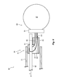
- FIG. 1A is a perspective view of a detachment system in a retained state configured in accordance with an embodiment of the present technology.
- FIG. 1B is a partial cross-sectional side view of the detachment system of FIG. 1A in a retained state configured in accordance with an embodiment of the present technology.
- the expandable component of FIG. 1A is not shown in FIG. 1B for purposes of illustration.
- FIG. 2A is a partial cross-sectional side view of the detachment system shown in FIG. 1A in a released state configured in accordance with an embodiment of the present technology.
- FIGS. 2B-2C are partial cross-sectional side views, and FIG. 2D is a side view, that together show the detachment system of FIGS. 1A-2A during withdrawal of the delivery system configured in accordance with an embodiment of the present technology.
- FIG. 3A is an isolated side view of a handle assembly configured in accordance with the present technology.
- FIG. 3B is a cross-sectional side view of the handle assembly of FIG. 3A shown coupled to an elongated member configured in accordance with the present technology.
- the handle assembly is shown in a retained state.
- FIGS. 3C-3E are cross-sectional side views of the handle assembly of FIGS. 3A and 3B , shown moving from the retained state to a released state and coupled to an elongated member configured in accordance with the present technology.
- FIG. 4A is top view of a detachment system in a retained state configured in accordance with another embodiment of the present technology.
- FIG. 4B is an enlarged side view of a portion of the detachment system of FIG. 4A in a retained state.
- FIGS. 5A and 5B are top views of the detachment system of FIGS. 4A and 4B during withdrawal of the elongated member and shaft configured in accordance with the present technology.
- FIG. 6 is a partial cross-sectional side view of a detachment system in a retained state configured in accordance with another embodiment of the present technology.
- FIG. 7 is partial cross-sectional side view of a detachment system in a retained state configured in accordance with another embodiment of the present technology.
- FIG. 8 is partial cross-sectional side view of a detachment system in a retained state configured in accordance with another embodiment of the present technology.
- the present technology provides devices, systems, and methods for securing an implantable device to a delivery system and controllably detaching the implantable device from the delivery system.
- the devices, systems, and methods of the present technology provide several advantages over conventional detachment systems. For example, the devices, systems, and methods of the present technology firmly secure an implantable device to a delivery system without incorporating a spherically- or ball-shaped coupling element. Because of this, the detachment devices and systems of the present technology are easier to manufacture than conventional detachment systems that incorporate such ball-shaped coupling elements that require tight tolerances due to their small size.
- the elongated member is positioned within a portion of the implantable device, thereby preventing axial displacement of the system in the retained state.
- Several conventional devices include an articulating joint between the delivery system and the implantable device (e.g., including systems incorporating a ball-shape coupling element) that allow the implantable device to move out of axial alignment with the delivery system during delivery and release of the implantable device.
- Other conventional devices have a fixed joint between the delivery system and the implantable device and require the implantable device to move out of axial alignment with the delivery system during delivery and release of the implantable device.
- the detachment systems of the present technology are configured to axially align the implantable device and the delivery system and maintain the axial alignment throughout delivery and release of the implantable device. Additionally, because of this maintained axial alignment, stress caused by the manipulation of the delivery system during insertion into the blood vessel can be absorbed by both the delivery system and the implantable device, thereby reducing fatigue at their mechanical junction.
- distal and proximal within this description, unless otherwise specified, the terms can reference a relative position of the portions of an implantable device and/or an associated catheter device with reference to an operator and/or a location in the vasculature.
- FIGS. 1A and 1B are a top perspective view and a partial cross-sectional side view, respectively, of one embodiment of a detachment system 100 (also referred to as the “system 100 ”) in a retained state configured in accordance with the present technology.
- the system 100 can include a catheter 110 , an implantable device 120 , and an elongated member 130 .
- the catheter 110 can include a catheter 110 , an implantable device 120 , and an elongated member 130 .
- the catheter 110 the implantable device 120
- elongated member 130 For purposes of illustration, only a portion of the catheter 110 , the implantable device 120 , and the elongated member 130 are shown in FIGS. 1A-1B .
- the catheter 110 can include an elongated shaft 114 having a proximal portion (not shown) and a distal portion 111 configured to be intravascularly positioned at a treatment site within a blood vessel (e.g., a small blood vessel) of a human patient.
- the distal portion 111 can include a first coupling element 112 configured to slidably receive a portion of the elongated member 130 therethrough.
- the implantable device 120 can include an expandable component 127 (a portion is shown in FIG. 1A only) configured to at least partially fill an aneurysm (e.g., a cerebral aneurysm) at the treatment site.
- the implantable device 120 can include a second coupling element 122 configured to slidably receive the elongated member 130 .
- the system 100 can be transformable between a retained state in which the elongated member 130 extends through both the first and second coupling elements 112 , 122 to secure the implantable device 120 to the catheter 110 , and a released state in which the elongated member 130 has been withdrawn proximally of the second coupling element 122 to thereby release the implantable device 120 from the shaft 114 .
- the elongated shaft 114 in the embodiment shown in FIGS. 1A and 1B includes a tubular sidewall 117 (e.g., a hypotube) that defines a lumen 119 ( FIG. 1B ) configured to slidably receive the elongated member 130 .
- the lumen 119 can extend distally from the proximal portion (not shown) of the shaft 114 to an opening 121 at the distal portion of the shaft 114 .
- the shaft 114 can be configured to be slidably received by a guide catheter and/or delivery catheter (e.g., a microcatheter), as is known in the art.
- the shaft 114 includes a detent 146 positioned at least partially within the lumen 119 proximal of the first coupling element 112 , and the system 100 further includes a protrusion 148 ( FIG. 1B ) coupled to or associated with an outer surface of the elongated member 130 .
- a tortuous vascular pathway such as within a cranial blood vessel
- the tortuosity and curvature of the vasculature can exert frictional forces against the delivery system. As such, a certain amount of slack is often built into the length of the shaft 114 .
- the delivery catheter and/or shaft 114 can unexpectedly jump forward.
- the protrusion 148 and/or detent 146 operate together to prevent the elongated member 130 from jumping forward too far and pushing the implantable device 120 out of the delivery catheter (not shown) prematurely.
- the shaft 114 may not include a detent 146 and/or a protrusion 148 .
- the first coupling element 112 is integral with or formed by a portion of the sidewall 117 .
- the first coupling element 112 can be a component separate from the sidewall 117 and coupled to the shaft 114 during manufacturing.
- the first coupling element 112 can include a first region 113 and a second region 115 that are configured to slidably receive the elongated member 130 therethrough.
- the first region 113 can include an opening 142 configured to receive a portion of the second coupling element 122 .
- a portion of the sidewall 117 can be removed during manufacturing (e.g., via laser cutting or other suitable techniques) such that a remaining portion of the sidewall 117 along the first region 113 can have a c-shaped or semi-circular cross-section.
- the sidewall 117 along the first region 113 can have other suitable shapes and/or configurations depending on the shape and size and of the opening 142 . It will be appreciated that a length of the first region 113 can be selected to improve the pushability of the system 100 during delivery of the implantable device 120 .
- the second region 115 of the first coupling element 112 can include a cover 118 extending between opposing portions of the sidewall 117 .
- the cover 118 and the sidewall 117 can together enclose a passageway or lumen 116 ( FIG. 1B ) configured to slidably receive the elongated member 130 therethrough.
- the lumen 116 can extend distally from an opening adjacent the first region 113 to an opening positioned at a distal terminus of the shaft 114 and/or the first coupling element 112 .
- the cover 118 can be a separate piece attached to the sidewall 117 during manufacturing, and in other embodiments the cover 118 can be integral with the sidewall 117 .
- the second region 115 can have any desired length based on the length of the cover 118 . As such, in selected embodiments where the system 100 has a relatively short cover 118 , the second region 115 can include a single opening rather than two openings flanking a lumen.
- the implantable device 120 can include the expandable component 127 (shown in a collapsed or low-profile state in FIG. 1A ), a cylindrical hub 124 coupled to a proximal portion of the expandable component 127 , and the second coupling element 122 .
- the expandable component 127 can be a vascular occlusion device.
- the expandable component 127 can be a braid, and one end of the braid can be attached to the hub 124 . Examples of expandable braids suitable for use with the detachment systems of the present technology are described in U.S. patent application Ser. No. 13/230,628, filed Sep. 12, 2011, and U.S. patent application Ser. No. 13/727,029, filed Dec.
- the hub 124 can have any suitable size, shape and/or configuration, and/or all or a portion of the hub 124 can be coated with or made of a radiopaque material to improve visualization of the implantable device 120 during and/or after implantation.
- the second coupling element 122 can be coupled to an inner surface of the hub 124 via adhesive, soldering, welding, and/or other suitable mechanical fixation means).
- the second coupling element 122 can be integral with the hub 124 , coupled to an outer surface of the hub 124 , and/or coupled directly to the expandable component 127 .
- the implantable device 120 may not include a hub 124 and the second coupling element 122 can be coupled directly to the expandable component 127 .
- the implantable device 120 can include a collar 104 coaxially positioned within the hub 124 .
- the collar 104 can have a lumen 128 configured to slidably receive a distal portion 131 ( FIG. 1B ) of the elongated member 130 .
- a proximal portion of expandable component 127 can be positioned around the outer periphery of the collar 104 .
- An inner diameter of the lumen 128 can be greater than that of the elongated member 130 such that a small gap exists between the lumen 128 and the elongated member 130 to reduce the friction between the elongated member 130 and the collar 104 and improve the ease of withdrawal of the elongated member 130 from the lumen 128 and/or implantable device 120 .
- the collar 104 is shown having a cylindrical shape in FIG. 1A , in other embodiments the collar 104 can have any suitable size, shape and/or configuration. Additionally, all or a portion of the collar 104 can be coated with or made of a radiopaque material to improve visualization of the implantable device 120 during and/or after implantation. In particular embodiments, the system 100 may not include a collar 104 .
- the proximal portion of the expandable component 127 can be distributed around and fixed to an interior surface of the hub 124 such that a cavity remains within the hub 124 surrounded by the proximal portion of the expandable component 127 .
- the second coupling element 122 can have an opening 126 ( FIG. 1A ) configured to slidably receive the elongated member 130 therethrough. At least a portion of the second coupling element 122 can be configured to extend proximally beyond the second region 115 of the first coupling element 112 and into the opening 142 .
- the second coupling element 122 is u-shaped.
- the second coupling element 122 includes first and second legs 122 a , 122 b (second leg 122 b not shown in FIG. 1B ) and an intermediate portion 122 c between the legs 122 a - b .
- first and second legs 122 a , 122 b , the intermediate portion 122 c and a proximal portion of the hub 124 and/or expandable component 127 together define a closed path surrounding the opening 126 .
- the legs 122 a , 122 b can be generally linear and can each include a first portion positioned along and fixed to an interior surface of the hub 124 and a second portion extending proximally from the hub 124 .
- all or portions of each of the legs 122 a , 122 b can have other suitable shapes and configurations (e.g., non-linear configurations).
- at least a portion of the intermediate portion 122 c is curved.
- all or portions of the intermediate portion 122 c can have other suitable shapes and configurations (e.g., a square shape, a triangular shape, etc.).
- the second coupling element 122 can be flexible.
- the second coupling element 122 can be configured to bend at least in a direction that is transverse to a longitudinal axis of the first coupling element 112 (as described in greater detail below with respect to FIGS. 2A-2D ).
- the second coupling element 122 can be configured to bend towards the elongated member 130 .
- the second coupling element 122 can be configured to bend in any direction.
- the second coupling element 122 can be made of a thin metal wire (e.g., nitinol or stainless steel) having a diameter that is less than about 0.004 inches.
- the wire can have a diameter that is less than about 0.003 inches (e.g., about 0.002 inches, about 0.001 inches, etc.)
- all or a portion of the second coupling element 122 can be rigid (e.g., stainless steel, a plastic, and/or any material with a suitable thickness to avoid bending or flexing during use) and/or highly flexible (e.g., a thread or filament).
- the second coupling element 122 when the system 100 is in the retained state, a portion of the second coupling element 122 is positioned proximally of the second region 115 of the first coupling element 112 and in the opening 142 of the first coupling element 112 such that the opening 126 in the second coupling element 122 is at least partially aligned with the lumen 116 of the first coupling element 112 .
- the second coupling element 122 can include an inclined portion 123 ( FIG. 1B ) that forms an acute or obtuse angle (e.g., not a 90 degree angle) with respect to a central longitudinal axis of the second coupling element 122 .
- the elongated member 130 can extend distally from the proximal portion of the catheter 110 through the shaft lumen 119 , through the opening 126 in the second coupling element 122 , through the lumen 116 of the first coupling element 112 , and into a proximal portion of the implantable device 120 . While the elongated member 130 is positioned through the opening 126 and at least partially within the lumen 116 , the implantable device 120 is tethered to or otherwise retained with the shaft 114 . In this retained configuration, a central longitudinal axis of the elongated shaft 114 can be generally aligned with a central longitudinal axis of the implantable device 120 so as to reduce the overall profile of the system 100 .
- FIG. 2A is a partial cross-sectional side view of the system 100 in the released state configured in accordance with an embodiment of the present technology.
- the implantable device 120 is decoupled from the shaft 114 .
- the shaft 114 can be withdrawn from the treatment site.
- the detachment systems of the present technology are particularly useful in small vessels or other body lumens with limited space.
- intracranial vessels for example, it can be advantageous to reduce and/or eliminate axial displacement of the shaft 114 and/or the implantable device 120 from their respective central longitudinal axes as the shaft 114 is removed from the patient immediately after removing the elongated member 130 from the opening 126 ( FIG. 1A ) and lumen 116 .
- FIG. 2A shows the detachment system 100 immediately after the elongated member 130 has been removed from the opening 126 ( FIG. 1A ) and lumen 116 .
- a portion of the second coupling element 122 is configured to remain between a portion of the first coupling element 112 and a catheter 110 withdrawal path A even after the elongated member 130 has been withdrawn.
- the inclined portion 123 of the second coupling element 122 can remain positioned proximal to the second region 115 of the first coupling element 112 and at an elevation that positions the inclined portion 123 between the second region 115 and a catheter device withdrawal path A.
- axial displacement refers to an axial displacement of the implantable device 120 and/or the shaft 114 from their respective axial positions in the retained state.
- “Substantial axial displacement” as used herein refers to a displacement that is greater than or equal to an outer diameter (or width, if not a circular shape) of the smaller of the second region 115 and the second coupling element 122 .
- the outer diameter can be that of the first coupling element 112 at a location along the length of the first coupling element 112 longitudinally aligned with a proximal portion of the lumen 116 ( FIG. 2A ).
- the term “without substantial axial displacement” as used herein can include no or close to no axial displacement (e.g., an axial displacement of 0.000 inches, an axial displacement of 0.001 inches.
- the second coupling element 122 can bend or flex out of the withdrawal path A of the second region 115 without substantial axial displacement of the implantable device 120 and without extending beyond the profile of the system 100 .
- the inclined portion 123 flexes or bends as the second region 115 of the first coupling element 112 slides under the second coupling element 122 without substantially axially displacing the implantable device 120 and/or the shaft 114 .
- the system 100 in the released state and as the elongated shaft 114 moves proximally, the system 100 is configured such that the first coupling element 112 slides proximally along the second coupling element 122 within a circumference of the elongated shaft 114 .
- At least a portion of the second coupling element 122 can be made of a shape-memory material that, upon release from the elongated member 130 , assumes a shape or position that is outside of the withdrawal path A. As such, the first coupling element 112 may be pulled proximally past the second coupling element 122 without engaging the second coupling element 122 .
- the first coupling element 112 and/or the second coupling element 122 can have a ramped or inclined surface that can reduce axial displacement of the shaft 114 and/or the implantable device 120 during withdrawal of the shaft 114 .
- the inclined surface of the first and/or second coupling element 112 , 122 can be configured to oppose and/or engage an inclined or non-inclined portion of the other of the first or second coupling element 112 , 122 .
- the first and/or second coupling element 112 , 122 can be rigid and maintain an inclined state in both the retained and released states.
- the first and/or second coupling element 112 , 122 can be flexible material and assume an inclined state in one or both of the retained and released states.
- FIGS. 3A and 3B are isolated side and isolated cross-sectional side views, respectively, of one embodiment of a handle assembly 300 , shown in a retained state, configured for use with the detachment systems of the present technology.
- the handle assembly 300 can have a proximal portion 300 a and a distal portion 300 b .
- the handle assembly 300 can include a housing 302 , a lever 304 coupled to the housing 302 , and a collar 306 positioned at the distal portion 300 b .
- the lever 304 can be coupled to the housing 302 and is moveable between a retained state ( FIGS.
- the lever 304 can be configured to pivot and/or rotate relative to the housing (e.g., about axis 303 ).
- the lever 304 can be a flexible cantilever having a portion fixed to the housing 302 and a free end configured to move towards the housing 302 as the lever 304 is bent or flexed towards the housing 302 (indicated by arrow A).
- the lever 304 can include one or more protrusions configured to be received by one or more cavities in the housing 302 .
- the lever 304 can include a first protrusion 310 and a second protrusion 318 positioned distal to the first protrusion 310 along the length of the lever 304 .
- the lever 304 can include more or fewer than two protrusions (e.g., one protrusion, three protrusions, etc.) and/or can have other suitable shapes and/or configurations.
- the housing 302 can include a channel 308 extending along at least a portion of its length and configured to slidably receive at least a portion of the elongated member 130 (as shown in FIGS. 3C-3E ).
- the housing 302 can further include one or more recesses or cavities adjacent to the channel 308 .
- the housing 302 can include a first recess 314 and a second recess 316 located distally of the first recess 314 along the channel 308 .
- the first and second recesses 314 , 316 can be configured to receive the first and second protrusions 310 , 318 of the lever 304 as the lever 304 moves into the released state.
- the collar 306 can include a lumen 309 extending along at least a portion of its length and configured to slidably receive the elongated member 130 therethrough.
- the lumen 309 can include a first portion 309 a having a first diameter and a second portion 309 b having a second diameter greater than the first diameter and located distal to the first portion 309 a along the length of the lumen 309 .
- the second portion 309 b can be configured to receive an elongated outer member 330 ( FIGS. 3C-3E ) (e.g., an elongated shaft, a delivery sheath, etc.) configured to receive the elongated member 130 slidably therethrough.
- the outer member 330 can have an outer diameter that is greater than the first diameter of the first portion 309 a ; as such, the smaller diameter of the first portion 309 a restricts the outer member 330 from moving proximally of the second portion 309 b .
- at least a portion of the lumen 309 can be tapered in a distal direction.
- the lumen 309 can include a stepped portion 307 between the first portion 309 a and the second portion 309 b .
- the lumen 309 can optionally include a tapered or stepped insert positioned within the lumen 309 (e.g., at the stepped portion 307 ).
- the collar 306 can be removably coupled to the housing 302 via one or more mechanical coupling mechanisms known in the art (e.g., a push tab 305 (shown in FIG. 3A ), a spring-loaded pin, one or more threaded surfaces, etc.). In other embodiments, the collar 306 can be fixed to the housing 302 and/or be integral with the housing 302 .
- FIGS. 3C-3E are cross-sectional side views of the handle assembly 300 shown coupled to a portion of the elongated member 130 and outer member 330 .
- the handle assembly 300 can be moved between the retained state and the released state to decouple the implantable device (not shown) from the detachment system.
- the elongated member 130 can extend distally from a proximal portion of the channel 308 , across first and second recesses 314 , 316 and through at least a portion of the collar lumen 309 and the outer member 330 .
- the elongated member 130 is free to slide axially through the channel 308 and lumen 309 .
- Such freedom of movement can be advantageous, for example, during insertion of the elongated member 130 through the tortuous vascular.
- the handle assembly 300 can be moved to the released state by moving (e.g., pushing, rotating, bending, etc.) the lever 304 towards the channel 308 in the direction of arrow A 1 .
- FIG. 3D shows the handle assembly 300 in an intermediate state. As shown in FIG. 3D , as the lever 304 rotates or pivots towards the channel 308 , the first and second protrusions 310 , 318 also rotate or move towards the channel 308 and engage the elongated member 130 . In the embodiment shown in FIGS.
- the lever 304 is configured such that the first protrusion 310 crosses into the channel 308 before the second protrusion 318 , and thus the first protrusion 310 engages the elongated member 130 before the second protrusion 318 .
- the first protrusion 310 pushes the elongated member 130 into the first recess 314 ( FIG. 3C ) and traps a portion of the elongated member 130 against a backstop 312 in the housing 302 , thereby preventing axial movement of the elongated member 130 in a distal direction when the second protrusion 318 contacts and pushes against the elongated member 130 .
- first and second protrusions 310 and 318 can engage the elongated member 130 at substantially the same time.
- the lever 304 can include a single protrusion (e.g., the second protrusion 318 ).
- the elongated member 130 bends out of alignment. Because a portion of the elongated member 130 proximal of the portion being engaged by the second protrusion 318 is held stationary (relative to the housing 302 ) by the first protrusion 310 , the bending of the elongated member 130 by the second protrusion 318 forces the remaining portion of the elongated member 130 (distal of recess 316 ) to move proximally (as indicated by arrow A 2 ), thereby releasing the implantable device 120 ( FIG. 1A ) from the detachment system.
- the elongated member 130 is fixed to the housing 302 and the lever 304 (in the released state, FIG. 3E ), as the housing 302 and lever 304 are separated from the collar 306 , the elongated member 130 can be pulled proximally through the outer member 330 and removed.
- the handle assembly 300 of the present technology provides several advantages over conventional handle assemblies.
- several conventional handle assemblies employ gripping mechanisms that grab the release mechanism (such as a release wire) in order to pull the release mechanism proximally and detach the implant.
- gripping mechanisms that grab the release mechanism (such as a release wire) in order to pull the release mechanism proximally and detach the implant.
- such “grab and pull” mechanisms can be prone to slippage because of the moisture inherently present in intravascular and/or surgical procedures (e.g., from blood, saline, or other fluids). Such moisture can cause the gripping mechanism to slide on the release wire, which prevents or delays pullback of the release wire.
- the handle assembly 300 of the present technology avoids these issues by pushing or bending the elongated member 130 to achieve proximal movement of the elongated member 130 .
- FIGS. 4A and 4B are top and side views, respectively, of another embodiment of a detachment system 400 (also referred to as the “system 400 ”) in a retained state configured in accordance with the present technology.
- the system 400 can include a catheter 410 , an implantable device 420 , and an elongated member 430 .
- the implantable device 420 and elongated member 430 of FIGS. 4A-4B can be generally similar to the implantable device 120 and elongated member 130 of FIGS. 1A-2D .
- the implantable device 420 can include a hub 424 , an expandable component 427 coupled to the hub 424 , and a second coupling element 422 coupled to and extending distally from a proximal portion of the hub 424 and/or the expandable component 427 .
- the implantable device 420 can include an elongated cavity 428 at a proximal portion of the device 420 .
- the catheter 410 can include an elongated shaft 414 configured to be intravascularly positioned at a treatment site within a blood vessel of a human, and a first coupling element 412 attached to and extending distally from the shaft 414 .
- the elongated shaft 414 includes a proximal portion (not shown) and a distal portion 415 .
- the first coupling element 412 is coupled to an outer surface 411 of the distal portion 415 of the shaft 414 (e.g., via adhesive, soldering, welding, and/or other suitable mechanical fixation means).
- the first coupling element 412 can be coupled to an inner surface of the shaft 414 .
- the first coupling element 412 can be u-shaped with a first end portion (e.g., first leg) 412 a fixed to one side of the shaft 414 , a second end portion (e.g., second leg) 412 b fixed to the other side of the shaft 414 , and an intermediate portion 412 c extending between the first and second end portions 412 a - b .
- the first coupling element 412 and the distal portion 415 of the shaft 414 can together define a closed loop surrounding an opening 416 .
- at least a portion of the intermediate portion 412 c is curved.
- the intermediate portion 412 c can have other suitable shapes and configurations (e.g., a square shape, a triangular shape, etc.).
- the first coupling element 412 can be rigid, (e.g., a sufficiently thick stainless steel or polymer) and the second coupling element 422 can be flexible (e.g., a suture, a thin wire, etc.).
- the first coupling element 412 can be flexible, and the second coupling element 422 can be rigid.
- the first and second coupling elements 412 , 422 can be rigid or can both be flexible.
- the elongated member 430 extends distally from the shaft 414 through the opening 426 in the second coupling element 422 ( FIG. 4A ) to the cavity 428 of the implantable device 420 .
- the first coupling element 412 can extend distally from the shaft 414
- an inclined portion 423 of the second coupling element 422 can extend through the opening 416 ( FIG. 4A ) of the first coupling element 412 .
- the relative positioning of the elongated member 430 , the first coupling element 412 , and the second coupling element 422 secures the implantable device 420 to the shaft 414 .
- the elongated member 430 in the retained state, can be positioned at a first elevation E 1 and the first coupling element 412 can be positioned at a second elevation E 2 that is different than the first elevation E 1 .
- the second coupling element 422 can extend distally from the hub 424 and/or implantable device 420 at a third elevation E 3 , pass through the first coupling element 412 , and go around the elongated member 430 at a fourth elevation E 4 . Both the third elevation E 3 and fourth elevation E 4 can be different from the first elevation E 1 and the second elevation E 2 .
- the fourth elevation E 4 can be above the first elevation E 1
- the first elevation E 1 can be above the second elevation E 2
- the second elevation E 2 can be above the third elevation E 3 .
- retraction of the elongated member 430 in a proximal direction releases the implantable device 420 from the catheter 410 .
- FIG. 6 is a partial cross-sectional side view of another embodiment of a detachment system 600 configured in accordance with the present technology.
- the implantable device 620 and elongated member 630 shown in FIG. 6 can be generally similar to the implantable device 120 and elongated member 130 described with reference to FIGS. 1A-2D .
- the system 600 can include a first coupling element 612 carried by, coupled to, and/or otherwise associated with a distal portion 615 of an elongated shaft 614 .
- the first coupling element 612 can include a first opening 642 , a second opening 644 , and a third opening 646 .
- the first coupling element 612 includes two lumens: a first lumen extending between the first opening 642 and the second opening 644 , and a second lumen extending between the first opening 642 and the third opening 646 .
- a second coupling element 622 can extend proximally from a hub 624 of the implantable device 620 through the third opening 646 and a portion of the second lumen, and the second coupling element 622 can be angled such that an opening 626 of the second coupling element 622 is at least partially aligned with the first lumen.
- the elongated member 630 can extend through the first opening 642 , an opening 626 in the second coupling element 622 , and the second opening 644 to interlock the first coupling element 612 and the second coupling element 622 and thereby prevent the implantable device 620 from detaching from the shaft 614 .
- Proximal withdrawal of the elongated member 630 through the first and second coupling elements 612 , 622 releases the implantable device 620 from the shaft 614 .
- FIG. 7 is a partial cross-sectional side view of a detachment system 700 configured in accordance with another embodiment of the present technology.
- the implantable device 720 and elongated member 730 shown in FIG. 7 can be generally similar to the implantable device 120 and elongated member 130 described with reference to FIGS. 1A-2D .
- the system 700 can include a first coupling element 712 carried by, coupled to, and/or otherwise associated with a distal portion 715 of an elongated shaft 714 .
- the first coupling element 712 is a rod that extends across the diameter of the shaft 714 at the distal portion 715 .
- a second coupling element 722 extends proximally from a hub 724 of the implantable device 720 into a lumen 717 of the shaft 714 to a location proximal of the first coupling element 712 , and the elongated member 730 extends distally through an opening 726 in the second coupling element 722 to a location aligned with or distal of the first coupling element 712 .
- the elongated member interlocks the first coupling element 712 with the second coupling element 722 such that the implantable device 720 is retained with the shaft 714 .
- Proximal withdrawal of the elongated member 730 through the second coupling element 722 to a position proximal of the first coupling element 712 releases the implantable device 720 from the shaft 714 .
- FIG. 8 is a partial cross-sectional side view of another embodiment of a detachment system 800 configured in accordance with the present technology.
- the system 800 shown in FIG. 8 can be generally similar to the system 700 described with reference to FIG. 7 , except the shaft 814 in the embodiment shown in FIG. 8 includes an opening 802 .
- the opening 802 can be positioned proximal of the first coupling member 812 .
- the opening 802 can be used to confirm that the second coupling element 822 is properly looped around and under the elongated member 830 .
- the devices, systems, and methods of the present technology can be used to retain and detach an implantable device within or near any body cavity or lumen or walls thereof (e.g., arterial blood vessels, venous blood vessels, urological lumens, gastrointestinal lumens, the left atrial appendage, etc.).
- body cavity or lumen or walls thereof e.g., arterial blood vessels, venous blood vessels, urological lumens, gastrointestinal lumens, the left atrial appendage, etc.
- several other embodiments of the technology can have different states, components, or procedures than those described herein.
Abstract
Description
Claims (36)
Priority Applications (8)
| Application Number | Priority Date | Filing Date | Title |
|---|---|---|---|
| US14/641,175 US9375333B1 (en) | 2015-03-06 | 2015-03-06 | Implantable device detachment systems and associated devices and methods |
| AU2016201401A AU2016201401A1 (en) | 2015-03-06 | 2016-03-03 | Implantable device detachment systems and associated devices and methods |
| JP2016042071A JP2016179174A (en) | 2015-03-06 | 2016-03-04 | Implantable device detachment systems and associated devices and methods |
| EP16158633.4A EP3064154A1 (en) | 2015-03-06 | 2016-03-04 | Implantable device detachment systems and associated devices |
| CA2922706A CA2922706A1 (en) | 2015-03-06 | 2016-03-04 | Implantable device detachment systems and associated devices and methods |
| KR1020160026222A KR20160108224A (en) | 2015-03-06 | 2016-03-04 | Implantable device detachment systems and associated devices and methods |
| CN201910158423.9A CN109846523A (en) | 2015-03-06 | 2016-03-07 | The separation system and relevant device and method of implantable device |
| CN201610128098.8A CN105935303B (en) | 2015-03-06 | 2016-03-07 | The separation system and relevant device and method of implantable device |
Applications Claiming Priority (1)
| Application Number | Priority Date | Filing Date | Title |
|---|---|---|---|
| US14/641,175 US9375333B1 (en) | 2015-03-06 | 2015-03-06 | Implantable device detachment systems and associated devices and methods |
Publications (1)
| Publication Number | Publication Date |
|---|---|
| US9375333B1 true US9375333B1 (en) | 2016-06-28 |
Family
ID=55456682
Family Applications (1)
| Application Number | Title | Priority Date | Filing Date |
|---|---|---|---|
| US14/641,175 Active US9375333B1 (en) | 2015-03-06 | 2015-03-06 | Implantable device detachment systems and associated devices and methods |
Country Status (7)
| Country | Link |
|---|---|
| US (1) | US9375333B1 (en) |
| EP (1) | EP3064154A1 (en) |
| JP (1) | JP2016179174A (en) |
| KR (1) | KR20160108224A (en) |
| CN (2) | CN105935303B (en) |
| AU (1) | AU2016201401A1 (en) |
| CA (1) | CA2922706A1 (en) |
Cited By (9)
| Publication number | Priority date | Publication date | Assignee | Title |
|---|---|---|---|---|
| CN106943218A (en) * | 2016-07-29 | 2017-07-14 | 上海沃比医疗科技有限公司 | Implant induction system |
| JP2019523062A (en) * | 2016-07-29 | 2019-08-22 | ワラビー メディカル,インコーポレイティド | Implant delivery system and method |
| US10531877B2 (en) | 2017-11-09 | 2020-01-14 | Inceptus Medical LLC | Interlocking loop coupling/decoupling system for deploying vascular implant devices |
| WO2020014536A1 (en) * | 2018-07-12 | 2020-01-16 | Shanghai Wallaby Medical Technologies Co., Inc. | Implant delivery system and method of use |
| US20210251739A1 (en) * | 2018-06-29 | 2021-08-19 | Avantec Vascular Corporation | Systems and methods for implants and deployment devices |
| US11253266B2 (en) * | 2015-08-25 | 2022-02-22 | Endoshape, Inc. | Sleeve for delivery of embolic coil |
| CN114504357A (en) * | 2021-12-28 | 2022-05-17 | 珠海通桥医疗科技有限公司 | Implant releasing mechanism for intracranial aneurysm embolism |
| US11389170B2 (en) * | 2016-09-16 | 2022-07-19 | Endoshape, Inc. | Occlusive implants with fiber-based release structures |
| US11701123B2 (en) | 2020-08-21 | 2023-07-18 | Shape Memory Medical, Inc. | Mechanical detachment system for transcatheter devices |
Families Citing this family (4)
| Publication number | Priority date | Publication date | Assignee | Title |
|---|---|---|---|---|
| US11090055B2 (en) | 2015-10-30 | 2021-08-17 | Incumedx Inc. | Devices and methods for delivering an implant to a vascular disorder |
| EP3551140A4 (en) * | 2016-12-09 | 2020-07-08 | Zenflow, Inc. | Systems, devices, and methods for the accurate deployment of an implant in the prostatic urethra |
| EP3558105B1 (en) * | 2016-12-20 | 2020-10-21 | Medtronic, Inc. | Delivery catheter for implantable medical device |
| CN108245292B (en) * | 2016-12-29 | 2019-11-08 | 先健科技(深圳)有限公司 | Conveying device and transportation system |
Citations (160)
| Publication number | Priority date | Publication date | Assignee | Title |
|---|---|---|---|---|
| US5250071A (en) | 1992-09-22 | 1993-10-05 | Target Therapeutics, Inc. | Detachable embolic coil assembly using interlocking clasps and method of use |
| US5645558A (en) | 1995-04-20 | 1997-07-08 | Medical University Of South Carolina | Anatomically shaped vasoocclusive device and method of making the same |
| US5725552A (en) | 1994-07-08 | 1998-03-10 | Aga Medical Corporation | Percutaneous catheter directed intravascular occlusion devices |
| US5733294A (en) | 1996-02-28 | 1998-03-31 | B. Braun Medical, Inc. | Self expanding cardiovascular occlusion device, method of using and method of making the same |
| US5741333A (en) | 1995-04-12 | 1998-04-21 | Corvita Corporation | Self-expanding stent for a medical device to be introduced into a cavity of a body |
| US5749919A (en) | 1994-01-10 | 1998-05-12 | Microfil Industries S.A. | Resilient prosthesis for widening a channel, particularly a blood vessel, and method for making same |
| US5749891A (en) | 1995-06-06 | 1998-05-12 | Target Therapeutics, Inc. | Multiple layered vaso-occlusive coils |
| US5814062A (en) | 1994-12-22 | 1998-09-29 | Target Therapeutics, Inc. | Implant delivery assembly with expandable coupling/decoupling mechanism |
| US5911731A (en) | 1995-04-20 | 1999-06-15 | Target Therapeutics, Inc. | Anatomically shaped vasoocclusive devices |
| US5916235A (en) | 1997-08-13 | 1999-06-29 | The Regents Of The University Of California | Apparatus and method for the use of detachable coils in vascular aneurysms and body cavities |
| US5925060A (en) | 1998-03-13 | 1999-07-20 | B. Braun Celsa | Covered self-expanding vascular occlusion device |
| US5928260A (en) | 1997-07-10 | 1999-07-27 | Scimed Life Systems, Inc. | Removable occlusion system for aneurysm neck |
| US5935148A (en) | 1998-06-24 | 1999-08-10 | Target Therapeutics, Inc. | Detachable, varying flexibility, aneurysm neck bridge |
| US5944738A (en) | 1998-02-06 | 1999-08-31 | Aga Medical Corporation | Percutaneous catheter directed constricting occlusion device |
| US5951599A (en) | 1997-07-09 | 1999-09-14 | Scimed Life Systems, Inc. | Occlusion system for endovascular treatment of an aneurysm |
| US5976169A (en) | 1997-12-16 | 1999-11-02 | Cardiovasc, Inc. | Stent with silver coating and method |
| US5980554A (en) | 1997-05-05 | 1999-11-09 | Micro Therapeutics, Inc. | Wire frame partial flow obstruction for aneurysm treatment |
| US6022374A (en) | 1997-12-16 | 2000-02-08 | Cardiovasc, Inc. | Expandable stent having radiopaque marker and method |
| US6036720A (en) | 1997-12-15 | 2000-03-14 | Target Therapeutics, Inc. | Sheet metal aneurysm neck bridge |
| US6063070A (en) | 1997-08-05 | 2000-05-16 | Target Therapeutics, Inc. | Detachable aneurysm neck bridge (II) |
| US6086577A (en) | 1997-08-13 | 2000-07-11 | Scimed Life Systems, Inc. | Detachable aneurysm neck bridge (III) |
| US6093199A (en) | 1998-08-05 | 2000-07-25 | Endovascular Technologies, Inc. | Intra-luminal device for treatment of body cavities and lumens and method of use |
| US6096021A (en) | 1998-03-30 | 2000-08-01 | The University Of Virginia Patent Foundation | Flow arrest, double balloon technique for occluding aneurysms or blood vessels |
| US6123715A (en) | 1994-07-08 | 2000-09-26 | Amplatz; Curtis | Method of forming medical devices; intravascular occlusion devices |
| US6139564A (en) | 1998-06-16 | 2000-10-31 | Target Therapeutics Inc. | Minimally occlusive flow disruptor stent for bridging aneurysm necks |
| US6152144A (en) | 1998-11-06 | 2000-11-28 | Appriva Medical, Inc. | Method and device for left atrial appendage occlusion |
| US6159531A (en) | 1999-08-30 | 2000-12-12 | Cardiovasc, Inc. | Coating having biological activity and medical implant having surface carrying the same and method |
| US6168622B1 (en) | 1996-01-24 | 2001-01-02 | Microvena Corporation | Method and apparatus for occluding aneurysms |
| US6168615B1 (en) | 1998-05-04 | 2001-01-02 | Micrus Corporation | Method and apparatus for occlusion and reinforcement of aneurysms |
| US6346117B1 (en) | 2000-03-02 | 2002-02-12 | Prodesco, Inc. | Bag for use in the intravascular treatment of saccular aneurysms |
| US6350270B1 (en) | 2000-01-24 | 2002-02-26 | Scimed Life Systems, Inc. | Aneurysm liner |
| US6371980B1 (en) | 1999-08-30 | 2002-04-16 | Cardiovasc, Inc. | Composite expandable device with impervious polymeric covering and bioactive coating thereon, delivery apparatus and method |
| US6375668B1 (en) | 1999-06-02 | 2002-04-23 | Hanson S. Gifford | Devices and methods for treating vascular malformations |
| US6391037B1 (en) | 2000-03-02 | 2002-05-21 | Prodesco, Inc. | Bag for use in the intravascular treatment of saccular aneurysms |
| US6428558B1 (en) | 1999-03-10 | 2002-08-06 | Cordis Corporation | Aneurysm embolization device |
| US6451050B1 (en) | 2000-04-28 | 2002-09-17 | Cardiovasc, Inc. | Stent graft and method |
| US6454780B1 (en) | 2001-06-21 | 2002-09-24 | Scimed Life Systems, Inc. | Aneurysm neck obstruction device |
| US20020169473A1 (en) | 1999-06-02 | 2002-11-14 | Concentric Medical, Inc. | Devices and methods for treating vascular malformations |
| US6494884B2 (en) | 2001-02-09 | 2002-12-17 | Concentric Medical, Inc. | Methods and devices for delivering occlusion elements |
| US20020193812A1 (en) | 2001-05-04 | 2002-12-19 | Concentric Medical | Hydrogel vaso-occlusive device |
| US20020193813A1 (en) | 2001-05-04 | 2002-12-19 | Concentric Medical | Hydrogel filament vaso-occlusive device |
| US20030004533A1 (en) | 2001-05-04 | 2003-01-02 | Concentric Medical | Bioactive polymer vaso-occlusive device |
| US20030004568A1 (en) | 2001-05-04 | 2003-01-02 | Concentric Medical | Coated combination vaso-occlusive device |
| US6511468B1 (en) | 1997-10-17 | 2003-01-28 | Micro Therapeutics, Inc. | Device and method for controlling injection of liquid embolic composition |
| US20030028209A1 (en) | 2001-07-31 | 2003-02-06 | Clifford Teoh | Expandable body cavity liner device |
| US6547804B2 (en) | 2000-12-27 | 2003-04-15 | Scimed Life Systems, Inc. | Selectively permeable highly distensible occlusion balloon |
| US6551303B1 (en) | 1999-10-27 | 2003-04-22 | Atritech, Inc. | Barrier device for ostium of left atrial appendage |
| US20030093111A1 (en) | 2001-10-26 | 2003-05-15 | Concentric Medical | Device for vaso-occlusion and interventional therapy |
| US20030113478A1 (en) | 2001-12-12 | 2003-06-19 | Dang Mai Huong | Surface coating method and coated device |
| US20030114918A1 (en) | 2000-04-28 | 2003-06-19 | Garrison Michi E. | Stent graft assembly and method |
| US6585748B1 (en) | 1997-07-18 | 2003-07-01 | King's Healthcare Nhs Trust Of King's College | Device for treating aneurysms |
| US6589265B1 (en) | 2000-10-31 | 2003-07-08 | Endovascular Technologies, Inc. | Intrasaccular embolic device |
| US6605111B2 (en) | 1998-06-04 | 2003-08-12 | New York University | Endovascular thin film devices and methods for treating and preventing stroke |
| US6605102B1 (en) | 1994-07-08 | 2003-08-12 | Ev3, Inc. | Intravascular trap and method of trapping particles in bodily fluids |
| US6613074B1 (en) | 1999-03-10 | 2003-09-02 | Cordis Corporation | Endovascular aneurysm embolization device |
| US6626939B1 (en) | 1997-12-18 | 2003-09-30 | Boston Scientific Scimed, Inc. | Stent-graft with bioabsorbable structural support |
| US6635068B1 (en) | 1998-02-10 | 2003-10-21 | Artemis Medical, Inc. | Occlusion, anchoring, tensioning and flow direction apparatus and methods for use |
| US6652556B1 (en) | 1999-10-27 | 2003-11-25 | Atritech, Inc. | Filter apparatus for ostium of left atrial appendage |
| US6689486B2 (en) | 2000-02-29 | 2004-02-10 | Ken K. Ho | Bimorphic, compositionally-graded, sputter-deposited, thin film shape memory device |
| US20040064093A1 (en) | 2002-08-21 | 2004-04-01 | Hektner Thomas R. | Vascular treatment method and device |
| US6746890B2 (en) | 2002-07-17 | 2004-06-08 | Tini Alloy Company | Three dimensional thin film devices and methods of fabrication |
| US20040115164A1 (en) | 2002-12-17 | 2004-06-17 | Pierce Ryan K. | Soft filament occlusive device delivery system |
| US6802851B2 (en) | 2001-09-20 | 2004-10-12 | Gordia Neurovascular, Inc. | Stent aneurysm embolization method using collapsible member and embolic coils |
| US6811560B2 (en) | 2001-09-20 | 2004-11-02 | Cordis Neurovascular, Inc. | Stent aneurysm embolization method and device |
| US6855153B2 (en) | 2001-05-01 | 2005-02-15 | Vahid Saadat | Embolic balloon |
| US6936055B1 (en) | 1997-08-05 | 2005-08-30 | Scime Life Systems, Inc. | Detachable aneurysm neck bridge (III) |
| JP2005261951A (en) | 2004-03-19 | 2005-09-29 | Aga Medical Corp | Multi-layer braiding structure for closing blood vessel deletion |
| US20050277978A1 (en) | 2004-06-09 | 2005-12-15 | Secant Medical, Llc | Three-dimensional coils for treatment of vascular aneurysms |
| US6994092B2 (en) | 1999-11-08 | 2006-02-07 | Ev3 Sunnyvale, Inc. | Device for containing embolic material in the LAA having a plurality of tissue retention structures |
| US6994717B2 (en) | 1999-03-05 | 2006-02-07 | Board Of Regents, The University Of Texas Systems | Occlusion method and apparatus |
| US20060034883A1 (en) | 2001-12-21 | 2006-02-16 | Dang Mai H | Composite stent with polymeric covering and bioactive coating |
| US20060052816A1 (en) | 2004-08-31 | 2006-03-09 | Cook Incorporated | Device for treating an aneurysm |
| US7011671B2 (en) | 2001-07-18 | 2006-03-14 | Atritech, Inc. | Cardiac implant device tether system and method |
| US20060064151A1 (en) | 2004-09-22 | 2006-03-23 | Guterman Lee R | Cranial aneurysm treatment arrangement |
| WO2006034149A2 (en) | 2004-09-17 | 2006-03-30 | Cordis Neurovascular, Inc. | Expandable vascular occlusion device |
| US7029487B2 (en) | 1998-07-06 | 2006-04-18 | Microvention, Inc. | Vascular embolization with an expansible implant |
| US20060116714A1 (en) * | 2004-11-26 | 2006-06-01 | Ivan Sepetka | Coupling and release devices and methods for their assembly and use |
| US20060116712A1 (en) | 2004-11-26 | 2006-06-01 | Ivan Sepetka | Aneurysm treatment devices and methods |
| US20060116713A1 (en) | 2004-11-26 | 2006-06-01 | Ivan Sepetka | Aneurysm treatment devices and methods |
| US20060116709A1 (en) | 2004-11-26 | 2006-06-01 | Ivan Sepetka | Aneurysm treatment devices and methods |
| US20060155323A1 (en) | 2005-01-07 | 2006-07-13 | Porter Stephen C | Intra-aneurysm devices |
| US7083632B2 (en) | 2001-11-15 | 2006-08-01 | Cordis Neurovascular, Inc. | Aneurysm embolic device with an occlusive member |
| US20060190070A1 (en) | 2005-02-23 | 2006-08-24 | Dieck Martin S | Rail stent and methods of use |
| US20060206199A1 (en) | 2005-03-12 | 2006-09-14 | Churchwell Stacey D | Aneurysm treatment devices |
| US20060206140A1 (en) | 2005-02-24 | 2006-09-14 | Samuel Shaolian | Adjustable embolic aneurysm coil |
| US20060206198A1 (en) | 2005-03-12 | 2006-09-14 | Churchwell Stacey D | Aneurysm treatment devices and methods |
| US20060241686A1 (en) | 1995-04-20 | 2006-10-26 | Ferrera David A | Three dimensional, low friction vasoocclusive coil, and method of manufacture |
| US7128736B1 (en) | 1998-09-04 | 2006-10-31 | Boston Scientific Scimed, Inc. | Detachable aneurysm neck closure patch |
| US7128073B1 (en) | 1998-11-06 | 2006-10-31 | Ev3 Endovascular, Inc. | Method and device for left atrial appendage occlusion |
| US20060247680A1 (en) | 2004-04-08 | 2006-11-02 | Aga Medical Corporation | Flanged occlusion devices and methods |
| US20060271162A1 (en) | 2001-03-09 | 2006-11-30 | Vito Raymond P | Intravascular device for axially stretching blood vessels |
| US7169177B2 (en) | 2003-01-15 | 2007-01-30 | Boston Scientific Scimed, Inc. | Bifurcated stent |
| US7195636B2 (en) | 2001-11-15 | 2007-03-27 | Cordis Neurovascular, Inc. | Aneurysm neck cover for sealing an aneurysm |
| US7232461B2 (en) | 2003-10-29 | 2007-06-19 | Cordis Neurovascular, Inc. | Neck covering device for an aneurysm |
| US20070167877A1 (en) | 2006-01-17 | 2007-07-19 | Euteneuer Charles L | Medical catheters and methods |
| US20070167876A1 (en) | 2006-01-17 | 2007-07-19 | Euteneuer Charles L | Occluding guidewire and methods |
| US20070167972A1 (en) | 2006-01-17 | 2007-07-19 | Euteneuer Charles L | Balloon apparatus and methods |
| US20070179520A1 (en) | 2006-01-31 | 2007-08-02 | Stephen West | Embolic device delivery system |
| US20070185443A1 (en) | 2006-02-03 | 2007-08-09 | Starfire Medical, Inc. | Vascular therapy delivery system |
| US20070185442A1 (en) | 2006-02-03 | 2007-08-09 | Starfire Medical, Inc. | Rapid balloon coupling system |
| US20070185444A1 (en) | 2006-02-03 | 2007-08-09 | Starfire Medical, Inc. | Vascular clip-on occlusion system |
| US20070185457A1 (en) | 2006-02-03 | 2007-08-09 | Starfire Medical, Inc. | Vascular occlusion delivery |
| US20070219619A1 (en) | 2005-10-27 | 2007-09-20 | Cardiovasc, Inc. | Partially covered stent devices and methods of use |
| US20070276426A1 (en) | 2006-05-26 | 2007-11-29 | Charles Louis Euteneuer | Steerable balloon catheters and methods |
| US20070276427A1 (en) | 2006-05-26 | 2007-11-29 | Charles Louis Euteneuer | Torquable balloon catheters and methods |
| US20070288083A1 (en) | 2006-05-12 | 2007-12-13 | Hines Richard A | Exclusion Device and System For Delivery |
| US7326225B2 (en) | 1997-12-05 | 2008-02-05 | Micrus Endovascular Corporation | Vasoocclusive device for treatment of aneurysms |
| US20080114391A1 (en) | 2006-08-17 | 2008-05-15 | Dieck Martin S | Aneurysm covering devices and delivery devices |
| WO2008074027A1 (en) | 2006-12-13 | 2008-06-19 | Biomerix Corporation | Aneurysm occlusion devices |
| US20080200945A1 (en) | 2004-03-19 | 2008-08-21 | Aga Medical Corporation | Device for occluding vascular defects |
| US20080200979A1 (en) | 2005-08-10 | 2008-08-21 | Nfocus Neuromedical, Inc. | Anti-restenotic therapeutic device |
| US7419503B2 (en) | 1993-12-28 | 2008-09-02 | Endovascular Technologies, Inc. | Stent |
| US20080221600A1 (en) | 2006-08-17 | 2008-09-11 | Dieck Martin S | Isolation devices for the treatment of aneurysms |
| WO2009014528A1 (en) | 2007-07-25 | 2009-01-29 | Aga Medical Corporation | Braided occlusion device having repeating expanded volume segments separated by articulation segments |
| US20090112251A1 (en) | 2007-07-25 | 2009-04-30 | Aga Medical Corporation | Braided occlusion device having repeating expanded volume segments separated by articulation segments |
| US7597704B2 (en) | 2003-04-28 | 2009-10-06 | Atritech, Inc. | Left atrial appendage occlusion device with active expansion |
| US20090264978A1 (en) | 2008-03-27 | 2009-10-22 | Dieck Martin S | Friction-Release Distal Latch Implant Delivery System and Components |
| US20090275974A1 (en) | 2008-05-02 | 2009-11-05 | Philippe Marchand | Filamentary devices for treatment of vascular defects |
| US20090287292A1 (en) | 2008-05-13 | 2009-11-19 | Becking Frank P | Braid Implant Delivery Systems |
| US20090287291A1 (en) | 2008-04-21 | 2009-11-19 | Becking Frank P | Embolic Device Delivery Systems |
| US20090297582A1 (en) | 2004-11-26 | 2009-12-03 | Biomerix Corporation | Vascular occlusion devices and methods |
| US20090319023A1 (en) | 2008-03-10 | 2009-12-24 | Hildebrand Daniel K | Stents and Stent Grafts |
| US20090318892A1 (en) | 2008-06-20 | 2009-12-24 | Maria Aboytes | Removable Core Implant Delivery Catheter |
| US20090318941A1 (en) | 2006-03-24 | 2009-12-24 | Biomerix Corporation | Self-Expandable Endovascular Device For Aneurysm Occlusion |
| US20100030200A1 (en) | 2006-04-17 | 2010-02-04 | Micro Therapeutics, Inc. | System and method for mechanically positioning intravascular implants |
| US20100036410A1 (en) | 2008-07-03 | 2010-02-11 | Hotspur Technologies, Inc. | Apparatus and methods for treating obstructions within body lumens |
| WO2010027363A1 (en) | 2008-09-05 | 2010-03-11 | Merlin Md Pte Ltd | Endovascular device |
| US7708754B2 (en) | 2005-06-02 | 2010-05-04 | Codman & Shurtleff, Pc | Stretch resistant embolic coil delivery system with mechanical release mechanism |
| US20100139465A1 (en) | 2008-12-08 | 2010-06-10 | Next Vascular, Llc | Micro-Cutting Machine for Forming Cuts in Products |
| US20100174269A1 (en) | 2008-07-15 | 2010-07-08 | Penumbra, Inc. | Embolic coil implant system and implantation method |
| EP2208483A1 (en) | 2009-01-19 | 2010-07-21 | Achieva Medical (Shanghai) Co., Ltd. | Delivery apparatus for a retractable self expanding neurovascular stent and its use |
| US20100256602A1 (en) | 2009-04-03 | 2010-10-07 | Scientia Vascular, Llc | Micro-fabricated Guidewire Devices Formed With Hybrid Materials |
| US20100256601A1 (en) | 2009-04-03 | 2010-10-07 | Scientia Vascular, Llc | Micro-fabricated Catheter Devices Having Varying Diameters |
| US20100256603A1 (en) | 2009-04-03 | 2010-10-07 | Scientia Vascular, Llc | Micro-fabricated Catheter Devices Formed Having Elastomeric Fill Compositions |
| US20100256604A1 (en) | 2009-04-03 | 2010-10-07 | Scientia Vascular, Llc | Micro-fabricated Catheter Devices Formed Having Elastomeric Compositions |
| US20100256606A1 (en) | 2009-04-03 | 2010-10-07 | Scientia Vascular, Llc | Micro-fabricated Guidewire Devices Formed Having Elastomeric Fill Compositions |
| US20100256605A1 (en) | 2009-04-03 | 2010-10-07 | Scientia Vascular, Llc | Micro-fabricated Catheter Devices Formed With Hybrid Materials |
| US20100256528A1 (en) | 2009-04-03 | 2010-10-07 | Scientia Vascular, Llc | Micro-fabricated Guidewire Devices Having Varying Diameters |
| US20100262014A1 (en) | 2007-12-03 | 2010-10-14 | Yongli Huang | Ultrasound Scanner Built with Capacitive Micromachined Ultrasonic Transducers (CMUTS) |
| US20100268201A1 (en) | 2009-04-15 | 2010-10-21 | Microvention, Inc. | Implant Delivery System |
| US20110022149A1 (en) | 2007-06-04 | 2011-01-27 | Cox Brian J | Methods and devices for treatment of vascular defects |
| US20110046658A1 (en) | 2008-05-01 | 2011-02-24 | Aneuclose Llc | Aneurysm occlusion device |
| US20110077620A1 (en) | 2009-09-30 | 2011-03-31 | Debeer Nicholas C | Guide Catheters |
| US20110144669A1 (en) | 2007-09-11 | 2011-06-16 | Nfocus Neuromedical Inc. | Aneurysm cover device for embolic delivery and retention |
| US20110152993A1 (en) | 2009-11-05 | 2011-06-23 | Sequent Medical Inc. | Multiple layer filamentary devices or treatment of vascular defects |
| US20110202085A1 (en) | 2009-11-09 | 2011-08-18 | Siddharth Loganathan | Braid Ball Embolic Device Features |
| US20120022572A1 (en) | 2007-02-16 | 2012-01-26 | Reverse Medical Corporation | Occlusion device and method of use |
| US20120041472A1 (en) | 2009-04-20 | 2012-02-16 | Achieva Medical Limited | Delivery assembly for occlusion device using mechanical interlocking coupling mechanism |
| WO2012034135A1 (en) | 2010-09-10 | 2012-03-15 | Maria Aboytes | Devices and methods for the treatment of vascular defects |
| US20120101510A1 (en) | 2008-12-23 | 2012-04-26 | Reverse Medical Corporation | Systems And Methods For Removing Obstructive Matter From Body Lumens And Treating Vascular Defects |
| US20120116350A1 (en) | 2010-07-07 | 2012-05-10 | Reverse Medical Corporation | Translation dilator and stand alone vascular guide catheter |
| US20120283769A1 (en) | 2006-06-15 | 2012-11-08 | Cruise Gregory M | Embolization Device Constructed From Expansile Polymer |
| US8333783B2 (en) | 2007-02-16 | 2012-12-18 | Reverse Medical Corporation | Occlusion device and method of use |
| US20120330341A1 (en) | 2011-06-22 | 2012-12-27 | Becking Frank P | Folded-Flat Aneurysm Embolization Devices |
| US20120330348A1 (en) | 2011-06-03 | 2012-12-27 | Reverse Medical Corporation | Embolic Implant and Method of Use |
| US8343167B2 (en) | 2007-08-06 | 2013-01-01 | Reverse Medical Corporation | Thrombectomy system and method |
| US20130066357A1 (en) | 2010-09-10 | 2013-03-14 | Maria Aboytes | Devices and methods for the treatment of vascular defects |
| US20130116722A1 (en) | 2010-09-10 | 2013-05-09 | Medina Medical | Devices and methods for the treatment of vascular defects |
| WO2013138615A2 (en) | 2012-03-15 | 2013-09-19 | Medina Medical, Inc. | Devices and methods for the treatment of vascular defects |
| US8834515B2 (en) | 2006-11-20 | 2014-09-16 | Boston Scientific Scimed, Inc. | Mechanically detachable vaso-occlusive device |
Family Cites Families (13)
| Publication number | Priority date | Publication date | Assignee | Title |
|---|---|---|---|---|
| US6835185B2 (en) * | 1998-12-21 | 2004-12-28 | Micrus Corporation | Intravascular device deployment mechanism incorporating mechanical detachment |
| JP4805162B2 (en) * | 2003-11-25 | 2011-11-02 | ボストン サイエンティフィック リミテッド | Hemostatic device |
| US20070118207A1 (en) * | 2005-05-04 | 2007-05-24 | Aga Medical Corporation | System for controlled delivery of stents and grafts |
| US20060276830A1 (en) * | 2005-06-02 | 2006-12-07 | Keith Balgobin | Stretch resistant embolic coil delivery system with mechanical release mechanism |
| US7799052B2 (en) * | 2005-06-02 | 2010-09-21 | Codman & Shurtleff, Inc. | Stretch resistant embolic coil delivery system with mechanical release mechanism |
| US9636115B2 (en) * | 2005-06-14 | 2017-05-02 | Stryker Corporation | Vaso-occlusive delivery device with kink resistant, flexible distal end |
| US8007509B2 (en) * | 2005-10-12 | 2011-08-30 | Boston Scientific Scimed, Inc. | Coil assemblies, components and methods |
| AU2011240927B2 (en) * | 2010-04-14 | 2015-07-16 | Microvention, Inc. | Implant delivery device |
| CN101933839B (en) * | 2010-08-26 | 2013-09-25 | 先健科技(深圳)有限公司 | Connecting device for mediatory type medical devices and using method thereof |
| US8734500B2 (en) * | 2011-09-27 | 2014-05-27 | DePuy Synthes Products, LLC | Distal detachment mechanisms for vascular devices |
| JP6364354B2 (en) * | 2012-01-26 | 2018-07-25 | エンドシェイプ, インコーポレイテッド | Systems, devices, and methods for delivering luminal occlusion devices using distal and / or proximal controls |
| EP2668915A1 (en) * | 2012-06-01 | 2013-12-04 | Acandis GmbH & Co. KG | System for delivering a stretch resistant vaso-occlusive device and a method of producing same |
| EP2967575B1 (en) * | 2013-03-14 | 2019-07-31 | Stryker Corporation | Vaso-occlusive device delivery system |
-
2015
- 2015-03-06 US US14/641,175 patent/US9375333B1/en active Active
-
2016
- 2016-03-03 AU AU2016201401A patent/AU2016201401A1/en not_active Abandoned
- 2016-03-04 JP JP2016042071A patent/JP2016179174A/en active Pending
- 2016-03-04 EP EP16158633.4A patent/EP3064154A1/en not_active Withdrawn
- 2016-03-04 KR KR1020160026222A patent/KR20160108224A/en not_active Application Discontinuation
- 2016-03-04 CA CA2922706A patent/CA2922706A1/en not_active Abandoned
- 2016-03-07 CN CN201610128098.8A patent/CN105935303B/en active Active
- 2016-03-07 CN CN201910158423.9A patent/CN109846523A/en active Pending
Patent Citations (207)
| Publication number | Priority date | Publication date | Assignee | Title |
|---|---|---|---|---|
| US5250071A (en) | 1992-09-22 | 1993-10-05 | Target Therapeutics, Inc. | Detachable embolic coil assembly using interlocking clasps and method of use |
| US7419503B2 (en) | 1993-12-28 | 2008-09-02 | Endovascular Technologies, Inc. | Stent |
| US5749919A (en) | 1994-01-10 | 1998-05-12 | Microfil Industries S.A. | Resilient prosthesis for widening a channel, particularly a blood vessel, and method for making same |
| US6682546B2 (en) | 1994-07-08 | 2004-01-27 | Aga Medical Corporation | Intravascular occlusion devices |
| US5725552A (en) | 1994-07-08 | 1998-03-10 | Aga Medical Corporation | Percutaneous catheter directed intravascular occlusion devices |
| US6447531B1 (en) | 1994-07-08 | 2002-09-10 | Aga Medical Corporation | Method of forming medical devices; intravascular occlusion devices |
| US6579303B2 (en) | 1994-07-08 | 2003-06-17 | Aga Medical Corporation | Method of forming medical device; intravascular occlusion device |
| US6123715A (en) | 1994-07-08 | 2000-09-26 | Amplatz; Curtis | Method of forming medical devices; intravascular occlusion devices |
| US6605102B1 (en) | 1994-07-08 | 2003-08-12 | Ev3, Inc. | Intravascular trap and method of trapping particles in bodily fluids |
| US6368339B1 (en) | 1994-07-08 | 2002-04-09 | Aga Medical Corporation | Method of forming medical devices: intra-vascular occlusion devices |
| US6599308B2 (en) | 1994-07-08 | 2003-07-29 | Aga Medical Corporation | Intravascular occlusion devices |
| US5814062A (en) | 1994-12-22 | 1998-09-29 | Target Therapeutics, Inc. | Implant delivery assembly with expandable coupling/decoupling mechanism |
| US5741333A (en) | 1995-04-12 | 1998-04-21 | Corvita Corporation | Self-expanding stent for a medical device to be introduced into a cavity of a body |
| US5911731A (en) | 1995-04-20 | 1999-06-15 | Target Therapeutics, Inc. | Anatomically shaped vasoocclusive devices |
| US20060241686A1 (en) | 1995-04-20 | 2006-10-26 | Ferrera David A | Three dimensional, low friction vasoocclusive coil, and method of manufacture |
| US5645558A (en) | 1995-04-20 | 1997-07-08 | Medical University Of South Carolina | Anatomically shaped vasoocclusive device and method of making the same |
| US6090125A (en) | 1995-04-20 | 2000-07-18 | Musc Foundation For Research Development | Anatomically shaped vasoocclusive device and method of making the same |
| US5749891A (en) | 1995-06-06 | 1998-05-12 | Target Therapeutics, Inc. | Multiple layered vaso-occlusive coils |
| US6033423A (en) | 1995-06-06 | 2000-03-07 | Target Therapeutics, Inc. | Multiple layered vaso-occlusive coils |
| US6168622B1 (en) | 1996-01-24 | 2001-01-02 | Microvena Corporation | Method and apparatus for occluding aneurysms |
| US6506204B2 (en) | 1996-01-24 | 2003-01-14 | Aga Medical Corporation | Method and apparatus for occluding aneurysms |
| US5733294A (en) | 1996-02-28 | 1998-03-31 | B. Braun Medical, Inc. | Self expanding cardiovascular occlusion device, method of using and method of making the same |
| US5980554A (en) | 1997-05-05 | 1999-11-09 | Micro Therapeutics, Inc. | Wire frame partial flow obstruction for aneurysm treatment |
| US5951599A (en) | 1997-07-09 | 1999-09-14 | Scimed Life Systems, Inc. | Occlusion system for endovascular treatment of an aneurysm |
| US5928260A (en) | 1997-07-10 | 1999-07-27 | Scimed Life Systems, Inc. | Removable occlusion system for aneurysm neck |
| US6344048B1 (en) | 1997-07-10 | 2002-02-05 | Scimed Life Systems, Inc. | Removable occlusion system for aneurysm neck |
| US6780196B2 (en) | 1997-07-10 | 2004-08-24 | Scimed Life Systems, Inc. | Removable occlusion system for aneurysm neck |
| US7229461B2 (en) | 1997-07-10 | 2007-06-12 | Boston Scientific Scimed, Inc. | Removable occlusion system for aneurysm neck |
| US6585748B1 (en) | 1997-07-18 | 2003-07-01 | King's Healthcare Nhs Trust Of King's College | Device for treating aneurysms |
| US6063070A (en) | 1997-08-05 | 2000-05-16 | Target Therapeutics, Inc. | Detachable aneurysm neck bridge (II) |
| US6383174B1 (en) | 1997-08-05 | 2002-05-07 | Scimed Life Systems, Inc. | Detachable aneurysm neck bridge (II) |
| US6936055B1 (en) | 1997-08-05 | 2005-08-30 | Scime Life Systems, Inc. | Detachable aneurysm neck bridge (III) |
| US6086577A (en) | 1997-08-13 | 2000-07-11 | Scimed Life Systems, Inc. | Detachable aneurysm neck bridge (III) |
| US5916235A (en) | 1997-08-13 | 1999-06-29 | The Regents Of The University Of California | Apparatus and method for the use of detachable coils in vascular aneurysms and body cavities |
| US6511468B1 (en) | 1997-10-17 | 2003-01-28 | Micro Therapeutics, Inc. | Device and method for controlling injection of liquid embolic composition |
| US7326225B2 (en) | 1997-12-05 | 2008-02-05 | Micrus Endovascular Corporation | Vasoocclusive device for treatment of aneurysms |
| US6036720A (en) | 1997-12-15 | 2000-03-14 | Target Therapeutics, Inc. | Sheet metal aneurysm neck bridge |
| US6022374A (en) | 1997-12-16 | 2000-02-08 | Cardiovasc, Inc. | Expandable stent having radiopaque marker and method |
| US5976169A (en) | 1997-12-16 | 1999-11-02 | Cardiovasc, Inc. | Stent with silver coating and method |
| US6626939B1 (en) | 1997-12-18 | 2003-09-30 | Boston Scientific Scimed, Inc. | Stent-graft with bioabsorbable structural support |
| US5944738A (en) | 1998-02-06 | 1999-08-31 | Aga Medical Corporation | Percutaneous catheter directed constricting occlusion device |
| US7331980B2 (en) | 1998-02-10 | 2008-02-19 | Ethicon Endo-Surgery, Inc. | Occlusion, anchoring, tensioning and flow direction apparatus and methods for use |
| US6635068B1 (en) | 1998-02-10 | 2003-10-21 | Artemis Medical, Inc. | Occlusion, anchoring, tensioning and flow direction apparatus and methods for use |
| US6589256B2 (en) | 1998-03-13 | 2003-07-08 | B. Braun Medical Sas | Covered self-expanding vascular occlusion device |
| US5925060A (en) | 1998-03-13 | 1999-07-20 | B. Braun Celsa | Covered self-expanding vascular occlusion device |
| US6096021A (en) | 1998-03-30 | 2000-08-01 | The University Of Virginia Patent Foundation | Flow arrest, double balloon technique for occluding aneurysms or blood vessels |
| US6168615B1 (en) | 1998-05-04 | 2001-01-02 | Micrus Corporation | Method and apparatus for occlusion and reinforcement of aneurysms |
| US6605111B2 (en) | 1998-06-04 | 2003-08-12 | New York University | Endovascular thin film devices and methods for treating and preventing stroke |
| US6666882B1 (en) | 1998-06-04 | 2003-12-23 | New York University | Endovascular thin film devices and methods for treating and preventing stroke |
| US6669721B1 (en) | 1998-06-04 | 2003-12-30 | New York University | Endovascular thin film devices and methods for treating and preventing stroke |
| US6139564A (en) | 1998-06-16 | 2000-10-31 | Target Therapeutics Inc. | Minimally occlusive flow disruptor stent for bridging aneurysm necks |
| US6063104A (en) | 1998-06-24 | 2000-05-16 | Target Therapeutics, Inc. | Detachable, varying flexibility, aneurysm neck bridge |
| US5935148A (en) | 1998-06-24 | 1999-08-10 | Target Therapeutics, Inc. | Detachable, varying flexibility, aneurysm neck bridge |
| US7029487B2 (en) | 1998-07-06 | 2006-04-18 | Microvention, Inc. | Vascular embolization with an expansible implant |
| US6093199A (en) | 1998-08-05 | 2000-07-25 | Endovascular Technologies, Inc. | Intra-luminal device for treatment of body cavities and lumens and method of use |
| US7128736B1 (en) | 1998-09-04 | 2006-10-31 | Boston Scientific Scimed, Inc. | Detachable aneurysm neck closure patch |
| US7128073B1 (en) | 1998-11-06 | 2006-10-31 | Ev3 Endovascular, Inc. | Method and device for left atrial appendage occlusion |
| US6152144A (en) | 1998-11-06 | 2000-11-28 | Appriva Medical, Inc. | Method and device for left atrial appendage occlusion |
| US6994717B2 (en) | 1999-03-05 | 2006-02-07 | Board Of Regents, The University Of Texas Systems | Occlusion method and apparatus |
| US6613074B1 (en) | 1999-03-10 | 2003-09-02 | Cordis Corporation | Endovascular aneurysm embolization device |
| US6428558B1 (en) | 1999-03-10 | 2002-08-06 | Cordis Corporation | Aneurysm embolization device |
| US20110137332A1 (en) | 1999-06-02 | 2011-06-09 | Concentric Medical, Inc., A Delaware Corporation. | Devices and methods for treating vascular malformations |
| US20110224776A1 (en) | 1999-06-02 | 2011-09-15 | Ivan Sepetka | Devices and methods for treating vascular malformations |
| US6746468B1 (en) | 1999-06-02 | 2004-06-08 | Concentric Medical, Inc. | Devices and methods for treating vascular malformations |
| US20020169473A1 (en) | 1999-06-02 | 2002-11-14 | Concentric Medical, Inc. | Devices and methods for treating vascular malformations |
| US6375668B1 (en) | 1999-06-02 | 2002-04-23 | Hanson S. Gifford | Devices and methods for treating vascular malformations |
| US20020062145A1 (en) | 1999-08-30 | 2002-05-23 | Cardiovasc, Inc. | Composite expandable device with polymeric covering and bioactive coating thereon, delivery apparatus and method |
| US6371980B1 (en) | 1999-08-30 | 2002-04-16 | Cardiovasc, Inc. | Composite expandable device with impervious polymeric covering and bioactive coating thereon, delivery apparatus and method |
| US6159531A (en) | 1999-08-30 | 2000-12-12 | Cardiovasc, Inc. | Coating having biological activity and medical implant having surface carrying the same and method |
| US20090043375A1 (en) | 1999-08-30 | 2009-02-12 | Nfocus Neuromedical, Inc. | Composite expandable device with impervious polymeric covering and bioactive coating thereon, delivery apparatus and method |
| US6551303B1 (en) | 1999-10-27 | 2003-04-22 | Atritech, Inc. | Barrier device for ostium of left atrial appendage |
| US6652556B1 (en) | 1999-10-27 | 2003-11-25 | Atritech, Inc. | Filter apparatus for ostium of left atrial appendage |
| US6730108B2 (en) | 1999-10-27 | 2004-05-04 | Atritech, Inc. | Barrier device for ostium of left atrial appendage |
| US6994092B2 (en) | 1999-11-08 | 2006-02-07 | Ev3 Sunnyvale, Inc. | Device for containing embolic material in the LAA having a plurality of tissue retention structures |
| US6350270B1 (en) | 2000-01-24 | 2002-02-26 | Scimed Life Systems, Inc. | Aneurysm liner |
| US6689486B2 (en) | 2000-02-29 | 2004-02-10 | Ken K. Ho | Bimorphic, compositionally-graded, sputter-deposited, thin film shape memory device |
| US6346117B1 (en) | 2000-03-02 | 2002-02-12 | Prodesco, Inc. | Bag for use in the intravascular treatment of saccular aneurysms |
| US6391037B1 (en) | 2000-03-02 | 2002-05-21 | Prodesco, Inc. | Bag for use in the intravascular treatment of saccular aneurysms |
| US20030114918A1 (en) | 2000-04-28 | 2003-06-19 | Garrison Michi E. | Stent graft assembly and method |
| US20080125852A1 (en) | 2000-04-28 | 2008-05-29 | Garrison Michi E | Stent graft assembly and method |
| US6451050B1 (en) | 2000-04-28 | 2002-09-17 | Cardiovasc, Inc. | Stent graft and method |
| US8211160B2 (en) | 2000-04-28 | 2012-07-03 | Nfocus Neuromedical, Inc. | Stent graft assembly and method |
| US6589265B1 (en) | 2000-10-31 | 2003-07-08 | Endovascular Technologies, Inc. | Intrasaccular embolic device |
| US6547804B2 (en) | 2000-12-27 | 2003-04-15 | Scimed Life Systems, Inc. | Selectively permeable highly distensible occlusion balloon |
| US20050222580A1 (en) | 2001-02-09 | 2005-10-06 | Concentric Medical, Inc., A Delaware Corporation | Methods and devices for delivering occlusion elements |
| US6905503B2 (en) | 2001-02-09 | 2005-06-14 | Concentric Medical, Inc. | Methods and devices for delivering occlusion elements |
| US6494884B2 (en) | 2001-02-09 | 2002-12-17 | Concentric Medical, Inc. | Methods and devices for delivering occlusion elements |
| US20060271162A1 (en) | 2001-03-09 | 2006-11-30 | Vito Raymond P | Intravascular device for axially stretching blood vessels |
| US6855153B2 (en) | 2001-05-01 | 2005-02-15 | Vahid Saadat | Embolic balloon |
| US20020193812A1 (en) | 2001-05-04 | 2002-12-19 | Concentric Medical | Hydrogel vaso-occlusive device |
| US20030004568A1 (en) | 2001-05-04 | 2003-01-02 | Concentric Medical | Coated combination vaso-occlusive device |
| US20020193813A1 (en) | 2001-05-04 | 2002-12-19 | Concentric Medical | Hydrogel filament vaso-occlusive device |
| US20030004533A1 (en) | 2001-05-04 | 2003-01-02 | Concentric Medical | Bioactive polymer vaso-occlusive device |
| US6454780B1 (en) | 2001-06-21 | 2002-09-24 | Scimed Life Systems, Inc. | Aneurysm neck obstruction device |
| US7011671B2 (en) | 2001-07-18 | 2006-03-14 | Atritech, Inc. | Cardiac implant device tether system and method |
| US20030028209A1 (en) | 2001-07-31 | 2003-02-06 | Clifford Teoh | Expandable body cavity liner device |
| US6811560B2 (en) | 2001-09-20 | 2004-11-02 | Cordis Neurovascular, Inc. | Stent aneurysm embolization method and device |
| US6802851B2 (en) | 2001-09-20 | 2004-10-12 | Gordia Neurovascular, Inc. | Stent aneurysm embolization method using collapsible member and embolic coils |
| US20030093111A1 (en) | 2001-10-26 | 2003-05-15 | Concentric Medical | Device for vaso-occlusion and interventional therapy |
| US7083632B2 (en) | 2001-11-15 | 2006-08-01 | Cordis Neurovascular, Inc. | Aneurysm embolic device with an occlusive member |
| US7195636B2 (en) | 2001-11-15 | 2007-03-27 | Cordis Neurovascular, Inc. | Aneurysm neck cover for sealing an aneurysm |
| US20030113478A1 (en) | 2001-12-12 | 2003-06-19 | Dang Mai Huong | Surface coating method and coated device |
| US20090062899A1 (en) | 2001-12-21 | 2009-03-05 | Nfocus Neuromedical, Inc. | Composite stent with polymeric covering and bioactive coating |
| US20060034883A1 (en) | 2001-12-21 | 2006-02-16 | Dang Mai H | Composite stent with polymeric covering and bioactive coating |
| US6746890B2 (en) | 2002-07-17 | 2004-06-08 | Tini Alloy Company | Three dimensional thin film devices and methods of fabrication |
| US20040064093A1 (en) | 2002-08-21 | 2004-04-01 | Hektner Thomas R. | Vascular treatment method and device |
| US6991617B2 (en) | 2002-08-21 | 2006-01-31 | Hektner Thomas R | Vascular treatment method and device |
| US20040161451A1 (en) | 2002-12-17 | 2004-08-19 | Concentric Medical, Inc. | Soft filament occlusive device delivery system |
| US20040115164A1 (en) | 2002-12-17 | 2004-06-17 | Pierce Ryan K. | Soft filament occlusive device delivery system |
| US7169177B2 (en) | 2003-01-15 | 2007-01-30 | Boston Scientific Scimed, Inc. | Bifurcated stent |
| US7597704B2 (en) | 2003-04-28 | 2009-10-06 | Atritech, Inc. | Left atrial appendage occlusion device with active expansion |
| US7232461B2 (en) | 2003-10-29 | 2007-06-19 | Cordis Neurovascular, Inc. | Neck covering device for an aneurysm |
| JP2005261951A (en) | 2004-03-19 | 2005-09-29 | Aga Medical Corp | Multi-layer braiding structure for closing blood vessel deletion |
| US20080200945A1 (en) | 2004-03-19 | 2008-08-21 | Aga Medical Corporation | Device for occluding vascular defects |
| US20060247680A1 (en) | 2004-04-08 | 2006-11-02 | Aga Medical Corporation | Flanged occlusion devices and methods |
| US20050277978A1 (en) | 2004-06-09 | 2005-12-15 | Secant Medical, Llc | Three-dimensional coils for treatment of vascular aneurysms |
| US20060052816A1 (en) | 2004-08-31 | 2006-03-09 | Cook Incorporated | Device for treating an aneurysm |
| WO2006034149A2 (en) | 2004-09-17 | 2006-03-30 | Cordis Neurovascular, Inc. | Expandable vascular occlusion device |
| US20060064151A1 (en) | 2004-09-22 | 2006-03-23 | Guterman Lee R | Cranial aneurysm treatment arrangement |
| US20060116709A1 (en) | 2004-11-26 | 2006-06-01 | Ivan Sepetka | Aneurysm treatment devices and methods |
| US20060116713A1 (en) | 2004-11-26 | 2006-06-01 | Ivan Sepetka | Aneurysm treatment devices and methods |
| US20060116712A1 (en) | 2004-11-26 | 2006-06-01 | Ivan Sepetka | Aneurysm treatment devices and methods |
| US20060116714A1 (en) * | 2004-11-26 | 2006-06-01 | Ivan Sepetka | Coupling and release devices and methods for their assembly and use |
| US20090297582A1 (en) | 2004-11-26 | 2009-12-03 | Biomerix Corporation | Vascular occlusion devices and methods |
| US20060155323A1 (en) | 2005-01-07 | 2006-07-13 | Porter Stephen C | Intra-aneurysm devices |
| US20060190070A1 (en) | 2005-02-23 | 2006-08-24 | Dieck Martin S | Rail stent and methods of use |
| US20060206140A1 (en) | 2005-02-24 | 2006-09-14 | Samuel Shaolian | Adjustable embolic aneurysm coil |
| US20060206198A1 (en) | 2005-03-12 | 2006-09-14 | Churchwell Stacey D | Aneurysm treatment devices and methods |
| US20060206199A1 (en) | 2005-03-12 | 2006-09-14 | Churchwell Stacey D | Aneurysm treatment devices |
| US7708754B2 (en) | 2005-06-02 | 2010-05-04 | Codman & Shurtleff, Pc | Stretch resistant embolic coil delivery system with mechanical release mechanism |
| US20080200979A1 (en) | 2005-08-10 | 2008-08-21 | Nfocus Neuromedical, Inc. | Anti-restenotic therapeutic device |
| US20070219619A1 (en) | 2005-10-27 | 2007-09-20 | Cardiovasc, Inc. | Partially covered stent devices and methods of use |
| US20070167876A1 (en) | 2006-01-17 | 2007-07-19 | Euteneuer Charles L | Occluding guidewire and methods |
| US20070167877A1 (en) | 2006-01-17 | 2007-07-19 | Euteneuer Charles L | Medical catheters and methods |
| US20070167972A1 (en) | 2006-01-17 | 2007-07-19 | Euteneuer Charles L | Balloon apparatus and methods |
| US20070179520A1 (en) | 2006-01-31 | 2007-08-02 | Stephen West | Embolic device delivery system |
| US20070185457A1 (en) | 2006-02-03 | 2007-08-09 | Starfire Medical, Inc. | Vascular occlusion delivery |
| US20070185444A1 (en) | 2006-02-03 | 2007-08-09 | Starfire Medical, Inc. | Vascular clip-on occlusion system |
| US20070185442A1 (en) | 2006-02-03 | 2007-08-09 | Starfire Medical, Inc. | Rapid balloon coupling system |
| US20070185443A1 (en) | 2006-02-03 | 2007-08-09 | Starfire Medical, Inc. | Vascular therapy delivery system |
| US20090318941A1 (en) | 2006-03-24 | 2009-12-24 | Biomerix Corporation | Self-Expandable Endovascular Device For Aneurysm Occlusion |
| US20100030200A1 (en) | 2006-04-17 | 2010-02-04 | Micro Therapeutics, Inc. | System and method for mechanically positioning intravascular implants |
| US20070288083A1 (en) | 2006-05-12 | 2007-12-13 | Hines Richard A | Exclusion Device and System For Delivery |
| US20070276427A1 (en) | 2006-05-26 | 2007-11-29 | Charles Louis Euteneuer | Torquable balloon catheters and methods |
| US20070276426A1 (en) | 2006-05-26 | 2007-11-29 | Charles Louis Euteneuer | Steerable balloon catheters and methods |
| US20120283769A1 (en) | 2006-06-15 | 2012-11-08 | Cruise Gregory M | Embolization Device Constructed From Expansile Polymer |
| US20080221600A1 (en) | 2006-08-17 | 2008-09-11 | Dieck Martin S | Isolation devices for the treatment of aneurysms |
| US20080114391A1 (en) | 2006-08-17 | 2008-05-15 | Dieck Martin S | Aneurysm covering devices and delivery devices |
| US20080114436A1 (en) | 2006-08-17 | 2008-05-15 | Dieck Martin S | Aneurysm covering devices and delivery devices |
| US8834515B2 (en) | 2006-11-20 | 2014-09-16 | Boston Scientific Scimed, Inc. | Mechanically detachable vaso-occlusive device |
| US20080281350A1 (en) | 2006-12-13 | 2008-11-13 | Biomerix Corporation | Aneurysm Occlusion Devices |
| WO2008074027A1 (en) | 2006-12-13 | 2008-06-19 | Biomerix Corporation | Aneurysm occlusion devices |
| US8333783B2 (en) | 2007-02-16 | 2012-12-18 | Reverse Medical Corporation | Occlusion device and method of use |
| US20120022572A1 (en) | 2007-02-16 | 2012-01-26 | Reverse Medical Corporation | Occlusion device and method of use |
| US20110022149A1 (en) | 2007-06-04 | 2011-01-27 | Cox Brian J | Methods and devices for treatment of vascular defects |
| US20120165919A1 (en) | 2007-06-04 | 2012-06-28 | Sequent Medical Inc. | Methods and devices for treatment of vascular defects |
| WO2009014528A1 (en) | 2007-07-25 | 2009-01-29 | Aga Medical Corporation | Braided occlusion device having repeating expanded volume segments separated by articulation segments |
| US20090112251A1 (en) | 2007-07-25 | 2009-04-30 | Aga Medical Corporation | Braided occlusion device having repeating expanded volume segments separated by articulation segments |
| US8343167B2 (en) | 2007-08-06 | 2013-01-01 | Reverse Medical Corporation | Thrombectomy system and method |
| US20110144669A1 (en) | 2007-09-11 | 2011-06-16 | Nfocus Neuromedical Inc. | Aneurysm cover device for embolic delivery and retention |
| US20100262014A1 (en) | 2007-12-03 | 2010-10-14 | Yongli Huang | Ultrasound Scanner Built with Capacitive Micromachined Ultrasonic Transducers (CMUTS) |
| US20090319023A1 (en) | 2008-03-10 | 2009-12-24 | Hildebrand Daniel K | Stents and Stent Grafts |
| US20090264978A1 (en) | 2008-03-27 | 2009-10-22 | Dieck Martin S | Friction-Release Distal Latch Implant Delivery System and Components |
| US20110265943A1 (en) | 2008-04-21 | 2011-11-03 | Rosqueta Arturo S | Methods For Making Braid-Ball Occlusion Devices |
| US20110208227A1 (en) | 2008-04-21 | 2011-08-25 | Becking Frank P | Filamentary Devices For Treatment Of Vascular Defects |
| US20130085522A1 (en) | 2008-04-21 | 2013-04-04 | Nfocus Neuromedical, Inc. | Braid-ball embolic devices |
| US20130066360A1 (en) | 2008-04-21 | 2013-03-14 | Nfocus Neuromedical, Inc. | Braid-Ball Embolic Devices |
| US20120330347A1 (en) | 2008-04-21 | 2012-12-27 | Becking Frank P | Multiple Layer Filamentary Devices for Treatment of Vascular Defects |
| US20090287291A1 (en) | 2008-04-21 | 2009-11-19 | Becking Frank P | Embolic Device Delivery Systems |
| US20120316598A1 (en) | 2008-04-21 | 2012-12-13 | Becking Frank P | Multiple Layer Filamentary Devices for Treatment of Vascular Defects |
| US20090287294A1 (en) | 2008-04-21 | 2009-11-19 | Rosqueta Arturo S | Braid-Ball Embolic Devices |
| US8142456B2 (en) | 2008-04-21 | 2012-03-27 | Nfocus Neuromedical, Inc. | Braid-ball embolic devices |
| US20110046658A1 (en) | 2008-05-01 | 2011-02-24 | Aneuclose Llc | Aneurysm occlusion device |
| US20090275974A1 (en) | 2008-05-02 | 2009-11-05 | Philippe Marchand | Filamentary devices for treatment of vascular defects |
| US20090287292A1 (en) | 2008-05-13 | 2009-11-19 | Becking Frank P | Braid Implant Delivery Systems |
| US20090318892A1 (en) | 2008-06-20 | 2009-12-24 | Maria Aboytes | Removable Core Implant Delivery Catheter |
| US20100036410A1 (en) | 2008-07-03 | 2010-02-11 | Hotspur Technologies, Inc. | Apparatus and methods for treating obstructions within body lumens |
| US20100174269A1 (en) | 2008-07-15 | 2010-07-08 | Penumbra, Inc. | Embolic coil implant system and implantation method |
| WO2010027363A1 (en) | 2008-09-05 | 2010-03-11 | Merlin Md Pte Ltd | Endovascular device |
| US20100139465A1 (en) | 2008-12-08 | 2010-06-10 | Next Vascular, Llc | Micro-Cutting Machine for Forming Cuts in Products |
| US20120101510A1 (en) | 2008-12-23 | 2012-04-26 | Reverse Medical Corporation | Systems And Methods For Removing Obstructive Matter From Body Lumens And Treating Vascular Defects |
| WO2010077599A1 (en) | 2008-12-30 | 2010-07-08 | Aga Medical Corporation | Braided occlusion device having repeating expanded volume segments separated by articulation segments |
| EP2208483A1 (en) | 2009-01-19 | 2010-07-21 | Achieva Medical (Shanghai) Co., Ltd. | Delivery apparatus for a retractable self expanding neurovascular stent and its use |
| US20100185271A1 (en) | 2009-01-19 | 2010-07-22 | Achieva Medical (Shanghai) Co., Ltd. | Delivery apparatus for a retractable self expanding neurovascular stent |
| US20100256604A1 (en) | 2009-04-03 | 2010-10-07 | Scientia Vascular, Llc | Micro-fabricated Catheter Devices Formed Having Elastomeric Compositions |
| US20100256528A1 (en) | 2009-04-03 | 2010-10-07 | Scientia Vascular, Llc | Micro-fabricated Guidewire Devices Having Varying Diameters |
| US20100256602A1 (en) | 2009-04-03 | 2010-10-07 | Scientia Vascular, Llc | Micro-fabricated Guidewire Devices Formed With Hybrid Materials |
| US20100256605A1 (en) | 2009-04-03 | 2010-10-07 | Scientia Vascular, Llc | Micro-fabricated Catheter Devices Formed With Hybrid Materials |
| US20100256603A1 (en) | 2009-04-03 | 2010-10-07 | Scientia Vascular, Llc | Micro-fabricated Catheter Devices Formed Having Elastomeric Fill Compositions |
| US20100256606A1 (en) | 2009-04-03 | 2010-10-07 | Scientia Vascular, Llc | Micro-fabricated Guidewire Devices Formed Having Elastomeric Fill Compositions |
| US20100256601A1 (en) | 2009-04-03 | 2010-10-07 | Scientia Vascular, Llc | Micro-fabricated Catheter Devices Having Varying Diameters |
| US20100256527A1 (en) | 2009-04-03 | 2010-10-07 | Scientia Vascular, Llc | Micro-fabricated Guidewire Devices Formed Having Elastomeric Compositions |
| US20100268201A1 (en) | 2009-04-15 | 2010-10-21 | Microvention, Inc. | Implant Delivery System |
| US20120041472A1 (en) | 2009-04-20 | 2012-02-16 | Achieva Medical Limited | Delivery assembly for occlusion device using mechanical interlocking coupling mechanism |
| US20110077620A1 (en) | 2009-09-30 | 2011-03-31 | Debeer Nicholas C | Guide Catheters |
| US20120197283A1 (en) | 2009-11-05 | 2012-08-02 | Sequent Medical Inc. | Multiple layer filamentary devices for treatment of vascular defects |
| US20110152993A1 (en) | 2009-11-05 | 2011-06-23 | Sequent Medical Inc. | Multiple layer filamentary devices or treatment of vascular defects |
| US20110319926A1 (en) | 2009-11-09 | 2011-12-29 | Becking Frank P | Braid Ball Embolic Device Features |
| US20110202085A1 (en) | 2009-11-09 | 2011-08-18 | Siddharth Loganathan | Braid Ball Embolic Device Features |
| US20120116350A1 (en) | 2010-07-07 | 2012-05-10 | Reverse Medical Corporation | Translation dilator and stand alone vascular guide catheter |
| US20130066357A1 (en) | 2010-09-10 | 2013-03-14 | Maria Aboytes | Devices and methods for the treatment of vascular defects |
| US20120239074A1 (en) | 2010-09-10 | 2012-09-20 | Maria Aboytes | Devices and methods for the treatment of vascular defects |
| US20130116722A1 (en) | 2010-09-10 | 2013-05-09 | Medina Medical | Devices and methods for the treatment of vascular defects |
| WO2012034135A1 (en) | 2010-09-10 | 2012-03-15 | Maria Aboytes | Devices and methods for the treatment of vascular defects |
| US20120330348A1 (en) | 2011-06-03 | 2012-12-27 | Reverse Medical Corporation | Embolic Implant and Method of Use |
| US20120330341A1 (en) | 2011-06-22 | 2012-12-27 | Becking Frank P | Folded-Flat Aneurysm Embolization Devices |
| WO2013138615A2 (en) | 2012-03-15 | 2013-09-19 | Medina Medical, Inc. | Devices and methods for the treatment of vascular defects |
Non-Patent Citations (6)
| Title |
|---|
| International Search Report and Written Opinion for International Application No. PCT/US11/51268, mailed on Jan. 2, 2012, 7 pages. |
| International Search Report and Written Opinion for International Application No. PCT/US2013/031466, mailed on Jun. 25, 2014, 8 pages. |
| International Search Report for International Application No. PCT/US2013/077767, mailed on Mar. 19, 2014, 14 pages. |
| Office Action issued in U.S. Appl. No. 13/230,628, mailed on Jul. 18, 2013, 17 pages. |
| Office Action issued in U.S. Appl. No. 13/230,628, mailed on Jun. 4, 2014, 16 pages. |
| Office Action issued in U.S. Appl. No. 13/421,122, mailed Dec. 26, 2013, 12 pages. |
Cited By (21)
| Publication number | Priority date | Publication date | Assignee | Title |
|---|---|---|---|---|
| US11253266B2 (en) * | 2015-08-25 | 2022-02-22 | Endoshape, Inc. | Sleeve for delivery of embolic coil |
| CN106943218A (en) * | 2016-07-29 | 2017-07-14 | 上海沃比医疗科技有限公司 | Implant induction system |
| JP2019523062A (en) * | 2016-07-29 | 2019-08-22 | ワラビー メディカル,インコーポレイティド | Implant delivery system and method |
| CN110859692B (en) * | 2016-07-29 | 2021-11-23 | 上海沃比医疗科技有限公司 | Implant delivery system |
| CN110859692A (en) * | 2016-07-29 | 2020-03-06 | 上海沃比医疗科技有限公司 | Implant delivery system |
| CN110859691A (en) * | 2016-07-29 | 2020-03-06 | 上海沃比医疗科技有限公司 | Implant delivery system |
| CN110859693A (en) * | 2016-07-29 | 2020-03-06 | 上海沃比医疗科技有限公司 | Implant delivery system |
| EP3490464A4 (en) * | 2016-07-29 | 2020-07-29 | Wallaby Medical, Inc. | Implant delivery systems and methods |
| US10932933B2 (en) | 2016-07-29 | 2021-03-02 | Shanghai Wallaby Medical Technologies Co., Inc. | Implant delivery systems and methods |
| CN110859691B (en) * | 2016-07-29 | 2021-11-23 | 上海沃比医疗科技有限公司 | Implant delivery system |
| US20220354505A1 (en) * | 2016-09-16 | 2022-11-10 | Endoshape, Inc. | Occlusive implants with fiber-based release structures |
| US11389170B2 (en) * | 2016-09-16 | 2022-07-19 | Endoshape, Inc. | Occlusive implants with fiber-based release structures |
| EP3706644A4 (en) * | 2017-11-09 | 2021-07-07 | Inceptus Medical, LLC | Interlocking loop coupling/decoupling system for deploying vascular implant devices |
| US10531877B2 (en) | 2017-11-09 | 2020-01-14 | Inceptus Medical LLC | Interlocking loop coupling/decoupling system for deploying vascular implant devices |
| US11298137B2 (en) | 2017-11-09 | 2022-04-12 | Inceptus Medical LLC | Interlocking loop coupling/decoupling system for deploying vascular implant devices |
| US20210251739A1 (en) * | 2018-06-29 | 2021-08-19 | Avantec Vascular Corporation | Systems and methods for implants and deployment devices |
| US11833025B2 (en) * | 2018-06-29 | 2023-12-05 | Avantec Vascular Corporation | Systems and methods for implants and deployment devices |
| WO2020014536A1 (en) * | 2018-07-12 | 2020-01-16 | Shanghai Wallaby Medical Technologies Co., Inc. | Implant delivery system and method of use |
| US11701123B2 (en) | 2020-08-21 | 2023-07-18 | Shape Memory Medical, Inc. | Mechanical detachment system for transcatheter devices |
| CN114504357A (en) * | 2021-12-28 | 2022-05-17 | 珠海通桥医疗科技有限公司 | Implant releasing mechanism for intracranial aneurysm embolism |
| CN114504357B (en) * | 2021-12-28 | 2024-02-27 | 珠海通桥医疗科技有限公司 | Implant release mechanism for intracranial aneurysm embolism |
Also Published As
| Publication number | Publication date |
|---|---|
| EP3064154A1 (en) | 2016-09-07 |
| KR20160108224A (en) | 2016-09-19 |
| JP2016179174A (en) | 2016-10-13 |
| CA2922706A1 (en) | 2016-09-06 |
| CN109846523A (en) | 2019-06-07 |
| AU2016201401A1 (en) | 2016-09-22 |
| CN105935303B (en) | 2019-03-22 |
| CN105935303A (en) | 2016-09-14 |
Similar Documents
| Publication | Publication Date | Title |
|---|---|---|
| US9375333B1 (en) | Implantable device detachment systems and associated devices and methods | |
| US20220304697A1 (en) | Occlusive implants with fiber-based release structures | |
| US9700322B2 (en) | Mechanical embolization delivery apparatus and methods | |
| US11826051B2 (en) | Implantable medical device detachment system with split tube and cylindrical coupling | |
| EP2777647B1 (en) | Stent delivery system and method | |
| JP2018140198A (en) | Rapid exchange stent delivery system | |
| US20070270903A1 (en) | Stretch resistant embolic coil delivery system with combined mechanical and pressure release mechanism | |
| CN111565653A (en) | Intravascular thromboembolic ablation device and method | |
| JP2009513274A (en) | CONNECTING AND RELEASE DEVICE AND METHOD FOR ASSEMBLING AND USING THE SAME | |
| US20160367389A1 (en) | Implant introducer with helical trigger wire | |
| EP2670363B1 (en) | Vascular delivery system | |
| US20160302794A1 (en) | Detachment mechanism for vascular devices | |
| EP4205669A1 (en) | Implant detachment systems with a modified pull wire | |
| CA3054838A1 (en) | Looped wire for advanced stent grafts and methods of using same | |
| US20240138843A1 (en) | Implant detachment systems with a modified pull wire |
Legal Events
| Date | Code | Title | Description |
|---|---|---|---|
| AS | Assignment |
Owner name: MEDINA MEDICAL LLC, CALIFORNIA Free format text: CHANGE OF NAME;ASSIGNOR:MEDINA MEDICAL, INC.;REEL/FRAME:038851/0951 Effective date: 20151030 Owner name: MEDINA MEDICAL, INC., CALIFORNIA Free format text: ASSIGNMENT OF ASSIGNORS INTEREST;ASSIGNORS:ABOYTES, MARIA;ABOYTES, RICARDO;VAN SCOIT, ABRAHAM ACEVES;AND OTHERS;SIGNING DATES FROM 20130415 TO 20160317;REEL/FRAME:038753/0277 Owner name: COVIDIEN LP, MASSACHUSETTS Free format text: ASSIGNMENT OF ASSIGNORS INTEREST;ASSIGNOR:MEDINA MEDICAL LLC;REEL/FRAME:038753/0421 Effective date: 20151031 |
|
| STCF | Information on status: patent grant |
Free format text: PATENTED CASE |
|
| MAFP | Maintenance fee payment |
Free format text: PAYMENT OF MAINTENANCE FEE, 4TH YEAR, LARGE ENTITY (ORIGINAL EVENT CODE: M1551); ENTITY STATUS OF PATENT OWNER: LARGE ENTITY Year of fee payment: 4 |
|
| MAFP | Maintenance fee payment |
Free format text: PAYMENT OF MAINTENANCE FEE, 8TH YEAR, LARGE ENTITY (ORIGINAL EVENT CODE: M1552); ENTITY STATUS OF PATENT OWNER: LARGE ENTITY Year of fee payment: 8 |