US9377297B2 - High-resolution imaging and processing method and system for increasing the range of a geometric dimension of a part that can be determined - Google Patents

High-resolution imaging and processing method and system for increasing the range of a geometric dimension of a part that can be determined Download PDF

Info

Publication number
US9377297B2
US9377297B2 US13/972,194 US201313972194A US9377297B2 US 9377297 B2 US9377297 B2 US 9377297B2 US 201313972194 A US201313972194 A US 201313972194A US 9377297 B2 US9377297 B2 US 9377297B2
Authority
US
United States
Prior art keywords
radiation
measuring areas
width
planar portions
geometric dimension
Prior art date
Legal status (The legal status is an assumption and is not a legal conclusion. Google has not performed a legal analysis and makes no representation as to the accuracy of the status listed.)
Active, expires
Application number
US13/972,194
Other versions
US20150055145A1 (en
Inventor
Christopher C. Fleming
Michael G. Nygaard
Current Assignee (The listed assignees may be inaccurate. Google has not performed a legal analysis and makes no representation or warranty as to the accuracy of the list.)
GII Acquisition LLC
Original Assignee
GII Acquisition LLC
Priority date (The priority date is an assumption and is not a legal conclusion. Google has not performed a legal analysis and makes no representation as to the accuracy of the date listed.)
Filing date
Publication date
Application filed by GII Acquisition LLC filed Critical GII Acquisition LLC
Priority to US13/972,194 priority Critical patent/US9377297B2/en
Assigned to GII ACQUISITION, LLC DBA GENERAL INSPECTION, LLC reassignment GII ACQUISITION, LLC DBA GENERAL INSPECTION, LLC ASSIGNMENT OF ASSIGNORS INTEREST (SEE DOCUMENT FOR DETAILS). Assignors: FLEMING, CHRISTOPHER C., NYGAARD, MICHAEL G.
Priority to PCT/US2014/035626 priority patent/WO2015026406A2/en
Publication of US20150055145A1 publication Critical patent/US20150055145A1/en
Application granted granted Critical
Publication of US9377297B2 publication Critical patent/US9377297B2/en
Active legal-status Critical Current
Adjusted expiration legal-status Critical

Links

Images

Classifications

    • GPHYSICS
    • G01MEASURING; TESTING
    • G01BMEASURING LENGTH, THICKNESS OR SIMILAR LINEAR DIMENSIONS; MEASURING ANGLES; MEASURING AREAS; MEASURING IRREGULARITIES OF SURFACES OR CONTOURS
    • G01B11/00Measuring arrangements characterised by the use of optical techniques
    • G01B11/24Measuring arrangements characterised by the use of optical techniques for measuring contours or curvatures
    • G01B11/2433Measuring arrangements characterised by the use of optical techniques for measuring contours or curvatures for measuring outlines by shadow casting
    • GPHYSICS
    • G01MEASURING; TESTING
    • G01BMEASURING LENGTH, THICKNESS OR SIMILAR LINEAR DIMENSIONS; MEASURING ANGLES; MEASURING AREAS; MEASURING IRREGULARITIES OF SURFACES OR CONTOURS
    • G01B11/00Measuring arrangements characterised by the use of optical techniques
    • G01B11/02Measuring arrangements characterised by the use of optical techniques for measuring length, width or thickness

Definitions

  • This invention relates, in general, to the field of non-contact, optical imaging of parts and, more particularly, to high-resolution methods and systems for optically imaging parts, such as ammunition cases and threaded fasteners, to increase the range of geometric dimensions of the parts that can be determined.
  • laser heads include typically one or more light sources and sensors that together facilitate precise non-contact measurement of parts.
  • laser heads including one or more sensors which increase the accuracy and effective measurement range of laser heads.
  • a current laser/sensor configuration of the assignee includes two sensors for each laser light source.
  • the light from a laser is processed through optics to form a line or plane of collimated light. This light passes over the measured part and falls upon the two sensors, one for each side of the part.
  • Each sensor is perpendicular to the collimated light such that one side of a shadow cast by the part falls on each of the two sensors.
  • the sensors are placed as close together as possible but there is still typically a small gap between them.
  • FIG. 1 illustrates this configuration.
  • Each sensor includes a photo sensor that measures the amount of light it receives. The wider the part, the less light reaches the sensor and vice versa. The correlation between light received and part width is calibrated allowing the part to be measured according to the size of the shadow on the sensors. Because the collimated light is perpendicular to the sensor, the width of the part's shadow cast on the sensors is the same as the width of the part.
  • FIG. 9 shows a prior art system of U.S. Pat. No. 5,608,530 wherein mirrors are used to change the direction of light passing by a part.
  • U.S. Pat. No. 4,923,066 discloses an automatic visual inspection system for small arms ammunition which sorts visual surface flaws at high speed according to established standards which can be tailored to fit specific needs.
  • U.S. Pat. No. 7,403,872 discloses a method and system for inspecting manufactured parts such as cartridges and cartridge cases and sorting the inspected parts.
  • WO 2005/022076 discloses a plurality of light line generators which generate associated beams of light that intersect a part to be inspected.
  • U.S. Pat. No. 6,313,948 discloses an optical beam shaper for production of a uniform sheet of light for use in a parts inspection system having a light source including a coherent light generator, a diffractive beam shaper, and lens elements.
  • U.S. Pat. No. 6,285,034 discloses an inspection system for evaluating rotationally asymmetric workpieces for conformance to configuration criteria.
  • U.S. Pat. No. 6,252,661 discloses an inspection system for evaluating workpieces for conformance to configuration criteria.
  • U.S. Pat. No. 6,959,108 discloses an inspection system wherein workpieces to be inspected are consecutively and automatically launched to pass unsupported through the field of view of a plurality of cameras.
  • U.S. Pat. No. 4,831,251 discloses an optical device for discriminating threaded workpiece by the handedness by their screw thread profiles.
  • U.S. Pat. No. 5,383,021 discloses a non-contact inspection system capable of evaluating spatial form parameters of a workpiece to provide inspection of parts in production.
  • U.S. Pat. No. 5,568,263 also discloses a non-contact inspection system capable of evaluating spatial form parameters of a workpiece to provide inspection of parts in production.
  • U.S. Pat. No. 4,852,983 discloses an optical system which simulates the optical effect of traveling over a large distance on light traveling between reference surfaces.
  • U.S. Patent Application Publication No. 2005/0174567 discloses a system to determine the presence of cracks in parts.
  • U.S. Patent Application Publication No. 2006/0236792 discloses an inspection station for a workpiece including a conveyor, a mechanism for rotating the workpiece, and a probe.
  • U.S. Pat. No. 6,289,600 discloses a non-contact measuring device for determining the dimensions of a cylindrical object, such as a pipe.
  • U.S. Pat. No. 5,521,707 discloses a non-contact laser-based sensor guided by a precision mechanical system to scan a thread form producing a set of digitized images of the thread form.
  • WO 2009/130062 discloses a method and a device for the optical viewing of objects.
  • U.S. Pat. Nos. 5,168,458 and 5,170,306 disclose methods and systems for gauging threaded fasteners to obtain trilobular parameters.
  • U.S. patent documents related to the invention include: U.S. Pat. Nos. 4,315,688; 4,598,998; 4,644,394; 4,852,983; 4,906,098; 5,521,707; 5,608,530; 5,646,724; 5,291,272; 6,055,329; 4,983,043; 3,924,953; 5,164,995; 4,721,388; 4,969,746; 5,012,117; 7,684,054; 7,403,872; 7,633,635; 7,312,607, 7,777,900; 7,633,046; 7,633,634; 7,738,121; 7,755,754; 7,738,088; 7,796,278; 8,054,460; 8,179,434 and U.S. published patent applications 2010/0245850, 2010/0201806, 2012/0293623; 2012/0105429; and 2012/0293789.
  • the photo sensors or photodetectors of this application are drawn as rectangles implying that they are some kind of photocell. In reality, they can be any device that measures intensity of light. Some examples are:
  • Photocell This is a device that generates variable voltages depending on the amount of light it receives. It receives light over an area.
  • Line Line (Linear Sensor Array): Conceptually this is a linear array of photo sensors. Each photo sensor measures the intensity of a point of light and acts independently allowing the sensor to measure both the total amount of light and position of the light that it receives.
  • a photo diode is functionally the same as a photocell except that it measures light that falls on a point (or essentially a point) rather than an area.
  • Point light sensors require more processing. The light passing by the part must somehow be focused onto the point sensor. There are a variety of ways this can be done and one possible configuration is illustrated in FIG. 9 . For clarity only one sensor on one side is shown in FIG. 9 though this can be repeated for all sensors.
  • An object of at least one embodiment of the present invention is to increase the range of a geometric dimension of a part that can be optically determined in a high-resolution imaging and processing method and system.
  • a high-resolution imaging and processing method of increasing the range of a geometric dimension of a part that can be determined includes the steps of supporting a part having a width and directing at least one plane of collimated radiation in a sensing direction at a surface of the part. Each of the planes is occluded by the part to create unobstructed first and second planar portions of the plane of radiation passing by and not blocked by the supported part and to cast a radiation shadow of the supported part. Each of the first and second planar portions has a width and contains an amount of radiation which is representative of a respective geometric dimension of the supported part to be determined.
  • the method also includes measuring the amount of radiation in each of the first and second planar portions imaged on first and second predetermined measuring areas, respectively, to determine the geometric dimension.
  • the improvement includes increasing the width and decreasing the intensity of the first and second planar portions imaged on the first and second predetermined measuring areas, respectively, to obtain elongated first and second planar portions, respectively, and to produce first and second electrical signals, respectively.
  • the improvement also includes providing third and fourth predetermined measuring areas adjacent the first and second predetermined measuring areas, respectively, to image at least a portion of the elongated first and second planar portions, respectively, thereon and to produce third and fourth electrical signals, respectively.
  • the improvement further includes processing the first, second, third and fourth electrical signals to determine the geometric dimension with enhanced accuracy.
  • the first and third measuring areas may be staggered and the second and fourth measuring areas may be staggered.
  • the first and third measuring areas may be angled at a first angle with respect to the width of the part and the second and fourth measuring areas may be angled at the same second angle with respect to the width of the part.
  • the first and second angles may be substantially equal.
  • the first and second measuring areas may be substantially perpendicular to each other and the third and fourth measuring areas may be substantially perpendicular to each other.
  • the radiation may be laser radiation, visible radiation and/or light radiation.
  • a high-resolution imaging and processing system for increasing range of a geometric dimension of a part that can be determined in the system.
  • the system includes a support for supporting a part having a width along a measurement axis and at least one transmitter-receiver pair.
  • Each pair includes a radiation source for directing a plane of collimated radiation at a surface of the part so that the part occludes each plane of radiation to create unobstructed first and second portions of the plane of radiation passing by and not blocked by the supported part and to cast a radiation shadow of the supported part.
  • Each of the unobstructed first and second planar portions has a width and contains an amount of radiation which is representative of a respective geometric dimension of the part to be determined.
  • Each pair also includes a receiver module for measuring the amount of radiation in the unobstructed first and second planar portions imaged on first and second predetermined measuring areas, respectively.
  • the improvement includes means or mechanism for increasing the width and decreasing the intensity of the first and second planar portions imaged on the first and second predetermined measuring areas, respectively, to produce first and second electrical signals, respectively.
  • third and fourth predetermined measuring areas respectively, adjacent to the first and second measuring areas, respectively, to image at least a portion of the first and second planar portions, respectively, to produce third and fourth electrical signals, respectively.
  • At least one processor processes the first, second, third and fourth electrical signals to determine the geometric dimension with enhanced accuracy.
  • the first and third measuring areas may be staggered and the second and fourth measuring areas may be staggered.
  • the first and third measuring areas may be angled at a first angle with respect to the width of the part and the second and fourth measuring areas may be angled at a second angle with respect to the width of the part.
  • the first and second angles may be substantially equal.
  • the first and second measuring areas may be substantially perpendicular to each other and the third and fourth measuring areas may be substantially perpendicular to each other.
  • Photodetectors may have each of the predetermined measuring areas.
  • the photodetectors may comprise at least one of photocells, linear sensor arrays and photodiodes.
  • the system may include an actuator mechanism for moving each pair in unison relative in the part to scan the part with each plane of radiation.
  • the radiation may be laser radiation, visible radiation and/or light radiation.
  • FIG. 1 is a top plan schematic view illustrating a method and prior art method and system for measuring a geometric dimension of a part
  • FIG. 2 is a top plan schematic view illustrating a method and system for determining a geometric dimension of a part utilizing at least one embodiment of the present invention
  • FIG. 3 is a top plan schematic view of a cylindrical part illuminated with collimated light and a pair of angled photo sensors or detectors of at least one embodiment of the present invention
  • FIG. 4 a is a top plan schematic view, partially broken away, of a part and collimated radiation with a non-rotated sensor
  • FIG. 4 b shows a dimension of the part and shadow cast on an angled sensor with associated calculations
  • FIG. 5 is a top plan schematic view of another embodiment for spreading or magnifying collimated light passing by a part
  • FIG. 6 is a top plan schematic view of yet another embodiment wherein the sensor is substantially parallel to the generated collimated light
  • FIG. 7 is a top plan schematic view of yet another embodiment wherein the angled sensors are staggered
  • FIG. 8 is a view similar to the view of FIG. 7 wherein two adjacent sensors overlap in the shadow cast by the part to eliminate any gap between the sensors;
  • FIG. 9 is a top plan schematic view of a prior art point sensor system.
  • At least one embodiment of the present invention provides a high-resolution imaging and processing method and system for determining a geometric dimension of a part such as a manufactured part.
  • the part such as a threaded fastener, has a length, a width, a part axis and an outer peripheral surface which extends 360° around the part.
  • a part such as a threaded bolt may be supported by a chuck or fixture of a part holder, as described in detail in U.S. Pat. No. 7,812,970.
  • the head of the bolt is supported by and disposed within the fixture.
  • the threads of the bolt may be optically inspected in an embodiment of the method and system of the present invention.
  • Other parts, such as ammunition cases can be supported in a similar or slightly different fashion. Alternatively, such parts can travel down a track and the rest of the system can be stationary.
  • the system includes at least one transmitter-receiver pair, and preferably, a plurality of such pairs.
  • Each pair includes a radiation source for directing a plane of collimated radiation at the supported part so that the part occludes each plane of radiation to create unobstructed first and second planar portions of the plane of radiation passing by and not blocked by the supported part.
  • Each of the unobstructed first and second planar portions has a width and contains an amount of radiation which is representative of a respective geometric dimension of the part to be determined.
  • Each pair further also includes a receiver module for measuring the amount of radiation present in each of the unobstructed first and second planar portions imaged on first and second predetermined measuring areas, respectively, to determine the geometric dimension.
  • the system may further include an actuator mechanism such as a linear drive under control of a system controller for moving an optical head and each supported transmitter-receiver pair in unison relative to the supported part to scan the at least one plane of collimated radiation in a scanning direction at a surface of the part.
  • an actuator mechanism such as a linear drive under control of a system controller for moving an optical head and each supported transmitter-receiver pair in unison relative to the supported part to scan the at least one plane of collimated radiation in a scanning direction at a surface of the part.
  • the supported part may move relative to the transmitter-receiver pair.
  • the part may travel down a track relative to stationary transmitter-receiver pairs.
  • the system may further include one or more processors under control of the system controller to process the resulting sets of 2-D profile signals to obtain measurements of the parts as described in U.S. Pat. No. 7,812,970.
  • the system may also include sensors including a linear encoder, a user interface and a display as described in U.S. Pat. No. 7,812,970.
  • a new sensor design is best described in multiple parts because each part adds an improvement to the sensor design.
  • Each of the parts can be implemented separately but may be combined in a single design as described herein.
  • At least one embodiment of the present invention increases the sensitivity of the laser sensors.
  • the current sensor design measures using a 1:1 part-width-to-shadow ratio. By increasing the ratio (i.e. magnifying the image) to 1:X (x>1) the shadow of the part will be magnified so that small details in the part will produce large details in the part's shadow. This will allow the sensors to produce more accurate and consistent measurements.
  • the design change is to rotate the sensors so that they are at a more than 90 degree angle to the collimated light. This has the effect of elongating (magnifying) the shadow as illustrated in FIG. 3 .
  • FIG. 3 illustrates the angle as rotated 45 degrees from perpendicular. However, a rotation of any angle will magnify the shadow. The more the sensor is rotated the more the shadow is multiplied though there are obvious problems as the rotation angle approaches 90 degrees.
  • the following table shows some example angle vs. magnification for selected angles.
  • This method of magnifying a part image uses optical elements in the form of lenses.
  • the image of the part passes through a magnifying lens and then to a suitable sensor or sensors.
  • FIG. 5 illustrates this configuration. For clarity only one side of the sensor configuration is shown in FIG. 5 .
  • FIG. 6 illustrates one possible combined configuration.
  • the image of the part is magnified 2 ⁇ by angling the mirror (assuming a rotation of 60 degrees) plus an additional magnification from the magnifying lens.
  • a gist of at least one embodiment of the present invention is to spread out (magnify) at least one laser line segment or plane of collimated radiation so it can be measured in greater detail using multiple photo-diodes.
  • Magnification of the line segment can be done either by angling mirrors/detectors or through the use of magnifying optics. It is not strictly necessary to magnify the line segment in order to use multiple photo-diodes.
  • the line segment could simply be split into multiple sub-segments and each sub-segments sent to a photo-diode. In this embodiment, multiple photo-diodes are used in order to measure with greater resolution.
  • Angling the sensors has the benefit of increasing the sensitivity of the sensor by magnifying the shadow but has the downside of reducing the effective width of the sensor.
  • the following table shows the magnitude of this effect for selected angles.
  • Rotating the sensor 60 degrees doubles the sensitivity but also cuts in half the maximum width of parts that can be measured.
  • Staggering the sensors causes the shadow of the part to spill over to a lower adjacent sensor if it is wider than the previous sensor.
  • the electrical signal outputs from the sensors are added together to form the net measurement. Any number of sensors can be combined in the staggered formation allowing the maximum width of measureable parts to be limited only by the number of staggered sensors rather than the width of a single sensor.
  • This improvement increases the measurement capacity of the sensor by allowing narrower parts to be measured.
  • the prior art typically includes a gap between adjacent photo sensors or detectors. This imposes a lower limit on the size of parts that can be measured. However, this gap can be eliminated by moving the left and right sensors so that they overlap with respect to the parts as shown in FIG. 8 . By overlapping the sensors the lower limit is eliminated so the optical instrument will be able to measure any part that can be placed such that each side of its shadow falls on each side of the sensors.
  • the sensors are overlapped there is no gap between for the sensors. All parts of the shadow must fall on the sensors. However, the part is only measureable if one side of the part falls on each side of the sensors.
  • This application describes improvements for photo sensors and/or detectors used in various inspection and sorting instruments. Multiple improvements can be implemented in any combination or together for maximum benefit. These improvements include:

Abstract

A high-resolution imaging and processing method and system for increasing the range of a geometric dimension of a part that can be determined are provided. The method includes directing at least one plane of collimated radiation at a surface of the part. Each of the planes is occluded by the part to create unobstructed first and second planar portions of the plane of radiation. Each of the first and second planar portions has a width and contains an amount of radiation which is representative of a respective geometric dimension of the supported part to be determined. The method includes increasing the width and decreasing the intensity of the first and second planar portions imaged on a plurality of predetermined measuring areas to obtain respective elongated planar portions and to produce respective electrical signals. The electrical signals are processed to determine the geometric dimension with enhanced accuracy.

Description

TECHNICAL FIELD
This invention relates, in general, to the field of non-contact, optical imaging of parts and, more particularly, to high-resolution methods and systems for optically imaging parts, such as ammunition cases and threaded fasteners, to increase the range of geometric dimensions of the parts that can be determined.
OVERVIEW
Traditional manual, gauging devices and techniques have been replaced to some extent by automatic inspection methods and systems. However, such automatic inspection methods and systems still have a number of shortcomings associated with them. For example, it is often difficult to “see” or measure smaller details of the parts.
The assignee of the present application has patented and created several laser inspection instruments that utilize a common laser head to measure parts. These laser heads include typically one or more light sources and sensors that together facilitate precise non-contact measurement of parts. However, there is an ongoing need for laser heads including one or more sensors which increase the accuracy and effective measurement range of laser heads.
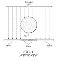
A current laser/sensor configuration of the assignee includes two sensors for each laser light source. The light from a laser is processed through optics to form a line or plane of collimated light. This light passes over the measured part and falls upon the two sensors, one for each side of the part. Each sensor is perpendicular to the collimated light such that one side of a shadow cast by the part falls on each of the two sensors. The sensors are placed as close together as possible but there is still typically a small gap between them. FIG. 1 illustrates this configuration.
Each sensor includes a photo sensor that measures the amount of light it receives. The wider the part, the less light reaches the sensor and vice versa. The correlation between light received and part width is calibrated allowing the part to be measured according to the size of the shadow on the sensors. Because the collimated light is perpendicular to the sensor, the width of the part's shadow cast on the sensors is the same as the width of the part.
FIG. 9 shows a prior art system of U.S. Pat. No. 5,608,530 wherein mirrors are used to change the direction of light passing by a part.
U.S. Pat. No. 4,923,066 discloses an automatic visual inspection system for small arms ammunition which sorts visual surface flaws at high speed according to established standards which can be tailored to fit specific needs.
U.S. Pat. No. 7,403,872 discloses a method and system for inspecting manufactured parts such as cartridges and cartridge cases and sorting the inspected parts.
WO 2005/022076 discloses a plurality of light line generators which generate associated beams of light that intersect a part to be inspected.
U.S. Pat. No. 6,313,948 discloses an optical beam shaper for production of a uniform sheet of light for use in a parts inspection system having a light source including a coherent light generator, a diffractive beam shaper, and lens elements.
U.S. Pat. No. 6,285,034 discloses an inspection system for evaluating rotationally asymmetric workpieces for conformance to configuration criteria.
U.S. Pat. No. 6,252,661 discloses an inspection system for evaluating workpieces for conformance to configuration criteria.
U.S. Pat. No. 6,959,108 discloses an inspection system wherein workpieces to be inspected are consecutively and automatically launched to pass unsupported through the field of view of a plurality of cameras.
U.S. Pat. No. 4,831,251 discloses an optical device for discriminating threaded workpiece by the handedness by their screw thread profiles.
U.S. Pat. No. 5,383,021 discloses a non-contact inspection system capable of evaluating spatial form parameters of a workpiece to provide inspection of parts in production.
U.S. Pat. No. 5,568,263 also discloses a non-contact inspection system capable of evaluating spatial form parameters of a workpiece to provide inspection of parts in production.
U.S. Pat. No. 4,852,983 discloses an optical system which simulates the optical effect of traveling over a large distance on light traveling between reference surfaces.
U.S. Patent Application Publication No. 2005/0174567 discloses a system to determine the presence of cracks in parts.
U.S. Patent Application Publication No. 2006/0236792 discloses an inspection station for a workpiece including a conveyor, a mechanism for rotating the workpiece, and a probe.
U.S. Pat. No. 6,289,600 discloses a non-contact measuring device for determining the dimensions of a cylindrical object, such as a pipe.
U.S. Pat. No. 5,521,707 discloses a non-contact laser-based sensor guided by a precision mechanical system to scan a thread form producing a set of digitized images of the thread form.
WO 2009/130062 discloses a method and a device for the optical viewing of objects.
U.S. Pat. Nos. 5,168,458 and 5,170,306 disclose methods and systems for gauging threaded fasteners to obtain trilobular parameters.
Other U.S. patent documents related to the invention include: U.S. Pat. Nos. 4,315,688; 4,598,998; 4,644,394; 4,852,983; 4,906,098; 5,521,707; 5,608,530; 5,646,724; 5,291,272; 6,055,329; 4,983,043; 3,924,953; 5,164,995; 4,721,388; 4,969,746; 5,012,117; 7,684,054; 7,403,872; 7,633,635; 7,312,607, 7,777,900; 7,633,046; 7,633,634; 7,738,121; 7,755,754; 7,738,088; 7,796,278; 8,054,460; 8,179,434 and U.S. published patent applications 2010/0245850, 2010/0201806, 2012/0293623; 2012/0105429; and 2012/0293789.
For purposes of this application and for clarity, the photo sensors or photodetectors of this application are drawn as rectangles implying that they are some kind of photocell. In reality, they can be any device that measures intensity of light. Some examples are:
Area (Photocell): This is a device that generates variable voltages depending on the amount of light it receives. It receives light over an area.
Line (Linear Sensor Array): Conceptually this is a linear array of photo sensors. Each photo sensor measures the intensity of a point of light and acts independently allowing the sensor to measure both the total amount of light and position of the light that it receives.
Point (Photodiode): A photo diode is functionally the same as a photocell except that it measures light that falls on a point (or essentially a point) rather than an area.
Both area and line sensors can be directly substituted for the sensor rectangles in the drawing figures of this application. Point light sensors require more processing. The light passing by the part must somehow be focused onto the point sensor. There are a variety of ways this can be done and one possible configuration is illustrated in FIG. 9. For clarity only one sensor on one side is shown in FIG. 9 though this can be repeated for all sensors.
SUMMARY OF EXAMPLE EMBODIMENTS
An object of at least one embodiment of the present invention is to increase the range of a geometric dimension of a part that can be optically determined in a high-resolution imaging and processing method and system.
In carrying out the above object and other objects of at least one embodiment of the present invention, a high-resolution imaging and processing method of increasing the range of a geometric dimension of a part that can be determined is provided. The method includes the steps of supporting a part having a width and directing at least one plane of collimated radiation in a sensing direction at a surface of the part. Each of the planes is occluded by the part to create unobstructed first and second planar portions of the plane of radiation passing by and not blocked by the supported part and to cast a radiation shadow of the supported part. Each of the first and second planar portions has a width and contains an amount of radiation which is representative of a respective geometric dimension of the supported part to be determined. The method also includes measuring the amount of radiation in each of the first and second planar portions imaged on first and second predetermined measuring areas, respectively, to determine the geometric dimension. The improvement includes increasing the width and decreasing the intensity of the first and second planar portions imaged on the first and second predetermined measuring areas, respectively, to obtain elongated first and second planar portions, respectively, and to produce first and second electrical signals, respectively. The improvement also includes providing third and fourth predetermined measuring areas adjacent the first and second predetermined measuring areas, respectively, to image at least a portion of the elongated first and second planar portions, respectively, thereon and to produce third and fourth electrical signals, respectively. The improvement further includes processing the first, second, third and fourth electrical signals to determine the geometric dimension with enhanced accuracy.
The first and third measuring areas may be staggered and the second and fourth measuring areas may be staggered.
The first and third measuring areas may be angled at a first angle with respect to the width of the part and the second and fourth measuring areas may be angled at the same second angle with respect to the width of the part.
The first and second angles may be substantially equal. The first and second measuring areas may be substantially perpendicular to each other and the third and fourth measuring areas may be substantially perpendicular to each other.
There may be substantially no gap between the first and second measuring areas on which to cast the radiation shadow.
The radiation may be laser radiation, visible radiation and/or light radiation.
Further in carrying out the above object and other objects of at least one embodiment of the present invention, a high-resolution imaging and processing system for increasing range of a geometric dimension of a part that can be determined in the system is provided. The system includes a support for supporting a part having a width along a measurement axis and at least one transmitter-receiver pair. Each pair includes a radiation source for directing a plane of collimated radiation at a surface of the part so that the part occludes each plane of radiation to create unobstructed first and second portions of the plane of radiation passing by and not blocked by the supported part and to cast a radiation shadow of the supported part. Each of the unobstructed first and second planar portions has a width and contains an amount of radiation which is representative of a respective geometric dimension of the part to be determined. Each pair also includes a receiver module for measuring the amount of radiation in the unobstructed first and second planar portions imaged on first and second predetermined measuring areas, respectively. The improvement includes means or mechanism for increasing the width and decreasing the intensity of the first and second planar portions imaged on the first and second predetermined measuring areas, respectively, to produce first and second electrical signals, respectively. Also included are third and fourth predetermined measuring areas, respectively, adjacent to the first and second measuring areas, respectively, to image at least a portion of the first and second planar portions, respectively, to produce third and fourth electrical signals, respectively. At least one processor processes the first, second, third and fourth electrical signals to determine the geometric dimension with enhanced accuracy.
The first and third measuring areas may be staggered and the second and fourth measuring areas may be staggered.
The first and third measuring areas may be angled at a first angle with respect to the width of the part and the second and fourth measuring areas may be angled at a second angle with respect to the width of the part.
The first and second angles may be substantially equal.
The first and second measuring areas may be substantially perpendicular to each other and the third and fourth measuring areas may be substantially perpendicular to each other.
Photodetectors may have each of the predetermined measuring areas.
The photodetectors may comprise at least one of photocells, linear sensor arrays and photodiodes.
The system may include an actuator mechanism for moving each pair in unison relative in the part to scan the part with each plane of radiation.
The radiation may be laser radiation, visible radiation and/or light radiation.
BRIEF DESCRIPTION OF THE DRAWINGS
For a more complete understanding of the present invention, and for further features and advantages thereof, reference is made to the following description taken in conjunction with the accompanying drawings, in which:
FIG. 1 is a top plan schematic view illustrating a method and prior art method and system for measuring a geometric dimension of a part;
FIG. 2 is a top plan schematic view illustrating a method and system for determining a geometric dimension of a part utilizing at least one embodiment of the present invention;
FIG. 3 is a top plan schematic view of a cylindrical part illuminated with collimated light and a pair of angled photo sensors or detectors of at least one embodiment of the present invention;
FIG. 4a is a top plan schematic view, partially broken away, of a part and collimated radiation with a non-rotated sensor;
FIG. 4b shows a dimension of the part and shadow cast on an angled sensor with associated calculations;
FIG. 5 is a top plan schematic view of another embodiment for spreading or magnifying collimated light passing by a part;
FIG. 6 is a top plan schematic view of yet another embodiment wherein the sensor is substantially parallel to the generated collimated light;
FIG. 7 is a top plan schematic view of yet another embodiment wherein the angled sensors are staggered;
FIG. 8 is a view similar to the view of FIG. 7 wherein two adjacent sensors overlap in the shadow cast by the part to eliminate any gap between the sensors; and
FIG. 9 is a top plan schematic view of a prior art point sensor system.
DETAILED DESCRIPTION
As required, detailed embodiments of the present invention are disclosed herein; however, it is to be understood that the disclosed embodiments are merely exemplary of the invention that may be embodied in various and alternative forms. The figures are not necessarily to scale; some features may be exaggerated or minimized to show details of particular components. Therefore, specific structural and functional details disclosed herein are not to be interpreted as limiting, but merely as a representative basis for teaching one skilled in the art to variously employ the present invention.
In general, and as described below, at least one embodiment of the present invention provides a high-resolution imaging and processing method and system for determining a geometric dimension of a part such as a manufactured part. The part, such as a threaded fastener, has a length, a width, a part axis and an outer peripheral surface which extends 360° around the part.
Referring now to FIG. 2, a part such as a threaded bolt may be supported by a chuck or fixture of a part holder, as described in detail in U.S. Pat. No. 7,812,970. The head of the bolt is supported by and disposed within the fixture. The threads of the bolt may be optically inspected in an embodiment of the method and system of the present invention. Other parts, such as ammunition cases can be supported in a similar or slightly different fashion. Alternatively, such parts can travel down a track and the rest of the system can be stationary.
As shown in FIG. 2, the system includes at least one transmitter-receiver pair, and preferably, a plurality of such pairs. Each pair includes a radiation source for directing a plane of collimated radiation at the supported part so that the part occludes each plane of radiation to create unobstructed first and second planar portions of the plane of radiation passing by and not blocked by the supported part. Each of the unobstructed first and second planar portions has a width and contains an amount of radiation which is representative of a respective geometric dimension of the part to be determined. Each pair further also includes a receiver module for measuring the amount of radiation present in each of the unobstructed first and second planar portions imaged on first and second predetermined measuring areas, respectively, to determine the geometric dimension.
The system may further include an actuator mechanism such as a linear drive under control of a system controller for moving an optical head and each supported transmitter-receiver pair in unison relative to the supported part to scan the at least one plane of collimated radiation in a scanning direction at a surface of the part. However, it is to be understood that the supported part may move relative to the transmitter-receiver pair. For example, the part may travel down a track relative to stationary transmitter-receiver pairs.
The system may further include one or more processors under control of the system controller to process the resulting sets of 2-D profile signals to obtain measurements of the parts as described in U.S. Pat. No. 7,812,970. As shown in FIG. 2, the system may also include sensors including a linear encoder, a user interface and a display as described in U.S. Pat. No. 7,812,970.
There are at least two types of improvements to the methods and systems of the prior art described herein:
1) Improvements to magnify (or spread out) the image of the part. Magnifying or splitting the image of a part allows measurements to be calculated more accurately.
2) Improvements to increase the area covered by sensors. The effective sizes of the photo sensors or detectors are increased to accommodate such magnified or split part images.
Sensor Design Improvements to Magnify Part Images
A new sensor design is best described in multiple parts because each part adds an improvement to the sensor design. Each of the parts can be implemented separately but may be combined in a single design as described herein.
At least one embodiment of the present invention increases the sensitivity of the laser sensors. The current sensor design measures using a 1:1 part-width-to-shadow ratio. By increasing the ratio (i.e. magnifying the image) to 1:X (x>1) the shadow of the part will be magnified so that small details in the part will produce large details in the part's shadow. This will allow the sensors to produce more accurate and consistent measurements.
There are multiple ways in which the (shadow) image of a part can be magnified in a way that is suitable for detailed measurements.
Using Angled Photo Sensors or Detectors
The design change is to rotate the sensors so that they are at a more than 90 degree angle to the collimated light. This has the effect of elongating (magnifying) the shadow as illustrated in FIG. 3.
FIG. 3 illustrates the angle as rotated 45 degrees from perpendicular. However, a rotation of any angle will magnify the shadow. The more the sensor is rotated the more the shadow is multiplied though there are obvious problems as the rotation angle approaches 90 degrees.
Calculations show that the amount of shadow magnification is 1/cos (rotation angle). This is illustrated in FIGS. 4a and 4 b.
The following table shows some example angle vs. magnification for selected angles.
Angle (degrees) Magnification
30 1.15
45 1.41
60 2.0

Using Optics
This method of magnifying a part image uses optical elements in the form of lenses. The image of the part passes through a magnifying lens and then to a suitable sensor or sensors. FIG. 5 illustrates this configuration. For clarity only one side of the sensor configuration is shown in FIG. 5.
Combinations
The previous image magnification methods can be combined in any order to increase the magnification. FIG. 6 illustrates one possible combined configuration. In FIG. 6, the image of the part is magnified 2× by angling the mirror (assuming a rotation of 60 degrees) plus an additional magnification from the magnifying lens.
A gist of at least one embodiment of the present invention is to spread out (magnify) at least one laser line segment or plane of collimated radiation so it can be measured in greater detail using multiple photo-diodes. Magnification of the line segment can be done either by angling mirrors/detectors or through the use of magnifying optics. It is not strictly necessary to magnify the line segment in order to use multiple photo-diodes. The line segment could simply be split into multiple sub-segments and each sub-segments sent to a photo-diode. In this embodiment, multiple photo-diodes are used in order to measure with greater resolution.
Photo Sensor or Detector Design Improvements to Increase Measurement Width
The above-described improvements increase the measurement capacity of receiver modules which include sensors or photodiodes by allowing wider parts to be measured.
Angling the sensors has the benefit of increasing the sensitivity of the sensor by magnifying the shadow but has the downside of reducing the effective width of the sensor. The following table shows the magnitude of this effect for selected angles.
Angle (degrees) Effective Width Reduction Factor
30 0.87
45 0.71
60 0.50
Rotating the sensor 60 degrees doubles the sensitivity but also cuts in half the maximum width of parts that can be measured.
One solution to this is to use multiple sensors that are staggered to increase the width of shadows that can be measured. This is illustrated in FIG. 7.
Staggering the sensors causes the shadow of the part to spill over to a lower adjacent sensor if it is wider than the previous sensor. The electrical signal outputs from the sensors are added together to form the net measurement. Any number of sensors can be combined in the staggered formation allowing the maximum width of measureable parts to be limited only by the number of staggered sensors rather than the width of a single sensor.
Photo Sensor or Detector Design Improvement to Eliminate the “Gap” Between Sensors
This improvement increases the measurement capacity of the sensor by allowing narrower parts to be measured.
The prior art typically includes a gap between adjacent photo sensors or detectors. This imposes a lower limit on the size of parts that can be measured. However, this gap can be eliminated by moving the left and right sensors so that they overlap with respect to the parts as shown in FIG. 8. By overlapping the sensors the lower limit is eliminated so the optical instrument will be able to measure any part that can be placed such that each side of its shadow falls on each side of the sensors.
Because the sensors are overlapped there is no gap between for the sensors. All parts of the shadow must fall on the sensors. However, the part is only measureable if one side of the part falls on each side of the sensors.
SUMMARY
This application describes improvements for photo sensors and/or detectors used in various inspection and sorting instruments. Multiple improvements can be implemented in any combination or together for maximum benefit. These improvements include:
1) Angle the sensors with respect to the collimated light. This increases measurement resolution by magnifying or spreading out the collimated light. The collimated light can also be optically magnified. Also, the collimated light can be optically split and imaged on multiple photo detectors.
2) Use multiple sensors in a staggered formation to extend the maximum size of a part that can be measured.
3) Overlap the sensors on each side to eliminate the present gap between sensors. With this change there is no lower limit to the width of parts that can be measured.
While exemplary embodiments are described above, it is not intended that these embodiments describe all possible forms of the invention. Rather, the words used in the specification are words of description rather than limitation, and it is understood that various changes may be made without departing from the spirit and scope of the invention. Additionally, the features of various implementing embodiments may be combined to form further embodiments of the invention.

Claims (20)

What is claimed is:
1. A high-resolution imaging and processing method of increasing the range of a geometric dimension of a part that can be determined, the method including the steps of supporting with a support a part having a width, directing from at least one radiation source at least one plane of collimated radiation in a sensing direction at a surface of the part, wherein each of the planes is occluded by the part to create unobstructed first and second planar portions of the plane of radiation passing by and not blocked by the supported part and to cast a radiation shadow of the supported part, wherein each of the first and second planar portions has a width and contains an amount of radiation which is representative of a respective geometric dimension of the supported part to be determined, and measuring by a receiver module the amount of radiation in each of the first and second planar portions imaged on first and second predetermined measuring areas, respectively, to determine the geometric dimension, the improvement comprising:
utilizing at least one optical component to increase the width and decrease the intensity of the first and second planar portions imaged on the first and second predetermined measuring areas, respectively, to obtain elongated first and second planar portions, respectively, and to produce first and second electrical signals, respectively;
providing third and fourth predetermined measuring areas adjacent the first and second predetermined measuring areas, respectively, to image at least a portion of the elongated first and second planar portions, respectively, thereon and to produce third and fourth electrical signals, respectively; and
processing by at least one processor the first, second, third and fourth electrical signals to determine the geometric dimension with enhanced accuracy.
2. The method as claimed in claim 1, wherein the first and third measuring areas are staggered and the second and fourth measuring areas are staggered.
3. The method as claimed in claim 1, wherein the first and third measuring areas are angled at a first angle with respect to the width of the part and the second and fourth measuring areas are angled at the same second angle with respect to the width of the part.
4. The method as claimed in claim 3, wherein the first and second angles are substantially equal.
5. The method as claimed in claim 1, wherein the first and second measuring areas are substantially perpendicular to each other and wherein the third and fourth measuring areas are substantially perpendicular to each other.
6. The method as claimed in claim 1, wherein there is substantially no gap between the first and second measuring areas on which to cast the radiation shadow.
7. The method as claimed in claim 1, wherein the radiation is laser radiation.
8. The method as claimed in claim 1, wherein the radiation is visible radiation.
9. The method as claimed in claim 1, wherein the radiation is light radiation.
10. A high-resolution imaging and processing system for increasing range of a geometric dimension of a part that can be determined in the system, the system including a support for supporting a part having a width and at least one transmitter-receiver pair, each pair including a radiation source for directing a plane of collimated radiation at a surface of the part so that the part occludes each plane of radiation to create unobstructed first and second portions of the plane of radiation passing by and not blocked by the supported part and to cast a radiation shadow of the supported part, wherein each of the unobstructed first and second planar portions has a width and contains an amount of radiation which is representative of a respective geometric dimension of the part to be determined, each pair also including a receiver module for measuring the amount of radiation in the unobstructed first and second planar portions imaged on first and second predetermined measuring areas, respectively, the improvement comprising:
at least one optical component to increase the width and decrease the intensity of the first and second planar portions imaged on the first and second predetermined measuring areas, respectively, to produce first and second electrical signals, respectively;
third and fourth predetermined measuring areas, respectively, adjacent to the first and second measuring areas, respectively, to image at least a portion of the first and second planar portions, respectively, to produce third and fourth electrical signals, respectively; and
at least one processor to process the first, second, third and fourth electrical signals to determine the geometric dimension with enhanced accuracy.
11. The system as claimed in claim 10, wherein the first and third measuring areas are staggered and the second and fourth measuring areas are staggered.
12. The system as claimed in claim 10, wherein the first and third measuring areas are angled at a first angle with respect to the width of the part and the second and fourth measuring areas are angled at a second angle with respect to the width of the part.
13. The system as claimed in claim 12, wherein the first and second angles are substantially equal.
14. The system as claimed in claim 10, wherein the first and second measuring areas are substantially perpendicular to each other and wherein the third and fourth measuring areas are substantially perpendicular to each other.
15. The system as claimed in claim 10, wherein photodetectors have each of the predetermined measuring areas.
16. The system as claimed in claim 15, wherein the photodetectors comprise at least one of photocells, linear sensor arrays and photodiodes.
17. The system as claimed in claim 10 further comprising an actuator mechanism for moving each pair in unison relative to the part to scan the part with each plane of radiation.
18. The system as claimed in claim 10, wherein the radiation is laser radiation.
19. The system as claimed in claim 10, wherein the radiation is visible radiation.
20. The system as claimed in claim 10, wherein the radiation is light radiation.
US13/972,194 2013-08-21 2013-08-21 High-resolution imaging and processing method and system for increasing the range of a geometric dimension of a part that can be determined Active 2034-10-03 US9377297B2 (en)

Priority Applications (2)

Application Number Priority Date Filing Date Title
US13/972,194 US9377297B2 (en) 2013-08-21 2013-08-21 High-resolution imaging and processing method and system for increasing the range of a geometric dimension of a part that can be determined
PCT/US2014/035626 WO2015026406A2 (en) 2013-08-21 2014-04-28 High-resolution imaging and processing method and system for increasing the range of a geometric dimension of a part that can be determined

Applications Claiming Priority (1)

Application Number Priority Date Filing Date Title
US13/972,194 US9377297B2 (en) 2013-08-21 2013-08-21 High-resolution imaging and processing method and system for increasing the range of a geometric dimension of a part that can be determined

Publications (2)

Publication Number Publication Date
US20150055145A1 US20150055145A1 (en) 2015-02-26
US9377297B2 true US9377297B2 (en) 2016-06-28

Family

ID=52480096

Family Applications (1)

Application Number Title Priority Date Filing Date
US13/972,194 Active 2034-10-03 US9377297B2 (en) 2013-08-21 2013-08-21 High-resolution imaging and processing method and system for increasing the range of a geometric dimension of a part that can be determined

Country Status (2)

Country Link
US (1) US9377297B2 (en)
WO (1) WO2015026406A2 (en)

Cited By (3)

* Cited by examiner, † Cited by third party
Publication number Priority date Publication date Assignee Title
US11045842B2 (en) 2019-05-16 2021-06-29 General Inspection, Llc Method and system for inspecting unidentified mixed parts at an inspection station having a measurement axis to identify the parts
US11162906B2 (en) 2019-05-16 2021-11-02 General Inspection, Llc High-speed method and system for inspecting and sorting a stream of unidentified mixed parts
US11543364B2 (en) 2019-05-16 2023-01-03 General Inspection, Llc Computer-implemented method of automatically generating inspection templates of a plurality of known good fasteners

Citations (52)

* Cited by examiner, † Cited by third party
Publication number Priority date Publication date Assignee Title
US3924953A (en) 1974-12-18 1975-12-09 Us Navy Helix pitch monitor
US4315688A (en) 1979-08-08 1982-02-16 Diffracto Ltd. Electro-optical sensor systems for thread and hole inspection
US4598998A (en) 1982-02-25 1986-07-08 Sumitomo Kinzoku Kogyo Kabushiki Kaisha Screw surface flaw inspection method and an apparatus therefor
US4644394A (en) 1985-12-31 1987-02-17 Dale Reeves Apparatus for inspecting an externally threaded surface of an object
US4721388A (en) 1984-10-05 1988-01-26 Hitachi, Ltd. Method of measuring shape of object in non-contacting manner
US4831251A (en) 1988-04-18 1989-05-16 Mectron Engineering Company, Inc. Right and left-hand screw thread optical discriminator
US4852983A (en) 1987-09-21 1989-08-01 Spectra-Physics, Inc. Distance simulator
US4906098A (en) 1988-05-09 1990-03-06 Glass Technology Development Corporation Optical profile measuring apparatus
US4923066A (en) 1987-10-08 1990-05-08 Elor Optronics Ltd. Small arms ammunition inspection system
US4969746A (en) 1988-09-02 1990-11-13 R. J. Reynolds Tobacco Company Component inspection apparatus and method
US5012117A (en) 1988-09-15 1991-04-30 Alfred Teves Gmbh Process and apparatus for the automatic non-contact surface inspection of cylindrical parts
US5142559A (en) 1990-05-11 1992-08-25 The Research Foundation Of State University Of New York Radiation detection system including radiation alignment means and isocentrically rotatable detectors
US5164995A (en) 1989-11-27 1992-11-17 General Motors Corporation Signature analysis apparatus
US5168458A (en) 1990-03-16 1992-12-01 Research Engineering & Manufacturing, Inc. Method and apparatus for gaging the degree of lobulation of bodies such as threaded fasteners
US5170306A (en) 1990-03-16 1992-12-08 Research Engineering & Manufacturing, Inc. Method and apparatus for gaging the geometry of point threads and other special threads
US5291272A (en) 1991-09-27 1994-03-01 Criterion Resources, Inc. Method and apparatus for measuring dimensional variables of threaded pipe
US5383021A (en) 1993-04-19 1995-01-17 Mectron Engineering Company Optical part inspection system
US5521707A (en) 1991-08-21 1996-05-28 Apeiron, Inc. Laser scanning method and apparatus for rapid precision measurement of thread form
US5608530A (en) 1994-08-08 1997-03-04 General Inspection, Inc. Inspection device for measuring a geometric dimension of a part
US5646724A (en) 1995-08-18 1997-07-08 Candid Logic, Inc. Threaded parts inspection device
US6055329A (en) 1994-06-09 2000-04-25 Sherikon, Inc. High speed opto-electronic gage and method for gaging
US6252661B1 (en) 1999-08-02 2001-06-26 James L. Hanna Optical sub-pixel parts inspection system
US6285034B1 (en) 1998-11-04 2001-09-04 James L. Hanna Inspection system for flanged bolts
US6289600B1 (en) 1999-11-02 2001-09-18 United States Pipe & Foundry Company Non-contact measuring device
US6313948B1 (en) 1999-08-02 2001-11-06 James I. Hanna Optical beam shaper
WO2005022076A2 (en) 2003-08-23 2005-03-10 General Inspection, Llc Part inspection apparatus
US20050174567A1 (en) 2004-02-09 2005-08-11 Mectron Engineering Company Crack detection system
US20050213113A1 (en) 2004-03-25 2005-09-29 Harald Sikora Method for measuring the dimension of a non-circular cross-section of an elongated article in particular of a flat cable or a sector cable
US6959108B1 (en) 2001-12-06 2005-10-25 Interactive Design, Inc. Image based defect detection system
US20060236792A1 (en) 2005-04-22 2006-10-26 Mectron Engineering Company Workpiece inspection system
US7312607B2 (en) 2004-07-20 2007-12-25 General Inspection Llc Eddy current part inspection system
US7403872B1 (en) 2007-04-13 2008-07-22 Gii Acquisition, Llc Method and system for inspecting manufactured parts and sorting the inspected parts
US20090103107A1 (en) 2007-10-23 2009-04-23 Gii Acquisition, Llc Dba General Inspection, Llc Method And System For Inspecting Parts Utilizing Triangulation
WO2009130062A1 (en) 2008-04-24 2009-10-29 Claudio Sedazzari A method and a device for optical viewing of objects
US7633634B2 (en) 2007-10-23 2009-12-15 Gii Acquisition, Llc Optical modules and method of precisely assembling same
US7633635B2 (en) 2006-08-07 2009-12-15 GII Acquisitions, LLC Method and system for automatically identifying non-labeled, manufactured parts
US7633046B2 (en) 2007-10-23 2009-12-15 Gii Acquisition Llc Method for estimating thread parameters of a part
US7684054B2 (en) 2006-08-25 2010-03-23 Gii Acquisition, Llc Profile inspection system for threaded and axial components
US7738088B2 (en) 2007-10-23 2010-06-15 Gii Acquisition, Llc Optical method and system for generating calibration data for use in calibrating a part inspection system
US7738121B2 (en) 2007-10-23 2010-06-15 Gii Acquisition, Llc Method and inspection head apparatus for optically measuring geometric dimensions of a part
US7755754B2 (en) 2007-10-23 2010-07-13 Gii Acquisition, Llc Calibration device for use in an optical part measuring system
US20100201806A1 (en) 2007-10-23 2010-08-12 Gii Acquisition, Llc Dba General Inspection, Llc Method and system for automatically inspecting parts and for automatically generating calibration data for use in inspecting parts
US7777900B2 (en) 2007-10-23 2010-08-17 Gii Acquisition, Llc Method and system for optically inspecting parts
US20100207989A1 (en) 2009-02-19 2010-08-19 Alexander Govyadinov Light-scattering drop detector
US7796278B2 (en) 2008-09-19 2010-09-14 Gii Acquisition, Llc Method for precisely measuring position of a part to be inspected at a part inspection station
US20100245850A1 (en) 2009-03-27 2010-09-30 Gii Acquisition, Llc Dba General Inspection, Llc System For Indirectly Measuring A Geometric Dimension Related To An Opening In An Apertured Exterior Surface of A Part Based On Direct Measurements Of The Part When Fixtured At A Measurement Station
US7920278B2 (en) 2007-10-23 2011-04-05 Gii Acquisition, Llc Non-contact method and system for inspecting parts
US8054460B2 (en) 2008-05-12 2011-11-08 GM Global Technology Operations LLC Methodology for evaluating the start and profile of a thread with a vision-based system
US20120105429A1 (en) 2010-10-29 2012-05-03 Gii Acquisition, Llc Dba General Inspection, Llc Method and system for high-speed, high-resolution 3-d imaging of manufactured parts of various sizes
US8179434B2 (en) 2008-05-09 2012-05-15 Mettler-Toledo, LLC System and method for imaging of curved surfaces
US20120293789A1 (en) 2011-05-17 2012-11-22 Gii Acquisition, Llc Dba General Inspection, Llc Method and system for optically inspecting parts
US20120293623A1 (en) 2011-05-17 2012-11-22 Gii Acquisition, Llc Dba General Inspection, Llc Method and system for inspecting small manufactured objects at a plurality of inspection stations and sorting the inspected objects

Patent Citations (54)

* Cited by examiner, † Cited by third party
Publication number Priority date Publication date Assignee Title
US3924953A (en) 1974-12-18 1975-12-09 Us Navy Helix pitch monitor
US4315688A (en) 1979-08-08 1982-02-16 Diffracto Ltd. Electro-optical sensor systems for thread and hole inspection
US4598998A (en) 1982-02-25 1986-07-08 Sumitomo Kinzoku Kogyo Kabushiki Kaisha Screw surface flaw inspection method and an apparatus therefor
US4721388A (en) 1984-10-05 1988-01-26 Hitachi, Ltd. Method of measuring shape of object in non-contacting manner
US4644394A (en) 1985-12-31 1987-02-17 Dale Reeves Apparatus for inspecting an externally threaded surface of an object
US4852983A (en) 1987-09-21 1989-08-01 Spectra-Physics, Inc. Distance simulator
US4923066A (en) 1987-10-08 1990-05-08 Elor Optronics Ltd. Small arms ammunition inspection system
US4831251A (en) 1988-04-18 1989-05-16 Mectron Engineering Company, Inc. Right and left-hand screw thread optical discriminator
US4906098A (en) 1988-05-09 1990-03-06 Glass Technology Development Corporation Optical profile measuring apparatus
US4969746A (en) 1988-09-02 1990-11-13 R. J. Reynolds Tobacco Company Component inspection apparatus and method
US5012117A (en) 1988-09-15 1991-04-30 Alfred Teves Gmbh Process and apparatus for the automatic non-contact surface inspection of cylindrical parts
US5164995A (en) 1989-11-27 1992-11-17 General Motors Corporation Signature analysis apparatus
US5168458A (en) 1990-03-16 1992-12-01 Research Engineering & Manufacturing, Inc. Method and apparatus for gaging the degree of lobulation of bodies such as threaded fasteners
US5170306A (en) 1990-03-16 1992-12-08 Research Engineering & Manufacturing, Inc. Method and apparatus for gaging the geometry of point threads and other special threads
US5142559A (en) 1990-05-11 1992-08-25 The Research Foundation Of State University Of New York Radiation detection system including radiation alignment means and isocentrically rotatable detectors
US5521707A (en) 1991-08-21 1996-05-28 Apeiron, Inc. Laser scanning method and apparatus for rapid precision measurement of thread form
US5291272A (en) 1991-09-27 1994-03-01 Criterion Resources, Inc. Method and apparatus for measuring dimensional variables of threaded pipe
US5383021A (en) 1993-04-19 1995-01-17 Mectron Engineering Company Optical part inspection system
US5568263A (en) 1993-04-19 1996-10-22 Mectron Engineering Company Non-contact inspection system
US6055329A (en) 1994-06-09 2000-04-25 Sherikon, Inc. High speed opto-electronic gage and method for gaging
US5608530A (en) 1994-08-08 1997-03-04 General Inspection, Inc. Inspection device for measuring a geometric dimension of a part
US5646724A (en) 1995-08-18 1997-07-08 Candid Logic, Inc. Threaded parts inspection device
US6285034B1 (en) 1998-11-04 2001-09-04 James L. Hanna Inspection system for flanged bolts
US6252661B1 (en) 1999-08-02 2001-06-26 James L. Hanna Optical sub-pixel parts inspection system
US6313948B1 (en) 1999-08-02 2001-11-06 James I. Hanna Optical beam shaper
US6289600B1 (en) 1999-11-02 2001-09-18 United States Pipe & Foundry Company Non-contact measuring device
US6959108B1 (en) 2001-12-06 2005-10-25 Interactive Design, Inc. Image based defect detection system
WO2005022076A2 (en) 2003-08-23 2005-03-10 General Inspection, Llc Part inspection apparatus
US20050174567A1 (en) 2004-02-09 2005-08-11 Mectron Engineering Company Crack detection system
US20050213113A1 (en) 2004-03-25 2005-09-29 Harald Sikora Method for measuring the dimension of a non-circular cross-section of an elongated article in particular of a flat cable or a sector cable
US7312607B2 (en) 2004-07-20 2007-12-25 General Inspection Llc Eddy current part inspection system
US20060236792A1 (en) 2005-04-22 2006-10-26 Mectron Engineering Company Workpiece inspection system
US7633635B2 (en) 2006-08-07 2009-12-15 GII Acquisitions, LLC Method and system for automatically identifying non-labeled, manufactured parts
US7684054B2 (en) 2006-08-25 2010-03-23 Gii Acquisition, Llc Profile inspection system for threaded and axial components
US7403872B1 (en) 2007-04-13 2008-07-22 Gii Acquisition, Llc Method and system for inspecting manufactured parts and sorting the inspected parts
US7633634B2 (en) 2007-10-23 2009-12-15 Gii Acquisition, Llc Optical modules and method of precisely assembling same
US20090103107A1 (en) 2007-10-23 2009-04-23 Gii Acquisition, Llc Dba General Inspection, Llc Method And System For Inspecting Parts Utilizing Triangulation
US7633046B2 (en) 2007-10-23 2009-12-15 Gii Acquisition Llc Method for estimating thread parameters of a part
US7812970B2 (en) 2007-10-23 2010-10-12 Gii Acquisition, Llc Method and system for inspecting parts utilizing triangulation
US7738088B2 (en) 2007-10-23 2010-06-15 Gii Acquisition, Llc Optical method and system for generating calibration data for use in calibrating a part inspection system
US7738121B2 (en) 2007-10-23 2010-06-15 Gii Acquisition, Llc Method and inspection head apparatus for optically measuring geometric dimensions of a part
US7755754B2 (en) 2007-10-23 2010-07-13 Gii Acquisition, Llc Calibration device for use in an optical part measuring system
US20100201806A1 (en) 2007-10-23 2010-08-12 Gii Acquisition, Llc Dba General Inspection, Llc Method and system for automatically inspecting parts and for automatically generating calibration data for use in inspecting parts
US7777900B2 (en) 2007-10-23 2010-08-17 Gii Acquisition, Llc Method and system for optically inspecting parts
US7920278B2 (en) 2007-10-23 2011-04-05 Gii Acquisition, Llc Non-contact method and system for inspecting parts
WO2009130062A1 (en) 2008-04-24 2009-10-29 Claudio Sedazzari A method and a device for optical viewing of objects
US8179434B2 (en) 2008-05-09 2012-05-15 Mettler-Toledo, LLC System and method for imaging of curved surfaces
US8054460B2 (en) 2008-05-12 2011-11-08 GM Global Technology Operations LLC Methodology for evaluating the start and profile of a thread with a vision-based system
US7796278B2 (en) 2008-09-19 2010-09-14 Gii Acquisition, Llc Method for precisely measuring position of a part to be inspected at a part inspection station
US20100207989A1 (en) 2009-02-19 2010-08-19 Alexander Govyadinov Light-scattering drop detector
US20100245850A1 (en) 2009-03-27 2010-09-30 Gii Acquisition, Llc Dba General Inspection, Llc System For Indirectly Measuring A Geometric Dimension Related To An Opening In An Apertured Exterior Surface of A Part Based On Direct Measurements Of The Part When Fixtured At A Measurement Station
US20120105429A1 (en) 2010-10-29 2012-05-03 Gii Acquisition, Llc Dba General Inspection, Llc Method and system for high-speed, high-resolution 3-d imaging of manufactured parts of various sizes
US20120293789A1 (en) 2011-05-17 2012-11-22 Gii Acquisition, Llc Dba General Inspection, Llc Method and system for optically inspecting parts
US20120293623A1 (en) 2011-05-17 2012-11-22 Gii Acquisition, Llc Dba General Inspection, Llc Method and system for inspecting small manufactured objects at a plurality of inspection stations and sorting the inspected objects

Non-Patent Citations (2)

* Cited by examiner, † Cited by third party
Title
International Preliminary Report on Patentability; corresponding international application No. PCT/US2014/035626; date of issuance of report Feb. 23, 2016.
International Search Report and Written Opinion; corresponding international application No. PCT/US2014/035626; date of mailing Mar. 10, 2015.

Cited By (4)

* Cited by examiner, † Cited by third party
Publication number Priority date Publication date Assignee Title
US11045842B2 (en) 2019-05-16 2021-06-29 General Inspection, Llc Method and system for inspecting unidentified mixed parts at an inspection station having a measurement axis to identify the parts
US11162906B2 (en) 2019-05-16 2021-11-02 General Inspection, Llc High-speed method and system for inspecting and sorting a stream of unidentified mixed parts
US11543364B2 (en) 2019-05-16 2023-01-03 General Inspection, Llc Computer-implemented method of automatically generating inspection templates of a plurality of known good fasteners
US11623250B2 (en) 2019-05-16 2023-04-11 General Inspection, Llc Method and system for sorting inspected parts

Also Published As

Publication number Publication date
US20150055145A1 (en) 2015-02-26
WO2015026406A2 (en) 2015-02-26
WO2015026406A3 (en) 2015-05-07

Similar Documents

Publication Publication Date Title
US11199395B2 (en) Profile inspection system for threaded and axial components
US8390826B2 (en) Method and system for optically inspecting parts
US7385710B1 (en) Measuring device
US9372077B2 (en) High-resolution imaging and processing method and system for determining a geometric dimension of a part
EP3165872B1 (en) Compensation of light intensity across a line of light providing improved measuring quality
CN104198055B (en) A kind of wavefront sensing device
US10207297B2 (en) Method and system for inspecting a manufactured part at an inspection station
CN106767545A (en) A kind of high accuracy high-space resolution angel measuring instrument and angle measurement method
US20140346094A1 (en) High-speed, triangulation-based, 3-d method and system for inspecting manufactured parts and sorting the inspected parts
US20150177160A1 (en) Non-Imaging Coherent Line Scanner Systems and Methods for Optical Inspection
EP1795862B1 (en) Method for measuring thickness of transparent objects
US9377297B2 (en) High-resolution imaging and processing method and system for increasing the range of a geometric dimension of a part that can be determined
US20160018214A1 (en) Inspection System for Threaded Parts
CN101063663B (en) Optical sensor and method for optically inspecting surfaces
US7869034B2 (en) Multi-angle and multi-channel inspecting device
JP2015017837A (en) Three-dimensional shape measurement device
RU2366894C2 (en) Laser device for measurement of instability of spatial position of objects and detection of their shape deviation from linearity
JP2007240168A (en) Inspection apparatus
US11163072B2 (en) Device for contactlessly determining the straightness of at least one long product and method for calibrating a device of this type
KR101881752B1 (en) defect sensing module based on line-beam and defect sensing device using its arrays for detection of the defects on surface
CN110243760A (en) Line domain domain optical coherence tomographic system and its longitudinal coordinate scaling method
EP2645054B1 (en) Light source apparatus for diameter-measuring instrument
US9217633B2 (en) Inspection arrangement
TW201321742A (en) Optical system
JP2009042128A (en) Height measuring device

Legal Events

Date Code Title Description
AS Assignment

Owner name: GII ACQUISITION, LLC DBA GENERAL INSPECTION, LLC,

Free format text: ASSIGNMENT OF ASSIGNORS INTEREST;ASSIGNORS:FLEMING, CHRISTOPHER C.;NYGAARD, MICHAEL G.;REEL/FRAME:031053/0229

Effective date: 20130820

STCF Information on status: patent grant

Free format text: PATENTED CASE

MAFP Maintenance fee payment

Free format text: PAYMENT OF MAINTENANCE FEE, 4TH YR, SMALL ENTITY (ORIGINAL EVENT CODE: M2551); ENTITY STATUS OF PATENT OWNER: SMALL ENTITY

Year of fee payment: 4

MAFP Maintenance fee payment

Free format text: PAYMENT OF MAINTENANCE FEE, 8TH YR, SMALL ENTITY (ORIGINAL EVENT CODE: M2552); ENTITY STATUS OF PATENT OWNER: SMALL ENTITY

Year of fee payment: 8