US9388374B2 - Microfluidic cell culture systems - Google Patents
Microfluidic cell culture systems Download PDFInfo
- Publication number
- US9388374B2 US9388374B2 US13/011,857 US201113011857A US9388374B2 US 9388374 B2 US9388374 B2 US 9388374B2 US 201113011857 A US201113011857 A US 201113011857A US 9388374 B2 US9388374 B2 US 9388374B2
- Authority
- US
- United States
- Prior art keywords
- flow
- culture
- culture chamber
- cells
- cell
- Prior art date
- Legal status (The legal status is an assumption and is not a legal conclusion. Google has not performed a legal analysis and makes no representation as to the accuracy of the status listed.)
- Active
Links
- 238000004113 cell culture Methods 0.000 title description 85
- 230000010412 perfusion Effects 0.000 claims abstract description 99
- 230000004888 barrier function Effects 0.000 claims abstract description 46
- 239000002609 medium Substances 0.000 claims description 27
- 238000011068 loading method Methods 0.000 claims description 25
- 239000012530 fluid Substances 0.000 claims description 20
- 238000009792 diffusion process Methods 0.000 claims description 13
- 239000001963 growth medium Substances 0.000 claims description 12
- 239000011521 glass Substances 0.000 claims description 11
- 239000011159 matrix material Substances 0.000 claims description 9
- 238000004891 communication Methods 0.000 claims description 6
- 238000011049 filling Methods 0.000 claims description 4
- 238000009630 liquid culture Methods 0.000 claims description 2
- 210000004027 cell Anatomy 0.000 description 212
- 108091006146 Channels Proteins 0.000 description 81
- 239000000499 gel Substances 0.000 description 57
- 238000013461 design Methods 0.000 description 42
- 239000007788 liquid Substances 0.000 description 38
- 230000005484 gravity Effects 0.000 description 30
- 238000000034 method Methods 0.000 description 29
- 239000003570 air Substances 0.000 description 25
- 239000010410 layer Substances 0.000 description 17
- NIXOWILDQLNWCW-UHFFFAOYSA-N acrylic acid group Chemical group C(C=C)(=O)O NIXOWILDQLNWCW-UHFFFAOYSA-N 0.000 description 16
- 239000007789 gas Substances 0.000 description 16
- 238000003556 assay Methods 0.000 description 14
- 239000004809 Teflon Substances 0.000 description 13
- 229920006362 Teflon® Polymers 0.000 description 13
- 239000003153 chemical reaction reagent Substances 0.000 description 12
- 238000003384 imaging method Methods 0.000 description 12
- 230000001413 cellular effect Effects 0.000 description 11
- 239000000243 solution Substances 0.000 description 11
- 238000004458 analytical method Methods 0.000 description 10
- 238000004519 manufacturing process Methods 0.000 description 10
- 230000006870 function Effects 0.000 description 9
- 230000007774 longterm Effects 0.000 description 9
- 239000000463 material Substances 0.000 description 9
- 230000007246 mechanism Effects 0.000 description 9
- 239000007787 solid Substances 0.000 description 9
- 239000004205 dimethyl polysiloxane Substances 0.000 description 8
- 235000013870 dimethyl polysiloxane Nutrition 0.000 description 8
- 238000002474 experimental method Methods 0.000 description 8
- 230000008901 benefit Effects 0.000 description 7
- 238000010586 diagram Methods 0.000 description 7
- 239000002245 particle Substances 0.000 description 7
- 239000000758 substrate Substances 0.000 description 7
- 230000002209 hydrophobic effect Effects 0.000 description 6
- 210000004082 barrier epithelial cell Anatomy 0.000 description 5
- 239000006285 cell suspension Substances 0.000 description 5
- 239000003814 drug Substances 0.000 description 5
- 229940079593 drug Drugs 0.000 description 5
- 230000000694 effects Effects 0.000 description 5
- 230000004890 epithelial barrier function Effects 0.000 description 5
- 108010082117 matrigel Proteins 0.000 description 5
- 239000000203 mixture Substances 0.000 description 5
- 230000008569 process Effects 0.000 description 5
- 238000012258 culturing Methods 0.000 description 4
- 238000012216 screening Methods 0.000 description 4
- 239000006144 Dulbecco’s modified Eagle's medium Substances 0.000 description 3
- 206010028980 Neoplasm Diseases 0.000 description 3
- 239000011324 bead Substances 0.000 description 3
- 230000003592 biomimetic effect Effects 0.000 description 3
- 229920001971 elastomer Polymers 0.000 description 3
- 230000012010 growth Effects 0.000 description 3
- 238000012986 modification Methods 0.000 description 3
- 230000004048 modification Effects 0.000 description 3
- 238000011160 research Methods 0.000 description 3
- 238000003860 storage Methods 0.000 description 3
- 210000001519 tissue Anatomy 0.000 description 3
- 238000012546 transfer Methods 0.000 description 3
- IJGRMHOSHXDMSA-UHFFFAOYSA-N Atomic nitrogen Chemical compound N#N IJGRMHOSHXDMSA-UHFFFAOYSA-N 0.000 description 2
- 108010037362 Extracellular Matrix Proteins Proteins 0.000 description 2
- 102000010834 Extracellular Matrix Proteins Human genes 0.000 description 2
- 238000003491 array Methods 0.000 description 2
- QVGXLLKOCUKJST-UHFFFAOYSA-N atomic oxygen Chemical compound [O] QVGXLLKOCUKJST-UHFFFAOYSA-N 0.000 description 2
- 201000011510 cancer Diseases 0.000 description 2
- 230000010261 cell growth Effects 0.000 description 2
- 230000036755 cellular response Effects 0.000 description 2
- 238000006243 chemical reaction Methods 0.000 description 2
- 238000010276 construction Methods 0.000 description 2
- 239000006059 cover glass Substances 0.000 description 2
- 238000005520 cutting process Methods 0.000 description 2
- 230000001419 dependent effect Effects 0.000 description 2
- 201000010099 disease Diseases 0.000 description 2
- 208000037265 diseases, disorders, signs and symptoms Diseases 0.000 description 2
- 239000000975 dye Substances 0.000 description 2
- 239000000806 elastomer Substances 0.000 description 2
- 210000002744 extracellular matrix Anatomy 0.000 description 2
- 230000010354 integration Effects 0.000 description 2
- 210000004185 liver Anatomy 0.000 description 2
- 238000000465 moulding Methods 0.000 description 2
- 235000015097 nutrients Nutrition 0.000 description 2
- 230000003287 optical effect Effects 0.000 description 2
- 239000001301 oxygen Substances 0.000 description 2
- 229910052760 oxygen Inorganic materials 0.000 description 2
- 238000006116 polymerization reaction Methods 0.000 description 2
- 229920001296 polysiloxane Polymers 0.000 description 2
- 239000001044 red dye Substances 0.000 description 2
- 239000002356 single layer Substances 0.000 description 2
- 238000010561 standard procedure Methods 0.000 description 2
- 238000002287 time-lapse microscopy Methods 0.000 description 2
- 238000011144 upstream manufacturing Methods 0.000 description 2
- XLYOFNOQVPJJNP-UHFFFAOYSA-N water Substances O XLYOFNOQVPJJNP-UHFFFAOYSA-N 0.000 description 2
- 238000009736 wetting Methods 0.000 description 2
- 108091003079 Bovine Serum Albumin Proteins 0.000 description 1
- 108010035532 Collagen Proteins 0.000 description 1
- 102000008186 Collagen Human genes 0.000 description 1
- 238000002835 absorbance Methods 0.000 description 1
- 239000011149 active material Substances 0.000 description 1
- 230000001464 adherent effect Effects 0.000 description 1
- 230000004931 aggregating effect Effects 0.000 description 1
- 239000012080 ambient air Substances 0.000 description 1
- 238000013528 artificial neural network Methods 0.000 description 1
- 230000001580 bacterial effect Effects 0.000 description 1
- 230000008827 biological function Effects 0.000 description 1
- 230000033228 biological regulation Effects 0.000 description 1
- 230000000903 blocking effect Effects 0.000 description 1
- 230000017531 blood circulation Effects 0.000 description 1
- 230000021164 cell adhesion Effects 0.000 description 1
- 239000006143 cell culture medium Substances 0.000 description 1
- 230000032823 cell division Effects 0.000 description 1
- 238000003570 cell viability assay Methods 0.000 description 1
- 238000012512 characterization method Methods 0.000 description 1
- 238000001311 chemical methods and process Methods 0.000 description 1
- 229920001436 collagen Polymers 0.000 description 1
- 230000008878 coupling Effects 0.000 description 1
- 238000010168 coupling process Methods 0.000 description 1
- 238000005859 coupling reaction Methods 0.000 description 1
- 210000004748 cultured cell Anatomy 0.000 description 1
- 238000007405 data analysis Methods 0.000 description 1
- 238000013480 data collection Methods 0.000 description 1
- 238000001514 detection method Methods 0.000 description 1
- 230000004069 differentiation Effects 0.000 description 1
- 239000012895 dilution Substances 0.000 description 1
- 238000010790 dilution Methods 0.000 description 1
- 235000012489 doughnuts Nutrition 0.000 description 1
- 238000007876 drug discovery Methods 0.000 description 1
- 238000007877 drug screening Methods 0.000 description 1
- 239000003596 drug target Substances 0.000 description 1
- 230000008030 elimination Effects 0.000 description 1
- 238000003379 elimination reaction Methods 0.000 description 1
- 210000001671 embryonic stem cell Anatomy 0.000 description 1
- 230000008497 endothelial barrier function Effects 0.000 description 1
- 238000005516 engineering process Methods 0.000 description 1
- 230000007717 exclusion Effects 0.000 description 1
- 239000012091 fetal bovine serum Substances 0.000 description 1
- 238000000799 fluorescence microscopy Methods 0.000 description 1
- 239000012737 fresh medium Substances 0.000 description 1
- 239000008246 gaseous mixture Substances 0.000 description 1
- 230000014509 gene expression Effects 0.000 description 1
- 230000002068 genetic effect Effects 0.000 description 1
- 238000000338 in vitro Methods 0.000 description 1
- 238000001727 in vivo Methods 0.000 description 1
- 230000003993 interaction Effects 0.000 description 1
- 238000005304 joining Methods 0.000 description 1
- 238000002032 lab-on-a-chip Methods 0.000 description 1
- 238000003698 laser cutting Methods 0.000 description 1
- 238000010859 live-cell imaging Methods 0.000 description 1
- 210000005229 liver cell Anatomy 0.000 description 1
- 230000007762 localization of cell Effects 0.000 description 1
- 238000004020 luminiscence type Methods 0.000 description 1
- 238000010297 mechanical methods and process Methods 0.000 description 1
- 230000005226 mechanical processes and functions Effects 0.000 description 1
- 230000001404 mediated effect Effects 0.000 description 1
- 239000012528 membrane Substances 0.000 description 1
- 238000001000 micrograph Methods 0.000 description 1
- 230000003278 mimic effect Effects 0.000 description 1
- 238000012544 monitoring process Methods 0.000 description 1
- 210000003205 muscle Anatomy 0.000 description 1
- 229910052757 nitrogen Inorganic materials 0.000 description 1
- 238000010899 nucleation Methods 0.000 description 1
- 210000000056 organ Anatomy 0.000 description 1
- 238000006213 oxygenation reaction Methods 0.000 description 1
- 230000035699 permeability Effects 0.000 description 1
- 239000004033 plastic Substances 0.000 description 1
- 238000002360 preparation method Methods 0.000 description 1
- 230000037452 priming Effects 0.000 description 1
- 238000012545 processing Methods 0.000 description 1
- 230000001737 promoting effect Effects 0.000 description 1
- 238000004080 punching Methods 0.000 description 1
- 230000004044 response Effects 0.000 description 1
- 230000002441 reversible effect Effects 0.000 description 1
- 238000005464 sample preparation method Methods 0.000 description 1
- 238000000926 separation method Methods 0.000 description 1
- 229920002379 silicone rubber Polymers 0.000 description 1
- 230000003068 static effect Effects 0.000 description 1
- 238000007619 statistical method Methods 0.000 description 1
- 239000000126 substance Substances 0.000 description 1
- 238000006467 substitution reaction Methods 0.000 description 1
- 230000002459 sustained effect Effects 0.000 description 1
- 230000001225 therapeutic effect Effects 0.000 description 1
- 238000002560 therapeutic procedure Methods 0.000 description 1
- 231100000041 toxicology testing Toxicity 0.000 description 1
- 238000010200 validation analysis Methods 0.000 description 1
- 230000035899 viability Effects 0.000 description 1
- 230000003612 virological effect Effects 0.000 description 1
- 230000000007 visual effect Effects 0.000 description 1
- 238000012800 visualization Methods 0.000 description 1
Images


Classifications
-
- C—CHEMISTRY; METALLURGY
- C12—BIOCHEMISTRY; BEER; SPIRITS; WINE; VINEGAR; MICROBIOLOGY; ENZYMOLOGY; MUTATION OR GENETIC ENGINEERING
- C12M—APPARATUS FOR ENZYMOLOGY OR MICROBIOLOGY; APPARATUS FOR CULTURING MICROORGANISMS FOR PRODUCING BIOMASS, FOR GROWING CELLS OR FOR OBTAINING FERMENTATION OR METABOLIC PRODUCTS, i.e. BIOREACTORS OR FERMENTERS
- C12M23/00—Constructional details, e.g. recesses, hinges
- C12M23/02—Form or structure of the vessel
- C12M23/16—Microfluidic devices; Capillary tubes
-
- B—PERFORMING OPERATIONS; TRANSPORTING
- B01—PHYSICAL OR CHEMICAL PROCESSES OR APPARATUS IN GENERAL
- B01L—CHEMICAL OR PHYSICAL LABORATORY APPARATUS FOR GENERAL USE
- B01L3/00—Containers or dishes for laboratory use, e.g. laboratory glassware; Droppers
- B01L3/50—Containers for the purpose of retaining a material to be analysed, e.g. test tubes
- B01L3/502—Containers for the purpose of retaining a material to be analysed, e.g. test tubes with fluid transport, e.g. in multi-compartment structures
- B01L3/5027—Containers for the purpose of retaining a material to be analysed, e.g. test tubes with fluid transport, e.g. in multi-compartment structures by integrated microfluidic structures, i.e. dimensions of channels and chambers are such that surface tension forces are important, e.g. lab-on-a-chip
- B01L3/502715—Containers for the purpose of retaining a material to be analysed, e.g. test tubes with fluid transport, e.g. in multi-compartment structures by integrated microfluidic structures, i.e. dimensions of channels and chambers are such that surface tension forces are important, e.g. lab-on-a-chip characterised by interfacing components, e.g. fluidic, electrical, optical or mechanical interfaces
-
- B—PERFORMING OPERATIONS; TRANSPORTING
- B01—PHYSICAL OR CHEMICAL PROCESSES OR APPARATUS IN GENERAL
- B01L—CHEMICAL OR PHYSICAL LABORATORY APPARATUS FOR GENERAL USE
- B01L3/00—Containers or dishes for laboratory use, e.g. laboratory glassware; Droppers
- B01L3/50—Containers for the purpose of retaining a material to be analysed, e.g. test tubes
- B01L3/502—Containers for the purpose of retaining a material to be analysed, e.g. test tubes with fluid transport, e.g. in multi-compartment structures
- B01L3/5027—Containers for the purpose of retaining a material to be analysed, e.g. test tubes with fluid transport, e.g. in multi-compartment structures by integrated microfluidic structures, i.e. dimensions of channels and chambers are such that surface tension forces are important, e.g. lab-on-a-chip
- B01L3/502746—Containers for the purpose of retaining a material to be analysed, e.g. test tubes with fluid transport, e.g. in multi-compartment structures by integrated microfluidic structures, i.e. dimensions of channels and chambers are such that surface tension forces are important, e.g. lab-on-a-chip characterised by the means for controlling flow resistance, e.g. flow controllers, baffles
-
- B—PERFORMING OPERATIONS; TRANSPORTING
- B01—PHYSICAL OR CHEMICAL PROCESSES OR APPARATUS IN GENERAL
- B01L—CHEMICAL OR PHYSICAL LABORATORY APPARATUS FOR GENERAL USE
- B01L3/00—Containers or dishes for laboratory use, e.g. laboratory glassware; Droppers
- B01L3/50—Containers for the purpose of retaining a material to be analysed, e.g. test tubes
- B01L3/502—Containers for the purpose of retaining a material to be analysed, e.g. test tubes with fluid transport, e.g. in multi-compartment structures
- B01L3/5027—Containers for the purpose of retaining a material to be analysed, e.g. test tubes with fluid transport, e.g. in multi-compartment structures by integrated microfluidic structures, i.e. dimensions of channels and chambers are such that surface tension forces are important, e.g. lab-on-a-chip
- B01L3/502761—Containers for the purpose of retaining a material to be analysed, e.g. test tubes with fluid transport, e.g. in multi-compartment structures by integrated microfluidic structures, i.e. dimensions of channels and chambers are such that surface tension forces are important, e.g. lab-on-a-chip specially adapted for handling suspended solids or molecules independently from the bulk fluid flow, e.g. for trapping or sorting beads, for physically stretching molecules
-
- C—CHEMISTRY; METALLURGY
- C12—BIOCHEMISTRY; BEER; SPIRITS; WINE; VINEGAR; MICROBIOLOGY; ENZYMOLOGY; MUTATION OR GENETIC ENGINEERING
- C12M—APPARATUS FOR ENZYMOLOGY OR MICROBIOLOGY; APPARATUS FOR CULTURING MICROORGANISMS FOR PRODUCING BIOMASS, FOR GROWING CELLS OR FOR OBTAINING FERMENTATION OR METABOLIC PRODUCTS, i.e. BIOREACTORS OR FERMENTERS
- C12M21/00—Bioreactors or fermenters specially adapted for specific uses
- C12M21/08—Bioreactors or fermenters specially adapted for specific uses for producing artificial tissue or for ex-vivo cultivation of tissue
-
- C—CHEMISTRY; METALLURGY
- C12—BIOCHEMISTRY; BEER; SPIRITS; WINE; VINEGAR; MICROBIOLOGY; ENZYMOLOGY; MUTATION OR GENETIC ENGINEERING
- C12M—APPARATUS FOR ENZYMOLOGY OR MICROBIOLOGY; APPARATUS FOR CULTURING MICROORGANISMS FOR PRODUCING BIOMASS, FOR GROWING CELLS OR FOR OBTAINING FERMENTATION OR METABOLIC PRODUCTS, i.e. BIOREACTORS OR FERMENTERS
- C12M23/00—Constructional details, e.g. recesses, hinges
- C12M23/24—Gas permeable parts
-
- C—CHEMISTRY; METALLURGY
- C12—BIOCHEMISTRY; BEER; SPIRITS; WINE; VINEGAR; MICROBIOLOGY; ENZYMOLOGY; MUTATION OR GENETIC ENGINEERING
- C12M—APPARATUS FOR ENZYMOLOGY OR MICROBIOLOGY; APPARATUS FOR CULTURING MICROORGANISMS FOR PRODUCING BIOMASS, FOR GROWING CELLS OR FOR OBTAINING FERMENTATION OR METABOLIC PRODUCTS, i.e. BIOREACTORS OR FERMENTERS
- C12M23/00—Constructional details, e.g. recesses, hinges
- C12M23/34—Internal compartments or partitions
-
- C—CHEMISTRY; METALLURGY
- C12—BIOCHEMISTRY; BEER; SPIRITS; WINE; VINEGAR; MICROBIOLOGY; ENZYMOLOGY; MUTATION OR GENETIC ENGINEERING
- C12M—APPARATUS FOR ENZYMOLOGY OR MICROBIOLOGY; APPARATUS FOR CULTURING MICROORGANISMS FOR PRODUCING BIOMASS, FOR GROWING CELLS OR FOR OBTAINING FERMENTATION OR METABOLIC PRODUCTS, i.e. BIOREACTORS OR FERMENTERS
- C12M23/00—Constructional details, e.g. recesses, hinges
- C12M23/40—Manifolds; Distribution pieces
-
- C—CHEMISTRY; METALLURGY
- C12—BIOCHEMISTRY; BEER; SPIRITS; WINE; VINEGAR; MICROBIOLOGY; ENZYMOLOGY; MUTATION OR GENETIC ENGINEERING
- C12M—APPARATUS FOR ENZYMOLOGY OR MICROBIOLOGY; APPARATUS FOR CULTURING MICROORGANISMS FOR PRODUCING BIOMASS, FOR GROWING CELLS OR FOR OBTAINING FERMENTATION OR METABOLIC PRODUCTS, i.e. BIOREACTORS OR FERMENTERS
- C12M23/00—Constructional details, e.g. recesses, hinges
- C12M23/58—Reaction vessels connected in series or in parallel
-
- C—CHEMISTRY; METALLURGY
- C12—BIOCHEMISTRY; BEER; SPIRITS; WINE; VINEGAR; MICROBIOLOGY; ENZYMOLOGY; MUTATION OR GENETIC ENGINEERING
- C12M—APPARATUS FOR ENZYMOLOGY OR MICROBIOLOGY; APPARATUS FOR CULTURING MICROORGANISMS FOR PRODUCING BIOMASS, FOR GROWING CELLS OR FOR OBTAINING FERMENTATION OR METABOLIC PRODUCTS, i.e. BIOREACTORS OR FERMENTERS
- C12M29/00—Means for introduction, extraction or recirculation of materials, e.g. pumps
- C12M29/10—Perfusion
-
- C—CHEMISTRY; METALLURGY
- C12—BIOCHEMISTRY; BEER; SPIRITS; WINE; VINEGAR; MICROBIOLOGY; ENZYMOLOGY; MUTATION OR GENETIC ENGINEERING
- C12M—APPARATUS FOR ENZYMOLOGY OR MICROBIOLOGY; APPARATUS FOR CULTURING MICROORGANISMS FOR PRODUCING BIOMASS, FOR GROWING CELLS OR FOR OBTAINING FERMENTATION OR METABOLIC PRODUCTS, i.e. BIOREACTORS OR FERMENTERS
- C12M41/00—Means for regulation, monitoring, measurement or control, e.g. flow regulation
- C12M41/12—Means for regulation, monitoring, measurement or control, e.g. flow regulation of temperature
-
- C—CHEMISTRY; METALLURGY
- C12—BIOCHEMISTRY; BEER; SPIRITS; WINE; VINEGAR; MICROBIOLOGY; ENZYMOLOGY; MUTATION OR GENETIC ENGINEERING
- C12M—APPARATUS FOR ENZYMOLOGY OR MICROBIOLOGY; APPARATUS FOR CULTURING MICROORGANISMS FOR PRODUCING BIOMASS, FOR GROWING CELLS OR FOR OBTAINING FERMENTATION OR METABOLIC PRODUCTS, i.e. BIOREACTORS OR FERMENTERS
- C12M41/00—Means for regulation, monitoring, measurement or control, e.g. flow regulation
- C12M41/30—Means for regulation, monitoring, measurement or control, e.g. flow regulation of concentration
- C12M41/36—Means for regulation, monitoring, measurement or control, e.g. flow regulation of concentration of biomass, e.g. colony counters or by turbidity measurements
-
- B—PERFORMING OPERATIONS; TRANSPORTING
- B01—PHYSICAL OR CHEMICAL PROCESSES OR APPARATUS IN GENERAL
- B01L—CHEMICAL OR PHYSICAL LABORATORY APPARATUS FOR GENERAL USE
- B01L2300/00—Additional constructional details
- B01L2300/06—Auxiliary integrated devices, integrated components
- B01L2300/069—Absorbents; Gels to retain a fluid
-
- B—PERFORMING OPERATIONS; TRANSPORTING
- B01—PHYSICAL OR CHEMICAL PROCESSES OR APPARATUS IN GENERAL
- B01L—CHEMICAL OR PHYSICAL LABORATORY APPARATUS FOR GENERAL USE
- B01L2300/00—Additional constructional details
- B01L2300/08—Geometry, shape and general structure
- B01L2300/0809—Geometry, shape and general structure rectangular shaped
- B01L2300/0829—Multi-well plates; Microtitration plates
-
- B—PERFORMING OPERATIONS; TRANSPORTING
- B01—PHYSICAL OR CHEMICAL PROCESSES OR APPARATUS IN GENERAL
- B01L—CHEMICAL OR PHYSICAL LABORATORY APPARATUS FOR GENERAL USE
- B01L2300/00—Additional constructional details
- B01L2300/08—Geometry, shape and general structure
- B01L2300/0848—Specific forms of parts of containers
-
- B—PERFORMING OPERATIONS; TRANSPORTING
- B01—PHYSICAL OR CHEMICAL PROCESSES OR APPARATUS IN GENERAL
- B01L—CHEMICAL OR PHYSICAL LABORATORY APPARATUS FOR GENERAL USE
- B01L2300/00—Additional constructional details
- B01L2300/08—Geometry, shape and general structure
- B01L2300/0861—Configuration of multiple channels and/or chambers in a single devices
- B01L2300/0883—Serpentine channels
-
- B—PERFORMING OPERATIONS; TRANSPORTING
- B01—PHYSICAL OR CHEMICAL PROCESSES OR APPARATUS IN GENERAL
- B01L—CHEMICAL OR PHYSICAL LABORATORY APPARATUS FOR GENERAL USE
- B01L2300/00—Additional constructional details
- B01L2300/10—Means to control humidity and/or other gases
-
- B—PERFORMING OPERATIONS; TRANSPORTING
- B01—PHYSICAL OR CHEMICAL PROCESSES OR APPARATUS IN GENERAL
- B01L—CHEMICAL OR PHYSICAL LABORATORY APPARATUS FOR GENERAL USE
- B01L2400/00—Moving or stopping fluids
- B01L2400/04—Moving fluids with specific forces or mechanical means
- B01L2400/0403—Moving fluids with specific forces or mechanical means specific forces
- B01L2400/0406—Moving fluids with specific forces or mechanical means specific forces capillary forces
-
- B—PERFORMING OPERATIONS; TRANSPORTING
- B01—PHYSICAL OR CHEMICAL PROCESSES OR APPARATUS IN GENERAL
- B01L—CHEMICAL OR PHYSICAL LABORATORY APPARATUS FOR GENERAL USE
- B01L2400/00—Moving or stopping fluids
- B01L2400/04—Moving fluids with specific forces or mechanical means
- B01L2400/0403—Moving fluids with specific forces or mechanical means specific forces
- B01L2400/0457—Moving fluids with specific forces or mechanical means specific forces passive flow or gravitation
-
- B—PERFORMING OPERATIONS; TRANSPORTING
- B01—PHYSICAL OR CHEMICAL PROCESSES OR APPARATUS IN GENERAL
- B01L—CHEMICAL OR PHYSICAL LABORATORY APPARATUS FOR GENERAL USE
- B01L2400/00—Moving or stopping fluids
- B01L2400/04—Moving fluids with specific forces or mechanical means
- B01L2400/0475—Moving fluids with specific forces or mechanical means specific mechanical means and fluid pressure
- B01L2400/0487—Moving fluids with specific forces or mechanical means specific mechanical means and fluid pressure fluid pressure, pneumatics
-
- B—PERFORMING OPERATIONS; TRANSPORTING
- B01—PHYSICAL OR CHEMICAL PROCESSES OR APPARATUS IN GENERAL
- B01L—CHEMICAL OR PHYSICAL LABORATORY APPARATUS FOR GENERAL USE
- B01L2400/00—Moving or stopping fluids
- B01L2400/08—Regulating or influencing the flow resistance
- B01L2400/084—Passive control of flow resistance
- B01L2400/086—Passive control of flow resistance using baffles or other fixed flow obstructions
-
- B—PERFORMING OPERATIONS; TRANSPORTING
- B01—PHYSICAL OR CHEMICAL PROCESSES OR APPARATUS IN GENERAL
- B01L—CHEMICAL OR PHYSICAL LABORATORY APPARATUS FOR GENERAL USE
- B01L3/00—Containers or dishes for laboratory use, e.g. laboratory glassware; Droppers
- B01L3/50—Containers for the purpose of retaining a material to be analysed, e.g. test tubes
- B01L3/502—Containers for the purpose of retaining a material to be analysed, e.g. test tubes with fluid transport, e.g. in multi-compartment structures
- B01L3/5027—Containers for the purpose of retaining a material to be analysed, e.g. test tubes with fluid transport, e.g. in multi-compartment structures by integrated microfluidic structures, i.e. dimensions of channels and chambers are such that surface tension forces are important, e.g. lab-on-a-chip
- B01L3/50273—Containers for the purpose of retaining a material to be analysed, e.g. test tubes with fluid transport, e.g. in multi-compartment structures by integrated microfluidic structures, i.e. dimensions of channels and chambers are such that surface tension forces are important, e.g. lab-on-a-chip characterised by the means or forces applied to move the fluids
Definitions
- the invention in various embodiments relates to handling of micro-objects, such as cells or micro-fabricated particles such as beads, using microfluidic systems.
- micro-objects such as cells or micro-fabricated particles such as beads
- Particular embodiments involve configurations that can be used with various standard automated handling systems and with cells or other objects embedded in a gel.
- Other particular embodiments involve configurations that can be used with an open cell culture chamber.
- Microfluidic cell culture is an important technology for applications in drug screening, tissue culturing, toxicity screening, and biologic research and can provide improved biological function, higher-quality cell-based data, reduced reagent consumption, and lower cost.
- High quality molecular and cellular sample preparations are important for various clinical, research, and other applications.
- In vitro samples that closely represent their in vivo characteristics can potentially benefit a wide range of molecular and cellular applications.
- Handling, characterization, culturing, and visualization of cells or other biologically or chemically active materials has become increasingly valued in the fields of drug discovery, disease diagnoses and analysis, and a variety of other therapeutic and experimental work.
- Cytoplex, Inc. U.S. Pat. No. 6,653,124 “Array-based microenvironment for cell culturing, cell monitoring and drug-target validation.”
- the present invention involves various components, systems, and methods related to improved microfluidic cell culture devices and systems.
- the invention involves novel microfluidic cell culture devices, systems and methods that have advantages over previously proposed microfluidic structures.
- the invention involves novel structures and methods for integrating multiple microfluidic cell culture units into various multi cell culture unit systems, such as to a microtiter well plate structure, such as a standard well plate formats (e.g., a 96-well SBS culture plate, or other plate formats, including plates having 6, 12, 24, 96, 384 or 1536 sample wells, as well as open bottom standard well plates, allowing for attachment to microfluidic structures as described herein.).
- a standard well plate formats e.g., a 96-well SBS culture plate, or other plate formats, including plates having 6, 12, 24, 96, 384 or 1536 sample wells, as well as open bottom standard well plates, allowing for attachment to microfluidic structures as described herein.
- the invention involves novel fabrication methods for creating an array of microfluidic cell culture units or areas suitable for integration with a well plate.
- the invention involves novel systems, methods, and components for an improved automated high-throughput cell culture and/or screening system using microfluidic cell culture devices and systems.
- the invention involves novel culture chamber designs and systems for providing effective culture of cells in various situations, including cells cultured in a gel 3D matrix.
- the invention involves novel cell culture chamber designs and systems allowing use of open-top cell culture chambers with the invention providing sufficiently controlled flow of culture media to prevent the media from flowing out of the open top culture area.
- the invention involves use of customized or partly customized well-plates along with one or more standard or customized well plate loading or handling systems to provide culture units that in part interface with standard plate designs and in part skip cells or combine cells into culture units.
- design features include the elimination of tubing and connectors to the plates themselves, the ability to maintain long-term continuous perfusion cell culture using a passive gravity-driven flow, the ability to perform direct analysis on the outlet wells and/or cellular observation wells or culture wells of the microfluidic plate, the ability to effectively handle gel culture media, and the ability to effectively allow open culture wells in microfluidic systems.
- microfluidic structures and culture units and systems and methods of various configurations as described herein can also be deployed independently of any well-plate, such as in various integrated lab-on-a-chip systems that are not configured to be used in conjunction with well plates or various other microfluidic devices or systems.
- the present invention is described in terms of the important independent embodiments of multi-component devices or systems. This should not be taken to limit various novel aspects of the invention, which, using the teachings provided herein, can be applied to a number of other situations.
- the present invention is described in terms of a number of specific example embodiments including specific parameters related to dimensions of structures, pressures or volumes of liquids, temperatures, electrical values, durations of time, and the like. Except where so provided in the attached claims, these parameters are provided as examples and do not limit the invention, which encompasses other devices or systems with different dimensions.
- FIG. 1 is a top view of an example array of cell culture units provided on a 96-well standard SBS plate according to specific embodiments of the invention.
- FIG. 2 is an underside view showing one culture unit occupying three wells in an example array according to specific embodiments of the invention.
- FIG. 3 illustrates high aspect ratio channels (also referred to herein as perfusion passages or perfusion barriers) surrounding cell culture areas in an example array according to specific embodiments wherein channels between solid structures are approximately 4 ⁇ m wide and 40 ⁇ m tall to prevent cells from growing out.
- the channels in this example are separated by approximately 40 ⁇ m solid structures.
- FIG. 4A-B are simplified schematic diagrams illustrating in three dimensions the components of a multi well (e.g., 3) microfluidic system including a representation of the well frame according to specific embodiments of the invention.
- a multi well e.g., 3
- FIG. 4A-B are simplified schematic diagrams illustrating in three dimensions the components of a multi well (e.g., 3) microfluidic system including a representation of the well frame according to specific embodiments of the invention.
- FIG. 5 is a simplified side view showing a structure according to specific embodiments of the invention illustrating two wells that are used in cell flow and fluid flow.
- FIG. 6A-C illustrate configuration and operation of an example roughly rectangular cell culture chamber design according to specific embodiments of the invention.
- FIG. 7A-E illustrate configuration and operation of a second example roughly rectangular new cell culture chamber design according to specific embodiments of the invention.
- FIG. 8A-8E illustrate configuration and operation of an example cell culture chamber design for 3D gel cell culture according to specific embodiments of the invention.
- FIG. 9 is a schematic diagram showing steps from an empty culture region to performing a cell assay according to specific embodiments of the invention.
- FIG. 10 illustrates a layout of another type of cell culture array designed for general cell culture automation according to specific embodiments of the invention.
- FIG. 11 A-D illustrate a 24 unit “3D culture” plate on a 96 well plate according to specific embodiments of the invention.
- FIG. 12 is a schematic diagram illustrating fluidic operation of open top cell culture systems according to specific embodiments of the invention.
- FIG. 13 is an illustration of an example 96 well plate having 32 perfusion units with a dye in the culture medium for illustrative purposes according to specific embodiments of the invention: (A) shows an entire 96-well plate; (B) shows a close up illustration of a 3-well perfusion unit view from the top (from the opening of the cell to the open top culture chamber), (C) shows a close up illustration of a 3-well perfusion unit view from the bottom to more clearly see the microfluidic structures as described herein which are stained for easier viewing.
- FIG. 14 is a top view schematic illustration of an example design of an open top perfusion chamber according to specific embodiments of the invention.
- a 2 mm hole (white) is cut into 3 mm microfluidic chamber (orange).
- a narrow perfusion bather (green) surrounds the culture chamber to separate flows from cells.
- An outer air channel (blue) oxygenates the medium in the flow channels (gray).
- FIG. 15 is a top view schematic illustration of an example perfusion unit according to the invention and a cross section side view schematic of an example design of an open top perfusion chamber showing representative layers.
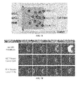
- FIG. 16 is a photomicrograph showing a 2D perfusion culture of MCF-10A cells after 7 days. The left side shows cells in relation to the open well. Right shows a magnified view of cells in the culture chamber, demonstrating a confluent monolayer of cells on the bottom surface.
- FIG. 17 is a photomicrograph showing a 3D perfusion culture of MCF-10A cells after 7 days.
- Cells were embedded in BD Matrigel. Left shows cells in relation to the open well. Right shows a magnified view of cells in the culture chamber, demonstrating a clustered 3D aggregate morphology suspended in gel.
- FIG. 18 is a photograph of an open chamber with cells. (Top) and a close up of the channel structure, showing the open cell chamber, perfusion barrier ring, flow channel, and outer air channel (Bottom) according to specific embodiments of the invention.
- FIG. 19A-B are photographs illustrating an example of an active control plate according to specific embodiments.
- FIG. 20A-B are schematics illustrating an example of an active control plate according to specific embodiments.
- FIG. 21A-B are schematics and a photo illustrating an example of (A) a cross section of the open chamber showing materials used for construction.
- the bottom layer is a solid glass slide.
- On top is a layer of molded PDMS containing microfluidic structures as described herein.
- an acrylic sheet is used in the molding process and the PDMS remains attached to it.
- this acrylic sheet is laser cut, etched, drilled or otherwise opened to create the open top culture chamber.
- a ring of Teflon tape or similar hydrophobic material is placed around the open chamber inside the well to increase the surface tension, for example by preventing wetting of the acrylic.
- the acrylic may be coated or treated or fabricated to have a higher hydrophobicity.
- the open chamber is laser cut in these three layers (prior to attaching the glass bottom) and (B) a photograph showing the Teflon ring on the top surface of the device. Clear liquid is filled in the open chamber, with microchannels filled with red dye.
- FIG. 22A-C shows a top view, side view, and plan view of a schematic of an example manifold according to specific embodiments of the invention.
- the eight tubing lines to the right are for compressed air, and each is configured to provide pressure to a column of cell inlet wells in a microfluidic array.
- the left-most line in the figure is for vacuum and connects to an outer vacuum ring around the manifold.
- Each column of wells is generally connected to a single pressure line with wells above imaging regions skipped.
- FIG. 23 illustrates an example system and manifold for operating the microfluidic plates according to specific embodiments of the invention.
- FIG. 24 illustrates a manifold with additional gas line and an objective lens according to specific embodiments of the invention.
- FIG. 25 is a graph illustrating an example of flow rate difference between a surface tension mechanism and a gravity driven mechanism according to specific embodiments of the invention.
- FIG. 26 is a graph illustrating an example of the extent to which gravity perfusion rate is responsive to the liquid level difference between the two upper reservoir wells according to specific embodiments of the invention.
- FIG. 27 illustrates a top view schematic of an example cell culture automation system according to specific embodiments of the invention.
- FIG. 28 is a photograph of an example automated microfluidic perfusion array system according to specific embodiments of the invention.
- FIG. 29 illustrates operation steps of a less automated or prototype system according to specific embodiments of the invention.
- FIG. 30 is a block diagram showing a representative example logic device in which various aspects of the present invention may be embodied.
- FIG. 31 (Table 1) illustrates an example of diseases, conditions, or states that can evaluated or for which drugs or other therapies can be tested according to specific embodiments of the present invention.
- a “particle” refers to biological cells, such as mammalian or bacterial cells, viral particles, or liposomal or other particles that may be subject to assay in accordance with the invention. Such particles have minimum dimensions between about 50-100 nm, and may be as large as 20 microns or more. When used to describe a cell assay in accordance with the invention, the terms “particles” and “cells” may be used interchangeably.
- a “microchannel” or “channel” or “flow channel” generally refers to a micron-scale channel used for fluidically connecting various components of systems and devices according to specific embodiments of the invention.
- a microchannel typically has a rectangular, e.g., square, or rounded cross-section, with side and depth dimensions in a preferred embodiment of between 10 and 500 microns, and 10 and 500 microns, respectively. Fluids flowing in the microchannels may exhibit microfluidic behavior.
- the term “microchannel” and “channel” are used interchangeably.
- Flow channel generally denotes channels designed for passage of media, reagents, or other fluids or gels and in some embodiments cells.
- “Culture channel” or “cell culture channel” generally denotes a portion of a cell culture structure that cells are designed to flow through and also remain during cell culture (though the cells may be localized into a particular culture area of the culture channel in some embodiments).
- “Air channel” generally denotes a roughly micron-scale channel used for allowing gases, such as air, oxygen enriched mixtures, etc., to pass in proximity to flow channels or culture areas.
- “Perfusion channel” is sometimes used to indicate a flow channel and any perfusion passages or structures that allow media to perfuse to the culture area.
- a “perfusion barrier” refers to a combination of solid structures and perfusion passages that generally separate a flow channel from a cell culture area or chamber.
- the perfusion passages are generally smaller than the microchannel height and/or width (for example, on the order of 5-50% or on the order of about 10%) and are designed to keep cells, other culture items, and in some embodiments gels, from migrating into the flow channels, while allowing some fluidic flow that is generally of a much higher fluidic resistance than the fluid flow in the flow channels.
- the perfusion barrier has a perfusion passage that is 4 microns high and that otherwise runs most of the length of the microchannel.
- a perfusion barrier has many perfusion passages that are about as high as the microfluidic channel, but about 4 microns wide.
- a perfusion barrier may also be referred to as an “epithelial barrier.”
- microfluidics device refers to a device having various station or wells connected by micron-scale microchannels in which fluids will exhibit microfluidic behavior in their flow through the channels.
- a “microwell array” refers to an array of two or more microwells formed on a substrate.
- a “device” is a term widely used in the art and encompasses a broad range of meaning.
- “device” may signify simply a substrate with features such as channels, chambers and ports.
- the “device” may further comprise a substrate enclosing said features, or other layers having microfluidic features that operate in concert or independently.
- the “device” may comprise a fully functional substrate mated with an object that facilitates interaction between the external world and the microfluidic features of the substrate.
- an object may variously be termed a holder, enclosure, housing, or similar term, as discussed below.
- the term “device” refers to any of these embodiments or levels of elaboration that the context may indicate.
- Microfluidic systems provide a powerful tool to conduct biological experiments. Recently, elastomer-based microfluidics has especially gained popularity because of its optical transparency, gas permeability and simple fabrication methods. However, the interface with the end-users requires labor-intensive hole punching through the elastomer, and additional steps of tubing and syringe pump connection.
- the present invention involves integrated microfluidics used for various culture and assay applications.
- the invention further involves methods of manufacture of microfluidics and components and a system for automating cell culture using such plates.
- Advantages of specific embodiments include use of a standard microtiter plate format, tubing free cell culture, and a biomimetic liver microenvironment.
- a system according to specific embodiments of the invention can be operated using standard techniques and equipment for handling standard microtiter plates, as are well known in the art.
- liquid dispensing is achieved with standard pipette mechanics, and cell culture and analysis can be made compatible with existing incubators and plate readers.
- a novel cell loading system uses a pneumatic manifold and pneumatic pressure to place cells in the micro culture area.
- microfluidic cell culture and analysis can be fully automated using other automated equipment that exists for handling standard titer plates.
- the gravity driven flow culture configuration utilizes the medium level difference between the inlet and outlet well as well as engineering the fluidic resistances to achieve the desirable flow rate in nL/min regime. This provides the significant advantage of being able to “passively” flow culture medium for long periods of time (up to 4 days) without the use of bulky external pumps or tubes.
- the invention involves a microfluidic system to allow control of the cell culture environment for long-term time-lapse microscopy of adherent cells.
- a microfluidic system to allow control of the cell culture environment for long-term time-lapse microscopy of adherent cells.
- system biology As the trend towards “systems biology” continues, it will become increasingly important to study dynamic behavior in individual live cells as well as to improve the functionality and economics of high throughput live cell screening.
- the invention provides a multiplexed microfluidic flow chamber allowing for time-lapse microscopy experimentation among other assays.
- the microfluidic chamber uses an artificial endothelial barrier to separate cells from flow channels.
- the device is formatted to a standard well plate, allowing liquid and cell samples to be directly pipetted into the appropriate inlet reservoirs using standard equipment.
- a custom pneumatic flow controller is then used to load the cells into the culture regions as well as to switch between different exposure solutions.
- a digital software interface can be used to allow a user to program specific inputs (pulses, ramps, etc.) over time to expose the cells to complex functions during time-lapse imaging.
- Dynamic responses in living cells are the foundation for phenomena such as biological signal processing, gene expression regulation, differentiation, and cell division.
- the invention involves a system capable of controlling the cellular micro-environment in a multiplexed format compatible with current cell culture methods.
- Cell response can be quantified using high magnification fluorescence microscopy to derive kinetic information with sub-cellular resolution. This capability has broad applications in cellular systems biology where dynamic single cell response experiments are not currently practical.
- one or more micro culture areas are connected to a medium or reagent channel via a grid of fluidic passages (or diffusion inlets or conduits), wherein the grid comprises a plurality of intersecting high fluidic resistance perfusion passages.
- passages in the grid are about 1 to 4 ⁇ m in height, 25 to 50 ⁇ m in length and 5 to 10 ⁇ m in width, the grid allowing for more even diffusion between medium or reagent channels and the culture area and allowing for easier manufacturing and more even diffusion.
- the high fluidic resistance ratio between the microchamber and the perfusion/diffusion passages or grid offers many advantages for cell culture such as: (1) size exclusion of cells; (2) localization of cells inside a microchamber; (3) promoting a uniform fluidic environment for cell growth; (4) ability to configure arrays of microchambers or culture areas; (4) ease of fabrication, and (5) manipulation of reagents without an extensive valve network. Examples were illustrated wherein a grid-like perfusion barrier can be much shorter than the culture area or can be near to or at the same height, according to specific embodiments of the invention and further wherein various configurations for culture devices were illustrated.
- the application also discussed a CAD drawing of a proposed 96-unit microfluidic bioreactor wherein each well was an SBS standard size (3.5 mm in diameter) in order to be compatible with existing robotic liquid handling systems and plate readers.
- the application also discussed several different configurations for an artificial sinusoid using both cut passages and grids and with a flow-around perfusion design.
- FIG. 1 is a top view of an example array of cell culture units provided on a 96-well standard SBS plate according to specific embodiments of the invention.
- 32 culture units are provided on a 96-well plate (such as the Society for Biomolecular Screening (SBS) standard microfluidic bioreactor array schematic), with wells arranged in 12 columns (shown vertically and labeled as is standard in the art, 1-12 from top to bottom) by 8 rows (shown horizontally and labeled as is standard in the art, A-H from left to right).
- SBS Society for Biomolecular Screening
- each cell culture unit occupies three wells, one for use as a medium inlet, one for use as a cell inlet/medium outlet, and one for use for cell imaging (which appears as a dark rectangle in the wells in the figure) and/or for providing air passages to a cell culture area.
- each unit can be used as an independent biomimetic cell.
- FIG. 2 through FIG. 3 show further details of structures according to specific embodiments of the invention. For purposes of clarity, each of these figures can be understood as further detail of the example configuration discussed above.
- FIG. 2 is an underside view showing one culture unit occupying three wells in an example array according to specific embodiments of the invention.
- the cell culture portion visible in the middle well is divided into four blocks, with each block having four separated cell culture areas (or channels) surrounded by medium channels used for medium fluidic passage.
- these four separated cell culture areas may be referred to as sinusoids or artificial sinusoids, regardless of whether the far end of the areas has a rounded shape. Separation into four blocks facilitates air diffusion through the material that defines the microfluidic channels (such as silicone elastomer polydime-thylsiloxane (PDMS)) structure into the culture areas.
- PDMS silicone elastomer polydime-thylsiloxane
- FIG. 3 illustrates high aspect ratio channels (also referred to herein as perfusion passages or perfusion barriers) surrounding cell culture areas in an example array according to specific embodiments wherein channels between solid structures are approximately 4 ⁇ m wide and 40 ⁇ m tall to prevent cells from growing out.
- the channels in this example are separated by approximately 40 ⁇ m solid structures.
- FIG. 4A-B are simplified schematic diagrams illustrating in three dimensions the components of a multi well (e.g., 3) microfluidic system including a representation of the well frame according to specific embodiments of the invention.
- a multi well e.g., 3
- FIG. 4A-B are simplified schematic diagrams illustrating in three dimensions the components of a multi well (e.g., 3) microfluidic system including a representation of the well frame according to specific embodiments of the invention.
- FIG. 5 is a simplified side view showing a structure according to specific embodiments of the invention illustrating two wells that are used in cell flow and fluid flow. Both views show side views of the device and illustrate glass layer 501 , microfluidics layer 502 , well layer 503 , lower reservoir 504 , and upper reservoir 505 .
- the present invention can be used in a variety of cell culture systems, including novel improved microfluidic systems, methods, designs, devices, and/or configurations as discussed in above referenced applications and incorporated herein by reference.
- three wells are used for each otherwise independent cell culture system.
- artificial sinusoids with artificial epithelial barriers are provided with just one (optionally shared or multiplexed) fluidic inlet and one (optionally shared or multiplexed) fluidic output, where the medium output also functions as a cellular input.
- artificial sinusoids with artificial epithelial barriers with just one fluidic inlet and one fluidic output are divided into blocks with air channels provided between blocks.
- air holes are provided in the well chamber above the cell culture area of a microfluidic cellular culture array, where the medium output also functions as a cellular input.
- a multiplexed medium inlet structure and multiplexed cellular input structure are provided to connect inputs and outputs to blocks of artificial sinusoids.
- a multiplexed medium inlet structure and larger shared cellular input structure are provided to connect inputs and outputs to blocks of artificial sinusoids.
- artificial sinusoids are configured with non-open portions of an epithelial barrier to better localize cells, and with perfusions inlets surrounding a cell culture area and optionally also present near a cell inlet area of the sinusoid.
- longer artificial sinusoid chambers are provided.
- the cell culture area as described above.
- Various configurations are possible for the epithelial barrier (or perfusion barrier), such as a grid-like passage structure.
- Other variations will be suggested to those of skill in the art having the teachings provided herein.
- the structures disclosed above can also be adapted to systems using more or fewer wells on a standard microtiter well plate or a fully customized or partially customized plate, such as those described in referenced documents and in other examples herein.
- Plates and systems as described herein can be used with other configurations of cell culture areas or cell culture chambers and micro-fluidic flow structures, including one or more of the novel designs described below.
- FIG. 6A-C illustrate configuration and operation of an example roughly rectangular cell culture chamber design according to specific embodiments of the invention.
- the cell culture area provided is an essentially rectangular cell culture chamber.
- the cell culture chamber has cell inlet and outlet passages E 2 shown at the right, and flow outlets E 1 also shown at the right.
- the cell passages are paired, with the center pair used for cell flow loading and the pairs on either side used as a cell flow outlet.
- Multiple separate flow inlets are shown on the left, labeled A 1 , A 2 , B 1 , B 2 , C 1 , C 2 and in this example design the flow inlets have a grid pattern to prevent blockage by cells.
- Air diffusion channels are shown surrounding the chamber.
- Outlet E 1 provides an outlet for fluid flow that is partially isolated from the culture chamber.
- FIG. 6B illustrates cell loading in a culture unit as shown in FIG. 6A .
- Cells are loaded via a low resistance fluidic path (with higher resistance in the flow paths).
- the cells are prevented from blocking the flow paths by the resistance ratio (the cells preferentially flow to the cell outlet instead of the flow channels).
- the channels in this particular embodiment are arranged such that the cell in and cell out channels are on the right side of the chamber. This results in the unique feature where flow of cells goes into the chamber, makes a 180 degree turn, and flows out, as illustrated by the sharply curved streamlines shown in FIG. 6B from the Cell In to Cell Out passages.).
- cells are loaded (via capillary force) from the center right channel(s) and out from the top and bottom right channels.
- a very small amount of flow is directed towards the side outlet channels (the longer less curved streamlines shown in FIG. 6B exiting at the left edge of the chamber).
- the side flow is not important for cell loading, but serves to help distribute cells more evenly in the chamber. Because of the low velocity of the flow, the cells naturally settle onto the chamber floor without needing any physical barrier.
- the cell outlet paths help make the loading symmetric, as well as to increase the number of cells loaded into the chamber. This loading mechanism can be used to load cells, particles, beads, gels, gels with cells, etc.
- FIG. 6C is a photomicrograph showing cells loaded into a microfluidic chamber as described above.
- FIG. 7A-E illustrate configuration and operation of a second example roughly rectangular new cell culture chamber design according to specific embodiments of the invention. This example design differs only slightly from that of FIG. 6 and all operation modes described for one of these two designs herein apply to the other.
- FIG. 7A illustrates cell loading in a culture unit with an essentially rectangular cell culture chamber using with cell inlet and outlet passages shown at the right and flow outlets also shown at the right.
- the cell passages are unpaired.
- Three unpaired flow inlets are shown on the left and these also have a grid pattern to prevent blockage by cells.
- Air diffusion channels generally are placed near the chamber, though not shown in this figure.
- FIG. 7B is a photomicrograph showing three different cell types loaded at four different concentrations of cells loaded into a microfluidic chamber as described above.
- FIG. 7C is a photomicrograph showing a close-up view of mouse embryonic stem cells cultured in the microfluidic device as described above.
- FIG. 7D is a photomicrograph showing cell growth in the microfluidic device as described above.
- FIG. 7E illustrates creating a gradient in the culture chamber by flowing 2 (or more) solutions at once according to specific embodiments of the invention in the microfluidic device as described above.
- FIG. 8A-C illustrate configuration and operation of an example cell culture chamber design for 3D gel cell culture according to specific embodiments of the invention.
- This example includes a cell/gel perfusion barrier with a cross-hatch perfusion passage design.
- the cross hatch design allows cells in a gel matrix to be flowed into the chamber and allows for perfusion of media. While the cross-hatch perfusion barrier is presently preferred in some designs, culture chambers with different perfusion barriers or no perfusion barriers are also implemented according to specific embodiments.
- a flow around channel for media includes an outlet and inlet both on the same side of the barrier.
- FIG. 8A illustrates a general embodiment where the outlet and inlet openings are shown to the right.
- a cell culture chamber is modified to allow easier culture of cells in 3D gel matrix.
- a perfusion barrier separates the cell culture area and the flow channel as illustrated.
- the barrier is designed to retain a 3D gel in the culture chamber. Coupling the barrier with the 3-channel cell/gel inlet design described above is an important feature that provides improved performance. By having separate flow inlets/outlets on each side of the barrier, it is possible to localize a fluid gel in the culture chamber, and not have it obstruct the flow channel.
- the invention creates a 3D gel environment for biologic cell culture, for example using a temperature sensitive gel culture matrix, such as MatrigelTM, GeltrexTM, collagen, etc.
- An example gel is liquid at 4 C, which, for example polymerizes at room temperature or 37 C.
- cells are initially mixed with a cell suspension on ice. The solution is then pipetted into the cell inlet well, and carried into the microfluidic chamber via capillary flow. In specific examples, the plate is kept at room temperature. The flow rate allows sufficient cell/gel solution to fully fill the culture chamber prior to polymerization. The barrier prevents any of the gel solution from leaking into the flow channel. As the gel warms up, it polymerizes into a solid mass, with cells embedded.
- a temperature sensitive gel culture matrix such as MatrigelTM, GeltrexTM, collagen, etc.
- An example gel is liquid at 4 C, which, for example polymerizes at room temperature or 37 C.
- cells are initially mixed with a cell suspension on ice. The solution is then
- FIG. 8C illustrates cell/gel loading that operates generally as described above.
- FIG. 8D illustrates a cell/gel culture with a medium exposed through a perfusion according to specific embodiments of the invention.
- FIG. 8E illustrates two micrographs showing a culture chamber with an air channel, flow channel, barrier, and cell region according to specific embodiments of the invention. In the right portion, the same region is shown, with a fluorescently labeled gel. Note the gel fully occupies the cell culture chamber but does not extend beyond the barrier.
- FIG. 9 is a schematic diagram showing steps from an empty culture region to performing a cell assay according to specific embodiments of the invention.
- Various novel aspects according to specific embodiments of the invention simplify these steps and allow them to be automated.
- Cell loading in specific embodiments of the invention can utilize the rapid surface tension flow between the cell inlet and the flow inlet.
- the cell inlet reservoir (upper and lower) is aspirated of its priming solution.
- the flow inlet upper reservoir is aspirated.
- An amount (e.g., five microliters) of cell suspension e.g., trypsinized HeLa human cancer cell line, 5 ⁇ 10 5 cells/ml
- the flow inlet lower reservoir is aspirated, causing liquid to flow from cell inlet to flow inlet via surface tension/capillary force.
- Cell loading in various configurations can be completed in approximately 2-5 minutes.
- the cell loading reservoir is then washed with medium (e.g., Dulbecco's Modified Eagle's Medium, DMEM) and filled with e.g., 50-100 microliters of clean medium.
- medium e.g., Dulbecco's Modified Eagle's Medium, DMEM
- the plate is was placed in a controlled culture environment for a period (e.g., 37 C, 5% CO 2 incubator for 2-4 hours) to allow for cell attachment.
- a controlled culture environment e.g., 37 C, 5% CO 2 incubator for 2-4 hours
- multiplexed perfusion imaging of cells can be performed in a 3D gel matrix.
- An example plate contains 24 independent culture units that can be loaded with cells/gel as a user chooses.
- each row of the plate contains 3 fully independent flow units (4 wells each), consisting of a medium inlet (e.g., cols. 1, 5, 9), a cell culture/imaging well (e.g., cols. 2, 6, 10), cell/gel inlet (cols. 3, 7, 10), and an outlet (cols 4, 8, 12).
- Air diffusion channels blue
- the inlets are designed to allow continuous flow of culture media to the cells at 40 ⁇ l/day via a gravity driven process.
- each chamber is 1.5 ⁇ 0.5 mm in size, with a height of 200 ⁇ m.
- the perfusion bather green ensures uniform nutrient transfer through the gel matrix and a thin cover glass bottom (170 ⁇ m) allows for optimum image quality.
- a cells embedded method using a medium such as BD Matrigel
- the procedure is as follows: (1) Prepare a cell suspension of 1-5 ⁇ 106 cells/ml, depending on the desired cell number for culture. Optionally, for improved results, resuspend in culture medium on ice. (2) Mix cell suspension with Matrigel on ice. A 1:1 ratio is recommended, but various dilutions are suitable depending on desired gel density. Keep on ice until loaded into the microfluidic plate. (3) Aspirate the flow inlet, cell/gel inlet, and flow outlet wells. Generally, it is desired to empty the liquid from the holes at the bottom of the wells.
- the flow channel passes next to the cell culture chamber, and feeds the cells via diffusion as described above.
- the minimum barrier dimension is 2 micron, allowing soluble factors to freely pass through. Diffusion across the culture chamber occurs in ⁇ 20 minutes. (7) For long term culture, refill the flow inlet and empty the flow outlet at an appropriate interval, e.g., every 3 days.
- a cell suspension may be loaded into the plate without gel and the gel can be overlaid immediately, after cell adhesion, or following a few days of growth.
- Overlay gel is placed following steps 3 and 4 above using a gel solution (with no cells). The gel will flow over the cells and polymerize in the chamber.
- any of the various novel microfluidic cell culture chambers and associated microfluidic structures can, according to specific embodiments of the invention, be integrated with a well titer plate device as is commonly used in macro cell culturing assays.
- a well titer plate device as is commonly used in macro cell culturing assays.
- a number of specific examples are provided below, though the invention encompasses other systems for integrating with the microfluidic devices.
- FIG. 10 illustrates a layout of another type of cell culture array designed for general cell culture automation according to specific embodiments of the invention.
- each culture unit consists of 4 well positions.
- the first well is for perfusion medium
- the second well is for cell inlet
- the third well is for imaging the microfluidic chamber
- the fourth well is the outlet.
- a cell barrier/perfusion channel localizes cells to the cell area and improves nutrient transport during continuous perfusion culture.
- the low fluidic resistance of the cell inlet to outlet path enables cells to be rapidly loaded via gravity or surface tension methods without an external cell loading mechanism.
- the high fluidic resistance of the perfusion inlet flow channels allows long term continuous perfusion of medium via gravity flow without any external pump mechanism.
- FIG. 11A-D illustrate a 24 unit “3D culture” plate on a 96 well plate according to specific embodiments of the invention.
- this configuration is a designed for high-thru-put production work.
- the design allows cells to be cultured in various 3D gel matrix media with continuous perfusion medium exposure for long term cell assay and cell imaging experiments.
- using a standard 96-well format and passive gravity driven perfusion allows simple integration with existing laboratory equipment.
- a 96-well plate contains 24 independent 3D culture units with microfluidic channels (which are stained in the Figure for visibility) A single unit with flow channels stained is shown in FIG. 11C .
- media flows from the inlet well past the cultured cells and collects in the outlet well.
- Cells and gel are loaded by the user into the biomimetic cell culture chamber.
- the cell chamber is designed to mimic the interstitial tissue environment, with cells embedded or overlayed in physiologic extracellular matrix (ECM), and fed via diffusion from a continuously perfused capillary channel.
- ECM extracellular matrix
- the cell microenvironment enables long term growth in, e.g., a 200 micron thick gel layer. Oxygenation channels maintain adequate gas transport, and the glass coverslide bottom allows high quality cell imaging.
- the standard layout allows the advanced microfluidic units to be operated just like a typical 96-well plate.
- the gravity driven perfusion design eliminates the need for pump or tubing connections, as described above.
- an expected number of cells per unit is about 500 cells.
- An example perfusion rate is 40 ul/day for a single unit.
- the cell chamber volume is 150 nL, and the chamber dimensions are 1.5 ⁇ 0.5 ⁇ 0.2 mm.
- the gas diffusion membrane is 50 um silicone with a bottom surface #1.5 thickness coverglass.
- cells In many microfluidic systems, cells generally must be introduced to the culture chamber via flow from a cell inlet well. This can hamper use of such devices for cultures that need to introduce large cells, cell clusters, or tissue samples that do not transport well in microchannels. In a typical existing open top well (e.g. 384 or 1586 well plate), cell seeding is easy, but there is no way to maintain a continuous flow environment to the cells.
- open top well e.g. 384 or 1586 well plate
- An open top microfluidic cell culture chamber for continuous perfusion uses the surface tension of liquid in the open chamber to counteract flow pressure, thereby preventing liquid from spilling out of the open chamber and instead flowing to downstream channels.
- embodiments allow the combination of cell introduction into an open well and integrated microfluidic perfusion control.
- FIG. 12 An important aspect of the operation of open top systems according to specific embodiments of the invention is illustrated in FIG. 12 .
- Fluid mechanics dictates that liquid will move from regions of high pressure to lower pressure. Pressure differences can be caused by gravity (difference in liquid level), applied pressure (from pumps), or surface tension.
- an open top cell culture chamber is provided such that the surface tension pressure of the liquid above the open well is higher than the chamber pressure, creating a surface tension barrier that prevents liquid from flowing up out of the open chamber.
- the angle of the fluid surface above the chamber walls is exaggerated for illustration purposes.
- P in , P st , P f , P out are the pressures at the inlet well (P in ), above the open chamber (P st ), inside the culture chamber (P f ), and at the outlet well (P out ).
- R in , R out are the fluidic resistances between the inlet well and chamber, and between the chamber and outlet well.
- FIG. 13 is an illustration of an example 96 well plate having 32 perfusion units with a dye in the culture medium for illustrative purposes according to specific embodiments of the invention
- FIG. 13B shows a top view of a single perfusion unit in an example system. The left well is the inlet, the center is the open culture chamber, and the right well is the outlet. A 2 mm open top 310 of the culture chamber is indicated by the dashed circle.
- FIG. 13C Illustrates a bottom view of a single example perfusion unit.
- the serpentine channels shown at the right control the gravity perfusion rate to be, in one example, approximately 100 microliters/day.
- FIG. 14 is a top view schematic illustration of an example design of an open top perfusion chamber according to specific embodiments of the invention.
- a 2 mm hole (white) is cut into 3 mm microfluidic chamber (orange).
- a narrow perfusion barrier (green) surrounds the culture chamber to separate flows from cells.
- An outer air channel (blue) oxygenates the medium in the flow channels (gray).
- FIG. 15 is a top view schematic illustration of an example perfusion unit according to the invention and a cross section side view schematic of an example design of an open top perfusion chamber showing representative layers.
- An example open chamber is about 2 mm in diameter with a 1 mm height.
- FIG. 15 illustrates glass layer 1501 , microfluidics layer 1502 , well layer 1503 , cell culture reservoir 1504 , microfluidic channels 1505 , teflon ring 310 , and air channel 1506 .
- This chamber design supports culture of cells in 2D systems using liquid culture medium, as well as 3D cultures as described herein.
- 2D culture cells adhere to the glass floor after being dispensed directly into the culture region. Perfusion of medium passes over the cells for long term growth.
- 3D format cells are embedded in a gel (such as BD Matrigel), and dispensed into the culture well. The gel will be localized to the central chamber by the perfusion barrier, allowing medium to flow around the gel and diffuse in to feed the cells.
- FIG. 16 is a photomicrograph showing a 2D perfusion culture of MCF-10A cells after 7 days. The left side shows cells in relation to the open well.
- FIG. 17 is a photomicrograph showing a 3D perfusion culture of MCF-10A cells after 7 days. Cells were embedded in BD Matrigel. Left shows cells in relation to the open well. Right shows a magnified view of cells in the culture chamber, demonstrating a clustered 3D aggregate morphology suspended in gel.
- a second implementation of the open top design is in an active control plate.
- the open culture chamber is routed to 6 upstream inlet wells, a gravity perfusion well, and an outlet well.
- the plate can be sealed to a pneumatic manifold, allowing pressure driven control of the 6 inlet solutions. This allows experiments where solutions are quickly changed over the cells. Pressure driven flow of up to 10 PSI is possible due to the large resistance region between the inlet and culture chamber, leading to a pressure near the chamber less than 1/1000 th the input pressure.
- FIG. 18 is a photograph of an open chamber with cells. (Top) and a close up of the channel structure, showing the open cell chamber, perfusion barrier ring, flow channel, and outer air channel (Bottom) according to specific embodiments of the invention.
- FIG. 19A-B are photographs illustrating an example of an active control plate according to specific embodiments.
- FIG. 19A shows a plate design with 4 independent flow units (rows of the plate) with 6 inlet solutions, an open chamber, an outlet, and a gravity flow channel.
- FIG. 19B shows the four open chambers (green circles), with inlet streams above and outlet streams below the open chamber.
- the design allows flows to pass from the inlet to outlet channels without overflowing the open chamber.
- the availability of multiple liquid or reagent inlets provides systems that are particularly good for live cell imaging and other experiments and assays in cell biology. In such a system a research can study cultures of pancreatic or other organ cells, or cancer cells, to determine how they respond to different drugs or other stimulus introduced via the inlets.
- a gravity well is also provides to facilitate maintaining (e.g., feeding) the cells before experiments are performed.
- FIG. 20A illustrates the layout of the active control plate with 4 independent units (rows), 6 upstream inlets (A 1 -A 6 , B 1 -B 6 , C 1 -C 6 , D 1 -D 6 ), the open chambers (red circles) in a central imaging window with four culture chambers, a large outlet well (oval, A 7 , B 7 , C 7 , D 7 ), and gravity perfusion well (last column, A 8 , B 8 , C 8 , D 8 ).
- FIG. 20AB is a schematic of the culture chamber showing the 6 inlet channels, 2 mm diameter open culture chamber (red), outlet (center right), and gravity feed (top and bottom right).
- FIG. 21A-B are schematics and a photo illustrating an example of (A) a cross section of the open chamber showing materials used for construction.
- the bottom layer is a solid glass slide.
- On top is a layer of molded PDMS containing microfluidic structures as described herein.
- an acrylic sheet is used in the molding process and the PDMS remains attached to it.
- this acrylic sheet is laser cut, etched, drilled or otherwise opened to create the open top culture chamber.
- a ring of Teflon tape or similar hydrophobic material is placed around the open chamber inside the well to increase the surface tension, for example by preventing wetting of the acrylic.
- the acrylic may be coated or treated or fabricated to have a higher hydrophobicity.
- the open chamber is laser cut in these three layers (prior to attaching the glass bottom) and (B) a photograph showing the Teflon ring on the top surface of the device. Clear liquid is filled in the open chamber, with microchannels filled with red dye.
- the Teflon ring for example, increases the hydrophobicity of the top surface. This increases the surface tension and prevents liquid from spilling out of the culture chamber.
- the Teflon is applied during fabrication of the bottom acrylic portion of the plate. A strip of Teflon is taped onto the acrylic sheet before laser cutting.
- the laser cutter creates the open chamber by cutting through the PDMS, acrylic, and Teflon at the same time.
- the laser cutter also preferably cuts the excess Teflon tape around the outside of the cell chamber opening to create the circular ring.
- the end result is a Teflon ring that is a roughly donut shape with 1 mm width and 200 micron thickness. Cutting off the excess Teflon or otherwise restricting the hydrophobic treatment of the acrylic to the area just around the culture chamber can facilitate subsequent joining of the acrylic bottom to an open bottom well plate. Since cell culture media is hydrophilic, a surface that is hydrophilic will prevent the liquid from flowing out of the well. Telfon is an extremely hydrophobic material with a water contact angle around 120 degrees. Without the Teflon, there is a liquid/air/acrylic interface, which is less hydrophobic, and more likely to overflow during experiment.
- the holes through the acrylic may be drilled so that there is a sunken edge around the culture chamber hole and that sunken edge can be treated to be hydrophobic while leaving the surface that attaches to the well portion untreated.
- a proprietary pneumatic manifold as described herein, is mated to the plate and pneumatic pressure is applied to the cell inlet area for cell loading.
- overall cell culture area design can be made more effective when it is not necessary to allow for passive cell loading.
- FIG. 22A-C shows a top view, side view, and plan view of a schematic of an example manifold according to specific embodiments of the invention.
- the eight tubing lines to the right are for compressed air, and each is configured to provide pressure to a column of cell inlet wells in a microfluidic array.
- the left-most line in the figure is for vacuum and connects to an outer vacuum ring around the manifold.
- Each column of wells is generally connected to a single pressure line with wells above imaging regions skipped.
- the manifold is placed on top of a standard well plate.
- a rubber gasket lies between the plate and manifold, with holes matching the manifold (not shown).
- the vacuum line creates a vacuum in the cavities between the wells, holding the plate and manifold together. Pressure is applied to the wells to drive liquid into the microfluidic channels (not shown). A typical pressure of 1 psi is used, therefore the vacuum strength is sufficient to maintain an air-tight seal.
- each column is connected to a single pressure line. Columns above the cell imaging regions are skipped.
- Pressurized cell loading in a system according to specific embodiments of the invention has been found to be particularly effective in preparing cultures of aggregating cells (e.g., solid tumor, liver, muscle, etc.). Pressurized cell loading also allows structures with elongated culture regions to be effectively loaded. Use of a pressurized manifold for cell loading and passive flow for perfusion operations allows the invention to utilize a fairly simple two inlet design, without the need for additional inlet wells and/or valves as used in other designs.
- a plate manifold includes an additional “gas line” that is used to bathe the cells in the microfluidic device with a specified gas environment (for example, 5% CO 2 ).
- a specified gas environment for example, 5% CO 2
- Other examples include oxygen and nitrogen control, but any gaseous mixture can be sent to the cells.
- the gas flows through the manifold into the sealed wells above the cell culture area and holes in the microfluidic device enable the gas to flow into specified microfluidic air channels, as described above.
- the gas permeable device layer allows the gas to diffuse into the culture medium prior to exposing the cells. By continuously flowing the gas through the microfluidic plate, a stable gas environment is maintained.
- This provides an optional means for controlling the gas environment to placing the microfluidic plate into an incubator.
- the manifold can be used to create a “micro-incubator” independent of the ambient air.
- FIG. 23 illustrates an example system and manifold for operating the microfluidic plates according to specific embodiments of the invention.
- the format of the microfluidic plate design allows two automation-friendly flow modalities dependent on the extent of dispensing/aspiration.
- the first is surface tension mediated flow.
- the capillary force of the fluid/air interface along with the wetted surfaces glass, silicone, acrylic
- This effect is useful for microfluidic flows as it is only evident when the reservoir diameter is small and the flow volumes are small.
- the lower reservoir wells are 1-2 mm in diameter, and with a total flow volume of approximately 3-5 microliters. Since the microfluidic channel volume is only 0.2 microliters, this mechanism is well suited for cell loading and cell exposures.
- the second mechanism is gravity driven perfusion, which is well suited for longer term flows, as this is dependent on the liquid level difference and not the reservoir dimensions. According to specific embodiments of the invention, this may be accomplished by adding more liquid into one reservoir (typically filling near the top of the upper reservoir). The fluidic resistance through the microfluidic channels will determine how long (e.g., 24 hours) to reach equilibrium between the wells and thus determine how often wells should be refilled.
- FIG. 25 shows the flow rate difference between the surface tension mechanism and the gravity driven mechanism.
- the surface tension flow in an example, 5 microliters was dispensed into the lower reservoir followed by aspiration of the opposing lower reservoir.
- a liquid level difference of 2.5 mm was used, with both wells filled into the upper reservoir portion.
- the gravity perfusion rate is also responsive to the liquid level difference between the two upper reservoir wells as illustrated in FIG. 26 . This fact allows an automated dispenser/aspirator to control and maintain a given perfusion flow rate over a 10-fold range during culture. Here, different liquid level differences were produced via dispensing volumes and measured for volumetric flow rate.
- the liquid height difference between the inlet/outlet wells across the plate can also be precisely controlled using a mechanical tilting platform.
- a mechanical tilting platform it is possible to maintain a constant flow rate over time, as well as back-and-forth flow with different forward and reverse times (i.e. blood flow).
- perfusion cell culture can be initiated by filling the flow inlet reservoir with 200-300 microliters of fresh medium (e.g., DMEM supplemented with 10% fetal bovine serum) and aspirating the cell inlet upper reservoir.
- fresh medium e.g., DMEM supplemented with 10% fetal bovine serum
- the liquid level difference between the flow inlet and cell inlet wells will then cause a continuous gravity driven flow through the attached cells.
- the flow inlet well is refilled and the cell inlet well aspirated during a period depending on fluidic resistance and reservoir volumes (e.g., every 12, 24, 36, 48, 72 hours).
- Cell assay can be performed directly on the microfluidic cell culture using standard optically based reagent kits (e.g. fluorescence, absorbance, luminescence, etc.). For example a cell viability assay utilizing conversion of a substrate to a fluorescent molecule by live cells has been demonstrated (CellTiter Blue reagent by Promega Corporation).
- CellTiter Blue reagent by Promega Corporation.
- the reagent is dispensed into the flow inlet reservoir and exposed to the cells via gravity perfusion over a period of time (e.g., 21 hours).
- the new fluid can be added to the flow inlet reservoir followed by aspiration of the cell inlet reservoir.
- Data can be collected directly on the cells/liquid in the microfluidic plate, such as placing the plate into a standard fluorescence plate reader (e.g., Biotek Instruments Synergy 2 model).
- the substrate may diffuse into the outlet medium, and therefore be easily detected in the cell inlet reservoir.
- the plate can be placed on a scanning microscope or high content system.
- an automated Olympus IX71 inverted microscope station can be used to capture viability of cultured liver cells with a 20 ⁇ objective lens.
- cells By repeatedly filling/aspirating the wells, cells can be maintained for long periods of time with minimal effort (e.g. compared to standard “bioreactors” which require extensive sterile preparation of large fluid reservoirs that cannot be easily swapped out during operation).
- FIG. 27 illustrates a top view schematic of an example cell culture automation system according to specific embodiments of the invention.
- various “off-the-shelf” machines can be used to create an automated system. This schematic shows an example of how this is accomplished.
- a robotic arm (plate handler) moves the microfluidic plates from station to station.
- An automated incubator stores the plates at the proper temperature and gas environment for long term perfusion via gravity flow.
- the pipettor dispenses liquids (media, drugs, assay reagents, etc.) to the inlet wells and removes liquid from the outlet wells.
- a plate reader is used for assay.
- the cell loader is optionally used to introduce the cells to the microfluidic arrays at the beginning of the experiment.
- the cell loader in particular is generally not “off-the-shelf” and operates by applying pneumatic pressure to specified wells of the array plate to induce flow. Standard or custom computer software is available to integrate operations.
- FIG. 28 is a photograph of an example automated microfluidic perfusion array system according to specific embodiments of the invention.
- the basic process includes: 1) removing the plate from the incubator, 2) removing liquid from the outlet wells via the pipettor, 3) moving a media/drug storage plate from the “plate stacks,” 4) transferring liquid from the media/drug plate to the microfluidic plate via the pipettor, 5) placing the microfluidic plate into the incubator, 6) repeat for each plate, 7) repeat after specified time interval (e.g. 24 hours).
- FIG. 29 illustrates operation steps of a less automated or prototype system according to specific embodiments of the invention.
- the 96-well plate standard allows the microfluidic system to be operated using standard techniques and equipment. For example, liquid dispensing is achieved with standard pipette mechanics, and cell culture and analysis is compatible with existing incubators and plate readers.
- a custom built cell loading system can be used to load the cells using air pressure as described above.
- the gravity driven flow culture configuration utilizes the medium level difference between the inlet and outlet well as well as engineering the fluidic resistances to achieve the desirable flow rate in nL/min regime. This provides the significant advantage of being able to “passively” flow culture medium for long periods of time (for example, up to 4 days) without the use of bulky external pumps.
- Integrated systems for the collection and analysis of cellular and other data as well as for the compilation, storage and access of the databases of the invention typically include a digital computer with software including an instruction set for sequence searching and/or analysis, and, optionally, one or more of high-throughput sample control software, image analysis software, collected data interpretation software, a robotic control armature for transferring solutions from a source to a destination (such as a detection device) operably linked to the digital computer, an input device (e.g., a computer keyboard) for entering subject data to the digital computer, or to control analysis operations or high throughput sample transfer by the robotic control armature.
- the integrated system further comprises valves, concentration gradients, fluidic multiplexors and/or other microfluidic structures for interfacing to a microchamber as described.
- the present invention can comprise a set of logic instructions (either software, or hardware encoded instructions) for performing one or more of the methods as taught herein.
- software for providing the data and/or statistical analysis can be constructed by one of skill using a standard programming language such as Visual Basic, Fortran, Basic, Java, or the like.
- a standard programming language such as Visual Basic, Fortran, Basic, Java, or the like.
- Such software can also be constructed utilizing a variety of statistical programming languages, toolkits, or libraries.
- FIG. 30 shows an information appliance (or digital device) 700 that may be understood as a logical apparatus that can read instructions from media 717 and/or network port 719 , which can optionally be connected to server 720 having fixed media 722 .
- Apparatus 700 can thereafter use those instructions to direct server or client logic, as understood in the art, to embody aspects of the invention.
- One type of logical apparatus that may embody the invention is a computer system as illustrated in 700 , containing CPU 707 , optional input devices 709 and 711 , disk drives 715 and optional monitor 705 .
- Fixed media 717 , or fixed media 722 over port 719 may be used to program such a system and may represent a disk-type optical or magnetic media, magnetic tape, solid state dynamic or static memory, etc.
- the invention may be embodied in whole or in part as software recorded on this fixed media.
- Communication port 719 may also be used to initially receive instructions that are used to program such a system and may represent any type of communication connection.
Abstract
Description
- 1. T. H. Park and M. L. Shuler, Biotechnol. Prog., 2003, 19, 243.
- 2. G. M. Walker, H. C. Zeringue and D. J. Beebe, Lab Chip, 2004, 4, 91.
- 3. E. Leclerc, Y. Sakai and T. Fujii, Biotechnol. Prog., 2004, 20, 750.
- 4. M. J. Powers, K. Domansky, M. R. Kaazempur-Mofrad, A. Kalezi, A. Capitano, A. Upadhyaya, P. Kurzawski, K. E. Wack, D. B. Stolz, R. Kamm and L. G. Griffith, Biotechnol. Bioeng., 2002, 78, 257.
- 5. K. Viravaidya and M. L. Shuler, Biotechnol. Prog., 2004, 20, 590.
- 6. Y. Kostov, P. Harms, L. Randers-Eichhorn and G. Rao, Biotechnol. Bioeng., 2001, 72, 346.
- 7. N. Li Jeon, H. Baskaran, S. K. Dertinger, G. M. Whitesides, L. Van der Water and M. Toner, Nat. Biotechnol., 2002, 20, 826.
- 8. T. Thorsen, S. J. Maerkl and S. R. Quake, Science, 2002, 298, 580.
- 9. H. Andersson and A. van den Berg, Lab Chip, 2004, 4, 98.
Other References II - 10. Dove, A. (2003) Nature Biotechnology 21, 859-864.
- 11. Entzeroth, M. (2003) Current Opinion in
Pharmacology 3, 522-529. - 12. Boess, F.; Kamber, M.; Romer, S.; Gasser, R.; Muller, D.; Albertini, S.; Suter, L. Toxicol Sci 2003, 73, (2), 386-402.
- 13. Rodriguez-Antona, C.; Donato, M. T.; Boobis, A.; Edwards, R. J.; Watts, P. S.; Castell, J. V.; Gomez-Lechon, M. J. Xenobiotica 2002, 32, (6), 505-20.
- 14. Cukierman, E.; Pankov, R.; Stevens, D. R.; Yamada, K. M. Science 2001, 294, (5547), 1708-12.
- 15. Griffith, L. G.; Swartz, M. A. Nat Rev
Mol Cell Biol 2006, 7, (3), 211-24. - 16. Revzin, A.; Rajagopalan, P.; Tilles, A. W.; Berthiaume, F.; Yarmush, M. L.; Toner, M. Langmuir 2004, 20, (8), 2999-3005.
- 17. Flaim, C. J.; Chien, S.; Bhatia, S. N.
Nat Methods 2005, 2, (2), 119-25. - 18. Anderson, D. G.; Levenberg, S.; Langer, R. Nat Biotechnol 2004, 22, (7), 863-6.
- 19. Battle, T.; Stacey, G. Cell Biol Toxicol 2001, 17, (4-5), 287-99.
- 20. LeCluyse, E. L.; Bullock, P. L.; Parkinson, A. Advanced Drug Delivery Reviews 1996, (22), 133-186.
- 21. Ben-Ze'ev, A.; Robinson, G. S.; Bucher, N. L.; Farmer, S. R. Proc Natl Acad Sci USA 1988, 85, (7), 2161-5.
- 22. Bhatia, S. N.; Balis, U. J.; Yarmush, M. L.; Toner, M. Faseb J 1999, 13, (14), 1883-900.
- 23. Berthiaume, F.; Moghe, P. V.; Toner, M.; Yarmush, M. L.
Faseb J 1996, 10, (13), 1471-84. - 24. Stevens, M. M.; George, J. H.
Science 2005, 310, (5751), 1135-8. - 25. Bissell, M. J.; Rizki, A.; Mian, I. S. Curr Opin Cell Biol 2003, 15, (6), 753-62.
- 26. Allen, J. W.; Bhatia, S. N. Biotechnol Bioeng 2003, 82, (3), 253-62.
- 27. Hung, P. J.; Lee, P. J.; Sabounchi, P.; Aghdam, N.; Lin, R.; Lee, L. P.
Lab Chip 2005, 5, (1), 44-8. - 28. Lee, P. J.; Hung, P. J.; Rao, V. M.; Lee, L. P. Biotechnol Bioeng 2005.
- 29. Puhl, G.; Schaser, K. D.; Vollmar, B.; Menger, M. D.; Settmacher, U. Transplantation 2003, 75, (6), 756-61.
- 30. Park, J.; Berthiaume, F.; Toner, M.; Yarmush, M. L.; Tilles, A. W.
Biotechnol Bioeng 2005, 90, (5), 632-44. - 31. Anderson, K.; Wilkinson, R.; Grant, M. H. Int J Artif Organs 1998, 21, (6), 360-4.
- 32. Landry, J.; Bernier, D.; Ouellet, C.; Goyette, R.; Marceau, N. J Cell Biol 1985, 101, (3), 914-23.
- 33. A. Ben-Ze'ev, G. S. Robinson, N. L. Bucher, S. R. Farmer, Proc Natl Acad Sci USA 85, 2161 (April, 1988).
- 34. J. Landry, D. Bernier, C. Ouellet, R. Goyette, N. Marceau, J Cell Biol 101, 914 (September, 1985).
- 35. S. A. Stoehr, H. C. Isom, Hepatology 38, 1125 (November, 2003).
- 36. Zhang, X, Wang, W, Yu, W, Xie, Y, Zhang, X, Zhang, Y, Ma, X. Biotechnol Prog 2005, 21, 1289-96.
- 37. Kelm, J, Timmins, N, Brown, C, Fussenegger, M, Nielsen, L. Biotechnology and Bioengineering. 2003, 83(2)173-180.
- 38. Kuns-Schughart, L, Freyer, J, Hofstaedter, F, Ebner, R. J. Biomolecular Screening. 2004, 9(4) 273-285.
Claims (16)
Priority Applications (5)
| Application Number | Priority Date | Filing Date | Title |
|---|---|---|---|
| US13/011,857 US9388374B2 (en) | 2005-07-07 | 2011-01-21 | Microfluidic cell culture systems |
| US13/761,130 US9353342B2 (en) | 2010-01-21 | 2013-02-06 | Cell culture and gradient migration assay methods and devices |
| US14/081,314 US9353343B2 (en) | 2010-01-21 | 2013-11-15 | Cell culture and gradient migration assay methods and devices |
| US15/161,665 US10179897B2 (en) | 2010-01-21 | 2016-05-23 | Cell culture and gradient migration assay methods and devices |
| US15/175,749 US20160333298A1 (en) | 2005-07-07 | 2016-06-07 | Microfluidic Cell Culture Systems |
Applications Claiming Priority (12)
| Application Number | Priority Date | Filing Date | Title |
|---|---|---|---|
| US69744905P | 2005-07-07 | 2005-07-07 | |
| US75639906P | 2006-01-04 | 2006-01-04 | |
| US77346706P | 2006-02-14 | 2006-02-14 | |
| US11/648,207 US8257964B2 (en) | 2006-01-04 | 2006-12-29 | Microwell cell-culture device and fabrication method |
| US90065107P | 2007-02-08 | 2007-02-08 | |
| US1888208P | 2008-01-03 | 2008-01-03 | |
| US12/019,857 US9354156B2 (en) | 2007-02-08 | 2008-01-25 | Microfluidic particle analysis method, device and system |
| US3729708P | 2008-03-17 | 2008-03-17 | |
| US12/348,907 US9376658B2 (en) | 2008-01-03 | 2009-01-05 | Cell culture array system for automated assays and methods of operation and manufacture thereof |
| US29727810P | 2010-01-21 | 2010-01-21 | |
| US36737110P | 2010-07-23 | 2010-07-23 | |
| US13/011,857 US9388374B2 (en) | 2005-07-07 | 2011-01-21 | Microfluidic cell culture systems |
Related Parent Applications (1)
| Application Number | Title | Priority Date | Filing Date |
|---|---|---|---|
| US13/436,992 Continuation-In-Part US9637715B2 (en) | 2005-07-07 | 2012-04-01 | Cell culture and invasion assay method and system |
Related Child Applications (2)
| Application Number | Title | Priority Date | Filing Date |
|---|---|---|---|
| US13/761,130 Continuation-In-Part US9353342B2 (en) | 2010-01-21 | 2013-02-06 | Cell culture and gradient migration assay methods and devices |
| US15/175,749 Continuation US20160333298A1 (en) | 2005-07-07 | 2016-06-07 | Microfluidic Cell Culture Systems |
Publications (2)
| Publication Number | Publication Date |
|---|---|
| US20120003732A1 US20120003732A1 (en) | 2012-01-05 |
| US9388374B2 true US9388374B2 (en) | 2016-07-12 |
Family
ID=45399997
Family Applications (2)
| Application Number | Title | Priority Date | Filing Date |
|---|---|---|---|
| US13/011,857 Active US9388374B2 (en) | 2005-07-07 | 2011-01-21 | Microfluidic cell culture systems |
| US15/175,749 Abandoned US20160333298A1 (en) | 2005-07-07 | 2016-06-07 | Microfluidic Cell Culture Systems |
Family Applications After (1)
| Application Number | Title | Priority Date | Filing Date |
|---|---|---|---|
| US15/175,749 Abandoned US20160333298A1 (en) | 2005-07-07 | 2016-06-07 | Microfluidic Cell Culture Systems |
Country Status (1)
| Country | Link |
|---|---|
| US (2) | US9388374B2 (en) |
Cited By (13)
| Publication number | Priority date | Publication date | Assignee | Title |
|---|---|---|---|---|
| US9637715B2 (en) | 2005-07-07 | 2017-05-02 | Emd Millipore Corporation | Cell culture and invasion assay method and system |
| US10054536B2 (en) | 2007-02-08 | 2018-08-21 | Emd Millipore Corporation | Microfluidic particle analysis method, device and system |
| US10138453B2 (en) | 2005-07-07 | 2018-11-27 | Emd Millipore Corporation | Cell culture array system for automated assays and methods of operation and manufacture |
| US10174278B2 (en) | 2006-01-04 | 2019-01-08 | Emd Millipore Corporation | Valved, microwell cell-culture device and method |
| US10179897B2 (en) | 2010-01-21 | 2019-01-15 | Emd Millipore Corporation | Cell culture and gradient migration assay methods and devices |
| US10190085B2 (en) | 2005-07-07 | 2019-01-29 | Emd Millipore Corporation | Micro-incubation systems for microfluidic cell culture and methods |
| US10376885B2 (en) | 2015-11-04 | 2019-08-13 | Lehigh University | Microfluidic concentrator for label-free, continuous nanoparticle processing |
| US10526572B2 (en) | 2011-04-01 | 2020-01-07 | EMD Millipore Corporaticn | Cell culture and invasion assay method and system |
| WO2020098958A1 (en) | 2018-11-16 | 2020-05-22 | Aixinno Limited | Lab-ware and handling system to handle lab-ware in a cell culture process |
| WO2020098960A1 (en) | 2018-11-16 | 2020-05-22 | Aixinno Limited | A system for processing biology material, comprising a plurality of uniform design storage modules |
| WO2020098957A1 (en) | 2018-11-16 | 2020-05-22 | Aixinno Limited | A process module for an automated biology system |
| WO2020098959A1 (en) | 2018-11-16 | 2020-05-22 | Aixinno Limited | Module for an automated biology laboratory system with an interface to transfer microplates or lab-ware |
| WO2020229650A1 (en) * | 2019-05-16 | 2020-11-19 | Evorion Biotechnologies Gmbh | Incubation system |
Families Citing this family (38)
| Publication number | Priority date | Publication date | Assignee | Title |
|---|---|---|---|---|
| US8647861B2 (en) | 2008-07-16 | 2014-02-11 | Children's Medical Center Corporation | Organ mimic device with microchannels and methods of use and manufacturing thereof |
| EP2490020A1 (en) * | 2011-02-18 | 2012-08-22 | Koninklijke Philips Electronics N.V. | Measurement chip, microfluidic device and method of measurement chip manufacture |
| AU2012223526B2 (en) | 2011-02-28 | 2017-03-09 | President And Fellows Of Harvard College | Cell culture system |
| WO2013086486A1 (en) | 2011-12-09 | 2013-06-13 | President And Fellows Of Harvard College | Integrated human organ-on-chip microphysiological systems |
| JP2015517804A (en) * | 2012-04-01 | 2015-06-25 | イー・エム・デイー・ミリポア・コーポレイシヨン | Cell culture and tilt migration assay method and apparatus |
| KR101446526B1 (en) * | 2013-05-02 | 2014-10-08 | 주식회사 퀀타매트릭스 | Cell culture analyzing device based on microfluidic multi-well format |
| WO2015006751A1 (en) | 2013-07-12 | 2015-01-15 | President And Fellows Of Harvard College | Systems and methods for cell culture device interconnection and fluidic device interconnection |
| US10233415B1 (en) | 2013-07-22 | 2019-03-19 | The Regents Of The University Of California | Microfluidics cell culture device |
| WO2015013332A1 (en) | 2013-07-22 | 2015-01-29 | President And Fellows Of Harvard College | Microfluidic cartridge assembly |
| KR101396110B1 (en) | 2013-10-30 | 2014-05-16 | 아주대학교산학협력단 | Aliphatic polycarbonate and its aromatic polyester copolymers having long chain branches |
| WO2015138034A2 (en) | 2013-12-20 | 2015-09-17 | President And Fellows Of Harvard College | Low shear microfluidic devices and methods of use and manufacturing thereof |
| US20150247112A1 (en) * | 2014-03-03 | 2015-09-03 | Kiyatec Inc. | 3D Tissue Culture Devices and Systems |
| TW201538719A (en) * | 2014-04-08 | 2015-10-16 | Nat Univ Tsing Hua | Cyclic microfluidic chip and method using the same |
| AU2015289999B2 (en) | 2014-07-14 | 2020-09-10 | President And Fellows Of Harvard College | Systems and methods for improved performance of fluidic and microfluidic systems |
| US10202569B2 (en) | 2015-07-24 | 2019-02-12 | President And Fellows Of Harvard College | Radial microfluidic devices and methods of use |
| WO2017035484A1 (en) | 2015-08-26 | 2017-03-02 | EMULATE, Inc. | Perfusion manifold assembly |
| US10227556B2 (en) | 2015-09-04 | 2019-03-12 | Wayne State University | Cell culture devices for biomimetic and pathomimetic cell cultures |
| KR20220093010A (en) * | 2015-10-01 | 2022-07-04 | 버클리 라잇츠, 인크. | Well-Plate Incubator |
| EP3371607A4 (en) * | 2015-11-04 | 2019-06-12 | Nitto Denko Corporation | Apparatus and system for biofluid sample dispensing and/or assay |
| ES2615512B1 (en) | 2015-11-06 | 2018-03-15 | Universidad De Zaragoza | DEVICE AND MICROFLUIDIC SYSTEM FOR THE STUDY OF CELL CULTURES |
| WO2017181258A1 (en) * | 2016-04-21 | 2017-10-26 | Duane Hewitt | Continuous flow system |
| US20210340485A1 (en) * | 2017-05-04 | 2021-11-04 | Universität Zürich | Cell culture device |
| WO2019010229A1 (en) * | 2017-07-03 | 2019-01-10 | University Of Utah Research Foundation | Rapid non-destructive genetic material collection |
| US11760965B2 (en) | 2017-10-19 | 2023-09-19 | Georgia Tech Research Corporation | Mesofluidic device for culture of cell aggregates |
| CN110305787A (en) * | 2018-03-27 | 2019-10-08 | 华东理工大学 | A kind of internal mechanical environment simulator |
| WO2019209346A1 (en) * | 2018-04-27 | 2019-10-31 | Hewlett-Packard Development Company, L.P. | Cellular object growth platform |
| WO2020005150A1 (en) * | 2018-06-29 | 2020-01-02 | Johan Kreuger | Biofilm culturing |
| JP7246041B2 (en) * | 2018-11-07 | 2023-03-27 | ウシオ電機株式会社 | CELL CULTURE CHIP AND MANUFACTURING METHOD THEREOF |
| FR3088341B1 (en) * | 2018-11-09 | 2023-10-06 | Inst Mines Telecom | CELL CULTURE DEVICE |
| US11685885B1 (en) * | 2019-02-22 | 2023-06-27 | University Of South Florida | 4D-perfused tumoroid-on-a-chip platform for personalized cancer treatment applications |
| US11198842B1 (en) * | 2019-02-22 | 2021-12-14 | University Of South Florida | Microfluidic-coupled in vitro model of the blood-brain barrier |
| CN110283724B (en) * | 2019-07-09 | 2022-07-29 | 汇芯(北京)科技有限公司 | High-throughput organoid phenotype screening system and method |
| US11807842B2 (en) * | 2019-09-30 | 2023-11-07 | Biopico Systems Inc | Fluidic array systems and testing for cells, organoids, and organ cultures |
| US20210339242A1 (en) * | 2020-04-30 | 2021-11-04 | Board Of Regents Of The University Of Nebraska | Microfluidic device with embedded cell culture chambers for high throughput biological assays |
| WO2021223031A1 (en) * | 2020-05-06 | 2021-11-11 | Mcmaster University | Cell culture system for perfusable networks of self-assembled cells |
| AT523819B1 (en) * | 2020-07-03 | 2021-12-15 | Charlotte Ohonin | Cultivation device for cultivating cell cultures |
| WO2023081229A1 (en) * | 2021-11-03 | 2023-05-11 | The Regents Of The University Of California | Microfluidic well plates and related methods |
| CN116920968A (en) * | 2022-03-31 | 2023-10-24 | 上海傲睿科技有限公司 | Microfluidic chip and single-cell culture, cell population screening and exporting method |
Citations (161)
| Publication number | Priority date | Publication date | Assignee | Title |
|---|---|---|---|---|
| US4055613A (en) | 1974-10-23 | 1977-10-25 | Akrosil Corporation | Production of three-dimensional designs |
| GB1539263A (en) | 1976-11-19 | 1979-01-31 | Toray Industries | Apparatus and methods for growing cells |
| EP0155237A2 (en) | 1984-03-15 | 1985-09-18 | MBR Bio Reactor AG | Process and apparatus for the culture of human, animal, plant and hybrid cells and microorganisms |
| US4661455A (en) | 1986-01-16 | 1987-04-28 | Dorr-Oliver Incorporated | Membrane cell culturing device |
| US4734373A (en) | 1986-06-24 | 1988-03-29 | Bartal Arie H | Apparatus for enhancing cell growth, preservation and transport |
| US4748124A (en) | 1984-10-30 | 1988-05-31 | E. I. Du Pont De Nemours And Company | Compartmentalized cell-culture device and method |
| WO1991015570A1 (en) | 1990-03-30 | 1991-10-17 | Bertin & Cie | Cell culture device |
| US5079168A (en) | 1988-08-10 | 1992-01-07 | Endotronics, Inc. | Cell culture apparatus |
| US5153131A (en) | 1990-12-11 | 1992-10-06 | The United States Of America As Represented By The Administrator Of The National Aeronautics And Space Administration | High aspect reactor vessel and method of use |
| US5310676A (en) | 1991-11-15 | 1994-05-10 | A/S Nunc | Cell cultivating device |
| US5330908A (en) | 1992-12-23 | 1994-07-19 | The United States Of America As Represented By The Administrator, National Aeronautics And Space Administration | High density cell culture system |
| US5376252A (en) | 1990-05-10 | 1994-12-27 | Pharmacia Biosensor Ab | Microfluidic structure and process for its manufacture |
| US5416022A (en) | 1988-08-10 | 1995-05-16 | Cellex Biosciences, Inc. | Cell culture apparatus |
| US5424209A (en) | 1993-03-19 | 1995-06-13 | Kearney; George P. | Automated cell culture and testing system |
| US5437998A (en) | 1993-09-09 | 1995-08-01 | Synthecon, Inc. | Gas permeable bioreactor and method of use |
| US5451524A (en) | 1994-02-01 | 1995-09-19 | The Gillette Company | In vitro chamber for human organ tissue samples |
| US5462874A (en) | 1993-06-23 | 1995-10-31 | Wolf; Martin L. | Dialyzed multiple well tissue culture plate |
| EP0725134A2 (en) | 1995-02-03 | 1996-08-07 | NPBI Nederlands Produktielaboratorium voor Bloedtransfusieapparatuur en Infusievloeistoffen B.V. | Flexible bioreactor for therapeutic cells |
| US5565353A (en) | 1994-06-22 | 1996-10-15 | Board Of Regents, The University Of Texas System | Perfusable culture device |
| US5593814A (en) | 1989-06-03 | 1997-01-14 | Kanegafuchi Kagaku Kogyo Kabushiki Kaisha | Control of cell arrangement |
| US5602028A (en) | 1995-06-30 | 1997-02-11 | The University Of British Columbia | System for growing multi-layered cell cultures |
| US5627070A (en) | 1995-07-26 | 1997-05-06 | Celltherapy, Inc. | Cell growing device for in vitro cell population expansion |
| US5637469A (en) | 1992-05-01 | 1997-06-10 | Trustees Of The University Of Pennsylvania | Methods and apparatus for the detection of an analyte utilizing mesoscale flow systems |
| US5641644A (en) | 1994-12-09 | 1997-06-24 | Board Of Regents, The University Of Texas System | Method and apparatus for the precise positioning of cells |
| US5658797A (en) | 1992-03-03 | 1997-08-19 | Bader; Augustinus | Device for the treatment of cell cultures |
| US5686301A (en) | 1993-09-02 | 1997-11-11 | Heraeus Instruments Gmbh | Culture vessel for cell cultures |
| US5686304A (en) | 1995-12-15 | 1997-11-11 | Avecor Cardiovascular, Inc. | Cell culture apparatus and method |
| US5693537A (en) | 1994-06-28 | 1997-12-02 | Wilson; John R. | Compartmentalized tissue culture flask |
| US5702941A (en) | 1993-09-09 | 1997-12-30 | Synthecon, Inc. | Gas permeable bioreactor and method of use |
| US5714384A (en) | 1994-06-28 | 1998-02-03 | Wilson; John R. | Compartmentalized tissue culture bag |
| US5763275A (en) | 1994-11-18 | 1998-06-09 | Heraeus Instruments Gmbh | Method and apparatus for co-culturing cells |
| US5763279A (en) | 1993-09-09 | 1998-06-09 | Synthecon, Inc. | Gas permeable bioreactor and method of use |
| US5786215A (en) | 1987-05-20 | 1998-07-28 | Baxter International Inc. | Method for culturing animal cells |
| US5793440A (en) | 1994-03-18 | 1998-08-11 | Sony Corporation | Key signal processing apparatus for video signal processing |
| US5801054A (en) | 1996-09-19 | 1998-09-01 | The United States Of America As Represented By The Secretary Of The Air Force | Cell culture vessel with self-maintained atmosphere |
| US5882918A (en) | 1995-08-08 | 1999-03-16 | Genespan Corporation | Cell culture incubator |
| US5912177A (en) | 1994-06-29 | 1999-06-15 | Common Services Agency | Stem cell immobilization |
| US5924583A (en) | 1995-05-18 | 1999-07-20 | Becton Dickinson And Company | Tissue culture flask |
| US5932315A (en) | 1997-04-30 | 1999-08-03 | Hewlett-Packard Company | Microfluidic structure assembly with mating microfeatures |
| US5942443A (en) | 1996-06-28 | 1999-08-24 | Caliper Technologies Corporation | High throughput screening assay systems in microscale fluidic devices |
| US6039897A (en) | 1996-08-28 | 2000-03-21 | University Of Washington | Multiple patterned structures on a single substrate fabricated by elastomeric micro-molding techniques |
| US6048498A (en) | 1997-08-05 | 2000-04-11 | Caliper Technologies Corp. | Microfluidic devices and systems |
| US6096532A (en) | 1995-06-07 | 2000-08-01 | Aastrom Biosciences, Inc. | Processor apparatus for use in a system for maintaining and growing biological cells |
| US6107085A (en) | 1997-07-11 | 2000-08-22 | Corning Incorporated | Self contained cell growth system |
| WO2000056870A1 (en) | 1999-03-23 | 2000-09-28 | Biocrystal Ltd. | Cell culture apparatus and method for culturing cells |
| WO2000060352A2 (en) | 1999-04-01 | 2000-10-12 | Whatman Plc | Fluidic devices |
| US6153073A (en) | 1997-04-25 | 2000-11-28 | Caliper Technologies Corp. | Microfluidic devices incorporating improved channel geometries |
| WO2000078932A1 (en) | 1999-06-21 | 2000-12-28 | The General Hospital Corporation | Cell culture systems and methods for organ assist devices |
| US6190913B1 (en) | 1997-08-12 | 2001-02-20 | Vijay Singh | Method for culturing cells using wave-induced agitation |
| US6197575B1 (en) | 1998-03-18 | 2001-03-06 | Massachusetts Institute Of Technology | Vascularized perfused microtissue/micro-organ arrays |
| DE19948087A1 (en) | 1999-10-06 | 2001-05-03 | Evotec Biosystems Ag | Structured sample carrier and method for its production |
| US6228635B1 (en) | 1995-06-07 | 2001-05-08 | Aastrom Bioscience, Inc. | Portable cell growth cassette for use in maintaining and growing biological cells |
| US6238908B1 (en) | 1995-06-07 | 2001-05-29 | Aastrom Biosciences, Inc. | Apparatus and method for maintaining and growth biological cells |
| US6251343B1 (en) | 1998-02-24 | 2001-06-26 | Caliper Technologies Corp. | Microfluidic devices and systems incorporating cover layers |
| US6274337B1 (en) | 1996-06-28 | 2001-08-14 | Caliper Technologies Corp. | High throughput screening assay systems in microscale fluidic devices |
| US6277642B1 (en) | 1996-03-05 | 2001-08-21 | Syngenta Crop Protection, Inc. | Testing system for chemical substances or substance mixtures |
| US6297046B1 (en) | 1994-10-28 | 2001-10-02 | Baxter International Inc. | Multilayer gas-permeable container for the culture of adherent and non-adherent cells |
| EP0890636B1 (en) | 1997-07-11 | 2001-10-31 | Menicon Co., Ltd. | Culture vessel |
| US6323022B1 (en) | 1999-07-01 | 2001-11-27 | Industrial Technology Research Institute | Highly efficient cell-cultivating device |
| US6326211B1 (en) | 1995-06-29 | 2001-12-04 | Affymetrix, Inc. | Method of manipulating a gas bubble in a microfluidic device |
| WO2001092462A8 (en) | 1999-05-28 | 2002-02-14 | Ashby Scient Ltd | Culture chamber |
| US20020039785A1 (en) | 2000-10-04 | 2002-04-04 | Schroeder Kirk S. | Cell-culture vessel |
| US6403369B1 (en) | 2001-01-19 | 2002-06-11 | Gary W. Wood | Cell culture vessel |
| US6410309B1 (en) | 1999-03-23 | 2002-06-25 | Biocrystal Ltd | Cell culture apparatus and methods of use |
| US20020110905A1 (en) | 2001-02-15 | 2002-08-15 | Emilio Barbera-Guillem | Perfusion system for cultured cells |
| US20020108860A1 (en) | 2001-01-15 | 2002-08-15 | Staats Sau Lan Tang | Fabrication of polymeric microfluidic devices |
| US6465243B2 (en) | 2000-08-08 | 2002-10-15 | Ajinomoto Co., Inc. | Culture device for aerobic culture and method of controlling foams by defoaming |
| US6468792B1 (en) | 1997-05-10 | 2002-10-22 | Augustine Bader | Process and device for culturing and/or treating cells |
| US6481648B1 (en) | 1999-10-01 | 2002-11-19 | Agilent Technologies, Inc. | Spray tip for a microfluidic laboratory microchip |
| US20020177221A1 (en) | 2001-03-29 | 2002-11-28 | Kenji Nishiguchi | Cellular screening substratum and manufacturing process for it, and method and apparatus for cellular screening with it |
| US6495104B1 (en) | 1999-08-19 | 2002-12-17 | Caliper Technologies Corp. | Indicator components for microfluidic systems |
| US20030008389A1 (en) | 2001-07-09 | 2003-01-09 | Carll Kenneth B. | Disposable cell culture vessel |
| US6518035B1 (en) | 1998-06-02 | 2003-02-11 | Rosetta Inpharmatics, Inc. | Targeted methods of drug screening using co-culture methods |
| US20030030184A1 (en) | 2000-11-08 | 2003-02-13 | Enoch Kim | Method of making device for arraying biomolecules and for monitoring cell motility in real-time |
| US20030040104A1 (en) | 2001-08-27 | 2003-02-27 | Emilio Barbera-Guillem | Automated cell management system for growth and manipulation of cultured cells |
| US6548263B1 (en) | 1997-05-29 | 2003-04-15 | Cellomics, Inc. | Miniaturized cell array methods and apparatus for cell-based screening |
| US6555365B2 (en) | 2000-12-07 | 2003-04-29 | Biocrystal, Ltd. | Microincubator comprising a cell culture apparatus and a transparent heater |
| US6562616B1 (en) | 1999-06-21 | 2003-05-13 | The General Hospital Corporation | Methods and devices for cell culturing and organ assist systems |
| US6569675B2 (en) | 2000-06-16 | 2003-05-27 | Corning Incorporated | Cell cultivating flask and method for using the cell cultivating flask |
| US6576458B1 (en) | 2000-01-17 | 2003-06-10 | Farzin Sarem | Cell and tissue culture device with controlled culture fluid flow |
| US6585939B1 (en) | 1999-02-26 | 2003-07-01 | Orchid Biosciences, Inc. | Microstructures for use in biological assays and reactions |
| US6585744B1 (en) | 1998-08-19 | 2003-07-01 | Griffith Textile Machines, Ltd. | Surgical sewing device |
| US20030124623A1 (en) | 2001-12-05 | 2003-07-03 | Paul Yager | Microfluidic device and surface decoration process for solid phase affinity binding assays |
| US6593136B1 (en) | 2000-03-20 | 2003-07-15 | Geo-Centers, Inc. | Culturing cells in a chamber in a stack of chambers |
| US20030143727A1 (en) | 2002-01-31 | 2003-07-31 | King-Ming Chang | Cell-cultivating device |
| US20030156992A1 (en) | 2000-05-25 | 2003-08-21 | Anderson Janelle R. | Microfluidic systems including three-dimensionally arrayed channel networks |
| WO2003085080A1 (en) | 2002-04-04 | 2003-10-16 | Corebiotech Co., Ltd. | Cell culture plate and system using the same |
| US6637463B1 (en) * | 1998-10-13 | 2003-10-28 | Biomicro Systems, Inc. | Multi-channel microfluidic system design with balanced fluid flow distribution |
| US20030211012A1 (en) | 2002-03-31 | 2003-11-13 | Marten Bergstrom | Efficient microfluidic devices |
| US6648015B1 (en) | 1998-01-20 | 2003-11-18 | Caliper Technologies Corp. | Multi-layer microfluidic devices |
| US6653124B1 (en) | 2000-11-10 | 2003-11-25 | Cytoplex Biosciences Inc. | Array-based microenvironment for cell culturing, cell monitoring and drug-target validation |
| US20040029266A1 (en) | 2002-08-09 | 2004-02-12 | Emilio Barbera-Guillem | Cell and tissue culture device |
| US20040043481A1 (en) | 2002-06-13 | 2004-03-04 | Wilson Wolf Manufacturing Corporation | Apparatus and method for culturing and preserving tissue constructs |
| US20040072278A1 (en) | 2002-04-01 | 2004-04-15 | Fluidigm Corporation | Microfluidic particle-analysis systems |
| US20040096960A1 (en) | 1999-02-23 | 2004-05-20 | Caliper Technologies Corp. | Manipulation of microparticles in microfluidic systems |
| US6756019B1 (en) | 1998-02-24 | 2004-06-29 | Caliper Technologies Corp. | Microfluidic devices and systems incorporating cover layers |
| US20040132175A1 (en) | 2000-07-19 | 2004-07-08 | Jerome Vetillard | Cell culture chamber and bioreactor for extracorporeal culture of animal cells |
| WO2004059299A1 (en) | 2002-12-16 | 2004-07-15 | Cytodiscovery, Inc. | Microfluidic system with integrated permeable membrane |
| US6794184B1 (en) | 1998-01-19 | 2004-09-21 | Ulrich Mohr | Culturing device and method for culturing cells or tissue components |
| US20040202579A1 (en) | 1998-05-08 | 2004-10-14 | Anders Larsson | Microfluidic device |
| US6811752B2 (en) | 2001-05-15 | 2004-11-02 | Biocrystal, Ltd. | Device having microchambers and microfluidics |
| US20040229349A1 (en) | 2002-04-01 | 2004-11-18 | Fluidigm Corporation | Microfluidic particle-analysis systems |
| US20040238484A1 (en) | 2001-06-08 | 2004-12-02 | Bruno Le Pioufle | Method of manufacturing a microfluidic structure, in particular a biochip, and structure obtained by said method |
| WO2004106484A2 (en) | 2003-05-22 | 2004-12-09 | Pall Corporation | Cell culturing device and system |
| US20050009179A1 (en) | 2003-02-26 | 2005-01-13 | Gemmiti Christopher Vinson | Bioreactor and methods for tissue growth and conditioning |
| US6846668B1 (en) | 1998-10-08 | 2005-01-25 | Astrazeneca Ab | Microfabricated cell injector |
| US20050019213A1 (en) * | 2000-10-31 | 2005-01-27 | Caliper Life Sciences, Inc. | Methods and systems for processing microscale devices for reuse |
| US20050032208A1 (en) | 2003-06-18 | 2005-02-10 | Oh Steve Kah Weng | Materials and methods to produce stem cells |
| US6857449B1 (en) | 1998-01-20 | 2005-02-22 | Caliper Life Sciences, Inc. | Multi-layer microfluidic devices |
| US20050072946A1 (en) | 2002-09-25 | 2005-04-07 | California Institute Of Technology | Microfluidic large scale integration |
| US20050101009A1 (en) | 2003-11-10 | 2005-05-12 | Wilson John R. | Compartmentalized device for cell culture, cell processing, and sample dialysis |
| US20050106717A1 (en) | 2003-10-08 | 2005-05-19 | Wilson John R. | Cell culture methods and devices utilizing gas permeable materials |
| US6908767B2 (en) | 2000-09-19 | 2005-06-21 | Augustinus Bader | Method and device for growing and/or treating cells |
| US6915679B2 (en) | 2000-02-23 | 2005-07-12 | Caliper Life Sciences, Inc. | Multi-reservoir pressure control system |
| US20050169962A1 (en) | 2002-07-12 | 2005-08-04 | Bhatia Sangeeta N. | Three dimensional cell patterned bioploymer scaffolds and method of making the same |
| US20050214173A1 (en) | 2004-01-25 | 2005-09-29 | Fluidigm Corporation | Integrated chip carriers with thermocycler interfaces and methods of using the same |
| US20050221373A1 (en) | 2001-04-06 | 2005-10-06 | California Institute Of Technology | Nucleic acid amplification using microfluidic devices |
| US20050260745A1 (en) | 2004-05-19 | 2005-11-24 | Massachusetts Institute Of Technology | Perfused three-dimensional cell/tissue disease models |
| US6969166B2 (en) | 2003-05-29 | 2005-11-29 | 3M Innovative Properties Company | Method for modifying the surface of a substrate |
| US20050266582A1 (en) | 2002-12-16 | 2005-12-01 | Modlin Douglas N | Microfluidic system with integrated permeable membrane |
| US20060003436A1 (en) | 2001-12-21 | 2006-01-05 | Organogenesis Inc. | Chamber with adjustable volume for cell culture and organ assist |
| US20060031955A1 (en) | 2004-01-02 | 2006-02-09 | West Michael D | Novel culture systems for EX vivo development |
| US7022518B1 (en) | 2005-01-31 | 2006-04-04 | Glen Feye | Apparatus and method for co-culturing of cells |
| US20060121606A1 (en) | 2003-05-14 | 2006-06-08 | Hiroyuki Honda | Cell culture method and cultured tissue |
| US20060136182A1 (en) | 2002-09-23 | 2006-06-22 | Vacanti Joseph P | Three dimensional construct for the design and fabrication of physiological fluidic networks |
| US20060141617A1 (en) | 2002-11-19 | 2006-06-29 | The Board Of Trustees Of The University Of Illinois | Multilayered microcultures |
| US20060154361A1 (en) * | 2002-08-27 | 2006-07-13 | Wikswo John P | Bioreactors with substance injection capacity |
| US20060166354A1 (en) | 2002-08-27 | 2006-07-27 | Vanderbilt University | Bioreactors with multiple chambers |
| US20060199260A1 (en) * | 2002-05-01 | 2006-09-07 | Zhiyu Zhang | Microbioreactor for continuous cell culture |
| US7141386B2 (en) | 2002-10-31 | 2006-11-28 | Hewlett-Packard Development Company, L.P. | Cell culture device |
| US7155344B1 (en) | 1998-07-27 | 2006-12-26 | Caliper Life Sciences, Inc. | Distributed database for analytical instruments |
| US7160687B1 (en) | 1997-05-29 | 2007-01-09 | Cellomics, Inc. | Miniaturized cell array methods and apparatus for cell-based screening |
| WO2007008609A2 (en) * | 2005-07-07 | 2007-01-18 | The Regents Of The University Of California | Methods and apparatus for cell culture array |
| WO2007008606A1 (en) | 2005-07-11 | 2007-01-18 | Applied Materials, Inc. | Method and system for deposition tuning in an epitaxial film growth apparatus |
| US20070026516A1 (en) | 2005-07-26 | 2007-02-01 | Martin Gregory R | Multilayered cell culture apparatus |
| US7192769B2 (en) | 1998-11-12 | 2007-03-20 | Cytomatrix, Llc | Lymphoid tissue-specific cell production from hematopoietic progenitor cells in three-dimensional devices |
| US20070084706A1 (en) | 2005-10-18 | 2007-04-19 | Shuichi Takayama | Microfluidic cell culture device and method for using same |
| US20070090166A1 (en) | 2005-10-18 | 2007-04-26 | Shuichi Takayama | Microfluidic cell culture device |
| US7223371B2 (en) | 2002-03-14 | 2007-05-29 | Micronics, Inc. | Microfluidic channel network device |
| US20070122314A1 (en) * | 2000-10-06 | 2007-05-31 | Protasis Corporation | Microfluidic substrate assembly and method for making same |
| US20070128715A1 (en) * | 2005-07-08 | 2007-06-07 | Jelena Vukasinovic | Centimeter-scale, integrated diagnostics incubator for biological culturing |
| US20070264705A1 (en) | 2003-09-10 | 2007-11-15 | John Dodgson | Apparatus and Method for Handling Cells, Embryos or Oocytes |
| US20070275455A1 (en) | 2006-01-04 | 2007-11-29 | Hung Paul J | Valved, microwell cell-culture device and method |
| US20080038713A1 (en) | 2005-11-02 | 2008-02-14 | Affymetrix, Inc. | System and Method for Biological Assay |
| US20080085556A1 (en) | 2005-02-23 | 2008-04-10 | William Cook Australia Pty. Ltd. | Culture device |
| US20080176318A1 (en) | 2006-12-07 | 2008-07-24 | Wilson John R | Highly efficient devices and methods for culturing cells |
| US20080194012A1 (en) | 2007-02-08 | 2008-08-14 | Cellasic Corporation | Microfluidic particle analysis method, device and system |
| US20080233607A1 (en) | 2004-11-11 | 2008-09-25 | Hanry Yu | Cell Culture Device |
| US20090123961A1 (en) | 2007-11-07 | 2009-05-14 | Ivar Meyvantsson | Microfluidic device having stable static gradient for analyzing chemotaxis |
| US20090148933A1 (en) | 2006-03-15 | 2009-06-11 | Micronics, Inc. | Integrated nucleic acid assays |
| WO2009089189A2 (en) | 2008-01-03 | 2009-07-16 | Cellasic | Cell culture array system for automated assays and methods of operation and manufacture thereof |
| WO2009102453A2 (en) | 2008-02-11 | 2009-08-20 | The General Hospital Corporation | System and method for quantitative assessment of biological migration behavior |
| US20100151571A1 (en) | 2006-07-07 | 2010-06-17 | Georgia Tech Research Corporation | Centimeter-scale, integrated diagnostics incubator for biological culturing |
| US20100196908A1 (en) | 2009-01-30 | 2010-08-05 | Gen-Probe Incorporated | Systems and methods for detecting a signal and applying thermal energy to a signal transmission element |
| US20100234674A1 (en) | 2009-01-05 | 2010-09-16 | Wheeler Matthew B | Microfluidic systems and methods |
| US7919319B2 (en) | 2003-12-19 | 2011-04-05 | University Of Waterloo | Cultured cell and method and apparatus for cell culture |
| US20120164036A1 (en) | 2009-07-21 | 2012-06-28 | Seth Stern | Microfluidic devices and uses thereof |
| US20130059322A1 (en) | 2005-07-07 | 2013-03-07 | CellASIC, INC. | Cell culture and invasion assay method and system |
| US20130171682A1 (en) | 2010-01-21 | 2013-07-04 | Emd Millipore Corporation | Cell Culture and Gradient Migration Assay Methods and Devices |
| US20130171679A1 (en) | 2011-12-03 | 2013-07-04 | Emd Millipore Corporation | Micro-Incubation Systems for Microfluidic Cell Culture and Methods |
| US20140057311A1 (en) | 2010-09-29 | 2014-02-27 | Roger Dale Kamm | Device For High Throughput Investigations Of Multi-Cellular Interactions |
-
2011
- 2011-01-21 US US13/011,857 patent/US9388374B2/en active Active
-
2016
- 2016-06-07 US US15/175,749 patent/US20160333298A1/en not_active Abandoned
Patent Citations (195)
| Publication number | Priority date | Publication date | Assignee | Title |
|---|---|---|---|---|
| US4055613A (en) | 1974-10-23 | 1977-10-25 | Akrosil Corporation | Production of three-dimensional designs |
| GB1539263A (en) | 1976-11-19 | 1979-01-31 | Toray Industries | Apparatus and methods for growing cells |
| EP0155237A2 (en) | 1984-03-15 | 1985-09-18 | MBR Bio Reactor AG | Process and apparatus for the culture of human, animal, plant and hybrid cells and microorganisms |
| EP0155237B1 (en) | 1984-03-15 | 1989-05-31 | MBR Bio Reactor AG | Process and apparatus for the culture of human, animal, plant and hybrid cells and microorganisms |
| US4748124A (en) | 1984-10-30 | 1988-05-31 | E. I. Du Pont De Nemours And Company | Compartmentalized cell-culture device and method |
| US4661455A (en) | 1986-01-16 | 1987-04-28 | Dorr-Oliver Incorporated | Membrane cell culturing device |
| US4734373A (en) | 1986-06-24 | 1988-03-29 | Bartal Arie H | Apparatus for enhancing cell growth, preservation and transport |
| US5786215A (en) | 1987-05-20 | 1998-07-28 | Baxter International Inc. | Method for culturing animal cells |
| US5079168A (en) | 1988-08-10 | 1992-01-07 | Endotronics, Inc. | Cell culture apparatus |
| US5416022A (en) | 1988-08-10 | 1995-05-16 | Cellex Biosciences, Inc. | Cell culture apparatus |
| US5593814A (en) | 1989-06-03 | 1997-01-14 | Kanegafuchi Kagaku Kogyo Kabushiki Kaisha | Control of cell arrangement |
| WO1991015570A1 (en) | 1990-03-30 | 1991-10-17 | Bertin & Cie | Cell culture device |
| US5376252A (en) | 1990-05-10 | 1994-12-27 | Pharmacia Biosensor Ab | Microfluidic structure and process for its manufacture |
| US5153131A (en) | 1990-12-11 | 1992-10-06 | The United States Of America As Represented By The Administrator Of The National Aeronautics And Space Administration | High aspect reactor vessel and method of use |
| US5310676A (en) | 1991-11-15 | 1994-05-10 | A/S Nunc | Cell cultivating device |
| US5658797A (en) | 1992-03-03 | 1997-08-19 | Bader; Augustinus | Device for the treatment of cell cultures |
| US5637469A (en) | 1992-05-01 | 1997-06-10 | Trustees Of The University Of Pennsylvania | Methods and apparatus for the detection of an analyte utilizing mesoscale flow systems |
| US7018830B2 (en) | 1992-05-01 | 2006-03-28 | The Trustees Of The University Of Pennsylvania | Device and method for the detection of an analyte utilizing mesoscale flow systems |
| US6551841B1 (en) | 1992-05-01 | 2003-04-22 | The Trustees Of The University Of Pennsylvania | Device and method for the detection of an analyte utilizing mesoscale flow systems |
| US5866345A (en) | 1992-05-01 | 1999-02-02 | The Trustees Of The University Of Pennsylvania | Apparatus for the detection of an analyte utilizing mesoscale flow systems |
| US7005292B2 (en) | 1992-05-01 | 2006-02-28 | The Trustees Of The University Of Pennsylvania | Device and method for the detection of an analyte utilizing mesoscale flow systems |
| US5589112A (en) | 1992-12-23 | 1996-12-31 | The United States Of America As Represented By The Administrator Of The National Aeronautics And Space Administration | Constructing a high density cell culture system |
| US5330908A (en) | 1992-12-23 | 1994-07-19 | The United States Of America As Represented By The Administrator, National Aeronautics And Space Administration | High density cell culture system |
| US5424209A (en) | 1993-03-19 | 1995-06-13 | Kearney; George P. | Automated cell culture and testing system |
| US5462874A (en) | 1993-06-23 | 1995-10-31 | Wolf; Martin L. | Dialyzed multiple well tissue culture plate |
| US5686301A (en) | 1993-09-02 | 1997-11-11 | Heraeus Instruments Gmbh | Culture vessel for cell cultures |
| US5437998A (en) | 1993-09-09 | 1995-08-01 | Synthecon, Inc. | Gas permeable bioreactor and method of use |
| US5763279A (en) | 1993-09-09 | 1998-06-09 | Synthecon, Inc. | Gas permeable bioreactor and method of use |
| US5702941A (en) | 1993-09-09 | 1997-12-30 | Synthecon, Inc. | Gas permeable bioreactor and method of use |
| US5451524A (en) | 1994-02-01 | 1995-09-19 | The Gillette Company | In vitro chamber for human organ tissue samples |
| US5793440A (en) | 1994-03-18 | 1998-08-11 | Sony Corporation | Key signal processing apparatus for video signal processing |
| US5565353A (en) | 1994-06-22 | 1996-10-15 | Board Of Regents, The University Of Texas System | Perfusable culture device |
| US5693537A (en) | 1994-06-28 | 1997-12-02 | Wilson; John R. | Compartmentalized tissue culture flask |
| US5714384A (en) | 1994-06-28 | 1998-02-03 | Wilson; John R. | Compartmentalized tissue culture bag |
| US5912177A (en) | 1994-06-29 | 1999-06-15 | Common Services Agency | Stem cell immobilization |
| US6297046B1 (en) | 1994-10-28 | 2001-10-02 | Baxter International Inc. | Multilayer gas-permeable container for the culture of adherent and non-adherent cells |
| US5763275A (en) | 1994-11-18 | 1998-06-09 | Heraeus Instruments Gmbh | Method and apparatus for co-culturing cells |
| US5641644A (en) | 1994-12-09 | 1997-06-24 | Board Of Regents, The University Of Texas System | Method and apparatus for the precise positioning of cells |
| US5900361A (en) | 1994-12-09 | 1999-05-04 | Board Of Regents, The University Of Texas System | System and method for rapid positioning of cells on a substratum |
| EP0725134A2 (en) | 1995-02-03 | 1996-08-07 | NPBI Nederlands Produktielaboratorium voor Bloedtransfusieapparatuur en Infusievloeistoffen B.V. | Flexible bioreactor for therapeutic cells |
| US5924583A (en) | 1995-05-18 | 1999-07-20 | Becton Dickinson And Company | Tissue culture flask |
| US6096532A (en) | 1995-06-07 | 2000-08-01 | Aastrom Biosciences, Inc. | Processor apparatus for use in a system for maintaining and growing biological cells |
| US6238908B1 (en) | 1995-06-07 | 2001-05-29 | Aastrom Biosciences, Inc. | Apparatus and method for maintaining and growth biological cells |
| US6228635B1 (en) | 1995-06-07 | 2001-05-08 | Aastrom Bioscience, Inc. | Portable cell growth cassette for use in maintaining and growing biological cells |
| US6326211B1 (en) | 1995-06-29 | 2001-12-04 | Affymetrix, Inc. | Method of manipulating a gas bubble in a microfluidic device |
| US5602028A (en) | 1995-06-30 | 1997-02-11 | The University Of British Columbia | System for growing multi-layered cell cultures |
| US5763261A (en) | 1995-07-26 | 1998-06-09 | Celltherapy, Inc. | Cell growing device for in vitro cell population expansion |
| US5627070A (en) | 1995-07-26 | 1997-05-06 | Celltherapy, Inc. | Cell growing device for in vitro cell population expansion |
| US5882918A (en) | 1995-08-08 | 1999-03-16 | Genespan Corporation | Cell culture incubator |
| US5686304A (en) | 1995-12-15 | 1997-11-11 | Avecor Cardiovascular, Inc. | Cell culture apparatus and method |
| US6277642B1 (en) | 1996-03-05 | 2001-08-21 | Syngenta Crop Protection, Inc. | Testing system for chemical substances or substance mixtures |
| US7067263B2 (en) | 1996-06-28 | 2006-06-27 | Caliper Life Sciences, Inc. | High throughput screening assay systems in microscale fluidic devices |
| US6274337B1 (en) | 1996-06-28 | 2001-08-14 | Caliper Technologies Corp. | High throughput screening assay systems in microscale fluidic devices |
| US5942443A (en) | 1996-06-28 | 1999-08-24 | Caliper Technologies Corporation | High throughput screening assay systems in microscale fluidic devices |
| US6039897A (en) | 1996-08-28 | 2000-03-21 | University Of Washington | Multiple patterned structures on a single substrate fabricated by elastomeric micro-molding techniques |
| US5801054A (en) | 1996-09-19 | 1998-09-01 | The United States Of America As Represented By The Secretary Of The Air Force | Cell culture vessel with self-maintained atmosphere |
| US6153073A (en) | 1997-04-25 | 2000-11-28 | Caliper Technologies Corp. | Microfluidic devices incorporating improved channel geometries |
| US5932315A (en) | 1997-04-30 | 1999-08-03 | Hewlett-Packard Company | Microfluidic structure assembly with mating microfeatures |
| US6468792B1 (en) | 1997-05-10 | 2002-10-22 | Augustine Bader | Process and device for culturing and/or treating cells |
| US7160687B1 (en) | 1997-05-29 | 2007-01-09 | Cellomics, Inc. | Miniaturized cell array methods and apparatus for cell-based screening |
| US6548263B1 (en) | 1997-05-29 | 2003-04-15 | Cellomics, Inc. | Miniaturized cell array methods and apparatus for cell-based screening |
| EP0890636B1 (en) | 1997-07-11 | 2001-10-31 | Menicon Co., Ltd. | Culture vessel |
| US6107085A (en) | 1997-07-11 | 2000-08-22 | Corning Incorporated | Self contained cell growth system |
| US6048498A (en) | 1997-08-05 | 2000-04-11 | Caliper Technologies Corp. | Microfluidic devices and systems |
| US6534013B1 (en) | 1997-08-05 | 2003-03-18 | Caliper Technologies Corp. | Microfluidic devices and systems |
| US6190913B1 (en) | 1997-08-12 | 2001-02-20 | Vijay Singh | Method for culturing cells using wave-induced agitation |
| US6794184B1 (en) | 1998-01-19 | 2004-09-21 | Ulrich Mohr | Culturing device and method for culturing cells or tissue components |
| US6648015B1 (en) | 1998-01-20 | 2003-11-18 | Caliper Technologies Corp. | Multi-layer microfluidic devices |
| US6857449B1 (en) | 1998-01-20 | 2005-02-22 | Caliper Life Sciences, Inc. | Multi-layer microfluidic devices |
| US6756019B1 (en) | 1998-02-24 | 2004-06-29 | Caliper Technologies Corp. | Microfluidic devices and systems incorporating cover layers |
| US6251343B1 (en) | 1998-02-24 | 2001-06-26 | Caliper Technologies Corp. | Microfluidic devices and systems incorporating cover layers |
| US6197575B1 (en) | 1998-03-18 | 2001-03-06 | Massachusetts Institute Of Technology | Vascularized perfused microtissue/micro-organ arrays |
| US20040202579A1 (en) | 1998-05-08 | 2004-10-14 | Anders Larsson | Microfluidic device |
| US6518035B1 (en) | 1998-06-02 | 2003-02-11 | Rosetta Inpharmatics, Inc. | Targeted methods of drug screening using co-culture methods |
| US7155344B1 (en) | 1998-07-27 | 2006-12-26 | Caliper Life Sciences, Inc. | Distributed database for analytical instruments |
| US7343248B2 (en) | 1998-07-27 | 2008-03-11 | Caliper Life Sciences | Distributed database for analytical instruments |
| US6585744B1 (en) | 1998-08-19 | 2003-07-01 | Griffith Textile Machines, Ltd. | Surgical sewing device |
| US6846668B1 (en) | 1998-10-08 | 2005-01-25 | Astrazeneca Ab | Microfabricated cell injector |
| US6637463B1 (en) * | 1998-10-13 | 2003-10-28 | Biomicro Systems, Inc. | Multi-channel microfluidic system design with balanced fluid flow distribution |
| US7192769B2 (en) | 1998-11-12 | 2007-03-20 | Cytomatrix, Llc | Lymphoid tissue-specific cell production from hematopoietic progenitor cells in three-dimensional devices |
| US20040096960A1 (en) | 1999-02-23 | 2004-05-20 | Caliper Technologies Corp. | Manipulation of microparticles in microfluidic systems |
| US6585939B1 (en) | 1999-02-26 | 2003-07-01 | Orchid Biosciences, Inc. | Microstructures for use in biological assays and reactions |
| US20030008388A1 (en) | 1999-03-23 | 2003-01-09 | Biocrystal, Ltd. | Cell culture apparatus and methods of use |
| WO2000056870A1 (en) | 1999-03-23 | 2000-09-28 | Biocrystal Ltd. | Cell culture apparatus and method for culturing cells |
| US6455310B1 (en) | 1999-03-23 | 2002-09-24 | Biocrystal Ltd. | Cell culture apparatus and method for culturing cells |
| US6821772B2 (en) | 1999-03-23 | 2004-11-23 | Biocrystal, Ltd. | Cell culture apparatus and methods of use |
| US6410309B1 (en) | 1999-03-23 | 2002-06-25 | Biocrystal Ltd | Cell culture apparatus and methods of use |
| WO2000060352A2 (en) | 1999-04-01 | 2000-10-12 | Whatman Plc | Fluidic devices |
| WO2001092462A8 (en) | 1999-05-28 | 2002-02-14 | Ashby Scient Ltd | Culture chamber |
| US6562616B1 (en) | 1999-06-21 | 2003-05-13 | The General Hospital Corporation | Methods and devices for cell culturing and organ assist systems |
| US6759245B1 (en) | 1999-06-21 | 2004-07-06 | The General Hospital Corporation | Cell culture systems and methods for organ assist devices |
| WO2000078932A1 (en) | 1999-06-21 | 2000-12-28 | The General Hospital Corporation | Cell culture systems and methods for organ assist devices |
| US6323022B1 (en) | 1999-07-01 | 2001-11-27 | Industrial Technology Research Institute | Highly efficient cell-cultivating device |
| US6495104B1 (en) | 1999-08-19 | 2002-12-17 | Caliper Technologies Corp. | Indicator components for microfluidic systems |
| US6481648B1 (en) | 1999-10-01 | 2002-11-19 | Agilent Technologies, Inc. | Spray tip for a microfluidic laboratory microchip |
| DE19948087A1 (en) | 1999-10-06 | 2001-05-03 | Evotec Biosystems Ag | Structured sample carrier and method for its production |
| DE19948087B4 (en) | 1999-10-06 | 2008-04-17 | Evotec Ag | Process for the preparation of a reaction substrate |
| US6576458B1 (en) | 2000-01-17 | 2003-06-10 | Farzin Sarem | Cell and tissue culture device with controlled culture fluid flow |
| US6915679B2 (en) | 2000-02-23 | 2005-07-12 | Caliper Life Sciences, Inc. | Multi-reservoir pressure control system |
| US7171983B2 (en) | 2000-02-23 | 2007-02-06 | Caliper Life Sciences, Inc. | Multi-reservoir pressure control system |
| US6593136B1 (en) | 2000-03-20 | 2003-07-15 | Geo-Centers, Inc. | Culturing cells in a chamber in a stack of chambers |
| US20030156992A1 (en) | 2000-05-25 | 2003-08-21 | Anderson Janelle R. | Microfluidic systems including three-dimensionally arrayed channel networks |
| US6569675B2 (en) | 2000-06-16 | 2003-05-27 | Corning Incorporated | Cell cultivating flask and method for using the cell cultivating flask |
| US20040132175A1 (en) | 2000-07-19 | 2004-07-08 | Jerome Vetillard | Cell culture chamber and bioreactor for extracorporeal culture of animal cells |
| US6465243B2 (en) | 2000-08-08 | 2002-10-15 | Ajinomoto Co., Inc. | Culture device for aerobic culture and method of controlling foams by defoaming |
| US6908767B2 (en) | 2000-09-19 | 2005-06-21 | Augustinus Bader | Method and device for growing and/or treating cells |
| US20020039785A1 (en) | 2000-10-04 | 2002-04-04 | Schroeder Kirk S. | Cell-culture vessel |
| US20070122314A1 (en) * | 2000-10-06 | 2007-05-31 | Protasis Corporation | Microfluidic substrate assembly and method for making same |
| US20050019213A1 (en) * | 2000-10-31 | 2005-01-27 | Caliper Life Sciences, Inc. | Methods and systems for processing microscale devices for reuse |
| US20030030184A1 (en) | 2000-11-08 | 2003-02-13 | Enoch Kim | Method of making device for arraying biomolecules and for monitoring cell motility in real-time |
| US6653124B1 (en) | 2000-11-10 | 2003-11-25 | Cytoplex Biosciences Inc. | Array-based microenvironment for cell culturing, cell monitoring and drug-target validation |
| US6555365B2 (en) | 2000-12-07 | 2003-04-29 | Biocrystal, Ltd. | Microincubator comprising a cell culture apparatus and a transparent heater |
| US20020108860A1 (en) | 2001-01-15 | 2002-08-15 | Staats Sau Lan Tang | Fabrication of polymeric microfluidic devices |
| US6403369B1 (en) | 2001-01-19 | 2002-06-11 | Gary W. Wood | Cell culture vessel |
| US20020110905A1 (en) | 2001-02-15 | 2002-08-15 | Emilio Barbera-Guillem | Perfusion system for cultured cells |
| US20020177221A1 (en) | 2001-03-29 | 2002-11-28 | Kenji Nishiguchi | Cellular screening substratum and manufacturing process for it, and method and apparatus for cellular screening with it |
| US20050221373A1 (en) | 2001-04-06 | 2005-10-06 | California Institute Of Technology | Nucleic acid amplification using microfluidic devices |
| US6811752B2 (en) | 2001-05-15 | 2004-11-02 | Biocrystal, Ltd. | Device having microchambers and microfluidics |
| US20040238484A1 (en) | 2001-06-08 | 2004-12-02 | Bruno Le Pioufle | Method of manufacturing a microfluidic structure, in particular a biochip, and structure obtained by said method |
| US20030008389A1 (en) | 2001-07-09 | 2003-01-09 | Carll Kenneth B. | Disposable cell culture vessel |
| US6673595B2 (en) | 2001-08-27 | 2004-01-06 | Biocrystal, Ltd | Automated cell management system for growth and manipulation of cultured cells |
| US20030040104A1 (en) | 2001-08-27 | 2003-02-27 | Emilio Barbera-Guillem | Automated cell management system for growth and manipulation of cultured cells |
| US20030124623A1 (en) | 2001-12-05 | 2003-07-03 | Paul Yager | Microfluidic device and surface decoration process for solid phase affinity binding assays |
| US20060003436A1 (en) | 2001-12-21 | 2006-01-05 | Organogenesis Inc. | Chamber with adjustable volume for cell culture and organ assist |
| US20030143727A1 (en) | 2002-01-31 | 2003-07-31 | King-Ming Chang | Cell-cultivating device |
| US7223371B2 (en) | 2002-03-14 | 2007-05-29 | Micronics, Inc. | Microfluidic channel network device |
| US20030211012A1 (en) | 2002-03-31 | 2003-11-13 | Marten Bergstrom | Efficient microfluidic devices |
| US20040072278A1 (en) | 2002-04-01 | 2004-04-15 | Fluidigm Corporation | Microfluidic particle-analysis systems |
| US20040229349A1 (en) | 2002-04-01 | 2004-11-18 | Fluidigm Corporation | Microfluidic particle-analysis systems |
| WO2003085080A1 (en) | 2002-04-04 | 2003-10-16 | Corebiotech Co., Ltd. | Cell culture plate and system using the same |
| US20060199260A1 (en) * | 2002-05-01 | 2006-09-07 | Zhiyu Zhang | Microbioreactor for continuous cell culture |
| WO2003098218A1 (en) | 2002-05-10 | 2003-11-27 | Biomicro Systems, Inc. | Multi-channel microfluidic system design with balanced fluid flow distribution |
| US20040043481A1 (en) | 2002-06-13 | 2004-03-04 | Wilson Wolf Manufacturing Corporation | Apparatus and method for culturing and preserving tissue constructs |
| US20050169962A1 (en) | 2002-07-12 | 2005-08-04 | Bhatia Sangeeta N. | Three dimensional cell patterned bioploymer scaffolds and method of making the same |
| US20040029266A1 (en) | 2002-08-09 | 2004-02-12 | Emilio Barbera-Guillem | Cell and tissue culture device |
| US20060166354A1 (en) | 2002-08-27 | 2006-07-27 | Vanderbilt University | Bioreactors with multiple chambers |
| US20060154361A1 (en) * | 2002-08-27 | 2006-07-13 | Wikswo John P | Bioreactors with substance injection capacity |
| US20060136182A1 (en) | 2002-09-23 | 2006-06-22 | Vacanti Joseph P | Three dimensional construct for the design and fabrication of physiological fluidic networks |
| US20050072946A1 (en) | 2002-09-25 | 2005-04-07 | California Institute Of Technology | Microfluidic large scale integration |
| US7141386B2 (en) | 2002-10-31 | 2006-11-28 | Hewlett-Packard Development Company, L.P. | Cell culture device |
| US20060141617A1 (en) | 2002-11-19 | 2006-06-29 | The Board Of Trustees Of The University Of Illinois | Multilayered microcultures |
| WO2004059299A1 (en) | 2002-12-16 | 2004-07-15 | Cytodiscovery, Inc. | Microfluidic system with integrated permeable membrane |
| US20050266582A1 (en) | 2002-12-16 | 2005-12-01 | Modlin Douglas N | Microfluidic system with integrated permeable membrane |
| US20050009179A1 (en) | 2003-02-26 | 2005-01-13 | Gemmiti Christopher Vinson | Bioreactor and methods for tissue growth and conditioning |
| US20060121606A1 (en) | 2003-05-14 | 2006-06-08 | Hiroyuki Honda | Cell culture method and cultured tissue |
| WO2004106484A2 (en) | 2003-05-22 | 2004-12-09 | Pall Corporation | Cell culturing device and system |
| US6969166B2 (en) | 2003-05-29 | 2005-11-29 | 3M Innovative Properties Company | Method for modifying the surface of a substrate |
| US20050032208A1 (en) | 2003-06-18 | 2005-02-10 | Oh Steve Kah Weng | Materials and methods to produce stem cells |
| US20070264705A1 (en) | 2003-09-10 | 2007-11-15 | John Dodgson | Apparatus and Method for Handling Cells, Embryos or Oocytes |
| WO2005035728A3 (en) | 2003-10-08 | 2007-02-22 | Wolf Wilson Mfg Corp | Cell culture methods and devices utilizing gas permeable materials |
| US20050106717A1 (en) | 2003-10-08 | 2005-05-19 | Wilson John R. | Cell culture methods and devices utilizing gas permeable materials |
| US20050101009A1 (en) | 2003-11-10 | 2005-05-12 | Wilson John R. | Compartmentalized device for cell culture, cell processing, and sample dialysis |
| US7919319B2 (en) | 2003-12-19 | 2011-04-05 | University Of Waterloo | Cultured cell and method and apparatus for cell culture |
| US20060031955A1 (en) | 2004-01-02 | 2006-02-09 | West Michael D | Novel culture systems for EX vivo development |
| US20060112438A1 (en) | 2004-01-02 | 2006-05-25 | West Michael D | Novel culture systems for ex vivo development |
| US20050214173A1 (en) | 2004-01-25 | 2005-09-29 | Fluidigm Corporation | Integrated chip carriers with thermocycler interfaces and methods of using the same |
| US20050260745A1 (en) | 2004-05-19 | 2005-11-24 | Massachusetts Institute Of Technology | Perfused three-dimensional cell/tissue disease models |
| US20080233607A1 (en) | 2004-11-11 | 2008-09-25 | Hanry Yu | Cell Culture Device |
| US7022518B1 (en) | 2005-01-31 | 2006-04-04 | Glen Feye | Apparatus and method for co-culturing of cells |
| US20080085556A1 (en) | 2005-02-23 | 2008-04-10 | William Cook Australia Pty. Ltd. | Culture device |
| US20090023608A1 (en) | 2005-07-07 | 2009-01-22 | The Regents Of The University Of California | Methods and apparatus for cell culture array |
| WO2007008609A2 (en) * | 2005-07-07 | 2007-01-18 | The Regents Of The University Of California | Methods and apparatus for cell culture array |
| US20130059322A1 (en) | 2005-07-07 | 2013-03-07 | CellASIC, INC. | Cell culture and invasion assay method and system |
| US20070128715A1 (en) * | 2005-07-08 | 2007-06-07 | Jelena Vukasinovic | Centimeter-scale, integrated diagnostics incubator for biological culturing |
| WO2007008606A1 (en) | 2005-07-11 | 2007-01-18 | Applied Materials, Inc. | Method and system for deposition tuning in an epitaxial film growth apparatus |
| US20070026516A1 (en) | 2005-07-26 | 2007-02-01 | Martin Gregory R | Multilayered cell culture apparatus |
| US7745209B2 (en) | 2005-07-26 | 2010-06-29 | Corning Incorporated | Multilayered cell culture apparatus |
| US20070090166A1 (en) | 2005-10-18 | 2007-04-26 | Shuichi Takayama | Microfluidic cell culture device |
| US20070084706A1 (en) | 2005-10-18 | 2007-04-19 | Shuichi Takayama | Microfluidic cell culture device and method for using same |
| US20080038713A1 (en) | 2005-11-02 | 2008-02-14 | Affymetrix, Inc. | System and Method for Biological Assay |
| US8257964B2 (en) | 2006-01-04 | 2012-09-04 | Cell ASIC | Microwell cell-culture device and fabrication method |
| US8709790B2 (en) | 2006-01-04 | 2014-04-29 | Emd Millipore Corporation | Valved, microwell cell-culture device and method |
| US20140090735A1 (en) | 2006-01-04 | 2014-04-03 | Emd Millipore Corporation | Valved, Microwell Cell-Culture Device And Method |
| US8673625B2 (en) | 2006-01-04 | 2014-03-18 | Emd Millipore Corporation | Valved, microwell cell-culture device and method |
| US20130090268A1 (en) | 2006-01-04 | 2013-04-11 | Emd Millipore Corporation | Valved, microwell cell-culture device and method |
| US20130081757A1 (en) | 2006-01-04 | 2013-04-04 | Cellasic | Valved, microwell cell-culture device and method |
| US20070275455A1 (en) | 2006-01-04 | 2007-11-29 | Hung Paul J | Valved, microwell cell-culture device and method |
| US20090148933A1 (en) | 2006-03-15 | 2009-06-11 | Micronics, Inc. | Integrated nucleic acid assays |
| US20100151571A1 (en) | 2006-07-07 | 2010-06-17 | Georgia Tech Research Corporation | Centimeter-scale, integrated diagnostics incubator for biological culturing |
| US20080176318A1 (en) | 2006-12-07 | 2008-07-24 | Wilson John R | Highly efficient devices and methods for culturing cells |
| US20080227176A1 (en) | 2006-12-07 | 2008-09-18 | Wilson John R | Highly efficient gas permeable devices and methods for culturing cells |
| US20080194012A1 (en) | 2007-02-08 | 2008-08-14 | Cellasic Corporation | Microfluidic particle analysis method, device and system |
| US20090123961A1 (en) | 2007-11-07 | 2009-05-14 | Ivar Meyvantsson | Microfluidic device having stable static gradient for analyzing chemotaxis |
| US20090203126A1 (en) | 2008-01-03 | 2009-08-13 | Cellasic | Cell culture array system for automated assays and methods of operation and manufacture thereof |
| WO2009089189A2 (en) | 2008-01-03 | 2009-07-16 | Cellasic | Cell culture array system for automated assays and methods of operation and manufacture thereof |
| WO2009102453A2 (en) | 2008-02-11 | 2009-08-20 | The General Hospital Corporation | System and method for quantitative assessment of biological migration behavior |
| US20100234674A1 (en) | 2009-01-05 | 2010-09-16 | Wheeler Matthew B | Microfluidic systems and methods |
| US20100196908A1 (en) | 2009-01-30 | 2010-08-05 | Gen-Probe Incorporated | Systems and methods for detecting a signal and applying thermal energy to a signal transmission element |
| US20120164036A1 (en) | 2009-07-21 | 2012-06-28 | Seth Stern | Microfluidic devices and uses thereof |
| US20140099705A1 (en) | 2010-01-21 | 2014-04-10 | Emd Millipore Corporation | Cell Culture And Gradient Migration Assay Methods And Devices |
| US20130171682A1 (en) | 2010-01-21 | 2013-07-04 | Emd Millipore Corporation | Cell Culture and Gradient Migration Assay Methods and Devices |
| US20140057311A1 (en) | 2010-09-29 | 2014-02-27 | Roger Dale Kamm | Device For High Throughput Investigations Of Multi-Cellular Interactions |
| US20130171679A1 (en) | 2011-12-03 | 2013-07-04 | Emd Millipore Corporation | Micro-Incubation Systems for Microfluidic Cell Culture and Methods |
| US20140287489A1 (en) | 2011-12-03 | 2014-09-25 | Emd Millipore Corporation | Micro-Incubation Systems For Microfluidic Cell Culture And Methods |
| US9206384B2 (en) | 2011-12-03 | 2015-12-08 | Emd Millipore Corporation | Micro-incubation systems for microfluidic cell culture and methods |
Non-Patent Citations (90)
| Title |
|---|
| Advisory Action mailed Jul. 24, 2014 in co-pending U.S. Appl. No. 11/994,997. |
| Biomed Microdevices (2008), vol. 10, pp. 499-507, "Microfluidic switching system for analyzing chemotaxis responses of wortmannin-inhibited HL-60 cells", Liu, et al. |
| Biotechnology and Bioengineering, vol. 97, No. 5, Aug. 1, 2007, pp. 1340-1346, "An Artificial Liver Sinusoid With a Microfluidic Endothelial-Like Barrier for Primary Hepatocyte Culture", Lee, et al. |
| CellASIC Corporation (2012) "ONIX Application Note: microincubator for long term." |
| Chang et al. (2006) "Fabrication of polymer microlens arrays using capillary forming with a soft mold of microholes array and UV-curable polymer." Optical Society of America 14(13): 6253-6258. |
| Chao et al. (2007) "Rapid frabrication of microchannels using microscale plasma activated templating (muPLAT) generating water molds." The Rolay Society of Chemistry, 7: 641-643. |
| Chao et al. (2007) "Rapid frabrication of microchannels using microscale plasma activated templating (μPLAT) generating water molds." The Rolay Society of Chemistry, 7: 641-643. |
| Degenaar et al. (2001) "A Method of Micrometer Resolution Patterning of Primary Culture Neurons for SPM Analysys." J. Bio Chem. 367-376. |
| Engineering Aspects of Food Biotechnology, Chapter 5, CRC Press: Boca Raton, FL, 2004, copyright 2014, p. 127, "Meet the Stem Cells; Production of Cultured Meat from a Stem Cell Biology Perspective", Brinkhof, et al., 3 pages. |
| EP Search Report for application No. 06786499.1 dated Apr. 3, 2012. |
| European communication dated Jul. 28, 2015 in co-pending European patent application No. 12852539.1. |
| Extended European Search report mailed Oct. 21, 2013 in European patent application No. EP 09701350. |
| Final Rejection mailed Apr. 11, 2014 in co-pending U.S. Appl. No. 13/436,992. |
| Final Rejection mailed Apr. 4, 2014 in co-pending U.S. Appl. No. 11/994,997. |
| Final Rejection mailed Feb. 28, 2011 in co-pending U.S. Appl. No. 12/019,857. |
| Final Rejection mailed Feb. 8, 2012 in co-pending U.S. Appl. No. 11/994,997. |
| Final Rejection mailed Jun. 25, 2014 in co-pending U.S. Appl. No. 13/761,130. |
| Final rejection mailed Mar. 11, 2016 in co-pending U.S. Appl. No. 13/436,992. |
| Final Rejection mailed Mar. 23, 2015 in co-pending U.S. Appl. No. 13/436,992. |
| Final Rejection mailed May 31, 2012 in co-pending U.S. Appl. No. 12/019,857. |
| Final Rejection mailed Sep. 17, 2012 in co-pending U.S. Appl. No. 12/348,907. |
| Hung et al. (2005) "Continuous perfusion microfludic cell culture array for high -throughput cell-bases assays." Biotechnigues and Bioengineering 89(1): 1-8. |
| International Preliminary Report on Patentability mailed Jun. 12, 2014 in co-pending PCT application No. PCT/US2012/067632. |
| International Search Report and Written Opinion mailed Apr. 9, 2009 in PCT application No. PCT/US06/26364 (corresponding to U.S. Appl. No. 11/994,997). |
| International Search Report and Written Opinion mailed Jul. 30, 2009 in PCT application No. PCT/US2009/030168. |
| International Search Report mailed Mar. 19, 2013 in PCT application No. PCT/US2012/067632. |
| International Search Report mailed May 14, 2013 in PCT application No. PCT/US2013/024999. |
| Japanese communication, with English translation, dated Nov. 17, 2015 in co-pending Japanese patent application No. 2015-503203. |
| Keenan et al., "A new method for studying gradient-induced neutrophil desensitization based on an open microfluidic chamber", Lab Chip, 2010, vol. 10, pp. 116-122. |
| Lab Chip, 2005, vol. 5, No. 4, pp. 401-406, "Human neural stem growth and differentiation in a gradient-generating microfluidic device", Chung, et al. |
| Lab Chip, 2005, vol. 5, pp. 44-48, "A novel high aspect ratio microfluidic design to provide a stable and uniform microenvironment for cell growth in a high throughput mammalian cell culture array", Hung, et al. |
| Lab Chip, 2008, vol. 8, No. 1, pp. 34-57, "Biomolecular gradients in cell culture systems", Keenan, et al. |
| Lab Chip, 2009, vol. 9, No. 1, pp. 164-166, "Dynamic cell culture: a microfluidic function generator for live cell microscopy", Lee, et al. |
| Lab on a Chip, 2007, vol. 7, pp. 1673-1680, "Gradient generation by an osmotic pump and the behavior of human mesenchymal stem cells under the fetal bovine serum concentration gradient", Park, et al. |
| Lab on a Chip, 2007, vol. 7, pp. 763-769, "A hydrogel-based microfluidic device for the studies of directed cell migration", Cheng, et al. |
| Lab on a Chip, 2009, vol. 9, p. 1797-1800, "Selective and tunable gradient device for cell culture and chemotaxis study", Kim, et al. |
| Lee et al. (2007) "Microfluidic System for Automated Cell-Based Assays." JALA. 1-19. * |
| Lee et al. (2007) "Microfluidic System for Automated Cell-Based Assays." Lab Chip 9(1): 164-166. |
| Lee et al., "Microfluidic Systems for Live Cell Imaging", Methods in Cell Biology, 2011, vol. 102, pp. 77-103. |
| Lee et al.. (2007) "Microfluidic System for Automated Cell-Based Assays." JALA 12(6): 363-367. |
| Lim et al. (2003) "Fabrication of Microfludic Mixers and Artifical Vasculatures Using a High-Brightness Diode-Pumped Nd:YAG Lader Direct Write Method." Lap Chip 3: 318-323. |
| Notice of Allowance mailed Apr. 27, 2015 in co-pending U.S. Appl. No. 12/019,857. |
| Notice of Allowance mailed Aug. 24, 2015 in co-pending U.S. Appl. No. 14/081,314. |
| Notice of Allowance mailed Aug. 4, 2015 in co-pending U.S. Appl. No. 13/761,130. |
| Notice of Allowance mailed Dec. 10, 2015 in co-pending U.S. Appl. No. 12/019,857. |
| Notice of Allowance mailed Dec. 22, 2014 in co-pending U.S. Appl. No. 12/348,907. |
| Notice of Allowance mailed Dec. 23, 2013 in co-pending U.S. Appl. No. 13/602,331. |
| Notice of Allowance mailed Feb. 22, 2016 in co-pending U.S. Appl. No. 14/081,314. |
| Notice of Allowance mailed Feb. 4, 2016 in co-pending U.S. Appl. No. 13/761,130. |
| Notice of Allowance mailed Jan. 13, 2014 in co-pending U.S. Appl. No. 13/602,328. |
| Notice of Allowance mailed Jan. 13, 2016 in co-pending U.S. Appl. No. 14/053,688. |
| Notice of Allowance mailed Jan. 20, 2016 in co-pending U.S. Appl. No. 12/348,907. |
| Notice of Allowance mailed Jan. 6, 2016 in co-pending U.S. Appl. No. 14/221,615. |
| Notice of Allowance mailed Jul. 2, 2014 in co-pending U.S. Appl. No. 13/692,869. |
| Notice of Allowance mailed Jul. 31, 2015 in co-pending U.S. Appl. No. 13/692,869. |
| Notice of Allowance mailed Jun. 22, 2015 in co-pending U.S. Appl. No. 11/994,997. |
| Notice of Allowance mailed Mar. 31, 2016 in co-pending U.S. Appl. No. 12/019,857. |
| Notice of Allowance mailed May 4, 2015 in co-pending U.S. Appl. No. 14/081,314. |
| Notice of Allowance mailed May 6, 2015 in co-pending U.S. Appl. No. 13/761,130. |
| Notice of Allowance mailed Nov. 13, 2013 in co-pending U.S. Appl. No. 13/602,331. |
| Notice of Allowance mailed Oct. 13, 2015 in co-pending U.S. Appl. No. 12/348,907. |
| Notice of Allowance mailed Oct. 28, 2013 in co-pending U.S. Appl. No. 13/602,328. |
| Notice of Allowance mailed Sep. 21, 2015 in co-pending U.S. Appl. No. 14/053,688. |
| Office Action mailed Apr. 25, 2013 in co-pending U.S. Appl. No. 13/602,328. |
| Office Action mailed Dec. 23, 2011 in co-pending U.S. Appl. No. 12/348,907. |
| Office Action mailed Dec. 31, 2013 in co-pending U.S. Appl. No. 13/761,130. |
| Office Action mailed Feb. 22, 2013 in co-pending U.S. Appl. No. 13/602,331. |
| Office Action mailed Jan. 26, 2015 in co-pending U.S. Appl. No. 11/994,997. |
| Office Action mailed Jul. 18, 2011 in co-pending U.S. Appl. No. 11/994,997. |
| Office Action mailed Jun. 17, 2010 in co-pending U.S. Appl. No. 12/019,857. |
| Office Action mailed Jun. 19, 2015 in co-pending U.S. Appl. No. 14/221,615. |
| Office Action mailed Mar. 6, 2014 in co-pending U.S. Appl. No. 13/692,869. |
| Office Action mailed May 13, 2015 in co-pending U.S. Appl. No. 14/053,688. |
| Office action mailed Nov. 20, 2015 in co-pending U.S. Appl. No. 13/436,992. |
| Office Action mailed Nov. 6, 2014 in co-pending U.S. Appl. No. 13/436,992. |
| Office Action mailed Oct. 27, 2014 in co-pending U.S. Appl. No. 13/761,130. |
| Office Action mailed Oct. 7, 2014 in co-pending U.S. Appl. No. 12/019,857. |
| Office Action mailed Sep. 11, 2013 in co-pending U.S. Appl. No. 11/994,997. |
| Office Action mailed Sep. 15, 2011 in co-pending U.S. Appl. No. 12/019,857. |
| Office Action mailed Sep. 15, 2014 in co-pending U.S. Appl. No. 14/081,314. |
| Office Action mailed Sep. 6, 2013 in co-pending U.S. Appl. No. 13/436,992. |
| Office Action-Restriction-mailed Feb. 22, 2013 in co-pending U.S. Appl. No. 13/436,992. |
| Office Action-Restriction-mailed Jul. 13, 2011 in co-pending U.S. Appl. No. 12/348,907. |
| Office Action-Restriction-mailed Mar. 9, 2011 in co-pending U.S. Appl. No. 11/994,997. |
| Office Action-Restriction-mailed Oct. 16, 2013 in co-pending U.S. Appl. No. 13/692,869. |
| Office Action-Restriction-mailed Oct. 7, 2013 in co-pending U.S. Appl. No. 13/761,130. |
| Ong et al. (2008) "A gel-free 3D microfluidic cell culture system." Biomaterials 29(22): 3237-3244. |
| Runyon et al. (2004) Minimal Functional Model of Hemistasis in a Biomimetic Microfluidit System. Amgew Chem. Intl. Ed. 43: 1531-1536. |
| Tan et al. (2003) "Microfludic Patterning of Cellular Biopolymer Matrices for Biomimetic 3-D structures." Biomedical Microdivices 5(3): 235-244. |
| US 6,465,252 (withdrawn). |
Cited By (15)
| Publication number | Priority date | Publication date | Assignee | Title |
|---|---|---|---|---|
| US10138453B2 (en) | 2005-07-07 | 2018-11-27 | Emd Millipore Corporation | Cell culture array system for automated assays and methods of operation and manufacture |
| US10190085B2 (en) | 2005-07-07 | 2019-01-29 | Emd Millipore Corporation | Micro-incubation systems for microfluidic cell culture and methods |
| US9637715B2 (en) | 2005-07-07 | 2017-05-02 | Emd Millipore Corporation | Cell culture and invasion assay method and system |
| US10174278B2 (en) | 2006-01-04 | 2019-01-08 | Emd Millipore Corporation | Valved, microwell cell-culture device and method |
| US10900886B2 (en) | 2007-02-08 | 2021-01-26 | Emd Millipore Corporation | Microfluidic particle analysis method, device and system |
| US10054536B2 (en) | 2007-02-08 | 2018-08-21 | Emd Millipore Corporation | Microfluidic particle analysis method, device and system |
| US10179897B2 (en) | 2010-01-21 | 2019-01-15 | Emd Millipore Corporation | Cell culture and gradient migration assay methods and devices |
| US10526572B2 (en) | 2011-04-01 | 2020-01-07 | EMD Millipore Corporaticn | Cell culture and invasion assay method and system |
| US11034925B2 (en) | 2011-04-01 | 2021-06-15 | Emd Millipore Corporation | Cell culture and invasion assay method and system |
| US10376885B2 (en) | 2015-11-04 | 2019-08-13 | Lehigh University | Microfluidic concentrator for label-free, continuous nanoparticle processing |
| WO2020098957A1 (en) | 2018-11-16 | 2020-05-22 | Aixinno Limited | A process module for an automated biology system |
| WO2020098959A1 (en) | 2018-11-16 | 2020-05-22 | Aixinno Limited | Module for an automated biology laboratory system with an interface to transfer microplates or lab-ware |
| WO2020098960A1 (en) | 2018-11-16 | 2020-05-22 | Aixinno Limited | A system for processing biology material, comprising a plurality of uniform design storage modules |
| WO2020098958A1 (en) | 2018-11-16 | 2020-05-22 | Aixinno Limited | Lab-ware and handling system to handle lab-ware in a cell culture process |
| WO2020229650A1 (en) * | 2019-05-16 | 2020-11-19 | Evorion Biotechnologies Gmbh | Incubation system |
Also Published As
| Publication number | Publication date |
|---|---|
| US20160333298A1 (en) | 2016-11-17 |
| US20120003732A1 (en) | 2012-01-05 |
Similar Documents
| Publication | Publication Date | Title |
|---|---|---|
| US9388374B2 (en) | Microfluidic cell culture systems | |
| US11034925B2 (en) | Cell culture and invasion assay method and system | |
| US10138453B2 (en) | Cell culture array system for automated assays and methods of operation and manufacture | |
| US9637715B2 (en) | Cell culture and invasion assay method and system | |
| US10843189B2 (en) | Methods and apparatus for cell culture array | |
| US10179897B2 (en) | Cell culture and gradient migration assay methods and devices | |
| US9428723B2 (en) | Micro-incubation systems for microfluidic cell culture and methods | |
| SG174435A1 (en) | Apparatus for cell or tissue culture | |
| US11149242B2 (en) | Methods and apparatus for perfusion and environment control of microplate lab ware |
Legal Events
| Date | Code | Title | Description |
|---|---|---|---|
| AS | Assignment |
Owner name: CELLASIC, CALIFORNIA Free format text: ASSIGNMENT OF ASSIGNORS INTEREST;ASSIGNORS:HUNG, PAUL J.;LEE, PHILIP J.;REEL/FRAME:026696/0959 Effective date: 20110406 |
|
| AS | Assignment |
Owner name: EMD MILLIPORE CORPORATION, MASSACHUSETTS Free format text: MERGER;ASSIGNOR:CELLASIC;REEL/FRAME:028744/0945 Effective date: 20120427 |
|
| STCF | Information on status: patent grant |
Free format text: PATENTED CASE |
|
| AS | Assignment |
Owner name: EMD MILLIPORE CORPORATION, MASSACHUSETTS Free format text: CHANGE OF ADDRESS;ASSIGNOR:EMD MILLIPORE CORPORATION;REEL/FRAME:045341/0166 Effective date: 20171010 |
|
| AS | Assignment |
Owner name: EMD MILLIPORE CORPORATION, MASSACHUSETTS Free format text: CORRECTIVE ASSIGNMENT TO CORRECT THE ASSIGNOR NAME PREVIOUSLY RECORDED AT REEL: 028744 FRAME: 0945. ASSIGNOR(S) HEREBY CONFIRMS THE MERGER EFFECTIVE DATE 04/27/2012;ASSIGNOR:CELLASIC CORP.;REEL/FRAME:046436/0614 Effective date: 20120427 |
|
| FEPP | Fee payment procedure |
Free format text: ENTITY STATUS SET TO UNDISCOUNTED (ORIGINAL EVENT CODE: BIG.); ENTITY STATUS OF PATENT OWNER: LARGE ENTITY |
|
| MAFP | Maintenance fee payment |
Free format text: PAYMENT OF MAINTENANCE FEE, 4TH YEAR, LARGE ENTITY (ORIGINAL EVENT CODE: M1551); ENTITY STATUS OF PATENT OWNER: LARGE ENTITY Year of fee payment: 4 |
|
| MAFP | Maintenance fee payment |
Free format text: PAYMENT OF MAINTENANCE FEE, 8TH YEAR, LARGE ENTITY (ORIGINAL EVENT CODE: M1552); ENTITY STATUS OF PATENT OWNER: LARGE ENTITY Year of fee payment: 8 |