US9392280B1 - Apparatus and method for using an alternate reference frame to decode a video frame - Google Patents
Apparatus and method for using an alternate reference frame to decode a video frame Download PDFInfo
- Publication number
- US9392280B1 US9392280B1 US14/158,958 US201414158958A US9392280B1 US 9392280 B1 US9392280 B1 US 9392280B1 US 201414158958 A US201414158958 A US 201414158958A US 9392280 B1 US9392280 B1 US 9392280B1
- Authority
- US
- United States
- Prior art keywords
- block
- frame
- frames
- alternate reference
- current
- Prior art date
- Legal status (The legal status is an assumption and is not a legal conclusion. Google has not performed a legal analysis and makes no representation as to the accuracy of the status listed.)
- Active, expires
Links
- 238000000034 method Methods 0.000 title claims description 60
- 230000002123 temporal effect Effects 0.000 claims description 16
- 239000013598 vector Substances 0.000 claims description 10
- 230000008569 process Effects 0.000 description 20
- 238000012545 processing Methods 0.000 description 16
- 238000004422 calculation algorithm Methods 0.000 description 10
- 238000010586 diagram Methods 0.000 description 9
- 238000007906 compression Methods 0.000 description 8
- 230000006835 compression Effects 0.000 description 8
- 230000006870 function Effects 0.000 description 7
- 238000001914 filtration Methods 0.000 description 5
- 238000013139 quantization Methods 0.000 description 4
- 238000012935 Averaging Methods 0.000 description 3
- 230000005540 biological transmission Effects 0.000 description 3
- 230000000903 blocking effect Effects 0.000 description 3
- 238000004364 calculation method Methods 0.000 description 3
- 230000006837 decompression Effects 0.000 description 3
- 238000005192 partition Methods 0.000 description 3
- 230000008901 benefit Effects 0.000 description 2
- 238000004590 computer program Methods 0.000 description 2
- 230000007246 mechanism Effects 0.000 description 2
- 238000012986 modification Methods 0.000 description 2
- 230000004048 modification Effects 0.000 description 2
- 230000003287 optical effect Effects 0.000 description 2
- 230000003044 adaptive effect Effects 0.000 description 1
- 238000003491 array Methods 0.000 description 1
- 230000002457 bidirectional effect Effects 0.000 description 1
- 230000008859 change Effects 0.000 description 1
- 238000013144 data compression Methods 0.000 description 1
- 238000005516 engineering process Methods 0.000 description 1
- 230000011218 segmentation Effects 0.000 description 1
- 239000004065 semiconductor Substances 0.000 description 1
- 239000007787 solid Substances 0.000 description 1
- 238000000638 solvent extraction Methods 0.000 description 1
- 230000009466 transformation Effects 0.000 description 1
- 230000001131 transforming effect Effects 0.000 description 1
Images


Classifications
-
- H—ELECTRICITY
- H04—ELECTRIC COMMUNICATION TECHNIQUE
- H04N—PICTORIAL COMMUNICATION, e.g. TELEVISION
- H04N19/00—Methods or arrangements for coding, decoding, compressing or decompressing digital video signals
- H04N19/10—Methods or arrangements for coding, decoding, compressing or decompressing digital video signals using adaptive coding
- H04N19/102—Methods or arrangements for coding, decoding, compressing or decompressing digital video signals using adaptive coding characterised by the element, parameter or selection affected or controlled by the adaptive coding
- H04N19/103—Selection of coding mode or of prediction mode
- H04N19/105—Selection of the reference unit for prediction within a chosen coding or prediction mode, e.g. adaptive choice of position and number of pixels used for prediction
-
- H04N19/00715—
-
- H—ELECTRICITY
- H04—ELECTRIC COMMUNICATION TECHNIQUE
- H04N—PICTORIAL COMMUNICATION, e.g. TELEVISION
- H04N19/00—Methods or arrangements for coding, decoding, compressing or decompressing digital video signals
- H04N19/10—Methods or arrangements for coding, decoding, compressing or decompressing digital video signals using adaptive coding
- H04N19/134—Methods or arrangements for coding, decoding, compressing or decompressing digital video signals using adaptive coding characterised by the element, parameter or criterion affecting or controlling the adaptive coding
- H04N19/136—Incoming video signal characteristics or properties
- H04N19/137—Motion inside a coding unit, e.g. average field, frame or block difference
-
- H—ELECTRICITY
- H04—ELECTRIC COMMUNICATION TECHNIQUE
- H04N—PICTORIAL COMMUNICATION, e.g. TELEVISION
- H04N19/00—Methods or arrangements for coding, decoding, compressing or decompressing digital video signals
- H04N19/10—Methods or arrangements for coding, decoding, compressing or decompressing digital video signals using adaptive coding
- H04N19/169—Methods or arrangements for coding, decoding, compressing or decompressing digital video signals using adaptive coding characterised by the coding unit, i.e. the structural portion or semantic portion of the video signal being the object or the subject of the adaptive coding
- H04N19/17—Methods or arrangements for coding, decoding, compressing or decompressing digital video signals using adaptive coding characterised by the coding unit, i.e. the structural portion or semantic portion of the video signal being the object or the subject of the adaptive coding the unit being an image region, e.g. an object
- H04N19/176—Methods or arrangements for coding, decoding, compressing or decompressing digital video signals using adaptive coding characterised by the coding unit, i.e. the structural portion or semantic portion of the video signal being the object or the subject of the adaptive coding the unit being an image region, e.g. an object the region being a block, e.g. a macroblock
-
- H—ELECTRICITY
- H04—ELECTRIC COMMUNICATION TECHNIQUE
- H04N—PICTORIAL COMMUNICATION, e.g. TELEVISION
- H04N19/00—Methods or arrangements for coding, decoding, compressing or decompressing digital video signals
- H04N19/50—Methods or arrangements for coding, decoding, compressing or decompressing digital video signals using predictive coding
- H04N19/503—Methods or arrangements for coding, decoding, compressing or decompressing digital video signals using predictive coding involving temporal prediction
- H04N19/51—Motion estimation or motion compensation
- H04N19/573—Motion compensation with multiple frame prediction using two or more reference frames in a given prediction direction
-
- H—ELECTRICITY
- H04—ELECTRIC COMMUNICATION TECHNIQUE
- H04N—PICTORIAL COMMUNICATION, e.g. TELEVISION
- H04N19/00—Methods or arrangements for coding, decoding, compressing or decompressing digital video signals
- H04N19/80—Details of filtering operations specially adapted for video compression, e.g. for pixel interpolation
Definitions
- the present disclosure relates in general to video encoding and decoding.
- VPx a standard promulgated by Google Inc. of Mountain View, Calif.
- H.264 a standard promulgated by ITU-T Video Coding Experts Group (VCEG) and the ISO/IEC Moving Picture Experts Group (MPEG), including present and future versions thereof.
- VCEG Video Coding Experts Group
- MPEG Moving Picture Experts Group
- H.264 is also known as MPEG-4 Part 10 or MPEG-4 AVC (formally, ISO/IEC 14496-10).
- These compression schemes may use prediction techniques to minimize the amount of data required to transmit video information. Prediction techniques can allow for multiple past transmitted frames and future frames to be transmitted out of order and used as potential reference frame predictors for macroblocks in a frame.
- Prediction techniques can allow for multiple past transmitted frames and future frames to be transmitted out of order and used as potential reference frame predictors for macroblocks in a frame.
- video compression schemes such as the MPEG or H.264 standard allow for transmission of frames out of order and use them to produce better predictors by use of forward or bidirectional prediction.
- the H.264 video compression standard allows for multiple past reference frames to be used as a predictor.
- a method for compressing a video signal having at least one frame with at least one block of pixel data comprises selecting a target block in a target frame to be compressed using a processor, obtaining a first alternate reference block associated with the target block, the first alternate reference block available as a predictor for blocks of a sequence of frames and the sequence of frames defining an alternate reference period, comparing the first alternate reference block to a predictor block associated with the target block to determine whether to create a secondary alternate reference block, and, when a difference between the first alternate reference block and the predictor block is less than a threshold, selectively creating the secondary alternate reference block by selecting certain blocks from the sequence of frames that are more different from the first alternate reference block than other non-selected blocks from the sequence of frames, and creating the second alternate reference block using the selected blocks, the secondary alternate reference block available as a predictor for the blocks of the sequence of frames.
- One embodiment of an apparatus for compressing a video signal having at least one frame with at least one block of pixel data taught herein comprises means for selecting a target block in a target frame to be compressed, means for obtaining a first alternate reference block associated with the target block, the first alternate reference block available as a predictor for blocks of a sequence of frames and the sequence of frames defining an alternate reference period, means for comparing the first alternate reference block to a predictor block associated with the target block to determine whether to create a secondary alternate reference block, and means for selectively creating the secondary alternate reference block when a difference between the first alternate reference block and the predictor block is less than a threshold.
- the selectively selecting means includes means for selecting certain blocks from the sequence of frames that are more different from the first alternate reference block than other non-selected blocks from the sequence of frames and means for creating the second alternate reference block using the selected blocks, the secondary alternate reference block available as a predictor for the blocks of the sequence of frames.
- Another apparatus for compressing a video signal having at least one frame with at least one block of pixel data taught herein comprises a memory and a processor configured to execute instructions stored in the memory.
- the instructions select a target block in a target frame to be compressed, obtain a first alternate reference block associated with the target block, the first alternate reference block available as a predictor for blocks of a sequence of frames and the sequence of frames defining an alternate reference period, compare the first alternate reference block to a predictor block associated with the target block to determine whether to create a secondary alternate reference block, and, when a difference between the first alternate reference block and the predictor block is less than a threshold, compare those blocks of the sequence of frames associated with the predictor block to select a block that is maximally different from the predictor block, open a list of blocks including the maximally different block, compare remaining blocks of the sequence of frames associated with the predictor block to the predictor block and to the maximally different block, add any block of the remaining blocks to the list of blocks when that block is more similar to the maximally different block than the
- a method for decoding a video bitstream described herein includes selecting a current block of a current frame within the video bitstream, the video bitstream including a plurality of frames, selecting a reference frame within the video bitstream used to compress the current block, the reference frame being a frame in addition to the plurality of frames and having an alternate reference block, and decoding the current block using the alternate reference block.
- the alternative reference block is created by obtaining a preliminary alternate reference block associated with the current block, the preliminary alternate reference block available for inter prediction of blocks of a sequence of frames and the plurality of frames including the sequence of frames, obtaining a predictor block associated with the current block, the predictor block being an inter predicted block generated based on a frame of the plurality of frames other than the current frame, and creating the alternate reference block, responsive to a difference between the preliminary alternate reference block and the predictor block being less than a threshold, by selecting certain blocks from the sequence of frames that are more different from the preliminary alternate reference block than other non-selected blocks from the sequence of frames, and creating the alternate reference block using the selected blocks.
- An apparatus for decoding a video bitstream described herein includes a memory and a processor.
- the processor is configured to execute instructions stored in the memory to select a current block of a current frame within the video bitstream, the video bitstream including a plurality of frames and select a reference frame within the video bitstream used to compress the current block, the reference frame being a frame in addition to the plurality of frames and having an alternate reference block created by obtaining a preliminary alternate reference block associated with the current block, the preliminary alternate reference block available for inter prediction of blocks of a sequence of frames and the plurality of frames including the sequence of frames, obtaining a predictor block associated with the current block, the predictor block being an inter predicted block generated based on a frame of the plurality of frames other than the current frame, and creating the alternate reference block, responsive to a difference between the preliminary alternate reference block and the predictor block being less than a threshold.
- the processor is configured to create the alternate reference block by selecting certain blocks from the sequence of frames that are more different from the preliminary alternate reference block than other non-selected blocks from the sequence of frames, and creating the alternate reference block using the selected blocks. Finally, the processor is configured to decode the current block using the alternate reference block.
- FIG. 1 is a diagram of a video bitstream
- FIG. 2 is a block diagram of a video compression system in accordance with one embodiment
- FIG. 3 is a block diagram of a video decompression system in accordance with another embodiment
- FIG. 4 is a schematic diagram illustrating an exemplary series of frames created by the encoder shown in FIG. 2 along with their associated reference frames;
- FIG. 5 is a simplified flow chart of a method of creating a secondary alternate reference macroblock using the encoder shown in FIG. 2 ;
- FIGS. 6A and 6B is a flow chart illustrating an exemplary embodiment of the method of creating a secondary alternate reference macroblock shown in FIG. 5 ;
- FIG. 7 is a block diagram of computer systems implementing the video compression system and video decompression system described herein.
- FIG. 1 is a diagram a typical video bitstream 10 to be encoded and decoded.
- Video coding formats such as VP8 or H.264, provide a defined hierarchy of layers for video stream 10 .
- Video stream 10 includes a video sequence 12 .
- video sequence 12 consists of a number of adjacent frames 14 , which can then be further subdivided into a single frame 16 .
- frame 16 can be divided into a series of blocks or macroblocks 18 , which can contain data corresponding to, for example, a 16 ⁇ 16 block of displayed pixels in frame 16 .
- Each macroblock can contain luminance and chrominance data for the corresponding pixels.
- Macroblocks 18 can also be of any other suitable size such as 16 ⁇ 8 pixel groups or 8 ⁇ 16 pixel groups.
- the terms macroblocks and blocks are used interchangeably.
- FIG. 2 is a block diagram of a video compression system in accordance with one embodiment.
- An encoder 20 encodes an input video stream 10 .
- Encoder 20 has the following stages to perform the various functions in a forward path (shown by the solid connection lines) to produce an encoded or a compressed bitstream 24 : a temporal filter stage 40 , an intra/inter prediction stage 26 , a transform stage 28 , a quantization stage 30 and an entropy encoding stage 32 .
- Encoder 20 also includes a reconstruction path (shown by the dotted connection lines) to reconstruct a frame for encoding of further macroblocks.
- Encoder 20 includes a temporal filter 40 , which as shown in FIG. 2 can be included with the intra/inter prediction stage 26 .
- Temporal filter 40 can be used to synthesize a reference or alternate predictor frame.
- the parameters of the temporal filter 40 can be adjusted to create a reduced-noise frame for use as a predictor during the encoding process. This adjustment process can permit the filtering to take into account contextual information (such as, for example, coding modes) and other input to establish the degree of correlation between adjacent frames to filter noise from a common underlying signal.
- the process can be applied at the full-frame, macro-block or any other segmentation of the frame where the degree of spatial correlation between frames can be established.
- each frame 16 within input video stream 10 is processed in units of macroblocks.
- each macroblock can be encoded using either intra-frame prediction (i.e., within a single frame) or inter-frame prediction (i.e. from frame to frame). In either case, a prediction macroblock can be formed.
- intra-prediction a prediction macroblock can be formed from samples in the current frame that have been previously encoded and reconstructed.
- a prediction macroblock can be formed from samples in one or more previously constructed reference frames as described in additional detail herein.
- the prediction macroblock can be subtracted from the current macroblock at stage 26 to produce a residual macroblock (residual).
- Transform stage 28 transforms the residual into transform coefficients in, for example, the frequency domain, and quantization stage 30 converts the transform coefficients into discrete quantum values, which are referred to as quantized transform coefficients or quantization levels.
- the quantized transform coefficients are then entropy encoded by entropy encoding stage 32 .
- the entropy-encoded coefficients, together with the information required to decode the macroblock, such as the type of prediction used, motion vectors, and quantizer value, are then output to compressed bitstream 24 .
- the reconstruction path in FIG. 2 is present to ensure that both encoder 20 and a decoder 42 (described below) use the same reference frames to decode compressed bitstream 24 .
- the reconstruction path performs functions that are similar to functions that take place during the decoding process that are discussed in more detail below, including dequantizing the quantized transform coefficients at dequantization stage 34 and inverse transforming the dequantized transform coefficients at an inverse transform stage 36 in order to produce a derivative residual macroblock (derivative residual).
- the prediction macroblock that was predicted at intra/inter prediction stage 26 can be added to the derivative residual to create a reconstructed macroblock.
- a loop filter 38 can then be applied to the reconstructed macroblock to reduce distortion such as blocking artifacts.
- encoder 20 can be used to encode compressed bitstream 24 .
- a non-transform based encoder can quantize the residual signal directly without transform stage 28 .
- an encoder may have quantization stage 30 and dequantization stage 34 combined into a single stage.
- the encoding process shown in FIG. 2 can include two iterations or “passes” of processing the video data.
- the first pass can be carried out by encoder 20 using an encoding process that is less computationally intensive, and that gathers and stores information about input video stream 10 for use in the second pass.
- encoder 20 uses this information to optimize final encoding of compressed bitstream 24 .
- encoder 20 may use this information to select parameters for encoding, locating key-frames and selecting coding modes used to encode macroblocks 18 , and allocating the number of bits to each frame.
- the output of the second pass can be final compressed bitstream 24 .
- FIG. 3 is a block diagram of a video decompression system or decoder 42 to decode compressed bitstream 24 .
- Decoder 42 similar to the reconstruction path of the encoder 20 discussed previously, includes the following stages to perform various functions to produce an output video stream 44 from compressed bitstream 24 : an entropy decoding stage 46 , a dequantization stage 48 , an inverse transform stage 50 , an intra/inter prediction stage 52 , a reconstruction stage 54 , a loop filter stage 56 and a deblocking filtering stage 58 .
- Other structural variations of decoder 42 can be used to decode compressed bitstream 24 .
- the data elements within compressed bitstream 24 can be decoded by entropy decoding stage 46 (using, for example, Context Adaptive Binary Arithmetic Decoding) to produce a set of quantized transform coefficients.
- Dequantization stage 48 dequantizes the quantized transform coefficients
- inverse transform stage 50 inverse transforms the dequantized transform coefficients to produce a derivative residual that can be identical to that created by the reconstruction stage in the encoder 20 .
- decoder 42 can use intra/inter prediction stage 52 to create the same prediction macroblock as was created in encoder 20 .
- the prediction macroblock can be added to the derivative residual to create a reconstructed macroblock.
- the loop filter 56 can be applied to the reconstructed macroblock to reduce blocking artifacts.
- Deblocking filter 58 can be applied to the reconstructed macroblock to reduce blocking distortion, and the result is output as output video stream 44 .
- decoder 42 can be used to decode compressed bitstream 24 .
- a decoder may produce output video stream 44 without deblocking filtering stage 58 .
- video encoding methods compress video signals by using lossless or lossy compression algorithms to compress each frame or blocks of each frame of a series of frames.
- intra-frame coding refers to encoding a frame using data from that frame
- inter-frame coding refers to predictive encoding schemes such as schemes that comprise encoding a frame based on other so-called “reference” frames.
- video signals often exhibit temporal redundancy in which frames near each other in the temporal sequence of frames have at least portions that match or at least partially match each other. Encoders can take advantage of this temporal redundancy to reduce the size of encoded data by encoding a frame in terms of the difference between the current frame and one or more reference frames.
- Video encoders may use motion compensation based algorithms that match blocks of the frame being encoded to portions of one or more other frames.
- the block of the encoded frame may be shifted in the frame relative to the matching portion of the reference frame. This shift is characterized by a motion vector. Any differences between the block and partially matching portion of the reference frame may be characterized in terms of a residual.
- the encoder 20 may thus encode a frame as data that comprises one or more of the motion vectors and residuals for a particular partitioning of the frame.
- a particular partition of blocks for encoding the frame may be selected by approximately minimizing a cost function that, for example, balances encoding size with distortion to the content of the frame resulting from encoding.
- a macroblock may be one of three types: 1) Intra (I) macroblock that uses no information from other pictures in its coding; 2) Unidirectionally Predicted (P) macroblock that uses information from one preceding picture; and 3) Bidirectionally Predicted (B) macroblock that uses information from one preceding picture and one future picture.
- I Intra
- P Unidirectionally Predicted
- B Bidirectionally Predicted
- Reference frames are based on past frames, future frames, or an intra-frame so that the encoder can find the best matching block to use in the predictive process as shown in, for example, U.S. Application Publication No. 2005/0286629 A1. More recently, reference frames based on synthesized or constructed frames that are not shown to the end user after decoding have been introduced. Such reference frames are shown in, for example, co-pending U.S. Application Publication No. 2010/0061461 A1.
- Another method of constructing a reference frame can include selecting a target frame and using temporal filter 40 ( FIG. 2 ) to remove video noise from several source frames centered on that target frame.
- Noise filtering can be applied by the encoder by using, for example, a motion-compensated threshold blur filter such as described in U.S. Pat. No. 6,178,205 or any other appropriate filter such as an averaging process. Removal of the video noise that differs from frame to frame makes the constructed reference frame a better predictor for multiple frames, increasing data compression of the video stream.
- One exemplary embodiment of temporal filter 40 for creation of alternate reference frames can designate a set of frames defined by a filter length that is generally temporally centered about a reference frame. Then, weightings can be applied to individual macroblocks and pixels of the set of frames based on the temporal correlation between the frames and the reference frame.
- alternate reference frames are constructed from macroblocks, which are referred to herein as “alternate reference blocks.”
- alternate reference blocks two other types of reference frames are used in prediction, particularly the example described below.
- the first is the last frame before the current frame to be encoded.
- the second is a golden frame, which is most simply defined as one frame's worth of decompressed data from an arbitrarily distant past.
- a new golden frame can be designated, often but not necessarily periodically.
- parts of the golden frame are updated as frames 14 in video sequence 12 progress.
- a block and/or frame can be encoded using any one of these reference frames so as to minimize the cost of encoding a frame or block where the cost is, for example, a comparison of bit count to reconstruction accuracy performed by techniques known in the art.
- An alternate reference frame can, however, end up being exactly or almost exactly the same as the last or golden frame. That is, the creation of the alternate reference frame sometimes creates areas of prediction that are no better for any frame than the last or golden frame's predictor for the areas. Such an alternate reference frame is not an ideal predictor—that is, it is not useful for those areas. Embodiments described herein describe a mechanism for creating a useful “secondary” reference frame in such situations.
- blocks of an alternate reference frame that provide prediction no better for a frame than the last or golden frame are replaced with or supplemented by predictors that provide a better alternative for a specified number of frames in a sequence of frames.
- these are called secondary alternate reference blocks.
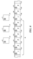
- FIG. 4 is a schematic diagram illustrating an exemplary series of frames created by the encoder shown in FIG. 2 along with their associated reference frames.
- the series of frames includes by example nine frames 60 a - 60 i .
- An “I” in frame 60 a and in frame 60 g indicates that blocks of the respective frame are to be intra-coded
- a “P” in frames 60 b - 60 f , 60 h and 60 i indicates that blocks of the frame are to be inter-coded using one of the last frame (i.e., the next previous frame), alternate reference frame 66 and golden frame 74 .
- frames including blocks that are bi-directionally encoded can be used with embodiments of the present invention, this example does not include them.
- the selection of coding modes and the creation of alternate reference frame 66 could be performed by encoder 20 during a first pass as described previously.
- macroblocks 62 a - 62 i are identified, which are located at the same corresponding spatial position in each frame.
- Spatial correspondence means a pixel, macroblock or other partition has the same or corresponding position from one frame to another, and spatial corresponding blocks are used in the example below.
- the blocks used for the comparisons and calculations are not limited to blocks in the respective frames that spatially correspond to each other.
- the spatial positions of the selected blocks may be different because of motion compensation or other predictive techniques (such as using a constructed reference frame of a different size from the frames to be encoded). Accordingly, the comparisons occur between blocks that are associated with each other, whether that includes spatial correspondence or correspondence with motion compensation and/or consideration of the predictive technique.
- Motion compensation for example, can be used selectively where the target macroblock was encoded in a preceding pass with an intra mode, an inter mode with a non zero motion vector or with 0,0 inter-frame coding where the correlation is below a predetermined threshold.
- alternate reference period 64 is also shown in FIG. 4 and defines the sequence of frames over which alternate reference frame 66 is available for use in prediction.
- alternate reference period 64 is defined by a filter set used to create that alternate reference frame 66 .
- alternate reference period 64 includes frames 60 a - 60 f and macroblocks 62 a - 62 f and corresponds to an I-frame sequence (e.g., a sequence of frames starting with an I-frame and including frames up to but not including the next I-frame in the sequence).
- alternate reference period 64 may be defined as including any number of frames, including a larger number or a smaller number of frames as compared to this example. Alternate reference period 64 may or may not start with an I-frame.
- Alternate reference frame 66 includes an alternate reference block 68 spatially corresponding to macroblocks 62 a - 62 f .
- Golden frame 74 includes a golden frame reference block 76 spatially corresponding to macroblocks 62 a - 62 f.
- a secondary alternate reference frame 70 is also shown next to alternate reference frame 66 . Similar to alternate reference frame 66 , secondary alternate reference frame 70 includes a secondary alternate reference block 72 spatially corresponding to macroblocks 62 a - 62 f . Alternately, a secondary alternate reference frame 70 may not be completely created, but only one or more secondary alternate reference blocks such as secondary alternate reference block 72 may be created. The creation of secondary alternate reference blocks is detailed further hereinafter. For application to inter-prediction encoding and decoding, if a secondary alternate reference block is created, it will replace the spatially corresponding alternate reference block in the alternate reference frame 66 . But alternatively, secondary alternate reference blocks may be stored and used as predictors separately from the predictor blocks of alternate reference frame 66 .
- FIG. 5 is a simplified flow chart of a method of creating a secondary alternate reference macroblock using the encoder shown in FIG. 2
- FIGS. 6A and 6B are a flow chart illustrating an exemplary embodiment of the method of creating a secondary alternate reference macroblock shown in FIG. 5
- the method shown in FIG. 5 broadly describes the basic steps, while FIGS. 6A and 6B show additional details implementing the basic steps.
- the first step in the method as shown in FIG. 5 is to determine whether the creation of a secondary alternate reference block is advantageous ( 80 ) by comparing an alternate reference block with at least one predictor block for a block to be encoded.
- creating secondary alternate reference block 72 may advantageous if alternate reference block 68 is substantially similar to golden frame reference block 76 . If a secondary alternate reference block 72 would not be advantageous, the method ends with respect to analyzing the current alternate reference block 68 .
- the “most different” block(s) in alternate reference period 64 are selected ( 82 ).
- the term “most different” may encompass a number of different algorithms capable of selecting one or more blocks within alternate reference period 64 that are less similar to alternate reference block 68 than those that are not selected. For example, a fixed number of the least similar blocks may be selected. Alternatively, the half of the blocks in the alternate reference period 64 that are most dissimilar could be selected.
- any selected blocks are combined to create secondary alternate reference block 72 ( 84 ).
- This combination could be accomplished by blurring. For example, blurring may be performed by averaging each spatially corresponding individual pixel from each of the selected blocks. The blur may also utilize a weighted average where certain selected blocks may have a higher weighting than others. Other ways of combining the blocks, if desirable, can be used.
- Secondary alternate reference block 72 replaces original alternate reference block 68 , or alternatively, secondary alternate reference block 72 is added as an additional possible predictor block for blocks to be encoded. As explained in detail below, this process can be repeated for each block of alternate reference frame 66 and/or for each block of a frame to be encoded.
- the first step is to select a macroblock (the “target macroblock”) in the current frame being processed (the “target frame”) ( 100 ).
- the target macroblock could be macroblock 62 b in target frame 60 b .
- An alt ref block is then calculated for the target macroblock ( 102 ).
- the alt ref block may be, for example, created using the exemplary embodiment of temporal filter 40 disclosed above.
- the alt ref block may also be created using other filters or algorithms.
- the alt ref block could be created by compositing blocks from several past and future frames, with appropriate motion compensation, or it could contain arbitrary elements such as graphic overlays.
- alt ref block 68 is selected ( 102 ) as it is the spatially corresponding block to target macroblock 62 b.
- the golden frame reference block associated with the target block is selected ( 104 ). In this example, this would be golden frame reference block 76 , as it is the block in golden frame 74 that spatially corresponds with macroblock 62 b.
- processing After the golden frame reference block is selected ( 104 ), processing initializes a variable maxgfdiff to zero ( 106 ).
- the variable maxgfdiff is also called error maxgfdiff and its use is described in more detail hereinafter.
- the difference between the alt ref block and the golden frame reference block is then calculated and compared to a threshold ( 108 ).
- the difference may be calculated using the sum of absolute differences (SAD) algorithm based on a pixel-by-pixel comparison.
- the difference may be alternatively be calculated using other methods, including but not limited to the sum of absolute transformed differences (SATD) or the sum of squared differences (SSD).
- the threshold is an arbitrary number that may be a constant or set by the encoder 20 using various criteria, including but not limited to block size and the difference algorithm used.
- the process ends and no alternative to the alt ref block is created for use by encoder 20 for spatially corresponding target blocks in an alternate reference period, in this example at least blocks 62 b - 62 f in alternate reference period 64 .
- processing selects a first available frame within the frames of interest ( 112 ), generally those in the alternate reference period, to continue the process of determining a secondary alternate reference block.
- a macroblock that spatially corresponds with the target macroblock is selected from the selected frame for the next processing steps.
- a difference, error gfdiff, between the golden frame reference block and the selected macroblock is calculated ( 114 ). As disclosed with respect to the calculation of differences above ( 108 ), the difference may be calculated here using SAD or other methods. Error gfdiff is then compared to error maxgfdiff ( 116 ).
- error maxgfdiff is set as the current value of error gfdiff ( 118 ).
- the currently selected macroblock is then selected as the maximally different block ( 120 ). If instead error gfdiff is less than error maxgfdiff ( 116 ), error maxgfdiff remains unchanged. Whether error maxgfdiff is updated or not, processing advances to determine whether there are additional frames available in the alternate reference period ( 122 ).
- next frame in the alternate reference period and its macroblock spatially corresponding to the target macroblock are selected ( 112 ) to repeat the steps of calculating error gfdiff ( 114 ) and comparing it to error maxgfdiff ( 116 ) to determine whether to update error maxgfdiff and the maximally different block.
- processing initializes a counter variable, countwins, to zero ( 124 ). At the end of this processing, the maximally different block of all spatially corresponding blocks in the sequence of frames is known.
- processing performs several steps to determine how many and for which of the macroblocks a new alt ref block would be better than the existing alt ref block. This is performed in FIG. 6B by comparing the blocks in the sequence of frames that are associated with the target macroblock with both the golden frame reference block and the maximally different block.
- the association between the blocks used in this example is that the blocks spatially correspond to each other, but the selection of blocks for the comparisons are not so limited in practice.
- the first available frame within the sequence of frames is again selected, as is the macroblock in that frame that spatially corresponds to the target macroblock ( 130 ).
- error gfdiff variable is again calculated for the selected macroblock ( 132 ).
- error gfdiff variable is calculated as the difference between the golden frame reference block and the currently-selected macroblock using SAD or other methods.
- a variable afdiff is calculated as the difference between the maximally different block and the currently-selected macroblock ( 134 ). As described previously, the difference may be calculated using SAD or other methods.
- Variable afdiff is next compared with error gfdiff ( 136 ). If the value of variable afdiff is less than the value of error gfdiff, counter countwins variable is incremented ( 138 ). The current selected macroblock is then added to a list of macroblocks that can be used to create the secondary alternate reference block ( 140 ), where the list preferably already includes the maximally different block. If instead the value of variable afdiff is greater than or equal to the value of error gfdiff ( 136 ), processing advances without incrementing counter countwins and adding to the list.
- variable afdiff is less than error gfdiff or not ( 136 )
- a check is made as to whether there are any additional frames available to process in the alternate reference period ( 142 ). Until there are no additional frames ( 142 ), processing continues by selecting the next frame and associated macroblock ( 130 ), calculating error gfdiff and variable afdiff ( 132 , 134 ) and comparing them ( 136 ) to determine whether or not to increment counter countwins ( 138 ) and to add the current macroblock to the list ( 140 ).
- the threshold value is an arbitrary number that is used to determine whether creating the secondary alt ref block should be done or not. That is, if the number of blocks is not sufficiently high, as represented by counter countwins, the additional bits needed to encode yet another alt ref block in the bitstream are not considered to be worth the benefit of having that alt ref block.
- the threshold value may be a constant, such as 2 blocks, or be set by the encoder 20 using various criteria, including but not limited to encoder quality settings and previous prediction results.
- the process ends. No secondary alt ref block is created, and the unaltered alt ref block remains available as one option for encoder 20 to encode blocks.
- the selected blocks in the list are combined, such as by blurring or in other ways as described previously, to create the secondary alt ref block ( 146 ).
- the maximally different block could be used as the center block of a plurality of selected blocks in a process using a temporal filter. The process then ends.
- the secondary alt ref block so created can replace the spatially corresponding alt ref block originally selected ( 102 ).
- the secondary alt ref block could be added as one more possible predictor block for blocks to be encoded. Note that once the process is completed for a target macroblock, it does not have to be repeated for any spatially corresponding block in the sequence of frames considered.
- the sec alt reference block was created in consideration of these blocks and is available to them for encoding.
- the process above can be repeated for each block or only certain blocks of the original alternate reference frame for the alternate reference period if the target macroblock does not encompass the entirety of the target frame.
- the preceding technique can include optional features.
- the worst two or three could be used, such as by averaging.
- the worst block i.e., the maximally different block
- the alt ref block could be replaced only after trying the new secondary alt ref block and determining that it provides better prediction for blocks over several frames, such as two or three frames.
- the process described above is implemented in two-pass encoder 20 as described. However, it could be implemented in a single-pass encoder where a number of input frames are buffered in the encoder before that encoder produces a first compressed frame.
- the information collected during the first pass of a two-pass encode process e.g., encoding modes of macroblocks
- encoding can be performed in many different ways and can produce a variety of encoded data formats.
- the above-described embodiments of encoding or decoding may illustrate some exemplary encoding techniques. However, in general, encoding and decoding are understood to include any transformation or any other change of data whatsoever.
- Encoder 20 and/or decoder 42 are implemented in whole or in part by one or more processors which can include computers, servers, or any other computing device or system capable of manipulating or processing information now-existing or hereafter developed including optical processors, quantum processors and/or molecular processors. Suitable processors also include, for example, general purpose processors, special purpose processors, IP cores, ASICS, programmable logic arrays, programmable logic controllers, microcode, firmware, microcontrollers, microprocessors, digital signal processors, memory, or any combination of the foregoing. In the claims, the term “processor” should be understood as including any the foregoing, either singly or in combination. The terms “signal” and “data” are used interchangeably.
- Encoder 20 and/or decoder 42 also include a memory, which can be connected to the processor through, for example, a memory bus.
- the memory may be read only memory or random access memory (RAM) although any other type of storage device can be used.
- the processor receives program instructions and data from the memory, which can be used by the processor for performing the instructions.
- the memory can be in the same unit as the processor or located in a separate unit that is coupled to the processor.
- encoder 20 can be implemented using a general purpose processor with a computer program that, when executed, carries out any of the respective methods, algorithms and/or instructions described herein.
- FIG. 7 illustrates one suitable implementation in which encoder 20 is implemented in a general purpose computer including a central processing unit (CPU) 202 and random access memory (RAM) 204 .
- Decoder 42 is implemented using a general purpose computer including a central processing unit (CPU) 206 and random access memory (RAM) 208 .
- a special purpose processor can be utilized which can contain specialized hardware for carrying out any of the methods, algorithms and/or instructions described herein. Portions of encoder 20 or decoder 42 do not necessarily have to be implemented in the same manner.
- Encoder 20 and decoder 42 can, for example, be implemented in a wide variety of configurations, including for example on servers in a video conference system.
- encoder 20 can be implemented on a server and decoder 42 can be implemented on a device separate from the server, such as a hand-held communications device such as a cell phone.
- encoder 20 can compress content and transmit the compressed content to the communications device, using the Internet for example, as shown in FIG. 7 .
- the communications device can decode the content for playback.
- the communications device can decode content stored locally on the device (i.e. no transmission is necessary).
- Other suitable encoders and/or decoders are available.
- decoder 42 can be on a personal computer rather than a portable communications device.
- encoder 20 or decoder 42 can be realized in hardware, software or any combination thereof. All or a portion of embodiments of the present invention can take the form of a computer program product accessible from, for example, a computer-usable or computer-readable medium.
- a computer-usable or computer-readable medium can be any device that can, for example tangibly contain, store, communicate, and/or transport the program for use by or in connection with any processor.
- the medium can be, for example, an electronic, magnetic, optical, electromagnetic, or a semiconductor device. Other suitable mediums are also available.
Abstract
Description
Claims (20)
Priority Applications (1)
| Application Number | Priority Date | Filing Date | Title |
|---|---|---|---|
| US14/158,958 US9392280B1 (en) | 2011-04-07 | 2014-01-20 | Apparatus and method for using an alternate reference frame to decode a video frame |
Applications Claiming Priority (2)
| Application Number | Priority Date | Filing Date | Title |
|---|---|---|---|
| US13/081,668 US8638854B1 (en) | 2011-04-07 | 2011-04-07 | Apparatus and method for creating an alternate reference frame for video compression using maximal differences |
| US14/158,958 US9392280B1 (en) | 2011-04-07 | 2014-01-20 | Apparatus and method for using an alternate reference frame to decode a video frame |
Related Parent Applications (1)
| Application Number | Title | Priority Date | Filing Date |
|---|---|---|---|
| US13/081,668 Continuation US8638854B1 (en) | 2011-04-07 | 2011-04-07 | Apparatus and method for creating an alternate reference frame for video compression using maximal differences |
Publications (1)
| Publication Number | Publication Date |
|---|---|
| US9392280B1 true US9392280B1 (en) | 2016-07-12 |
Family
ID=49957982
Family Applications (2)
| Application Number | Title | Priority Date | Filing Date |
|---|---|---|---|
| US13/081,668 Active 2032-04-02 US8638854B1 (en) | 2011-04-07 | 2011-04-07 | Apparatus and method for creating an alternate reference frame for video compression using maximal differences |
| US14/158,958 Active 2032-04-23 US9392280B1 (en) | 2011-04-07 | 2014-01-20 | Apparatus and method for using an alternate reference frame to decode a video frame |
Family Applications Before (1)
| Application Number | Title | Priority Date | Filing Date |
|---|---|---|---|
| US13/081,668 Active 2032-04-02 US8638854B1 (en) | 2011-04-07 | 2011-04-07 | Apparatus and method for creating an alternate reference frame for video compression using maximal differences |
Country Status (1)
| Country | Link |
|---|---|
| US (2) | US8638854B1 (en) |
Cited By (2)
| Publication number | Priority date | Publication date | Assignee | Title |
|---|---|---|---|---|
| US20160344790A1 (en) * | 2015-05-20 | 2016-11-24 | Fujitsu Limited | Wireless communication device and wireless communication method |
| CN113452870A (en) * | 2020-03-26 | 2021-09-28 | 腾讯美国有限责任公司 | Video processing method and device |
Families Citing this family (10)
| Publication number | Priority date | Publication date | Assignee | Title |
|---|---|---|---|---|
| US8385404B2 (en) | 2008-09-11 | 2013-02-26 | Google Inc. | System and method for video encoding using constructed reference frame |
| US8638854B1 (en) | 2011-04-07 | 2014-01-28 | Google Inc. | Apparatus and method for creating an alternate reference frame for video compression using maximal differences |
| US11039138B1 (en) * | 2012-03-08 | 2021-06-15 | Google Llc | Adaptive coding of prediction modes using probability distributions |
| US9426459B2 (en) | 2012-04-23 | 2016-08-23 | Google Inc. | Managing multi-reference picture buffers and identifiers to facilitate video data coding |
| US9609341B1 (en) | 2012-04-23 | 2017-03-28 | Google Inc. | Video data encoding and decoding using reference picture lists |
| US9756331B1 (en) | 2013-06-17 | 2017-09-05 | Google Inc. | Advance coded reference prediction |
| JP6637375B2 (en) * | 2016-04-28 | 2020-01-29 | 株式会社ニューフレアテクノロジー | Pattern inspection method and pattern inspection device |
| US10448013B2 (en) * | 2016-12-22 | 2019-10-15 | Google Llc | Multi-layer-multi-reference prediction using adaptive temporal filtering |
| CN108347602B (en) * | 2017-01-22 | 2021-07-30 | 上海澜至半导体有限公司 | Method and apparatus for lossless compression of video data |
| US10951885B2 (en) | 2018-08-30 | 2021-03-16 | Google Llc | Adaptive temporal filtering for alternate frame reference rendering |
Citations (158)
| Publication number | Priority date | Publication date | Assignee | Title |
|---|---|---|---|---|
| US4816906A (en) | 1986-08-29 | 1989-03-28 | Aeg Aktiengesellschaft | Method for motion-compensated frame-to-frame prediction coding |
| US4924310A (en) | 1987-06-02 | 1990-05-08 | Siemens Aktiengesellschaft | Method for the determination of motion vector fields from digital image sequences |
| US5148269A (en) | 1990-07-20 | 1992-09-15 | U.S. Philips Corporation | Motion vector processing device |
| US5337086A (en) | 1991-10-22 | 1994-08-09 | Sony Corporation | Image signal coding and decoding apparatus with multiple-process motion compensation |
| US5371841A (en) | 1992-07-31 | 1994-12-06 | Eastman Kodak Company | Progressive bit plane reconstruction method |
| US5389068A (en) | 1992-09-01 | 1995-02-14 | Kimberly-Clark Corporation | Tampon applicator |
| US5398068A (en) | 1993-09-02 | 1995-03-14 | Trustees Of Princeton University | Method and apparatus for determining motion vectors for image sequences |
| US5442458A (en) | 1991-12-18 | 1995-08-15 | Eastman Kodak Company | Method and associated apparatus for encoding bitplanes for improved coding efficiency |
| US5461423A (en) | 1992-05-29 | 1995-10-24 | Sony Corporation | Apparatus for generating a motion vector with half-pixel precision for use in compressing a digital motion picture signal |
| US5483287A (en) | 1992-06-19 | 1996-01-09 | General Electric Company | Method for forming transport cells for conveying compressed video data |
| US5485279A (en) | 1992-07-03 | 1996-01-16 | Sony Corporation | Methods and systems for encoding and decoding picture signals and related picture-signal records |
| US5512952A (en) | 1991-09-20 | 1996-04-30 | Sony Corporation | Picture signal encoding and/or decoding apparatus |
| US5568200A (en) | 1995-06-07 | 1996-10-22 | Hitachi America, Ltd. | Method and apparatus for improved video display of progressively refreshed coded video |
| US5576767A (en) | 1993-02-03 | 1996-11-19 | Qualcomm Incorporated | Interframe video encoding and decoding system |
| US5586285A (en) | 1993-02-19 | 1996-12-17 | Intel Corporation | Method and circuitry for increasing reserve memory in a solid state memory disk |
| US5686962A (en) | 1994-07-30 | 1997-11-11 | Samsung Electronics Co., Ltd. | Motion image coder using pre-filter to reduce quantization error |
| US5717394A (en) | 1993-02-10 | 1998-02-10 | Ricoh Company Ltd. | Method and apparatus for encoding and decoding data |
| US5731840A (en) | 1995-03-10 | 1998-03-24 | Kabushiki Kaisha Toshiba | Video coding/decoding apparatus which transmits different accuracy prediction levels |
| US5748789A (en) | 1996-10-31 | 1998-05-05 | Microsoft Corporation | Transparent block skipping in object-based video coding systems |
| US5767909A (en) | 1995-03-28 | 1998-06-16 | Daewoo Electronics, Co., Ltd. | Apparatus for encoding a digital video signal using an adaptive scanning technique |
| EP0634873B1 (en) | 1993-07-15 | 1998-09-09 | NOKIA TECHNOLOGY GmbH | Method to determine the motion vectors in small picture segments of a television picture |
| US5818536A (en) | 1995-09-29 | 1998-10-06 | U.S. Philips Corporation | Motion vector selection using a cost function relating accuracy to bit rate |
| US5886742A (en) | 1995-01-12 | 1999-03-23 | Sharp Kabushiki Kaisha | Video coding device and video decoding device with a motion compensated interframe prediction |
| US5912676A (en) | 1996-06-14 | 1999-06-15 | Lsi Logic Corporation | MPEG decoder frame memory interface which is reconfigurable for different frame store architectures |
| US5926226A (en) | 1996-08-09 | 1999-07-20 | U.S. Robotics Access Corp. | Method for adjusting the quality of a video coder |
| JPH11262018A (en) | 1998-03-09 | 1999-09-24 | Victor Co Of Japan Ltd | Motion compensation coder, motion compensation coding method and motion compensation recording medium therefor |
| JPH11289544A (en) | 1998-04-02 | 1999-10-19 | Sony Corp | Motion detector and its method |
| JPH11513205A (en) | 1995-07-11 | 1999-11-09 | テレフオンアクチーボラゲツト エル エム エリクソン(パブル) | Video coding device |
| JPH11313332A (en) | 1999-03-12 | 1999-11-09 | Rca Thomson Licensing Corp | Video signal compression/release device for even number and odd number field data compressed independently |
| US5991447A (en) | 1997-03-07 | 1999-11-23 | General Instrument Corporation | Prediction and coding of bi-directionally predicted video object planes for interlaced digital video |
| US5999641A (en) | 1993-11-18 | 1999-12-07 | The Duck Corporation | System for manipulating digitized image objects in three dimensions |
| US6005980A (en) | 1997-03-07 | 1999-12-21 | General Instrument Corporation | Motion estimation and compensation of video object planes for interlaced digital video |
| US6075875A (en) | 1996-09-30 | 2000-06-13 | Microsoft Corporation | Segmentation of image features using hierarchical analysis of multi-valued image data and weighted averaging of segmentation results |
| US6084912A (en) | 1996-06-28 | 2000-07-04 | Sarnoff Corporation | Very low bit rate video coding/decoding method and apparatus |
| US6108383A (en) | 1997-07-15 | 2000-08-22 | On2.Com, Inc. | Method and apparatus for compression and decompression of video images |
| US6115076A (en) | 1999-04-20 | 2000-09-05 | C-Cube Semiconductor Ii, Inc. | Compressed video recording device with non-destructive effects addition |
| US6181822B1 (en) | 1993-05-12 | 2001-01-30 | The Duck Corporation | Data compression apparatus and method |
| US6222174B1 (en) | 1999-03-05 | 2001-04-24 | Hewlett-Packard Company | Method of correlating immediately acquired and previously stored feature information for motion sensing |
| US6236682B1 (en) | 1993-03-08 | 2001-05-22 | Sony Corporation | Video motion vector detection including rotation and/or zoom vector generation |
| US6272179B1 (en) | 1998-03-05 | 2001-08-07 | Matsushita Electric Industrial Company, Limited | Image coding apparatus, image decoding apparatus, image coding method, image decoding method, and data storage medium |
| US6289049B1 (en) | 1997-07-30 | 2001-09-11 | Lg Electronics Inc. | Method for coding motion vector in moving picture |
| US6292837B1 (en) | 1997-10-30 | 2001-09-18 | Daniel Miller | Apparatus and method for non-sequential image data transmission and display |
| US20010022815A1 (en) | 1995-05-26 | 2001-09-20 | Rohit Agarwal | Temporal tile staggering for block based video compression |
| US6327304B1 (en) | 1993-05-12 | 2001-12-04 | The Duck Corporation | Apparatus and method to digitally compress video signals |
| US20020031272A1 (en) | 1997-11-17 | 2002-03-14 | Daniele Bagni | Motion-compensated predictive image encoding and decoding |
| US6359929B1 (en) | 1997-07-04 | 2002-03-19 | Matsushita Electric Industrial Co., Ltd. | Image predictive decoding method, image predictive decoding apparatus, image predictive coding apparatus, and data storage medium |
| WO2001050770A3 (en) | 1999-12-28 | 2002-03-21 | Sony Electronics Inc | Methods and apparatus for motion estimation using neighboring macroblocks |
| US20020036705A1 (en) | 2000-06-13 | 2002-03-28 | Samsung Electronics Co., Ltd. | Format converter using bi-directional motion vector and method thereof |
| US6381277B1 (en) | 1997-12-12 | 2002-04-30 | Hyundai Electronics Ind. Co, Ltd. | Shaped information coding device for interlaced scanning video and method therefor |
| US20020071485A1 (en) | 2000-08-21 | 2002-06-13 | Kerem Caglar | Video coding |
| US20020118295A1 (en) | 2001-01-03 | 2002-08-29 | Marta Karczewicz | Video decoder architecture and method for using same |
| US20020172289A1 (en) | 2001-03-08 | 2002-11-21 | Kozo Akiyoshi | Image coding method and apparatus and image decoding method and apparatus |
| WO2003026315A1 (en) | 2001-09-14 | 2003-03-27 | Ntt Docomo, Inc. | Coding method, decoding method, coding apparatus, decoding apparatus, image processing system, coding program, and decoding program |
| US20030081850A1 (en) | 2001-09-14 | 2003-05-01 | Nokia Corporation | Method and system for context-based adaptive binary arithmetic coding |
| US6560366B1 (en) | 1995-12-16 | 2003-05-06 | Paul Gordon Wilkins | Method for analyzing the content of a video signal |
| US20030123545A1 (en) | 1999-04-17 | 2003-07-03 | Pulsent Corporation | Segment-based encoding system using segment hierarchies |
| US20030165331A1 (en) | 2002-03-04 | 2003-09-04 | Philips Electronics North America Corporation | Efficiency FGST framework employing higher quality reference frames |
| WO2003084235A1 (en) | 2002-03-28 | 2003-10-09 | British Telecommunications Public Limited Company | Video pre-processing |
| US20030202594A1 (en) | 2002-03-15 | 2003-10-30 | Nokia Corporation | Method for coding motion in a video sequence |
| US20030215014A1 (en) | 2002-04-10 | 2003-11-20 | Shinichiro Koto | Video encoding method and apparatus and video decoding method and apparatus |
| US6658618B1 (en) | 1999-09-02 | 2003-12-02 | Polycom, Inc. | Error recovery method for video compression coding using multiple reference buffers and a message channel |
| US6661842B1 (en) | 2000-09-22 | 2003-12-09 | General Dynamics Decision Systems, Inc. | Methods and apparatus for error-resilient video coding |
| US20040013308A1 (en) | 2002-07-18 | 2004-01-22 | Lg Electronics Inc. | Calculation method for prediction motion vector |
| US20040037357A1 (en) | 2002-06-11 | 2004-02-26 | Stmicroelectronics S.R.I. | Method and apparatus for variable bit-rate control in video encoding systems and computer program product therefor |
| US20040042549A1 (en) | 2002-08-27 | 2004-03-04 | Hsiang-Chun Huang | Architecture and method for fine granularity scalable video coding |
| US6711211B1 (en) | 2000-05-08 | 2004-03-23 | Nokia Mobile Phones Ltd. | Method for encoding and decoding video information, a motion compensated video encoder and a corresponding decoder |
| US20040080669A1 (en) | 2002-01-18 | 2004-04-29 | Takeshi Nagai | Picture encoding method and apparatus and picture decoding method and apparatus |
| US6735249B1 (en) | 1999-08-11 | 2004-05-11 | Nokia Corporation | Apparatus, and associated method, for forming a compressed motion vector field utilizing predictive motion coding |
| US6774924B2 (en) | 2001-08-24 | 2004-08-10 | Canon Kabushiki Kaisha | Scanning optical device with single lens scanning optical element |
| US6774929B1 (en) | 2000-11-03 | 2004-08-10 | Avotec Inc. | Shielded video projection system for MRI |
| US20040184533A1 (en) | 1997-03-14 | 2004-09-23 | Microsoft Corporation | Motion video signal encoder and encoding method |
| US20040202252A1 (en) | 2003-04-08 | 2004-10-14 | Lg Electronics Inc. | Block error compensating apparatus of image frame and method thereof |
| US20040228410A1 (en) | 2003-05-12 | 2004-11-18 | Eric Ameres | Video compression method |
| GB2403618A (en) | 2000-05-10 | 2005-01-05 | Picturetel Corp | Video coding using multiple buffers |
| US20050008240A1 (en) | 2003-05-02 | 2005-01-13 | Ashish Banerji | Stitching of video for continuous presence multipoint video conferencing |
| US20050031030A1 (en) | 2002-04-16 | 2005-02-10 | Shinya Kadono | Picture encoding method and image decoding method |
| US20050123056A1 (en) | 2003-10-14 | 2005-06-09 | Ye Kui Wang | Encoding and decoding of redundant pictures |
| US6909749B2 (en) | 2002-07-15 | 2005-06-21 | Pts Corporation | Hierarchical segment-based motion vector encoding and decoding |
| US20050147167A1 (en) | 2003-12-24 | 2005-07-07 | Adriana Dumitras | Method and system for video encoding using a variable number of B frames |
| US20050185045A1 (en) | 2002-06-12 | 2005-08-25 | Othon Kamariotis | Video pre-processing |
| US20050207490A1 (en) | 2004-03-18 | 2005-09-22 | Wang Jason N | Stored picture index for AVC coding |
| US20050226321A1 (en) | 2004-03-31 | 2005-10-13 | Yi-Kai Chen | Method and system for two-pass video encoding using sliding windows |
| US20050259736A1 (en) | 2004-05-21 | 2005-11-24 | Christopher Payson | Video decoding for motion compensation with weighted prediction |
| US20050286629A1 (en) | 2004-06-25 | 2005-12-29 | Adriana Dumitras | Coding of scene cuts in video sequences using non-reference frames |
| US6985527B2 (en) | 2001-03-07 | 2006-01-10 | Pts Corporation | Local constraints for motion matching |
| US20060050695A1 (en) | 2004-09-07 | 2006-03-09 | Nokia Corporation | System and method for using redundant representations in streaming applications |
| US20060050149A1 (en) | 2004-09-08 | 2006-03-09 | Heinrich Lang | Mobile wireless camera system |
| US20060062481A1 (en) | 2004-09-21 | 2006-03-23 | Markus Suvanto | Apparatuses, computer program product and method for bit rate control of digital image encoder |
| US7027654B1 (en) | 2001-08-16 | 2006-04-11 | On2 Technologies | Video compression system |
| US20060083300A1 (en) | 2004-10-18 | 2006-04-20 | Samsung Electronics Co., Ltd. | Video coding and decoding methods using interlayer filtering and video encoder and decoder using the same |
| US7050503B2 (en) | 1999-04-17 | 2006-05-23 | Pts Corporation | Segment-based encoding system using residue coding by basis function coefficients |
| US20060126734A1 (en) | 2004-12-14 | 2006-06-15 | Thomas Wiegand | Video encoder and method for encoding a video signal |
| US20060159174A1 (en) | 2003-12-22 | 2006-07-20 | Nec Corporation | Method and device for encoding moving picture |
| WO2006078115A1 (en) | 2005-01-21 | 2006-07-27 | Samsung Electronics Co., Ltd. | Video coding method and apparatus for efficiently predicting unsynchronized frame |
| US20060198443A1 (en) | 2005-03-01 | 2006-09-07 | Yi Liang | Adaptive frame skipping techniques for rate controlled video encoding |
| US20060285598A1 (en) | 2005-06-17 | 2006-12-21 | Jarno Tulkki | Apparatuses, computer program product and method for digital image quality improvement |
| US20070009034A1 (en) | 2005-07-05 | 2007-01-11 | Jarno Tulkki | Apparatuses, computer program product, and method for digital image processing |
| US20070019730A1 (en) | 2005-07-19 | 2007-01-25 | Samsung Electronics Co., Ltd. | Video encoding/decoding method and apparatus in temporal direct mode in hierarchical structure |
| US20070092010A1 (en) | 2005-10-25 | 2007-04-26 | Chao-Tsung Huang | Apparatus and method for motion estimation supporting multiple video compression standards |
| US20070109409A1 (en) | 2004-12-17 | 2007-05-17 | Sehoon Yea | Method and System for Processing Multiview Videos for View Synthesis using Skip and Direct Modes |
| US20070130755A1 (en) | 2005-10-31 | 2007-06-14 | Duquette David W | Electronics assembly machine with embedded solder paste inspection |
| US20070177665A1 (en) | 2006-02-02 | 2007-08-02 | Zhi Zhou | Picture layer rate control for video encoding |
| US7253831B2 (en) | 2000-05-10 | 2007-08-07 | Polycom, Inc. | Video coding using multiple buffers |
| US20070199011A1 (en) | 2006-02-17 | 2007-08-23 | Sony Corporation | System and method for high quality AVC encoding |
| US20070201559A1 (en) | 2006-02-24 | 2007-08-30 | Freescale Semiconductor Inc. | Flexible macroblock odering with reduced data traffic and power consumption |
| US20070206673A1 (en) | 2005-12-08 | 2007-09-06 | Stephen Cipolli | Systems and methods for error resilience and random access in video communication systems |
| US20070211798A1 (en) | 2004-04-02 | 2007-09-13 | Boyce Jill M | Method And Apparatus For Complexity Scalable Video Decoder |
| US20070230563A1 (en) | 2006-04-04 | 2007-10-04 | Qualcomm Incorporated | Adaptive encoder-assisted frame rate up conversion |
| WO2008008331A2 (en) | 2006-07-11 | 2008-01-17 | Thomson Licensing | Methods and apparatus using virtual reference pictures |
| US20080115185A1 (en) | 2006-10-31 | 2008-05-15 | Microsoft Corporation | Dynamic modification of video properties |
| US20080112486A1 (en) | 2006-11-13 | 2008-05-15 | Hitachi, Ltd. | Encoding apparatus and encoding method |
| US20080130755A1 (en) | 2006-11-02 | 2008-06-05 | Qualcomm Incorporated | Apparatus and method of reduced reference frame search in video encoding |
| US7406053B2 (en) | 2004-12-13 | 2008-07-29 | Hewlett-Packard Development Company, L.P. | Methods and systems for controlling the number of computations involved in computing the allocation of resources given resource constraints |
| US20080219351A1 (en) | 2005-07-18 | 2008-09-11 | Dae-Hee Kim | Apparatus of Predictive Coding/Decoding Using View-Temporal Reference Picture Buffers and Method Using the Same |
| US7430261B2 (en) | 2002-04-16 | 2008-09-30 | Robert Bosch Gmbh | Method and bit stream decoding unit using majority voting |
| US20080273599A1 (en) | 2007-05-02 | 2008-11-06 | Samsung Electronics Co., Ltd. | Method and apparatus for encoding and decoding multi-view video data |
| US20080317138A1 (en) | 2007-06-20 | 2008-12-25 | Wei Jia | Uniform video decoding and display |
| US20090028247A1 (en) | 2007-07-02 | 2009-01-29 | Lg Electronics Inc. | Digital broadcasting system and data processing method |
| US7499492B1 (en) | 2004-06-28 | 2009-03-03 | On2 Technologies, Inc. | Video compression and encoding method |
| US20090103610A1 (en) | 2004-02-06 | 2009-04-23 | Apple Inc. | Rate control for video coder employing adaptive linear regression bits modeling |
| US7529199B1 (en) | 2005-05-31 | 2009-05-05 | Cisco Technology, Inc. | System and method for resolving conflicts in proxy routing information associated with multicast distribution trees |
| US20090122859A1 (en) | 2001-05-01 | 2009-05-14 | Sony Corporation | Picture transmission method, picture transmission method program, storage medium which stores picture transmission method program, and picture transmission apparatus |
| US20090148058A1 (en) | 2007-12-10 | 2009-06-11 | Qualcomm Incorporated | Reference selection for video interpolation or extrapolation |
| US20090147856A1 (en) | 2007-12-05 | 2009-06-11 | Samsung Electronics Co., Ltd. | Variable color format based video encoding and decoding methods and apparatuses |
| US20090154563A1 (en) | 2007-12-18 | 2009-06-18 | Edward Hong | Video codec with shared intra-prediction module and method for use therewith |
| US20090175330A1 (en) | 2006-07-17 | 2009-07-09 | Zhi Bo Chen | Method and apparatus for adapting a default encoding of a digital video signal during a scene change period |
| US20090238269A1 (en) | 2006-07-06 | 2009-09-24 | Purvin Bibhas Pandit | Method and Apparatus for Decoupling Frame Number and/or Picture Order Count (POC) for Multi-View Video Encoding and Decoding |
| US20090238277A1 (en) | 2008-03-18 | 2009-09-24 | Joseph Patrick Meehan | Processing Video Data At A Target Rate |
| US20100061461A1 (en) | 2008-09-11 | 2010-03-11 | On2 Technologies Inc. | System and method for video encoding using constructed reference frame |
| US20100061444A1 (en) | 2008-09-11 | 2010-03-11 | On2 Technologies Inc. | System and method for video encoding using adaptive segmentation |
| US20100061645A1 (en) | 2008-09-11 | 2010-03-11 | On2 Technologies Inc. | System and method for video encoding using adaptive loop filter |
| US20100086027A1 (en) | 2008-10-06 | 2010-04-08 | Qualcomm Incorporated | Efficient prediction mode selection |
| US20100104016A1 (en) | 2007-03-05 | 2010-04-29 | Hirofumi Aoki | Weighted prediction information calculation method, apparatus, and program, and video coding method, apparatus, and program |
| US7728840B2 (en) | 2003-09-04 | 2010-06-01 | Texas Instruments Incorporated | Sliding data buffering for image processing |
| US7734821B2 (en) | 1999-03-12 | 2010-06-08 | Microsoft Corporation | Media coding for loss recovery with remotely predicted data units |
| US20100195721A1 (en) | 2009-02-02 | 2010-08-05 | Microsoft Corporation | Local picture identifier and computation of co-located information |
| US7773677B2 (en) | 2004-02-26 | 2010-08-10 | Lg Electronics Inc. | Image block error concealing apparatus and method using weight filtering in mobile communication system |
| US20100239015A1 (en) | 2006-08-28 | 2010-09-23 | Yao Wang | Method and apparatus for determining expected distortion in decoded video blocks |
| WO2011005624A1 (en) | 2009-07-04 | 2011-01-13 | Dolby Laboratories Licensing Corporation | Encoding and decoding architectures for format compatible 3d video delivery |
| US20110069751A1 (en) | 2009-09-23 | 2011-03-24 | Texas Instruments Incorporated | Method and Apparatus for Determination of Motion Estimation Search Window Area Utilizing Adaptive Sliding Window Algorithm |
| US20110090960A1 (en) | 2008-06-16 | 2011-04-21 | Dolby Laboratories Licensing Corporation | Rate Control Model Adaptation Based on Slice Dependencies for Video Coding |
| US7974233B2 (en) | 2009-07-29 | 2011-07-05 | Wiviu Technology Inc. | Systems and methods for transmitting and receiving data streams with feedback information over a lossy network |
| US20110164684A1 (en) | 2008-09-24 | 2011-07-07 | Sony Corporation | Image processing apparatus and method |
| US8005137B2 (en) | 2005-03-25 | 2011-08-23 | Samsung Electronics Co., Ltd. | Video coding and decoding method using weighted prediction and apparatus for the same |
| US8111752B2 (en) | 2004-06-27 | 2012-02-07 | Apple Inc. | Encoding mode pruning during video encoding |
| US20120063513A1 (en) | 2010-09-15 | 2012-03-15 | Google Inc. | System and method for encoding video using temporal filter |
| US20120189058A1 (en) | 2011-01-24 | 2012-07-26 | Qualcomm Incorporated | Single reference picture list construction for video coding |
| US8284846B2 (en) | 2004-08-10 | 2012-10-09 | Thales | Method for shaping frames of a video sequence |
| US20120257677A1 (en) | 2011-04-07 | 2012-10-11 | Google Inc. | Encoding and decoding motion via image segmentation |
| US8310521B2 (en) | 2007-04-30 | 2012-11-13 | Microsoft Corp. | Insertion of virtual video into live video |
| US20120328005A1 (en) | 2011-06-22 | 2012-12-27 | General Instrument Corporation | Construction of combined list using temporal distance |
| US20130022099A1 (en) | 2011-07-21 | 2013-01-24 | Slipstream Data Inc. | Adaptive filtering based on pattern information |
| US20130114695A1 (en) | 2011-11-07 | 2013-05-09 | Qualcomm Incorporated | Signaling quantization matrices for video coding |
| US20130242046A1 (en) | 2012-03-14 | 2013-09-19 | Qualcomm Incorporated | Disparity vector prediction in video coding |
| US20130279589A1 (en) | 2012-04-23 | 2013-10-24 | Google Inc. | Managing multi-reference picture buffers for video data coding |
| US8638854B1 (en) | 2011-04-07 | 2014-01-28 | Google Inc. | Apparatus and method for creating an alternate reference frame for video compression using maximal differences |
| US20140169449A1 (en) | 2011-07-05 | 2014-06-19 | Telefonaktiebolaget L M Ericsson (Publ) | Reference picture management for layered video |
| US9014266B1 (en) | 2012-06-05 | 2015-04-21 | Google Inc. | Decimated sliding windows for multi-reference prediction in video coding |
-
2011
- 2011-04-07 US US13/081,668 patent/US8638854B1/en active Active
-
2014
- 2014-01-20 US US14/158,958 patent/US9392280B1/en active Active
Patent Citations (170)
| Publication number | Priority date | Publication date | Assignee | Title |
|---|---|---|---|---|
| US4816906A (en) | 1986-08-29 | 1989-03-28 | Aeg Aktiengesellschaft | Method for motion-compensated frame-to-frame prediction coding |
| US4924310A (en) | 1987-06-02 | 1990-05-08 | Siemens Aktiengesellschaft | Method for the determination of motion vector fields from digital image sequences |
| US5148269A (en) | 1990-07-20 | 1992-09-15 | U.S. Philips Corporation | Motion vector processing device |
| US5512952A (en) | 1991-09-20 | 1996-04-30 | Sony Corporation | Picture signal encoding and/or decoding apparatus |
| US5337086A (en) | 1991-10-22 | 1994-08-09 | Sony Corporation | Image signal coding and decoding apparatus with multiple-process motion compensation |
| US5442458A (en) | 1991-12-18 | 1995-08-15 | Eastman Kodak Company | Method and associated apparatus for encoding bitplanes for improved coding efficiency |
| US5461423A (en) | 1992-05-29 | 1995-10-24 | Sony Corporation | Apparatus for generating a motion vector with half-pixel precision for use in compressing a digital motion picture signal |
| US5483287A (en) | 1992-06-19 | 1996-01-09 | General Electric Company | Method for forming transport cells for conveying compressed video data |
| US5485279A (en) | 1992-07-03 | 1996-01-16 | Sony Corporation | Methods and systems for encoding and decoding picture signals and related picture-signal records |
| US5371841A (en) | 1992-07-31 | 1994-12-06 | Eastman Kodak Company | Progressive bit plane reconstruction method |
| US5389068A (en) | 1992-09-01 | 1995-02-14 | Kimberly-Clark Corporation | Tampon applicator |
| US5576767A (en) | 1993-02-03 | 1996-11-19 | Qualcomm Incorporated | Interframe video encoding and decoding system |
| US5717394A (en) | 1993-02-10 | 1998-02-10 | Ricoh Company Ltd. | Method and apparatus for encoding and decoding data |
| US5586285A (en) | 1993-02-19 | 1996-12-17 | Intel Corporation | Method and circuitry for increasing reserve memory in a solid state memory disk |
| US6236682B1 (en) | 1993-03-08 | 2001-05-22 | Sony Corporation | Video motion vector detection including rotation and/or zoom vector generation |
| US6327304B1 (en) | 1993-05-12 | 2001-12-04 | The Duck Corporation | Apparatus and method to digitally compress video signals |
| US6181822B1 (en) | 1993-05-12 | 2001-01-30 | The Duck Corporation | Data compression apparatus and method |
| EP0634873B1 (en) | 1993-07-15 | 1998-09-09 | NOKIA TECHNOLOGY GmbH | Method to determine the motion vectors in small picture segments of a television picture |
| US5398068A (en) | 1993-09-02 | 1995-03-14 | Trustees Of Princeton University | Method and apparatus for determining motion vectors for image sequences |
| US5999641A (en) | 1993-11-18 | 1999-12-07 | The Duck Corporation | System for manipulating digitized image objects in three dimensions |
| US6370267B1 (en) | 1993-11-18 | 2002-04-09 | The Duck Corporation | System for manipulating digitized image objects in three dimensions |
| US5686962A (en) | 1994-07-30 | 1997-11-11 | Samsung Electronics Co., Ltd. | Motion image coder using pre-filter to reduce quantization error |
| KR100213018B1 (en) | 1994-07-30 | 1999-08-02 | 윤종용 | Apparatus for encoding moving picture |
| US5886742A (en) | 1995-01-12 | 1999-03-23 | Sharp Kabushiki Kaisha | Video coding device and video decoding device with a motion compensated interframe prediction |
| US5731840A (en) | 1995-03-10 | 1998-03-24 | Kabushiki Kaisha Toshiba | Video coding/decoding apparatus which transmits different accuracy prediction levels |
| US5767909A (en) | 1995-03-28 | 1998-06-16 | Daewoo Electronics, Co., Ltd. | Apparatus for encoding a digital video signal using an adaptive scanning technique |
| US6473463B2 (en) | 1995-05-26 | 2002-10-29 | Intel Corporation | Temporal tile staggering for block based video compression |
| US20010022815A1 (en) | 1995-05-26 | 2001-09-20 | Rohit Agarwal | Temporal tile staggering for block based video compression |
| US5568200A (en) | 1995-06-07 | 1996-10-22 | Hitachi America, Ltd. | Method and apparatus for improved video display of progressively refreshed coded video |
| JPH11513205A (en) | 1995-07-11 | 1999-11-09 | テレフオンアクチーボラゲツト エル エム エリクソン(パブル) | Video coding device |
| US5818536A (en) | 1995-09-29 | 1998-10-06 | U.S. Philips Corporation | Motion vector selection using a cost function relating accuracy to bit rate |
| US6560366B1 (en) | 1995-12-16 | 2003-05-06 | Paul Gordon Wilkins | Method for analyzing the content of a video signal |
| US5912676A (en) | 1996-06-14 | 1999-06-15 | Lsi Logic Corporation | MPEG decoder frame memory interface which is reconfigurable for different frame store architectures |
| US6084912A (en) | 1996-06-28 | 2000-07-04 | Sarnoff Corporation | Very low bit rate video coding/decoding method and apparatus |
| US5926226A (en) | 1996-08-09 | 1999-07-20 | U.S. Robotics Access Corp. | Method for adjusting the quality of a video coder |
| US6075875A (en) | 1996-09-30 | 2000-06-13 | Microsoft Corporation | Segmentation of image features using hierarchical analysis of multi-valued image data and weighted averaging of segmentation results |
| US5748789A (en) | 1996-10-31 | 1998-05-05 | Microsoft Corporation | Transparent block skipping in object-based video coding systems |
| US6005980A (en) | 1997-03-07 | 1999-12-21 | General Instrument Corporation | Motion estimation and compensation of video object planes for interlaced digital video |
| US5991447A (en) | 1997-03-07 | 1999-11-23 | General Instrument Corporation | Prediction and coding of bi-directionally predicted video object planes for interlaced digital video |
| US20040184533A1 (en) | 1997-03-14 | 2004-09-23 | Microsoft Corporation | Motion video signal encoder and encoding method |
| US6359929B1 (en) | 1997-07-04 | 2002-03-19 | Matsushita Electric Industrial Co., Ltd. | Image predictive decoding method, image predictive decoding apparatus, image predictive coding apparatus, and data storage medium |
| US6108383A (en) | 1997-07-15 | 2000-08-22 | On2.Com, Inc. | Method and apparatus for compression and decompression of video images |
| US6289049B1 (en) | 1997-07-30 | 2001-09-11 | Lg Electronics Inc. | Method for coding motion vector in moving picture |
| US6292837B1 (en) | 1997-10-30 | 2001-09-18 | Daniel Miller | Apparatus and method for non-sequential image data transmission and display |
| US20020031272A1 (en) | 1997-11-17 | 2002-03-14 | Daniele Bagni | Motion-compensated predictive image encoding and decoding |
| US6381277B1 (en) | 1997-12-12 | 2002-04-30 | Hyundai Electronics Ind. Co, Ltd. | Shaped information coding device for interlaced scanning video and method therefor |
| US6272179B1 (en) | 1998-03-05 | 2001-08-07 | Matsushita Electric Industrial Company, Limited | Image coding apparatus, image decoding apparatus, image coding method, image decoding method, and data storage medium |
| JPH11262018A (en) | 1998-03-09 | 1999-09-24 | Victor Co Of Japan Ltd | Motion compensation coder, motion compensation coding method and motion compensation recording medium therefor |
| JPH11289544A (en) | 1998-04-02 | 1999-10-19 | Sony Corp | Motion detector and its method |
| US6222174B1 (en) | 1999-03-05 | 2001-04-24 | Hewlett-Packard Company | Method of correlating immediately acquired and previously stored feature information for motion sensing |
| US7734821B2 (en) | 1999-03-12 | 2010-06-08 | Microsoft Corporation | Media coding for loss recovery with remotely predicted data units |
| JPH11313332A (en) | 1999-03-12 | 1999-11-09 | Rca Thomson Licensing Corp | Video signal compression/release device for even number and odd number field data compressed independently |
| US7050503B2 (en) | 1999-04-17 | 2006-05-23 | Pts Corporation | Segment-based encoding system using residue coding by basis function coefficients |
| US7085319B2 (en) | 1999-04-17 | 2006-08-01 | Pts Corporation | Segment-based encoding system using segment hierarchies |
| US20030123545A1 (en) | 1999-04-17 | 2003-07-03 | Pulsent Corporation | Segment-based encoding system using segment hierarchies |
| US6115076A (en) | 1999-04-20 | 2000-09-05 | C-Cube Semiconductor Ii, Inc. | Compressed video recording device with non-destructive effects addition |
| US6735249B1 (en) | 1999-08-11 | 2004-05-11 | Nokia Corporation | Apparatus, and associated method, for forming a compressed motion vector field utilizing predictive motion coding |
| US6658618B1 (en) | 1999-09-02 | 2003-12-02 | Polycom, Inc. | Error recovery method for video compression coding using multiple reference buffers and a message channel |
| WO2001050770A3 (en) | 1999-12-28 | 2002-03-21 | Sony Electronics Inc | Methods and apparatus for motion estimation using neighboring macroblocks |
| US6711211B1 (en) | 2000-05-08 | 2004-03-23 | Nokia Mobile Phones Ltd. | Method for encoding and decoding video information, a motion compensated video encoder and a corresponding decoder |
| US7253831B2 (en) | 2000-05-10 | 2007-08-07 | Polycom, Inc. | Video coding using multiple buffers |
| GB2403618A (en) | 2000-05-10 | 2005-01-05 | Picturetel Corp | Video coding using multiple buffers |
| US20020036705A1 (en) | 2000-06-13 | 2002-03-28 | Samsung Electronics Co., Ltd. | Format converter using bi-directional motion vector and method thereof |
| US20020071485A1 (en) | 2000-08-21 | 2002-06-13 | Kerem Caglar | Video coding |
| US6661842B1 (en) | 2000-09-22 | 2003-12-09 | General Dynamics Decision Systems, Inc. | Methods and apparatus for error-resilient video coding |
| US6774929B1 (en) | 2000-11-03 | 2004-08-10 | Avotec Inc. | Shielded video projection system for MRI |
| US20020118295A1 (en) | 2001-01-03 | 2002-08-29 | Marta Karczewicz | Video decoder architecture and method for using same |
| US6985527B2 (en) | 2001-03-07 | 2006-01-10 | Pts Corporation | Local constraints for motion matching |
| US20020172289A1 (en) | 2001-03-08 | 2002-11-21 | Kozo Akiyoshi | Image coding method and apparatus and image decoding method and apparatus |
| US20090122859A1 (en) | 2001-05-01 | 2009-05-14 | Sony Corporation | Picture transmission method, picture transmission method program, storage medium which stores picture transmission method program, and picture transmission apparatus |
| US7027654B1 (en) | 2001-08-16 | 2006-04-11 | On2 Technologies | Video compression system |
| US6774924B2 (en) | 2001-08-24 | 2004-08-10 | Canon Kabushiki Kaisha | Scanning optical device with single lens scanning optical element |
| WO2003026315A1 (en) | 2001-09-14 | 2003-03-27 | Ntt Docomo, Inc. | Coding method, decoding method, coding apparatus, decoding apparatus, image processing system, coding program, and decoding program |
| EP1351510A1 (en) | 2001-09-14 | 2003-10-08 | NTT DoCoMo, Inc. | Coding method,decoding method,coding apparatus,decoding apparatus,image processing system,coding program,and decoding program |
| US20030081850A1 (en) | 2001-09-14 | 2003-05-01 | Nokia Corporation | Method and system for context-based adaptive binary arithmetic coding |
| US20040080669A1 (en) | 2002-01-18 | 2004-04-29 | Takeshi Nagai | Picture encoding method and apparatus and picture decoding method and apparatus |
| US20030165331A1 (en) | 2002-03-04 | 2003-09-04 | Philips Electronics North America Corporation | Efficiency FGST framework employing higher quality reference frames |
| US7532808B2 (en) | 2002-03-15 | 2009-05-12 | Nokia Corporation | Method for coding motion in a video sequence |
| US20030202594A1 (en) | 2002-03-15 | 2003-10-30 | Nokia Corporation | Method for coding motion in a video sequence |
| WO2003084235A1 (en) | 2002-03-28 | 2003-10-09 | British Telecommunications Public Limited Company | Video pre-processing |
| US20030215014A1 (en) | 2002-04-10 | 2003-11-20 | Shinichiro Koto | Video encoding method and apparatus and video decoding method and apparatus |
| US7430261B2 (en) | 2002-04-16 | 2008-09-30 | Robert Bosch Gmbh | Method and bit stream decoding unit using majority voting |
| US20050031030A1 (en) | 2002-04-16 | 2005-02-10 | Shinya Kadono | Picture encoding method and image decoding method |
| EP1496706B1 (en) | 2002-04-16 | 2007-12-26 | Matsushita Electric Industrial Co., Ltd. | S-pictures decoding method by buffer reset and PN reordering for continuity. |
| US20040037357A1 (en) | 2002-06-11 | 2004-02-26 | Stmicroelectronics S.R.I. | Method and apparatus for variable bit-rate control in video encoding systems and computer program product therefor |
| US20050185045A1 (en) | 2002-06-12 | 2005-08-25 | Othon Kamariotis | Video pre-processing |
| US6909749B2 (en) | 2002-07-15 | 2005-06-21 | Pts Corporation | Hierarchical segment-based motion vector encoding and decoding |
| US20040013308A1 (en) | 2002-07-18 | 2004-01-22 | Lg Electronics Inc. | Calculation method for prediction motion vector |
| US20040042549A1 (en) | 2002-08-27 | 2004-03-04 | Hsiang-Chun Huang | Architecture and method for fine granularity scalable video coding |
| US20040202252A1 (en) | 2003-04-08 | 2004-10-14 | Lg Electronics Inc. | Block error compensating apparatus of image frame and method thereof |
| US7221710B2 (en) | 2003-04-08 | 2007-05-22 | Lg Electronics Inc. | Block error compensating apparatus of image frame and method thereof |
| US20050008240A1 (en) | 2003-05-02 | 2005-01-13 | Ashish Banerji | Stitching of video for continuous presence multipoint video conferencing |
| US20040228410A1 (en) | 2003-05-12 | 2004-11-18 | Eric Ameres | Video compression method |
| US7728840B2 (en) | 2003-09-04 | 2010-06-01 | Texas Instruments Incorporated | Sliding data buffering for image processing |
| US20050123056A1 (en) | 2003-10-14 | 2005-06-09 | Ye Kui Wang | Encoding and decoding of redundant pictures |
| US20060159174A1 (en) | 2003-12-22 | 2006-07-20 | Nec Corporation | Method and device for encoding moving picture |
| US20050147167A1 (en) | 2003-12-24 | 2005-07-07 | Adriana Dumitras | Method and system for video encoding using a variable number of B frames |
| US20090103610A1 (en) | 2004-02-06 | 2009-04-23 | Apple Inc. | Rate control for video coder employing adaptive linear regression bits modeling |
| US7773677B2 (en) | 2004-02-26 | 2010-08-10 | Lg Electronics Inc. | Image block error concealing apparatus and method using weight filtering in mobile communication system |
| US20050207490A1 (en) | 2004-03-18 | 2005-09-22 | Wang Jason N | Stored picture index for AVC coding |
| US20050226321A1 (en) | 2004-03-31 | 2005-10-13 | Yi-Kai Chen | Method and system for two-pass video encoding using sliding windows |
| US20070211798A1 (en) | 2004-04-02 | 2007-09-13 | Boyce Jill M | Method And Apparatus For Complexity Scalable Video Decoder |
| US20050259736A1 (en) | 2004-05-21 | 2005-11-24 | Christopher Payson | Video decoding for motion compensation with weighted prediction |
| US20050286629A1 (en) | 2004-06-25 | 2005-12-29 | Adriana Dumitras | Coding of scene cuts in video sequences using non-reference frames |
| US8111752B2 (en) | 2004-06-27 | 2012-02-07 | Apple Inc. | Encoding mode pruning during video encoding |
| US7606310B1 (en) | 2004-06-28 | 2009-10-20 | On2 Technologies, Inc. | Video compression and encoding method |
| US7499492B1 (en) | 2004-06-28 | 2009-03-03 | On2 Technologies, Inc. | Video compression and encoding method |
| US8284846B2 (en) | 2004-08-10 | 2012-10-09 | Thales | Method for shaping frames of a video sequence |
| US20060050695A1 (en) | 2004-09-07 | 2006-03-09 | Nokia Corporation | System and method for using redundant representations in streaming applications |
| US20060050149A1 (en) | 2004-09-08 | 2006-03-09 | Heinrich Lang | Mobile wireless camera system |
| US20060062481A1 (en) | 2004-09-21 | 2006-03-23 | Markus Suvanto | Apparatuses, computer program product and method for bit rate control of digital image encoder |
| US20060083300A1 (en) | 2004-10-18 | 2006-04-20 | Samsung Electronics Co., Ltd. | Video coding and decoding methods using interlayer filtering and video encoder and decoder using the same |
| US7406053B2 (en) | 2004-12-13 | 2008-07-29 | Hewlett-Packard Development Company, L.P. | Methods and systems for controlling the number of computations involved in computing the allocation of resources given resource constraints |
| US20060126734A1 (en) | 2004-12-14 | 2006-06-15 | Thomas Wiegand | Video encoder and method for encoding a video signal |
| US20070109409A1 (en) | 2004-12-17 | 2007-05-17 | Sehoon Yea | Method and System for Processing Multiview Videos for View Synthesis using Skip and Direct Modes |
| US7671894B2 (en) | 2004-12-17 | 2010-03-02 | Mitsubishi Electric Research Laboratories, Inc. | Method and system for processing multiview videos for view synthesis using skip and direct modes |
| WO2006078115A1 (en) | 2005-01-21 | 2006-07-27 | Samsung Electronics Co., Ltd. | Video coding method and apparatus for efficiently predicting unsynchronized frame |
| US20060198443A1 (en) | 2005-03-01 | 2006-09-07 | Yi Liang | Adaptive frame skipping techniques for rate controlled video encoding |
| US8005137B2 (en) | 2005-03-25 | 2011-08-23 | Samsung Electronics Co., Ltd. | Video coding and decoding method using weighted prediction and apparatus for the same |
| US7529199B1 (en) | 2005-05-31 | 2009-05-05 | Cisco Technology, Inc. | System and method for resolving conflicts in proxy routing information associated with multicast distribution trees |
| US20060285598A1 (en) | 2005-06-17 | 2006-12-21 | Jarno Tulkki | Apparatuses, computer program product and method for digital image quality improvement |
| US20070009034A1 (en) | 2005-07-05 | 2007-01-11 | Jarno Tulkki | Apparatuses, computer program product, and method for digital image processing |
| US20080219351A1 (en) | 2005-07-18 | 2008-09-11 | Dae-Hee Kim | Apparatus of Predictive Coding/Decoding Using View-Temporal Reference Picture Buffers and Method Using the Same |
| US20070019730A1 (en) | 2005-07-19 | 2007-01-25 | Samsung Electronics Co., Ltd. | Video encoding/decoding method and apparatus in temporal direct mode in hierarchical structure |
| US20070092010A1 (en) | 2005-10-25 | 2007-04-26 | Chao-Tsung Huang | Apparatus and method for motion estimation supporting multiple video compression standards |
| US20070130755A1 (en) | 2005-10-31 | 2007-06-14 | Duquette David W | Electronics assembly machine with embedded solder paste inspection |
| US20070206673A1 (en) | 2005-12-08 | 2007-09-06 | Stephen Cipolli | Systems and methods for error resilience and random access in video communication systems |
| US20070177665A1 (en) | 2006-02-02 | 2007-08-02 | Zhi Zhou | Picture layer rate control for video encoding |
| US20070199011A1 (en) | 2006-02-17 | 2007-08-23 | Sony Corporation | System and method for high quality AVC encoding |
| US20070201559A1 (en) | 2006-02-24 | 2007-08-30 | Freescale Semiconductor Inc. | Flexible macroblock odering with reduced data traffic and power consumption |
| US20070230563A1 (en) | 2006-04-04 | 2007-10-04 | Qualcomm Incorporated | Adaptive encoder-assisted frame rate up conversion |
| US20090238269A1 (en) | 2006-07-06 | 2009-09-24 | Purvin Bibhas Pandit | Method and Apparatus for Decoupling Frame Number and/or Picture Order Count (POC) for Multi-View Video Encoding and Decoding |
| WO2008008331A2 (en) | 2006-07-11 | 2008-01-17 | Thomson Licensing | Methods and apparatus using virtual reference pictures |
| US20090175330A1 (en) | 2006-07-17 | 2009-07-09 | Zhi Bo Chen | Method and apparatus for adapting a default encoding of a digital video signal during a scene change period |
| US20100239015A1 (en) | 2006-08-28 | 2010-09-23 | Yao Wang | Method and apparatus for determining expected distortion in decoded video blocks |
| US20080115185A1 (en) | 2006-10-31 | 2008-05-15 | Microsoft Corporation | Dynamic modification of video properties |
| US20080130755A1 (en) | 2006-11-02 | 2008-06-05 | Qualcomm Incorporated | Apparatus and method of reduced reference frame search in video encoding |
| US20080112486A1 (en) | 2006-11-13 | 2008-05-15 | Hitachi, Ltd. | Encoding apparatus and encoding method |
| US20100104016A1 (en) | 2007-03-05 | 2010-04-29 | Hirofumi Aoki | Weighted prediction information calculation method, apparatus, and program, and video coding method, apparatus, and program |
| US8310521B2 (en) | 2007-04-30 | 2012-11-13 | Microsoft Corp. | Insertion of virtual video into live video |
| US20080273599A1 (en) | 2007-05-02 | 2008-11-06 | Samsung Electronics Co., Ltd. | Method and apparatus for encoding and decoding multi-view video data |
| US20080317138A1 (en) | 2007-06-20 | 2008-12-25 | Wei Jia | Uniform video decoding and display |
| US20090028247A1 (en) | 2007-07-02 | 2009-01-29 | Lg Electronics Inc. | Digital broadcasting system and data processing method |
| US20090147856A1 (en) | 2007-12-05 | 2009-06-11 | Samsung Electronics Co., Ltd. | Variable color format based video encoding and decoding methods and apparatuses |
| US20090148058A1 (en) | 2007-12-10 | 2009-06-11 | Qualcomm Incorporated | Reference selection for video interpolation or extrapolation |
| US20090154563A1 (en) | 2007-12-18 | 2009-06-18 | Edward Hong | Video codec with shared intra-prediction module and method for use therewith |
| US20090238277A1 (en) | 2008-03-18 | 2009-09-24 | Joseph Patrick Meehan | Processing Video Data At A Target Rate |
| US20110090960A1 (en) | 2008-06-16 | 2011-04-21 | Dolby Laboratories Licensing Corporation | Rate Control Model Adaptation Based on Slice Dependencies for Video Coding |
| US20130044817A1 (en) | 2008-09-11 | 2013-02-21 | James Bankoski | System and method for video encoding using constructed reference frame |
| US20100061645A1 (en) | 2008-09-11 | 2010-03-11 | On2 Technologies Inc. | System and method for video encoding using adaptive loop filter |
| US20100061444A1 (en) | 2008-09-11 | 2010-03-11 | On2 Technologies Inc. | System and method for video encoding using adaptive segmentation |
| US20100061461A1 (en) | 2008-09-11 | 2010-03-11 | On2 Technologies Inc. | System and method for video encoding using constructed reference frame |
| US20110164684A1 (en) | 2008-09-24 | 2011-07-07 | Sony Corporation | Image processing apparatus and method |
| US20100086027A1 (en) | 2008-10-06 | 2010-04-08 | Qualcomm Incorporated | Efficient prediction mode selection |
| US20100195721A1 (en) | 2009-02-02 | 2010-08-05 | Microsoft Corporation | Local picture identifier and computation of co-located information |
| WO2011005624A1 (en) | 2009-07-04 | 2011-01-13 | Dolby Laboratories Licensing Corporation | Encoding and decoding architectures for format compatible 3d video delivery |
| US20120092452A1 (en) | 2009-07-04 | 2012-04-19 | Dolby Laboratories Licensing Corporation | Encoding and Decoding Architectures for Format Compatible 3D Video Delivery |
| US7974233B2 (en) | 2009-07-29 | 2011-07-05 | Wiviu Technology Inc. | Systems and methods for transmitting and receiving data streams with feedback information over a lossy network |
| US20110069751A1 (en) | 2009-09-23 | 2011-03-24 | Texas Instruments Incorporated | Method and Apparatus for Determination of Motion Estimation Search Window Area Utilizing Adaptive Sliding Window Algorithm |
| US20120063513A1 (en) | 2010-09-15 | 2012-03-15 | Google Inc. | System and method for encoding video using temporal filter |
| US20120189058A1 (en) | 2011-01-24 | 2012-07-26 | Qualcomm Incorporated | Single reference picture list construction for video coding |
| US20120257677A1 (en) | 2011-04-07 | 2012-10-11 | Google Inc. | Encoding and decoding motion via image segmentation |
| US8638854B1 (en) | 2011-04-07 | 2014-01-28 | Google Inc. | Apparatus and method for creating an alternate reference frame for video compression using maximal differences |
| US20120328005A1 (en) | 2011-06-22 | 2012-12-27 | General Instrument Corporation | Construction of combined list using temporal distance |
| US20140169449A1 (en) | 2011-07-05 | 2014-06-19 | Telefonaktiebolaget L M Ericsson (Publ) | Reference picture management for layered video |
| US20130022099A1 (en) | 2011-07-21 | 2013-01-24 | Slipstream Data Inc. | Adaptive filtering based on pattern information |
| US20130114695A1 (en) | 2011-11-07 | 2013-05-09 | Qualcomm Incorporated | Signaling quantization matrices for video coding |
| US20130242046A1 (en) | 2012-03-14 | 2013-09-19 | Qualcomm Incorporated | Disparity vector prediction in video coding |
| US20130279589A1 (en) | 2012-04-23 | 2013-10-24 | Google Inc. | Managing multi-reference picture buffers for video data coding |
| US9014266B1 (en) | 2012-06-05 | 2015-04-21 | Google Inc. | Decimated sliding windows for multi-reference prediction in video coding |
Non-Patent Citations (64)
| Title |
|---|
| "Implementors' Guide; Series H: Audiovisual and Multimedia Systems; Coding of moving video: Implementors Guide for H.264: Advanced video coding for generic audiovisual services". H.264. International Telecommunication Union. Version 12. Dated Jul. 30, 2010. |
| "Liu, P., et al, ""A fast and novel intra and inter modes decision prediction algorithm for H.264/AVC based-on the characteristics of u macro-block"", 2009 Fifth Inti. Confr. on Intelligent Information Hiding and Multimedia Signal Processing, pp. 286-289,http:/ /i eeexp lore. ieee .o rg/s tamp/stamp .jsp ?tp=&arn umber =533 7 483". |
| "Overview; VP7 Data Format and Decoder". Version 1.5. On2 Technologies, Inc. Dated Mar. 28, 2005. |
| "Series H: Audiovisual and Multimedia Systems; Infrastructure of audiovisual services-Coding of moving video". H.264. Advanced video coding for generic audiovisual services. International Telecommunication Union. Version 11. Dated Mar. 2009. |
| "Series H: Audiovisual and Multimedia Systems; Infrastructure of audiovisual services-Coding of moving video". H.264. Advanced video coding for generic audiovisual services. International Telecommunication Union. Version 12. Dated Mar. 2010. |
| "Series H: Audiovisual and Multimedia Systems; Infrastructure of audiovisual services-Coding of moving video". H.264. Advanced video coding for generic audiovisual services. Version 8. International Telecommunication Union. Dated Nov. 1, 2007. |
| "Series H: Audiovisual and Multimedia Systems; Infrastructure of audiovisual services-Coding of moving video". H.264. Amendment 2: New profiles for professional applications. International Telecommunication Union. Dated Apr. 2007. |
| "Series H: Audiovisual and Multimedia Systems; Infrastructure of audiovisual services-Coding of moving video; Advanced video coding for generic audiovisual services". H.264. Amendment 1: Support of additional colour spaces and removal of the High 4:4:4 Profile. International Telecommunication Union. Dated Jun. 2006. |
| "Series H: Audiovisual and Multimedia Systems; Infrastructure of audiovisual services-Coding of moving video; Advanced video coding for generic audiovisual services". H.264. Version 1. International Telecommunication Union. Dated May 2003. |
| "Series H: Audiovisual and Multimedia Systems; Infrastructure of audiovisual services-Coding of moving video; Advanced video coding for generic audiovisual services". H.264. Version 3. International Telecommunication Union. Dated Mar. 2005. |
| "VP6 Bitstream & Decoder Specification". Version 1.02. On2 Technologies, Inc. Dated Aug. 17, 2006. |
| "VP6 Bitstream & Decoder Specification". Version 1.03. On2 Technologies, Inc. Dated Oct. 29, 2007. |
| "VP8 Data Format and Decoding Guide". WebM Project. Google On2. Dated: Dec. 1, 2010. |
| Athanasios, et al.,"Weighted prediction methods for improved motion compensation," Image Processing (ICIP), 2009 16th IEEE International Conference, Nov. 7, 2009, pp. 1029-1032. |
| Bankoski et al. "Technical Overview of VP8, An Open Source Video Codec for the Web". Dated Jul. 11, 2011. |
| Bankoski et al. "VP8 Data Format and Decoding Guide; draft-bankoski-vp8-bitstream-02" Network Working Group. Dated May 18, 2011. |
| Bankoski, J., Koleszar, J., Quillio, L., Salonen, J., Wilkins, P., and Y. Xu, "VP8 Data Format and Decoding Guide", RFC 6386, Nov. 2011. |
| Bo Hong: "Introduction to H.264", Internet citation, XP002952898, pp. 5, 14-15. |
| Borman S. et al., "Super-Resolution From Image Sequences-A Review", Proceedings of Midwest Symposium on Circuits and Systems, pp. 374-378, Aug. 9, 1998. |
| Carreira, Joao et al. "Constrained Parametric Min-Cuts for Automatic Object Segmentation", 2010 IEEE Conference on Computer Vision and Pattern Recognition (CVPR), San Francisco, CA, Jun. 13-18, 2010. |
| Chen, Michael C., et al.; "Design and Optimization of a Differentially Coded Variable Block Size Motion Compensation System", IEEE 1996, 4 pp. |
| Chen, Xing C., et al.; "Quadtree Based Adaptive Lossy Coding of Motion Vectors", IEEE 1996, 4 pp. |
| Chong Soon Lim et al. Reference Lists for B Pictures Under Low Delay Constraints, 95. MPEG Meeting; Jan. 24, 2011; Jan. 21, 2011. |
| Ebrahimi, Touradj, et al.; "Joint motion estimation and segmentation for very low bitrate video coding", SPIE vol. 2501, 1995, 12 pp. |
| EP127356814 Search Report mailed Oct. 30, 2014. |
| Feng Wu et al, "Efficient Background Video Coding with Static Sprite Generation and Arbitrary-Shape Spatial Prediction Techniques", IEEE Transactions on Circuits and Systems for Video Technology, vol. 13, No. 5, pp. 394-405, May 1, 2003. |
| Girod B. et al., "3-D Image Models and Compression: Synthetic Hybrid or Natural Fit?", International Conference on Image Processing, vol. 2, pp. 525-529, Oct. 24, 1999. |
| Guillotel, Philippe, et al.; "Comparison of motion vector coding techniques", SPIE vol. 2308, 1994, 11 pp. |
| Hiroshi Watanabe et al, "Sprite Coding in Object-Based Video Coding Standard: MPEG-4", Proceedings of Multiconference on Systemics, Cybernetics and Informatics, vol. 13, pp. 420-425, Jul. 1, 2001. |
| International Search Report and Written Opinion for International Patent Application PCT/US2012/031579; dated Jun. 21, 2012. |
| International Search Report dated Apr. 20, 2010 from the corresponding International Application No. PCT/US2009/056448. |
| International Search Report for related matter PCT/US2013/037058 mailed Dec. 16, 2013. |
| IPRP for PCT/US2013/037058 from related application mailed Nov. 6, 2014. |
| Irani M et al, "Video Compression Using Mosaic Representations", Signal Processing Image Communication, vol. 7 No. 4., pp. 529-552, Nov. 1, 1995. |
| ISR & Written Opinion, Re: Application # PCT/US2012/043748;Sep. 14, 2012. |
| Karczewicz, Marta, et al.; "Video Coding Using Motion Compensation With Polynomial Motion Vector Fields", IEEE COMSOC EURASIP, First International Workshop on Wireless Image/Video Communications-Sep. 1996, 6 pp. |
| Kim, Jong Won, et al.; "On the Hierarchical Variable Block Size Motion Estimation Technique for Motion Sequence Coding", SPIE Visual Communication and Image Processing 1993, Cambridge, MA, Nov. 8, 1993, 29 pp. |
| Liu, Bede, et al.; "A simple method to segment motion field for video coding", SPIE vol. 1818, Visual Communications and Image Processing 1992, 10 pp. |
| Liu, Bede, et al.; "New Fast Algorithms for the Estimation of Block Motion Vectors", IEEE Transactions on Circuits and Systems for Video Technology, vol. 3, No. 2, Apr. 1993, 10 pp. |
| Luttrell, Max, et al.; "Simulation Results for Modified Error Resilient Syntax With Data Partitioning and RVLC", ITU-Telecommunications Standardization Sector, Study Group 16, Video Coding Experts Group (Question 15), Sixth Meeting: Seoul, South Korea, Nov. 2, 1998, 34 pp. |
| Martin, Graham R., et al.; "Reduced Entropy Motion Compensation Using Variable Sized Blocks", SPIE vol. 3024, 1997, 10 pp. |
| Mozilla, "Introduction to Video Coding Part 1: Transform Coding", Video Compression Overview, Mar. 2012, 171 pp. |
| Nicolas, H., et al.; "Region-based motion estimation using deterministic relaxation schemes for image sequence coding", IEEE 1992, 4 pp. |
| Nokia, Inc., Nokia Research Center, "MVC Decoder Description", Telecommunication Standardization Sector, Study Period 1997-2000, Geneva, Feb. 7, 2000, 99 pp. |
| ON2 Technologies Inc., White Paper TrueMotion VP7 Video Codec, Jan. 10, 2005, 13 pages, Document Version: 1.0, Clifton Park, New York. |
| ON2 Technologies, Inc., White Paper On2's TrueMotion VP7 Video Codec,Jan. 10, 2005, pp. 13 pages, Document Version:1.0, Clifton Park, New York. |
| Orchard, Michael T.; "Exploiting Scene Structure in Video Coding", IEEE 1991, 5 pp. |
| Orchard, Michael T.; "Predictive Motion-Field Segmentation for Image Sequence Coding", IEEE Transactions on Circuits and Systems for Video Technology, vol. 3, No. 1, Feb. 1993, 17 pp. |
| Park, Jun Sung, et al., "Selective Intra Prediction Mode Decision for H.264/AVC Encoders", World Academy of Science, Engineering and Technology 13, (2006). |
| Schiller, H., et al.; "Efficient Coding of Side Information in a Low Bitrate Hybrid Image Coder", Signal Processing 19 (1990) Elsevier Science Publishers B.V. 61-73, 13 pp. |
| Schuster, Guido M., et al.; "A Video Compression Scheme With Optimal Bit Allocation Among Segmentation, Motion, and Residual Error", IEEE Transactions on Image Processing, vol. 6, No. 11, Nov. 1997, 16 pp. |
| Series H: Audiovisual and Multimedia Systems, Infrastructure of audiovisual services-Coding of moving video, Video coding for low bit rate communication, International Telecommunication Union, ITU-T Recommendation H.263, Feb. 1998, 167 pp. |
| Shen, L., et al. Fast mode decision for multiview video coding, 2009, IEEE, entire document. |
| Steliaros, Michael K., et al.; "Locally-accurate motion estimation for object-based video coding", SPIE vol. 3309, 1997, 11 pp. |
| Stiller, Christoph; "Motion-Estimation for Coding of Moving Video at 8 kbit/s with Gibbs Modeled Vectorfield Smoothing", SPIE vol. 1360 Visual Communications and Image Processing 1990, 9 pp. |
| Strobach, Peter; "Tree-Structured Scene Adaptive Coder", IEEE Transactions on Communications, vol. 38, No. 4, Apr. 1990, 10 pp. |
| Wang et al., On reference picture list construction for uni-predicted partitions, JCT-VC Meeting, MPEG Meeting, Geneva, Mar. 11, 2011. |
| Wiegand, Thomas, et al.; "Rate-Distortion Optimized Mode Selection for Very Low Bit Rate Video Coding and the Emerging H.263 Standard", IEEE Transactions on Circuits and Systems for Video Technology, vol. 6, No. 2, Apr. 1996, 9 pp. |
| Wiegand, Thomas, et al.; Long-Term Memory Motion-Compensated Prediction, date unknown. |
| Wright, R. Glenn, et al.; "Multimedia-Electronic Technical Manual for ATE", IEEE 1996, 3 pp. |
| Written Opinion of the International Searching Authority dated Aug. 8, 2010, from the corresponding International Application No. PCT/US2009/056448 filed Sep. 10, 2009. |
| Yang, H. et al., Optimizing Motion Compensated Prediction for Error Resilient Video Coding, IEE Transactions on Image Processing, vol. 19, No. 1 Jan. 2010, entire document. |
| Zhang, Kui, et al.; "Variable Block Size Video Coding With Motion Prediction and Motion Segmentation", SPIE vol. 2419, 1995, 9 pp. |
| Zhi Liu, Zhaoyang Zhang, Liquan Shen, Mosaic Generation in H.264 Compressed Domain, IEEE 2006. |
Cited By (3)
| Publication number | Priority date | Publication date | Assignee | Title |
|---|---|---|---|---|
| US20160344790A1 (en) * | 2015-05-20 | 2016-11-24 | Fujitsu Limited | Wireless communication device and wireless communication method |
| CN113452870A (en) * | 2020-03-26 | 2021-09-28 | 腾讯美国有限责任公司 | Video processing method and device |
| CN113452870B (en) * | 2020-03-26 | 2024-04-09 | 腾讯美国有限责任公司 | Video processing method and device |
Also Published As
| Publication number | Publication date |
|---|---|
| US8638854B1 (en) | 2014-01-28 |
Similar Documents
| Publication | Publication Date | Title |
|---|---|---|
| US20220303583A1 (en) | Video coding using constructed reference frames | |
| US9392280B1 (en) | Apparatus and method for using an alternate reference frame to decode a video frame | |
| US8665952B1 (en) | Apparatus and method for decoding video encoded using a temporal filter | |
| US8693547B2 (en) | Apparatus and method for coding using motion vector segmentation | |
| US8553769B2 (en) | Method and device for improved multi-layer data compression | |
| US8781004B1 (en) | System and method for encoding video using variable loop filter | |
| US8989256B2 (en) | Method and apparatus for using segmentation-based coding of prediction information | |
| US9106933B1 (en) | Apparatus and method for encoding video using different second-stage transform | |
| US20050013500A1 (en) | Intelligent differential quantization of video coding | |
| KR100694137B1 (en) | Apparatus for encoding or decoding motion image, method therefor, and recording medium storing a program to implement thereof | |
| US8594189B1 (en) | Apparatus and method for coding video using consistent regions and resolution scaling | |
| US8780971B1 (en) | System and method of encoding using selectable loop filters | |
| CA2763489C (en) | Method and device for improved multi-layer data compression | |
| CN116437076A (en) | Apparatus and method for conditional decoder-side motion vector correction in video coding | |
| US11212536B2 (en) | Negative region-of-interest video coding | |
| US20170054977A1 (en) | Video decoding method and apparatus using the same | |
| US8611415B1 (en) | System and method for coding using improved motion estimation | |
| US20150010083A1 (en) | Video decoding method and apparatus using the same | |
| WO2024072438A1 (en) | Motion vector candidate signaling | |
| KR20130050534A (en) | Methods of encoding using hadamard transform and apparatuses using the same |
Legal Events
| Date | Code | Title | Description |
|---|---|---|---|
| AS | Assignment |
Owner name: GOOGLE INC., CALIFORNIA Free format text: ASSIGNMENT OF ASSIGNORS INTEREST;ASSIGNORS:BANKOSKI, JAMES;GRANGE, ADRIAN;WILKINS, PAUL;SIGNING DATES FROM 20110331 TO 20110401;REEL/FRAME:032008/0931 |
|
| STCF | Information on status: patent grant |
Free format text: PATENTED CASE |
|
| AS | Assignment |
Owner name: GOOGLE LLC, CALIFORNIA Free format text: CHANGE OF NAME;ASSIGNOR:GOOGLE INC.;REEL/FRAME:044566/0657 Effective date: 20170929 |
|
| MAFP | Maintenance fee payment |
Free format text: PAYMENT OF MAINTENANCE FEE, 4TH YEAR, LARGE ENTITY (ORIGINAL EVENT CODE: M1551); ENTITY STATUS OF PATENT OWNER: LARGE ENTITY Year of fee payment: 4 |
|
| MAFP | Maintenance fee payment |
Free format text: PAYMENT OF MAINTENANCE FEE, 8TH YEAR, LARGE ENTITY (ORIGINAL EVENT CODE: M1552); ENTITY STATUS OF PATENT OWNER: LARGE ENTITY Year of fee payment: 8 |