US9393683B2 - Conductive boot for power tool protection - Google Patents
Conductive boot for power tool protection Download PDFInfo
- Publication number
- US9393683B2 US9393683B2 US14/702,475 US201514702475A US9393683B2 US 9393683 B2 US9393683 B2 US 9393683B2 US 201514702475 A US201514702475 A US 201514702475A US 9393683 B2 US9393683 B2 US 9393683B2
- Authority
- US
- United States
- Prior art keywords
- power tool
- boot
- housing
- tool assembly
- shield
- Prior art date
- Legal status (The legal status is an assumption and is not a legal conclusion. Google has not performed a legal analysis and makes no representation as to the accuracy of the status listed.)
- Active
Links
- 239000004020 conductor Substances 0.000 claims abstract description 31
- 238000004891 communication Methods 0.000 claims description 39
- 230000001681 protective effect Effects 0.000 claims description 24
- 239000000463 material Substances 0.000 claims description 12
- 238000001228 spectrum Methods 0.000 claims description 4
- 230000001629 suppression Effects 0.000 claims description 4
- 230000004913 activation Effects 0.000 claims 1
- 230000008439 repair process Effects 0.000 abstract description 10
- 238000012423 maintenance Methods 0.000 abstract description 9
- 230000007246 mechanism Effects 0.000 description 19
- PXHVJJICTQNCMI-UHFFFAOYSA-N Nickel Chemical compound [Ni] PXHVJJICTQNCMI-UHFFFAOYSA-N 0.000 description 8
- 239000010949 copper Substances 0.000 description 7
- 239000012636 effector Substances 0.000 description 7
- 239000004744 fabric Substances 0.000 description 6
- 238000009434 installation Methods 0.000 description 6
- 229910052802 copper Inorganic materials 0.000 description 5
- 230000000694 effects Effects 0.000 description 5
- 229920002334 Spandex Polymers 0.000 description 4
- 230000005672 electromagnetic field Effects 0.000 description 4
- 239000000835 fiber Substances 0.000 description 4
- 239000010931 gold Substances 0.000 description 4
- 229910052759 nickel Inorganic materials 0.000 description 4
- 239000002245 particle Substances 0.000 description 4
- 239000004033 plastic Substances 0.000 description 4
- 229920003023 plastic Polymers 0.000 description 4
- 229910052709 silver Inorganic materials 0.000 description 4
- 230000001052 transient effect Effects 0.000 description 4
- 230000000007 visual effect Effects 0.000 description 4
- RYGMFSIKBFXOCR-UHFFFAOYSA-N Copper Chemical compound [Cu] RYGMFSIKBFXOCR-UHFFFAOYSA-N 0.000 description 3
- WHXSMMKQMYFTQS-UHFFFAOYSA-N Lithium Chemical compound [Li] WHXSMMKQMYFTQS-UHFFFAOYSA-N 0.000 description 3
- 229910045601 alloy Inorganic materials 0.000 description 3
- 239000000956 alloy Substances 0.000 description 3
- 230000000712 assembly Effects 0.000 description 3
- 238000000429 assembly Methods 0.000 description 3
- 230000008901 benefit Effects 0.000 description 3
- 230000008878 coupling Effects 0.000 description 3
- 238000010168 coupling process Methods 0.000 description 3
- 238000005859 coupling reaction Methods 0.000 description 3
- 229910052737 gold Inorganic materials 0.000 description 3
- 229910052744 lithium Inorganic materials 0.000 description 3
- 230000033001 locomotion Effects 0.000 description 3
- 238000012360 testing method Methods 0.000 description 3
- 229920002396 Polyurea Polymers 0.000 description 2
- BQCADISMDOOEFD-UHFFFAOYSA-N Silver Chemical compound [Ag] BQCADISMDOOEFD-UHFFFAOYSA-N 0.000 description 2
- 238000005520 cutting process Methods 0.000 description 2
- 238000003780 insertion Methods 0.000 description 2
- 230000037431 insertion Effects 0.000 description 2
- 238000007689 inspection Methods 0.000 description 2
- 239000002184 metal Substances 0.000 description 2
- 229910052751 metal Inorganic materials 0.000 description 2
- 238000000034 method Methods 0.000 description 2
- 239000004332 silver Substances 0.000 description 2
- 239000010944 silver (metal) Substances 0.000 description 2
- 239000004759 spandex Substances 0.000 description 2
- OKTJSMMVPCPJKN-UHFFFAOYSA-N Carbon Chemical compound [C] OKTJSMMVPCPJKN-UHFFFAOYSA-N 0.000 description 1
- 230000005355 Hall effect Effects 0.000 description 1
- 208000014633 Retinitis punctata albescens Diseases 0.000 description 1
- 230000002547 anomalous effect Effects 0.000 description 1
- 238000013459 approach Methods 0.000 description 1
- 230000005540 biological transmission Effects 0.000 description 1
- 229910052799 carbon Inorganic materials 0.000 description 1
- 230000015556 catabolic process Effects 0.000 description 1
- 238000006243 chemical reaction Methods 0.000 description 1
- 239000011248 coating agent Substances 0.000 description 1
- 238000000576 coating method Methods 0.000 description 1
- 239000011231 conductive filler Substances 0.000 description 1
- 238000010276 construction Methods 0.000 description 1
- 238000002788 crimping Methods 0.000 description 1
- 238000013461 design Methods 0.000 description 1
- 238000010586 diagram Methods 0.000 description 1
- 229920001971 elastomer Polymers 0.000 description 1
- 239000000806 elastomer Substances 0.000 description 1
- 239000013536 elastomeric material Substances 0.000 description 1
- 230000005686 electrostatic field Effects 0.000 description 1
- 238000004880 explosion Methods 0.000 description 1
- PCHJSUWPFVWCPO-UHFFFAOYSA-N gold Chemical compound [Au] PCHJSUWPFVWCPO-UHFFFAOYSA-N 0.000 description 1
- 238000010348 incorporation Methods 0.000 description 1
- 238000002347 injection Methods 0.000 description 1
- 239000007924 injection Substances 0.000 description 1
- 238000001746 injection moulding Methods 0.000 description 1
- 239000011810 insulating material Substances 0.000 description 1
- 239000004816 latex Substances 0.000 description 1
- 229920000126 latex Polymers 0.000 description 1
- 238000004519 manufacturing process Methods 0.000 description 1
- 230000013011 mating Effects 0.000 description 1
- 238000012544 monitoring process Methods 0.000 description 1
- 230000003287 optical effect Effects 0.000 description 1
- 230000001151 other effect Effects 0.000 description 1
- 230000035515 penetration Effects 0.000 description 1
- 230000005855 radiation Effects 0.000 description 1
- 238000012552 review Methods 0.000 description 1
- 238000000926 separation method Methods 0.000 description 1
- 229920001187 thermosetting polymer Polymers 0.000 description 1
- 238000012546 transfer Methods 0.000 description 1
- 238000004804 winding Methods 0.000 description 1
Images


Classifications
-
- B—PERFORMING OPERATIONS; TRANSPORTING
- B25—HAND TOOLS; PORTABLE POWER-DRIVEN TOOLS; MANIPULATORS
- B25F—COMBINATION OR MULTI-PURPOSE TOOLS NOT OTHERWISE PROVIDED FOR; DETAILS OR COMPONENTS OF PORTABLE POWER-DRIVEN TOOLS NOT PARTICULARLY RELATED TO THE OPERATIONS PERFORMED AND NOT OTHERWISE PROVIDED FOR
- B25F5/00—Details or components of portable power-driven tools not particularly related to the operations performed and not otherwise provided for
- B25F5/02—Construction of casings, bodies or handles
-
- B—PERFORMING OPERATIONS; TRANSPORTING
- B25—HAND TOOLS; PORTABLE POWER-DRIVEN TOOLS; MANIPULATORS
- B25F—COMBINATION OR MULTI-PURPOSE TOOLS NOT OTHERWISE PROVIDED FOR; DETAILS OR COMPONENTS OF PORTABLE POWER-DRIVEN TOOLS NOT PARTICULARLY RELATED TO THE OPERATIONS PERFORMED AND NOT OTHERWISE PROVIDED FOR
- B25F5/00—Details or components of portable power-driven tools not particularly related to the operations performed and not otherwise provided for
-
- B—PERFORMING OPERATIONS; TRANSPORTING
- B23—MACHINE TOOLS; METAL-WORKING NOT OTHERWISE PROVIDED FOR
- B23D—PLANING; SLOTTING; SHEARING; BROACHING; SAWING; FILING; SCRAPING; LIKE OPERATIONS FOR WORKING METAL BY REMOVING MATERIAL, NOT OTHERWISE PROVIDED FOR
- B23D59/00—Accessories specially designed for sawing machines or sawing devices
- B23D59/001—Measuring or control devices, e.g. for automatic control of work feed pressure on band saw blade
-
- H—ELECTRICITY
- H02—GENERATION; CONVERSION OR DISTRIBUTION OF ELECTRIC POWER
- H02G—INSTALLATION OF ELECTRIC CABLES OR LINES, OR OF COMBINED OPTICAL AND ELECTRIC CABLES OR LINES
- H02G1/00—Methods or apparatus specially adapted for installing, maintaining, repairing or dismantling electric cables or lines
- H02G1/02—Methods or apparatus specially adapted for installing, maintaining, repairing or dismantling electric cables or lines for overhead lines or cables
-
- Y—GENERAL TAGGING OF NEW TECHNOLOGICAL DEVELOPMENTS; GENERAL TAGGING OF CROSS-SECTIONAL TECHNOLOGIES SPANNING OVER SEVERAL SECTIONS OF THE IPC; TECHNICAL SUBJECTS COVERED BY FORMER USPC CROSS-REFERENCE ART COLLECTIONS [XRACs] AND DIGESTS
- Y10—TECHNICAL SUBJECTS COVERED BY FORMER USPC
- Y10T—TECHNICAL SUBJECTS COVERED BY FORMER US CLASSIFICATION
- Y10T408/00—Cutting by use of rotating axially moving tool
- Y10T408/65—Means to drive tool
Definitions
- Various embodiments of the present disclosure are generally directed to the area of high voltage power line maintenance and repair, and more particularly to an improved powered tool arrangement which facilitates power driven maintenance and repair operations adjacent a high voltage power line.
- an apparatus comprises a power tool having a housing which encloses at least an electrical load, such as a motor, and a control electronics module to activate and control the electrical load.
- the housing supporting a first shield as a layer of conductive material that nominally encloses the load and the control electronics module, the first shield open at a battery pack receiving slot of the housing.
- a removable battery pack is mateable with the battery pack receiving slot of the housing to supply electrical power for use by the motor and the control electronics module.
- a protective boot removably connectable to the housing is adapted to surround the removeable battery pack upon engagement with the housing.
- the boot has a second shield as a layer of conductive material which, which installed onto the boot, combines with the first shield to form a combined shield that nominally encloses the power tool and the boot.
- the boot further has at least one locking feature that engages a corresponding feature of the housing to mechanically secure the boot to the housing to retain the boot in said engagement with the housing.
- FIG. 1 is an isometric depiction of a power tool assembly constructed and operated in accordance with various embodiments of the present disclosure.
- FIG. 2 is a graphical representation of exemplary electromagnetic fields an energized high voltage power line (conductor) adjacent which the power tool assembly of FIG. 1 can be operatively used.
- FIG. 4 is a functional block representation of the power tool assembly of FIG. 1 in conjunction with the high voltage power line of FIGS. 2-3 .
- FIG. 5 is an isometric elevational view of a power tool of the arrangement of FIG. 4 , the power tool characterized as a rotary driver.
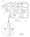
- FIG. 6 is a generalized cross-sectional representation of the power tool of FIG. 5 .
- FIG. 7 is an isometric depiction of the protective boot of FIG. 4 in accordance with some embodiments.
- FIG. 8 is a cross-sectional view of a layer of the protective boot of FIG. 7 .
- FIG. 9 depicts an interface between the housing shield of the power device and the boot shield of the protective boot.
- FIG. 10 represents a conductive shunt contactingly disposed between the housing and boot shields.
- FIG. 11 illustrates on exemplary latching mechanism used to secure the protective boot to the housing of the power tool.
- FIG. 12 is a functional block representation of the power tool and the protective boot, illustrating an optional third conductive shield surrounding control circuitry of the power tool in some embodiments.
- FIG. 13 is a schematic representation of transient suppression circuitry that can be connected between the housing shield and the control circuitry shield of FIG. 12 .
- FIG. 14 illustrates an access aperture in the housing shield operative in some embodiments to facilitate the passage of communication signals between the power tool and the user interface of FIG. 1 .
- FIG. 15 depicts a radio frequency (RF) wireless communication link used in some embodiments.
- RF radio frequency
- FIG. 16 depicts a non-conductive fiber optic communication link used in other embodiments.
- FIG. 17 depicts a shield interlock switch which generates a device enable signal responsive to a detected interlock of the housing and boot shields in accordance with some embodiments.
- FIG. 18 illustrates another exemplary power tool in accordance with some embodiments, the power tool characterized as a powered crimper.
- FIG. 19 illustrates another exemplary power tool in accordance with further embodiments, the power tool characterized as a chain saw.
- FIG. 20 is a schematic representation of an unmanned aerial vehicle (UAV) constructed and operated in accordance with various embodiments.
- UAV unmanned aerial vehicle
- FIG. 21 is a functional block representation of another UAV in accordance with further embodiments.
- FIG. 22 shows another UAV in accordance with further embodiments.
- FIG. 23 shows a mobile line robot in accordance with further embodiments.
- FIG. 24 shows the mobile line robot of FIG. 23 in combination with a delivery UAV in accordance with further embodiments.
- the present disclosure is generally directed to improvements in the manner in which maintenance and repair operations may be carried out adjacent high voltage power lines.
- a problem associated with the use of an electrically powered tool, such as a driver, saw, crimper, etc., mounted to the end of a hot stick is the potential for damage to the tool responsive to coronal discharge as the tool is brought into proximity with the power line.
- many power line maintenance and repair operations have utilized manually operated tools which are mounted to hotsticks and which are manipulated by hand.
- a power tool is mounted to the end of an insulative hotstick.
- the power tool has a housing which encloses at least a motor and an electronic control module. These components are protected from damage as the power tool is brought into proximity with a high voltage power line.
- the housing includes a first electrically conductive shield as a layer of nominally continuous conductive material that surrounds the components disposed therein.
- the power tool utilizes a removably reattachable battery pack, such as NiCAD or lithium rechargeable batteries, to supply electrical power for use during operation of the power tool.
- the battery pack may be a standardized, commercially available pack.
- the housing (and the first shield) may be open at one end to slidingly receive engagement of the battery pack.
- a protective boot comprising a rigid or flexible cover is supplied to cover the battery pack once the battery pack has slidingly engaged the power tool housing.
- the boot includes one or more locking features that establish a positive locking engagement with the housing of the power tool.
- the boot includes a conductive layer that forms a second shield that, combined with the first shield, provides protection to the assembled power tool from coronal discharge. At least one conductive shunting path is established between the first and second shields to form a combined overall shield.
- the boot is flexible and includes a conductive layer of elastomer with embedded conductive particles.
- Affixed to the conductive layer may be an outer layer of elastomeric fabric such as formed of elastane (Spandex) which is a polyurethane-polyurea copolymer or similar material.
- the fabric when used, and more generally, the boot itself, may be provided with an appropriate color such as orange to provide a visual indication for safety personnel to confirm compliance with safety procedures (e.g., installation of the boot). Warning indicia may be printed on the outside of the boot to further ensure compliance.
- the boot can thus provide two primary functions: first, it combines with the first shield of the housing of the power tool to nominally fully enclose the power tool with a conductive shield thereby protecting the assembled power tool from damage resulting from coronal discharge. Second, it separately interlocks with the housing to ensure the battery pack does not inadvertently become dislodged from the housing during manipulation by a user.
- a third shield is provided to enclose and protect the electronic circuit module within the housing.
- This third shield may be coupled to the combined shield formed from the first and second shields by a transient suppression circuit.
- an opening is provided in the combined shield to facilitate a communication link between the electronic control module and a distal control input actuated by a user of the power tool via a user interface at a proximal end of the hot stick.
- the communication link may be a radio frequency (RF) wireless link with a two-way receiver/transmitter module in both the power tool and at the base of a hot stick adapted to support the power tool.
- the operative frequency range of the communication link will generally be on the order of at least 375 MHz.
- the communication link operates at a frequency on the order of around 2.4 GHz or higher.
- the communication link may involve non-conductive cables such as fiber optic strands, laser links, etc.
- the user interface can include a user depressible trigger to vary an amount of power applied to the power tool to, for example, vary torque generated by the tool.
- the user interface may further include one or more LEDs or similar visual indicators to provide status indications to the user such as a powered state of the tool, a state of ongoing communications between the user interface and the tool, etc.
- an interlink mechanism is provided that ensures that the power tool is not operative unless the boot is in place on the battery pack.
- a micro-switch or other mechanism may be used to this end.
- the power tool may be manually manipulated by a human user on the ground or on an adjacent platform
- the power tool is incorporated into an unmanned aerial vehicle (UAV), either directly into the body of the UAV or at the end of an end effector.
- UAV unmanned aerial vehicle
- a user can remotely guide the UAV into a position adjacent the power lines and activate the power tool remotely as required.
- the protective boot can be used to protect the body of the UAV and/or the power tool from discharge effects as the UAV is guided adjacent the power lines as described above.
- a mobile line robot that can move along a power line to a selected location for a servicing operation, the robot having a power tool protected as discussed herein.
- the robot may be delivered by a delivery UAV so that the robot, the power tool and the UAV are remotely controlled.
- FIG. 1 shows a power tool assembly 100 suitable for use in carrying out maintenance and repair operations adjacent high voltage power lines.
- the power tool assembly 100 includes an electrically driven power tool 102 mounted to a distal end of an insulative pole (e.g., “hotstick”) 104 .
- a proximal (user) end of the hotstick 104 includes a user interface 106 which may include a handle 108 and a depressible trigger 110 .
- Other user interface configurations can be used as required, including features set forth in the accompanying documents.
- An intermediate portion 112 of the hotstick 104 between the proximal and distal ends is formed of electrically insulative material to insulate the user from the power tool 102 .
- the power tool 102 is characterized as a power driver having a collet 114 adapted to rotate in a selected direction responsive to control inputs supplied by the user via the user interface 106 .
- a suitable tool attachment such as a socket (not separately shown), may be attached to the collet 114 to carry out a desired application of torque to a workpiece (such as a threaded fastener, also not separately shown).
- a power driver as the power tool 102 is merely exemplary and is not limiting.
- any number of different types of power tools can be utilized in accordance with the present discussion, including tools that provide rotary, reciprocal or path-based motion of tool attachments such as saws, drills, crimpers, etc.
- the electrical load of the power tool be characterized as a motor, so that the power tool may be alternatively configured to provide little or substantially no mechanical motion at all such as sensors, cameras, etc.
- the electrical load and control electronics of the power tool 102 are supplied with electrical power from a power source 116 (shown in broken line fashion).
- the power source 116 may be a rechargeable battery pack that can slidingly engage a housing 118 of the power tool 102 .
- a protective boot 120 surrounds the power source 116 and secures the power source to the power tool housing 118 .
- FIG. 2 is a generalized graphical representation of electromagnetic fields that surround an energized high voltage power line (not separately shown). Lines of constant field magnitude 122 are plotted against respective x-y axes 124 , 126 .
- E-field The intensity of the electromagnetic field (E-field) will depend upon a number of factors including the voltage of the line.
- lines 122 A nearest the conductor may have an E-field magnitude on the order of about 2.1 ⁇ 10 6 V/m (volts/meter), while lines 122 B farther from the conductor may have an E-field magnitude on the order of about 0.6 ⁇ 10 6 V/m.
- FIG. 3 generally corresponds to FIG. 2 and shows distortion in the lines of constant field magnitude 122 in the presence of an adjacent ungrounded object 130 , such as the power tool 102 of FIG. 1 .
- the object will tend to develop a differential voltage between the end of the object closest to the high voltage conductor and the end furthest from the conductor. The magnitude of this voltage differential will tend to increase as the object is brought closer to the conductor. At some minimum distance, the density of the electrostatic field will exceed the breakdown voltage of the air gap between the object and the conductor, resulting in a coronal discharge from the conductor to the object.
- the differential voltage, or gradient, between the opposite ends of the object will cause current to flow through any electrical conductors contained within the object. These may include motor windings, screws, circuit components, circuit boards and/or batteries. The flow of current through the object will either disrupt or permanently damage the object's components.
- FIG. 4 is a functional block representation of the power tool assembly 100 of FIG. 1 adjacent a high voltage power line 132 .
- the power tool 102 (also referred to herein as a “power device”) includes a first conductive shield 134 which surrounds various components within the power tool.
- the first shield also referred to as a “housing shield” may be supported by an interior surface of the power tool housing 118 ( FIG. 1 ) and may be open at one end to accommodate sliding insertion of the removable power source (battery pack) 116 .
- the protective boot 120 from FIG. 1 includes a second shield 136 (also referred to as a “boot shield”) which surrounds the battery pack 116 .
- the first and second shields 134 , 136 cooperate to form a combined shield that nominally fully encloses the power tool 102 , thereby protecting the power tool from coronal discharge effects.
- a communication link 138 is established between the power device 102 and the user interface 106 .
- the communication link can take a variety of forms.
- the communication link 138 is a two-way radio frequency (RF) spread spectrum frequency hopping digital signal which is operative within a range of from about 375 megahertz, MHz (375 ⁇ 10 6 Hz) to about 5 gigahertz, GHz (5 ⁇ 10 9 Hz).
- RF radio frequency
- FIGS. 5 and 6 depict the power tool 102 of FIG. 4 in some embodiments.
- FIG. 5 illustrates sliding insertion of the rechargeable power source (battery pack) 116 into the power tool housing 118 .
- FIG. 6 is a cross-sectional depiction of the battery pack 116 in a fully inserted position and the installation of the protective boot 120 thereon.
- the power tool 102 includes a main unit 140 adapted to receive the aforementioned battery pack 116 .
- the battery pack 116 uses rechargeable NiCAD or lithium batteries, and may be a standard battery pack commercially available from one or more sources of conventional power tools.
- An exemplary latching mechanism 142 of the housing 118 cooperates with a corresponding latching mechanism 144 of the battery pack 116 to secure the battery pack upon installation. Any suitable latching arrangement can be used. Because of the additional latching operation provided by the protective boot 140 , latching of the battery pack into the housing is contemplated but not necessarily required.
- a neck portion 145 of the battery pack extends into the housing 118 to engage a battery interface connector 146 .
- Other major components within the main unit 140 of the power tool 102 include an electrical motor (driver) 148 , a transmission gear assembly (“gear box”) 150 , and an electronics module (control circuitry) 152 .
- a conductive support frame 154 extends through the main unit 140 to provide a framework to support these various components.
- the support frame terminates at a u-shaped coupling 156 adapted to mate with the distal end of the hotstick 104 (see FIG. 1 ).
- Other components and configurations can be used as desired.
- the housing 118 may be formed of a layer of rigid support material 158 , such as plastic or metal.
- the housing shield 134 ( FIG. 4 ) may be formed from a corresponding layer of conductive material 160 .
- the conductive layer 160 may comprise copper (Cu), gold (Au), silver (Ag), nickel (Ni), alloys thereof, or other suitable conductive materials.
- the conductive layer 160 may be sprayed onto the interior surface of the housing support layer 158 during manufacture to nominally coat the entirety of the housing 118 .
- Other configurations are contemplated, however, including an intervening space between some or all of the housing shield 134 ( FIG. 4 ) and the housing 118 , and the use of multiple conductive layers such as in the form of a laminate.
- the respective thicknesses of the layers 158 , 160 can vary over the relative dimensions shown in FIG. 6 .
- FIG. 7 is a generalized isometric depiction of the protective boot 120 in accordance with some embodiments. It will be appreciated that the boot can take a variety of shapes and forms depending on the requirements of a given application.
- the boot 120 is sized and shaped to surround the battery pack 116 so that the battery pack nests within an interior recess 162 of the boot 120 . Interior walls 164 that form the recess 162 may contactingly engage the battery pack, or an intervening gap may be formed therebetween.
- Tabs 166 may extend upwardly as shown to engage portions of the housing as described more fully below. The size, shape and extent of the tabs 166 can vary as desired.
- the protective boot 120 may be rigid, semi-rigid or flexible as required.
- the protective boot 120 includes an outer cloth layer 168 and an inner conductive layer 170 .
- the outer cloth layer 168 may be formed of an elastomeric fabric such as elastane (Spandex) which is a polyurethane-polyurea copolymer. Other materials may be used, including electrically conductive or insulating materials.
- the outer layer may instead be a layer of injection molded or thermoset dipped plastic, or other rigid/semi-rigid material.
- the inner conductive layer may be formed of a layer or latex or other elastomeric material in which conductive particles are embedded.
- the boot conductive layer 170 may be formed of Cu, Ni, Ag, Au or other conductive particles.
- the inner surface of the boot 120 may be the exposed boot conductive layer 170 , or may comprise another layer sandwiched onto the conductive layer.
- the outer surface of the boot may be the fabric layer 168 or some other layer.
- the boot 120 may be formed solely by the conductive layer 170 . It is contemplated, however, that the outer surface of the boot may be selected to be electrically insulative for safety reasons.
- the respective thicknesses of the layers 168 , 170 shown in FIG. 8 are merely exemplary and are not limiting.
- the outer surface of the boot 120 may be provided with an appropriate color, such as fluorescent orange, to provide a visual indication for safety personnel to confirm compliance with safety procedures (e.g., installation of the boot). Warning indicia such as represented at 171 may be printed on the outside of the boot to further ensure compliance.
- one or more conductive shunts 172 affirmatively interconnect the respective layers 160 , 170 , as shown in FIG. 10 .
- the shunts 172 may be incorporated into the housing latch mechanism 144 , as represented in FIG. 5 , and correspond to conductive extensions (e.g., rivets, etc.) that extend through to contactingly engage the respective layers 160 , 170 .
- FIG. 11 shows one example locking (latching) mechanism in which a projection 174 extends from the housing 118 to engage a corresponding slot 176 in the boot 120 in a manner similar to a button-hole arrangement.
- the projection 174 may be a portion of the housing latch mechanism 144 , or may be located elsewhere.
- the slot 176 may be formed in each of the tabs 166 ( FIG. 7 ) or elsewhere.
- Other securement mechanisms can be used and will readily occur to the skilled artisan in view of the present disclosure.
- FIG. 12 is a diagrammatical functional block representation of the power tool 102 in accordance with the foregoing discussion.
- the conductive shields 134 , 136 formed by the respective layers 160 , 170 ) of the housing 140 and the boot 120 form a combined conductive shield 180 that substantially fully surrounds the power tool 102 . It will be noted that, depending upon the configuration of the tool, some portion or portions of the tool may extend through the shield, such as a distal portion of the motor 148 . However, providing the motor with a substantially continuous outer conductive layer enables this conductive layer to be incorporated into the combined shield 180 .
- a third conductive shield may be provisioned within the combined shield 180 , such as the control circuitry shield 184 .
- the shield 184 may be formed from a nominally continuous layer of conductive material such as but not limited to Ni, Cu, Ag, and Au, and alloys thereof.
- Other components within the housing 118 may be shielded as required in addition to the control circuitry. It will be recognized that the shield 184 provides further levels of protection against damage due to coronal discharge events.
- Surge protection circuitry may be additionally incorporated into the power tool 102 as desired.
- An exemplary surge protection circuit 200 is depicted schematically in FIG. 13 .
- Other forms of protection circuitry can be used.
- the circuit 200 may be operatively connected between the combined (main) shield 180 and the control circuit shield 184 .
- the circuit 200 includes various components including a gas discharge tube 202 , transient suppression diodes 204 , and transient voltage suppressors 206 . It is envisioned that these and other types of surge protection circuits can further protect the control circuitry during operation.
- a relatively small communication aperture 210 is provided to extend through the combined (main) shield 180 , as depicted in FIG. 14 .
- Shield ⁇ ⁇ _ ⁇ ⁇ Effectiveness ⁇ ( dB ) 20 ⁇ log 10 ⁇ ( ⁇ 2 ⁇ L ) ( 1 ) where ⁇ represents the wavelength of interest, and L represents the maximum dimension of the opening.
- Maximum radiation of EMI through an opening generally occurs when the longest dimension of the opening is equal to one half-wavelength of the interference frequency (0-dB shielding effectiveness).
- a rule-of-thumb is to keep the longest dimension less than 1/20 wavelength of the interference signal, as this provides 20-dB shielding effectiveness.
- ⁇ c f ( 2 )
- ⁇ wavelength
- c the speed of light (299,792,458 m/s)
- f frequency.
- the maximum opening length based on the figure of 375 MHz should be approximately 40 mm in order to provide 20-dB shielding effectiveness.
- the minimum length of the opening should be approximately 62.5 mm in order to provide 0-dB shielding effectiveness. Testing of individual designs can be performed to find the best compromise of the antenna opening versus shielding requirements to provide the highest signal to noise ratio.
- the user interface at the proximal end of the hotstick can include a number of features to facilitate remote operation of the power tool. Such features are set forth more fully in the appended drawings such as a switch or other user depressible trigger mechanism that varies an amount of power applied from the battery pack to the power tool.
- a resistive ladder network or other potentiometer arrangement can be used to provide a variable analog or digital voltage level to signify a desired power level. A corresponding digital value is transmitted to the power tool such as using the arrangements of FIGS. 15-16 to provide a commanded variable power setting to the power tool.
- the amount of torque generated by the power tool can be selectively varied by the user from a range of zero torque (e.g., “off”) to a maximum torque (e.g., fully “on”) or any of a number of intermediate torque values as required.
- FIG. 17 is another diagrammatical representation of the power tool 102 in some embodiments.
- a shield interlock switch mechanism 230 is operably couple to the respective housing and boot shields 134 , 136 .
- the mechanism 230 can take a variety of forms including a capacitive switch, a microswitch, a Hall effects sensor, etc.
- the mechanism 230 operates to require the presence of the boot shield 136 prior to enabling operation of the device.
- the mechanism 230 may generate a device enable signal to enable operation of the control circuitry 152 .
- an alarm (not separately shown) may be activated if the mechanism 230 fails to detect the boot shield 136 and the mechanism detects the presence of an adjacent electromagnetic field, such as in the case of a worker raising the power tool toward an energized high voltage power line.
- FIG. 19 illustrates another power tool (power device) 260 characterized as a chain saw suitable for use, for example, in clearing brush or other obstructions adjacent a power line.
- the chain saw 260 largely takes a conventional chain saw construction as known in the art and includes a body 262 and a cutting head 264 with an endless cutting chain 266 about a guide plate 268 .
- a u-shaped coupling 270 mates with a hot stick or other end effector for manipulation of the chain saw 260 .
- a removable battery pack 272 slidingly engages the body 262 to supply electrical power to the saw.
- a suitable conductive protective boot such as the boot 256 in FIG. 18 , is adapted for placement over the battery pack 272 .
- UAVs unmanned aerial vehicle
- FIG. 20 UAVs
- UAVs also sometimes referred to as “drones,” remotely piloted aircraft (“RPAs”), autonomous aircraft or semi-autonomous aircraft
- RPAs remotely piloted aircraft
- UAVs are relatively small unmanned aerial (flying) craft that are capable of being flown in a wide variety of environments.
- UAVs can take any number of sizes, styles and shapes including fixed wing aircraft and rotating wing (helicopter type) aircraft.
- the simplified UAV 300 in FIG. 20 is thus given for purposes of discussion and is not limiting.
- the main body 302 includes a number of power and control elements to enable autonomous (e.g., preprogrammed) or real-time remote controlled flight.
- the main body 302 is provided with a conductive layer and the UAV 300 utilizes a removable power pack that is shrouded using a conductive boot to provide protection against EMI and other coronal discharge effects as discussed above.
- the main body 302 can incorporate a power tool, such as in the form or one or more sensors, cameras, etc., and the UAV can be directed to fly along and in close proximity to an expanse of power lines to detect anomalous conditions that require subsequent service.
- FIG. 20 generally contemplates the power tool being incorporated into or extending from the UAV body, the power tool shielded by an arrangement that includes a protective boot cover that, in combination with a conductive housing, enables the UAV to fly in close proximity to a power line for servicing operations.
- FIG. 21 shows another UAV 400 in accordance with further embodiments.
- the UAV 400 may be similar to the UAV 300 in FIG. 20 , or may take another form.
- the UAV 400 includes a main body 402 which, as described above, includes conductive shrouding to protect a power supply used to supply power to the UAV.
- an end effector 404 which may take the form of a hot stick, including a non-jointed or multi-jointed hot stick, is supported by the main body 402 in a manner as generally shown.
- a distal end of the end effector 404 supports a power tool (power device) 406 which may take the form of any of the exemplary power tools discussed above.
- power tool power device
- UAV control module 410 Enclosed within the UAV main body 402 are a UAV control module 410 and a tool control module 412 .
- a remote user interface 414 includes corresponding UAV control and tool control modules 416 , 418 .
- multi-channel RF communication links can be established to provide wireless control signals to the UAV 400 to activate and fly the UAV as well as to manipulate the power tool.
- FIG. 22 provides another UAV 500 in accordance with further embodiments.
- the UAV 500 is similar to the UAVs 300 , 400 discussed above and includes a main body 502 and four thrust assemblies 504 extending from the main body.
- Each thrust assembly 504 includes a cylindrical shroud 506 and a thrust generator 508 .
- power and control electronic modules including one or more controllers and communication circuits as discussed above are housed within the main body 502 and protected as described herein.
- Support legs 510 project from the main body 502 to support the UAV 500 when not in flight.
- the battery may be insertable into a suitable opening in the housing of the main body 502 and covered by the protective boot cover to provide a combined shield against EMI discharges as the UAV approaches a power line.
- Different tools may be mated to the main body 502 to support different tasks, including the various different types of tools discussed above (e.g., drivers, crimpers, saws, cameras, sensors, etc.).
- the same battery may be used to power both the UAV and the power tool, or separate power source can be used.
- the robot 600 includes a main body 602 which encloses various elements of interest such as a motor, a power source, communication circuitry and a power tool.
- a drive roller (wheel) 604 is coupled to the motor, and a pair of idler rollers 606 , 608 are supported by spring loaded idler arms 610 , 612 .
- the respective rollers and arms engage a power line, generally represented by dotted line 614 , so that the idler wheels 606 , 608 exert a downwardly biasing force upon the power line and bring the drive roller 604 into engagement against the underside of the line.
- An articulating end effector 616 with grasping tool 618 extends from a multi-axial swivel 620 in a manner similar to discussed above in FIG. 22 . This forms a power tool which is protected as discussed above, and may be switched out as required.
- FIG. 24 shows another embodiment in which a delivery UAV 700 is used to deliver the robot 600 from FIG. 23 to a given position on a power line.
- the UAV 700 is generally similar to those discussed above and includes a main body 702 and four thrust assemblies 704 with shrouds 706 and thrust generators 708 .
- An engagement/disengagement mechanism enables the UAV 700 to carry the robot 600 as a payload.
- a user from a remote location can activate the UAV 700 to fly up and deposit the robot 600 onto a given power line at a suitable delivery location, and then direct the UAV 700 to withdraw to a standby location.
- the user activates the robot 600 to travel to a second location and carry out a service operation.
- the user directs the robot to advance to a retrieval location, and directs the UAV to retrieve the robot.
- Suitable sensors and actuators can be used to enable the user to align and engage the robot with the power line and to engage and disengage the robot from the UAV.
- Each of the operative elements are shielded as described herein to enable the elements to survive EMI interference and coronal discharge effects as the elements are brought into proximity with and are removed from the vicinity of the power line.
- a first version of equipment may be supplied for relatively lower voltages (e.g., such as but not limited to a range of from about 480V up to about 50,000V) and a second, more hardened version of the equipment may be supplied for relatively higher voltages (e.g., such as but not limited to a range of from about 50,000V up to about 1,000,000V).
- the combined shield supplied by the protective boot as embodied herein can reduce the likelihood of damage to a power tool, enabling automated servicing operations (e.g., maintenance, repair, replacement, installation, sensing, inspection, etc.) in an environment adjacent high voltage power lines.
- automated servicing operations e.g., maintenance, repair, replacement, installation, sensing, inspection, etc.
- the protective boot provides safety benefits by ensuring that a removable power source does not become inadvertently dislodged and fall to the ground during manipulation.
- the visible nature of the boot provides a ready indication of installation.
- Monitoring circuitry can provide further indication to the user via the user interface of the operability of the shield. Both human manual manipulation of the power tool (such as via hot stick) and remote manipulation via robotic mechanisms (such as via a UAV or a line robot) are contemplated.
- conductive will be understood consistent with the foregoing discussion to provide sufficient electrical conductivity (Siemens per meter, S/m) to provide electromagnetic shielding for electronic components as described herein within an enclosure in the presence of an electromagnetic force from an adjacent power line of at least about 10,000 volts (V) at a distance of 1 meter (m) or less.
Abstract
Description
where λ represents the wavelength of interest, and L represents the maximum dimension of the opening.
where λ represents wavelength, c represents the speed of light (299,792,458 m/s) and f represents frequency. Based on equations (1) and (2), the maximum opening length based on the figure of 375 MHz should be approximately 40 mm in order to provide 20-dB shielding effectiveness. With a typical operating radio frequency of 2.4 GHz, the minimum length of the opening should be approximately 62.5 mm in order to provide 0-dB shielding effectiveness. Testing of individual designs can be performed to find the best compromise of the antenna opening versus shielding requirements to provide the highest signal to noise ratio.
Claims (30)
Priority Applications (2)
| Application Number | Priority Date | Filing Date | Title |
|---|---|---|---|
| US14/702,475 US9393683B2 (en) | 2014-05-02 | 2015-05-01 | Conductive boot for power tool protection |
| US15/212,632 US9849578B2 (en) | 2014-05-02 | 2016-07-18 | Conductive boot for power tool protection |
Applications Claiming Priority (2)
| Application Number | Priority Date | Filing Date | Title |
|---|---|---|---|
| US201461987750P | 2014-05-02 | 2014-05-02 | |
| US14/702,475 US9393683B2 (en) | 2014-05-02 | 2015-05-01 | Conductive boot for power tool protection |
Related Child Applications (1)
| Application Number | Title | Priority Date | Filing Date |
|---|---|---|---|
| US15/212,632 Division US9849578B2 (en) | 2014-05-02 | 2016-07-18 | Conductive boot for power tool protection |
Publications (2)
| Publication Number | Publication Date |
|---|---|
| US20150314434A1 US20150314434A1 (en) | 2015-11-05 |
| US9393683B2 true US9393683B2 (en) | 2016-07-19 |
Family
ID=54354548
Family Applications (2)
| Application Number | Title | Priority Date | Filing Date |
|---|---|---|---|
| US14/702,475 Active US9393683B2 (en) | 2014-05-02 | 2015-05-01 | Conductive boot for power tool protection |
| US15/212,632 Active US9849578B2 (en) | 2014-05-02 | 2016-07-18 | Conductive boot for power tool protection |
Family Applications After (1)
| Application Number | Title | Priority Date | Filing Date |
|---|---|---|---|
| US15/212,632 Active US9849578B2 (en) | 2014-05-02 | 2016-07-18 | Conductive boot for power tool protection |
Country Status (1)
| Country | Link |
|---|---|
| US (2) | US9393683B2 (en) |
Cited By (154)
| Publication number | Priority date | Publication date | Assignee | Title |
|---|---|---|---|---|
| US9544006B2 (en) | 2014-11-20 | 2017-01-10 | At&T Intellectual Property I, L.P. | Transmission device with mode division multiplexing and methods for use therewith |
| US9608692B2 (en) | 2015-06-11 | 2017-03-28 | At&T Intellectual Property I, L.P. | Repeater and methods for use therewith |
| US9608740B2 (en) | 2015-07-15 | 2017-03-28 | At&T Intellectual Property I, L.P. | Method and apparatus for launching a wave mode that mitigates interference |
| US9615269B2 (en) | 2014-10-02 | 2017-04-04 | At&T Intellectual Property I, L.P. | Method and apparatus that provides fault tolerance in a communication network |
| US9628116B2 (en) | 2015-07-14 | 2017-04-18 | At&T Intellectual Property I, L.P. | Apparatus and methods for transmitting wireless signals |
| US9627768B2 (en) | 2014-10-21 | 2017-04-18 | At&T Intellectual Property I, L.P. | Guided-wave transmission device with non-fundamental mode propagation and methods for use therewith |
| US9640850B2 (en) | 2015-06-25 | 2017-05-02 | At&T Intellectual Property I, L.P. | Methods and apparatus for inducing a non-fundamental wave mode on a transmission medium |
| US9654173B2 (en) | 2014-11-20 | 2017-05-16 | At&T Intellectual Property I, L.P. | Apparatus for powering a communication device and methods thereof |
| US9661505B2 (en) | 2013-11-06 | 2017-05-23 | At&T Intellectual Property I, L.P. | Surface-wave communications and methods thereof |
| US9667317B2 (en) | 2015-06-15 | 2017-05-30 | At&T Intellectual Property I, L.P. | Method and apparatus for providing security using network traffic adjustments |
| US9685992B2 (en) | 2014-10-03 | 2017-06-20 | At&T Intellectual Property I, L.P. | Circuit panel network and methods thereof |
| US9692101B2 (en) | 2014-08-26 | 2017-06-27 | At&T Intellectual Property I, L.P. | Guided wave couplers for coupling electromagnetic waves between a waveguide surface and a surface of a wire |
| US9699785B2 (en) | 2012-12-05 | 2017-07-04 | At&T Intellectual Property I, L.P. | Backhaul link for distributed antenna system |
| US9705561B2 (en) | 2015-04-24 | 2017-07-11 | At&T Intellectual Property I, L.P. | Directional coupling device and methods for use therewith |
| US9705610B2 (en) | 2014-10-21 | 2017-07-11 | At&T Intellectual Property I, L.P. | Transmission device with impairment compensation and methods for use therewith |
| US9712350B2 (en) | 2014-11-20 | 2017-07-18 | At&T Intellectual Property I, L.P. | Transmission device with channel equalization and control and methods for use therewith |
| US9722318B2 (en) | 2015-07-14 | 2017-08-01 | At&T Intellectual Property I, L.P. | Method and apparatus for coupling an antenna to a device |
| US9729197B2 (en) | 2015-10-01 | 2017-08-08 | At&T Intellectual Property I, L.P. | Method and apparatus for communicating network management traffic over a network |
| US9735833B2 (en) | 2015-07-31 | 2017-08-15 | At&T Intellectual Property I, L.P. | Method and apparatus for communications management in a neighborhood network |
| US9742462B2 (en) | 2014-12-04 | 2017-08-22 | At&T Intellectual Property I, L.P. | Transmission medium and communication interfaces and methods for use therewith |
| US9748626B2 (en) | 2015-05-14 | 2017-08-29 | At&T Intellectual Property I, L.P. | Plurality of cables having different cross-sectional shapes which are bundled together to form a transmission medium |
| US9749013B2 (en) | 2015-03-17 | 2017-08-29 | At&T Intellectual Property I, L.P. | Method and apparatus for reducing attenuation of electromagnetic waves guided by a transmission medium |
| US9749053B2 (en) | 2015-07-23 | 2017-08-29 | At&T Intellectual Property I, L.P. | Node device, repeater and methods for use therewith |
| US9762289B2 (en) | 2014-10-14 | 2017-09-12 | At&T Intellectual Property I, L.P. | Method and apparatus for transmitting or receiving signals in a transportation system |
| US9769128B2 (en) | 2015-09-28 | 2017-09-19 | At&T Intellectual Property I, L.P. | Method and apparatus for encryption of communications over a network |
| US9768833B2 (en) | 2014-09-15 | 2017-09-19 | At&T Intellectual Property I, L.P. | Method and apparatus for sensing a condition in a transmission medium of electromagnetic waves |
| US9769020B2 (en) | 2014-10-21 | 2017-09-19 | At&T Intellectual Property I, L.P. | Method and apparatus for responding to events affecting communications in a communication network |
| US9780834B2 (en) | 2014-10-21 | 2017-10-03 | At&T Intellectual Property I, L.P. | Method and apparatus for transmitting electromagnetic waves |
| US9787412B2 (en) | 2015-06-25 | 2017-10-10 | At&T Intellectual Property I, L.P. | Methods and apparatus for inducing a fundamental wave mode on a transmission medium |
| US9793955B2 (en) | 2015-04-24 | 2017-10-17 | At&T Intellectual Property I, Lp | Passive electrical coupling device and methods for use therewith |
| US9793951B2 (en) | 2015-07-15 | 2017-10-17 | At&T Intellectual Property I, L.P. | Method and apparatus for launching a wave mode that mitigates interference |
| US9794003B2 (en) | 2013-12-10 | 2017-10-17 | At&T Intellectual Property I, L.P. | Quasi-optical coupler |
| US9793954B2 (en) | 2015-04-28 | 2017-10-17 | At&T Intellectual Property I, L.P. | Magnetic coupling device and methods for use therewith |
| US9800327B2 (en) | 2014-11-20 | 2017-10-24 | At&T Intellectual Property I, L.P. | Apparatus for controlling operations of a communication device and methods thereof |
| US9820146B2 (en) | 2015-06-12 | 2017-11-14 | At&T Intellectual Property I, L.P. | Method and apparatus for authentication and identity management of communicating devices |
| US9838078B2 (en) | 2015-07-31 | 2017-12-05 | At&T Intellectual Property I, L.P. | Method and apparatus for exchanging communication signals |
| US9838896B1 (en) | 2016-12-09 | 2017-12-05 | At&T Intellectual Property I, L.P. | Method and apparatus for assessing network coverage |
| US9847566B2 (en) | 2015-07-14 | 2017-12-19 | At&T Intellectual Property I, L.P. | Method and apparatus for adjusting a field of a signal to mitigate interference |
| US9847850B2 (en) | 2014-10-14 | 2017-12-19 | At&T Intellectual Property I, L.P. | Method and apparatus for adjusting a mode of communication in a communication network |
| US9853342B2 (en) | 2015-07-14 | 2017-12-26 | At&T Intellectual Property I, L.P. | Dielectric transmission medium connector and methods for use therewith |
| US9860075B1 (en) | 2016-08-26 | 2018-01-02 | At&T Intellectual Property I, L.P. | Method and communication node for broadband distribution |
| US9866276B2 (en) | 2014-10-10 | 2018-01-09 | At&T Intellectual Property I, L.P. | Method and apparatus for arranging communication sessions in a communication system |
| US9865911B2 (en) | 2015-06-25 | 2018-01-09 | At&T Intellectual Property I, L.P. | Waveguide system for slot radiating first electromagnetic waves that are combined into a non-fundamental wave mode second electromagnetic wave on a transmission medium |
| US9866309B2 (en) | 2015-06-03 | 2018-01-09 | At&T Intellectual Property I, Lp | Host node device and methods for use therewith |
| US9871282B2 (en) | 2015-05-14 | 2018-01-16 | At&T Intellectual Property I, L.P. | At least one transmission medium having a dielectric surface that is covered at least in part by a second dielectric |
| US9871283B2 (en) | 2015-07-23 | 2018-01-16 | At&T Intellectual Property I, Lp | Transmission medium having a dielectric core comprised of plural members connected by a ball and socket configuration |
| US9871558B2 (en) | 2014-10-21 | 2018-01-16 | At&T Intellectual Property I, L.P. | Guided-wave transmission device and methods for use therewith |
| US9876570B2 (en) | 2015-02-20 | 2018-01-23 | At&T Intellectual Property I, Lp | Guided-wave transmission device with non-fundamental mode propagation and methods for use therewith |
| US9876605B1 (en) | 2016-10-21 | 2018-01-23 | At&T Intellectual Property I, L.P. | Launcher and coupling system to support desired guided wave mode |
| US9876264B2 (en) | 2015-10-02 | 2018-01-23 | At&T Intellectual Property I, Lp | Communication system, guided wave switch and methods for use therewith |
| US9882257B2 (en) | 2015-07-14 | 2018-01-30 | At&T Intellectual Property I, L.P. | Method and apparatus for launching a wave mode that mitigates interference |
| US9882277B2 (en) | 2015-10-02 | 2018-01-30 | At&T Intellectual Property I, Lp | Communication device and antenna assembly with actuated gimbal mount |
| US9887447B2 (en) | 2015-05-14 | 2018-02-06 | At&T Intellectual Property I, L.P. | Transmission medium having multiple cores and methods for use therewith |
| US9893795B1 (en) | 2016-12-07 | 2018-02-13 | At&T Intellectual Property I, Lp | Method and repeater for broadband distribution |
| US9904535B2 (en) | 2015-09-14 | 2018-02-27 | At&T Intellectual Property I, L.P. | Method and apparatus for distributing software |
| US9906269B2 (en) | 2014-09-17 | 2018-02-27 | At&T Intellectual Property I, L.P. | Monitoring and mitigating conditions in a communication network |
| US9913139B2 (en) | 2015-06-09 | 2018-03-06 | At&T Intellectual Property I, L.P. | Signal fingerprinting for authentication of communicating devices |
| US9912419B1 (en) | 2016-08-24 | 2018-03-06 | At&T Intellectual Property I, L.P. | Method and apparatus for managing a fault in a distributed antenna system |
| US9912027B2 (en) | 2015-07-23 | 2018-03-06 | At&T Intellectual Property I, L.P. | Method and apparatus for exchanging communication signals |
| US9912382B2 (en) | 2015-06-03 | 2018-03-06 | At&T Intellectual Property I, Lp | Network termination and methods for use therewith |
| US9911020B1 (en) | 2016-12-08 | 2018-03-06 | At&T Intellectual Property I, L.P. | Method and apparatus for tracking via a radio frequency identification device |
| US9912033B2 (en) | 2014-10-21 | 2018-03-06 | At&T Intellectual Property I, Lp | Guided wave coupler, coupling module and methods for use therewith |
| US9917341B2 (en) | 2015-05-27 | 2018-03-13 | At&T Intellectual Property I, L.P. | Apparatus and method for launching electromagnetic waves and for modifying radial dimensions of the propagating electromagnetic waves |
| US9927517B1 (en) | 2016-12-06 | 2018-03-27 | At&T Intellectual Property I, L.P. | Apparatus and methods for sensing rainfall |
| US9930668B2 (en) | 2013-05-31 | 2018-03-27 | At&T Intellectual Property I, L.P. | Remote distributed antenna system |
| US9948355B2 (en) | 2014-10-21 | 2018-04-17 | At&T Intellectual Property I, L.P. | Apparatus for providing communication services and methods thereof |
| US9948333B2 (en) | 2015-07-23 | 2018-04-17 | At&T Intellectual Property I, L.P. | Method and apparatus for wireless communications to mitigate interference |
| US9948354B2 (en) | 2015-04-28 | 2018-04-17 | At&T Intellectual Property I, L.P. | Magnetic coupling device with reflective plate and methods for use therewith |
| US9954287B2 (en) | 2014-11-20 | 2018-04-24 | At&T Intellectual Property I, L.P. | Apparatus for converting wireless signals and electromagnetic waves and methods thereof |
| US9967173B2 (en) | 2015-07-31 | 2018-05-08 | At&T Intellectual Property I, L.P. | Method and apparatus for authentication and identity management of communicating devices |
| US9973940B1 (en) | 2017-02-27 | 2018-05-15 | At&T Intellectual Property I, L.P. | Apparatus and methods for dynamic impedance matching of a guided wave launcher |
| US9991580B2 (en) | 2016-10-21 | 2018-06-05 | At&T Intellectual Property I, L.P. | Launcher and coupling system for guided wave mode cancellation |
| US9998870B1 (en) | 2016-12-08 | 2018-06-12 | At&T Intellectual Property I, L.P. | Method and apparatus for proximity sensing |
| US9997819B2 (en) | 2015-06-09 | 2018-06-12 | At&T Intellectual Property I, L.P. | Transmission medium and method for facilitating propagation of electromagnetic waves via a core |
| US9999038B2 (en) | 2013-05-31 | 2018-06-12 | At&T Intellectual Property I, L.P. | Remote distributed antenna system |
| US10009067B2 (en) | 2014-12-04 | 2018-06-26 | At&T Intellectual Property I, L.P. | Method and apparatus for configuring a communication interface |
| US10009065B2 (en) | 2012-12-05 | 2018-06-26 | At&T Intellectual Property I, L.P. | Backhaul link for distributed antenna system |
| US10009063B2 (en) | 2015-09-16 | 2018-06-26 | At&T Intellectual Property I, L.P. | Method and apparatus for use with a radio distributed antenna system having an out-of-band reference signal |
| US20180191118A1 (en) * | 2016-12-29 | 2018-07-05 | Hubbell Incorporated | Drone with crimping device and method of operation |
| US10020844B2 (en) | 2016-12-06 | 2018-07-10 | T&T Intellectual Property I, L.P. | Method and apparatus for broadcast communication via guided waves |
| US10027397B2 (en) | 2016-12-07 | 2018-07-17 | At&T Intellectual Property I, L.P. | Distributed antenna system and methods for use therewith |
| US10033107B2 (en) | 2015-07-14 | 2018-07-24 | At&T Intellectual Property I, L.P. | Method and apparatus for coupling an antenna to a device |
| US10033108B2 (en) | 2015-07-14 | 2018-07-24 | At&T Intellectual Property I, L.P. | Apparatus and methods for generating an electromagnetic wave having a wave mode that mitigates interference |
| US10044409B2 (en) | 2015-07-14 | 2018-08-07 | At&T Intellectual Property I, L.P. | Transmission medium and methods for use therewith |
| US10069535B2 (en) | 2016-12-08 | 2018-09-04 | At&T Intellectual Property I, L.P. | Apparatus and methods for launching electromagnetic waves having a certain electric field structure |
| US10079661B2 (en) | 2015-09-16 | 2018-09-18 | At&T Intellectual Property I, L.P. | Method and apparatus for use with a radio distributed antenna system having a clock reference |
| US10090606B2 (en) | 2015-07-15 | 2018-10-02 | At&T Intellectual Property I, L.P. | Antenna system with dielectric array and methods for use therewith |
| US10090594B2 (en) | 2016-11-23 | 2018-10-02 | At&T Intellectual Property I, L.P. | Antenna system having structural configurations for assembly |
| US10103801B2 (en) | 2015-06-03 | 2018-10-16 | At&T Intellectual Property I, L.P. | Host node device and methods for use therewith |
| US10103422B2 (en) | 2016-12-08 | 2018-10-16 | At&T Intellectual Property I, L.P. | Method and apparatus for mounting network devices |
| US10135146B2 (en) | 2016-10-18 | 2018-11-20 | At&T Intellectual Property I, L.P. | Apparatus and methods for launching guided waves via circuits |
| US10135147B2 (en) | 2016-10-18 | 2018-11-20 | At&T Intellectual Property I, L.P. | Apparatus and methods for launching guided waves via an antenna |
| US10136434B2 (en) | 2015-09-16 | 2018-11-20 | At&T Intellectual Property I, L.P. | Method and apparatus for use with a radio distributed antenna system having an ultra-wideband control channel |
| US10135145B2 (en) | 2016-12-06 | 2018-11-20 | At&T Intellectual Property I, L.P. | Apparatus and methods for generating an electromagnetic wave along a transmission medium |
| US10142086B2 (en) | 2015-06-11 | 2018-11-27 | At&T Intellectual Property I, L.P. | Repeater and methods for use therewith |
| US10139820B2 (en) | 2016-12-07 | 2018-11-27 | At&T Intellectual Property I, L.P. | Method and apparatus for deploying equipment of a communication system |
| US10144036B2 (en) | 2015-01-30 | 2018-12-04 | At&T Intellectual Property I, L.P. | Method and apparatus for mitigating interference affecting a propagation of electromagnetic waves guided by a transmission medium |
| US10148016B2 (en) | 2015-07-14 | 2018-12-04 | At&T Intellectual Property I, L.P. | Apparatus and methods for communicating utilizing an antenna array |
| US10170840B2 (en) | 2015-07-14 | 2019-01-01 | At&T Intellectual Property I, L.P. | Apparatus and methods for sending or receiving electromagnetic signals |
| US10168695B2 (en) | 2016-12-07 | 2019-01-01 | At&T Intellectual Property I, L.P. | Method and apparatus for controlling an unmanned aircraft |
| US10178445B2 (en) | 2016-11-23 | 2019-01-08 | At&T Intellectual Property I, L.P. | Methods, devices, and systems for load balancing between a plurality of waveguides |
| US10205655B2 (en) | 2015-07-14 | 2019-02-12 | At&T Intellectual Property I, L.P. | Apparatus and methods for communicating utilizing an antenna array and multiple communication paths |
| US10225025B2 (en) | 2016-11-03 | 2019-03-05 | At&T Intellectual Property I, L.P. | Method and apparatus for detecting a fault in a communication system |
| US10224634B2 (en) | 2016-11-03 | 2019-03-05 | At&T Intellectual Property I, L.P. | Methods and apparatus for adjusting an operational characteristic of an antenna |
| US10225842B2 (en) | 2015-09-16 | 2019-03-05 | At&T Intellectual Property I, L.P. | Method, device and storage medium for communications using a modulated signal and a reference signal |
| US10243270B2 (en) | 2016-12-07 | 2019-03-26 | At&T Intellectual Property I, L.P. | Beam adaptive multi-feed dielectric antenna system and methods for use therewith |
| US10243784B2 (en) | 2014-11-20 | 2019-03-26 | At&T Intellectual Property I, L.P. | System for generating topology information and methods thereof |
| US10264586B2 (en) | 2016-12-09 | 2019-04-16 | At&T Mobility Ii Llc | Cloud-based packet controller and methods for use therewith |
| US10291311B2 (en) | 2016-09-09 | 2019-05-14 | At&T Intellectual Property I, L.P. | Method and apparatus for mitigating a fault in a distributed antenna system |
| US10291334B2 (en) | 2016-11-03 | 2019-05-14 | At&T Intellectual Property I, L.P. | System for detecting a fault in a communication system |
| US10298293B2 (en) | 2017-03-13 | 2019-05-21 | At&T Intellectual Property I, L.P. | Apparatus of communication utilizing wireless network devices |
| US10305190B2 (en) | 2016-12-01 | 2019-05-28 | At&T Intellectual Property I, L.P. | Reflecting dielectric antenna system and methods for use therewith |
| US10312567B2 (en) | 2016-10-26 | 2019-06-04 | At&T Intellectual Property I, L.P. | Launcher with planar strip antenna and methods for use therewith |
| US10320586B2 (en) | 2015-07-14 | 2019-06-11 | At&T Intellectual Property I, L.P. | Apparatus and methods for generating non-interfering electromagnetic waves on an insulated transmission medium |
| US10326494B2 (en) | 2016-12-06 | 2019-06-18 | At&T Intellectual Property I, L.P. | Apparatus for measurement de-embedding and methods for use therewith |
| US10326689B2 (en) | 2016-12-08 | 2019-06-18 | At&T Intellectual Property I, L.P. | Method and system for providing alternative communication paths |
| US10340983B2 (en) | 2016-12-09 | 2019-07-02 | At&T Intellectual Property I, L.P. | Method and apparatus for surveying remote sites via guided wave communications |
| US10340603B2 (en) | 2016-11-23 | 2019-07-02 | At&T Intellectual Property I, L.P. | Antenna system having shielded structural configurations for assembly |
| US10341142B2 (en) | 2015-07-14 | 2019-07-02 | At&T Intellectual Property I, L.P. | Apparatus and methods for generating non-interfering electromagnetic waves on an uninsulated conductor |
| US10340601B2 (en) | 2016-11-23 | 2019-07-02 | At&T Intellectual Property I, L.P. | Multi-antenna system and methods for use therewith |
| US10340573B2 (en) | 2016-10-26 | 2019-07-02 | At&T Intellectual Property I, L.P. | Launcher with cylindrical coupling device and methods for use therewith |
| US10340600B2 (en) | 2016-10-18 | 2019-07-02 | At&T Intellectual Property I, L.P. | Apparatus and methods for launching guided waves via plural waveguide systems |
| US10355367B2 (en) | 2015-10-16 | 2019-07-16 | At&T Intellectual Property I, L.P. | Antenna structure for exchanging wireless signals |
| US10359749B2 (en) | 2016-12-07 | 2019-07-23 | At&T Intellectual Property I, L.P. | Method and apparatus for utilities management via guided wave communication |
| US10361489B2 (en) | 2016-12-01 | 2019-07-23 | At&T Intellectual Property I, L.P. | Dielectric dish antenna system and methods for use therewith |
| US10374316B2 (en) | 2016-10-21 | 2019-08-06 | At&T Intellectual Property I, L.P. | System and dielectric antenna with non-uniform dielectric |
| US10382976B2 (en) | 2016-12-06 | 2019-08-13 | At&T Intellectual Property I, L.P. | Method and apparatus for managing wireless communications based on communication paths and network device positions |
| US10389029B2 (en) | 2016-12-07 | 2019-08-20 | At&T Intellectual Property I, L.P. | Multi-feed dielectric antenna system with core selection and methods for use therewith |
| US10389037B2 (en) | 2016-12-08 | 2019-08-20 | At&T Intellectual Property I, L.P. | Apparatus and methods for selecting sections of an antenna array and use therewith |
| US10411356B2 (en) | 2016-12-08 | 2019-09-10 | At&T Intellectual Property I, L.P. | Apparatus and methods for selectively targeting communication devices with an antenna array |
| US10439675B2 (en) | 2016-12-06 | 2019-10-08 | At&T Intellectual Property I, L.P. | Method and apparatus for repeating guided wave communication signals |
| US10446936B2 (en) | 2016-12-07 | 2019-10-15 | At&T Intellectual Property I, L.P. | Multi-feed dielectric antenna system and methods for use therewith |
| US10458641B2 (en) | 2017-09-22 | 2019-10-29 | Milwaukee Electric Tool Corporation | Hot stick light |
| US10498044B2 (en) | 2016-11-03 | 2019-12-03 | At&T Intellectual Property I, L.P. | Apparatus for configuring a surface of an antenna |
| US10530505B2 (en) | 2016-12-08 | 2020-01-07 | At&T Intellectual Property I, L.P. | Apparatus and methods for launching electromagnetic waves along a transmission medium |
| US10535928B2 (en) | 2016-11-23 | 2020-01-14 | At&T Intellectual Property I, L.P. | Antenna system and methods for use therewith |
| US10547348B2 (en) | 2016-12-07 | 2020-01-28 | At&T Intellectual Property I, L.P. | Method and apparatus for switching transmission mediums in a communication system |
| US10601494B2 (en) | 2016-12-08 | 2020-03-24 | At&T Intellectual Property I, L.P. | Dual-band communication device and method for use therewith |
| US10637149B2 (en) | 2016-12-06 | 2020-04-28 | At&T Intellectual Property I, L.P. | Injection molded dielectric antenna and methods for use therewith |
| US10650940B2 (en) | 2015-05-15 | 2020-05-12 | At&T Intellectual Property I, L.P. | Transmission medium having a conductive material and methods for use therewith |
| US10665942B2 (en) | 2015-10-16 | 2020-05-26 | At&T Intellectual Property I, L.P. | Method and apparatus for adjusting wireless communications |
| US10694379B2 (en) | 2016-12-06 | 2020-06-23 | At&T Intellectual Property I, L.P. | Waveguide system with device-based authentication and methods for use therewith |
| US10727599B2 (en) | 2016-12-06 | 2020-07-28 | At&T Intellectual Property I, L.P. | Launcher with slot antenna and methods for use therewith |
| US10755542B2 (en) | 2016-12-06 | 2020-08-25 | At&T Intellectual Property I, L.P. | Method and apparatus for surveillance via guided wave communication |
| US10777873B2 (en) | 2016-12-08 | 2020-09-15 | At&T Intellectual Property I, L.P. | Method and apparatus for mounting network devices |
| US10797781B2 (en) | 2015-06-03 | 2020-10-06 | At&T Intellectual Property I, L.P. | Client node device and methods for use therewith |
| US10811767B2 (en) | 2016-10-21 | 2020-10-20 | At&T Intellectual Property I, L.P. | System and dielectric antenna with convex dielectric radome |
| US10819035B2 (en) | 2016-12-06 | 2020-10-27 | At&T Intellectual Property I, L.P. | Launcher with helical antenna and methods for use therewith |
| US10916969B2 (en) | 2016-12-08 | 2021-02-09 | At&T Intellectual Property I, L.P. | Method and apparatus for providing power using an inductive coupling |
| US10938108B2 (en) | 2016-12-08 | 2021-03-02 | At&T Intellectual Property I, L.P. | Frequency selective multi-feed dielectric antenna system and methods for use therewith |
| USD921948S1 (en) | 2019-02-12 | 2021-06-08 | Milwaukee Electric Tool Corporation | Light |
| US11032819B2 (en) | 2016-09-15 | 2021-06-08 | At&T Intellectual Property I, L.P. | Method and apparatus for use with a radio distributed antenna system having a control channel reference signal |
| US11247325B2 (en) | 2016-11-04 | 2022-02-15 | Jason A. Jeremenko | Adapter for remotely supporting and actuating a power tool from an end of a hot stick |
| US11358717B2 (en) * | 2017-12-08 | 2022-06-14 | Quanta Associates, L.P. | Unmanned aerial vehicle for use near high voltage power lines |
Families Citing this family (28)
| Publication number | Priority date | Publication date | Assignee | Title |
|---|---|---|---|---|
| US20160344170A1 (en) * | 2012-10-12 | 2016-11-24 | Carl Russel Tamm | Remote Control Tool Assembly For Use In Live Line Environments |
| US9592744B2 (en) | 2013-12-06 | 2017-03-14 | SZ DJI Technology Co., Ltd | Battery and unmanned aerial vehicle with the battery |
| WO2017035518A1 (en) * | 2015-08-27 | 2017-03-02 | Hubbell Incorporated | Remotely activated portable hand tool |
| CN205376593U (en) | 2015-12-14 | 2016-07-06 | 深圳市道通智能航空技术有限公司 | Unmanned aerial vehicle battery and unmanned aerial vehicle |
| US10442533B2 (en) | 2015-12-14 | 2019-10-15 | Autel Robotics Co., Ltd. | Battery used for unmanned aerial vehicle and unmanned aerial vehicle |
| CN110170175A (en) | 2016-04-15 | 2019-08-27 | 深圳市大疆创新科技有限公司 | Remote controler |
| US10112714B2 (en) * | 2016-04-26 | 2018-10-30 | Hewlett-Packard Development Company, L.P. | Signaling print locations |
| US10112715B2 (en) * | 2016-04-26 | 2018-10-30 | Hewlett-Packard Development Company, L.P. | Signaling print substances |
| JP6425839B2 (en) * | 2016-05-12 | 2018-11-21 | Groove X株式会社 | Autonomous Behavior Robot with Emergency Stop Function |
| GB2556644B (en) | 2017-02-28 | 2018-11-28 | Matthew Russell Iain | Unmanned aerial vehicles |
| JP7080611B2 (en) * | 2017-09-05 | 2022-06-06 | 株式会社マキタ | Polisher |
| US11031755B2 (en) | 2017-09-28 | 2021-06-08 | Honeywell International Inc. | Automated shotgun stick for clamping grounding devices on overhead lines |
| DE102018102162A1 (en) * | 2017-10-02 | 2019-04-04 | Gustav Klauke Gmbh | hand tool |
| US10825337B2 (en) * | 2018-04-12 | 2020-11-03 | Carrier Corporation | Autonomous commissioning and inspection of alarm systems |
| DE102018114014A1 (en) * | 2018-06-12 | 2019-12-12 | Gustav Klauke Gmbh | Hand tool prepared for remote control and tool prepared for remote control |
| FR3084990A1 (en) * | 2018-08-17 | 2020-02-21 | Philippe CROCHAT | PRUNING DEVICE COMPRISING AT LEAST ONE GRIPPING HANDLE, A PRUNING / TRIMMING TOOL AND MOTORIZED AERODYNAMIC LEVITATION MEANS |
| FR3085012B1 (en) * | 2018-08-17 | 2021-01-01 | Philippe Crochat | ASSEMBLY INCLUDING A HANDLE FOR A WORK TOOL AND MOTORIZED AERODYNAMIC LIFTING MEANS |
| US20210159818A1 (en) * | 2019-01-28 | 2021-05-27 | Ridge Tool Company | Soft start for power tool with momentary switch and mechanical direction selection switch |
| NO345575B1 (en) * | 2019-01-31 | 2021-04-26 | Heimdall Power As | Device, system and method for installing an object on a power line |
| US11080327B2 (en) * | 2019-04-18 | 2021-08-03 | Markus Garcia | Method for the physical, in particular optical, detection of at least one usage object |
| US11495895B2 (en) | 2019-05-01 | 2022-11-08 | Hubbell Incorporated | Terminations for electrical wiring devices |
| WO2021038854A1 (en) * | 2019-08-30 | 2021-03-04 | 楽天株式会社 | Control device, system, and method |
| US11630459B2 (en) * | 2020-01-29 | 2023-04-18 | The Boeing Company | Repair of structures using unmanned aerial vehicles |
| US11272629B2 (en) * | 2020-04-20 | 2022-03-08 | Mark Vincent Grassano | Hand-held power tool having grasp-activated power switch |
| US11833323B2 (en) | 2020-04-20 | 2023-12-05 | Mark Vincent Grassano | Hand-held power tool having grasp-activated power switch |
| JP2021188446A (en) * | 2020-06-03 | 2021-12-13 | 株式会社東海理化電機製作所 | Enclosure device and system |
| SE545235C2 (en) * | 2021-05-10 | 2023-05-30 | Atlas Copco Ind Technique Ab | Power tool with a frame made from an electrically conductive material |
| US20230112558A1 (en) * | 2021-10-12 | 2023-04-13 | Preformed Line Products Co. | Spacer end clamp |
Citations (25)
| Publication number | Priority date | Publication date | Assignee | Title |
|---|---|---|---|---|
| US3438896A (en) | 1965-09-09 | 1969-04-15 | Continental Oil Co | Lubricant composition and method of using same |
| US3633191A (en) | 1966-09-20 | 1972-01-04 | Anaconda Wire & Cable Co | Temperature monitored cable system with telemetry readout |
| US3949817A (en) * | 1974-12-02 | 1976-04-13 | Rice John S | Chain saw extender |
| US4158810A (en) | 1974-10-21 | 1979-06-19 | Leskovar Silvin M | Telemetering post for measuring variables in a high-voltage overhead line |
| US4261818A (en) | 1974-10-24 | 1981-04-14 | Sweeney Maxwell P | Method for making separations from aqueous solutions |
| US4532194A (en) * | 1983-09-07 | 1985-07-30 | James P. Liautaud | Housing for a battery operated transceiver |
| US4638562A (en) * | 1986-02-26 | 1987-01-27 | Tom Drake | Extension handles for hedge trimmers |
| EP0314850A1 (en) | 1987-11-06 | 1989-05-10 | Roosevelt A. Fernandes | Electrical power line parameter measurement apparatus and systems, including compact, line-mounted modules |
| US5299464A (en) | 1991-11-22 | 1994-04-05 | Bennett James A | Hot stick transformer sampler |
| US5401591A (en) * | 1993-11-10 | 1995-03-28 | Intermec Corporation | Shock-mitigating battery boot |
| EP0780943A1 (en) | 1995-12-22 | 1997-06-25 | Framatome Connectors International | Cable stripping dies and method for utilizing same |
| US5656876A (en) | 1992-09-21 | 1997-08-12 | Nokia Mobile Phones Limited | Battery pack |
| US5769657A (en) * | 1995-02-23 | 1998-06-23 | Makita Corporation | Attachment structure of battery pack to power-driven tools |
| US6075341A (en) | 1999-02-17 | 2000-06-13 | Black & Decker Inc. | Power pack charging system for a power tool |
| US20050077873A1 (en) * | 2003-10-14 | 2005-04-14 | Watson James B. | Power driver and charger with flexible mounting system for battery pack |
| US20070234579A1 (en) | 2006-04-06 | 2007-10-11 | Patrick James F | Implement holder |
| US20080043459A1 (en) * | 2006-08-16 | 2008-02-21 | Serafino Canino | Drill incorporating detachable rechargeable flashlight module |
| US7609512B2 (en) | 2001-11-19 | 2009-10-27 | Otter Products, Llc | Protective enclosure for electronic device |
| US7719230B2 (en) * | 2006-10-27 | 2010-05-18 | Snap-On Incorporated | Kit of power tools |
| US7969730B1 (en) | 2008-02-08 | 2011-06-28 | Motion Computer, Inc. | Portable computer with thermal control and power source shield |
| US8148000B2 (en) * | 2006-08-04 | 2012-04-03 | Makita Corporation | Power tool and protector for power tool |
| US20120272798A1 (en) * | 2011-04-29 | 2012-11-01 | Frank Houghton | Hedge Trimmer Extension Adaptor |
| WO2013077464A1 (en) | 2011-11-25 | 2013-05-30 | Yazaki Corporation | Shield structure having an electrically conductive molded product and wire harness |
| US20130164567A1 (en) * | 2011-06-24 | 2013-06-27 | Seektech, Inc. | Modular battery pack apparatus, systems, and methods |
| US20140329119A1 (en) * | 2013-05-02 | 2014-11-06 | Black & Decker Inc. | Rubber boot for battery pack |
Family Cites Families (8)
| Publication number | Priority date | Publication date | Assignee | Title |
|---|---|---|---|---|
| US4117678A (en) | 1976-11-08 | 1978-10-03 | Turner Electric Corporation | Self-contained hydraulic switch operator |
| DE3408692A1 (en) * | 1984-03-09 | 1985-09-19 | Robert Krups Stiftung & Co KG, 5650 Solingen | ELECTRICALLY OPERATED DEVICE FOR THE PROCESSING AND PREPARATION OF FOODSTUFFS OF ALL TYPES |
| CA1317529C (en) | 1986-10-10 | 1993-05-11 | Albert J. Hoppenjans | Hydraulic system for operating switching or like devices |
| US5598082A (en) * | 1993-11-10 | 1997-01-28 | Intermec Corporation | Replaceable trigger switch for battery operated device |
| DE102005029402A1 (en) * | 2005-06-24 | 2007-01-04 | Vorwerk & Co. Interholding Gmbh | vacuum cleaner |
| JP5370709B2 (en) * | 2007-10-29 | 2013-12-18 | 日立工機株式会社 | Battery pack and electric tool equipped with the same |
| JP2011229319A (en) * | 2010-04-21 | 2011-11-10 | Makita Corp | Electric tool battery pack |
| WO2014198072A1 (en) * | 2013-06-09 | 2014-12-18 | 铁鎯电动工具有限公司 | Electric dual-piece grooving machine |
-
2015
- 2015-05-01 US US14/702,475 patent/US9393683B2/en active Active
-
2016
- 2016-07-18 US US15/212,632 patent/US9849578B2/en active Active
Patent Citations (25)
| Publication number | Priority date | Publication date | Assignee | Title |
|---|---|---|---|---|
| US3438896A (en) | 1965-09-09 | 1969-04-15 | Continental Oil Co | Lubricant composition and method of using same |
| US3633191A (en) | 1966-09-20 | 1972-01-04 | Anaconda Wire & Cable Co | Temperature monitored cable system with telemetry readout |
| US4158810A (en) | 1974-10-21 | 1979-06-19 | Leskovar Silvin M | Telemetering post for measuring variables in a high-voltage overhead line |
| US4261818A (en) | 1974-10-24 | 1981-04-14 | Sweeney Maxwell P | Method for making separations from aqueous solutions |
| US3949817A (en) * | 1974-12-02 | 1976-04-13 | Rice John S | Chain saw extender |
| US4532194A (en) * | 1983-09-07 | 1985-07-30 | James P. Liautaud | Housing for a battery operated transceiver |
| US4638562A (en) * | 1986-02-26 | 1987-01-27 | Tom Drake | Extension handles for hedge trimmers |
| EP0314850A1 (en) | 1987-11-06 | 1989-05-10 | Roosevelt A. Fernandes | Electrical power line parameter measurement apparatus and systems, including compact, line-mounted modules |
| US5299464A (en) | 1991-11-22 | 1994-04-05 | Bennett James A | Hot stick transformer sampler |
| US5656876A (en) | 1992-09-21 | 1997-08-12 | Nokia Mobile Phones Limited | Battery pack |
| US5401591A (en) * | 1993-11-10 | 1995-03-28 | Intermec Corporation | Shock-mitigating battery boot |
| US5769657A (en) * | 1995-02-23 | 1998-06-23 | Makita Corporation | Attachment structure of battery pack to power-driven tools |
| EP0780943A1 (en) | 1995-12-22 | 1997-06-25 | Framatome Connectors International | Cable stripping dies and method for utilizing same |
| US6075341A (en) | 1999-02-17 | 2000-06-13 | Black & Decker Inc. | Power pack charging system for a power tool |
| US7609512B2 (en) | 2001-11-19 | 2009-10-27 | Otter Products, Llc | Protective enclosure for electronic device |
| US20050077873A1 (en) * | 2003-10-14 | 2005-04-14 | Watson James B. | Power driver and charger with flexible mounting system for battery pack |
| US20070234579A1 (en) | 2006-04-06 | 2007-10-11 | Patrick James F | Implement holder |
| US8148000B2 (en) * | 2006-08-04 | 2012-04-03 | Makita Corporation | Power tool and protector for power tool |
| US20080043459A1 (en) * | 2006-08-16 | 2008-02-21 | Serafino Canino | Drill incorporating detachable rechargeable flashlight module |
| US7719230B2 (en) * | 2006-10-27 | 2010-05-18 | Snap-On Incorporated | Kit of power tools |
| US7969730B1 (en) | 2008-02-08 | 2011-06-28 | Motion Computer, Inc. | Portable computer with thermal control and power source shield |
| US20120272798A1 (en) * | 2011-04-29 | 2012-11-01 | Frank Houghton | Hedge Trimmer Extension Adaptor |
| US20130164567A1 (en) * | 2011-06-24 | 2013-06-27 | Seektech, Inc. | Modular battery pack apparatus, systems, and methods |
| WO2013077464A1 (en) | 2011-11-25 | 2013-05-30 | Yazaki Corporation | Shield structure having an electrically conductive molded product and wire harness |
| US20140329119A1 (en) * | 2013-05-02 | 2014-11-06 | Black & Decker Inc. | Rubber boot for battery pack |
Cited By (190)
| Publication number | Priority date | Publication date | Assignee | Title |
|---|---|---|---|---|
| US10009065B2 (en) | 2012-12-05 | 2018-06-26 | At&T Intellectual Property I, L.P. | Backhaul link for distributed antenna system |
| US10194437B2 (en) | 2012-12-05 | 2019-01-29 | At&T Intellectual Property I, L.P. | Backhaul link for distributed antenna system |
| US9788326B2 (en) | 2012-12-05 | 2017-10-10 | At&T Intellectual Property I, L.P. | Backhaul link for distributed antenna system |
| US9699785B2 (en) | 2012-12-05 | 2017-07-04 | At&T Intellectual Property I, L.P. | Backhaul link for distributed antenna system |
| US9999038B2 (en) | 2013-05-31 | 2018-06-12 | At&T Intellectual Property I, L.P. | Remote distributed antenna system |
| US9930668B2 (en) | 2013-05-31 | 2018-03-27 | At&T Intellectual Property I, L.P. | Remote distributed antenna system |
| US10091787B2 (en) | 2013-05-31 | 2018-10-02 | At&T Intellectual Property I, L.P. | Remote distributed antenna system |
| US10051630B2 (en) | 2013-05-31 | 2018-08-14 | At&T Intellectual Property I, L.P. | Remote distributed antenna system |
| US9674711B2 (en) | 2013-11-06 | 2017-06-06 | At&T Intellectual Property I, L.P. | Surface-wave communications and methods thereof |
| US9661505B2 (en) | 2013-11-06 | 2017-05-23 | At&T Intellectual Property I, L.P. | Surface-wave communications and methods thereof |
| US9794003B2 (en) | 2013-12-10 | 2017-10-17 | At&T Intellectual Property I, L.P. | Quasi-optical coupler |
| US9876584B2 (en) | 2013-12-10 | 2018-01-23 | At&T Intellectual Property I, L.P. | Quasi-optical coupler |
| US9692101B2 (en) | 2014-08-26 | 2017-06-27 | At&T Intellectual Property I, L.P. | Guided wave couplers for coupling electromagnetic waves between a waveguide surface and a surface of a wire |
| US10096881B2 (en) | 2014-08-26 | 2018-10-09 | At&T Intellectual Property I, L.P. | Guided wave couplers for coupling electromagnetic waves to an outer surface of a transmission medium |
| US9768833B2 (en) | 2014-09-15 | 2017-09-19 | At&T Intellectual Property I, L.P. | Method and apparatus for sensing a condition in a transmission medium of electromagnetic waves |
| US9906269B2 (en) | 2014-09-17 | 2018-02-27 | At&T Intellectual Property I, L.P. | Monitoring and mitigating conditions in a communication network |
| US10063280B2 (en) | 2014-09-17 | 2018-08-28 | At&T Intellectual Property I, L.P. | Monitoring and mitigating conditions in a communication network |
| US9973416B2 (en) | 2014-10-02 | 2018-05-15 | At&T Intellectual Property I, L.P. | Method and apparatus that provides fault tolerance in a communication network |
| US9998932B2 (en) | 2014-10-02 | 2018-06-12 | At&T Intellectual Property I, L.P. | Method and apparatus that provides fault tolerance in a communication network |
| US9615269B2 (en) | 2014-10-02 | 2017-04-04 | At&T Intellectual Property I, L.P. | Method and apparatus that provides fault tolerance in a communication network |
| US9685992B2 (en) | 2014-10-03 | 2017-06-20 | At&T Intellectual Property I, L.P. | Circuit panel network and methods thereof |
| US9866276B2 (en) | 2014-10-10 | 2018-01-09 | At&T Intellectual Property I, L.P. | Method and apparatus for arranging communication sessions in a communication system |
| US9762289B2 (en) | 2014-10-14 | 2017-09-12 | At&T Intellectual Property I, L.P. | Method and apparatus for transmitting or receiving signals in a transportation system |
| US9847850B2 (en) | 2014-10-14 | 2017-12-19 | At&T Intellectual Property I, L.P. | Method and apparatus for adjusting a mode of communication in a communication network |
| US9973299B2 (en) | 2014-10-14 | 2018-05-15 | At&T Intellectual Property I, L.P. | Method and apparatus for adjusting a mode of communication in a communication network |
| US9960808B2 (en) | 2014-10-21 | 2018-05-01 | At&T Intellectual Property I, L.P. | Guided-wave transmission device and methods for use therewith |
| US9705610B2 (en) | 2014-10-21 | 2017-07-11 | At&T Intellectual Property I, L.P. | Transmission device with impairment compensation and methods for use therewith |
| US9876587B2 (en) | 2014-10-21 | 2018-01-23 | At&T Intellectual Property I, L.P. | Transmission device with impairment compensation and methods for use therewith |
| US9871558B2 (en) | 2014-10-21 | 2018-01-16 | At&T Intellectual Property I, L.P. | Guided-wave transmission device and methods for use therewith |
| US9769020B2 (en) | 2014-10-21 | 2017-09-19 | At&T Intellectual Property I, L.P. | Method and apparatus for responding to events affecting communications in a communication network |
| US9780834B2 (en) | 2014-10-21 | 2017-10-03 | At&T Intellectual Property I, L.P. | Method and apparatus for transmitting electromagnetic waves |
| US9954286B2 (en) | 2014-10-21 | 2018-04-24 | At&T Intellectual Property I, L.P. | Guided-wave transmission device with non-fundamental mode propagation and methods for use therewith |
| US9627768B2 (en) | 2014-10-21 | 2017-04-18 | At&T Intellectual Property I, L.P. | Guided-wave transmission device with non-fundamental mode propagation and methods for use therewith |
| US9912033B2 (en) | 2014-10-21 | 2018-03-06 | At&T Intellectual Property I, Lp | Guided wave coupler, coupling module and methods for use therewith |
| US9948355B2 (en) | 2014-10-21 | 2018-04-17 | At&T Intellectual Property I, L.P. | Apparatus for providing communication services and methods thereof |
| US9800327B2 (en) | 2014-11-20 | 2017-10-24 | At&T Intellectual Property I, L.P. | Apparatus for controlling operations of a communication device and methods thereof |
| US9544006B2 (en) | 2014-11-20 | 2017-01-10 | At&T Intellectual Property I, L.P. | Transmission device with mode division multiplexing and methods for use therewith |
| US9954287B2 (en) | 2014-11-20 | 2018-04-24 | At&T Intellectual Property I, L.P. | Apparatus for converting wireless signals and electromagnetic waves and methods thereof |
| US9654173B2 (en) | 2014-11-20 | 2017-05-16 | At&T Intellectual Property I, L.P. | Apparatus for powering a communication device and methods thereof |
| US9742521B2 (en) | 2014-11-20 | 2017-08-22 | At&T Intellectual Property I, L.P. | Transmission device with mode division multiplexing and methods for use therewith |
| US9749083B2 (en) | 2014-11-20 | 2017-08-29 | At&T Intellectual Property I, L.P. | Transmission device with mode division multiplexing and methods for use therewith |
| US10243784B2 (en) | 2014-11-20 | 2019-03-26 | At&T Intellectual Property I, L.P. | System for generating topology information and methods thereof |
| US9712350B2 (en) | 2014-11-20 | 2017-07-18 | At&T Intellectual Property I, L.P. | Transmission device with channel equalization and control and methods for use therewith |
| US9742462B2 (en) | 2014-12-04 | 2017-08-22 | At&T Intellectual Property I, L.P. | Transmission medium and communication interfaces and methods for use therewith |
| US10009067B2 (en) | 2014-12-04 | 2018-06-26 | At&T Intellectual Property I, L.P. | Method and apparatus for configuring a communication interface |
| US10144036B2 (en) | 2015-01-30 | 2018-12-04 | At&T Intellectual Property I, L.P. | Method and apparatus for mitigating interference affecting a propagation of electromagnetic waves guided by a transmission medium |
| US9876571B2 (en) | 2015-02-20 | 2018-01-23 | At&T Intellectual Property I, Lp | Guided-wave transmission device with non-fundamental mode propagation and methods for use therewith |
| US9876570B2 (en) | 2015-02-20 | 2018-01-23 | At&T Intellectual Property I, Lp | Guided-wave transmission device with non-fundamental mode propagation and methods for use therewith |
| US9749013B2 (en) | 2015-03-17 | 2017-08-29 | At&T Intellectual Property I, L.P. | Method and apparatus for reducing attenuation of electromagnetic waves guided by a transmission medium |
| US9705561B2 (en) | 2015-04-24 | 2017-07-11 | At&T Intellectual Property I, L.P. | Directional coupling device and methods for use therewith |
| US9793955B2 (en) | 2015-04-24 | 2017-10-17 | At&T Intellectual Property I, Lp | Passive electrical coupling device and methods for use therewith |
| US10224981B2 (en) | 2015-04-24 | 2019-03-05 | At&T Intellectual Property I, Lp | Passive electrical coupling device and methods for use therewith |
| US9831912B2 (en) | 2015-04-24 | 2017-11-28 | At&T Intellectual Property I, Lp | Directional coupling device and methods for use therewith |
| US9948354B2 (en) | 2015-04-28 | 2018-04-17 | At&T Intellectual Property I, L.P. | Magnetic coupling device with reflective plate and methods for use therewith |
| US9793954B2 (en) | 2015-04-28 | 2017-10-17 | At&T Intellectual Property I, L.P. | Magnetic coupling device and methods for use therewith |
| US9748626B2 (en) | 2015-05-14 | 2017-08-29 | At&T Intellectual Property I, L.P. | Plurality of cables having different cross-sectional shapes which are bundled together to form a transmission medium |
| US9887447B2 (en) | 2015-05-14 | 2018-02-06 | At&T Intellectual Property I, L.P. | Transmission medium having multiple cores and methods for use therewith |
| US9871282B2 (en) | 2015-05-14 | 2018-01-16 | At&T Intellectual Property I, L.P. | At least one transmission medium having a dielectric surface that is covered at least in part by a second dielectric |
| US10650940B2 (en) | 2015-05-15 | 2020-05-12 | At&T Intellectual Property I, L.P. | Transmission medium having a conductive material and methods for use therewith |
| US9917341B2 (en) | 2015-05-27 | 2018-03-13 | At&T Intellectual Property I, L.P. | Apparatus and method for launching electromagnetic waves and for modifying radial dimensions of the propagating electromagnetic waves |
| US10797781B2 (en) | 2015-06-03 | 2020-10-06 | At&T Intellectual Property I, L.P. | Client node device and methods for use therewith |
| US9912381B2 (en) | 2015-06-03 | 2018-03-06 | At&T Intellectual Property I, Lp | Network termination and methods for use therewith |
| US9866309B2 (en) | 2015-06-03 | 2018-01-09 | At&T Intellectual Property I, Lp | Host node device and methods for use therewith |
| US10050697B2 (en) | 2015-06-03 | 2018-08-14 | At&T Intellectual Property I, L.P. | Host node device and methods for use therewith |
| US9967002B2 (en) | 2015-06-03 | 2018-05-08 | At&T Intellectual I, Lp | Network termination and methods for use therewith |
| US9912382B2 (en) | 2015-06-03 | 2018-03-06 | At&T Intellectual Property I, Lp | Network termination and methods for use therewith |
| US10812174B2 (en) | 2015-06-03 | 2020-10-20 | At&T Intellectual Property I, L.P. | Client node device and methods for use therewith |
| US10103801B2 (en) | 2015-06-03 | 2018-10-16 | At&T Intellectual Property I, L.P. | Host node device and methods for use therewith |
| US9935703B2 (en) | 2015-06-03 | 2018-04-03 | At&T Intellectual Property I, L.P. | Host node device and methods for use therewith |
| US9913139B2 (en) | 2015-06-09 | 2018-03-06 | At&T Intellectual Property I, L.P. | Signal fingerprinting for authentication of communicating devices |
| US9997819B2 (en) | 2015-06-09 | 2018-06-12 | At&T Intellectual Property I, L.P. | Transmission medium and method for facilitating propagation of electromagnetic waves via a core |
| US10027398B2 (en) | 2015-06-11 | 2018-07-17 | At&T Intellectual Property I, Lp | Repeater and methods for use therewith |
| US10142086B2 (en) | 2015-06-11 | 2018-11-27 | At&T Intellectual Property I, L.P. | Repeater and methods for use therewith |
| US10142010B2 (en) | 2015-06-11 | 2018-11-27 | At&T Intellectual Property I, L.P. | Repeater and methods for use therewith |
| US9608692B2 (en) | 2015-06-11 | 2017-03-28 | At&T Intellectual Property I, L.P. | Repeater and methods for use therewith |
| US9820146B2 (en) | 2015-06-12 | 2017-11-14 | At&T Intellectual Property I, L.P. | Method and apparatus for authentication and identity management of communicating devices |
| US9667317B2 (en) | 2015-06-15 | 2017-05-30 | At&T Intellectual Property I, L.P. | Method and apparatus for providing security using network traffic adjustments |
| US9865911B2 (en) | 2015-06-25 | 2018-01-09 | At&T Intellectual Property I, L.P. | Waveguide system for slot radiating first electromagnetic waves that are combined into a non-fundamental wave mode second electromagnetic wave on a transmission medium |
| US9882657B2 (en) | 2015-06-25 | 2018-01-30 | At&T Intellectual Property I, L.P. | Methods and apparatus for inducing a fundamental wave mode on a transmission medium |
| US9787412B2 (en) | 2015-06-25 | 2017-10-10 | At&T Intellectual Property I, L.P. | Methods and apparatus for inducing a fundamental wave mode on a transmission medium |
| US10069185B2 (en) | 2015-06-25 | 2018-09-04 | At&T Intellectual Property I, L.P. | Methods and apparatus for inducing a non-fundamental wave mode on a transmission medium |
| US9640850B2 (en) | 2015-06-25 | 2017-05-02 | At&T Intellectual Property I, L.P. | Methods and apparatus for inducing a non-fundamental wave mode on a transmission medium |
| US9847566B2 (en) | 2015-07-14 | 2017-12-19 | At&T Intellectual Property I, L.P. | Method and apparatus for adjusting a field of a signal to mitigate interference |
| US10170840B2 (en) | 2015-07-14 | 2019-01-01 | At&T Intellectual Property I, L.P. | Apparatus and methods for sending or receiving electromagnetic signals |
| US9929755B2 (en) | 2015-07-14 | 2018-03-27 | At&T Intellectual Property I, L.P. | Method and apparatus for coupling an antenna to a device |
| US10341142B2 (en) | 2015-07-14 | 2019-07-02 | At&T Intellectual Property I, L.P. | Apparatus and methods for generating non-interfering electromagnetic waves on an uninsulated conductor |
| US9947982B2 (en) | 2015-07-14 | 2018-04-17 | At&T Intellectual Property I, Lp | Dielectric transmission medium connector and methods for use therewith |
| US10320586B2 (en) | 2015-07-14 | 2019-06-11 | At&T Intellectual Property I, L.P. | Apparatus and methods for generating non-interfering electromagnetic waves on an insulated transmission medium |
| US9628116B2 (en) | 2015-07-14 | 2017-04-18 | At&T Intellectual Property I, L.P. | Apparatus and methods for transmitting wireless signals |
| US10205655B2 (en) | 2015-07-14 | 2019-02-12 | At&T Intellectual Property I, L.P. | Apparatus and methods for communicating utilizing an antenna array and multiple communication paths |
| US9722318B2 (en) | 2015-07-14 | 2017-08-01 | At&T Intellectual Property I, L.P. | Method and apparatus for coupling an antenna to a device |
| US10033107B2 (en) | 2015-07-14 | 2018-07-24 | At&T Intellectual Property I, L.P. | Method and apparatus for coupling an antenna to a device |
| US10033108B2 (en) | 2015-07-14 | 2018-07-24 | At&T Intellectual Property I, L.P. | Apparatus and methods for generating an electromagnetic wave having a wave mode that mitigates interference |
| US9882257B2 (en) | 2015-07-14 | 2018-01-30 | At&T Intellectual Property I, L.P. | Method and apparatus for launching a wave mode that mitigates interference |
| US9853342B2 (en) | 2015-07-14 | 2017-12-26 | At&T Intellectual Property I, L.P. | Dielectric transmission medium connector and methods for use therewith |
| US10148016B2 (en) | 2015-07-14 | 2018-12-04 | At&T Intellectual Property I, L.P. | Apparatus and methods for communicating utilizing an antenna array |
| US10044409B2 (en) | 2015-07-14 | 2018-08-07 | At&T Intellectual Property I, L.P. | Transmission medium and methods for use therewith |
| US9608740B2 (en) | 2015-07-15 | 2017-03-28 | At&T Intellectual Property I, L.P. | Method and apparatus for launching a wave mode that mitigates interference |
| US10090606B2 (en) | 2015-07-15 | 2018-10-02 | At&T Intellectual Property I, L.P. | Antenna system with dielectric array and methods for use therewith |
| US9793951B2 (en) | 2015-07-15 | 2017-10-17 | At&T Intellectual Property I, L.P. | Method and apparatus for launching a wave mode that mitigates interference |
| US9749053B2 (en) | 2015-07-23 | 2017-08-29 | At&T Intellectual Property I, L.P. | Node device, repeater and methods for use therewith |
| US10074886B2 (en) | 2015-07-23 | 2018-09-11 | At&T Intellectual Property I, L.P. | Dielectric transmission medium comprising a plurality of rigid dielectric members coupled together in a ball and socket configuration |
| US9806818B2 (en) | 2015-07-23 | 2017-10-31 | At&T Intellectual Property I, Lp | Node device, repeater and methods for use therewith |
| US9948333B2 (en) | 2015-07-23 | 2018-04-17 | At&T Intellectual Property I, L.P. | Method and apparatus for wireless communications to mitigate interference |
| US9871283B2 (en) | 2015-07-23 | 2018-01-16 | At&T Intellectual Property I, Lp | Transmission medium having a dielectric core comprised of plural members connected by a ball and socket configuration |
| US9912027B2 (en) | 2015-07-23 | 2018-03-06 | At&T Intellectual Property I, L.P. | Method and apparatus for exchanging communication signals |
| US9838078B2 (en) | 2015-07-31 | 2017-12-05 | At&T Intellectual Property I, L.P. | Method and apparatus for exchanging communication signals |
| US9967173B2 (en) | 2015-07-31 | 2018-05-08 | At&T Intellectual Property I, L.P. | Method and apparatus for authentication and identity management of communicating devices |
| US9735833B2 (en) | 2015-07-31 | 2017-08-15 | At&T Intellectual Property I, L.P. | Method and apparatus for communications management in a neighborhood network |
| US9904535B2 (en) | 2015-09-14 | 2018-02-27 | At&T Intellectual Property I, L.P. | Method and apparatus for distributing software |
| US10225842B2 (en) | 2015-09-16 | 2019-03-05 | At&T Intellectual Property I, L.P. | Method, device and storage medium for communications using a modulated signal and a reference signal |
| US10079661B2 (en) | 2015-09-16 | 2018-09-18 | At&T Intellectual Property I, L.P. | Method and apparatus for use with a radio distributed antenna system having a clock reference |
| US10349418B2 (en) | 2015-09-16 | 2019-07-09 | At&T Intellectual Property I, L.P. | Method and apparatus for managing utilization of wireless resources via use of a reference signal to reduce distortion |
| US10009063B2 (en) | 2015-09-16 | 2018-06-26 | At&T Intellectual Property I, L.P. | Method and apparatus for use with a radio distributed antenna system having an out-of-band reference signal |
| US10136434B2 (en) | 2015-09-16 | 2018-11-20 | At&T Intellectual Property I, L.P. | Method and apparatus for use with a radio distributed antenna system having an ultra-wideband control channel |
| US9769128B2 (en) | 2015-09-28 | 2017-09-19 | At&T Intellectual Property I, L.P. | Method and apparatus for encryption of communications over a network |
| US9729197B2 (en) | 2015-10-01 | 2017-08-08 | At&T Intellectual Property I, L.P. | Method and apparatus for communicating network management traffic over a network |
| US9876264B2 (en) | 2015-10-02 | 2018-01-23 | At&T Intellectual Property I, Lp | Communication system, guided wave switch and methods for use therewith |
| US9882277B2 (en) | 2015-10-02 | 2018-01-30 | At&T Intellectual Property I, Lp | Communication device and antenna assembly with actuated gimbal mount |
| US10355367B2 (en) | 2015-10-16 | 2019-07-16 | At&T Intellectual Property I, L.P. | Antenna structure for exchanging wireless signals |
| US10665942B2 (en) | 2015-10-16 | 2020-05-26 | At&T Intellectual Property I, L.P. | Method and apparatus for adjusting wireless communications |
| US9912419B1 (en) | 2016-08-24 | 2018-03-06 | At&T Intellectual Property I, L.P. | Method and apparatus for managing a fault in a distributed antenna system |
| US9860075B1 (en) | 2016-08-26 | 2018-01-02 | At&T Intellectual Property I, L.P. | Method and communication node for broadband distribution |
| US10291311B2 (en) | 2016-09-09 | 2019-05-14 | At&T Intellectual Property I, L.P. | Method and apparatus for mitigating a fault in a distributed antenna system |
| US11032819B2 (en) | 2016-09-15 | 2021-06-08 | At&T Intellectual Property I, L.P. | Method and apparatus for use with a radio distributed antenna system having a control channel reference signal |
| US10135146B2 (en) | 2016-10-18 | 2018-11-20 | At&T Intellectual Property I, L.P. | Apparatus and methods for launching guided waves via circuits |
| US10135147B2 (en) | 2016-10-18 | 2018-11-20 | At&T Intellectual Property I, L.P. | Apparatus and methods for launching guided waves via an antenna |
| US10340600B2 (en) | 2016-10-18 | 2019-07-02 | At&T Intellectual Property I, L.P. | Apparatus and methods for launching guided waves via plural waveguide systems |
| US9876605B1 (en) | 2016-10-21 | 2018-01-23 | At&T Intellectual Property I, L.P. | Launcher and coupling system to support desired guided wave mode |
| US10374316B2 (en) | 2016-10-21 | 2019-08-06 | At&T Intellectual Property I, L.P. | System and dielectric antenna with non-uniform dielectric |
| US9991580B2 (en) | 2016-10-21 | 2018-06-05 | At&T Intellectual Property I, L.P. | Launcher and coupling system for guided wave mode cancellation |
| US10811767B2 (en) | 2016-10-21 | 2020-10-20 | At&T Intellectual Property I, L.P. | System and dielectric antenna with convex dielectric radome |
| US10312567B2 (en) | 2016-10-26 | 2019-06-04 | At&T Intellectual Property I, L.P. | Launcher with planar strip antenna and methods for use therewith |
| US10340573B2 (en) | 2016-10-26 | 2019-07-02 | At&T Intellectual Property I, L.P. | Launcher with cylindrical coupling device and methods for use therewith |
| US10225025B2 (en) | 2016-11-03 | 2019-03-05 | At&T Intellectual Property I, L.P. | Method and apparatus for detecting a fault in a communication system |
| US10291334B2 (en) | 2016-11-03 | 2019-05-14 | At&T Intellectual Property I, L.P. | System for detecting a fault in a communication system |
| US10498044B2 (en) | 2016-11-03 | 2019-12-03 | At&T Intellectual Property I, L.P. | Apparatus for configuring a surface of an antenna |
| US10224634B2 (en) | 2016-11-03 | 2019-03-05 | At&T Intellectual Property I, L.P. | Methods and apparatus for adjusting an operational characteristic of an antenna |
| US11247325B2 (en) | 2016-11-04 | 2022-02-15 | Jason A. Jeremenko | Adapter for remotely supporting and actuating a power tool from an end of a hot stick |
| US10340601B2 (en) | 2016-11-23 | 2019-07-02 | At&T Intellectual Property I, L.P. | Multi-antenna system and methods for use therewith |
| US10340603B2 (en) | 2016-11-23 | 2019-07-02 | At&T Intellectual Property I, L.P. | Antenna system having shielded structural configurations for assembly |
| US10535928B2 (en) | 2016-11-23 | 2020-01-14 | At&T Intellectual Property I, L.P. | Antenna system and methods for use therewith |
| US10090594B2 (en) | 2016-11-23 | 2018-10-02 | At&T Intellectual Property I, L.P. | Antenna system having structural configurations for assembly |
| US10178445B2 (en) | 2016-11-23 | 2019-01-08 | At&T Intellectual Property I, L.P. | Methods, devices, and systems for load balancing between a plurality of waveguides |
| US10361489B2 (en) | 2016-12-01 | 2019-07-23 | At&T Intellectual Property I, L.P. | Dielectric dish antenna system and methods for use therewith |
| US10305190B2 (en) | 2016-12-01 | 2019-05-28 | At&T Intellectual Property I, L.P. | Reflecting dielectric antenna system and methods for use therewith |
| US10135145B2 (en) | 2016-12-06 | 2018-11-20 | At&T Intellectual Property I, L.P. | Apparatus and methods for generating an electromagnetic wave along a transmission medium |
| US10819035B2 (en) | 2016-12-06 | 2020-10-27 | At&T Intellectual Property I, L.P. | Launcher with helical antenna and methods for use therewith |
| US10439675B2 (en) | 2016-12-06 | 2019-10-08 | At&T Intellectual Property I, L.P. | Method and apparatus for repeating guided wave communication signals |
| US10326494B2 (en) | 2016-12-06 | 2019-06-18 | At&T Intellectual Property I, L.P. | Apparatus for measurement de-embedding and methods for use therewith |
| US10020844B2 (en) | 2016-12-06 | 2018-07-10 | T&T Intellectual Property I, L.P. | Method and apparatus for broadcast communication via guided waves |
| US10637149B2 (en) | 2016-12-06 | 2020-04-28 | At&T Intellectual Property I, L.P. | Injection molded dielectric antenna and methods for use therewith |
| US10694379B2 (en) | 2016-12-06 | 2020-06-23 | At&T Intellectual Property I, L.P. | Waveguide system with device-based authentication and methods for use therewith |
| US10755542B2 (en) | 2016-12-06 | 2020-08-25 | At&T Intellectual Property I, L.P. | Method and apparatus for surveillance via guided wave communication |
| US10727599B2 (en) | 2016-12-06 | 2020-07-28 | At&T Intellectual Property I, L.P. | Launcher with slot antenna and methods for use therewith |
| US10382976B2 (en) | 2016-12-06 | 2019-08-13 | At&T Intellectual Property I, L.P. | Method and apparatus for managing wireless communications based on communication paths and network device positions |
| US9927517B1 (en) | 2016-12-06 | 2018-03-27 | At&T Intellectual Property I, L.P. | Apparatus and methods for sensing rainfall |
| US10139820B2 (en) | 2016-12-07 | 2018-11-27 | At&T Intellectual Property I, L.P. | Method and apparatus for deploying equipment of a communication system |
| US10359749B2 (en) | 2016-12-07 | 2019-07-23 | At&T Intellectual Property I, L.P. | Method and apparatus for utilities management via guided wave communication |
| US10389029B2 (en) | 2016-12-07 | 2019-08-20 | At&T Intellectual Property I, L.P. | Multi-feed dielectric antenna system with core selection and methods for use therewith |
| US10027397B2 (en) | 2016-12-07 | 2018-07-17 | At&T Intellectual Property I, L.P. | Distributed antenna system and methods for use therewith |
| US9893795B1 (en) | 2016-12-07 | 2018-02-13 | At&T Intellectual Property I, Lp | Method and repeater for broadband distribution |
| US10959072B2 (en) | 2016-12-07 | 2021-03-23 | At&T Intellectual Property I, L.P. | Method and apparatus for deploying equipment of a communication system |
| US10446936B2 (en) | 2016-12-07 | 2019-10-15 | At&T Intellectual Property I, L.P. | Multi-feed dielectric antenna system and methods for use therewith |
| US10168695B2 (en) | 2016-12-07 | 2019-01-01 | At&T Intellectual Property I, L.P. | Method and apparatus for controlling an unmanned aircraft |
| US10243270B2 (en) | 2016-12-07 | 2019-03-26 | At&T Intellectual Property I, L.P. | Beam adaptive multi-feed dielectric antenna system and methods for use therewith |
| US10547348B2 (en) | 2016-12-07 | 2020-01-28 | At&T Intellectual Property I, L.P. | Method and apparatus for switching transmission mediums in a communication system |
| US10103422B2 (en) | 2016-12-08 | 2018-10-16 | At&T Intellectual Property I, L.P. | Method and apparatus for mounting network devices |
| US10069535B2 (en) | 2016-12-08 | 2018-09-04 | At&T Intellectual Property I, L.P. | Apparatus and methods for launching electromagnetic waves having a certain electric field structure |
| US10601494B2 (en) | 2016-12-08 | 2020-03-24 | At&T Intellectual Property I, L.P. | Dual-band communication device and method for use therewith |
| US10326689B2 (en) | 2016-12-08 | 2019-06-18 | At&T Intellectual Property I, L.P. | Method and system for providing alternative communication paths |
| US10938108B2 (en) | 2016-12-08 | 2021-03-02 | At&T Intellectual Property I, L.P. | Frequency selective multi-feed dielectric antenna system and methods for use therewith |
| US9998870B1 (en) | 2016-12-08 | 2018-06-12 | At&T Intellectual Property I, L.P. | Method and apparatus for proximity sensing |
| US10411356B2 (en) | 2016-12-08 | 2019-09-10 | At&T Intellectual Property I, L.P. | Apparatus and methods for selectively targeting communication devices with an antenna array |
| US10389037B2 (en) | 2016-12-08 | 2019-08-20 | At&T Intellectual Property I, L.P. | Apparatus and methods for selecting sections of an antenna array and use therewith |
| US10916969B2 (en) | 2016-12-08 | 2021-02-09 | At&T Intellectual Property I, L.P. | Method and apparatus for providing power using an inductive coupling |
| US10777873B2 (en) | 2016-12-08 | 2020-09-15 | At&T Intellectual Property I, L.P. | Method and apparatus for mounting network devices |
| US9911020B1 (en) | 2016-12-08 | 2018-03-06 | At&T Intellectual Property I, L.P. | Method and apparatus for tracking via a radio frequency identification device |
| US10530505B2 (en) | 2016-12-08 | 2020-01-07 | At&T Intellectual Property I, L.P. | Apparatus and methods for launching electromagnetic waves along a transmission medium |
| US10340983B2 (en) | 2016-12-09 | 2019-07-02 | At&T Intellectual Property I, L.P. | Method and apparatus for surveying remote sites via guided wave communications |
| US9838896B1 (en) | 2016-12-09 | 2017-12-05 | At&T Intellectual Property I, L.P. | Method and apparatus for assessing network coverage |
| US10264586B2 (en) | 2016-12-09 | 2019-04-16 | At&T Mobility Ii Llc | Cloud-based packet controller and methods for use therewith |
| US20180191118A1 (en) * | 2016-12-29 | 2018-07-05 | Hubbell Incorporated | Drone with crimping device and method of operation |
| US9973940B1 (en) | 2017-02-27 | 2018-05-15 | At&T Intellectual Property I, L.P. | Apparatus and methods for dynamic impedance matching of a guided wave launcher |
| US10298293B2 (en) | 2017-03-13 | 2019-05-21 | At&T Intellectual Property I, L.P. | Apparatus of communication utilizing wireless network devices |
| US10458641B2 (en) | 2017-09-22 | 2019-10-29 | Milwaukee Electric Tool Corporation | Hot stick light |
| US11358717B2 (en) * | 2017-12-08 | 2022-06-14 | Quanta Associates, L.P. | Unmanned aerial vehicle for use near high voltage power lines |
| US20220281600A1 (en) * | 2017-12-08 | 2022-09-08 | Quanta Associates, L.P. | Unmanned aerial vehicle for use near high voltage power lines |
| US11760485B2 (en) * | 2017-12-08 | 2023-09-19 | Quanta Associates, L.P. | Unmanned aerial vehicle for use near high voltage power lines |
| USD921948S1 (en) | 2019-02-12 | 2021-06-08 | Milwaukee Electric Tool Corporation | Light |
Also Published As
| Publication number | Publication date |
|---|---|
| US20150314434A1 (en) | 2015-11-05 |
| US20160325424A1 (en) | 2016-11-10 |
| US9849578B2 (en) | 2017-12-26 |
Similar Documents
| Publication | Publication Date | Title |
|---|---|---|
| US9849578B2 (en) | Conductive boot for power tool protection | |
| EP3721688B1 (en) | Unmanned aerial vehicle for use near high voltage power lines | |
| US11827354B2 (en) | Unmanned aerial vehicle | |
| US20160144958A1 (en) | Tethered aerial systems for data gathering | |
| US9768576B2 (en) | Shotgun stick with remote controller | |
| US7804201B1 (en) | Portable remote switch operator system | |
| EP2553699B1 (en) | Enhanced disconnect handle operations | |
| US20230049141A1 (en) | Temperature Monitoring Device | |
| CN107206600B (en) | Robot system | |
| US8896162B1 (en) | Device for installing and/or removing components from electrical equipment | |
| CN108040455A (en) | A kind of electromagnetic compatibility topology layout of Photoelectric pod system | |
| US7737371B2 (en) | Safety devices for insulative tools | |
| EP4187728A1 (en) | Drone protection against high voltage electrical discharges and corona effect | |
| EP2426797A2 (en) | Apparatus for controlling capacitor charge status and method of assembly | |
| US10898910B2 (en) | Generator usable in a potentially explosive atmosphere and assembly comprising an electrostatic sprayer and such a generator | |
| CN208522338U (en) | Barrow type switchgear | |
| CA3051579C (en) | Cable assembly for configuring power and control lines | |
| CN107856870A (en) | A kind of unmanned plane for possessing counter function |
Legal Events
| Date | Code | Title | Description |
|---|---|---|---|
| AS | Assignment |
Owner name: M. W. BEVINS, CO., OKLAHOMA Free format text: ASSIGNMENT OF ASSIGNORS INTEREST;ASSIGNORS:BEVINS, RICHARD C., JR.;KIMBERLIN, DENVER K.;ADMIRE, MARTIN C.;REEL/FRAME:035550/0762 Effective date: 20150501 |
|
| STCF | Information on status: patent grant |
Free format text: PATENTED CASE |
|
| FEPP | Fee payment procedure |
Free format text: SURCHARGE FOR LATE PAYMENT, SMALL ENTITY (ORIGINAL EVENT CODE: M2554); ENTITY STATUS OF PATENT OWNER: SMALL ENTITY |
|
| MAFP | Maintenance fee payment |
Free format text: PAYMENT OF MAINTENANCE FEE, 4TH YR, SMALL ENTITY (ORIGINAL EVENT CODE: M2551); ENTITY STATUS OF PATENT OWNER: SMALL ENTITY Year of fee payment: 4 |
|
| FEPP | Fee payment procedure |
Free format text: MAINTENANCE FEE REMINDER MAILED (ORIGINAL EVENT CODE: REM.); ENTITY STATUS OF PATENT OWNER: SMALL ENTITY |