US9393686B1 - Moveable apparatuses having robotic manipulators and conveyors to facilitate object movement - Google Patents
Moveable apparatuses having robotic manipulators and conveyors to facilitate object movement Download PDFInfo
- Publication number
- US9393686B1 US9393686B1 US14/213,300 US201414213300A US9393686B1 US 9393686 B1 US9393686 B1 US 9393686B1 US 201414213300 A US201414213300 A US 201414213300A US 9393686 B1 US9393686 B1 US 9393686B1
- Authority
- US
- United States
- Prior art keywords
- conveyor
- segment
- moveable cart
- moveable
- robotic manipulator
- Prior art date
- Legal status (The legal status is an assumption and is not a legal conclusion. Google has not performed a legal analysis and makes no representation as to the accuracy of the status listed.)
- Active, expires
Links
- 230000033001 locomotion Effects 0.000 title claims description 66
- 239000012636 effector Substances 0.000 claims abstract description 7
- 238000000034 method Methods 0.000 description 30
- 230000006870 function Effects 0.000 description 17
- 230000008569 process Effects 0.000 description 11
- 238000001514 detection method Methods 0.000 description 4
- 238000010586 diagram Methods 0.000 description 4
- 230000010354 integration Effects 0.000 description 4
- 230000011218 segmentation Effects 0.000 description 4
- 241000252254 Catostomidae Species 0.000 description 3
- 230000005540 biological transmission Effects 0.000 description 3
- 230000008878 coupling Effects 0.000 description 3
- 238000010168 coupling process Methods 0.000 description 3
- 238000005859 coupling reaction Methods 0.000 description 3
- 230000003287 optical effect Effects 0.000 description 3
- 238000012856 packing Methods 0.000 description 3
- 230000008447 perception Effects 0.000 description 3
- 230000005484 gravity Effects 0.000 description 2
- 239000000463 material Substances 0.000 description 2
- 239000002184 metal Substances 0.000 description 2
- 239000000203 mixture Substances 0.000 description 2
- 238000012986 modification Methods 0.000 description 2
- 230000004048 modification Effects 0.000 description 2
- 238000012545 processing Methods 0.000 description 2
- 238000000926 separation method Methods 0.000 description 2
- 230000000007 visual effect Effects 0.000 description 2
- HBBGRARXTFLTSG-UHFFFAOYSA-N Lithium ion Chemical compound [Li+] HBBGRARXTFLTSG-UHFFFAOYSA-N 0.000 description 1
- 239000002253 acid Substances 0.000 description 1
- 238000013459 approach Methods 0.000 description 1
- 239000003086 colorant Substances 0.000 description 1
- 238000004891 communication Methods 0.000 description 1
- 230000003111 delayed effect Effects 0.000 description 1
- 238000000605 extraction Methods 0.000 description 1
- 239000012530 fluid Substances 0.000 description 1
- 239000000446 fuel Substances 0.000 description 1
- 230000008571 general function Effects 0.000 description 1
- 238000010348 incorporation Methods 0.000 description 1
- 230000003993 interaction Effects 0.000 description 1
- 229910001416 lithium ion Inorganic materials 0.000 description 1
- 230000007774 longterm Effects 0.000 description 1
- 238000005259 measurement Methods 0.000 description 1
- 238000005457 optimization Methods 0.000 description 1
- 230000002085 persistent effect Effects 0.000 description 1
- 239000000843 powder Substances 0.000 description 1
- 230000002441 reversible effect Effects 0.000 description 1
- 239000007787 solid Substances 0.000 description 1
Images


Classifications
-
- B—PERFORMING OPERATIONS; TRANSPORTING
- B25—HAND TOOLS; PORTABLE POWER-DRIVEN TOOLS; MANIPULATORS
- B25J—MANIPULATORS; CHAMBERS PROVIDED WITH MANIPULATION DEVICES
- B25J9/00—Programme-controlled manipulators
- B25J9/16—Programme controls
- B25J9/1656—Programme controls characterised by programming, planning systems for manipulators
- B25J9/1671—Programme controls characterised by programming, planning systems for manipulators characterised by simulation, either to verify existing program or to create and verify new program, CAD/CAM oriented, graphic oriented programming systems
-
- B—PERFORMING OPERATIONS; TRANSPORTING
- B25—HAND TOOLS; PORTABLE POWER-DRIVEN TOOLS; MANIPULATORS
- B25J—MANIPULATORS; CHAMBERS PROVIDED WITH MANIPULATION DEVICES
- B25J19/00—Accessories fitted to manipulators, e.g. for monitoring, for viewing; Safety devices combined with or specially adapted for use in connection with manipulators
- B25J19/02—Sensing devices
- B25J19/021—Optical sensing devices
-
- B—PERFORMING OPERATIONS; TRANSPORTING
- B25—HAND TOOLS; PORTABLE POWER-DRIVEN TOOLS; MANIPULATORS
- B25J—MANIPULATORS; CHAMBERS PROVIDED WITH MANIPULATION DEVICES
- B25J5/00—Manipulators mounted on wheels or on carriages
-
- B—PERFORMING OPERATIONS; TRANSPORTING
- B25—HAND TOOLS; PORTABLE POWER-DRIVEN TOOLS; MANIPULATORS
- B25J—MANIPULATORS; CHAMBERS PROVIDED WITH MANIPULATION DEVICES
- B25J9/00—Programme-controlled manipulators
- B25J9/0093—Programme-controlled manipulators co-operating with conveyor means
-
- B—PERFORMING OPERATIONS; TRANSPORTING
- B25—HAND TOOLS; PORTABLE POWER-DRIVEN TOOLS; MANIPULATORS
- B25J—MANIPULATORS; CHAMBERS PROVIDED WITH MANIPULATION DEVICES
- B25J9/00—Programme-controlled manipulators
- B25J9/16—Programme controls
- B25J9/1612—Programme controls characterised by the hand, wrist, grip control
-
- B—PERFORMING OPERATIONS; TRANSPORTING
- B25—HAND TOOLS; PORTABLE POWER-DRIVEN TOOLS; MANIPULATORS
- B25J—MANIPULATORS; CHAMBERS PROVIDED WITH MANIPULATION DEVICES
- B25J9/00—Programme-controlled manipulators
- B25J9/16—Programme controls
- B25J9/1615—Programme controls characterised by special kind of manipulator, e.g. planar, scara, gantry, cantilever, space, closed chain, passive/active joints and tendon driven manipulators
- B25J9/162—Mobile manipulator, movable base with manipulator arm mounted on it
-
- B—PERFORMING OPERATIONS; TRANSPORTING
- B25—HAND TOOLS; PORTABLE POWER-DRIVEN TOOLS; MANIPULATORS
- B25J—MANIPULATORS; CHAMBERS PROVIDED WITH MANIPULATION DEVICES
- B25J9/00—Programme-controlled manipulators
- B25J9/16—Programme controls
- B25J9/1628—Programme controls characterised by the control loop
- B25J9/163—Programme controls characterised by the control loop learning, adaptive, model based, rule based expert control
-
- B—PERFORMING OPERATIONS; TRANSPORTING
- B25—HAND TOOLS; PORTABLE POWER-DRIVEN TOOLS; MANIPULATORS
- B25J—MANIPULATORS; CHAMBERS PROVIDED WITH MANIPULATION DEVICES
- B25J9/00—Programme-controlled manipulators
- B25J9/16—Programme controls
- B25J9/1656—Programme controls characterised by programming, planning systems for manipulators
- B25J9/1664—Programme controls characterised by programming, planning systems for manipulators characterised by motion, path, trajectory planning
-
- B—PERFORMING OPERATIONS; TRANSPORTING
- B25—HAND TOOLS; PORTABLE POWER-DRIVEN TOOLS; MANIPULATORS
- B25J—MANIPULATORS; CHAMBERS PROVIDED WITH MANIPULATION DEVICES
- B25J9/00—Programme-controlled manipulators
- B25J9/16—Programme controls
- B25J9/1679—Programme controls characterised by the tasks executed
- B25J9/1687—Assembly, peg and hole, palletising, straight line, weaving pattern movement
-
- B—PERFORMING OPERATIONS; TRANSPORTING
- B25—HAND TOOLS; PORTABLE POWER-DRIVEN TOOLS; MANIPULATORS
- B25J—MANIPULATORS; CHAMBERS PROVIDED WITH MANIPULATION DEVICES
- B25J9/00—Programme-controlled manipulators
- B25J9/16—Programme controls
- B25J9/1694—Programme controls characterised by use of sensors other than normal servo-feedback from position, speed or acceleration sensors, perception control, multi-sensor controlled systems, sensor fusion
- B25J9/1697—Vision controlled systems
-
- B—PERFORMING OPERATIONS; TRANSPORTING
- B65—CONVEYING; PACKING; STORING; HANDLING THIN OR FILAMENTARY MATERIAL
- B65G—TRANSPORT OR STORAGE DEVICES, e.g. CONVEYORS FOR LOADING OR TIPPING, SHOP CONVEYOR SYSTEMS OR PNEUMATIC TUBE CONVEYORS
- B65G41/00—Supporting frames or bases for conveyors as a whole, e.g. transportable conveyor frames
- B65G41/007—Means for moving conveyor frames and control arrangements therefor
- B65G41/008—Means for moving conveyor frames and control arrangements therefor frames mounted on wheels or caterpillar
-
- B—PERFORMING OPERATIONS; TRANSPORTING
- B65—CONVEYING; PACKING; STORING; HANDLING THIN OR FILAMENTARY MATERIAL
- B65G—TRANSPORT OR STORAGE DEVICES, e.g. CONVEYORS FOR LOADING OR TIPPING, SHOP CONVEYOR SYSTEMS OR PNEUMATIC TUBE CONVEYORS
- B65G47/00—Article or material-handling devices associated with conveyors; Methods employing such devices
- B65G47/34—Devices for discharging articles or materials from conveyor
- B65G47/46—Devices for discharging articles or materials from conveyor and distributing, e.g. automatically, to desired points
- B65G47/50—Devices for discharging articles or materials from conveyor and distributing, e.g. automatically, to desired points according to destination signals stored in separate systems
-
- G—PHYSICS
- G01—MEASURING; TESTING
- G01B—MEASURING LENGTH, THICKNESS OR SIMILAR LINEAR DIMENSIONS; MEASURING ANGLES; MEASURING AREAS; MEASURING IRREGULARITIES OF SURFACES OR CONTOURS
- G01B11/00—Measuring arrangements characterised by the use of optical techniques
- G01B11/24—Measuring arrangements characterised by the use of optical techniques for measuring contours or curvatures
- G01B11/25—Measuring arrangements characterised by the use of optical techniques for measuring contours or curvatures by projecting a pattern, e.g. one or more lines, moiré fringes on the object
- G01B11/254—Projection of a pattern, viewing through a pattern, e.g. moiré
-
- G—PHYSICS
- G06—COMPUTING; CALCULATING OR COUNTING
- G06T—IMAGE DATA PROCESSING OR GENERATION, IN GENERAL
- G06T17/00—Three dimensional [3D] modelling, e.g. data description of 3D objects
-
- G—PHYSICS
- G06—COMPUTING; CALCULATING OR COUNTING
- G06T—IMAGE DATA PROCESSING OR GENERATION, IN GENERAL
- G06T19/00—Manipulating 3D models or images for computer graphics
- G06T19/003—Navigation within 3D models or images
-
- G—PHYSICS
- G06—COMPUTING; CALCULATING OR COUNTING
- G06T—IMAGE DATA PROCESSING OR GENERATION, IN GENERAL
- G06T7/00—Image analysis
- G06T7/10—Segmentation; Edge detection
- G06T7/13—Edge detection
-
- G—PHYSICS
- G06—COMPUTING; CALCULATING OR COUNTING
- G06T—IMAGE DATA PROCESSING OR GENERATION, IN GENERAL
- G06T7/00—Image analysis
- G06T7/50—Depth or shape recovery
- G06T7/529—Depth or shape recovery from texture
-
- G—PHYSICS
- G06—COMPUTING; CALCULATING OR COUNTING
- G06T—IMAGE DATA PROCESSING OR GENERATION, IN GENERAL
- G06T7/00—Image analysis
- G06T7/50—Depth or shape recovery
- G06T7/55—Depth or shape recovery from multiple images
-
- G—PHYSICS
- G06—COMPUTING; CALCULATING OR COUNTING
- G06T—IMAGE DATA PROCESSING OR GENERATION, IN GENERAL
- G06T7/00—Image analysis
- G06T7/50—Depth or shape recovery
- G06T7/55—Depth or shape recovery from multiple images
- G06T7/593—Depth or shape recovery from multiple images from stereo images
-
- G—PHYSICS
- G06—COMPUTING; CALCULATING OR COUNTING
- G06T—IMAGE DATA PROCESSING OR GENERATION, IN GENERAL
- G06T7/00—Image analysis
- G06T7/60—Analysis of geometric attributes
-
- G—PHYSICS
- G06—COMPUTING; CALCULATING OR COUNTING
- G06V—IMAGE OR VIDEO RECOGNITION OR UNDERSTANDING
- G06V20/00—Scenes; Scene-specific elements
- G06V20/10—Terrestrial scenes
-
- G—PHYSICS
- G06—COMPUTING; CALCULATING OR COUNTING
- G06V—IMAGE OR VIDEO RECOGNITION OR UNDERSTANDING
- G06V20/00—Scenes; Scene-specific elements
- G06V20/60—Type of objects
- G06V20/64—Three-dimensional objects
-
- H—ELECTRICITY
- H04—ELECTRIC COMMUNICATION TECHNIQUE
- H04N—PICTORIAL COMMUNICATION, e.g. TELEVISION
- H04N13/00—Stereoscopic video systems; Multi-view video systems; Details thereof
- H04N13/20—Image signal generators
- H04N13/204—Image signal generators using stereoscopic image cameras
- H04N13/239—Image signal generators using stereoscopic image cameras using two 2D image sensors having a relative position equal to or related to the interocular distance
-
- H—ELECTRICITY
- H04—ELECTRIC COMMUNICATION TECHNIQUE
- H04N—PICTORIAL COMMUNICATION, e.g. TELEVISION
- H04N5/00—Details of television systems
- H04N5/30—Transforming light or analogous information into electric information
- H04N5/33—Transforming infrared radiation
-
- B—PERFORMING OPERATIONS; TRANSPORTING
- B65—CONVEYING; PACKING; STORING; HANDLING THIN OR FILAMENTARY MATERIAL
- B65G—TRANSPORT OR STORAGE DEVICES, e.g. CONVEYORS FOR LOADING OR TIPPING, SHOP CONVEYOR SYSTEMS OR PNEUMATIC TUBE CONVEYORS
- B65G61/00—Use of pick-up or transfer devices or of manipulators for stacking or de-stacking articles not otherwise provided for
-
- B—PERFORMING OPERATIONS; TRANSPORTING
- B65—CONVEYING; PACKING; STORING; HANDLING THIN OR FILAMENTARY MATERIAL
- B65H—HANDLING THIN OR FILAMENTARY MATERIAL, e.g. SHEETS, WEBS, CABLES
- B65H67/00—Replacing or removing cores, receptacles, or completed packages at paying-out, winding, or depositing stations
- B65H67/06—Supplying cores, receptacles, or packages to, or transporting from, winding or depositing stations
- B65H67/064—Supplying or transporting cross-wound packages, also combined with transporting the empty core
- B65H67/065—Manipulators with gripping or holding means for transferring the packages from one station to another, e.g. from a conveyor to a creel trolley
-
- G—PHYSICS
- G05—CONTROLLING; REGULATING
- G05B—CONTROL OR REGULATING SYSTEMS IN GENERAL; FUNCTIONAL ELEMENTS OF SUCH SYSTEMS; MONITORING OR TESTING ARRANGEMENTS FOR SUCH SYSTEMS OR ELEMENTS
- G05B2219/00—Program-control systems
- G05B2219/30—Nc systems
- G05B2219/31—From computer integrated manufacturing till monitoring
- G05B2219/31312—Identify pallet, bag, box code
-
- G—PHYSICS
- G05—CONTROLLING; REGULATING
- G05B—CONTROL OR REGULATING SYSTEMS IN GENERAL; FUNCTIONAL ELEMENTS OF SUCH SYSTEMS; MONITORING OR TESTING ARRANGEMENTS FOR SUCH SYSTEMS OR ELEMENTS
- G05B2219/00—Program-control systems
- G05B2219/30—Nc systems
- G05B2219/39—Robotics, robotics to robotics hand
- G05B2219/39391—Visual servoing, track end effector with camera image feedback
-
- G—PHYSICS
- G05—CONTROLLING; REGULATING
- G05B—CONTROL OR REGULATING SYSTEMS IN GENERAL; FUNCTIONAL ELEMENTS OF SUCH SYSTEMS; MONITORING OR TESTING ARRANGEMENTS FOR SUCH SYSTEMS OR ELEMENTS
- G05B2219/00—Program-control systems
- G05B2219/30—Nc systems
- G05B2219/40—Robotics, robotics mapping to robotics vision
- G05B2219/40053—Pick 3-D object from pile of objects
-
- G—PHYSICS
- G05—CONTROLLING; REGULATING
- G05B—CONTROL OR REGULATING SYSTEMS IN GENERAL; FUNCTIONAL ELEMENTS OF SUCH SYSTEMS; MONITORING OR TESTING ARRANGEMENTS FOR SUCH SYSTEMS OR ELEMENTS
- G05B2219/00—Program-control systems
- G05B2219/30—Nc systems
- G05B2219/40—Robotics, robotics mapping to robotics vision
- G05B2219/40298—Manipulator on vehicle, wheels, mobile
-
- G—PHYSICS
- G05—CONTROLLING; REGULATING
- G05B—CONTROL OR REGULATING SYSTEMS IN GENERAL; FUNCTIONAL ELEMENTS OF SUCH SYSTEMS; MONITORING OR TESTING ARRANGEMENTS FOR SUCH SYSTEMS OR ELEMENTS
- G05B2219/00—Program-control systems
- G05B2219/30—Nc systems
- G05B2219/40—Robotics, robotics mapping to robotics vision
- G05B2219/40442—Voxel map, 3-D grid map
-
- G—PHYSICS
- G05—CONTROLLING; REGULATING
- G05B—CONTROL OR REGULATING SYSTEMS IN GENERAL; FUNCTIONAL ELEMENTS OF SUCH SYSTEMS; MONITORING OR TESTING ARRANGEMENTS FOR SUCH SYSTEMS OR ELEMENTS
- G05B2219/00—Program-control systems
- G05B2219/30—Nc systems
- G05B2219/40—Robotics, robotics mapping to robotics vision
- G05B2219/40543—Identification and location, position of components, objects
-
- G—PHYSICS
- G06—COMPUTING; CALCULATING OR COUNTING
- G06T—IMAGE DATA PROCESSING OR GENERATION, IN GENERAL
- G06T2200/00—Indexing scheme for image data processing or generation, in general
- G06T2200/04—Indexing scheme for image data processing or generation, in general involving 3D image data
-
- H—ELECTRICITY
- H04—ELECTRIC COMMUNICATION TECHNIQUE
- H04N—PICTORIAL COMMUNICATION, e.g. TELEVISION
- H04N13/00—Stereoscopic video systems; Multi-view video systems; Details thereof
- H04N2013/0074—Stereoscopic image analysis
- H04N2013/0081—Depth or disparity estimation from stereoscopic image signals
-
- Y—GENERAL TAGGING OF NEW TECHNOLOGICAL DEVELOPMENTS; GENERAL TAGGING OF CROSS-SECTIONAL TECHNOLOGIES SPANNING OVER SEVERAL SECTIONS OF THE IPC; TECHNICAL SUBJECTS COVERED BY FORMER USPC CROSS-REFERENCE ART COLLECTIONS [XRACs] AND DIGESTS
- Y10—TECHNICAL SUBJECTS COVERED BY FORMER USPC
- Y10S—TECHNICAL SUBJECTS COVERED BY FORMER USPC CROSS-REFERENCE ART COLLECTIONS [XRACs] AND DIGESTS
- Y10S901/00—Robots
- Y10S901/01—Mobile robot
-
- Y—GENERAL TAGGING OF NEW TECHNOLOGICAL DEVELOPMENTS; GENERAL TAGGING OF CROSS-SECTIONAL TECHNOLOGIES SPANNING OVER SEVERAL SECTIONS OF THE IPC; TECHNICAL SUBJECTS COVERED BY FORMER USPC CROSS-REFERENCE ART COLLECTIONS [XRACs] AND DIGESTS
- Y10—TECHNICAL SUBJECTS COVERED BY FORMER USPC
- Y10S—TECHNICAL SUBJECTS COVERED BY FORMER USPC CROSS-REFERENCE ART COLLECTIONS [XRACs] AND DIGESTS
- Y10S901/00—Robots
- Y10S901/02—Arm motion controller
- Y10S901/06—Communication with another machine
-
- Y—GENERAL TAGGING OF NEW TECHNOLOGICAL DEVELOPMENTS; GENERAL TAGGING OF CROSS-SECTIONAL TECHNOLOGIES SPANNING OVER SEVERAL SECTIONS OF THE IPC; TECHNICAL SUBJECTS COVERED BY FORMER USPC CROSS-REFERENCE ART COLLECTIONS [XRACs] AND DIGESTS
- Y10—TECHNICAL SUBJECTS COVERED BY FORMER USPC
- Y10S—TECHNICAL SUBJECTS COVERED BY FORMER USPC CROSS-REFERENCE ART COLLECTIONS [XRACs] AND DIGESTS
- Y10S901/00—Robots
- Y10S901/02—Arm motion controller
- Y10S901/09—Closed loop, sensor feedback controls arm movement
-
- Y—GENERAL TAGGING OF NEW TECHNOLOGICAL DEVELOPMENTS; GENERAL TAGGING OF CROSS-SECTIONAL TECHNOLOGIES SPANNING OVER SEVERAL SECTIONS OF THE IPC; TECHNICAL SUBJECTS COVERED BY FORMER USPC CROSS-REFERENCE ART COLLECTIONS [XRACs] AND DIGESTS
- Y10—TECHNICAL SUBJECTS COVERED BY FORMER USPC
- Y10S—TECHNICAL SUBJECTS COVERED BY FORMER USPC CROSS-REFERENCE ART COLLECTIONS [XRACs] AND DIGESTS
- Y10S901/00—Robots
- Y10S901/46—Sensing device
- Y10S901/47—Optical
Definitions
- Robotic systems such as a robotic arm containing a gripping component, may be used for applications involving picking up or moving objects.
- a robotic apparatus may be used to fill a container with objects, create a stack of objects, or unload objects from a truck bed. In some cases, all of the objects may be of the same type. In other cases, a container or truck may contain a mix of different types of objects, such as boxed items, cans, tires, or other stackable objects.
- Such robotic systems may direct a robotic arm to pick up objects based on predetermined knowledge of where objects are in the environment.
- An apparatus may include a moveable cart, a conveyor provided on the moveable cart, and a robotic manipulator mounted to the moveable cart.
- the apparatus may also include a control system configured to cause the robotic manipulator to place objects on the conveyor. For instance, the robotic manipulator may pick up objects and place them on the conveyor.
- the conveyor may provide locomotion that causes the object to move along the conveyor.
- an apparatus in one example, includes a moveable cart, a horizontal conveyor provided on the moveable cart that includes a first segment providing locomotion in a first direction, and a second segment coupled to and vertically aligned with the first segment and providing locomotion in a second direction away from the first segment, and a robotic manipulator having a first end mounted to the moveable cart and a second end having an end effector.
- the apparatus also include a control system configured to receive sensor data indicative of an environment containing a plurality of objects; and cause the robotic manipulator to place an object from the plurality of objects on the horizontal conveyor.
- an apparatus in a further example, includes a moveable cart, a horizontal conveyor provided on the moveable cart, a first robotic manipulator mounted to the moveable cart, and a second robotic manipulator mounted to the moveable cart.
- the apparatus also includes a control system configured to receive sensor data indicating an environment containing a plurality of objects, cause the first robotic manipulator to place an first object from the plurality of objects on the conveyor; and cause the second robotic manipulator to place an second object from the plurality of objects on the conveyor.
- an apparatus in another example, includes a moveable cart, and a conveyor provided on the moveable cart.
- the conveyor includes a frame, a roller rotatably coupled to the frame, where the roller includes an volume and a plurality of openings to the volume, an air pump, a hose coupled between the volume of the roller and the air pump, and a conveyor belt having a plurality of openings that is wrapped around an exterior side of the roller, where at least a portion of the plurality of holes in the conveyor belt align with at least a portion of the plurality of holes of the roller.
- the apparatus also includes an actuator coupled between the moveable cart and the frame of the conveyor.
- the apparatus includes a control system configured to receive sensor data indicating an environment containing a plurality of objects, cause the actuator to bring the conveyor belt in contact with an object from the plurality of objects, cause the pump to apply a negative pressure to the interval volume of the roller to engage the object by suction, and cause the conveyor belt to rotate around the roller toward the moveable cart to place the object on the conveyor belt.
- FIG. 1A shows a robotic arm mounted on a moveable cart, according to an example embodiment.
- FIG. 1B is a functional block diagram illustrating a robotic apparatus, according to an example embodiment.
- FIG. 2A shows a robotic arm and a stack of boxes, according to an example embodiment.
- FIG. 2B shows scanning of the stack of boxes from FIG. 2A by a sensor mounted on the robotic arm, according to an example embodiment.
- FIG. 2C shows the robotic arm from FIG. 2A moving a box, according to an example embodiment.
- FIG. 3 shows an example robotic apparatus, according to an example embodiment.
- FIG. 4 shows another example robotic apparatus, according to an example embodiment.
- FIG. 5 shows yet another example robotic apparatus, according to an example embodiment.
- FIG. 6 shows another example robotic apparatus, according to an example embodiment.
- FIG. 7 shows another example robotic apparatus, according to an example embodiment.
- FIG. 8 shows yet another example robotic apparatus, according to an example embodiment.
- FIG. 9 is a functional block diagram illustrating a robotic apparatus, according to an example embodiment.
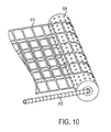
- FIG. 10 shows features of an example robotic apparatus, according to an example embodiment.
- FIGS. 11A-11D show an example sequence of placing a box on a conveyor, as may be performed by an example robotic apparatus.
- Example methods and systems are described herein. Any example embodiment or feature described herein is not necessarily to be construed as preferred or advantageous over other embodiments or features.
- the example embodiments described herein are not meant to be limiting. It will be readily understood that certain aspects of the disclosed systems and methods can be arranged and combined in a wide variety of different configurations, all of which are contemplated herein.
- Example embodiments provide for robotic apparatuses that facilitate moving objects within an environment, such as to load or unload boxes or to construct or deconstruct pallets (e.g., from a container or truck bed).
- An example apparatus may include a moveable cart, a robotic manipulator (e.g. a robotic arm) mounted to the moveable cart, and a horizontal conveyor provided on the moveable cart.
- the apparatus may also include a control system that causes the robotic manipulator to place an object on the conveyor.
- the conveyor may then provide locomotion that causes the object to move along the conveyor.
- the object may pass from the conveyor. For instance, the conveyor may pass the object to a pallet or to another conveyor.
- Certain arrangements of the robotic manipulator and the horizontal conveyor may reduce the time involved in moving each object within the environment, so as to hasten the loading or unloading of boxes, for example. Some arrangements may involve less movement of the robotic manipulator in moving each object. Further, some arrangements may allow parallelization of certain aspects of object movement. Other arrangements may reduce the time involved in positioning the apparatus to move objects. Additional or alternative advantages from the arrangements disclosed herein may be realized as well.
- One example arrangement may include a horizontal conveyor and a robotic manipulator that are each provided on a moveable cart.
- the horizontal conveyor may have a first and a second segment.
- the first segment may be mounted at a first end of the moveable cart (e.g. the front of the moveable cart).
- the moveable cart may be positioned such that the first end is adjacent to the objects to be moved.
- the robotic manipulator may then be mounted adjacent to the first segment such that, during operation, the robotic manipulator may extend over the first segment of the horizontal conveyor to pick up an object and then place the object on the first segment of the conveyor.
- Such an arrangement may involve less rotation of the robotic manipulator to place the object on the horizontal conveyor, which may shorten an amount of time involved in placing the object on the conveyor.
- first segment may provide locomotion to the object in a first direction, such as along the first end of the moveable cart.
- the second segment may be coupled to and vertically aligned with the first segment such that the locomotion of the first segment may cause the object to pass to the second segment.
- the second segment may then provide locomotion in a second direction away from the first segment, such as to the rear of the moveable cart, where the object may pass to another conveyor or be collected into a pile or a stack, for example.
- Another example arrangement may include a horizontal conveyor provided with a first and second robotic manipulator on a moveable cart.
- the first and second robotic manipulators may allow for parallelization of the function of placing objects on the horizontal conveyor. For instance, the first robotic manipulator may pick up a first box. Then, while the first robotic manipulator is placing the first box on the horizontal conveyor, the second robotic manipulator may pick up a second box. Accordingly, while the second robotic manipulator is placing the second box on the horizontal conveyor, the first robotic manipulator may pick up a third box.
- the apparatus may repeat the process to unload additional boxes.
- first and second robotic manipulators may each be mounted to a first end of the moveable cart (e.g. an end near the objects to be moved).
- the horizontal conveyor may then extend from the first end to a second end of the moveable cart (e.g. the rear of the cart) between the first and second conveyors.
- the first and second robotic manipulators may be mounted opposite one another to a member that is rotatably coupled to the moveable cart. Such an arrangement may allow the first robotic manipulator to act as a counterbalance to the second robotic manipulator.
- the first robotic manipulator may pick up a first object from a plurality of objects.
- the member may rotate (such as by 180 degrees) which may align the first robotic member with the horizontal conveyor. Since the second robotic manipulator is mounted opposite of the first robotic manipulator, the same rotation may align the second robotic manipulator with the plurality of objects.
- the second robotic manipulator may then pick up a second objects from the plurality of objects.
- the member may then rotate a second time, which may align the first robotic manipulator with the plurality of objects and the second robotic manipulator with the horizontal conveyor.
- the horizontal conveyor may be divided into a first, a second, and a third segment.
- the first, second, and third segments may be arranged into a ‘T’ configuration.
- the first segment may extend between the first and second robotic manipulators from a first end of the moveable cart to a second end (e.g. along the center of the moveable cart).
- the second and third segments may then each extend along a respective portion of the first end and provide locomotion of objects to the first segment, but in opposite directions from one another.
- the first robotic manipulator may place objects on the second segment
- the second robotic manipulator may place objects on the third segment.
- Each of the second and third segments may then convey the objects to the first segment, which may convey the objects away from the second and third segments, such as to the second end of the moveable cart (i.e. the rear of the cart).
- the conveyor may include a roller that is rotatably coupled to a frame.
- the roller may have a volume and a plurality of openings to the volume.
- a hose may connect the volume of the roller to an air pump.
- the air pump may apply a negative pressure to the roller by drawing more air out of the volume than can pass into the volume through the openings in the roller.
- the conveyor may also include a conveyor belt having openings that is wrapped around an exterior side of the roller. At least a portion of the plurality of openings in the conveyor belt may align with at least a portion of the plurality of openings of the roller so that the air pump may draw air through the aligned openings in the conveyor belt and the roller.
- the frame of the conveyor may be coupled to an actuator which may move the conveyor to bring the roller into contact with an object. Then, when the air pump applies a negative pressure to the roller, the conveyor may engage the contacted object by suction through the roller. The conveyor belt may then rotate to bring the engaged object onto the conveyor belt.
- boxes or objects may be automatically organized and placed onto pallets.
- automating the process of loading/unloading trucks and/or the process of creating pallets from objects for easier storage and transport may provide a number of industrial and business advantages.
- automating the process of loading/unloading trucks and/or the process of creating pallets may include the incorporation of one or more robotic apparatuses to move objects or perform other functions.
- a robotic apparatus can be made mobile by coupling with a wheeled base, a holonomic base (e.g., a base that can move in any direction), or rails on the ceiling, walls or floors.
- the base can be an elevated base.
- a system including one or more sensors, one or more computers, and one or more robotic arms.
- the sensors may scan an environment containing one or more objects in order to capture visual data and/or three-dimensional (3D) depth information. Data from the scans may then be integrated into a representation of larger areas in order to provide digital environment reconstruction.
- the reconstructed environment may then be used for identifying objects to pick up, determining pick positions for objects, and/or planning collision-free trajectories for the one or more robotic arms and/or a mobile base.
- boxes will refer to any object or item that can be placed onto a pallet or loaded onto or unloaded from a truck or container.
- boxes can refer to cans, drums, tires or any other “simple” shaped geometric items.
- loading and unloading can each be used to imply the other.
- palletizing refers to loading boxes onto a pallet and stacking or arranging the boxes in a way such that the boxes on the pallet can be stored or transported on the pallet.
- the terms “palletizing” and “depalletizing” can each be used to imply the other.
- a robotic manipulator may be mounted on a holonomic cart (e.g., a cart with wheels that allow the cart to move in any direction).
- FIG. 1A depicts an exemplary holonomic cart containing a robotic manipulator.
- a moveable cart 112 may include a robotic arm 102 mounted on the cart 112 .
- the robotic arm 102 may contain a gripping component 104 for gripping objects within the environment.
- the cart may contain one or more wheels 114 , which may be holonomic wheels that operate with two degrees of freedom.
- a wrap around front conveyor belt 110 may be included on the holonomic cart 112 .
- the conveyor belt may include various types of conveyor systems, such as a roller conveyor system.
- the wrap around front conveyer belt may allow the robot to not have to rotate its gripper to the left or right when unloading or loading boxes from or to a truck container or pallet.
- the robotic manipulator may be mounted on a different type of movable apparatus or may not be mounted on a movable base at all.
- the robotic manipulator may be mounted at a fixed position within a factory setting.
- one or more robotic manipulators may be mounted on rails of a truck or container. In such examples, the robotic manipulators may be used to load or unload the truck or container.
- FIG. 1B is a functional block diagram illustrating a robotic apparatus 100 , according to an example embodiment.
- the robotic apparatus 100 could include various subsystems such as a mechanical system 120 , a sensing system 130 , a control system 140 , as well as a power supply 150 .
- the robotic apparatus 100 may include more or fewer subsystems and each subsystem could include multiple elements. Further, each of the subsystems and elements of robotic apparatus 100 could be interconnected. Thus, one or more of the described functions of the robotic apparatus 100 may be divided up into additional functional or physical components, or combined into fewer functional or physical components. In some further examples, additional functional and/or physical components may be added to the examples illustrated by FIGS. 1A and 1B .
- the mechanical system 120 may include components described above with respect to FIG. 1A , including a robotic arm 102 , a gripper 104 , a conveyer belt 110 , a (movable or holonomic) cart 112 , and one or more wheels 114 .
- the mechanical system 120 may additionally include a motor 122 , which may be an electric motor powered by electrical power, or may be powered by a number of different energy sources, such as a gas-based fuel or solar power. Additionally, motor 122 may be configured to receive power from power supply 150 .
- the power supply 150 may provide power to various components of robotic apparatus 100 and could represent, for example, a rechargeable lithium-ion or lead-acid battery. In an example embodiment, one or more banks of such batteries could be configured to provide electrical power. Other power supply materials and types are also possible.
- the sensing system 130 may use one or more sensors attached to a robotic arm 102 , such as sensor 106 and sensor 108 , which may be 2D sensors and/or 3D depth sensors that sense information about the environment as the robotic arm 102 moves.
- the sensing system may determine information about the environment that can be used by control system 140 (e.g., a computer running motion planning software) to pick and move boxes efficiently.
- the control system 140 could be located on the apparatus or could be in remote communication with the apparatus.
- scans from one or more 2D or 3D sensors with fixed mounts on a mobile base such as a front navigation sensor 116 and a rear navigation sensor 118 , and one or more sensors mounted on a robotic arm, such as sensor 106 and sensor 108 , may be integrated to build up a digital model of the environment, including the sides, floor, ceiling, and/or front wall of a truck or other container.
- the control system 140 may cause the mobile base to navigate into a position for unloading or loading.
- planar surface information may be extracted from 3D sensors to model walls, floor and/or box faces. After modeling the floor, projection of objects onto the floor plane may enable segmentation of obstacles and/or target objects such as boxes.
- Floor-plane projection can also be used to model the corrugated sides of a container or truck, which may not be accurately modeled as planes.
- sidewall angles, floor plane roll and pitch, and/or distance from side walls can be used to maneuver a mobile base into a container without collisions.
- Use of extended 3D information rather than a single line scan may help make the extraction of navigation information robust.
- the side walls may have a vertical extent that is captured by the 3D sensor. Scanning systems that use a single line of depth information may be slower if they scan vertically and/or less robust because they acquire less information.
- front plane modeling can determine the distance to a next group of objects to pick in truck unloading.
- the robotic arm 102 may be equipped with a gripper 104 , such as a digital suction grid gripper.
- the gripper may include one or more suction valves that can be turned on or off either by remote sensing, or single point distance measurement and/or by detecting whether suction is achieved.
- the digital suction grid gripper may include an articulated extension.
- the potential to actuate suction grippers with rheological fluids or powders may enable extra gripping on objects with high curvatures.
- the gripper could potentially span several boxes or objects and turn on suction for some or all of the covered objects.
- the suction or adhesion devices may be a “digital” grid so that the robotic apparatus can turn on any number of the suction devices as will fit boxes sensed for grabbing.
- the system may notice a seam in the boxes (separation between adjacent boxes) such that suckers can be activated on both sides of the seam to pick up both boxes at once, thereby doubling the throughput.
- the suckers can sense after a certain amount time whether they can successfully grip a surface, after which they may automatically shut off.
- sections of the suckers can fold down to grasp the top of the boxes. For instance, grippers can initially start at full extension and then conform to the surface being gripped.
- the robotic arm can implement a wiggle movement to improve a suction grip.
- the robotic arm can wiggle a box side to side to help segment the box from its surroundings.
- the arm can wiggle upon pick up of the box to avoid jostling other objects.
- the robotic arm may employ a wiggle motion in order to make a firm seal against the object.
- the robotic arm may wiggle the object as the robotic arm is picking up the object so that the box can more gently break friction or overlap contact with other items. This may help avoid a situation where pulling the object up too directly or too quickly causes other items to be tossed into the air.
- cardboard boxes can have concave, convex or otherwise rumpled faces that make it hard for a suction device to adhere to.
- wiggling the suction device as the device makes suction contact may enable a more reliable grip on cardboard boxes and other non-planar objects.
- a few center suction devices can be turned on and the arm can wiggle back and forth as it starts to pull the box out. This may break surface adhesion with other boxes and help to start to pull the box out. Once the box is at least partially pulled out, the box may then be segmented from the other boxes more easily.
- wiggling while picking up an object in clutter may remove other objects from the picked up object, thereby preventing unwanted pick up of surrounding objects.
- segmentation of items may be necessary for successful grasping.
- a smooth surface patch may belong to two separate objects.
- manipulator interaction with the objects may be used to perturb the scene to better segment the objects from each other.
- the natural or forced movement of objects on a conveyor, on a slide, moving in a tote, and/or actively jostled within a tote may be tracked by optical flow, parallax, or time delayed views to calculate stereo depth in order to enhance object segmentation.
- one or more of the sensors used by a sensing system may be a RGBaD (RGB+active Depth) color or monochrome camera registered to a depth sensing device that uses active vision techniques such as projecting a pattern into a scene to enable depth triangulation between the camera or cameras and the known offset pattern projector.
- RGBaD RGB+active Depth
- This type of sensor data may help enable robust segmentation.
- cues such as barcodes, texture coherence, color, 3D surface properties, or printed text on the surface may also be used to identify an object and/or find its pose in order to know where and/or how to place the object (e.g., fitting the object into a fixture receptacle).
- shadow or texture differences may be employed to segment objects as well.
- Control system 140 may include at least one processor 142 (which could include at least one microprocessor) that executes instructions 144 stored in a non-transitory computer readable medium, such as the memory 146 .
- the control system 140 may also represent a plurality of computing devices that may serve to control individual components or subsystems of the robotic apparatus 100 in a distributed fashion.
- memory 146 may contain instructions 144 (e.g., program logic) executable by the processor 142 to execute various functions of robotic apparatus 100 , including those described above in connection with FIGS. 1A-1B .
- Memory 146 may contain additional instructions as well, including instructions to transmit data to, receive data from, interact with, and/or control one or more of the mechanical system 120 , the sensor system 130 , and/or the control system 140 .
- a perception guided robot may utilize a combination of perception together with planning to guide the robot arm to pick up a box and place it where it needs to go.
- FIG. 2A illustrates part of the robotic apparatus from FIG. 1A with a stack of boxes, according to an example embodiment.
- the robotic apparatus may include a robotic arm 102 with a gripping component 104 , sensors 106 and 108 , and conveyer 110 as described above.
- the robotic apparatus could be mounted on a holonomic cart as described with respect to FIG. 1A , could be mounted on a different type of movable apparatus, could be mounted on rails or tracks, or could be stationary.
- the robotic apparatus may be controlled to pick boxes from a stack of boxes 220 containing a heterogenous mix of shapes and sizes of boxes.
- a virtual environment including a model of the objects in 2D and/or 3D may be determined and used to develop a plan or strategy for picking up the boxes.
- the robot may use one or more sensors to scan an environment containing objects, as shown in FIG. 2B .
- a sensor 106 on the arm may capture sensor data about the stack of boxes 220 in order to determine shapes and/or positions of individual boxes.
- a larger picture of a 3D environment may be built up by integrating information from individual (e.g., 3D) scans. Sensors performing these scans may be placed in fixed positions, on a robotic arm, and/or in other locations. According to various embodiments, scans may be constructed and used in accordance with any or all of a number of different techniques.
- scans can be made by moving a robotic arm upon which one or more 3D sensors are mounted. Feedback from the arm position may provide pose information about where the sensor is positioned and may be used to help with the integration. Alternately, or additionally, scans may be made using one or more 2D sensors, for instance by leveraging motion and tracking keypoints in the environment. In further examples, scans may be from fixed-mount cameras that have fields of view (FOVs) covering a given field. In additional examples, scans may be visually registered to help with fine pose estimation, potentially giving better integration results.
- FOVs fields of view
- a virtual environment may be built up using a 3D volumetric or surface model to integrate information (e.g., from different sensors). This may allow the system to operate within a larger environment, such as in cases where one sensor may be insufficient to cover a large environment. Such techniques may also increase the level of detail captured, which may help the robotic apparatus perform various tasks. In particular, integrating information can yield finer detail than from a single scan alone (e.g., by bringing down noise levels). This may make possible better object detection, surface picking, or other applications.
- wide-angle environment reconstruction may be performed by sensing an environment and extracting that information into a simplified geometric model of simple mathematical 3D geometric forms (e.g., planes, cylinders, cones, hemispheres, etc).
- a simplified geometric model of simple mathematical 3D geometric forms e.g., planes, cylinders, cones, hemispheres, etc.
- such techniques may make motion planning easier and/or may make violation of the models (e.g., collisions) easier to detect.
- such techniques may allow a parametric description to extend the environment. For instance, the ground may be treated as a plane that extends behind objects that occlude it.
- planes or other mathematical surfaces in the environment may be extracted in 3D. These known “ideal” surface detections may be combined into a more accurate model of the environment. For instance, planes may be used to determine the full extents of walls (or mathematical description thereof) and other obstacles to avoid collisions and detect where objects of interest are. Also, mathematical representations of objects may be used to look for anomalies such as when person enters into an environment. Such events may violate the ideal model, which may make their detection easier.
- certain objects such as boxes may have simple planar form.
- a metal can have a geometric form of a cylinder and a tire may have a geometric form of a torus.
- Example systems may leverage this trait of certain objects in order model them and/or determine how to motion plan for the objects.
- known templates of certain shapes can be used to refine detected features of objects within the environment that appear to match a particular shape.
- 2D and 3D information may be represented at least in part via one or more facades.
- a facade may be defined as a near-planar construct containing a set of objects, represented as a depth map (e.g., a 2D map of distances as the third dimension). Examples of facades may include the wall of boxes in a truck, the top of a pallet stack containing boxes or other objects, or the top of a bin of jumbled objects.
- a facade may be constructed from boxes, for instance to plan in what order the boxes should be picked up.
- box 222 may be identified by the robotic apparatus as the next box to pick up.
- Box 222 may be identified within a facade representing a front wall of the stack of boxes 220 constructed based on sensor data collected by one or more sensors, such as sensor 106 and 108 .
- a control system may then determine that box 222 is the next box to pick, possibly based on its shape and size, its position on top of the stack of boxes 220 , and/or based on characteristics of a target container or location for the boxes.
- the robotic arm 102 may then be controlled to pick up the box 222 using gripper 104 and place the box 222 onto the conveyer belt 110 (e.g., to transport box 222 into a storage area).
- a facade may be represented as an orthographic projection of 3D surface information. This representation may allow for parsing the facade to determine interesting areas for a particular application. For example, in truck unloading, the upper left corner of the next box to pick may be determined based on a facade representation.
- an orthographic projection of integrated 3D environment may be determined to give a wide-FOV, easily-parsed representation for performing application-related tasks. One such task may be finding the corner or corners (e.g., top left) of a box to pick. Another such task may involve finding good surfaces (e.g., relatively flat and large) for picking objects out of a bin.
- a 3D model of a stack of boxes may be constructed and used as a model to help plan and track progress for loading/unloading boxes to/from a stack or pallet. Any one actual camera view of the facade may suffer from point of view occlusions and perspective distortion. Accordingly, multiple RGBD views via robot arm movements and/or different views from a cart base or fixed locations may be combine to create a single facade of the boxes to be picked.
- the 3D model may be used for collision avoidance.
- planning a collision-free trajectory may involve determining the 3D location of objects and surfaces in the environment.
- a trajectory optimizer may make use of the 3D information provided by environment reconstruction to optimize paths in the presence of obstacles.
- the optimizer may work in real time and may accept many kinds of constraints. As an example of such a constraint, the optimizer may attempt to keep the end effector level throughout the trajectory.
- an environment may be captured as a mesh or set of 3D points.
- a robot arm may be represented as a convex hull of plane segments for quick collision checking Constant or frequent updating of the environment may allow the robot arm to quickly respond to changes.
- an optimizer may perform frequent continuous collision checking throughout its path.
- An optimizer may accept arbitrary constraints in the form of costs, such as to keep a certain distance away from objects or to approach a goal position from a given angle. Additionally, an optimizer may avoid robot fault conditions by working in joint space, keeping track of windup and choosing goal positions from among multiple inverse kinematics solutions.
- One strategy for motion planning may involve looking ahead several moves to see if the chosen goal joint position will be acceptable for the next move.
- path constraints such as collision avoidance for robotic arms, cameras, cables, and/or other components
- path constraints may be put in a constraint based planning solver and solved for to yield a best path to move the arm for perception.
- the solver may determine a best path for picking up, moving, and placing an object.
- 3D and/or visual sensors may be calibrated to determine their pose with respect to the workspace.
- the calibration may determine their fixed pose in the workspace.
- calibration may determine the offset pose of the sensor from the arm link to which it is attached.
- calibration techniques may allow for the calibration of an arbitrary number of sensors in the workspace. Calibration may involve determining some or all of a variety of parameters and coefficients. For example, calibration may solve for one or more intrinsic parameters such as focal length and image center. As another example, calibration may determine one or more distortion coefficients such as models of radial and tangential distortion. As yet another example, calibration may solve for one or more extrinsic parameters, where the object is in a scene relative to a pattern or other sensors that identified the same pattern in a scene.
- calibration may be performed at least in part by using a calibration pattern, which may be a known set of features in 2D or 3D. For instance, a known pattern of dots may be used, where the distance between each dot and the other dots is known. Calibration may be performed at least in part by collecting multiple different views of an object. In further examples, capturing multiple views of a calibration pattern in different positions may allow for (1) calibration of the one or more coefficients of the camera and/or (2) knowledge of where the camera is relative to the coordinate system established by where the calibration pattern was fixed. In particular embodiments, a camera in the scene may identify a calibration pattern on the robot arm while a camera on the arm identifies a calibration pattern in the scene simultaneously.
- calibration may involve a camera fixed in a scene.
- a calibration pattern may be placed on a robotic arm.
- the robotic arm may be configured to move through the scene as multiple views of the calibration pattern on the robotic arm are collected. This may help to calibrate the camera and/or be useful for relating the coordinate system of the camera to that of the robot. Further, the relation of each apparatus to the other can be determined by each apparatus as the robotic arm moves.
- calibration may involve a camera located on a robotic arm.
- a calibration pattern may be mounted on a wall or table. Then, the camera may be moved around, collecting multiple views of the calibration pattern from different robot or robotic arm positions. When different 3D or 2D views (e.g., 2, 20, 200) are collected, these views can be used to solve for the calibration relationships.
- the system can determine where it is relative to the coordinate system set based on the location of the calibration pattern in the scene.
- both the calibration pattern and the camera may be movable.
- the calibration pattern may be located on a conveyor belt where the robotic arm may be configured to place boxes. After calibration, the system may determine where the camera was relative to that spot on the conveyor belt.
- nonlinear optimization may be performed in a two-stage process for robust estimation of 3D sensor calibration.
- an initialization may be derived from the relative pose offsets of the target and the sensors.
- a batch bundle adjustment may be used to find the optimal pose of the cameras together with the target points.
- Calibration can be extended to the estimation of robot parameters such as joint lengths and joint angle offsets.
- known, precise, robot motion of the camera over a calibration pattern, or a calibration pattern over a camera may be used to improve calibration results. For instance, information about precisely how the camera moves may be used to obtain more accurate camera calibration. That is, if the camera is moved 50 mm right, the corresponding (perspective projection) amount of movement from the calibration object may be detected. This information may be used to jointly or separately optimize the calibration and tracking parameters.
- a robot can look at its ongoing calibration and move in such a way as to maximize information for better calibration. For example, it can detect that some view areas have not been seen and go to those views.
- a system for the practical manipulation of heterogeneous, categorical items generally from a cluttered collection area to a defined bin.
- the pick location containing the items may not be sensitive to precise object orientation(s) and items may be mixed together.
- the place location for the items may or may not be sensitive to object orientation.
- the pick-and-place regions may be defined as 3D regions acceptable for picking or placing an object, with some tolerance.
- the pick-and-place region may be highly cluttered with similar and/or disparate objects.
- the items may come from or be put into a fixture, such as metal or plastic snaps that hold the sorted item in a particular orientation.
- environment modeling of both the pick-and-place location may be used for intelligent grasp location and motion, as well as event reporting (e.g., when a place region is full or a pick region is empty).
- object bounding volumes may be computed and/or distinguishing features of objects may be found (such as textures, colors, barcodes or OCR).
- objects may be sorted into an assigned destination location by matching against a database of location assignments indexed by object type or object ID. For instance, an object's locations may be derived from reading a barcode, considering the size of the object, and/or by recognizing a particular kind of object.
- a plan for a robotic apparatus may be determined in order to achieve certain configurations of the objects within a target location for the objects.
- the goals for loading/unloading or constructing/deconstructing pallets may be to achieve: 1) a dense packing with minimal air gaps in between boxes, and/or 2) a stable packing that won't easily collapse.
- stability may require that, in general, heavy objects are on the bottom, and light objects are on top.
- pallets may be created in order to avoid non-interlaced column stacks, column leans, or other characteristics of a bad stack.
- the pallet or truck/container may be loaded such that work by human operators in subsequent unloading processes is minimized.
- items may be placed in last in, first out order such that, upon unpacking, the items needed first are on top, the items needed second are one layer down and so on.
- the loading of pallets may be independent of how items flow toward the packing cells.
- the system can handle packages sent in random order or in an order known in advance.
- systems may adapt to changes in the flow of items on the fly.
- one or more boxes may be recorded and buffered by holding the boxes in a temporary storage area where their order can be changed along the way.
- a 2D simulator and/or a 3D simulator may be utilized for truck or container loading/unloading or for pallet loading/unloading.
- the state of a stack of boxes may be captured in the physical world and input into the simulator.
- a variable size queue of boxes from one to all the boxes may be used by a simulator for finding a next box to pick. For example, a queue of 2 boxes or 4 boxes or 10 boxes may be considered by a simulator.
- the simulator may search over the boxes in the queue to find the best box placement by heuristic algorithms and/or by brute force or multi-resolution search.
- the system may increment with increasingly fine placement of boxes around the best sites found in the previously coarser level.
- a physics planner may be used for motion planning in order to move the box efficiently to the determined locations.
- the physical and simulated stacks may be continuously monitored for quality of the stack (e.g., density, stability, and/or order placement). In some examples, the process may be repeated until all the boxes have been placed or the target container can no longer fit in another box.
- FIG. 3 shows a robotic apparatus 300 according to an example embodiment.
- the robotic apparatus includes a moveable cart 302 having holonomic wheels. While the moveable cart is shown having holonomic wheels by way of example, the moveable cart 302 may have other types of wheels. For example, the moveable cart 302 may have wheels arranged to move the moveable cart 302 on rails.
- a robotic arm 304 is mounted to the moveable cart 302 at a first end of the moveable cart 302 (which may be considered the front side of the moveable cart 302 ). While a robotic arm is shown by way of example, the robotic apparatus 300 may include any type of robotic manipulator that is suitable for placing objects onto a conveyor.
- the robotic arm 304 has a first end that is mounted to the moveable cart and a second end that has an end effector 306 (i.e. a grasper).
- a horizontal conveyor 308 is provided on the moveable cart 302 in a wrap-around arrangement.
- the horizontal conveyor 308 includes a frame and a plurality of rollers rotatably coupled to the frame, as shown.
- a belt may drive the plurality of rollers which may cause the rollers to rotate and thereby provide locomotion.
- Such an arrangement may be referred to a roller-type conveyor. While a roller-type conveyor is shown by way of example, an example apparatus may include other types of conveyors, such as a belt-type conveyor.
- a horizontal conveyor may be arranged into a wrap-around configuration.
- a wrap-around arrangement of the horizontal conveyor 308 is formed by a first segment 310 and a second segment 312 that are orthogonal to one another.
- the first segment 310 extends along the front side near the robotic arm 304 .
- This arrangement may reduce the amount of rotation of the robotic arm 304 involved in placing objects on the horizontal conveyor 308 because the robotic arm 304 may place objects at any point along the length of the first segment 310 . For example, if the robotic arm 304 picks up an object near the front right corner of the moveable cart, the robotic arm 304 may then place the object on the right side of the first segment 310 . Alternatively, in some circumstances, the robotic arm 304 may place an object on the second segment 312 , such as if the object is near the far left side of the moveable cart 302 .
- a horizontal conveyor may be arranged into a “Y” configuration.
- a “Y” configuration may include a first segment that extends along a portion of a left side of the moveable cart and provides locomotion towards the rear of the cart.
- the “Y” configuration may also include a third segment that extends along a portion of a right side of the moveable cart and provides locomotion in parallel with the locomotion provided by the portion of the first segment.
- the first and third segments may each also extend towards and converge at a second segment.
- the second segment may then provide locomotion from the first and third conveyors towards the rear of the moveable cart.
- Such an arrangement may allow the robotic manipulator to place objects on the horizontal conveyor using less movement.
- the robotic manipulator may place objects to the right of the moveable cart on the third segment and place objects to the left of the moveable cart on the first segment. Then, in either case, locomotion provided by the first or third segment may move the object to the second segment.
- each of the first segment 310 and the second segment 312 provide locomotion.
- the first segment 310 may provide locomotion in a first direction, such as toward the second segment 312 , as shown.
- the second segment 312 is coupled to and vertically aligned with the first segment 310 (i.e. at the same height), also as shown. This arrangement may allow continuous locomotion of objects from the first segment 310 to the second segment 312 .
- the second segment 312 provides locomotion away from the first segment 310 (i.e. toward the rear of the cart 302 ). This arrangement may facilitate integration with a pre-existing unloading system, as commonly used in warehouses and factories.
- a particular unloading system may include a moveable conveyor that may facilitate moving objects from a loading dock to storage areas within a warehouse.
- the robotic apparatus 300 may improve efficiency in transporting objects from the truck to a storage area within the warehouse (i.e. unloading the truck).
- the second segment 312 may lead to another apparatus for palletizing the objects.
- unloading system are possible.
- Robotic apparatus 300 also includes a control system 314 configured to receive sensor data indicative of an environment containing a plurality of objects and then cause the robotic manipulator to place an object from the plurality of objects on the horizontal conveyor.
- the sensor data may include sensor scans of portions of the environment using sensors located on the robotic arm 304 , on the moveable cart 302 , and/or at other fixed or movable locations within the environment.
- the robotic arm 304 may move through the environment in order to allow a camera (e.g., a 3D depth sensor) to scan a group of object such as a stack of boxes as illustrated and described above with respect to FIG. 2B .
- a camera e.g., a 3D depth sensor
- the robotic arm 304 may be programmed to move along certain motion paths (e.g., arcs or zigzags) in order to collect sensor data using one or more sensors mounted on the robotic arm.
- scans from multiple sensors may be combined in order to create a single virtual representation of the environment.
- the process of receiving sensor data from the one or more sensors and determining a virtual representation may be performed by the control system 314 of the robotic device 300 and/or by a remote control system.
- robotic apparatus 300 may include sensor(s) 318 .
- Sensor(s) 318 may be attached the robotic arm 304 as shown. Further, sensor(s) 318 may be communicatively coupled to the control system 314 and configured to send data representing the environment to the control system 314 .
- the robotic apparatus 300 may further include an actuator 316 , such as an electric, hydraulic, or pneumatic motor, that is coupled between the moveable cart 302 and the first segment 310 .
- the actuator 316 may be coupled to the frame of the conveyor.
- the actuator 316 may be configured to extend the first segment 310 away from the front of the moveable cart 302 and also to retract the first segment 310 back toward the moveable cart 302 . Such a configuration may reduce the amount of movement involved in the robotic arm 304 placing objects on the first segment 310 .
- the first segment 310 may extend away from the moveable cart to reduce the distance that the end effector 306 moves back toward the moveable cart 302 to place the object on the first segment 312 .
- robotic apparatus 300 may include a drive system 320 coupled to the moveable cart 302 .
- the drive system 320 may include, for example, one or more motors configured to drive one or more wheels of the moveable cart 302 (e.g. the holonomic wheels shown in FIG. 3 ).
- Control system 314 may be configured to cause the drive system to move the cart 302 within the environment. For instance, control system 314 may cause the drive system 320 to move the moveable cart 302 to objects such that the robotic arm 304 is within range of picking up the objects.
- Robotic manipulators such as the robotic arm 304 in FIG. 3
- the range may be proportional to the distance between the first end and the second end (i.e. a “reach” of the robotic arm).
- a robotic apparatus may include additional features to extend the range of the robotic manipulator.
- a robotic apparatus may include a moveable base arranged to move horizontally relative to the moveable cart.
- a robotic apparatus may include a vertical support arranged such that the robotic manipulator may move up and down the vertical support and thereby extend its range.
- the robotic apparatus may include an anchor.
- the anchor may include, for example, one or more skids.
- One or more actuators may be coupled between the moveable cart and the anchor.
- a control system may cause the actuator to extend the skid downwards to contact the ground.
- Such an extension of the anchor may increase a coefficient of friction between the ground and the moveable cart.
- the extension may cause one or more of the wheels of the moveable cart to lift away from the ground.
- the control system may be configured to cause the actuator to extend the anchor downwards to contact the ground while the robotic manipulator is placing an object on the conveyor. Then, when the object is on the conveyor, the control system may be configured to cause the actuator to retract the anchor away from the ground.
- Such a configuration may prevent substantial movement of the moveable cart relative to the ground that may be result from a shifting of a center of gravity of the moveable cart that may be caused by movement of the robotic manipulator.
- the moveable cart may be divided along a length of the moveable cart into a first section and a second section.
- the first section may be pivotably coupled to the second section.
- the first section and the second section may each have one or more respective wheels.
- the first section may have two wheels coupled in parallel towards the front of the holonomic cart and the second section may have two wheels coupled in parallel towards the rear of the cart.
- this arrangement may allow the wheels of the moveable cart to maintain contact with the ground that is relatively more consistent. For instance, the ground may be uneven. Then, when the moveable cart moves across the uneven ground, the second section may pivot relative to the first section. In addition, such an arrangement may assist in distributing weight relatively more evenly across the moveable cart.
- FIG. 4 shows a robotic apparatus 400 according to an example embodiment.
- Robotic apparatus 400 includes moveable cart 302 , robotic arm 304 , horizontal conveyor 308 , and control system 314 .
- Robotic arm 302 is coupled to a moveable base 402 .
- Moveable base 402 is provided on the top surface of moveable cart 302 .
- An actuator 404 is coupled between the moveable base 402 and the moveable cart 302 .
- Control system 314 may cause actuator 404 to move the moveable base 402 horizontally relative to the moveable cart 302 .
- actuator 404 may slide the moveable base 402 backwards and forwards relative to the moveable cart 302 , as shown.
- actuator 404 may be configured to move the moveable base 402 backwards, forwards, to the left, and to the right relative to the moveable cart. This arrangement may further extend the effective range of the robotic arm 302 in additional directions.
- FIG. 5 shows a robotic apparatus 500 according to an example embodiment.
- Robotic apparatus 500 includes moveable cart 302 , robotic arm 304 , horizontal conveyor 308 , and control system 314 .
- Robotic arm 302 is coupled to a vertical support 502 .
- the vertical support 502 is provided on a top surface of moveable cart 302 .
- vertical support 502 may be a pole, as shown.
- An actuator 504 is coupled between the vertical support 502 and the moveable cart 302 .
- Control system 314 may cause actuator 504 to move the robotic arm 304 vertically relative to the moveable cart 302 .
- actuator 504 may slide the robotic arm 304 up and down along the vertical support 502 .
- This arrangement may extend an effective range of the robotic arm 304 (where the effective range is the range of the robotic arm 304 combined with a range of movement along the vertical support 502 ) by allowing the robotic arm 304 to reach higher objects.
- FIG. 6 shows a robotic apparatus 600 according to an example embodiment.
- the robotic apparatus 600 includes a moveable cart 602 having holonomic wheels.
- a first robotic arm 604 is mounted to the moveable cart 602 at a first end of the moveable cart 602 (which may be considered the front-left corner of the moveable cart 602 ).
- a second robotic arm 606 is mounted to the moveable cart 602 at the first end of the moveable cart 602 opposite the first robotic arm 604 (which may be considered the front-right corner of the moveable cart 602 ).
- the first robotic arm 604 and the second robotic arm 606 each have a first end that is mounted to the moveable cart and a second end that has an end effector.
- This arrangement may allow for a relatively larger effective range to the left and right of the moveable cart 602 in which objects may be picked up by either the first robotic arm 604 or the second robotic arm 606 .
- This arrangement may also reduce the amount of movement involved placing objects on a conveyor.
- the second robotic arm 606 may pick up objects that are located toward the front-right corner of the moveable cart 602 which may involve less movement relative to a robotic arm that is mounted in the center or on the left side of the moveable cart 602 picking up the same objects.
- a horizontal conveyor 608 is provided on the moveable cart 602 .
- the horizontal conveyor 608 includes a frame and a plurality of rollers rotatably coupled to the frame, as shown.
- the horizontal conveyor 608 extends from the first end of the moveable cart 602 to a second end (i.e. a length of the moveable cart 602 ).
- the horizontal conveyor 608 may extend for a portion of the length of the moveable cart 602 .
- the horizontal conveyor 608 may extend beyond the length of the moveable cart 602 .
- the horizontal conveyor 608 is provided between the first robotic arm 604 and the second robotic arm 608 . This arrangement may allow for both the first robotic arm 604 and the second robotic arm 606 to place objects on the horizontal conveyor.
- the horizontal conveyor 608 provides locomotion in a first direction (i.e. toward the rear of the moveable cart 602 ). By providing locomotion toward the rear of the cart, this arrangement may facilitate integration with pre-existing unloading systems that may be commonly used in warehouses and factories, among other locations, as noted above.
- Robotic apparatus 600 also includes a control system 610 configured to receive sensor data indicative of an environment containing a plurality of objects.
- the sensor data may include sensor scans of portions of the environment.
- the sensors may located on the first robotic arm 604 , the second robotic arm 606 , on the moveable cart 602 , and/or at other fixed or movable locations within the environment.
- the process of receiving sensor data from the one or more sensors may be performed by the control system 610 of the robotic device 600 and/or by a remote control system.
- Control system 610 is also configured to cause the first robotic manipulator to place an first object from the plurality of objects on the conveyor, and to cause the second robotic manipulator to place an second object from the plurality of objects on the conveyor.
- the first robotic arm 604 and the second robotic arm 606 may alternate actions involved in placing objects on the horizontal conveyor 608 , which may improve efficiency in some circumstances.
- the control system 610 may cause the second robotic arm 606 to pick up the second object while the first robotic manipulator 604 is placing the first object on the horizontal conveyor 608 ; and then cause the first robotic manipulator 604 to pick up a third object while the first robotic manipulator 604 is placing the second object on the horizontal conveyor 608 .
- the first robotic arm 604 and the second robotic arm 606 may continue to alternate actions to pick up additional objects. Such alternating of object placement may improve efficiency of object movement, such as box unloading, for example.
- robotic apparatus 600 may also include a drive system 612 .
- the control system 610 may be configured to cause the drive system 612 to move the moveable cart 602 based on sensor data.
- the control system 610 may be configured to receive data indicating that the first object is out of the range of the first robotic arm 604 , receive data, for one or more objects in the environment, indicating one or more respective distances to the one or more objects, determine a path to the first object based on the data indicating one or more respective distances to the one or more objects, and cause the holonomic drive system 612 to move the moveable cart 602 toward the first object based on the determined path.
- FIG. 7 shows a robotic apparatus 700 according to an example embodiment.
- Robotic apparatus 700 includes moveable cart 602 , first robotic arm 604 , second robotic arm 606 , control system 610 , and a horizontal conveyor 702 .
- First robotic arm 604 and second robotic arm 606 are mounted to moveable cart 602 opposite one another at one end (i.e. the front) of the moveable cart 602 , as shown.
- Horizontal conveyor 702 includes a first segment 704 , a second segment 706 , and a third segment 708 which are arranged into a “T” configuration.
- the horizontal conveyor 702 includes a frame and a plurality of rollers rotatably coupled to the frame, as shown.
- the first segment 704 extends along a top surface of the moveable cart 602 from a first side of the moveable cart 602 to a second side (i.e. a length of the moveable cart 602 ). Within examples, the first segment may extend further or less than the length of the moveable cart 602 .
- the first segment 704 is provided between the first robotic arm 604 and the second robotic arm 606 .
- first segment 704 is shown as centered on the surface of the moveable cart 602 , other arrangements are possible as well. For instance, the first segment 704 may be offset to the right or left. Alternatively, the first segment 704 may be elevated above the surface of the moveable cart 602 by one or more vertical supports. The first segment 704 provides locomotion in a first direction (i.e. toward the rear of the moveable cart 602 ).
- the second segment 706 and the third segment 708 each extend along a portion of the first side of the moveable cart 602 . Further, the second segment 706 and the third segment 708 are each coupled to and vertically aligned with the first segment 704 such that objects on either the second segment 706 or the third segment 708 may move to the first segment 704 . As shown, the second segment 706 provides locomotion to the first segment 704 and the third segment 708 provides locomotion to the first segment 704 in a direction opposite the locomotion of the second segment 706 .
- FIG. 8 shows a robotic apparatus 800 according to an example embodiment.
- Robotic apparatus 800 includes moveable cart 602 , first robotic arm 604 , second robotic arm 606 , control system 610 , and a horizontal conveyor 802 .
- the first robotic arm 604 and the second robotic arm 606 are mounted opposite one another to a member 804 that is rotatably coupled to a surface of the moveable cart 602 , as shown.
- the member 804 may be a rigid structure capable of supporting the first robotic arm 604 and the second robotic arm 606 .
- Such an arrangement of the first robotic arm 604 and the second robotic arm 606 may allow the first robotic arm 604 to fully or partially counterbalance the second robotic arm 606 and vice versa.
- the first robotic arm 604 may pick up a first object from a plurality of objects. Then, the member 804 may rotate (such as by 180 degrees) to align the first robotic member with the horizontal conveyor 802 . Then, since the second robotic arm 606 is mounted opposite of the first robotic arm 604 , the rotation may align the second robotic arm 604 with the plurality of objects. The second robotic arm 606 may then pick up a second object from the plurality of objects. The member 804 may rotate a second time, which may align the first robotic arm 604 with the plurality of objects and the second robotic arm 606 with the horizontal conveyor 802 .
- the control system 610 may be configured to cause one or more rotations of the member 804 . For instance, the control system 610 may be configured to cause the 180 degree rotation noted above.
- one or more additional robotic arms may be distributed on the member with the first and second robotic arms. For instance, three robotic arms may be spaced 120 degrees apart from one another. Such embodiments may include one or more additional conveyors that may allow for parallelization of functions.
- robotic apparatus 800 may be configured to orient boxes on a large side (e.g. the 24′′ ⁇ 6′′ side of the example 24′′ by 6′′ by 6′′ box above).
- a large side e.g. the 24′′ ⁇ 6′′ side of the example 24′′ by 6′′ by 6′′ box above.
- Such a configuration may include a first moveable member 806 and a second moveable member 808 arranged above the horizontal conveyor 802 .
- the first moveable member 806 and the second moveable member 808 may be coupled to one or more actuators 810 .
- the control system 610 may be configured to cause the one or more actuators 810 to move the first moveable member 806 and the second moveable member 808 over the horizontal conveyor 802 perpendicular to the direction of locomotion of the horizontal conveyor 810 (or a part thereof that is under the moveable members).
- the configuration may also include a sensor 812 , such as a depth sensor, that is arranged to generate data indicative of one or more dimensions of objects that are engaged by a robotic manipulator of the apparatus.
- the control system 610 may determine that an object engaged by the robotic manipulator has a vertical dimension that is greater than a threshold (e.g. 18 ′′) based on data from the sensor. Based on such a determination, the control system 610 may cause the one or more actuators 810 to move the first moveable member 806 and the second moveable member 808 over the horizontal conveyor 802 . Then, when the object is placed on the horizontal conveyor 802 , locomotion provided by the horizontal conveyor 802 may cause the object to contact the first moveable member 806 .
- a threshold e.g. 18 ′′
- Such contact may cause the object to tip over in a direction opposite the direction of locomotion of the horizontal conveyor 802 .
- the object may then contact the second moveable member 808 before contacting the horizontal conveyor 802 , which may cause the object to contact the horizontal conveyor 802 with relatively less force.
- the control system 610 may also be configured to cause the one or more actuators 810 to move the first moveable member 806 and the second moveable member 808 such that the first moveable member 806 and the second moveable member 808 do not intersect objects moving along the horizontal conveyor 802 .
- FIG. 9 is a functional block diagram illustrating a robotic apparatus 900 , according to an example embodiment.
- Robotic apparatus 900 includes a conveyor 904 provided on a moveable cart 902 .
- Conveyor 904 may engage objects by suction and then rotate to place the objects on the conveyor 904 .
- the moveable cart 902 may have one or more wheels 922 coupled to a drive system 924 .
- Conveyor 904 provided on the moveable cart 902 may include various components that create suction through openings in a roller 906 .
- the robotic apparatus 900 may include an air pump 916 that is coupled to a volume of the roller 906 via a hose 918 .
- the air pump 916 is configured to draw air through the openings in the roller 906 , through the volume of the roller 906 , and out of the hose 918 to create suction at the openings in the roller 906 .
- the hose 918 may be coupled to the roller 906 at one end of the roller 906 , such that the coupling of the hose 918 to the roller 906 forms a portion of the coupling of the roller 906 to the frame 908 . This arrangement may allow rotation of the roller 906 while the hose 918 is coupled to the roller 906 .
- the roller 906 may be rotatably coupled to a frame 908 at each end of the roller 906 .
- the conveyor 904 may also include one or more additional rollers 914 rotatably coupled to the frame 908 .
- One end of the frame 908 may be coupled to the moveable cart 902 .
- the roller 906 may be coupled to an end of the frame 908 opposite the end of the frame 908 that is coupled to the moveable cart 902 such that the roller 906 is positioned at a distance from the moveable cart (i.e. a length of the frame or a portion thereof). This arrangement may facilitate engaging objects by suction.
- Robotic apparatus 900 may also include a conveyor belt 910 that is wrapped around the roller 906 .
- the conveyor belt 910 may also be wrapped around the one or more additional rollers 914 .
- a particular roller of the one or more additional rollers 914 may be coupled to a motor 912 that causes the particular roller to rotate and thereby turn the conveyor belt 910 .
- the conveyor belt 910 may have openings that align with openings in the roller 906 such that air may be drawn in by the air pump 916 through the openings in both the conveyor belt 910 and the roller 906 .
- Robotic apparatus 900 may also include one or more actuators 920 coupled between the moveable cart 902 and the frame 908 .
- the actuators 920 may tilt the conveyor 904 up and down to allow the conveyor 904 to contact with objects that are at varying heights from the ground.
- the one or more actuators 920 may be arranged to rotate the conveyor 902 to allow the conveyor 904 to contact objects that are toward either side of the moveable cart 902 .
- Other arrangements are possible as well.
- Robotic apparatus 900 may also include a control system 926 that may include a processor 926 , instructions 928 , and memory 930 .
- the control system 926 may be configured to perform functions. For instance, the control system 926 may receive sensor data indicating an environment containing a plurality of objects. The control system 926 may then cause the actuators 920 to bring the conveyor belt 910 in contact with an object from the plurality of objects. After the conveyor belt 910 is in contact with the object, the control system 926 may cause the air pump 916 to apply a negative pressure to the volume of the roller 906 to engage the object by suction, and then cause the conveyor belt 910 to rotate around the roller 906 toward the moveable cart 902 to place the object on the conveyor belt 910 .
- the control system 926 may cause robotic apparatus 900 to pull the object toward the moveable cart 902 which may in turn expose an edge of the object.
- the control system 926 may be further configured to cause the actuators 9120 to tilt the frame 908 of the conveyor 904 upwards. When the object is stacked on another object in a stack, such an upwards tilt may pull the object which may expose an edge of the object relative to other object.
- the control system 926 may then cause the actuators 920 to move the conveyor belt 910 under the exposed edge.
- the moveable cart 902 may move toward the stack which may position the conveyor belt 910 under the exposed edge.
- control system 926 may receive sensor data indicating that the object is placed on the conveyor 904 (i.e. the conveyor belt 910 ) and then cause the air pump 916 to release the negative pressure of the volume of the roller 906 . Once the object is on the conveyor 906 , engagement of the object by suction may no longer be needed or desired, so the control system 924 may disengage the air pump 916 , which may release the negative pressure in the roller 906 .
- the sensor data may be received from a belt scale, for example, that may be configured to weigh objects on the conveyor belt 912 .
- FIG. 10 shows a portion of robotic system 900 that includes roller 906 and conveyor belt 910 of conveyor 904 .
- Roller 906 has a plurality of holes into its volume, as shown. Further, conveyor belt 910 is wrapped around roller 910 .
- Hose 918 is connected to the volume of roller 906 .
- FIGS. 11A-11D shows a sequence of functions performed by the robotic apparatus 900 to place a box 1100 on the conveyor 904 .
- the control system 926 causes the conveyor belt 910 to contact a box 1100 in a stack of boxes.
- the control system 916 causes the air pump 916 to create a negative pressure in the roller 906 , which may engage the box 1100 by suction.
- the robotic apparatus 900 pulls the box 1100 to expose an edge of the box 1100 from the stack of boxes.
- the conveyor 904 is then moved under the exposed edge of the box 1100 and the conveyor belt 910 is rotated to place the box 1100 on the conveyor 904 .
- Some objects may be relatively less stable in certain orientations. For instance, a box that measures 24′′ by 6′′ by 6′′ may be relatively less stable when placed on a side that measures 6′′ by 6′′ (i.e. a small side) than if places on a side that measures 24′′ by 6′′ (i.e. a large side) because the box has a relatively higher center of gravity in that orientation. Further, when such a box is placed on a conveyor with the small side down, locomotion provided by the conveyor may exert a force on the box that may cause the box to tip over. In some circumstances, tipping over may cause the box may fall off of the conveyor.
- a control system may be configured to cause a robotic manipulator to place such boxes on a large side (e.g. the 24′′ by 6′′ side), such a configuration may slow placing objects on the conveyor because the configuration may involve additional movement (e.g. rotation).
- objects near the box may create difficulty in picking up the box in an orientation that facilitates placing the box on the conveyor in a certain orientation.
- control systems described herein can be implemented as special-function and/or configured general-function hardware modules, portions of program code executed by a processor for achieving specific logical functions, determinations, and/or steps described in connection with the control systems described herein.
- program code can be stored on any type of computer-readable medium, for example, such as a storage device including a disk or hard drive.
- control systems described herein may represent circuitry that is wired to perform the specific logical functions in the process. Unless specifically indicated, functions may be executed out of order from that shown or discussed, including substantially concurrent execution of separately described functions, or even in reverse order in some examples, depending on the functionality involved, so long as the overall functionality of the described method is maintained.
- a function that represents a processing of information may correspond to circuitry that can be configured to perform the specific logical functions of a herein-described method or technique.
- a block that represents a processing of information may correspond to a module, a segment, or a portion of program code (including related data).
- the program code may include one or more instructions executable by a processor for implementing specific logical functions or actions in the method or technique.
- the program code and/or related data may be stored on any type of computer readable medium such as a storage device including a disk or hard drive or other storage medium.
- the computer readable medium may also include non-transitory computer readable media such as computer-readable media that stores data for short periods of time like register memory, processor cache, and random access memory (RAM).
- the computer readable media may also include non-transitory computer readable media that stores program code and/or data for longer periods of time, such as secondary or persistent long term storage, like read only memory (ROM), optical or magnetic disks, compact-disc read only memory (CD-ROM), for example.
- the computer readable media may also be any other volatile or non-volatile storage systems.
- a computer readable medium may be considered a computer readable storage medium, for example, or a tangible storage device.
- a block that represents one or more information transmissions may correspond to information transmissions between software and/or hardware modules in the same physical device. However, other information transmissions may be between software modules and/or hardware modules in different physical devices.
Abstract
Description
Claims (23)
Priority Applications (2)
| Application Number | Priority Date | Filing Date | Title |
|---|---|---|---|
| US14/213,300 US9393686B1 (en) | 2013-03-15 | 2014-03-14 | Moveable apparatuses having robotic manipulators and conveyors to facilitate object movement |
| US15/182,881 US9492924B2 (en) | 2013-03-15 | 2016-06-15 | Moveable apparatuses having robotic manipulators and conveyors to facilitate object movement |
Applications Claiming Priority (5)
| Application Number | Priority Date | Filing Date | Title |
|---|---|---|---|
| US201361798505P | 2013-03-15 | 2013-03-15 | |
| US201361793151P | 2013-03-15 | 2013-03-15 | |
| US201361798425P | 2013-03-15 | 2013-03-15 | |
| US201361798564P | 2013-03-15 | 2013-03-15 | |
| US14/213,300 US9393686B1 (en) | 2013-03-15 | 2014-03-14 | Moveable apparatuses having robotic manipulators and conveyors to facilitate object movement |
Related Child Applications (1)
| Application Number | Title | Priority Date | Filing Date |
|---|---|---|---|
| US15/182,881 Continuation US9492924B2 (en) | 2013-03-15 | 2016-06-15 | Moveable apparatuses having robotic manipulators and conveyors to facilitate object movement |
Publications (1)
| Publication Number | Publication Date |
|---|---|
| US9393686B1 true US9393686B1 (en) | 2016-07-19 |
Family
ID=53763119
Family Applications (16)
| Application Number | Title | Priority Date | Filing Date |
|---|---|---|---|
| US14/213,089 Active US9333649B1 (en) | 2013-03-15 | 2014-03-14 | Object pickup strategies for a robotic device |
| US14/212,328 Active US9102055B1 (en) | 2013-03-15 | 2014-03-14 | Detection and reconstruction of an environment to facilitate robotic interaction with the environment |
| US14/212,514 Active US9233470B1 (en) | 2013-03-15 | 2014-03-14 | Determining a virtual representation of an environment by projecting texture patterns |
| US14/213,300 Active 2034-10-15 US9393686B1 (en) | 2013-03-15 | 2014-03-14 | Moveable apparatuses having robotic manipulators and conveyors to facilitate object movement |
| US14/213,191 Active US9227323B1 (en) | 2013-03-15 | 2014-03-14 | Methods and systems for recognizing machine-readable information on three-dimensional objects |
| US14/212,994 Active US9238304B1 (en) | 2013-03-15 | 2014-03-14 | Continuous updating of plan for robotic object manipulation based on received sensor data |
| US14/793,246 Active 2034-05-08 US9630320B1 (en) | 2013-03-15 | 2015-07-07 | Detection and reconstruction of an environment to facilitate robotic interaction with the environment |
| US14/950,828 Active US9707682B1 (en) | 2013-03-15 | 2015-11-24 | Methods and systems for recognizing machine-readable information on three-dimensional objects |
| US14/961,607 Active 2034-05-19 US9862093B2 (en) | 2013-03-15 | 2015-12-07 | Determining a virtual representation of an environment by projecting texture patterns |
| US14/964,724 Active US9630321B2 (en) | 2013-03-15 | 2015-12-10 | Continuous updating of plan for robotic object manipulation based on received sensor data |
| US15/093,118 Active US9987746B2 (en) | 2013-03-15 | 2016-04-07 | Object pickup strategies for a robotic device |
| US15/182,881 Active US9492924B2 (en) | 2013-03-15 | 2016-06-15 | Moveable apparatuses having robotic manipulators and conveyors to facilitate object movement |
| US15/827,321 Active 2035-07-18 US10967506B2 (en) | 2013-03-15 | 2017-11-30 | Determining a virtual representation of an environment by projecting texture patterns |
| US15/968,323 Active US10518410B2 (en) | 2013-03-15 | 2018-05-01 | Object pickup strategies for a robotic device |
| US16/687,106 Active 2034-07-16 US11383380B2 (en) | 2013-03-15 | 2019-11-18 | Object pickup strategies for a robotic device |
| US17/196,660 Pending US20210187736A1 (en) | 2013-03-15 | 2021-03-09 | Determining a Virtual Representation of an Environment By Projecting Texture Patterns |
Family Applications Before (3)
| Application Number | Title | Priority Date | Filing Date |
|---|---|---|---|
| US14/213,089 Active US9333649B1 (en) | 2013-03-15 | 2014-03-14 | Object pickup strategies for a robotic device |
| US14/212,328 Active US9102055B1 (en) | 2013-03-15 | 2014-03-14 | Detection and reconstruction of an environment to facilitate robotic interaction with the environment |
| US14/212,514 Active US9233470B1 (en) | 2013-03-15 | 2014-03-14 | Determining a virtual representation of an environment by projecting texture patterns |
Family Applications After (12)
| Application Number | Title | Priority Date | Filing Date |
|---|---|---|---|
| US14/213,191 Active US9227323B1 (en) | 2013-03-15 | 2014-03-14 | Methods and systems for recognizing machine-readable information on three-dimensional objects |
| US14/212,994 Active US9238304B1 (en) | 2013-03-15 | 2014-03-14 | Continuous updating of plan for robotic object manipulation based on received sensor data |
| US14/793,246 Active 2034-05-08 US9630320B1 (en) | 2013-03-15 | 2015-07-07 | Detection and reconstruction of an environment to facilitate robotic interaction with the environment |
| US14/950,828 Active US9707682B1 (en) | 2013-03-15 | 2015-11-24 | Methods and systems for recognizing machine-readable information on three-dimensional objects |
| US14/961,607 Active 2034-05-19 US9862093B2 (en) | 2013-03-15 | 2015-12-07 | Determining a virtual representation of an environment by projecting texture patterns |
| US14/964,724 Active US9630321B2 (en) | 2013-03-15 | 2015-12-10 | Continuous updating of plan for robotic object manipulation based on received sensor data |
| US15/093,118 Active US9987746B2 (en) | 2013-03-15 | 2016-04-07 | Object pickup strategies for a robotic device |
| US15/182,881 Active US9492924B2 (en) | 2013-03-15 | 2016-06-15 | Moveable apparatuses having robotic manipulators and conveyors to facilitate object movement |
| US15/827,321 Active 2035-07-18 US10967506B2 (en) | 2013-03-15 | 2017-11-30 | Determining a virtual representation of an environment by projecting texture patterns |
| US15/968,323 Active US10518410B2 (en) | 2013-03-15 | 2018-05-01 | Object pickup strategies for a robotic device |
| US16/687,106 Active 2034-07-16 US11383380B2 (en) | 2013-03-15 | 2019-11-18 | Object pickup strategies for a robotic device |
| US17/196,660 Pending US20210187736A1 (en) | 2013-03-15 | 2021-03-09 | Determining a Virtual Representation of an Environment By Projecting Texture Patterns |
Country Status (1)
| Country | Link |
|---|---|
| US (16) | US9333649B1 (en) |
Cited By (33)
| Publication number | Priority date | Publication date | Assignee | Title |
|---|---|---|---|---|
| US20150107075A1 (en) * | 2013-10-21 | 2015-04-23 | Esco Corporation | Wear assembly removal and installation |
| US20160159586A1 (en) * | 2014-12-03 | 2016-06-09 | Android Industries Llc | Material Unloader System |
| CN106113047A (en) * | 2016-08-12 | 2016-11-16 | 无锡百禾工业机器人有限公司 | One workshop goods carrying robot |
| US20160347558A1 (en) * | 2015-05-28 | 2016-12-01 | Kabushiki Kaisha Toshiba | Article handling apparatus and method of operating the same |
| CN106272415A (en) * | 2016-08-30 | 2017-01-04 | 上海大学 | Omni-mobile transport robot |
| US20170073175A1 (en) * | 2013-05-17 | 2017-03-16 | Intelligrated Headquarters, Llc | Autonomous controls for a robotic carton unloader |
| US9902465B2 (en) * | 2010-11-12 | 2018-02-27 | Samsung Heavy Ind. Co., Ltd. | Moving apparatus and method of operating the same |
| US10005627B2 (en) | 2013-08-28 | 2018-06-26 | Intelligrated Headquarters, Llc | Carton unloader with self-aligning interface |
| US10004207B2 (en) * | 2013-09-10 | 2018-06-26 | Lely Patent N.V. | Livestock feed wagon |
| EP3346446A1 (en) * | 2017-01-10 | 2018-07-11 | Omron Corporation | Image processing system, image processing apparatus, workpiece pickup method, and workpiece pickup program |
| US10065811B2 (en) | 2016-07-14 | 2018-09-04 | Intelligrated Headquarters, Llc | Robotic carton unloader with integral extraction mechanism |
| US10124967B2 (en) | 2013-08-28 | 2018-11-13 | Intelligrated Headquarters Llc | Robotic carton unloader |
| WO2018210109A1 (en) * | 2017-05-16 | 2018-11-22 | 北京京东尚科信息技术有限公司 | Robot control method and device and robot |
| US10136616B2 (en) * | 2013-09-10 | 2018-11-27 | Lely Patent N.V. | Feed wagon |
| CN108942914A (en) * | 2017-06-09 | 2018-12-07 | 北京猎户星空科技有限公司 | Robot obstacle-avoiding processing method, device and robot |
| CN109955222A (en) * | 2017-12-26 | 2019-07-02 | 发那科株式会社 | Apparatus for handling goods, robot system and article carrying method |
| US10336562B2 (en) | 2013-05-17 | 2019-07-02 | Intelligrated Headquarters, Llc | Robotic carton unloader |
| WO2019147634A1 (en) * | 2018-01-23 | 2019-08-01 | Platform Aerospace, Inc. | Modular, palletized system for a deployable sensor |
| US10464762B2 (en) | 2013-05-17 | 2019-11-05 | Intelligrated Headquarters, Llc | PLC controlled robotic carton unloader |
| US10807805B2 (en) | 2013-05-17 | 2020-10-20 | Intelligrated Headquarters, Llc | Robotic carton unloader |
| US10829319B2 (en) | 2013-05-17 | 2020-11-10 | Intelligrated Headquarters, Llc | Robotic carton unloader |
| US20200399076A1 (en) * | 2018-10-12 | 2020-12-24 | Pretium Packaging, L.L.C. | Apparatus and method for transferring containers |
| US10906742B2 (en) | 2016-10-20 | 2021-02-02 | Intelligrated Headquarters, Llc | Carton unloader tool for jam recovery |
| CN112478795A (en) * | 2020-12-17 | 2021-03-12 | 黄玉平 | Robot is stacked in transport of intelligence commodity circulation |
| US11082667B2 (en) | 2018-08-09 | 2021-08-03 | Cobalt Robotics Inc. | Contextual automated surveillance by a mobile robot |
| US11203120B1 (en) * | 2019-02-06 | 2021-12-21 | Intrinsic Innovation Llc | Mobile robotics frame system |
| US11325250B2 (en) * | 2017-02-06 | 2022-05-10 | Cobalt Robotics Inc. | Robot with rotatable arm |
| US11445152B2 (en) | 2018-08-09 | 2022-09-13 | Cobalt Robotics Inc. | Security automation in a mobile robot |
| US11460849B2 (en) | 2018-08-09 | 2022-10-04 | Cobalt Robotics Inc. | Automated route selection by a mobile robot |
| WO2023028229A1 (en) * | 2021-08-26 | 2023-03-02 | Material Handling Systems, Inc. | Mobile robot assembly and system for unloading parcels from a cargo area |
| US11724399B2 (en) | 2017-02-06 | 2023-08-15 | Cobalt Robotics Inc. | Mobile robot with arm for elevator interactions |
| US11772270B2 (en) | 2016-02-09 | 2023-10-03 | Cobalt Robotics Inc. | Inventory management by mobile robot |
| US11819997B2 (en) | 2016-02-09 | 2023-11-21 | Cobalt Robotics Inc. | Mobile robot map generation |
Families Citing this family (521)
| Publication number | Priority date | Publication date | Assignee | Title |
|---|---|---|---|---|
| US10809071B2 (en) | 2017-10-17 | 2020-10-20 | AI Incorporated | Method for constructing a map while performing work |
| US8908995B2 (en) | 2009-01-12 | 2014-12-09 | Intermec Ip Corp. | Semi-automatic dimensioning with imager on a portable device |
| US9071740B1 (en) | 2011-10-28 | 2015-06-30 | Google Inc. | Modular camera system |
| US9537968B1 (en) | 2012-01-06 | 2017-01-03 | Google Inc. | Communication of socket protocol based data over a storage protocol based interface |
| US9197686B1 (en) | 2012-01-06 | 2015-11-24 | Google Inc. | Backfill of video stream |
| US9779546B2 (en) | 2012-05-04 | 2017-10-03 | Intermec Ip Corp. | Volume dimensioning systems and methods |
| US10007858B2 (en) | 2012-05-15 | 2018-06-26 | Honeywell International Inc. | Terminals and methods for dimensioning objects |
| US10321127B2 (en) | 2012-08-20 | 2019-06-11 | Intermec Ip Corp. | Volume dimensioning system calibration systems and methods |
| US10008007B2 (en) * | 2012-09-20 | 2018-06-26 | Brown University | Method for generating an array of 3-D points |
| JP2014069251A (en) * | 2012-09-28 | 2014-04-21 | Dainippon Screen Mfg Co Ltd | Working part control device, working robot, working part control method, and working part control program |
| US9939259B2 (en) | 2012-10-04 | 2018-04-10 | Hand Held Products, Inc. | Measuring object dimensions using mobile computer |
| US20140104413A1 (en) | 2012-10-16 | 2014-04-17 | Hand Held Products, Inc. | Integrated dimensioning and weighing system |
| JP2014102685A (en) * | 2012-11-20 | 2014-06-05 | Sony Corp | Information processing apparatus, information processing method, and program |
| JP6115157B2 (en) * | 2013-01-31 | 2017-04-19 | 富士通株式会社 | Program, arithmetic device and arithmetic method |
| JP6115158B2 (en) * | 2013-01-31 | 2017-04-19 | 富士通株式会社 | Program, arithmetic device and arithmetic method |
| US11330929B2 (en) * | 2016-11-14 | 2022-05-17 | Zhengxu He | Automated kitchen system |
| US9080856B2 (en) | 2013-03-13 | 2015-07-14 | Intermec Ip Corp. | Systems and methods for enhancing dimensioning, for example volume dimensioning |
| US9333649B1 (en) * | 2013-03-15 | 2016-05-10 | Industrial Perception, Inc. | Object pickup strategies for a robotic device |
| US10228452B2 (en) | 2013-06-07 | 2019-03-12 | Hand Held Products, Inc. | Method of error correction for 3D imaging device |
| JP2015024453A (en) * | 2013-07-25 | 2015-02-05 | トヨタ自動車株式会社 | Loading determination method, loading method, loading determination device and robot |
| KR102161052B1 (en) * | 2013-08-27 | 2020-09-29 | 삼성전자주식회사 | Method and appratus for segmenting an object in an image |
| JP6127958B2 (en) * | 2013-12-19 | 2017-05-17 | ソニー株式会社 | Information processing apparatus, information processing method, and program |
| FR3019068B1 (en) * | 2014-03-25 | 2017-10-20 | Solystic | POSTAL SORTING MACHINE WITH ROBOTIC HANDLING ARMS |
| CA2887261C (en) * | 2014-04-11 | 2020-09-22 | Axium Inc. | Vision-assisted system and method for picking of rubber bales in a bin |
| FR3020303B1 (en) * | 2014-04-25 | 2016-07-15 | Sileane | METHOD AND INSTALLATION FOR AUTOMATIC PRETENSION OF AN OBJECT. |
| JP5778311B1 (en) * | 2014-05-08 | 2015-09-16 | 東芝機械株式会社 | Picking apparatus and picking method |
| JP2016001151A (en) * | 2014-06-12 | 2016-01-07 | 日本電信電話株式会社 | Wall surface image acquisition apparatus |
| US10817526B2 (en) | 2014-07-16 | 2020-10-27 | Machine Research Corporation | Systems and methods for searching a machining knowledge database |
| US9823059B2 (en) | 2014-08-06 | 2017-11-21 | Hand Held Products, Inc. | Dimensioning system with guided alignment |
| US10081098B1 (en) | 2014-08-25 | 2018-09-25 | Boston Dynamics, Inc. | Generalized coordinate surrogates for integrated estimation and control |
| US9387588B1 (en) | 2014-08-25 | 2016-07-12 | Google Inc. | Handling gait disturbances with asynchronous timing |
| US10455212B1 (en) * | 2014-08-25 | 2019-10-22 | X Development Llc | Projected pattern motion/vibration for depth sensing |
| US9618937B1 (en) | 2014-08-25 | 2017-04-11 | Google Inc. | Slip detection using robotic limbs |
| US10466681B1 (en) * | 2014-09-02 | 2019-11-05 | Machine Research Corporation | Systems and methods for machining knowledge reuse |
| JP6325398B2 (en) * | 2014-09-10 | 2018-05-16 | 株式会社東芝 | Cargo handling device and gripping device |
| US20160086372A1 (en) * | 2014-09-22 | 2016-03-24 | Huntington Ingalls Incorporated | Three Dimensional Targeting Structure for Augmented Reality Applications |
| WO2016054656A1 (en) * | 2014-10-03 | 2016-04-07 | Wynright Corporation | Perception-based robotic manipulation system and method for automated truck unloader that unloads/unpacks product from trailers and containers |
| US10810715B2 (en) | 2014-10-10 | 2020-10-20 | Hand Held Products, Inc | System and method for picking validation |
| US10775165B2 (en) | 2014-10-10 | 2020-09-15 | Hand Held Products, Inc. | Methods for improving the accuracy of dimensioning-system measurements |
| US9779276B2 (en) | 2014-10-10 | 2017-10-03 | Hand Held Products, Inc. | Depth sensor based auto-focus system for an indicia scanner |
| US9897434B2 (en) | 2014-10-21 | 2018-02-20 | Hand Held Products, Inc. | Handheld dimensioning system with measurement-conformance feedback |
| US10060729B2 (en) | 2014-10-21 | 2018-08-28 | Hand Held Products, Inc. | Handheld dimensioner with data-quality indication |
| US9762793B2 (en) | 2014-10-21 | 2017-09-12 | Hand Held Products, Inc. | System and method for dimensioning |
| US9752864B2 (en) | 2014-10-21 | 2017-09-05 | Hand Held Products, Inc. | Handheld dimensioning system with feedback |
| US9557166B2 (en) | 2014-10-21 | 2017-01-31 | Hand Held Products, Inc. | Dimensioning system with multipath interference mitigation |
| US9446518B1 (en) * | 2014-11-11 | 2016-09-20 | Google Inc. | Leg collision avoidance in a robotic device |
| JP6137155B2 (en) * | 2014-12-09 | 2017-05-31 | トヨタ自動車株式会社 | Interference avoidance method, control device, and program |
| WO2016092158A1 (en) * | 2014-12-12 | 2016-06-16 | Rakkatec Oy | Logistics system and method for managing objects in a space |
| US9492923B2 (en) * | 2014-12-16 | 2016-11-15 | Amazon Technologies, Inc. | Generating robotic grasping instructions for inventory items |
| US9499218B1 (en) | 2014-12-30 | 2016-11-22 | Google Inc. | Mechanically-timed footsteps for a robotic device |
| JP6140204B2 (en) * | 2015-02-06 | 2017-05-31 | ファナック株式会社 | Transport robot system with 3D sensor |
| FR3032365B1 (en) * | 2015-02-10 | 2017-02-03 | Veolia Environnement-VE | SELECTIVE SORTING PROCEDURE |
| FR3032364B1 (en) * | 2015-02-11 | 2017-01-27 | Solystic | INSTALLATION FOR THE SEPARATION AND INDIVIDUALIZATION OF HETEROGENEOUS POSTAL OBJECTS WITH A LASER SOURCE VISION SYSTEM |
| US10339364B2 (en) * | 2015-02-26 | 2019-07-02 | Clearedge3D, Inc. | Apparatus and method for rejecting erroneous objects of extrusion in point cloud data |
| JP6632208B2 (en) * | 2015-03-24 | 2020-01-22 | キヤノン株式会社 | Information processing apparatus, information processing method, and program |
| US9486921B1 (en) * | 2015-03-26 | 2016-11-08 | Google Inc. | Methods and systems for distributing remote assistance to facilitate robotic object manipulation |
| DE102015105286B4 (en) * | 2015-04-08 | 2017-07-06 | Crane Payment Innovations Gmbh | Method and device for determining the level of coin tubes |
| US9821464B2 (en) | 2015-05-04 | 2017-11-21 | Bby Solutions, Inc. | Random-access robotic inventory dispensary: operation prioritization |
| KR101627519B1 (en) | 2015-05-04 | 2016-06-08 | 재단법인대구경북과학기술원 | Robot remote control apparatus and method thereof |
| US9563197B2 (en) * | 2015-05-04 | 2017-02-07 | Bby Solutions, Inc. | Random-access robotic inventory dispensary: multi-pick fulfillment |
| US9790028B2 (en) | 2015-05-04 | 2017-10-17 | Bby Solutions, Inc. | Random-access robotic inventory dispensary: variable bin height |
| US9594377B1 (en) * | 2015-05-12 | 2017-03-14 | Google Inc. | Auto-height swing adjustment |
| JP6117853B2 (en) * | 2015-05-13 | 2017-04-19 | ファナック株式会社 | Article removal system and method for removing loosely stacked items |
| US9911219B2 (en) | 2015-05-13 | 2018-03-06 | Intel Corporation | Detection, tracking, and pose estimation of an articulated body |
| US9786101B2 (en) | 2015-05-19 | 2017-10-10 | Hand Held Products, Inc. | Evaluating image values |
| US9544485B2 (en) | 2015-05-27 | 2017-01-10 | Google Inc. | Multi-mode LED illumination system |
| US9626849B2 (en) | 2015-06-12 | 2017-04-18 | Google Inc. | Using scene information from a security camera to reduce false security alerts |
| US9454820B1 (en) | 2015-06-12 | 2016-09-27 | Google Inc. | Using a scene illuminating infrared emitter array in a video monitoring camera for depth determination |
| US9386230B1 (en) | 2015-06-12 | 2016-07-05 | Google Inc. | Day and night detection based on one or more of illuminant detection, lux level detection, and tiling |
| US9235899B1 (en) | 2015-06-12 | 2016-01-12 | Google Inc. | Simulating an infrared emitter array in a video monitoring camera to construct a lookup table for depth determination |
| US9886620B2 (en) | 2015-06-12 | 2018-02-06 | Google Llc | Using a scene illuminating infrared emitter array in a video monitoring camera to estimate the position of the camera |
| US9554063B2 (en) | 2015-06-12 | 2017-01-24 | Google Inc. | Using infrared images of a monitored scene to identify windows |
| US9489745B1 (en) | 2015-06-12 | 2016-11-08 | Google Inc. | Using depth maps of a scene to identify movement of a video camera |
| US9613423B2 (en) * | 2015-06-12 | 2017-04-04 | Google Inc. | Using a depth map of a monitored scene to identify floors, walls, and ceilings |
| US10066982B2 (en) | 2015-06-16 | 2018-09-04 | Hand Held Products, Inc. | Calibrating a volume dimensioner |
| US9460513B1 (en) * | 2015-06-17 | 2016-10-04 | Mitsubishi Electric Research Laboratories, Inc. | Method for reconstructing a 3D scene as a 3D model using images acquired by 3D sensors and omnidirectional cameras |
| WO2016204740A1 (en) | 2015-06-17 | 2016-12-22 | United Technologies Corporation | System and method for processing captured images |
| KR102056015B1 (en) * | 2015-06-19 | 2019-12-13 | 상하이 퍼시피오 테크놀로지 리미티드 | Depth Data Detection Device and Monitoring Device |
| US9857167B2 (en) | 2015-06-23 | 2018-01-02 | Hand Held Products, Inc. | Dual-projector three-dimensional scanner |
| US20160377414A1 (en) | 2015-06-23 | 2016-12-29 | Hand Held Products, Inc. | Optical pattern projector |
| JP6493013B2 (en) * | 2015-06-25 | 2019-04-03 | 富士通株式会社 | Finger model verification program, finger model verification method, and information processing apparatus |
| US9600736B2 (en) * | 2015-06-29 | 2017-03-21 | International Business Machines Corporation | Pose detection using depth camera |
| US9835486B2 (en) | 2015-07-07 | 2017-12-05 | Hand Held Products, Inc. | Mobile dimensioner apparatus for use in commerce |
| US10105849B1 (en) * | 2015-07-14 | 2018-10-23 | Glen C Wernersbach | Manufacturing system having robotic apparatus |
| EP3118576B1 (en) | 2015-07-15 | 2018-09-12 | Hand Held Products, Inc. | Mobile dimensioning device with dynamic accuracy compatible with nist standard |
| US10094650B2 (en) | 2015-07-16 | 2018-10-09 | Hand Held Products, Inc. | Dimensioning and imaging items |
| US20170017301A1 (en) | 2015-07-16 | 2017-01-19 | Hand Held Products, Inc. | Adjusting dimensioning results using augmented reality |
| US10311634B2 (en) * | 2015-07-21 | 2019-06-04 | IAM Robotics, LLC | Three dimensional scanning and data extraction systems and processes for supply chain piece automation |
| WO2017035016A1 (en) | 2015-08-26 | 2017-03-02 | Berkshire Grey Inc. | Systems and methods for providing contact detection in an articulated arm |
| GB2541884A (en) * | 2015-08-28 | 2017-03-08 | Imp College Of Science Tech And Medicine | Mapping a space using a multi-directional camera |
| CN108495738B (en) | 2015-09-01 | 2022-01-04 | 伯克希尔格雷股份有限公司 | System and method for providing a dynamic robot control system |
| US11370128B2 (en) | 2015-09-01 | 2022-06-28 | Berkshire Grey Operating Company, Inc. | Systems and methods for providing dynamic robotic control systems |
| EP3345729B1 (en) * | 2015-09-03 | 2021-07-07 | FUJI Corporation | Robot system with camera |
| EP4219094A1 (en) | 2015-09-08 | 2023-08-02 | Berkshire Grey Operating Company, Inc. | Systems for providing vacuum control in an articulated arm end effector |
| ES2913085T3 (en) | 2015-09-09 | 2022-05-31 | Berkshire Grey Operating Company Inc | Systems and methods for providing dynamic communicative lighting in a robotic environment |
| ES2952517T3 (en) | 2015-09-11 | 2023-10-31 | Berkshire Grey Operating Company Inc | Robotic systems and methods for identifying and processing various objects |
| US9586316B1 (en) | 2015-09-15 | 2017-03-07 | Google Inc. | Determination of robotic step path |
| CN114863059A (en) | 2015-09-25 | 2022-08-05 | 奇跃公司 | Method and system for detecting and combining structural features in 3D reconstruction |
| US10249030B2 (en) | 2015-10-30 | 2019-04-02 | Hand Held Products, Inc. | Image transformation for indicia reading |
| DE102015014485A1 (en) * | 2015-11-10 | 2017-05-24 | Kuka Roboter Gmbh | Calibrating a system with a conveyor and at least one robot |
| JP6407927B2 (en) * | 2015-11-12 | 2018-10-17 | 株式会社東芝 | Conveying device, conveying system, conveying method, control device, and program |
| WO2017083574A1 (en) | 2015-11-13 | 2017-05-18 | Berkshire Grey Inc. | Sortation systems and methods for providing sortation of a variety of obejcts |
| US10225544B2 (en) | 2015-11-19 | 2019-03-05 | Hand Held Products, Inc. | High resolution dot pattern |
| US9844885B2 (en) * | 2015-11-27 | 2017-12-19 | Tamkang University | Gripping device having opened and closed gripping modes |
| US10220515B2 (en) * | 2015-11-30 | 2019-03-05 | Seiko Epson Corporation | Robot and control method for robot |
| JP6348097B2 (en) * | 2015-11-30 | 2018-06-27 | ファナック株式会社 | Work position and orientation calculation device and handling system |
| JP6744709B2 (en) * | 2015-11-30 | 2020-08-19 | キヤノン株式会社 | Information processing device and information processing method |
| US10592842B2 (en) | 2015-12-02 | 2020-03-17 | Walmart Apollo, Llc | Methods and systems for loading products into a cargo space of a delivery vehicle |
| US10899001B2 (en) * | 2015-12-03 | 2021-01-26 | Abb Schweiz Ag | Method for teaching an industrial robot to pick parts |
| US10482409B2 (en) * | 2015-12-04 | 2019-11-19 | FedEx Supply Chain Logistics & Electronics, Inc. | Product picking system |
| US10730078B2 (en) | 2015-12-04 | 2020-08-04 | Berkshire Grey, Inc. | Systems and methods for dynamic sortation of objects |
| US9487357B1 (en) | 2015-12-04 | 2016-11-08 | Genco | Method and apparatus for picking products |
| CA3178222A1 (en) * | 2015-12-04 | 2017-06-08 | Berkshire Grey Operating Company, Inc. | Systems and methods for dynamic processing of objects |
| US9669543B1 (en) * | 2015-12-11 | 2017-06-06 | Amazon Technologies, Inc. | Validation of robotic item grasping |
| US9937532B2 (en) | 2015-12-18 | 2018-04-10 | Berkshire Grey Inc. | Perception systems and methods for identifying and processing a variety of objects |
| US10296675B2 (en) * | 2015-12-30 | 2019-05-21 | Abb Schweiz Ag | System and method for determining dynamic motion data in robot trajectory |
| CA3169689C (en) | 2016-01-08 | 2024-04-02 | Berkshire Grey Operating Company, Inc. | Systems and methods for acquiring and moving objects |
| EP3192616A1 (en) | 2016-01-14 | 2017-07-19 | Magazino GmbH | Robot to pick up and transport objects and method using such a robot |
| US10372968B2 (en) | 2016-01-22 | 2019-08-06 | Qualcomm Incorporated | Object-focused active three-dimensional reconstruction |
| US10025314B2 (en) | 2016-01-27 | 2018-07-17 | Hand Held Products, Inc. | Vehicle positioning and object avoidance |
| EP3200036B1 (en) * | 2016-01-29 | 2020-09-02 | Quadient Technologies France | Method and apparatus for optimizing automated packaging |
| CA3178174A1 (en) | 2016-02-08 | 2017-08-17 | Berkshire Grey Operating Company, Inc. | Systems and methods for providing processing of a variety of objects employing motion planning |
| US10124489B2 (en) * | 2016-02-26 | 2018-11-13 | Kinema Systems Inc. | Locating, separating, and picking boxes with a sensor-guided robot |
| WO2017151669A1 (en) * | 2016-02-29 | 2017-09-08 | Aquifi, Inc. | System and method for assisted 3d scanning |
| US10471595B2 (en) * | 2016-05-31 | 2019-11-12 | Ge Global Sourcing Llc | Systems and methods for control of robotic manipulation |
| US9789919B1 (en) | 2016-03-22 | 2017-10-17 | Google Inc. | Mitigating sensor noise in legged robots |
| DE102016107268B4 (en) | 2016-04-20 | 2022-02-10 | Ssi Schäfer Automation Gmbh | Multi-arm robot for complex picking tasks |
| CN105883424B (en) * | 2016-05-03 | 2018-08-17 | 上海交通大学 | Can autonomous stacking AGV devices |
| US9821458B1 (en) | 2016-05-10 | 2017-11-21 | X Development Llc | Trajectory planning with droppable objects |
| US9981379B1 (en) * | 2016-05-12 | 2018-05-29 | X Development Llc | Detachable support member for robot gripper |
| US11100414B2 (en) * | 2016-05-13 | 2021-08-24 | Numenta, Inc. | Inferencing and learning based on sensorimotor input data |
| US10339352B2 (en) | 2016-06-03 | 2019-07-02 | Hand Held Products, Inc. | Wearable metrological apparatus |
| WO2017214581A1 (en) | 2016-06-10 | 2017-12-14 | Duke University | Motion planning for autonomous vehicles and reconfigurable motion planning processors |
| US9940721B2 (en) | 2016-06-10 | 2018-04-10 | Hand Held Products, Inc. | Scene change detection in a dimensioner |
| US10163216B2 (en) | 2016-06-15 | 2018-12-25 | Hand Held Products, Inc. | Automatic mode switching in a volume dimensioner |
| CN105905606B (en) * | 2016-06-22 | 2019-04-02 | 安徽松科信息科技有限公司 | Freight handling automatization system |
| US10248879B2 (en) | 2016-06-22 | 2019-04-02 | United States Postal Service | Item tracking using a dynamic region of interest |
| US10235809B2 (en) | 2016-06-30 | 2019-03-19 | Microsoft Technology Licensing, Llc | Reality to virtual reality portal for dual presence of devices |
| CA3029988A1 (en) * | 2016-07-12 | 2018-01-18 | Walmart Apollo, Llc | Systems and methods for automated assessment of physical objects |
| JP7061119B2 (en) * | 2016-07-15 | 2022-04-27 | ファストブリック・アイピー・プロプライエタリー・リミテッド | Brick / block laying machine built into the vehicle |
| JP7069110B2 (en) | 2016-07-18 | 2022-05-17 | ラエル オドナー, | Assessment of robot grip |
| GB2552648B (en) * | 2016-07-22 | 2020-09-16 | Imperial College Sci Tech & Medicine | Estimating dimensions for an enclosed space using a multi-directional camera |
| US10055667B2 (en) | 2016-08-03 | 2018-08-21 | X Development Llc | Generating a model for an object encountered by a robot |
| FI127100B (en) * | 2016-08-04 | 2017-11-15 | Zenrobotics Oy | A method and apparatus for separating at least one object from the multiplicity of objects |
| US10131051B1 (en) * | 2016-08-12 | 2018-11-20 | Amazon Technologies, Inc. | Anticipation-based robotic object grasping |
| CN107783646A (en) * | 2016-08-30 | 2018-03-09 | 云南图中信息技术有限公司 | A kind of tamping car operation process simulation system and method based on virtual reality technology |
| US20180057284A1 (en) * | 2016-08-31 | 2018-03-01 | Siemens Industry, Inc. | Computer Optimized Mixed Parcel Loading Equipment |
| JP2018034242A (en) * | 2016-08-31 | 2018-03-08 | セイコーエプソン株式会社 | Robot control device, robot, and robot system |
| US10884426B2 (en) | 2016-09-06 | 2021-01-05 | Advanced Intelligent Systems Inc. | Mobile work station for transporting a plurality of articles |
| US10096159B2 (en) * | 2016-09-07 | 2018-10-09 | The Boeing Company | Analysis of object movement within an environment |
| CA3035607A1 (en) * | 2016-09-08 | 2018-03-15 | Fives Line Machines Inc. | Machining station, workpiece holding system, and method of machining a workpiece |
| WO2018045472A1 (en) * | 2016-09-08 | 2018-03-15 | Polyvalor, Limited Partnership | Object analysis in images using electric potentials and electric fields |
| US10131053B1 (en) * | 2016-09-14 | 2018-11-20 | X Development Llc | Real time robot collision avoidance |
| JP6514171B2 (en) * | 2016-09-27 | 2019-05-15 | ファナック株式会社 | Machine learning apparatus and method for learning an optimal article gripping path |
| US9996805B1 (en) * | 2016-09-30 | 2018-06-12 | Amazon Technologies, Inc. | Systems and methods for automated shipping optimization |
| US10353388B2 (en) * | 2016-10-17 | 2019-07-16 | X Development Llc | Drop-off location planning for delivery vehicle |
| US20180104815A1 (en) * | 2016-10-19 | 2018-04-19 | Bin Yang | Robot system |
| US10315866B2 (en) * | 2016-10-20 | 2019-06-11 | Intelligrated Headquarters, Llc | 3D-2D vision system for robotic carton unloading |
| US10239701B2 (en) | 2016-10-20 | 2019-03-26 | Intelligrated Headquarters, Llc | Conveyor screening during robotic article unloading |
| US10597234B2 (en) | 2016-10-20 | 2020-03-24 | Intelligrated Headquarters, Llc | Carton unloader tool for jam recovery |
| US10279480B1 (en) | 2016-10-21 | 2019-05-07 | X Development Llc | Sensor fusion |
| US10180615B2 (en) | 2016-10-31 | 2019-01-15 | Google Llc | Electrochromic filtering in a camera |
| US10265850B2 (en) * | 2016-11-03 | 2019-04-23 | General Electric Company | Robotic sensing apparatus and methods of sensor planning |
| WO2018085797A1 (en) | 2016-11-04 | 2018-05-11 | Aquifi, Inc. | System and method for portable active 3d scanning |
| CN110199231B (en) | 2016-11-08 | 2023-12-15 | 伯克希尔格雷运营股份有限公司 | System and method for processing objects |
| NL2017747B1 (en) * | 2016-11-08 | 2018-05-23 | Optimus Sorter Holding B V | Sorting device and method |
| JP7314475B2 (en) * | 2016-11-11 | 2023-07-26 | セイコーエプソン株式会社 | ROBOT CONTROL DEVICE AND ROBOT CONTROL METHOD |
| EP3330924A1 (en) * | 2016-12-01 | 2018-06-06 | Thomson Licensing | Method for 3d reconstruction of an environment of a mobile device, corresponding computer program product and device |
| EP3551553A1 (en) | 2016-12-06 | 2019-10-16 | Berkshire Grey Inc. | Systems and methods for providing for the processing of objects in vehicles |
| US10909708B2 (en) | 2016-12-09 | 2021-02-02 | Hand Held Products, Inc. | Calibrating a dimensioner using ratios of measurable parameters of optic ally-perceptible geometric elements |
| RU2656987C1 (en) * | 2016-12-09 | 2018-06-07 | Общество с ограниченной ответственностью "РобоСиВи" | Method and system for determining location of warehouse pallets based on images of three-dimensional sensors |
| CA3139272C (en) | 2016-12-09 | 2023-07-25 | Berkshire Grey, Inc. | Systems and methods for processing objects provided in vehicles |
| US10377125B2 (en) | 2016-12-09 | 2019-08-13 | Caterpillar Inc. | Control systems and methods to optimize machine placement for additive construction operations |
| US10399325B2 (en) | 2016-12-13 | 2019-09-03 | Caterpillar Inc. | Systems and methods for preparing a worksite for additive construction |
| DE102016124400A1 (en) * | 2016-12-14 | 2018-06-14 | Krones Ag | Method and device for detecting disturbances during object transport |
| WO2018112028A1 (en) | 2016-12-16 | 2018-06-21 | Mako Surgical Corp. | Techniques for detecting errors or loss of accuracy in a surgical robotic system |
| US10360531B1 (en) * | 2016-12-19 | 2019-07-23 | Amazon Technologies, Inc. | Robot implemented item manipulation |
| EP3343506A1 (en) * | 2016-12-28 | 2018-07-04 | Thomson Licensing | Method and device for joint segmentation and 3d reconstruction of a scene |
| US11430148B2 (en) * | 2016-12-28 | 2022-08-30 | Datalogic Ip Tech S.R.L. | Apparatus and method for pallet volume dimensioning through 3D vision capable unmanned aerial vehicles (UAV) |
| JP6646894B2 (en) * | 2016-12-28 | 2020-02-14 | オムロン株式会社 | Holdability result output device |
| US10815080B2 (en) * | 2017-01-11 | 2020-10-27 | Omnitracs, Llc | Automatic truck loading and unloading system |
| MX2019008943A (en) | 2017-01-30 | 2019-09-11 | Walmart Apollo Llc | Systems and methods for distributed autonomous robot interfacing using live image feeds. |
| WO2018140770A1 (en) | 2017-01-30 | 2018-08-02 | Walmart Apollo, Llc | Distributed autonomous robot systems and methods |
| US10614274B2 (en) | 2017-01-30 | 2020-04-07 | Walmart Apollo, Llc | Distributed autonomous robot systems and methods with RFID tracking |
| MX2019008947A (en) * | 2017-01-30 | 2019-09-16 | Walmart Apollo Llc | Systems and methods for resolving issues in a distributed autonomous robot system. |
| CA3051474A1 (en) | 2017-01-30 | 2018-08-02 | Walmart Apollo, Llc | Distributed autonomous robot interfacing systems and methods |
| DE102017201956A1 (en) | 2017-02-08 | 2018-08-09 | Fraunhofer-Gesellschaft zur Förderung der angewandten Forschung e.V. | Method and system for controlling multiple resources used for the controlled production and / or assembly of components or components |
| JP6866673B2 (en) * | 2017-02-15 | 2021-04-28 | オムロン株式会社 | Monitoring system, monitoring device, and monitoring method |
| JP6889574B2 (en) * | 2017-03-03 | 2021-06-18 | 株式会社キーエンス | Robot setting device, robot setting method, robot setting program, computer-readable recording medium, and recording equipment |
| CN115319788A (en) | 2017-03-06 | 2022-11-11 | 伯克希尔格雷运营股份有限公司 | System and method for efficiently moving various objects |
| KR101984101B1 (en) * | 2017-03-06 | 2019-05-30 | 엘지전자 주식회사 | Cleaner and controlling method thereof |
| WO2018165038A1 (en) * | 2017-03-06 | 2018-09-13 | Miso Robotics, Inc. | Augmented reality-enhanced food preparation system and related methods |
| DE202017001227U1 (en) * | 2017-03-07 | 2018-06-08 | Kuka Deutschland Gmbh | Object recognition system with a 2D color image sensor and a 3D image sensor |
| CN114873119B (en) | 2017-03-20 | 2023-10-31 | 伯克希尔格雷营业股份有限公司 | System and method for handling objects comprising a mobile matrix carrier system |
| CN110446671B (en) | 2017-03-20 | 2021-09-03 | 伯克希尔格雷股份有限公司 | System and method for processing objects including a linear gantry system |
| CN110462657B (en) * | 2017-03-22 | 2024-01-16 | 伯克希尔格雷营业股份有限公司 | Method and system for handling objects comprising an automatic radial handling station |
| US10611021B2 (en) | 2017-03-23 | 2020-04-07 | Berkshire Grey, Inc. | Systems and methods for processing objects, including automated mobile matrix carriers |
| JP6833580B2 (en) * | 2017-03-23 | 2021-02-24 | 株式会社東芝 | Transport system |
| US10576621B2 (en) | 2017-03-23 | 2020-03-03 | Berkshire Grey, Inc. | Systems and methods for processing objects, including automated mobile matrix bins |
| WO2018173318A1 (en) * | 2017-03-24 | 2018-09-27 | 三菱電機株式会社 | Device and method for generating robot program |
| CN107688342B (en) * | 2017-03-27 | 2019-05-10 | 平安科技(深圳)有限公司 | The obstruction-avoiding control system and method for robot |
| US11047672B2 (en) | 2017-03-28 | 2021-06-29 | Hand Held Products, Inc. | System for optically dimensioning |
| US11054894B2 (en) | 2017-05-05 | 2021-07-06 | Microsoft Technology Licensing, Llc | Integrated mixed-input system |
| US11420323B2 (en) * | 2017-05-16 | 2022-08-23 | Abb Schweiz Ag | Method and control system for controlling movement sequences of a robot |
| DE102017110998A1 (en) * | 2017-05-19 | 2018-11-22 | Homag Plattenaufteiltechnik Gmbh | Handling device for handling at least partially planar goods, method for operating such a handling device |
| US10311630B2 (en) | 2017-05-31 | 2019-06-04 | Verizon Patent And Licensing Inc. | Methods and systems for rendering frames of a virtual scene from different vantage points based on a virtual entity description frame of the virtual scene |
| US10586377B2 (en) * | 2017-05-31 | 2020-03-10 | Verizon Patent And Licensing Inc. | Methods and systems for generating virtual reality data that accounts for level of detail |
| US10347037B2 (en) * | 2017-05-31 | 2019-07-09 | Verizon Patent And Licensing Inc. | Methods and systems for generating and providing virtual reality data that accounts for level of detail |
| US20180348730A1 (en) * | 2017-06-01 | 2018-12-06 | X Development Llc | Automatic Generation of Toolpaths |
| JP6457587B2 (en) * | 2017-06-07 | 2019-01-23 | ファナック株式会社 | Robot teaching device for setting teaching points based on workpiece video |
| JP2018203480A (en) * | 2017-06-07 | 2018-12-27 | 株式会社東芝 | Sorting apparatus and sorting system |
| CN107160397B (en) | 2017-06-09 | 2023-07-18 | 浙江立镖机器人有限公司 | Robot walking module landmark, landmark and robot thereof |
| US10761542B1 (en) | 2017-07-11 | 2020-09-01 | Waymo Llc | Methods and systems for keeping remote assistance operators alert |
| US10894676B2 (en) | 2017-07-17 | 2021-01-19 | Symbolic Llc | Apparatus and method for building a pallet load |
| CN107352205B (en) * | 2017-07-18 | 2023-09-08 | 北京极智嘉科技股份有限公司 | Transfer robot |
| US10733748B2 (en) | 2017-07-24 | 2020-08-04 | Hand Held Products, Inc. | Dual-pattern optical 3D dimensioning |
| US11065761B2 (en) * | 2017-07-25 | 2021-07-20 | Dematic Corp. | Robotic picking training technique |
| CN107421468B (en) * | 2017-08-01 | 2019-10-29 | 深圳市易尚展示股份有限公司 | Color three dimension scanning system and method |
| CN116945132A (en) | 2017-08-02 | 2023-10-27 | 伯克希尔格雷营业股份有限公司 | System and method for acquiring and moving objects having complex outer surfaces |
| TWI650626B (en) * | 2017-08-15 | 2019-02-11 | 由田新技股份有限公司 | Robot processing method and system based on 3d image |
| JP6680732B2 (en) * | 2017-08-23 | 2020-04-15 | ファナック株式会社 | Goods stacking device and machine learning device |
| CN108712946B (en) * | 2017-08-23 | 2021-11-09 | 深圳蓝胖子机器智能有限公司 | Goods placement method, device and system, electronic equipment and readable storage medium |
| WO2019036929A1 (en) * | 2017-08-23 | 2019-02-28 | 深圳蓝胖子机器人有限公司 | Method for stacking goods by means of robot, system for controlling robot to stack goods, and robot |
| CN108698225B (en) * | 2017-08-24 | 2022-05-17 | 深圳蓝胖子机器智能有限公司 | Method for stacking goods by robot and robot |
| JP6795471B2 (en) * | 2017-08-25 | 2020-12-02 | ファナック株式会社 | Robot system |
| CN107511825A (en) * | 2017-08-31 | 2017-12-26 | 广州泰行智能科技有限公司 | A kind of paths planning method and device based on mechanical arm |
| CN107717984A (en) * | 2017-08-31 | 2018-02-23 | 广州泰行智能科技有限公司 | A kind of paths planning method and device based on space coordinates |
| US11007648B2 (en) * | 2017-09-05 | 2021-05-18 | Abb Schweiz Ag | Robotic system for grasping objects |
| CA3075274A1 (en) * | 2017-09-20 | 2019-03-28 | Magna International Inc. | System and method for adaptive bin picking for manufacturing |
| JP7013766B2 (en) * | 2017-09-22 | 2022-02-01 | セイコーエプソン株式会社 | Robot control device, robot system, and control method |
| CN109559371B (en) * | 2017-09-27 | 2023-12-26 | 虹软科技股份有限公司 | Method and device for three-dimensional reconstruction |
| JP2019058993A (en) * | 2017-09-27 | 2019-04-18 | セイコーエプソン株式会社 | Robot system |
| JP2019063984A (en) * | 2017-10-02 | 2019-04-25 | キヤノン株式会社 | Information processor, method, and robot system |
| CN107727026A (en) * | 2017-10-18 | 2018-02-23 | 北方工业大学 | Calibration method of workpiece coordinate system for cooperative work of duplex robot |
| US11847841B2 (en) | 2017-10-18 | 2023-12-19 | Brown University | Probabilistic object models for robust, repeatable pick-and-place |
| US9990767B1 (en) | 2017-10-24 | 2018-06-05 | Lowe's Companies, Inc. | Generation of 3D models using stochastic shape distribution |
| US10366531B2 (en) * | 2017-10-24 | 2019-07-30 | Lowe's Companies, Inc. | Robot motion planning for photogrammetry |
| CN109719042B (en) * | 2017-10-27 | 2022-04-12 | 北京京东振世信息技术有限公司 | Package supply method and device, electronic equipment and storage medium |
| JP2019083501A (en) * | 2017-10-27 | 2019-05-30 | ソニーセミコンダクタソリューションズ株式会社 | Imaging device |
| CN111278755B (en) | 2017-10-27 | 2022-04-08 | 伯克希尔格雷营业股份有限公司 | System and method for processing objects, including feeding and removing of magazines of a mobile matrix carrier system |
| US10621746B2 (en) * | 2017-11-07 | 2020-04-14 | Symbol Technologies, Llc | Methods and apparatus for rapidly dimensioning an object |
| US11393114B1 (en) | 2017-11-08 | 2022-07-19 | AI Incorporated | Method and system for collaborative construction of a map |
| JP6838178B2 (en) * | 2017-11-14 | 2021-03-03 | 深▲せん▼市海柔▲創▼新科技有限公司 | How to pick up goods with a transfer robot and a transfer robot |
| US20220371821A1 (en) * | 2017-11-14 | 2022-11-24 | Hai Robotics Co., Ltd. | Handling robot |
| US10899011B2 (en) * | 2018-11-14 | 2021-01-26 | Fetch Robotics, Inc. | Method and system for selecting a preferred robotic grasp of an object-of-interest using pairwise ranking |
| US11396424B2 (en) * | 2017-11-14 | 2022-07-26 | Hai Robotics Co., Ltd. | Handling robot |
| US11465840B2 (en) * | 2017-11-14 | 2022-10-11 | Hai Robotics Co., Ltd. | Handling robot |
| JP6662836B2 (en) | 2017-11-24 | 2020-03-11 | ファナック株式会社 | Work placement system for placing work in the accommodation area or jig |
| ES2828307T3 (en) * | 2017-12-05 | 2021-05-26 | Guima Palfinger S A S | Detection system for truck mounting |
| JP6678155B2 (en) * | 2017-12-05 | 2020-04-08 | 株式会社大気社 | Control method of surface treatment system |
| US10682774B2 (en) | 2017-12-12 | 2020-06-16 | X Development Llc | Sensorized robotic gripping device |
| US10792809B2 (en) * | 2017-12-12 | 2020-10-06 | X Development Llc | Robot grip detection using non-contact sensors |
| US10546202B2 (en) | 2017-12-14 | 2020-01-28 | Toyota Research Institute, Inc. | Proving hypotheses for a vehicle using optimal experiment design |
| US10754318B2 (en) | 2017-12-21 | 2020-08-25 | X Development Llc | Robot interaction with objects based on semantic information associated with embedding spaces |
| US10697757B2 (en) * | 2017-12-22 | 2020-06-30 | Symbol Technologies, Llc | Container auto-dimensioning |
| CN108115688B (en) * | 2017-12-29 | 2020-12-25 | 深圳市越疆科技有限公司 | Grabbing control method and system of mechanical arm and mechanical arm |
| US10346987B1 (en) * | 2017-12-29 | 2019-07-09 | Datalogic Usa, Inc. | Locating objects on surfaces |
| US11097418B2 (en) * | 2018-01-04 | 2021-08-24 | X Development Llc | Grasping of an object by a robot based on grasp strategy determined using machine learning model(s) |
| WO2019139815A1 (en) | 2018-01-12 | 2019-07-18 | Duke University | Apparatus, method and article to facilitate motion planning of an autonomous vehicle in an environment having dynamic objects |
| US10802117B2 (en) | 2018-01-24 | 2020-10-13 | Facebook Technologies, Llc | Systems and methods for optical demodulation in a depth-sensing device |
| CN108328281A (en) * | 2018-01-31 | 2018-07-27 | 何志达 | A kind of modern logistics delivery equipment |
| TWI822729B (en) | 2018-02-06 | 2023-11-21 | 美商即時機器人股份有限公司 | Method and apparatus for motion planning of a robot storing a discretized environment on one or more processors and improved operation of same |
| US10805594B2 (en) * | 2018-02-08 | 2020-10-13 | Facebook Technologies, Llc | Systems and methods for enhanced depth sensor devices |
| US10735640B2 (en) | 2018-02-08 | 2020-08-04 | Facebook Technologies, Llc | Systems and methods for enhanced optical sensor devices |
| JP7065632B2 (en) * | 2018-02-13 | 2022-05-12 | Kyoto Robotics株式会社 | Box-shaped object picking device and its method |
| WO2019157587A1 (en) | 2018-02-15 | 2019-08-22 | Advanced Intelligent Systems Inc. | Apparatus for supporting an article during transport |
| JP6859967B2 (en) | 2018-02-16 | 2021-04-14 | オムロン株式会社 | Conveyor tracking system and calibration method |
| US10843333B2 (en) | 2018-03-05 | 2020-11-24 | Berkshire Grey, Inc. | Systems and methods for processing objects, including automated re-circulating processing stations |
| JP6879238B2 (en) * | 2018-03-13 | 2021-06-02 | オムロン株式会社 | Work picking device and work picking method |
| JP2019155542A (en) * | 2018-03-14 | 2019-09-19 | 株式会社東芝 | Conveyance device, conveyance system, controller, and conveyance method |
| JP2019155549A (en) * | 2018-03-14 | 2019-09-19 | 株式会社東芝 | Picking system and end effector for robot arm |
| US10625419B2 (en) * | 2018-03-21 | 2020-04-21 | The Boeing Company | Robotic system and method for operating on a workpiece |
| PL3769174T3 (en) | 2018-03-21 | 2022-10-24 | Realtime Robotics, Inc. | Motion planning of a robot for various environments and tasks and improved operation of same |
| US10919151B1 (en) | 2018-03-23 | 2021-02-16 | Amazon Technologies, Inc. | Robotic device control optimization using spring lattice deformation model |
| US10766149B2 (en) | 2018-03-23 | 2020-09-08 | Amazon Technologies, Inc. | Optimization-based spring lattice deformation model for soft materials |
| JP6888580B2 (en) * | 2018-04-05 | 2021-06-16 | オムロン株式会社 | Information processing equipment, information processing methods, and programs |
| US20190314995A1 (en) * | 2018-04-12 | 2019-10-17 | Aeolus Robotics Corporation Limited | Robot and method for controlling the same |
| US10759051B2 (en) * | 2018-04-23 | 2020-09-01 | General Electric Company | Architecture and methods for robotic mobile manipulation system |
| US11069074B2 (en) * | 2018-04-23 | 2021-07-20 | Cognex Corporation | Systems and methods for improved 3-D data reconstruction from stereo-temporal image sequences |
| US11314220B2 (en) * | 2018-04-26 | 2022-04-26 | Liberty Reach Inc. | Non-contact method and system for controlling an industrial automation machine |
| US10584962B2 (en) | 2018-05-01 | 2020-03-10 | Hand Held Products, Inc | System and method for validating physical-item security |
| US10967507B2 (en) * | 2018-05-02 | 2021-04-06 | X Development Llc | Positioning a robot sensor for object classification |
| US10845879B2 (en) * | 2018-05-02 | 2020-11-24 | Intel IP Corporation | Deformable objects for haptic feedback |
| US20190339362A1 (en) * | 2018-05-03 | 2019-11-07 | Mediatek Inc. | Signature-based object detection method and associated apparatus |
| US10822177B2 (en) | 2018-05-09 | 2020-11-03 | Intelligrated Headquarters, Llc | Method and system for manipulating articles |
| US11458635B2 (en) | 2018-05-09 | 2022-10-04 | Intelligrated Headquarters, Llc | Method and system for manipulating articles |
| US11318620B2 (en) | 2018-05-09 | 2022-05-03 | Intelligrated Headquarters, Llc | Method and system for manipulating items |
| EP3792189A4 (en) * | 2018-05-09 | 2022-01-26 | Kawasaki Jukogyo Kabushiki Kaisha | Sampling method and sampling system |
| CN108674922B (en) * | 2018-05-16 | 2020-06-12 | 广州视源电子科技股份有限公司 | Conveyor belt synchronous tracking method, device and system for robot |
| CN108673501B (en) * | 2018-05-17 | 2022-06-07 | 中国科学院深圳先进技术研究院 | Target following method and device for robot |
| JP7057214B2 (en) * | 2018-05-18 | 2022-04-19 | トヨタ自動車株式会社 | Gripping device, tagged container, object gripping program and object gripping method |
| JP2019205111A (en) * | 2018-05-25 | 2019-11-28 | セイコーエプソン株式会社 | Image processing apparatus, robot, and robot system |
| US11040452B2 (en) * | 2018-05-29 | 2021-06-22 | Abb Schweiz Ag | Depth sensing robotic hand-eye camera using structured light |
| US10817688B1 (en) * | 2018-05-29 | 2020-10-27 | Chi Fai Ho | Apparatus and method to render services based on a label |
| US10904076B2 (en) * | 2018-05-30 | 2021-01-26 | International Business Machines Corporation | Directing functioning of an object based on its association to another object in an environment |
| US11000950B2 (en) * | 2018-06-01 | 2021-05-11 | X Development Llc | Robotic motion planning |
| US11244441B1 (en) * | 2018-06-01 | 2022-02-08 | Illinois Tool Works Inc. | Robotic palletizer control system with augmented confirmation |
| US11635744B1 (en) | 2018-06-01 | 2023-04-25 | Illinois Tool Works Inc. | Robotic palletizer control system with graphical visual confirmation |
| WO2019234814A1 (en) * | 2018-06-05 | 2019-12-12 | 株式会社日立製作所 | Camera position/attitude calibration device, camera position/attitude calibration method, and robot |
| DE102018209174A1 (en) * | 2018-06-08 | 2019-12-12 | Kuka Deutschland Gmbh | ride |
| US11926057B2 (en) * | 2018-06-14 | 2024-03-12 | Yamaha Hatsudoki Kabushiki Kaisha | Robot system |
| US11148295B2 (en) | 2018-06-17 | 2021-10-19 | Robotics Materials, Inc. | Systems, devices, components, and methods for a compact robotic gripper with palm-mounted sensing, grasping, and computing devices and components |
| US20210154829A1 (en) * | 2018-06-19 | 2021-05-27 | Bae Systems Plc | Workbench system |
| ES2919649T3 (en) | 2018-06-19 | 2022-07-27 | Bae Systems Plc | workbench system |
| JP7286272B2 (en) * | 2018-06-21 | 2023-06-05 | キヤノン株式会社 | Information processing device, information processing method and program |
| WO2020006071A1 (en) * | 2018-06-26 | 2020-01-02 | Teradyne, Inc. | System and method for robotic bin picking |
| US11407111B2 (en) * | 2018-06-27 | 2022-08-09 | Abb Schweiz Ag | Method and system to generate a 3D model for a robot scene |
| CN108858118B (en) * | 2018-06-28 | 2020-10-09 | 哈工大机器人集团(哈尔滨)智新文化旅游有限公司 | Grabbing robot |
| JP7056411B2 (en) * | 2018-06-29 | 2022-04-19 | 株式会社リコー | Reading device and modeling device |
| US10576526B2 (en) * | 2018-07-03 | 2020-03-03 | Komatsu Industries Corporation | Workpiece conveying system, and workpiece conveying method |
| CN108890693A (en) * | 2018-07-06 | 2018-11-27 | 陕西大中科技发展有限公司 | A kind of industrial robot palletizing method of view-based access control model |
| DE102018116611B4 (en) * | 2018-07-10 | 2022-02-10 | Dematic Gmbh | Method and system for controlling the material flow of objects in a real warehouse |
| JP7237483B2 (en) * | 2018-07-18 | 2023-03-13 | キヤノン株式会社 | Robot system control method, control program, recording medium, control device, robot system, article manufacturing method |
| WO2020021307A1 (en) | 2018-07-25 | 2020-01-30 | Dematic Corp. | Robotic picking training technique |
| US11189050B2 (en) * | 2018-07-30 | 2021-11-30 | Google Llc | Learning template representation libraries |
| CA3107082A1 (en) * | 2018-07-30 | 2020-02-06 | Shaw Industries Group, Inc. | Automated creel assemblies and systems and methods of making and using same |
| US10895870B2 (en) * | 2018-08-01 | 2021-01-19 | X Development Llc | Dynamic fabrication engine |
| CN109079783A (en) * | 2018-08-09 | 2018-12-25 | 上海常仁信息科技有限公司 | A kind of control system projecting robot |
| US11192258B2 (en) | 2018-08-10 | 2021-12-07 | Miso Robotics, Inc. | Robotic kitchen assistant for frying including agitator assembly for shaking utensil |
| US11636382B1 (en) * | 2018-08-10 | 2023-04-25 | Textron Innovations, Inc. | Robotic self programming visual inspection |
| JP7340626B2 (en) * | 2018-08-13 | 2023-09-07 | ボストン ダイナミクス,インコーポレイテッド | Manipulating boxes using zone grippers |
| US11396072B2 (en) * | 2018-08-20 | 2022-07-26 | Massachusetts Institute Of Technology | Robotic manipulation of objects using external contacts |
| EP3617936A1 (en) * | 2018-08-28 | 2020-03-04 | Kabushiki Kaisha Toshiba | Handling device, control device, and program |
| JP7154886B2 (en) * | 2018-08-28 | 2022-10-18 | 株式会社東芝 | Handling device, control device and program |
| JP6833777B2 (en) * | 2018-09-10 | 2021-02-24 | 株式会社東芝 | Object handling equipment and programs |
| CN110893999A (en) * | 2018-09-12 | 2020-03-20 | 泰科电子(上海)有限公司 | Image acquisition system and image acquisition method |
| JP6961557B2 (en) * | 2018-09-18 | 2021-11-05 | 株式会社東芝 | Article posture change device and article posture change method |
| CN109019003A (en) * | 2018-09-21 | 2018-12-18 | 上海轩田工业设备有限公司 | A kind of robot automatic charging is to carrier and product multi-panel code reading device |
| US11055659B2 (en) * | 2018-09-21 | 2021-07-06 | Beijing Jingdong Shangke Information Technology Co., Ltd. | System and method for automatic product enrollment |
| US10567744B1 (en) | 2018-09-24 | 2020-02-18 | Cae Inc. | Camera-based display method and system for simulators |
| US10567743B1 (en) | 2018-09-24 | 2020-02-18 | Cae Inc. | See-through based display method and system for simulators |
| US11731792B2 (en) | 2018-09-26 | 2023-08-22 | Dexterity, Inc. | Kitting machine |
| DE102019125126B4 (en) * | 2018-09-27 | 2020-12-17 | Canon Kabushiki Kaisha | Information processing apparatus, information processing method and system |
| EP3628455B1 (en) * | 2018-09-28 | 2024-03-27 | STILL GmbH | Method for securing a mobile logistics robot by comparison with a reference scenario |
| US10745219B2 (en) | 2018-09-28 | 2020-08-18 | Advanced Intelligent Systems Inc. | Manipulator apparatus, methods, and systems with at least one cable |
| WO2020072815A1 (en) * | 2018-10-03 | 2020-04-09 | Nicholas Payton | Hybrid robotic picking device |
| US10751888B2 (en) | 2018-10-04 | 2020-08-25 | Advanced Intelligent Systems Inc. | Manipulator apparatus for operating on articles |
| US11379788B1 (en) | 2018-10-09 | 2022-07-05 | Fida, Llc | Multilayered method and apparatus to facilitate the accurate calculation of freight density, area, and classification and provide recommendations to optimize shipping efficiency |
| JP6511681B1 (en) * | 2018-10-15 | 2019-05-15 | 株式会社Mujin | Shape information generation device, control device, unloading device, distribution system, program, and control method |
| US11407589B2 (en) | 2018-10-25 | 2022-08-09 | Berkshire Grey Operating Company, Inc. | Systems and methods for learning to extrapolate optimal object routing and handling parameters |
| EP3841440B1 (en) * | 2018-10-25 | 2023-05-24 | Siemens Aktiengesellschaft | A method for computer-implemented determination of sensor positions in a simulated process of an automation system |
| US10645882B1 (en) | 2018-10-29 | 2020-05-12 | Advanced Intelligent Systems Inc. | Method and apparatus for performing pruning operations using an autonomous vehicle |
| US10966374B2 (en) | 2018-10-29 | 2021-04-06 | Advanced Intelligent Systems Inc. | Method and apparatus for performing pruning operations using an autonomous vehicle |
| US20200161161A1 (en) * | 2018-10-30 | 2020-05-21 | Taiwan Semiconductor Manufacturing Co., Ltd. | Apparatus and methods for handling semiconductor part carriers |
| KR102650494B1 (en) * | 2018-10-30 | 2024-03-22 | 무진 아이엔씨 | Automated package registration systems, devices, and methods |
| US11436753B2 (en) | 2018-10-30 | 2022-09-06 | Liberty Reach, Inc. | Machine vision-based method and system to facilitate the unloading of a pile of cartons in a carton handling system |
| US10369701B1 (en) | 2018-10-30 | 2019-08-06 | Mujin, Inc. | Automated package registration systems, devices, and methods |
| JP7156916B2 (en) * | 2018-11-14 | 2022-10-19 | 東芝テック株式会社 | Goods take-out device |
| CN113039499A (en) * | 2018-11-19 | 2021-06-25 | 西门子股份公司 | Object tagging to support tasks through autonomous machines |
| US10676279B1 (en) | 2018-11-20 | 2020-06-09 | Advanced Intelligent Systems Inc. | Systems, methods, and storage units for article transport and storage |
| US11045952B2 (en) * | 2018-11-28 | 2021-06-29 | BITO Robotics, Inc. | System and method for autonomously loading cargo into vehicles |
| US11117759B2 (en) * | 2018-11-29 | 2021-09-14 | Invia Robotics, Inc. | Depalletizing robots for an autonomous warehouse |
| TWI696529B (en) * | 2018-11-30 | 2020-06-21 | 財團法人金屬工業研究發展中心 | Automatic positioning method and automatic control apparatus |
| US11426864B2 (en) * | 2018-12-03 | 2022-08-30 | Kindred Systems Inc. | Robot manipulator system and methods for providing supplemental securement of objects |
| AU2019392447A1 (en) | 2018-12-03 | 2021-06-24 | Sharkninja Operating Llc | Optical indicium for communicating information to autonomous devices |
| CN109352571A (en) * | 2018-12-11 | 2019-02-19 | 沈阳航空航天大学 | A kind of Intelligent spanner based on speech recognition is more changed trains |
| US20200184196A1 (en) * | 2018-12-11 | 2020-06-11 | X Development Llc | Volumetric substitution of real world objects |
| JP7044047B2 (en) | 2018-12-14 | 2022-03-30 | トヨタ自動車株式会社 | robot |
| JP6997068B2 (en) * | 2018-12-19 | 2022-01-17 | ファナック株式会社 | Robot control device, robot control system, and robot control method |
| US11790204B2 (en) * | 2018-12-20 | 2023-10-17 | Hewlett-Packard Development Company, L.P. | Read curved visual marks |
| CN111380510B (en) * | 2018-12-29 | 2022-04-15 | 深圳市优必选科技有限公司 | Repositioning method and device and robot |
| CN109775376B (en) * | 2018-12-29 | 2021-07-23 | 上海新时达机器人有限公司 | Robot unstacking method for irregular random materials |
| WO2020142498A1 (en) * | 2018-12-31 | 2020-07-09 | Abb Schweiz Ag | Robot having visual memory |
| US11665372B2 (en) * | 2019-01-07 | 2023-05-30 | Samsung Electronics Co., Ltd. | Fast projection method in video-based point cloud compression codecs |
| CN109809250B (en) * | 2019-01-10 | 2021-03-16 | 中原工学院 | Intelligent bobbin changing robot for warping machine bobbin creel |
| WO2020143918A1 (en) * | 2019-01-10 | 2020-07-16 | Abb Schweiz Ag | Packing cells and methods |
| US10335947B1 (en) * | 2019-01-18 | 2019-07-02 | Mujin, Inc. | Robotic system with piece-loss management mechanism |
| US10776651B2 (en) | 2019-01-18 | 2020-09-15 | Intelligrated Headquarters, Llc | Material handling method, apparatus, and system for identification of a region-of-interest |
| JP6810173B2 (en) * | 2019-01-29 | 2021-01-06 | 日本金銭機械株式会社 | Object grasping system |
| CN109573509B (en) * | 2019-01-29 | 2020-08-25 | 丽水学院 | Logistics carrying trolley |
| CN111508014B (en) * | 2019-01-31 | 2023-06-09 | 上银科技股份有限公司 | System for eliminating interference of multiple workpieces stacked randomly |
| US10872459B2 (en) | 2019-02-05 | 2020-12-22 | X Development Llc | Scene recognition using volumetric substitution of real world objects |
| ES2912406T3 (en) * | 2019-02-15 | 2022-05-25 | Siemens Ag | Computerized system and method using different image views to find grip locations and trajectories for a robotic pick |
| US11485015B2 (en) * | 2019-02-21 | 2022-11-01 | Hiwin Technologies Corp. | System for eliminating interference of randomly stacked workpieces |
| US11806880B2 (en) | 2019-02-22 | 2023-11-07 | Dexterity, Inc. | Robotic handling of soft products in non-rigid packaging |
| WO2020173564A1 (en) * | 2019-02-27 | 2020-09-03 | Abb Schweiz Ag | Method and system for robotic assembly |
| US20220097237A1 (en) * | 2019-03-06 | 2022-03-31 | RightHand Robotics, Inc. | Item feature accommodation |
| US11613018B2 (en) | 2019-03-08 | 2023-03-28 | Abb Schweiz Ag | Robotic manipulation intelligence systems and methods for automatic restocking of items in retail store environments |
| JP2022525068A (en) * | 2019-03-11 | 2022-05-11 | ライトハンド ロボティックス, インコーポレイテッド | Swinging of articles for picking operation |
| US11767181B2 (en) * | 2019-03-14 | 2023-09-26 | Mujin, Inc. | Robotic system with handling mechanism and method of operation thereof |
| JP2020153718A (en) * | 2019-03-18 | 2020-09-24 | 株式会社リコー | Measuring device and molding device |
| WO2020189154A1 (en) * | 2019-03-19 | 2020-09-24 | 株式会社豊田自動織機 | Item detection device, item detection method, and industrial vehicle |
| US11023763B2 (en) * | 2019-03-19 | 2021-06-01 | Boston Dynamics, Inc. | Detecting boxes |
| US10929811B2 (en) * | 2019-03-26 | 2021-02-23 | Abb Schweiz Ag | Systems and methods for mapping locations of cartons in pallets and containers |
| US11440183B2 (en) * | 2019-03-27 | 2022-09-13 | Abb Schweiz Ag | Hybrid machine learning-based systems and methods for training an object picking robot with real and simulated performance data |
| US11433555B2 (en) * | 2019-03-29 | 2022-09-06 | Rios Intelligent Machines, Inc. | Robotic gripper with integrated tactile sensor arrays |
| US10583560B1 (en) | 2019-04-03 | 2020-03-10 | Mujin, Inc. | Robotic system with object identification and handling mechanism and method of operation thereof |
| EP3946840A4 (en) * | 2019-04-04 | 2022-12-28 | Plus One Robotics, Inc. | Industrial robotics systems and methods for continuous and automated learning |
| US10949635B2 (en) | 2019-04-11 | 2021-03-16 | Plus One Robotics, Inc. | Systems and methods for identifying package properties in an automated industrial robotics system |
| CN109956251A (en) * | 2019-04-19 | 2019-07-02 | 深圳蓝胖子机器人有限公司 | A kind of cargo identification grasping means, equipment and storage medium |
| US11270717B2 (en) * | 2019-05-08 | 2022-03-08 | Microsoft Technology Licensing, Llc | Noise reduction in robot human communication |
| TWM583442U (en) * | 2019-05-29 | 2019-09-11 | 張志陸 | Material picking device for automated warehouse system |
| US11077554B2 (en) | 2019-05-31 | 2021-08-03 | Mujin, Inc. | Controller and control method for robotic system |
| US10679379B1 (en) | 2019-05-31 | 2020-06-09 | Mujin, Inc. | Robotic system with dynamic packing mechanism |
| JP6661208B1 (en) | 2019-05-31 | 2020-03-11 | 株式会社Mujin | Control device and control method for robot system |
| US10696494B1 (en) | 2019-05-31 | 2020-06-30 | Mujin, Inc. | Robotic system for processing packages arriving out of sequence |
| US10647528B1 (en) * | 2019-05-31 | 2020-05-12 | Mujin, Inc. | Robotic system for palletizing packages using real-time placement simulation |
| US10618172B1 (en) | 2019-05-31 | 2020-04-14 | Mujin, Inc. | Robotic system with error detection and dynamic packing mechanism |
| US10576630B1 (en) | 2019-05-31 | 2020-03-03 | Mujin, Inc. | Robotic system with a robot arm suction control mechanism and method of operation thereof |
| US10696493B1 (en) | 2019-05-31 | 2020-06-30 | Mujin, Inc. | Robotic system with packing mechanism |
| CN114206698A (en) | 2019-06-03 | 2022-03-18 | 实时机器人有限公司 | Apparatus, method and article of manufacture for facilitating motion planning in an environment with dynamic obstacles |
| CN110182375B (en) * | 2019-06-10 | 2020-04-17 | 广东省岭南综合勘察设计院 | Unmanned aerial vehicle image sensor control device and control method thereof |
| US11688030B2 (en) * | 2019-06-12 | 2023-06-27 | Frito-Lay North America, Inc. | Shading topography imaging for robotic unloading |
| CN110053053B (en) * | 2019-06-14 | 2022-04-12 | 西南科技大学 | Self-adaptive method of mechanical arm screwing valve based on deep reinforcement learning |
| CN113994356A (en) | 2019-06-24 | 2022-01-28 | 伯克希尔格雷股份有限公司 | System and method for providing order shipments in an order fulfillment center |
| CN114025928A (en) * | 2019-06-27 | 2022-02-08 | 松下知识产权经营株式会社 | End effector control system and end effector control method |
| WO2021003208A1 (en) * | 2019-07-01 | 2021-01-07 | Walmart Apollo, Llc | Systems and methods for fulfilling product orders |
| CN110315539B (en) * | 2019-07-12 | 2021-02-02 | 广汽乘用车(杭州)有限公司 | Method for identifying number of layers of workpiece of fine positioning trolley |
| CN110497419A (en) * | 2019-07-15 | 2019-11-26 | 广州大学 | Building castoff sorting machine people |
| US20210016454A1 (en) * | 2019-07-16 | 2021-01-21 | Kindred Systems Inc. | Control of modular end-of-arm tooling for robotic manipulators |
| US11389965B2 (en) * | 2019-07-26 | 2022-07-19 | Mujin, Inc. | Post-detection refinement based on edges and multi-dimensional corners |
| CN110420867A (en) * | 2019-07-26 | 2019-11-08 | 华南理工大学 | A method of using the automatic sorting of plane monitoring-network |
| US20210031368A1 (en) | 2019-08-02 | 2021-02-04 | Dextrous Robotics, Inc. | Robotic system for picking and placing objects from and into a constrained space |
| US11554505B2 (en) | 2019-08-08 | 2023-01-17 | Berkshire Grey Operating Company, Inc. | Systems and methods for providing, in programmable motion devices, compliant end effectors with noise mitigation |
| US11345029B2 (en) | 2019-08-21 | 2022-05-31 | Mujin, Inc. | Robotic multi-gripper assemblies and methods for gripping and holding objects |
| US11673265B2 (en) | 2019-08-23 | 2023-06-13 | Realtime Robotics, Inc. | Motion planning for robots to optimize velocity while maintaining limits on acceleration and jerk |
| US11364632B2 (en) * | 2019-09-03 | 2022-06-21 | Toyota Motor North America, Inc. | Systems and methods for transporting an object into and out of a vehicle |
| CN110615227B (en) * | 2019-09-10 | 2021-08-06 | 灵动科技(北京)有限公司 | Automatic handling system |
| JP7123885B2 (en) * | 2019-09-13 | 2022-08-23 | 株式会社東芝 | Handling device, control device and holding method |
| WO2021061384A1 (en) | 2019-09-23 | 2021-04-01 | Nike Innovate C.V. | Manufacturing systems for applying materials to articles of apparel and methods of using the same |
| WO2021061598A1 (en) * | 2019-09-27 | 2021-04-01 | Walmart Apollo, Llc | System and method for warehouse picking using tote containers |
| US11639846B2 (en) | 2019-09-27 | 2023-05-02 | Honeywell International Inc. | Dual-pattern optical 3D dimensioning |
| CN110653823A (en) * | 2019-10-12 | 2020-01-07 | 四川长虹电器股份有限公司 | Hand-eye calibration result visualization method based on data inversion |
| CN110562741A (en) * | 2019-10-21 | 2019-12-13 | 苏州和自兴智能科技有限公司 | Machine vision fused separating type station robot and production platform |
| US10954081B1 (en) | 2019-10-25 | 2021-03-23 | Dexterity, Inc. | Coordinating multiple robots to meet workflow and avoid conflict |
| CA3154470A1 (en) * | 2019-10-25 | 2021-04-29 | Dexterity, Inc. | Robotic system simulation engine |
| WO2021085128A1 (en) * | 2019-10-28 | 2021-05-06 | ソニーセミコンダクタソリューションズ株式会社 | Distance measurement device, measurement method, and distance measurement system |
| CN110815218B (en) * | 2019-10-31 | 2020-11-27 | 中国地质大学(武汉) | Mechanical arm anthropomorphic track planning method based on motion capture system |
| US11919169B2 (en) | 2019-11-19 | 2024-03-05 | Google Llc | Optimization of motion paths of a robot using vision data |
| EP4061584A4 (en) * | 2019-11-22 | 2023-08-16 | Edda Technology, Inc. | A deterministic robot path planning method for obstacle avoidance |
| US11504849B2 (en) * | 2019-11-22 | 2022-11-22 | Edda Technology, Inc. | Deterministic robot path planning method for obstacle avoidance |
| US20220402127A9 (en) * | 2019-11-26 | 2022-12-22 | Teradyne, Inc. | Multi-angle end effector |
| TWI702179B (en) * | 2019-12-05 | 2020-08-21 | 所羅門股份有限公司 | Fetching system and method |
| CN110980425B (en) * | 2019-12-06 | 2021-08-27 | 广东科达洁能股份有限公司 | Spinning cake automatic doffing system and multi-servo driver synchronous control method thereof |
| US11534923B1 (en) * | 2019-12-09 | 2022-12-27 | Amazon Technologies, Inc. | Robotic manipulation and frame sensor placement for in-motion object modeling and identification |
| CN113043282B (en) * | 2019-12-12 | 2022-03-29 | 牧今科技 | Method and system for object detection or robot interactive planning |
| US11919170B2 (en) | 2019-12-13 | 2024-03-05 | Edda Technology, Inc. | Fast method for robot path planning with obstacle avoidance |
| SG10201913056VA (en) * | 2019-12-23 | 2021-04-29 | Sensetime Int Pte Ltd | Method and apparatus for obtaining sample images, and electronic device |
| US11279043B2 (en) * | 2019-12-24 | 2022-03-22 | Junyi Zhang | Electronic guide dog |
| CN111208783B (en) * | 2019-12-30 | 2021-09-17 | 深圳市优必选科技股份有限公司 | Action simulation method, device, terminal and computer storage medium |
| US11272164B1 (en) * | 2020-01-17 | 2022-03-08 | Amazon Technologies, Inc. | Data synthesis using three-dimensional modeling |
| TW202146189A (en) | 2020-01-22 | 2021-12-16 | 美商即時機器人股份有限公司 | Configuration of robots in multi-robot operational environment |
| US11436835B2 (en) * | 2020-02-12 | 2022-09-06 | Zebra Technologies Corporation | Method for detecting trailer status using combined 3D algorithms and 2D machine learning models |
| US11443449B2 (en) * | 2020-02-26 | 2022-09-13 | Zebra Technologies Corporation | Three-dimensional (3D) imaging systems and methods for virtual grading of package walls in commercial trailer loading |
| US10814489B1 (en) * | 2020-02-28 | 2020-10-27 | Nimble Robotics, Inc. | System and method of integrating robot into warehouse management software |
| WO2021171618A1 (en) * | 2020-02-28 | 2021-09-02 | 日本電気株式会社 | Conveyance system, control device, and control method |
| US11130237B1 (en) * | 2020-03-05 | 2021-09-28 | Mujin, Inc. | Method and computing system for performing container detection and object detection |
| EP4114623A4 (en) | 2020-03-06 | 2024-03-20 | Edda Technology Inc | Method and system for obstacle avoidance in robot path planning using depth sensors |
| EP3885292B1 (en) * | 2020-03-27 | 2023-05-03 | Tata Consultancy Services Limited | Apparatus and method for automated objects manipulation to and from pallets |
| CN111376272B (en) * | 2020-04-01 | 2021-08-13 | 中国航空制造技术研究院 | Robot measurement path planning method for three-dimensional scanning process of shell structure |
| WO2021197785A1 (en) | 2020-04-01 | 2021-10-07 | Sew-Eurodrive Gmbh & Co. Kg | Mobile system and method for operating a mobile system |
| EP4114620A1 (en) * | 2020-04-06 | 2023-01-11 | Siemens Aktiengesellschaft | Task-oriented 3d reconstruction for autonomous robotic operations |
| CN111331608A (en) * | 2020-04-15 | 2020-06-26 | 武汉海默机器人有限公司 | Robot active obstacle avoidance planning method based on stereoscopic vision |
| US11561102B1 (en) | 2020-04-17 | 2023-01-24 | AI Incorporated | Discovering and plotting the boundary of an enclosure |
| US11712802B2 (en) | 2020-04-20 | 2023-08-01 | Boston Dynamics, Inc. | Construction constrained motion primitives from robot maps |
| US11927961B2 (en) | 2020-04-20 | 2024-03-12 | Boston Dynamics, Inc. | Constrained robot autonomy language |
| US11826908B2 (en) | 2020-04-27 | 2023-11-28 | Scalable Robotics Inc. | Process agnostic robot teaching using 3D scans |
| CN111591775A (en) * | 2020-05-15 | 2020-08-28 | 珠海格力智能装备有限公司 | Method and device for stacking movable equipment, storage medium and processor |
| CN113902221A (en) * | 2020-06-01 | 2022-01-07 | 梅卡曼德(北京)机器人科技有限公司 | Stacking method and device based on tray space planning result and electronic equipment |
| CN111571600B (en) * | 2020-06-02 | 2021-10-29 | 珠海格力智能装备有限公司 | Control method and device of palletizing robot and palletizing robot |
| CN111778982B (en) * | 2020-06-12 | 2022-05-27 | 广州华磊建筑基础工程有限公司 | Earth subsection excavation method and device applied to subway deep foundation pit engineering |
| CN111604909A (en) * | 2020-06-24 | 2020-09-01 | 辽宁工业大学 | Visual system of four-axis industrial stacking robot |
| CN111703909A (en) * | 2020-06-30 | 2020-09-25 | 吴献珍 | Automatic stacking device |
| US11559885B2 (en) * | 2020-07-14 | 2023-01-24 | Intrinsic Innovation Llc | Method and system for grasping an object |
| US20220016779A1 (en) * | 2020-07-15 | 2022-01-20 | The Board Of Trustees Of The University Of Illinois | Autonomous Robot Packaging of Arbitrary Objects |
| US20220017316A1 (en) * | 2020-07-16 | 2022-01-20 | Grey Orange Pte. Ltd. | Robot manipulator for handling objects |
| CN116133804A (en) | 2020-07-22 | 2023-05-16 | 伯克希尔格雷营业股份有限公司 | System and method for object handling using a passively folded vacuum gripper |
| CN111862217B (en) * | 2020-07-29 | 2023-05-26 | 上海高仙自动化科技发展有限公司 | Computer equipment positioning method, device, computer equipment and storage medium |
| CN111672774B (en) * | 2020-07-30 | 2021-07-06 | 梅卡曼德(北京)机器人科技有限公司 | Goods sorting system and sorting method |
| CN114092632A (en) | 2020-08-06 | 2022-02-25 | 财团法人工业技术研究院 | Labeling method, device, system, method and computer program product applying same |
| TWI772909B (en) * | 2020-08-06 | 2022-08-01 | 財團法人工業技術研究院 | Marking method, device using the same, system using the same, method using the same and computer program product using the same |
| US11845616B1 (en) * | 2020-08-11 | 2023-12-19 | Amazon Technologies, Inc. | Flattening and item orientation correction device |
| DE102020122809A1 (en) | 2020-09-01 | 2022-03-03 | Homag Bohrsysteme Gmbh | processing machine |
| US20230311329A1 (en) * | 2020-09-02 | 2023-10-05 | Fanuc Corporation | Robot system, and control method |
| JPWO2022059541A1 (en) * | 2020-09-16 | 2022-03-24 | ||
| CN111923011B (en) * | 2020-09-18 | 2020-12-22 | 国网瑞嘉(天津)智能机器人有限公司 | Live working execution method and device and live working system |
| FR3115028B1 (en) * | 2020-10-13 | 2022-10-28 | Solystic | Equipment for automated feeding of parcels to a sorting conveyor |
| EP4237356A1 (en) * | 2020-10-30 | 2023-09-06 | Berkshire Grey Operating Company, Inc. | Systems and methods for sku induction, decanting and automated- eligibility estimation |
| CN114683299B (en) * | 2020-11-05 | 2023-12-29 | 牧今科技 | Robot tool and method of operating the same |
| US20220135346A1 (en) * | 2020-11-05 | 2022-05-05 | Mujin, Inc. | Robotic tools and methods for operating the same |
| US20220147754A1 (en) * | 2020-11-11 | 2022-05-12 | Ubtech Robotics Corp Ltd | Relocation method, mobile machine using the same, and computer readable storage medium |
| US20220152825A1 (en) * | 2020-11-13 | 2022-05-19 | Armstrong Robotics, Inc. | Automated manipulation of objects using a vision-based method for determining collision-free motion planning |
| WO2022104161A2 (en) * | 2020-11-13 | 2022-05-19 | Armstrong Robotics, Inc. | System for automated manipulation of objects using a vision-based collision-free motion plan |
| DE102020132318A1 (en) | 2020-12-04 | 2022-06-09 | Azo Holding Gmbh | Method and device for removing a flexible bundle from a plurality of bundles |
| CN112591557B (en) * | 2020-12-04 | 2022-09-13 | 福德机器人(成都)有限责任公司 | Automatic feeding and head wire cutting composite robot for coil collecting cylinder |
| US11931898B2 (en) * | 2020-12-22 | 2024-03-19 | Boston Dynamics, Inc. | Arm and body coordination |
| US20230215049A1 (en) * | 2022-01-06 | 2023-07-06 | Liberty Reach Inc. | Method and System for Registering a 3D Sensor with an Autonomous Manipulator |
| CN112897042A (en) * | 2021-01-19 | 2021-06-04 | 重庆电子工程职业学院 | Intelligent logistics conveying equipment |
| BR102021002071A2 (en) * | 2021-02-03 | 2021-08-31 | Auttom Automacao E Robotica Ltda | Automated cargo handling system and method |
| EP4039624B1 (en) | 2021-02-09 | 2023-07-05 | HP Scitex Ltd. | Leveling for a media positioning arrangement of a top feeder of a printer |
| US20240118300A1 (en) * | 2021-02-11 | 2024-04-11 | Siemens Healthcare Diagnostics Inc. | Apparatus and methods for aligning a robotic arm with a sample tube carrier |
| WO2022183096A1 (en) * | 2021-02-26 | 2022-09-01 | Brain Corporation | Systems, apparatuses, and methods for online calibration of range sensors for robots |
| US11900652B2 (en) * | 2021-03-05 | 2024-02-13 | Mujin, Inc. | Method and computing system for generating a safety volume list for object detection |
| CN113006348B (en) * | 2021-03-09 | 2023-02-17 | 重庆邮电大学 | Automatic installation type intelligent robot for high-altitude curtain wall |
| IT202100008033A1 (en) * | 2021-03-31 | 2022-10-01 | Tod System S R L S | ROBOT FOR INDUSTRIAL APPLICATIONS OR LOGISTICS WAREHOUSES, PALLETIZATION SYSTEM AND METHOD |
| US20220318540A1 (en) * | 2021-04-02 | 2022-10-06 | Faro Technologies, Inc. | Automated update of object-models in geometrical digital representation |
| DE102021108974B4 (en) | 2021-04-12 | 2022-10-27 | Bayerische Motoren Werke Aktiengesellschaft | Device for determining grip points, method for determining grip points and logistics robots |
| US20220332524A1 (en) * | 2021-04-16 | 2022-10-20 | Mujin, Inc. | Robotic multi-surface gripper assemblies and methods for operating the same |
| JP2022165344A (en) * | 2021-04-19 | 2022-10-31 | ソニーセミコンダクタソリューションズ株式会社 | Distance measuring device and distance measuring system |
| DE102021112076A1 (en) * | 2021-05-10 | 2022-11-10 | Linde Material Handling Gmbh | Method and system for picking piece goods |
| US20220379332A1 (en) * | 2021-05-19 | 2022-12-01 | Paolozzi Investments, Inc. | Systems and methods for universal tire dressing application |
| BR112023025887A2 (en) * | 2021-06-10 | 2024-02-27 | Cognex Corp | METHODS, SYSTEMS AND MEANS FOR GENERATING IMAGES OF MULTIPLE SIDES OF AN OBJECT |
| WO2022265929A1 (en) * | 2021-06-16 | 2022-12-22 | Dexterity, Inc. | State estimation using geometric data and vision system for palletizing |
| US20220402134A1 (en) * | 2021-06-16 | 2022-12-22 | Dexterity, Inc. | Using simulated/generated noise to evaluate and refine state estimation |
| US11833680B2 (en) | 2021-06-25 | 2023-12-05 | Boston Dynamics, Inc. | Robot movement and online trajectory optimization |
| US20230027984A1 (en) | 2021-07-21 | 2023-01-26 | Mujin, Inc. | Robotic system with depth-based processing mechanism and methods for operating the same |
| EP4129874A1 (en) * | 2021-08-06 | 2023-02-08 | Günther Stephan Zimmer | Transport container unloading station and unloading method |
| US20230072293A1 (en) * | 2021-08-23 | 2023-03-09 | Google Llc | Systems And Methods For Generating Predicted Visual Observations Of An Environment Using Machine Learned Models |
| WO2023038942A2 (en) * | 2021-09-07 | 2023-03-16 | Scalable Robotics Inc. | System and method for teaching a robot program |
| JP2023042970A (en) * | 2021-09-15 | 2023-03-28 | 株式会社東芝 | Wall detection apparatus, carrier vehicle, and wall detection method |
| CN113580149B (en) * | 2021-09-30 | 2021-12-21 | 湖南大学 | Unordered aliasing workpiece grabbing method and system based on key point prediction network |
| US11866269B2 (en) | 2021-10-06 | 2024-01-09 | Berkshire Grey Operating Company, Inc. | Dynamic processing of objects provided in elevated vehicles with evacuation systems and methods for receiving objects |
| WO2023064134A1 (en) * | 2021-10-15 | 2023-04-20 | Berkshire Grey Operating Company, Inc. | Systems and methods for assisting in object recognition in object processing systems |
| WO2023107318A1 (en) * | 2021-12-10 | 2023-06-15 | Boston Dynamics, Inc. | Systems and methods for object detection and pick order determination |
| WO2023140266A1 (en) * | 2022-01-19 | 2023-07-27 | 興和株式会社 | Picking device and image generation program |
| CN114229396B (en) * | 2022-02-18 | 2022-05-13 | 深圳市创新特科技有限公司 | Correcting device and correcting method for taking and placing positions of circuit board |
| US11952746B1 (en) * | 2022-03-10 | 2024-04-09 | AIM Intelligent Machines, Inc. | Autonomous control of on-site movement of powered earth-moving construction or mining vehicles |
| US11700061B1 (en) * | 2022-04-05 | 2023-07-11 | Inuitive Ltd. | Apparatus for synchronizing operation of optical sensors and a method for using same |
| US11845184B2 (en) | 2022-04-18 | 2023-12-19 | Dextrous Robotics, Inc. | System and/or method for grasping objects |
| CN115072293B (en) * | 2022-06-14 | 2023-12-12 | 利兰智能装备(苏州)有限公司 | Automatic stacking equipment for paper box stacks in container |
| GB2621371A (en) * | 2022-08-10 | 2024-02-14 | Dyson Technology Ltd | A method and system for exploring a real-world environment |
Citations (42)
| Publication number | Priority date | Publication date | Assignee | Title |
|---|---|---|---|---|
| US4831549A (en) | 1987-07-28 | 1989-05-16 | Brigham Young University | Device and method for correction of robot inaccuracy |
| US5541485A (en) | 1994-05-06 | 1996-07-30 | New York University | Reactive robotic gripper |
| US5992751A (en) | 1993-05-11 | 1999-11-30 | Norand Corporation | Portable data file readers |
| US6442920B1 (en) * | 2001-06-07 | 2002-09-03 | The United States Of America As Represented By The Secretary Of Agriculture | Mechanical harvester for tree fruits |
| US20020150450A1 (en) | 2000-02-01 | 2002-10-17 | Bevirt Joeben | Robot mounted barcode reader |
| US6493607B1 (en) | 1994-11-09 | 2002-12-10 | Amada America, Inc. | Method for planning/controlling robot motion |
| DE10324755A1 (en) | 2003-03-04 | 2004-09-16 | K-Robotix GmbH | Machine for loading and unloading containers with packets of post has gripper mounted on robot arm which transfers packets to or from conveyors beside it |
| US7099745B2 (en) | 2003-10-24 | 2006-08-29 | Sap Aktiengesellschaft | Robot system using virtual world |
| WO2007050776A2 (en) | 2005-10-25 | 2007-05-03 | University Of Kentucky Research Foundation | System and method for 3d imaging using structured light illumination |
| US20080279446A1 (en) | 2002-05-21 | 2008-11-13 | University Of Kentucky Research Foundation | System and technique for retrieving depth information about a surface by projecting a composite image of modulated light patterns |
| US20080300723A1 (en) | 2003-11-18 | 2008-12-04 | Fanuc Ltd | Teaching position correcting device |
| US20090118864A1 (en) | 2007-11-01 | 2009-05-07 | Bryce Eldridge | Method and system for finding a tool center point for a robot using an external camera |
| US7587082B1 (en) | 2006-02-17 | 2009-09-08 | Cognitech, Inc. | Object recognition based on 2D images and 3D models |
| EP2156927A1 (en) | 2005-09-23 | 2010-02-24 | Deutsche Post AG | Device for charging or discharging goods |
| US20100092267A1 (en) | 2006-12-19 | 2010-04-15 | Deakin University | Method and apparatus for haptic control |
| US7818091B2 (en) | 2003-10-01 | 2010-10-19 | Kuka Roboter Gmbh | Process and device for determining the position and the orientation of an image reception means |
| US20100286827A1 (en) | 2009-05-08 | 2010-11-11 | Honda Research Institute Europe Gmbh | Robot with vision-based 3d shape recognition |
| US7854108B2 (en) * | 2003-12-12 | 2010-12-21 | Vision Robotics Corporation | Agricultural robot system and method |
| US7957583B2 (en) | 2007-08-02 | 2011-06-07 | Roboticvisiontech Llc | System and method of three-dimensional pose estimation |
| US7967543B2 (en) | 2007-05-23 | 2011-06-28 | Wynright Corporation | Automatic case loader and method for use of same |
| US20110320039A1 (en) | 2010-06-25 | 2011-12-29 | Hon Hai Precision Industry Co., Ltd. | Robot calibration system and calibrating method thereof |
| US8108072B2 (en) | 2007-09-30 | 2012-01-31 | Intuitive Surgical Operations, Inc. | Methods and systems for robotic instrument tool tracking with adaptive fusion of kinematics information and image information |
| US20120095322A1 (en) | 2010-09-08 | 2012-04-19 | Tsekos Nikolaos V | Devices, systems and methods for multimodal biosensing and imaging |
| US8229595B2 (en) | 2008-06-19 | 2012-07-24 | Seelinger Michael J | Method and system for providing autonomous control of a platform |
| US20120239194A1 (en) | 2011-03-18 | 2012-09-20 | Denso Wave Incorporated | Method of detecting an inter-axis offset of 6-axis robot |
| US8286877B2 (en) | 2005-06-13 | 2012-10-16 | Datalogic ADC, Inc. | System and method for data reading using raster scanning |
| US8306314B2 (en) | 2009-12-28 | 2012-11-06 | Mitsubishi Electric Research Laboratories, Inc. | Method and system for determining poses of objects |
| US8306663B2 (en) | 2009-05-13 | 2012-11-06 | Robotic Harvesting LLC | Robot with 3D grasping capability |
| US20120294510A1 (en) | 2011-05-16 | 2012-11-22 | Microsoft Corporation | Depth reconstruction using plural depth capture units |
| US20130010081A1 (en) | 2011-07-08 | 2013-01-10 | Tenney John A | Calibration and transformation of a camera system's coordinate system |
| US8360318B2 (en) | 2007-10-16 | 2013-01-29 | Accu-Sort Systems, Inc. | Dimensioning and barcode reading system |
| US20130041508A1 (en) | 2011-08-12 | 2013-02-14 | Georgia Tech Research Corporation | Systems and methods for operating robots using visual servoing |
| US8379014B2 (en) | 2007-10-11 | 2013-02-19 | Mvtec Software Gmbh | System and method for 3D object recognition |
| US8411929B2 (en) | 2008-04-09 | 2013-04-02 | Cognex Corporation | Method and system for dynamic feature detection |
| WO2013065003A1 (en) | 2011-11-04 | 2013-05-10 | Datalogic Ip Tech S.R.L. | Image acquisition method |
| US20130147944A1 (en) | 2010-08-27 | 2013-06-13 | Abb Research Ltd | Vision-guided alignment system and method |
| US20130151007A1 (en) | 2010-06-24 | 2013-06-13 | Zenrobotics Oy | Method for the selection of physical objects in a robot system |
| US8600161B2 (en) | 2001-06-05 | 2013-12-03 | Matrox Electronic Systems, Ltd. | Efficient model-based recognition of objects using a calibrated image system |
| US20130335535A1 (en) | 2011-03-24 | 2013-12-19 | Paul James Kane | Digital 3d camera using periodic illumination |
| US20130345870A1 (en) | 2012-06-21 | 2013-12-26 | Rethink Robotics, Inc. | Vision-guided robots and methods of training them |
| US20140012415A1 (en) | 2012-07-09 | 2014-01-09 | Technion Research & Development Foundation Limited | Natural machine interface system |
| US20140019392A1 (en) | 2012-06-01 | 2014-01-16 | Brain Corporation | Intelligent modular robotic apparatus and methods |
Family Cites Families (184)
| Publication number | Priority date | Publication date | Assignee | Title |
|---|---|---|---|---|
| US4402053A (en) * | 1980-09-25 | 1983-08-30 | Board Of Regents For Education For The State Of Rhode Island | Estimating workpiece pose using the feature points method |
| DE3603919A1 (en) * | 1986-02-07 | 1987-08-13 | Kuka Schweissanlagen & Roboter | METHOD AND DEVICE FOR THE Mutual GUIDING OF WORKPIECES AND TOOLS MOVING RELATIVELY TO OTHER, IN PARTICULAR ROLL SEWING MACHINES |
| US4907169A (en) * | 1987-09-30 | 1990-03-06 | International Technical Associates | Adaptive tracking vision and guidance system |
| US5325468A (en) * | 1990-10-31 | 1994-06-28 | Sanyo Electric Co., Ltd. | Operation planning system for robot |
| US5577130A (en) * | 1991-08-05 | 1996-11-19 | Philips Electronics North America | Method and apparatus for determining the distance between an image and an object |
| US5501571A (en) * | 1993-01-21 | 1996-03-26 | International Business Machines Corporation | Automated palletizing system |
| JP3263724B2 (en) * | 1993-04-16 | 2002-03-11 | 日本電信電話株式会社 | Shape feature extraction device using two-dimensional laser pattern |
| US5403140A (en) * | 1993-10-13 | 1995-04-04 | Storage Technology Corporation | Dynamic sweeping mechanism for a line scan camera |
| DE4336137A1 (en) * | 1993-10-22 | 1995-04-27 | Sick Optik Elektronik Erwin | Barcode reader and method for its operation |
| US5537431A (en) * | 1994-06-15 | 1996-07-16 | International Business Machines Corporation | Method and apparatus for bar code reading and decoding |
| GB9616261D0 (en) * | 1996-08-02 | 1996-09-11 | Philips Electronics Nv | Virtual environment manipulation device modelling and control |
| JP3150636B2 (en) * | 1996-12-06 | 2001-03-26 | 三菱重工業株式会社 | Crane lowering collision prevention device |
| JP3150637B2 (en) * | 1996-12-06 | 2001-03-26 | 三菱重工業株式会社 | Crane lowering collision prevention device |
| US6222465B1 (en) * | 1998-12-09 | 2001-04-24 | Lucent Technologies Inc. | Gesture-based computer interface |
| US7428482B2 (en) * | 1999-03-26 | 2008-09-23 | Sony Corporation | Visualization and setting of a virtual camera and lens system in a computer graphic modeling environment |
| US8014985B2 (en) * | 1999-03-26 | 2011-09-06 | Sony Corporation | Setting and visualizing a virtual camera and lens system in a computer graphic modeling environment |
| US6760488B1 (en) * | 1999-07-12 | 2004-07-06 | Carnegie Mellon University | System and method for generating a three-dimensional model from a two-dimensional image sequence |
| US6526373B1 (en) * | 1999-10-08 | 2003-02-25 | Dassault Systemes | Optimization tool for robot placement |
| DE19959285B4 (en) * | 1999-12-09 | 2008-01-31 | J. Schmalz Gmbh | Vacuum gripping system for gripping an object and handling device for handling an object by means of a vacuum gripping system |
| KR100356016B1 (en) | 1999-12-21 | 2002-10-18 | 한국전자통신연구원 | Automatic parcel volume capture system and volume capture method using parcel image recognition |
| US6944324B2 (en) | 2000-01-24 | 2005-09-13 | Robotic Vision Systems, Inc. | Machine vision-based singulation verification system and method |
| JP3867512B2 (en) * | 2000-06-29 | 2007-01-10 | 富士ゼロックス株式会社 | Image processing apparatus, image processing method, and program |
| KR100422370B1 (en) * | 2000-12-27 | 2004-03-18 | 한국전자통신연구원 | An Apparatus and Method to Measuring Dimensions of 3D Object on a Moving Conveyor |
| US6869015B2 (en) * | 2001-05-30 | 2005-03-22 | Sandia National Laboratories | Tamper-indicating barcode and method |
| GB0125079D0 (en) * | 2001-10-18 | 2001-12-12 | Cimac Automation Ltd | Auto motion:robot guidance for manufacturing |
| US7344082B2 (en) * | 2002-01-02 | 2008-03-18 | Metrologic Instruments, Inc. | Automated method of and system for dimensioning objects over a conveyor belt structure by applying contouring tracing, vertice detection, corner point detection, and corner point reduction methods to two-dimensional range data maps of the space above the conveyor belt captured by an amplitude modulated laser scanning beam |
| US7174033B2 (en) * | 2002-05-22 | 2007-02-06 | A4Vision | Methods and systems for detecting and recognizing an object based on 3D image data |
| DE10223670A1 (en) * | 2002-05-28 | 2003-12-18 | Kuka Roboter Gmbh | Method and device for moving a handling system |
| US20040041996A1 (en) * | 2002-08-28 | 2004-03-04 | Fuji Xerox Co., Ltd. | Range finder and method |
| US7572092B2 (en) * | 2002-10-07 | 2009-08-11 | Brooks Automation, Inc. | Substrate alignment system |
| US7251346B2 (en) * | 2002-11-19 | 2007-07-31 | Honda Motor Co., Ltd. | Moving object detection device, moving object detection method, and moving object detection program |
| US7146036B2 (en) * | 2003-02-03 | 2006-12-05 | Hewlett-Packard Development Company, L.P. | Multiframe correspondence estimation |
| WO2004106009A1 (en) * | 2003-06-02 | 2004-12-09 | Matsushita Electric Industrial Co., Ltd. | Article operating system and method, and article managing system and method |
| JP4174342B2 (en) * | 2003-02-19 | 2008-10-29 | ファナック株式会社 | Work transfer device |
| US8224064B1 (en) * | 2003-05-21 | 2012-07-17 | University Of Kentucky Research Foundation, Inc. | System and method for 3D imaging using structured light illumination |
| DE10352279A1 (en) * | 2003-11-08 | 2005-06-09 | Kuka Roboter Gmbh | Method and device for handling objects |
| JP3930490B2 (en) * | 2004-04-23 | 2007-06-13 | ファナック株式会社 | Article take-out device |
| CN1984756B (en) * | 2004-07-13 | 2011-12-07 | 松下电器产业株式会社 | Article holding system, robot and robot control method |
| US20100222925A1 (en) * | 2004-12-03 | 2010-09-02 | Takashi Anezaki | Robot control apparatus |
| US7809158B2 (en) | 2005-05-02 | 2010-10-05 | Siemens Industry, Inc. | Method and apparatus for detecting doubles in a singulated stream of flat articles |
| US8460191B2 (en) * | 2005-05-20 | 2013-06-11 | Hitachi Medical Corporation | Ultrasonic medical diagnostic device for imaging changes with time |
| JP4864363B2 (en) * | 2005-07-07 | 2012-02-01 | 東芝機械株式会社 | Handling device, working device, and program |
| JP4577126B2 (en) * | 2005-07-08 | 2010-11-10 | オムロン株式会社 | Projection pattern generation apparatus and generation method for stereo correspondence |
| SE529377C2 (en) * | 2005-10-18 | 2007-07-24 | Morphic Technologies Ab Publ | Method and arrangement for locating and picking up items from a carrier |
| US8326037B1 (en) * | 2005-11-23 | 2012-12-04 | Matrox Electronic Systems, Ltd. | Methods and apparatus for locating an object in an image |
| JP4153528B2 (en) * | 2006-03-10 | 2008-09-24 | ファナック株式会社 | Apparatus, program, recording medium and method for robot simulation |
| JP4199264B2 (en) * | 2006-05-29 | 2008-12-17 | ファナック株式会社 | Work picking apparatus and method |
| JP4238256B2 (en) * | 2006-06-06 | 2009-03-18 | ファナック株式会社 | Robot simulation device |
| US7313464B1 (en) * | 2006-09-05 | 2007-12-25 | Adept Technology Inc. | Bin-picking system for randomly positioned objects |
| US8437535B2 (en) * | 2006-09-19 | 2013-05-07 | Roboticvisiontech Llc | System and method of determining object pose |
| US8180486B2 (en) * | 2006-10-02 | 2012-05-15 | Honda Motor Co., Ltd. | Mobile robot and controller for same |
| US8276739B2 (en) * | 2007-01-25 | 2012-10-02 | Bastian Material Handling, Llc | Three-dimensional automated pick module |
| JP4901539B2 (en) * | 2007-03-07 | 2012-03-21 | 株式会社東芝 | 3D image display system |
| JP2010521664A (en) * | 2007-03-14 | 2010-06-24 | テクニオン リサーチ アンド ディベロップメント ファウンデーション リミテッド | System and method for multiple measurements |
| US8357538B2 (en) * | 2007-04-06 | 2013-01-22 | Qiagen Gaithersburg, Inc. | Automated assay and system |
| WO2008144370A1 (en) * | 2007-05-16 | 2008-11-27 | Honda Motor Co., Ltd. | Camera-projector duality: multi-projector 3d reconstruction |
| DE102007026956A1 (en) | 2007-06-12 | 2008-12-18 | Kuka Innotec Gmbh | Method and system for robot-guided depalletizing of tires |
| JP4989383B2 (en) * | 2007-09-10 | 2012-08-01 | キヤノン株式会社 | Information processing apparatus and information processing method |
| JP4950834B2 (en) * | 2007-10-19 | 2012-06-13 | キヤノン株式会社 | Image processing apparatus and image processing method |
| JP4560078B2 (en) * | 2007-12-06 | 2010-10-13 | 本田技研工業株式会社 | Communication robot |
| JP4835616B2 (en) * | 2008-03-10 | 2011-12-14 | トヨタ自動車株式会社 | Motion teaching system and motion teaching method |
| US20090306825A1 (en) * | 2008-04-21 | 2009-12-10 | Ying Li | Manipulation system and method |
| US8545517B2 (en) * | 2008-06-06 | 2013-10-01 | Restoration Robotics, Inc. | Systems and methods for improving follicular unit harvesting |
| JP4565023B2 (en) * | 2008-07-04 | 2010-10-20 | ファナック株式会社 | Article take-out device |
| US8559699B2 (en) * | 2008-10-10 | 2013-10-15 | Roboticvisiontech Llc | Methods and apparatus to facilitate operations in image based systems |
| US20100114338A1 (en) * | 2008-10-31 | 2010-05-06 | Gm Global Technology Operations, Inc. | Multi-goal path planning of welding robots with automatic sequencing |
| JP5373389B2 (en) * | 2008-12-26 | 2013-12-18 | カール ツァイス メディテック インコーポレイテッド | Optical structure information acquisition apparatus and optical interference signal processing method thereof |
| US8538574B2 (en) * | 2009-04-02 | 2013-09-17 | Dmg Electronics Gmbh | Method and apparatus for generating control data for controlling a tool on a machine tool |
| US9533418B2 (en) * | 2009-05-29 | 2017-01-03 | Cognex Corporation | Methods and apparatus for practical 3D vision system |
| KR20110015765A (en) | 2009-08-10 | 2011-02-17 | 삼성전자주식회사 | Path planning apparatus of robot and method thereof |
| US8908958B2 (en) * | 2009-09-03 | 2014-12-09 | Ron Kimmel | Devices and methods of generating three dimensional (3D) colored models |
| CN102648442B (en) * | 2009-09-11 | 2015-03-11 | Abb技术有限公司 | Improved pick and place |
| US8472698B2 (en) * | 2009-11-24 | 2013-06-25 | Mitsubishi Electric Research Laboratories, Inc. | System and method for determining poses of objects |
| JP5257335B2 (en) * | 2009-11-24 | 2013-08-07 | オムロン株式会社 | Method for displaying measurement effective area in three-dimensional visual sensor and three-dimensional visual sensor |
| JP5460341B2 (en) * | 2010-01-06 | 2014-04-02 | キヤノン株式会社 | Three-dimensional measuring apparatus and control method thereof |
| JP2011175477A (en) * | 2010-02-24 | 2011-09-08 | Canon Inc | Three-dimensional measurement apparatus, processing method and program |
| US8982182B2 (en) * | 2010-03-01 | 2015-03-17 | Apple Inc. | Non-uniform spatial resource allocation for depth mapping |
| CN102821918A (en) * | 2010-03-24 | 2012-12-12 | 株式会社安川电机 | Robot hand and robot device |
| CN103221188B (en) * | 2010-11-17 | 2016-08-03 | 三菱电机株式会社 | Work-piece picking device |
| US11488322B2 (en) * | 2010-12-08 | 2022-11-01 | Cognex Corporation | System and method for training a model in a plurality of non-perspective cameras and determining 3D pose of an object at runtime with the same |
| US8600192B2 (en) * | 2010-12-08 | 2013-12-03 | Cognex Corporation | System and method for finding correspondence between cameras in a three-dimensional vision system |
| US9020636B2 (en) * | 2010-12-16 | 2015-04-28 | Saied Tadayon | Robot for solar farms |
| JP5846738B2 (en) * | 2011-01-06 | 2016-01-20 | 任天堂株式会社 | Display control program, display device, display system, and display control method |
| EP2668623A2 (en) * | 2011-01-24 | 2013-12-04 | Sky-Trax, Inc. | Inferential load tracking |
| US8587583B2 (en) * | 2011-01-31 | 2013-11-19 | Microsoft Corporation | Three-dimensional environment reconstruction |
| DE202011003666U1 (en) * | 2011-03-07 | 2012-06-12 | Staubli Faverges | Camera system with six axes of rotation for moving a camera |
| JP5810582B2 (en) | 2011-03-29 | 2015-11-11 | セイコーエプソン株式会社 | Robot control method and robot |
| US8965563B2 (en) | 2011-04-04 | 2015-02-24 | Palo Alto Research Incorporated | High throughput parcel handling |
| CN102760234B (en) * | 2011-04-14 | 2014-08-20 | 财团法人工业技术研究院 | Depth image acquisition device, system and method |
| GB2490872B (en) * | 2011-05-09 | 2015-07-29 | Toshiba Res Europ Ltd | Methods and systems for capturing 3d surface geometry |
| US8719212B2 (en) * | 2011-05-09 | 2014-05-06 | King Fahd University Of Petroleum And Minerals | Parallel kinematic machine trajectory planning method |
| JP5316580B2 (en) * | 2011-05-17 | 2013-10-16 | 株式会社安川電機 | Robot system |
| DE102011050437A1 (en) | 2011-05-17 | 2012-11-22 | Swisslog Ag | Method for storing and / or picking goods units |
| JP2012240166A (en) * | 2011-05-20 | 2012-12-10 | Fanuc Ltd | Suction transfer device including vision sensor and suction device |
| AT511558B1 (en) * | 2011-05-30 | 2013-04-15 | Knapp Ag | KNICKARMGREIFER |
| KR101974651B1 (en) * | 2011-06-22 | 2019-05-02 | 성균관대학교산학협력단 | Measuring method of 3d image depth and a system for measuring 3d image depth using boundary inheritance based hierarchical orthogonal coding |
| US9701019B2 (en) * | 2011-09-15 | 2017-07-11 | Convergent Information Technologies Gmbh | System and method for the automatic generation of robot programs |
| JP5582126B2 (en) * | 2011-10-13 | 2014-09-03 | 株式会社安川電機 | Work take-out system, robot apparatus, and workpiece manufacturing method |
| US9067744B2 (en) * | 2011-10-17 | 2015-06-30 | Kabushiki Kaisha Yaskawa Denki | Robot system, robot, and sorted article manufacturing method |
| US8630481B2 (en) * | 2011-12-20 | 2014-01-14 | Eastman Kodak Company | Encoding information in illumination patterns |
| KR101941844B1 (en) * | 2012-01-10 | 2019-04-11 | 삼성전자주식회사 | Robot and Control method thereof |
| US8693731B2 (en) * | 2012-01-17 | 2014-04-08 | Leap Motion, Inc. | Enhanced contrast for object detection and characterization by optical imaging |
| JP5977544B2 (en) * | 2012-03-09 | 2016-08-24 | キヤノン株式会社 | Information processing apparatus and information processing method |
| JP5975685B2 (en) * | 2012-03-09 | 2016-08-23 | キヤノン株式会社 | Information processing apparatus and information processing method |
| US20150103358A1 (en) * | 2012-03-09 | 2015-04-16 | Galil Soft Ltd. | System and method for non-contact measurement of 3d geometry |
| DE102012013030A1 (en) * | 2012-06-29 | 2014-04-24 | Liebherr-Verzahntechnik Gmbh | Device for the automatic removal of workpieces arranged in a container |
| DE102012013022A1 (en) * | 2012-06-29 | 2014-04-24 | Liebherr-Verzahntechnik Gmbh | Device for the automated handling of workpieces |
| DE102012013031A1 (en) | 2012-06-29 | 2014-04-24 | Liebherr-Verzahntechnik Gmbh | Device for the automated detection and removal of workpieces |
| US8805057B2 (en) * | 2012-07-31 | 2014-08-12 | Mitsubishi Electric Research Laboratories, Inc. | Method and system for generating structured light with spatio-temporal patterns for 3D scene reconstruction |
| JP6273084B2 (en) * | 2012-09-20 | 2018-01-31 | 株式会社安川電機 | Robot system and workpiece transfer method |
| US20140132729A1 (en) * | 2012-11-15 | 2014-05-15 | Cybernet Systems Corporation | Method and apparatus for camera-based 3d flaw tracking system |
| DE102012112321B4 (en) * | 2012-12-14 | 2015-03-05 | Faro Technologies, Inc. | Device for optically scanning and measuring an environment |
| US9398287B2 (en) * | 2013-02-28 | 2016-07-19 | Google Technology Holdings LLC | Context-based depth sensor control |
| US9333649B1 (en) * | 2013-03-15 | 2016-05-10 | Industrial Perception, Inc. | Object pickup strategies for a robotic device |
| JP5616478B1 (en) * | 2013-04-18 | 2014-10-29 | ファナック株式会社 | Robot system equipped with a robot for transporting workpieces |
| US9785911B2 (en) * | 2013-07-25 | 2017-10-10 | I AM Robotics, LLC | System and method for piece-picking or put-away with a mobile manipulation robot |
| JP5929854B2 (en) * | 2013-07-31 | 2016-06-08 | 株式会社安川電機 | Robot system and method of manufacturing workpiece |
| EP3069367B1 (en) * | 2013-11-11 | 2019-01-09 | Howard Hughes Medical Institute | Workpiece transport and positioning apparatus |
| JP5815761B2 (en) * | 2014-01-23 | 2015-11-17 | ファナック株式会社 | Visual sensor data creation system and detection simulation system |
| JP2015147256A (en) * | 2014-02-04 | 2015-08-20 | セイコーエプソン株式会社 | Robot, robot system, control device, and control method |
| KR102081139B1 (en) * | 2014-03-12 | 2020-02-25 | 한국전자통신연구원 | Object peaking system, object detecting device and method thereof |
| JP6364856B2 (en) * | 2014-03-25 | 2018-08-01 | セイコーエプソン株式会社 | robot |
| US10332183B1 (en) * | 2014-03-28 | 2019-06-25 | Amazon Technologies, Inc. | Fulfilling items to users |
| BR112016028414A2 (en) * | 2014-06-04 | 2017-08-22 | Intelligrated Headquarters Llc | method for controlling a robotic cardboard box dumper, and robotic cardboard box dumper |
| JP6397226B2 (en) * | 2014-06-05 | 2018-09-26 | キヤノン株式会社 | Apparatus, apparatus control method, and program |
| DE102014008444A1 (en) * | 2014-06-06 | 2015-12-17 | Liebherr-Verzahntechnik Gmbh | Device for the automated removal of workpieces arranged in a container |
| US9272417B2 (en) * | 2014-07-16 | 2016-03-01 | Google Inc. | Real-time determination of object metrics for trajectory planning |
| US9205558B1 (en) * | 2014-07-16 | 2015-12-08 | Google Inc. | Multiple suction cup control |
| US9465390B2 (en) * | 2014-11-11 | 2016-10-11 | Google Inc. | Position-controlled robotic fleet with visual handshakes |
| DE102014223167A1 (en) * | 2014-11-13 | 2016-05-19 | Kuka Roboter Gmbh | Determining object-related gripping spaces by means of a robot |
| US20160136816A1 (en) * | 2014-11-14 | 2016-05-19 | James Charles Pistorino | Sorting apparatus and method |
| US10275543B1 (en) * | 2014-12-03 | 2019-04-30 | X Development Llc | End-of-arm fingertip pipeline |
| US9757002B2 (en) * | 2015-03-06 | 2017-09-12 | Wal-Mart Stores, Inc. | Shopping facility assistance systems, devices and methods that employ voice input |
| JP6529302B2 (en) * | 2015-03-24 | 2019-06-12 | キヤノン株式会社 | INFORMATION PROCESSING APPARATUS, INFORMATION PROCESSING METHOD, AND PROGRAM |
| US9486921B1 (en) * | 2015-03-26 | 2016-11-08 | Google Inc. | Methods and systems for distributing remote assistance to facilitate robotic object manipulation |
| US9889564B2 (en) * | 2015-07-08 | 2018-02-13 | Empire Technology Development Llc | Stable grasp point selection for robotic grippers with machine vision and ultrasound beam forming |
| JP6407826B2 (en) * | 2015-09-03 | 2018-10-17 | ファナック株式会社 | Coordinate system setting method, coordinate system setting device, and robot system provided with coordinate system setting device |
| ES2952517T3 (en) * | 2015-09-11 | 2023-10-31 | Berkshire Grey Operating Company Inc | Robotic systems and methods for identifying and processing various objects |
| JP6407927B2 (en) * | 2015-11-12 | 2018-10-17 | 株式会社東芝 | Conveying device, conveying system, conveying method, control device, and program |
| WO2017083574A1 (en) * | 2015-11-13 | 2017-05-18 | Berkshire Grey Inc. | Sortation systems and methods for providing sortation of a variety of obejcts |
| JP6744709B2 (en) * | 2015-11-30 | 2020-08-19 | キヤノン株式会社 | Information processing device and information processing method |
| EP3408769A1 (en) * | 2016-01-25 | 2018-12-05 | Siemens Product Lifecycle Management Software Inc. | Methods and system to predict hand positions for multi-hand grasps of industrial objects |
| US11772270B2 (en) * | 2016-02-09 | 2023-10-03 | Cobalt Robotics Inc. | Inventory management by mobile robot |
| EP3508444B1 (en) * | 2016-05-02 | 2020-07-01 | V-Sync Co., Ltd. | Delivery system |
| US9821458B1 (en) * | 2016-05-10 | 2017-11-21 | X Development Llc | Trajectory planning with droppable objects |
| US10955828B2 (en) * | 2016-06-14 | 2021-03-23 | Abb Schweiz Ag | Method and a robot system for handling objects |
| US10221015B2 (en) * | 2016-06-27 | 2019-03-05 | Amazon Technologies, Inc. | Automated item singulation |
| JP6692247B2 (en) * | 2016-08-04 | 2020-05-13 | 株式会社東芝 | Article holding device and article holding method |
| US10137567B2 (en) * | 2016-09-20 | 2018-11-27 | Toyota Motor Engineering & Manufacturing North America, Inc. | Inventory robot |
| JP6553568B2 (en) * | 2016-09-28 | 2019-07-31 | ファナック株式会社 | Conveying device that takes out multiple items one by one through the optimal route |
| JP6325174B1 (en) * | 2017-04-04 | 2018-05-16 | 株式会社Mujin | Control device, picking system, distribution system, program, control method, and production method |
| US11301654B2 (en) * | 2017-04-18 | 2022-04-12 | Berkshire Grey Operating Company, Inc. | Systems and methods for limiting induction of objects to one or more object processing systems |
| JP6496361B2 (en) * | 2017-07-20 | 2019-04-03 | ファナック株式会社 | Supply device for supplying workpiece to take-out device and transport device provided with supply device |
| JP6972756B2 (en) * | 2017-08-10 | 2021-11-24 | 富士通株式会社 | Control programs, control methods, and information processing equipment |
| JP6937200B2 (en) * | 2017-09-12 | 2021-09-22 | 株式会社東芝 | Article movement device, article movement method, and article movement control program |
| JP6695843B2 (en) * | 2017-09-25 | 2020-05-20 | ファナック株式会社 | Device and robot system |
| JP2019063984A (en) * | 2017-10-02 | 2019-04-25 | キヤノン株式会社 | Information processor, method, and robot system |
| FR3073043B1 (en) * | 2017-10-27 | 2019-11-15 | Tiama | METHOD AND INSTALLATION FOR ONLINE DIMENSIONAL CONTROL OF MANUFACTURED OBJECTS |
| JP7000213B2 (en) * | 2018-03-19 | 2022-01-19 | 株式会社東芝 | Retention device, transport system, controller, and retention method |
| US10919151B1 (en) * | 2018-03-23 | 2021-02-16 | Amazon Technologies, Inc. | Robotic device control optimization using spring lattice deformation model |
| US10766149B2 (en) * | 2018-03-23 | 2020-09-08 | Amazon Technologies, Inc. | Optimization-based spring lattice deformation model for soft materials |
| JP7286272B2 (en) * | 2018-06-21 | 2023-06-05 | キヤノン株式会社 | Information processing device, information processing method and program |
| EP3821313A4 (en) * | 2018-07-12 | 2022-07-27 | Terraclear Inc. | Object identification and collection system and method |
| JP6833777B2 (en) * | 2018-09-10 | 2021-02-24 | 株式会社東芝 | Object handling equipment and programs |
| US10803314B2 (en) * | 2018-10-10 | 2020-10-13 | Midea Group Co., Ltd. | Method and system for providing remote robotic control |
| KR102650494B1 (en) * | 2018-10-30 | 2024-03-22 | 무진 아이엔씨 | Automated package registration systems, devices, and methods |
| US20200171655A1 (en) * | 2018-11-30 | 2020-06-04 | Metal Industries Research & Development Centre | Automatic control method and automatic control device |
| US11185978B2 (en) * | 2019-01-08 | 2021-11-30 | Honda Motor Co., Ltd. | Depth perception modeling for grasping objects |
| JP6738112B2 (en) * | 2019-01-14 | 2020-08-12 | 株式会社Mujin | Robot system control device and control method |
| US10335947B1 (en) * | 2019-01-18 | 2019-07-02 | Mujin, Inc. | Robotic system with piece-loss management mechanism |
| US10456915B1 (en) * | 2019-01-25 | 2019-10-29 | Mujin, Inc. | Robotic system with enhanced scanning mechanism |
| US11813758B2 (en) * | 2019-04-05 | 2023-11-14 | Dexterity, Inc. | Autonomous unknown object pick and place |
| US10807808B1 (en) * | 2019-04-22 | 2020-10-20 | Amazon Technologies, Inc. | Systems and methods for automated item separation and presentation |
| US10618172B1 (en) * | 2019-05-31 | 2020-04-14 | Mujin, Inc. | Robotic system with error detection and dynamic packing mechanism |
| US10696494B1 (en) * | 2019-05-31 | 2020-06-30 | Mujin, Inc. | Robotic system for processing packages arriving out of sequence |
| JP7204587B2 (en) * | 2019-06-17 | 2023-01-16 | 株式会社東芝 | OBJECT HANDLING CONTROL DEVICE, OBJECT HANDLING DEVICE, OBJECT HANDLING METHOD AND OBJECT HANDLING PROGRAM |
| US11389965B2 (en) * | 2019-07-26 | 2022-07-19 | Mujin, Inc. | Post-detection refinement based on edges and multi-dimensional corners |
| US11433544B2 (en) * | 2019-08-18 | 2022-09-06 | Cobalt Robotics Inc. | Latency control in human operated mobile robot |
| US11327503B2 (en) * | 2019-08-18 | 2022-05-10 | Cobalt Robotics Inc. | Surveillance prevention by mobile robot |
| US11345029B2 (en) * | 2019-08-21 | 2022-05-31 | Mujin, Inc. | Robotic multi-gripper assemblies and methods for gripping and holding objects |
| CN110977939B (en) * | 2019-11-26 | 2021-05-04 | 重庆凡聚智能科技有限公司 | Target workpiece identification and positioning system |
| US11103998B2 (en) * | 2019-12-12 | 2021-08-31 | Mujin, Inc. | Method and computing system for performing motion planning based on image information generated by a camera |
| US11701777B2 (en) * | 2020-04-03 | 2023-07-18 | Fanuc Corporation | Adaptive grasp planning for bin picking |
| US11813749B2 (en) * | 2020-04-08 | 2023-11-14 | Fanuc Corporation | Robot teaching by human demonstration |
-
2014
- 2014-03-14 US US14/213,089 patent/US9333649B1/en active Active
- 2014-03-14 US US14/212,328 patent/US9102055B1/en active Active
- 2014-03-14 US US14/212,514 patent/US9233470B1/en active Active
- 2014-03-14 US US14/213,300 patent/US9393686B1/en active Active
- 2014-03-14 US US14/213,191 patent/US9227323B1/en active Active
- 2014-03-14 US US14/212,994 patent/US9238304B1/en active Active
-
2015
- 2015-07-07 US US14/793,246 patent/US9630320B1/en active Active
- 2015-11-24 US US14/950,828 patent/US9707682B1/en active Active
- 2015-12-07 US US14/961,607 patent/US9862093B2/en active Active
- 2015-12-10 US US14/964,724 patent/US9630321B2/en active Active
-
2016
- 2016-04-07 US US15/093,118 patent/US9987746B2/en active Active
- 2016-06-15 US US15/182,881 patent/US9492924B2/en active Active
-
2017
- 2017-11-30 US US15/827,321 patent/US10967506B2/en active Active
-
2018
- 2018-05-01 US US15/968,323 patent/US10518410B2/en active Active
-
2019
- 2019-11-18 US US16/687,106 patent/US11383380B2/en active Active
-
2021
- 2021-03-09 US US17/196,660 patent/US20210187736A1/en active Pending
Patent Citations (42)
| Publication number | Priority date | Publication date | Assignee | Title |
|---|---|---|---|---|
| US4831549A (en) | 1987-07-28 | 1989-05-16 | Brigham Young University | Device and method for correction of robot inaccuracy |
| US5992751A (en) | 1993-05-11 | 1999-11-30 | Norand Corporation | Portable data file readers |
| US5541485A (en) | 1994-05-06 | 1996-07-30 | New York University | Reactive robotic gripper |
| US6493607B1 (en) | 1994-11-09 | 2002-12-10 | Amada America, Inc. | Method for planning/controlling robot motion |
| US20020150450A1 (en) | 2000-02-01 | 2002-10-17 | Bevirt Joeben | Robot mounted barcode reader |
| US8600161B2 (en) | 2001-06-05 | 2013-12-03 | Matrox Electronic Systems, Ltd. | Efficient model-based recognition of objects using a calibrated image system |
| US6442920B1 (en) * | 2001-06-07 | 2002-09-03 | The United States Of America As Represented By The Secretary Of Agriculture | Mechanical harvester for tree fruits |
| US20080279446A1 (en) | 2002-05-21 | 2008-11-13 | University Of Kentucky Research Foundation | System and technique for retrieving depth information about a surface by projecting a composite image of modulated light patterns |
| DE10324755A1 (en) | 2003-03-04 | 2004-09-16 | K-Robotix GmbH | Machine for loading and unloading containers with packets of post has gripper mounted on robot arm which transfers packets to or from conveyors beside it |
| US7818091B2 (en) | 2003-10-01 | 2010-10-19 | Kuka Roboter Gmbh | Process and device for determining the position and the orientation of an image reception means |
| US7099745B2 (en) | 2003-10-24 | 2006-08-29 | Sap Aktiengesellschaft | Robot system using virtual world |
| US20080300723A1 (en) | 2003-11-18 | 2008-12-04 | Fanuc Ltd | Teaching position correcting device |
| US7854108B2 (en) * | 2003-12-12 | 2010-12-21 | Vision Robotics Corporation | Agricultural robot system and method |
| US8286877B2 (en) | 2005-06-13 | 2012-10-16 | Datalogic ADC, Inc. | System and method for data reading using raster scanning |
| EP2156927A1 (en) | 2005-09-23 | 2010-02-24 | Deutsche Post AG | Device for charging or discharging goods |
| WO2007050776A2 (en) | 2005-10-25 | 2007-05-03 | University Of Kentucky Research Foundation | System and method for 3d imaging using structured light illumination |
| US7587082B1 (en) | 2006-02-17 | 2009-09-08 | Cognitech, Inc. | Object recognition based on 2D images and 3D models |
| US20100092267A1 (en) | 2006-12-19 | 2010-04-15 | Deakin University | Method and apparatus for haptic control |
| US7967543B2 (en) | 2007-05-23 | 2011-06-28 | Wynright Corporation | Automatic case loader and method for use of same |
| US7957583B2 (en) | 2007-08-02 | 2011-06-07 | Roboticvisiontech Llc | System and method of three-dimensional pose estimation |
| US8108072B2 (en) | 2007-09-30 | 2012-01-31 | Intuitive Surgical Operations, Inc. | Methods and systems for robotic instrument tool tracking with adaptive fusion of kinematics information and image information |
| US8379014B2 (en) | 2007-10-11 | 2013-02-19 | Mvtec Software Gmbh | System and method for 3D object recognition |
| US8360318B2 (en) | 2007-10-16 | 2013-01-29 | Accu-Sort Systems, Inc. | Dimensioning and barcode reading system |
| US20090118864A1 (en) | 2007-11-01 | 2009-05-07 | Bryce Eldridge | Method and system for finding a tool center point for a robot using an external camera |
| US8411929B2 (en) | 2008-04-09 | 2013-04-02 | Cognex Corporation | Method and system for dynamic feature detection |
| US8229595B2 (en) | 2008-06-19 | 2012-07-24 | Seelinger Michael J | Method and system for providing autonomous control of a platform |
| US20100286827A1 (en) | 2009-05-08 | 2010-11-11 | Honda Research Institute Europe Gmbh | Robot with vision-based 3d shape recognition |
| US8306663B2 (en) | 2009-05-13 | 2012-11-06 | Robotic Harvesting LLC | Robot with 3D grasping capability |
| US8306314B2 (en) | 2009-12-28 | 2012-11-06 | Mitsubishi Electric Research Laboratories, Inc. | Method and system for determining poses of objects |
| US20130151007A1 (en) | 2010-06-24 | 2013-06-13 | Zenrobotics Oy | Method for the selection of physical objects in a robot system |
| US20110320039A1 (en) | 2010-06-25 | 2011-12-29 | Hon Hai Precision Industry Co., Ltd. | Robot calibration system and calibrating method thereof |
| US20130147944A1 (en) | 2010-08-27 | 2013-06-13 | Abb Research Ltd | Vision-guided alignment system and method |
| US20120095322A1 (en) | 2010-09-08 | 2012-04-19 | Tsekos Nikolaos V | Devices, systems and methods for multimodal biosensing and imaging |
| US20120239194A1 (en) | 2011-03-18 | 2012-09-20 | Denso Wave Incorporated | Method of detecting an inter-axis offset of 6-axis robot |
| US20130335535A1 (en) | 2011-03-24 | 2013-12-19 | Paul James Kane | Digital 3d camera using periodic illumination |
| US20120294510A1 (en) | 2011-05-16 | 2012-11-22 | Microsoft Corporation | Depth reconstruction using plural depth capture units |
| US20130010081A1 (en) | 2011-07-08 | 2013-01-10 | Tenney John A | Calibration and transformation of a camera system's coordinate system |
| US20130041508A1 (en) | 2011-08-12 | 2013-02-14 | Georgia Tech Research Corporation | Systems and methods for operating robots using visual servoing |
| WO2013065003A1 (en) | 2011-11-04 | 2013-05-10 | Datalogic Ip Tech S.R.L. | Image acquisition method |
| US20140019392A1 (en) | 2012-06-01 | 2014-01-16 | Brain Corporation | Intelligent modular robotic apparatus and methods |
| US20130345870A1 (en) | 2012-06-21 | 2013-12-26 | Rethink Robotics, Inc. | Vision-guided robots and methods of training them |
| US20140012415A1 (en) | 2012-07-09 | 2014-01-09 | Technion Research & Development Foundation Limited | Natural machine interface system |
Non-Patent Citations (17)
| Title |
|---|
| Agarwal, Sameer, Mierle, Keir, and others: Ceres Solver. http://code.google.com/p/ceres-solver, last accessed Apr. 22, 2014, 2 pages. |
| Curless, Brian et al., "A Volumetric Method for Building Complex Models from Range Images," Proceedings of the 23rd annual conference on Computer Graphics and Interactive Techniques, ACM, New York, New York, Aug. 4-9, 1996, pp. 303-312. |
| Davis, James et al., "Spacetinne Stereo: A Unifying Framework for Depth from Triangulation," IEEE Transactions on Pattern Analysis and Machine Intelligence, Feb. 2005, pp. 296-302, vol. 27, No. 2. |
| Greene, D. H., "The decomposition of polygons into convex parts," in Computational Geometry, ser. Adv. Comput. Res., F. P. Preparata, Ed. Greenwich, CT: JAI Press, 1983, pp. 235-259, vol. 1. |
| Hoppe, H. et al., Surface Reconstuction from Unorganized Points, Computer Graphics (SIGGRAPH'92 proceedings), Jul. 1992, pp. 71-78, vol. 26, No. 2. |
| Jimenez, P. et al., "3D Collision Detection: a Survey," Computers & Graphics, 2001, pp. 269-285, vol. 25, No. 2. |
| John, J. Craig. "Introduction to robotics: mechanics and control," Addison-Wesley Publishing Company, Inc., Reading, MA, 1989, Chapters 3, 4 and 7, pp. 68-151 and 227-261. |
| Konolige, Kurt, "Projected Texture Stereo," Proceedings of the 2010 IEEE International Conference on Robotics and Automation (ICRA), May 3-7, 2010, p. 148-155. |
| Kuffner, J. "RRT-connect: An Efficient Approach to Single-Query Path Planning", IEEE International Conference on Robotics and Automation, 2000, pp. 1-7. |
| Lorensen et al., "Marching Cubes: A High Resolution 3D Surface Construction Algorithm," Computer Graphics, Jul. 1987, p. 163-169, vol. 21, No. 4. |
| Marns, Jack, Automated robotic truck loader optimizes shipping space, Smart Packaging, Jan. 1, 2012, http:// www.packagingdigest.com/smart-packaging/automated-robotic-truck-loader-optimizes-shipping-space. |
| Newcombe et al., "KinectFusion: Real-Time Dense Surface Mapping and Tracking," Proceedings of the 2011 10th IEEE International Symposium on Mixed and Augmented Reality, IEEE Computer Society, Washington, DC, 2011, p. 127-136. |
| Niebetaner, M. et al., "Real-time 3D Reconstruction at Scale using Voxel Hashing," ACM Transactions on Graphics (TOG), 2013. |
| Nieβner, M. et al., "Real-time 3D Reconstruction at Scale using Voxel Hashing," ACM Transactions on Graphics (TOG), 2013. |
| Okutomi et al., "A Multiple-Baseline Stereo," IEEE Transactions on Pattern Analysis and Machine Intelligence, Apr. 1993, pp. 353-363, vol. 15, No. 4. |
| Schulman, John et al., "Finding Locally Optimal, Collision-Free Trajectories with Sequential Convex Optimization," Robotics: Science and Systems (RSS), 2013, 10 pages. |
| Tsai et al., "A Single-Pixel Wireless Contact Lens Display," IEEE Transactions on Robotics and Automation, 1989, pp. 345-358. |
Cited By (44)
| Publication number | Priority date | Publication date | Assignee | Title |
|---|---|---|---|---|
| US9902465B2 (en) * | 2010-11-12 | 2018-02-27 | Samsung Heavy Ind. Co., Ltd. | Moving apparatus and method of operating the same |
| US10807805B2 (en) | 2013-05-17 | 2020-10-20 | Intelligrated Headquarters, Llc | Robotic carton unloader |
| US10464762B2 (en) | 2013-05-17 | 2019-11-05 | Intelligrated Headquarters, Llc | PLC controlled robotic carton unloader |
| US10336562B2 (en) | 2013-05-17 | 2019-07-02 | Intelligrated Headquarters, Llc | Robotic carton unloader |
| US10829319B2 (en) | 2013-05-17 | 2020-11-10 | Intelligrated Headquarters, Llc | Robotic carton unloader |
| US20170073175A1 (en) * | 2013-05-17 | 2017-03-16 | Intelligrated Headquarters, Llc | Autonomous controls for a robotic carton unloader |
| US9738463B2 (en) * | 2013-05-17 | 2017-08-22 | Intelligrated Headquarters, Llc | Autonomous controls for a robotic carton unloader |
| US10233038B2 (en) | 2013-08-28 | 2019-03-19 | Intelligrated Headquarters, Llc | Carton unloader with self-aligning interface |
| US10005627B2 (en) | 2013-08-28 | 2018-06-26 | Intelligrated Headquarters, Llc | Carton unloader with self-aligning interface |
| US10124967B2 (en) | 2013-08-28 | 2018-11-13 | Intelligrated Headquarters Llc | Robotic carton unloader |
| US10004207B2 (en) * | 2013-09-10 | 2018-06-26 | Lely Patent N.V. | Livestock feed wagon |
| US10136616B2 (en) * | 2013-09-10 | 2018-11-27 | Lely Patent N.V. | Feed wagon |
| US11739504B2 (en) | 2013-10-21 | 2023-08-29 | Esco Group Llc | Wear assembly removal and installation |
| US20150107075A1 (en) * | 2013-10-21 | 2015-04-23 | Esco Corporation | Wear assembly removal and installation |
| US11015324B2 (en) * | 2013-10-21 | 2021-05-25 | Esco Group Llc | Wear assembly removal and installation |
| US20160159586A1 (en) * | 2014-12-03 | 2016-06-09 | Android Industries Llc | Material Unloader System |
| US9783377B2 (en) * | 2014-12-03 | 2017-10-10 | Android Industries Llc | Material unloader system |
| US10053305B2 (en) * | 2015-05-28 | 2018-08-21 | Kabushiki Kaisha Toshiba | Article handling apparatus and method of operating the same |
| US20160347558A1 (en) * | 2015-05-28 | 2016-12-01 | Kabushiki Kaisha Toshiba | Article handling apparatus and method of operating the same |
| US11772270B2 (en) | 2016-02-09 | 2023-10-03 | Cobalt Robotics Inc. | Inventory management by mobile robot |
| US11819997B2 (en) | 2016-02-09 | 2023-11-21 | Cobalt Robotics Inc. | Mobile robot map generation |
| US10065811B2 (en) | 2016-07-14 | 2018-09-04 | Intelligrated Headquarters, Llc | Robotic carton unloader with integral extraction mechanism |
| CN106113047A (en) * | 2016-08-12 | 2016-11-16 | 无锡百禾工业机器人有限公司 | One workshop goods carrying robot |
| CN106272415A (en) * | 2016-08-30 | 2017-01-04 | 上海大学 | Omni-mobile transport robot |
| US10906742B2 (en) | 2016-10-20 | 2021-02-02 | Intelligrated Headquarters, Llc | Carton unloader tool for jam recovery |
| US10407250B2 (en) | 2017-01-10 | 2019-09-10 | Omron Corporation | Image processing system, image processing apparatus, workpiece pickup method, and workpiece pickup program |
| EP3346446A1 (en) * | 2017-01-10 | 2018-07-11 | Omron Corporation | Image processing system, image processing apparatus, workpiece pickup method, and workpiece pickup program |
| US11325250B2 (en) * | 2017-02-06 | 2022-05-10 | Cobalt Robotics Inc. | Robot with rotatable arm |
| US11724399B2 (en) | 2017-02-06 | 2023-08-15 | Cobalt Robotics Inc. | Mobile robot with arm for elevator interactions |
| WO2018210109A1 (en) * | 2017-05-16 | 2018-11-22 | 北京京东尚科信息技术有限公司 | Robot control method and device and robot |
| CN108942914A (en) * | 2017-06-09 | 2018-12-07 | 北京猎户星空科技有限公司 | Robot obstacle-avoiding processing method, device and robot |
| CN109955222A (en) * | 2017-12-26 | 2019-07-02 | 发那科株式会社 | Apparatus for handling goods, robot system and article carrying method |
| US11046530B2 (en) | 2017-12-26 | 2021-06-29 | Fanuc Corporation | Article transfer apparatus, robot system, and article transfer method |
| US10969256B2 (en) | 2018-01-23 | 2021-04-06 | Platform Aerospace, Inc. | Modular, palletized system for a deployable sensor |
| WO2019147634A1 (en) * | 2018-01-23 | 2019-08-01 | Platform Aerospace, Inc. | Modular, palletized system for a deployable sensor |
| US11082667B2 (en) | 2018-08-09 | 2021-08-03 | Cobalt Robotics Inc. | Contextual automated surveillance by a mobile robot |
| US11445152B2 (en) | 2018-08-09 | 2022-09-13 | Cobalt Robotics Inc. | Security automation in a mobile robot |
| US11460849B2 (en) | 2018-08-09 | 2022-10-04 | Cobalt Robotics Inc. | Automated route selection by a mobile robot |
| US11720111B2 (en) | 2018-08-09 | 2023-08-08 | Cobalt Robotics, Inc. | Automated route selection by a mobile robot |
| US11577916B2 (en) * | 2018-10-12 | 2023-02-14 | Pretium Packaging, L.L.C. | Apparatus and method for transferring containers |
| US20200399076A1 (en) * | 2018-10-12 | 2020-12-24 | Pretium Packaging, L.L.C. | Apparatus and method for transferring containers |
| US11203120B1 (en) * | 2019-02-06 | 2021-12-21 | Intrinsic Innovation Llc | Mobile robotics frame system |
| CN112478795A (en) * | 2020-12-17 | 2021-03-12 | 黄玉平 | Robot is stacked in transport of intelligence commodity circulation |
| WO2023028229A1 (en) * | 2021-08-26 | 2023-03-02 | Material Handling Systems, Inc. | Mobile robot assembly and system for unloading parcels from a cargo area |
Also Published As
| Publication number | Publication date |
|---|---|
| US9630320B1 (en) | 2017-04-25 |
| US11383380B2 (en) | 2022-07-12 |
| US20180243904A1 (en) | 2018-08-30 |
| US9630321B2 (en) | 2017-04-25 |
| US20210187736A1 (en) | 2021-06-24 |
| US10518410B2 (en) | 2019-12-31 |
| US9862093B2 (en) | 2018-01-09 |
| US20160221187A1 (en) | 2016-08-04 |
| US20160089791A1 (en) | 2016-03-31 |
| US9987746B2 (en) | 2018-06-05 |
| US9492924B2 (en) | 2016-11-15 |
| US20180093377A1 (en) | 2018-04-05 |
| US9102055B1 (en) | 2015-08-11 |
| US9707682B1 (en) | 2017-07-18 |
| US20200078938A1 (en) | 2020-03-12 |
| US10967506B2 (en) | 2021-04-06 |
| US20160084642A1 (en) | 2016-03-24 |
| US9333649B1 (en) | 2016-05-10 |
| US9233470B1 (en) | 2016-01-12 |
| US9227323B1 (en) | 2016-01-05 |
| US20160288324A1 (en) | 2016-10-06 |
| US9238304B1 (en) | 2016-01-19 |
Similar Documents
| Publication | Publication Date | Title |
|---|---|---|
| US9492924B2 (en) | Moveable apparatuses having robotic manipulators and conveyors to facilitate object movement | |
| US9457477B1 (en) | Variable stiffness suction gripper | |
| US9630316B2 (en) | Real-time determination of object metrics for trajectory planning | |
| US9659217B2 (en) | Systems and methods for scale invariant 3D object detection leveraging processor architecture | |
| US9688489B1 (en) | Modular dock for facilities integration | |
| US9457970B1 (en) | Modular cross-docking system | |
| US9205558B1 (en) | Multiple suction cup control | |
| AU2015307191B2 (en) | Combination of stereo and structured-light processing | |
| US9205562B1 (en) | Integration of depth points into a height map |
Legal Events
| Date | Code | Title | Description |
|---|---|---|---|
| AS | Assignment |
Owner name: INDUSTRIAL PERCEPTION, INC., CALIFORNIA Free format text: ASSIGNMENT OF ASSIGNORS INTEREST;ASSIGNOR:BRADSKI, GARY;REEL/FRAME:033093/0508 Effective date: 20140326 Owner name: INDUSTRIAL PERCEPTION, INC., CALIFORNIA Free format text: ASSIGNMENT OF ASSIGNORS INTEREST;ASSIGNORS:CROFT, STEVE;KONOLIGE, KURT;RUBLEE, ETHAN;AND OTHERS;SIGNING DATES FROM 20140429 TO 20140519;REEL/FRAME:033093/0535 |
|
| STCF | Information on status: patent grant |
Free format text: PATENTED CASE |
|
| AS | Assignment |
Owner name: GOOGLE LLC, CALIFORNIA Free format text: ASSIGNMENT OF ASSIGNORS INTEREST;ASSIGNOR:INDUSTRIAL PERCEPTION LLC;REEL/FRAME:044291/0525 Effective date: 20171026 Owner name: X DEVELOPMENT LLC, CALIFORNIA Free format text: ASSIGNMENT OF ASSIGNORS INTEREST;ASSIGNOR:GOOGLE LLC;REEL/FRAME:044291/0671 Effective date: 20171030 Owner name: INDUSTRIAL PERCEPTION LLC, CALIFORNIA Free format text: CHANGE OF NAME;ASSIGNOR:INDUSTRIAL PERCEPTION, INC.;REEL/FRAME:044683/0688 Effective date: 20150417 |
|
| MAFP | Maintenance fee payment |
Free format text: PAYMENT OF MAINTENANCE FEE, 4TH YEAR, LARGE ENTITY (ORIGINAL EVENT CODE: M1551); ENTITY STATUS OF PATENT OWNER: LARGE ENTITY Year of fee payment: 4 |
|
| AS | Assignment |
Owner name: INTRINSIC INNOVATION LLC, CALIFORNIA Free format text: ASSIGNMENT OF ASSIGNORS INTEREST;ASSIGNOR:X DEVELOPMENT LLC;REEL/FRAME:057650/0325 Effective date: 20210701 |
|
| AS | Assignment |
Owner name: INTRINSIC INNOVATION LLC, CALIFORNIA Free format text: CORRECTIVE ASSIGNMENT TO CORRECT THE RECEIVING PARTY ADDRESS PREVIOUSLY RECORDED AT REEL: 057650 FRAME: 0325. ASSIGNOR(S) HEREBY CONFIRMS THE ASSIGNMENT;ASSIGNOR:X DEVELOPMENT LLC;REEL/FRAME:057896/0807 Effective date: 20210701 |
|
| MAFP | Maintenance fee payment |
Free format text: PAYMENT OF MAINTENANCE FEE, 8TH YEAR, LARGE ENTITY (ORIGINAL EVENT CODE: M1552); ENTITY STATUS OF PATENT OWNER: LARGE ENTITY Year of fee payment: 8 |