US9401835B2 - Data integration on retargetable engines in a networked environment - Google Patents
Data integration on retargetable engines in a networked environment Download PDFInfo
- Publication number
- US9401835B2 US9401835B2 US13/842,484 US201313842484A US9401835B2 US 9401835 B2 US9401835 B2 US 9401835B2 US 201313842484 A US201313842484 A US 201313842484A US 9401835 B2 US9401835 B2 US 9401835B2
- Authority
- US
- United States
- Prior art keywords
- data processing
- engine
- job
- execution
- data
- Prior art date
- Legal status (The legal status is an assumption and is not a legal conclusion. Google has not performed a legal analysis and makes no representation as to the accuracy of the status listed.)
- Expired - Fee Related, expires
Links
Images


Classifications
-
- H04L29/08135—
-
- G—PHYSICS
- G06—COMPUTING; CALCULATING OR COUNTING
- G06F—ELECTRIC DIGITAL DATA PROCESSING
- G06F9/00—Arrangements for program control, e.g. control units
- G06F9/06—Arrangements for program control, e.g. control units using stored programs, i.e. using an internal store of processing equipment to receive or retain programs
- G06F9/46—Multiprogramming arrangements
- G06F9/50—Allocation of resources, e.g. of the central processing unit [CPU]
- G06F9/5005—Allocation of resources, e.g. of the central processing unit [CPU] to service a request
- G06F9/5027—Allocation of resources, e.g. of the central processing unit [CPU] to service a request the resource being a machine, e.g. CPUs, Servers, Terminals
-
- H—ELECTRICITY
- H04—ELECTRIC COMMUNICATION TECHNIQUE
- H04L—TRANSMISSION OF DIGITAL INFORMATION, e.g. TELEGRAPHIC COMMUNICATION
- H04L67/00—Network arrangements or protocols for supporting network services or applications
- H04L67/01—Protocols
- H04L67/10—Protocols in which an application is distributed across nodes in the network
Definitions
- Embodiments disclosed herein relate to data integration. More specifically, embodiments disclosed herein relate to data integration on retargetable engines in a networked environment.
- Cloud computing environments often include a master computing device and multiple worker computing devices. Work is distributed from the master computing device into the cloud and to the worker computing devices within the cloud. The worker computing devices perform the work and return the results to the master computing device. The master computing device then assembles the results received from the worker computing devices.
- Embodiments presented in this disclosure provide a computer-implemented method for data integration on retargetable engines in a networked environment.
- the method includes receiving a first request to execute a data flow model in the networked environment.
- the networked environment includes data processing engines of different types, where each of the data processing engines has a different set of characteristics, and where the data flow model includes a plurality of data flow objects.
- the method also includes programmatically selecting a first data processing engine from the data processing engines, based on a first predefined set of criteria and the sets of characteristics of the data processing engines.
- the method also includes executing the data flow model using the first data processing engine and responsive to the first request.
- the computer program product includes a computer-readable storage medium having program code embodied therewith.
- the program code is executable by one or more computer processors to receive a first request to execute a data flow model in the networked environment.
- the networked environment includes data processing engines of different types, where each of the data processing engines has a different set of characteristics, and where the data flow model includes a plurality of data flow objects.
- the program code is also executable to programmatically select a first data processing engine from the data processing engines, based on a first predefined set of criteria and the sets of characteristics of the data processing engines.
- the program code is also executable in order to execute the data flow model using the first data processing engine and responsive to the first request.
- Still other embodiments presented in this disclosure provide a system for data integration on retargetable engines in a networked environment.
- the system includes one or more computer processors and a memory containing a program which, when executed by the one or more computer processors, is configured to perform an operation that includes receiving a first request to execute a data flow model in the networked environment.
- the networked environment includes data processing engines of different types, where each of the data processing engines has a different set of characteristics, and where the data flow model includes a plurality of data flow objects.
- the operation also includes programmatically selecting a first data processing engine from the data processing engines, based on a first predefined set of criteria and the sets of characteristics of the data processing engines.
- the operation also includes executing the data flow model using the first data processing engine and responsive to the first request.
- FIG. 1 is a block diagram illustrating components of an application for data integration on retargetable engines in a networked environment, according to one embodiment presented in this disclosure.
- FIG. 2 is a data flow diagram depicting processing logic of a request handler component of the application, according to one embodiment presented in this disclosure.
- FIG. 3 is a flowchart depicting processing logic of an engine manager component of the application, according to one embodiment presented in this disclosure.
- FIG. 4 is a flowchart depicting processing logic of a score composer component of the application, according to one embodiment presented in this disclosure.
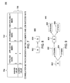
- FIG. 5 is a flowchart depicting processing logic of an execution manager component of the application, according to one embodiment presented in this disclosure.
- FIG. 6 is a flowchart depicting processing logic of an engine selector component of the application, according to one embodiment presented in this disclosure.
- FIG. 7 is a table depicting predefined correlations between elements of a decision matrix and job success rate, according to one embodiment presented in this disclosure.
- FIG. 8 depicts a data flow model of a sequential job, according to one embodiment presented in this disclosure.
- FIG. 9 depicts a job success rate model for the data flow model, according to one embodiment presented in this disclosure.
- FIG. 10 depicts a job success rate model for parallel execution of two instances of the data flow model, according to one embodiment presented in this disclosure.
- FIG. 11 depicts a job success rate model for parallel execution of two instances of the data flow model that further includes additional operators, according to one embodiment presented in this disclosure.
- FIG. 12 depicts a job success rate model for parallel execution of two instances of the data flow model with a system startup element, according to one embodiment presented in this disclosure.
- FIG. 13 depicts a parallel engine data flow, according to one embodiment presented in this disclosure.
- FIG. 14 illustrates a data flow model for a distributed computing data flow, according to one embodiment presented in this disclosure.
- FIG. 15 illustrates a data flow model that includes additional tasks performed for a distributed computing data flow, according to one embodiment presented in this disclosure.
- FIG. 16 is a flowchart depicting a method to determine an appropriate processing engine for a desired task, according to one embodiment presented in this disclosure.
- FIG. 17 is a flowchart depicting a method for data integration on retargetable engines in a networked environment, according to one embodiment presented in this disclosure.
- FIG. 18 is a flowchart depicting a subsequent method for data integration on retargetable engines in a networked environment, according to one embodiment presented in this disclosure.
- FIG. 19 is a block diagram illustrating components of a networked system configured for data integration on retargetable engines, according to one embodiment presented in this disclosure.
- FIG. 20 is a block diagram illustrating a cloud computing node for data integration on retargetable engines, according to one embodiment presented in this disclosure.
- FIG. 21 illustrates a cloud computing environment for data integration on retargetable engines, according to one embodiment presented in this disclosure.
- FIG. 22 illustrates abstraction model layers of the cloud computing environment for data integration on retargetable engines, according to one embodiment presented in this disclosure.
- a cloud computing environment also referred to herein as a cloud environment, may include different types of applications, of which one example is data integration applications.
- Data integration applications may often be designed to run in networked environments, such as symmetric multiprocessing (SMP), massively parallel processing (MPP), cluster, or grid environments, that include only a single data processing engine, also referred to herein as a processing engine.
- SMP symmetric multiprocessing
- MPP massively parallel processing
- cluster or grid environments, that include only a single data processing engine, also referred to herein as a processing engine.
- multiple data processing engines may coexist and share common resources.
- a client may submit a job request to the cloud computing environment, without needing to know or specify any particular data processing engine for running the desired job.
- An example of a job request is a request to execute a desired data flow.
- Programmatically choosing an appropriate data processing engine to run the desired job may be one of the challenges posed in migrating data integration to the cloud computing environment.
- an application is provided that is configured to select a data processing engine based on job characteristics and execution requirements.
- the data processing engine may be selected from a set of data processing engines of different types. Examples of different types of data processing engines include parallel processing engines and distributed computing engines.
- a parallel processing engine may be a scalable data integration processing engine
- an example of a distributed computing engine is a scalable distributed computing engine for cloud computing environments, such as HadoopTM, available from Apache Software Foundation.
- the distributed computing engine may also include a MapReduce model, which provides an interface to facilitate meeting various data integration needs.
- the respective paradigms of parallel processing engines and MapReduce each involves parallelizing programs by partitioning data across multiple processes in both a pipeline and partitioned manner.
- the two execution mechanisms may differ dramatically in terms latency, because the parallel processing engines may use inter-process communication (IPC) mechanisms for data transfer, whereas MapReduce applications may use file-system mechanisms for data transfer.
- IPC inter-process communication
- MapReduce applications may use file-system mechanisms for data transfer.
- jobs that do not cause pipeline breaks or stalls may often run faster—even an order of magnitude faster in some cases—on parallel processing engines than on MapReduce applications.
- the MapReduce paradigm may provide a higher level of fault tolerance than parallel processing engines at least in some embodiments, because all state information is stored on the file system. Doing so may at least in some cases avoid job failures caused by failure of a single mapper process.
- the higher level of fault tolerance may be especially important for any single, significantly large-scale parallel jobs, where the likelihood of a particular process failing may be relatively higher.
- data processing engines of multiple paradigms may be available to run a desired job. Accordingly, at least some embodiments disclosed herein provide empirical models for programmatically selecting an appropriate data processing engine for running the desired job and without requiring any user input specifying any desired data processing engine.
- the data processing engine may be selected based on predefined criteria. Examples of the predefined criteria include input data, job design complexity, application logic, performance requirement, latency requirement, fault tolerance, checkpoint restart, parallelism, resource utilization, parallel execution setup cost, etc.
- the appropriate data processing engine may vary from execution to execution, even for the same desired job. By providing retargetable engines, the needs of desired jobs may be more readily met, even as the needs change over time, such as in terms of data volume, required execution time, number of partitions, etc.
- One embodiment provides a decision-making job-execution system for efficiently running a data flow using a selected data processing engine in a networked environment, such as a cloud environment.
- the data processing engine may be selected upon determining that the data processing engine best satisfies predefined criteria, such as one or more of speed, efficiency, resource consumption, job execution success rate, user-specified execution time constraints, etc.
- the application may also include multiple application components, also referred to herein as components.
- FIG. 1 is a block diagram 100 illustrating components of an application 108 for data integration on retargetable engines in a networked environment, according to one embodiment presented in this disclosure.
- the application 108 includes a request handler 114 , an engine selector 116 , an engine manager 118 , a score composer 120 , and an execution manager 122 , also referred to herein as a process manager.
- the application 108 receives a job run request 104 from a client 102 .
- the application 108 may also receive additional information 106 associated with the job run request 104 , such as a data flow description, a job execution requirement, etc.
- the application 108 selects one of the parallel engines 112 in the execution environment 110 , for running the desired job.
- the desired job may then run on the selected parallel engine 112 .
- the application 108 may select a different parallel engine 112 for a subsequent execution of the application 108 in the execution environment 110 .
- the request handler 114 manages integration of and interaction among all the components of the application 108 .
- the request handler 114 may be responsible for invoking a series of operations needed for processing the job run request 104 .
- the engine manager 118 may be responsible for running the desired job on the appropriate processing engine. To this end, the engine manager 118 may invoke the engine selector 116 to select the appropriate processing engine based on predefined criteria.
- the engine manager 118 may also invoke the score composer 120 to generate an execution plan for the selected processing engine.
- the engine manager 118 may also invoke the execution manager 122 to implement the generated execution plan on the selected processing engine.
- the engine selector 116 may be responsible for selecting an appropriate processing engine for running a desired job.
- the processing engine may be selected based on a predefined model that has predefined criteria as inputs to the model. Examples of the predefined criteria include the job toplogy associated with the desired job, the parallelization capacity for each operator in the topology, the unit cost of reading and writing a fixed block of data to the backing store, the expected mean time between failures (MTBF) for the desired job, etc.
- the parallelization capacity also referred to herein as parallelization potential, represents a measure of scalability of an individual component in a data flow.
- the engine selector 116 may automatically select an appropriate processing engine on which to run a desired job, based on a size of the input data associated with the desired job and based further on the computing resources available in the cloud environment. Further, the same job may be submitted with different execution requirements, which may in turn result in selection of a different processing engine for running the job.
- the desired job is executed on a processing engine that is deemed by the application 108 as being most suitable for executing the desired job, based on predefined criteria such as job characteristics and execution requirements.
- a job execution plan for the desired job and that is specific to the selected processing engine is generated, and execution of the desired job commences on the selected processing engine based on the job execution plan. Consequently, desired jobs may be executed more efficiently in the networked environment at least in some cases.
- the application 108 in order to evaluate the predefined criteria to select a processing engine, the application 108 generates a decision matrix that may include multiple elements.
- the decision matrix includes a job topology complexity index, a job application logic complexity index, a job performance index, and a job high availability index.
- each index may be represented as a numerical or string value.
- a job success rate may also be determined.
- the job success rate may be considered part of or external to the decision matrix.
- each of the elements other than the job success rate may be individually examined to determine its impact on the job success rate.
- An appropriate processing engine may then be selected based on the decision matrix.
- the job success rate may also be referred to as a job success likelihood or a job success probability.
- the application 108 uses empirical modeling to determine the job success rate and to select the appropriate processing engine.
- a data flow includes one or more branches, and each branch is either independent, which is characterized by no sharing of operators, or correlated with another branch via one or more operators.
- a branch contains a chain of operators arranged in terms of producing and consuming sequences.
- the failure rate of an operator is equal to the estimated execution time divided by the MTBF, whereas the success rate of an operator is equal to one minus its failure rate.
- the success rate of a branch on one partition is equal to the multiplication of the success rate of each operator on that partition, while the success rate of a branch on all partitions is equal to the average success rate of all partitions.
- the success rate of a branch counting startup is equal to the average success rate of all partitions multiplied by the success rate of branch startup.
- the success rate of a data flow is equal to the minimum success rate among all branches.
- the success rate is determined by the success rate of all physical nodes and an extra cost needed for maintaining a desired level of high availability.
- FIG. 2 is a data flow diagram 200 depicting processing logic of the request handler 114 of FIG. 1 , according to one embodiment presented in this disclosure.
- the request handler 114 determines the type of the received request (step 220 ).
- the request handler 114 supports different types of requests, including a check engine request, a validate job request, and a run job request. If the request is a check engine request, then the request handler 114 invokes a check engine handler 250 in order to generate a list of available processing engines. If the request is a validate job request, then the request handler 114 invokes a validate job handler 230 in order to verify the design and configuration of a specified data flow to ensure that the data flow is valid.
- the request handler 114 invokes a run job handler 240 to manage aspects pertaining to executing a desired job.
- the processing logic and the types of requests supported by the request handler 114 may be tailored to suit the needs of a particular case.
- FIG. 3 is a flowchart 300 depicting processing logic of the engine manager 118 of FIG. 1 , according to one embodiment presented in this disclosure.
- the flowchart 300 begins at step 310 , where the engine manager 118 receives request information such as a data flow description, job execution requirements, etc.
- the engine manager 118 determines whether a processing engine is pre-selected. If not, then the engine manager 118 selects a suitable processing engine based on the request information and according to the empirical model described above (step 325 ).
- the engine manager 118 generates an execution plan for the desired job and specific to the selected or preselected processing engine.
- the engine manager 118 executes the desired job by running the execution plan. After the step 340 , the flowchart 300 ends.
- FIG. 4 is a flowchart 400 depicting processing logic of the score composer 120 of FIG. 1 , according to one embodiment presented in this disclosure.
- the flowchart 400 begins at step 410 , where the score composer 120 receives request information such as a data flow description, job execution requirements, a target engine specification, etc.
- the score composer 120 determines whether the target engine is the parallel processing engine. If so, the score composer 120 generates a parallel execution plan for the desired job (step 425 ). On the other hand, if the score composer 120 determines that the target engine is the distributed processing engine rather than the parallel processing engine (step 430 ), then the score composer 120 generates a distributed execution plan for the desired job (step 435 ).
- the score composer 120 then serializes and stores the generated parallel or distributed execution plan to storage (step 440 ). After the step 440 or if no processing engine is selected, the flowchart 400 ends.
- the number and specific types of processing engines supported may be tailored to suit the needs of a particular case.
- FIG. 5 is a flowchart 500 depicting processing logic of the execution manager 122 of FIG. 1 , according to one embodiment presented in this disclosure.
- the flowchart 500 begins at step 510 , where the execution manager 122 receives a job execution plan for the desired job. The execution manager 122 then determines the type of the target engine based on the job execution plan. If the target engine is the parallel processing engine (step 520 ), the execution manager 122 commences execution of the job execution plan on the parallel processing engine in the networked environment (step 525 ). On the other hand, if the target engine is the distributed processing engine rather than the parallel processing engine ( 530 ), then the execution manager 122 commences execution of the job execution plan on the distributed computing engine in the networked environment (step 535 ). After the steps 525 or 535 or if no matching processing engine is identified, the flowchart 500 ends.
- FIG. 6 is a flowchart 600 depicting processing logic of the engine selector 116 of FIG. 1 , according to one embodiment presented in this disclosure.
- the flowchart 600 begins at step 601 , where the engine selector 116 receives request information such as a data flow description, job execution requirements, etc.
- the engine selector 116 selects a processing engine based on predefined criteria.
- the predefined criteria may be a job success rate that is determined based on a decision matrix generated by the engine selector 116 .
- the processing engine having the highest job success rate is selected.
- the decision matrix may include four elements cover various factors associated with a job run request, where the factors may be static or dynamic.
- the decision matrix may include the job topology complexity index, the job application complexity index, the job performance index, and the job high availability index.
- the engine selector 116 performs one or more of the following steps to generate the decision matrix.
- the engine selector 116 analyzes the data flow topology of the desired job (step 602 ) and application logic of each stage in the data flow (step 604 ).
- the engine selector 116 estimates resource utilization associated with the desired job (step 606 ).
- the engine selector 116 then examines job execution requirements (step 608 ) and considers fault tolerance checkpoints and restart requirements, if any (step 610 ). In performing these steps, the engine selector 116 may determine one or more of a job topology complexity index 616 , a job application logic complexity index 620 , a job performance index 624 , and a job high availability index 628 .
- a single index of each type may be generated for a given job, or multiple indices of the same type may be generated for the available processing environment, each index specific to a different processing environment.
- the engine selector 116 may generate one or more of a startup cost 618 associated with the job topology complexity index 616 , a runtime cost 622 associated with the job application logic complexity index 620 , a runtime cost 626 associated with the job performance index 624 , and a startup and runtime cost 630 associated with the job high availability index 628 .
- the engine selector 116 may then determine a job success rate 614 for each available processing environment, based on the decision matrix (step 612 ). After the step 612 , the flowchart 600 ends.
- the job topology complexity index is determined as a predefined function of one or more of number of branches in the data flow of the desired job, the number of operators in each branch, the number of data sources, the number of data sinks, and the number of operators requiring intermediate storage.
- the job application logic complexity index is determined as a predefined function of one or more of the number of operators that require data be sorted and the number of operators which processing logic includes mapping, merging, aggregation, transformation, passthrough, etc.
- the job performance index is determined as a measure of estimated resource consumption and as a function of job statistics obtained from previous executions of the desired job.
- the job high availability index is determined based on whether a given processing engine supports fault tolerance and job restart.
- the elements of the decision matrix and the predefined functions may be tailored to suit the needs of a particular case.
- FIG. 7 is a table 700 depicting predefined correlations 706 between elements of the decision matrix 702 and job success rate, according to one embodiment presented in this disclosure.
- the job success rate may be determined by the empirical model described above.
- the correlation between the job success rate and each element in the decision matrix is represented as a down arrow ( ⁇ ) to indicate that the job success rate decreases and an up arrow ( ⁇ ) to indicate that the success rate increases, when the each element of the decision matrix changes according to values 704 .
- the job success rate is inversely correlated with the job topology complexity index and the job application logic complexity index, respectively.
- the job success rate is directly correlated with the job performance index and the job high available index, respectively.
- the job high availability index may affect the other indices. For instance, in order to maintain high availability, a processing engine may in some cases need to incur input/output (I/O) costs from reading and writing data to and from storage before incurring processing costs in sending the data to the next process. Adding extra tasks for data transport increases the values of the job topology complexity index and the job application logic complexity index and decreases the value of the job performance index.
- the elements of the decision matrix and the correlations may be tailored to suit the needs of a particular case.
- FIG. 8 depicts a data flow model 800 of a sequential job, according to one embodiment presented in this disclosure.
- the data flow model 800 is a distributed processing data flow rather than a parallel processing data flow.
- the data flow model 800 has two data flow objects including a first operator 802 and a second operator 804 .
- a model may first be generated based on the data flow model 800 .
- FIG. 9 depicts a job success rate model 900 for the data flow model 800 of FIG. 8 , according to one embodiment presented in this disclosure.
- the job success rate model 900 includes multiple scenarios.
- the scenarios include a scenario 902 in which the first operator 802 succeeds, a scenario in which the first operator 802 fails, a scenario 906 in which the second operator 804 succeeds, and a scenario 908 in which the second operator 804 fails.
- Let F A represent the failure rate of the first operator 802
- F B represent the failure rate of the second operator 804 .
- SuccessRate (1 ⁇ T A /MTBF A )*(1 ⁇ T B /MTBF B ) (Equation 2)
- T A refers to total execution time of the first operator 802
- T B refers to the total execution time of the second operator 804
- MTBF A refers to the mean time between failures of operator A
- MTBF B refers to the mean time between failures of operator B.
- a network switch may time out when an operator is making a network call, or the file system may hang when an operator is writing to the file system.
- the MTBF describes the expected time it takes, on average, for the operator to fail due to a hardware or software problem.
- FIG. 10 depicts a job success rate model 1000 for parallel execution of two instances 1002 of the data flow model 800 of FIG. 8 , according to one embodiment presented in this disclosure. Assume that the entire job is successful only if both pipelines are successful, each pipeline executing a separate instance 1002 of the data flow model.
- FIG. 11 depicts a job success rate model 1100 for parallel execution of two instances 1102 of the data flow model 800 that further includes additional operators, according to one embodiment presented in this disclosure.
- the additional operators may include at least operators 1104 and 1106 .
- the job success rate model 1100 generalizes the number of operators in the data flow to an arbitrary number of operators N.
- FIG. 12 depicts a job success rate model 1200 for parallel execution of two instances of the data flow model with a system startup element 1202 , according to one embodiment presented in this disclosure.
- a parallel processing engine has an initial startup phase, during which the parallel processing engine parses an Orchestrate Shell (OSH) script, invokes the score composer 120 to generate a parallel engine score to represent the parallel execution plan, and instantiates a network of processes on a set of nodes that form a parallel engine cluster for the parallel processing engine.
- the initial startup phase is represented as the system startup element 1202 in FIG. 12 . After establishing all required processes, the data processing phase is entered.
- OSH Orchestrate Shell
- the processes of different types include a conductor process, section leader processes, and player processes, which are communicatively organized into a hierarchy, with the conductor process as the root node in the hierarchy and with the player processes as leaf nodes in the hierarchy. At least in some embodiments, the player processes are also communicatively connected to one another.
- FIG. 13 depicts a parallel engine data flow 1300 , according to one embodiment presented in this disclosure.
- a parallel engine data flow may contain any number of branches, each branch including a chain of operators of selected from a set of operators 1302 .
- the success rate for each branch may be determined using the empirical model described above.
- the success rate for the entire parallel engine data flow 1300 may then be determined as the minimum success rate among all branches contained in the parallel engine data flow 1300 .
- the parallel engine data flow 1300 merges and branches out at an operator 1302 3 .
- the parallel engine data flow 1300 may be considered to include the following distinct branches:
- the job success rate of the parallel engine data flow 1300 may be determined by performing a set of operations including identifying all the branches in the parallel engine data flow.
- the set of operations further includes determining a success rate for each branch using the empirical model described above.
- the set of operations further includes designating the minimum success rate among the branches as the job success rate for the parallel engine data flow 1300 .
- the success rate for each branch in the parallel engine data flow may be determined based on a predefined algorithm.
- One such algorithm is illustrated in Table II.
- the job success rate of any parallel engine data flow may be determined more efficiently or conveniently at least in some cases. Further, the operations for determining the job success rate and for identifying branches may be tailored to suit the needs of a particular case.
- FIG. 14 illustrates a data flow model 1400 for a distributed computing data flow, according to one embodiment presented in this disclosure.
- the data flow model 1400 is described in conjunction with the MapReduce model of Hadoop.
- the data flow model 1400 includes a map wrapper 1402 for a first operator and further includes a reducer wrapper 1404 for a second operator.
- the map wrapper 1402 is a wrapper function for a map operation
- the reduce wrapper 1404 is a wrapper function for a reduce operation.
- the map operation accepts a series of key/value pairs, processes each pair, and generates zero or more output key/value pairs, while the reduce operation iterates through the values associated with each key and produces zero or more outputs.
- the Hadoop framework performs additional tasks to manage input split, output serialization, replication, deserialization, etc.
- FIG. 15 illustrates a data flow model 1500 that includes additional tasks performed for a distributed computing data flow, according to one embodiment presented in this disclosure.
- the additional tasks are represented by split operations 1502 , sort operations 1504 and merge operations 1506 .
- the Hadoop engine may include checkpoint/resume capability and speculative execution mode, such that if one task fails on one physical node, the failed task may be moved to a different node for retry.
- the default replication factor of the file-system component of Hadoop may be configured to an arbitrarily high value, such that ever job eventually succeeds unless each physical node in the cluster fails.
- HDFS Hadoop Distributed File System
- distributed computing jobs such as Hadoop jobs
- the criteria used in selecting the appropriate processing engine further takes into consideration other factors such as a service level agreement associated with a requesting client, a hardware investment factor, a system response time factor, a job complexity factor, etc.
- FIG. 16 is a flowchart depicting a method 1600 to determine an appropriate processing engine for a desired task, according to one embodiment presented in this disclosure.
- the method 1600 begins at step 1610 , where the application 108 reads a predefined script and builds a predefined object to represent the data flow.
- An example of the predefined script is an OSH script, while an example of a predefined object is an Applied Parallel Technologies step object, also referred to as an APT_Step object.
- the application 108 reads a predefined configuration file, such as an operator reliability profile. In some embodiments, each operator not having any entry in the operator reliability profile is assumed to have a failure rate of 1*10 ⁇ 6 .
- the application 108 evaluates the job against one or more predefined rules. To this end, the application 108 may determine whether the desired job is a real-time job that requires low latency, whether the desired job contains message queuing (MQ) (i.e., the data flow contains an MQ connector that requires guaranteed message delivery), and whether the desired job involves database writes. If so, the application 108 runs the data flow on the parallel processing engine (step 1690 ). Otherwise, the method 1600 proceeds to step 1640 .
- MQ message queuing
- the application 108 may take into account resource utilization estimates, e.g., CPU utilization, total execution time for individual operators, I/O activity estimates, etc. Using the resource utilization estimates as input into the job success rate model for the parallel processing engine, in order to determine a job success rate. To this end, the application 108 may generate a decision matrix for the parallel processing engine (step 1640 ) and then computes a job success rate for the parallel processing engine and by using the empirical model described above (step 1650 ). The application 108 may then generate a decision matrix for the distributed computing engine (step 1660 ) and then computes a job success rate for the distributed computing engine and by using the empirical model described above (step 1670 ).
- resource utilization estimates e.g., CPU utilization, total execution time for individual operators, I/O activity estimates, etc.
- the application 108 may generate a decision matrix for the parallel processing engine (step 1640 ) and then computes a job success rate for the parallel processing engine and by using the empirical model described above (step 1650 ).
- the application 108 determines which job success rate is higher (step 1680 ). If the job success rate for the parallel processing engine is higher, then the application 108 runs the desired job on the parallel processing engine (step 1690 ). On the other hand, if the job success rate of the distributed computing engine is higher, then the application 108 runs the desired job on the distributed computing engine (step 1695 ). After the step 1690 or 1695 , the method 1600 terminates.
- FIG. 17 is a flowchart depicting a method 1700 for data integration on retargetable engines in a networked environment, according to one embodiment presented in this disclosure.
- the method 1700 begins at step 1710 , where the application 108 receives a first request to execute a data flow model in the networked environment.
- the networked environment includes data processing engines of different types. Each of the data processing engines has a different set of characteristics.
- the data flow model includes one or more data flow objects.
- the application 108 programmatically selects a first data processing engine from the data processing engines, based on a first predefined set of criteria and the sets of characteristics of the data processing engines.
- the application 108 executes the data flow model using the first data processing engine and responsive to the first request. After the step 1730 , the method 1700 terminates.
- FIG. 18 is a flowchart depicting a subsequent method 1800 for data integration on retargetable engines in a networked environment, according to one embodiment presented in this disclosure.
- the method 1800 begins at step 1810 where, subsequent to executing the data flow model using the first data processing engine, the application 108 receives a second request to execute the data flow model in the networked environment.
- the application 108 programmatically selects a second data processing engine of a different type than the first data processing engine, based on a second predefined set of criteria and the sets of characteristics of the data processing engines.
- the application 108 executes the data flow model using the second data processing engine and responsive to the second request. After the step 1830 , the method 1800 terminates.
- Embodiments disclosed herein provide techniques for data integration on retargetable engines in desired network environments, such as cloud computing environments.
- desired network environments such as cloud computing environments.
- data flows may be executed more efficiently at least in some cases—at least relative to alternative approaches that rely on other bases for selecting data processing engines.
- alternative approaches include approaches that do not consider the predefined criteria disclosed herein and approaches that rely on user input specifying a desired data processing engine to use.
- FIG. 19 is a block diagram illustrating components of a networked system 1900 configured for data integration on retargetable engines, according to one embodiment presented in this disclosure.
- the networked system 1900 includes a computer 1902 .
- the computer 1902 may also be connected to other computers via a network 1930 .
- the network 1930 may be a telecommunications network and/or a wide area network (WAN).
- the network 1930 is the Internet.
- the computer 1902 generally includes a processor 1904 connected via a bus 1912 to a memory 1906 , a network interface device 1910 , a storage 1908 , an input device 1914 , and an output device 1916 .
- the computer 1902 is generally under the control of an operating system. Examples of operating systems include IBM z/OS®, UNIX, versions of the Microsoft Windows® operating system, and distributions of the Linux® operating system. More generally, any operating system supporting the functions disclosed herein may be used.
- the processor 1904 is included to be representative of a single CPU, multiple CPUs, a single CPU having multiple processing cores, and the like.
- the memory 1906 may be a random access memory.
- the memory 1906 is shown as a single identity, it should be understood that the memory 1906 may comprise a plurality of modules, and that the memory 1906 may exist at multiple levels, from high speed registers and caches to lower speed but larger DRAM chips.
- the network interface device 1910 may be any type of network communications device allowing the computer 1902 to communicate with other computers via the network 1930 .
- the storage 1908 may be a persistent storage device. Although the storage 1908 is shown as a single unit, the storage 1908 may be a combination of fixed and/or removable storage devices, such as fixed disc drives, solid state drives, floppy disc drives, tape drives, removable memory cards or optical storage.
- the memory 1906 and the storage 1908 may be part of one virtual address space spanning multiple primary and secondary storage devices.
- the input device 1914 may be any device for providing input to the computer 1902 .
- a keyboard, a mouse, a touchpad, voice commands, or any combination thereof may be used.
- the output device 1916 may be any device for providing output to a user of the computer 1902 .
- the output device 1916 may be any display screen or set of speakers.
- the output device 1916 and input device 1914 may be combined.
- a display screen with an integrated touch-screen may be used.
- the memory 1906 of the computer 1902 includes the application 108 of FIG. 1 .
- one or more of the components of the application 108 as depicted in FIG. 1 may execute on the computer 1902 or on one or more other computers operatively connected to the computer 1902 via the network 1930 .
- the client 102 and the execution environment 110 of FIG. 1 may each also execute on one or more other computers operatively connected to the computer 1902 via the network 1930 .
- aspects presented in this disclosure may be embodied as a system, method or computer program product. Accordingly, aspects disclosed herein may take the form of an entirely hardware embodiment, an entirely software embodiment (including firmware, resident software, micro-code, etc.) or an embodiment combining software and hardware aspects that may all generally be referred to herein as a “circuit,” “module” or “system.” Furthermore, aspects disclosed herein may take the form of a computer program product embodied in one or more computer readable medium(s) having computer readable program code embodied thereon.
- the computer readable medium may be a computer readable signal medium or a computer readable storage medium.
- a computer readable storage medium may be, for example, but not limited to, an electronic, magnetic, optical, electromagnetic, infrared, or semiconductor system, apparatus, or device, or any suitable combination of the foregoing.
- a computer readable storage medium may be any tangible medium that can contain, or store a program for use by or in connection with an instruction execution system, apparatus, or device.
- a computer readable signal medium may include a propagated data signal with computer readable program code embodied therein, for example, in baseband or as part of a carrier wave. Such a propagated signal may take any of a variety of forms, including, but not limited to, electro-magnetic, optical, or any suitable combination thereof.
- a computer readable signal medium may be any computer readable medium that is not a computer readable storage medium and that can communicate, propagate, or transport a program for use by or in connection with an instruction execution system, apparatus, or device.
- Program code embodied on a computer readable medium may be transmitted using any appropriate medium, including but not limited to wireless, wireline, optical fiber cable, RF, etc., or any suitable combination of the foregoing.
- Computer program code for carrying out operations for aspects disclosed herein may be written in any combination of one or more programming languages, including an object oriented programming language such as Java, Smalltalk, C++ or the like and conventional procedural programming languages, such as the “C” programming language or similar programming languages.
- the program code may execute entirely on the computer of a user, partly on the computer of the user, as a stand-alone software package, partly on the computer of the user and partly on a remote computer, or entirely on the remote computer or server.
- the remote computer may be connected to the computer of the user via any type of network, including a local area network (LAN) or a wide area network (WAN), or the connection may be made to an external computer (for example, through the Internet using an Internet Service Provider).
- LAN local area network
- WAN wide area network
- Internet Service Provider for example, AT&T, MCI, Sprint, EarthLink, MSN, GTE, etc.
- These computer program instructions may also be stored in a computer readable medium that can direct a computer, other programmable data processing apparatus, or other devices to function in a particular manner, such that the instructions stored in the computer readable medium produce an article of manufacture including instructions which implement the function/act specified in the flowchart or block diagram block or blocks.
- the computer program instructions may also be loaded onto a computer, other programmable data processing apparatus, or other devices to cause a series of operational steps to be performed on the computer, other programmable apparatus or other devices to produce a computer implemented process such that the instructions which execute on the computer or other programmable apparatus provide processes for implementing the functions/acts specified in the flowchart or block diagram block or blocks.
- Cloud computing is a model of service delivery for enabling convenient, on-demand network access to a shared pool of configurable computing resources (e.g., networks, network bandwidth, servers, processing, memory, storage, applications, virtual machines, and services) that can be rapidly provisioned and released with minimal management effort or interaction with a provider of the service.
- This cloud model may include at least five characteristics, at least three service models and at least four deployment models.
- On-demand self-service a cloud consumer can unilaterally provision computing capabilities, such as server time and network storage, as needed automatically without requiring human interaction with the service's provider.
- Resource pooling the provider's computing resources are pooled to serve multiple consumers using a multi-tenant model, with different physical and virtual resources dynamically assigned and reassigned according to demand. There is a sense of location independence in that the consumer generally has no control or knowledge over the exact location of the provided resources but may be able to specify location at a higher level of abstraction (e.g., country, state or datacenter).
- Rapid elasticity capabilities can be rapidly and elastically provisioned, in some cases automatically, to quickly scale out and rapidly released to quickly scale in. To the consumer, the capabilities available for provisioning often appear to be unlimited and can be purchased in any quantity at any time.
- Measured service cloud systems automatically control and optimize resource use by leveraging a metering capability at some level of abstraction appropriate to the type of service (e.g., storage, processing, bandwidth and active user accounts). Resource usage can be monitored, controlled and reported providing transparency for both the provider and consumer of the utilized service.
- level of abstraction appropriate to the type of service (e.g., storage, processing, bandwidth and active user accounts).
- SaaS Software as a Service: the capability provided to the consumer is to use the provider's applications running on a cloud infrastructure.
- the applications are accessible from various client devices through a thin client interface such as a web browser (e.g., web-based e-mail).
- a web browser e.g., web-based e-mail
- the consumer does not manage or control the underlying cloud infrastructure including network, servers, operating systems, storage or even individual application capabilities, with the possible exception of limited user-specific application configuration settings.
- PaaS Platform as a Service
- the consumer does not manage or control the underlying cloud infrastructure including networks, servers, operating systems or storage, but has control over the deployed applications and possibly application hosting environment configurations.
- IaaS Infrastructure as a Service
- the consumer does not manage or control the underlying cloud infrastructure but has control over operating systems storage, deployed applications, and possibly limited control of select networking components (e.g., host firewalls).
- Private cloud the cloud infrastructure is operated solely for an organization. It may be managed by the organization or a third party and may exist on-premises or off-premises.
- Public cloud the cloud infrastructure is made available to the general public or a large industry group and is owned by an organization selling cloud services.
- Hybrid cloud the cloud infrastructure is a composition of two or more clouds (private, community, or public) that remain unique entities but are bound together by standardized or proprietary technology that enables data and application portability (e.g., cloud bursting for load-balancing between clouds).
- a cloud computing environment is service oriented with a focus on statelessness, low coupling, modularity and semantic interoperability.
- An infrastructure comprising a network of interconnected nodes.
- Cloud computing node 10 is only one example of a suitable cloud computing node and is not intended to suggest any limitation as to the scope of use or functionality of embodiments of the invention described herein. Regardless, cloud computing node 10 is capable of being implemented and/or performing any of the functionality set forth hereinabove.
- cloud computing node 10 there is a computer system/server 12 , which is operational with numerous other general purpose or special purpose computing system environments or configurations.
- Examples of well-known computing systems, environments, and/or configurations that may be suitable for use with computer system/server 12 include, but are not limited to, personal computer systems, server computer systems, thin clients, thick clients, hand-held or laptop devices, multiprocessor systems, microprocessor-based systems, set top boxes, programmable consumer electronics, network PCs, minicomputer systems, mainframe computer systems, and distributed cloud computing environments that include any of the above systems or devices, and the like.
- Computer system/server 12 may be described in the general context of computer system-executable instructions, such as program modules, being executed by a computer system.
- program modules may include routines, programs, objects, components, logic, data structures, and so on that perform particular tasks or implement particular abstract data types.
- Computer system/server 12 may be practiced in distributed cloud computing environments where tasks are performed by remote processing devices that are linked through a communications network.
- program modules may be located in both local and remote computer system storage media including memory storage devices.
- computer system/server 12 in cloud computing node 10 is shown in the form of a general-purpose computing device.
- the components of computer system/server 12 may include, but are not limited to, one or more processors or processing units 16 , a system memory 28 , and a bus 18 that couples various system components including system memory 28 to processor 16 .
- Bus 18 represents one or more of any of several types of bus structures, including a memory bus or memory controller, a peripheral bus, an accelerated graphics port, and a processor or local bus using any of a variety of bus architectures.
- bus architectures include Industry Standard Architecture (ISA) bus, Micro Channel Architecture (MCA) bus, Enhanced ISA (EISA) bus, Video Electronics Standards Association (VESA) local bus and Peripheral Component Interconnects (PCI) bus.
- Computer system/server 12 typically includes a variety of computer system readable media. Such media may be any available media that is accessible by computer system/server 12 , and it includes both volatile and non-volatile media, removable and non-removable media.
- System memory 28 can include computer system readable media in the form of volatile memory, such as random access memory (RAM) 30 and/or cache memory 32 .
- Computer system/server 12 may further include other removable/non-removable, volatile/non-volatile computer system storage media.
- storage system 34 can be provided for reading from and writing to a non-removable, non-volatile magnetic media (not shown and typically called a “hard drive”).
- a magnetic disk drive for reading from and writing to a removable, non-volatile magnetic disk (e.g., a “floppy disk”).
- an optical disk drive for reading from or writing to a removable, non-volatile optical disk such as a CD-ROM, DVD-ROM or other optical media can be provided.
- memory 28 may include at least one program product having a set (e.g., at least one) of program modules that are configured to carry out the functions of embodiments of the invention.
- Program/utility 40 having a set (at least one) of program modules 42 , may be stored in memory 28 by way of example, and not limitation, as well as an operating system, one or more application programs, other program modules, and program data. Each of the operating system, one or more application programs, other program modules and program data or some combination thereof, may include an implementation of a networking environment.
- Program modules 42 generally carry out the functions and/or methodologies of embodiments of the invention as described herein.
- Computer system/server 12 may also communicate with one or more external devices 14 such as a keyboard, a pointing device, a display 24 , etc.; one or more devices that enable a user to interact with computer system/server 12 ; and/or any devices (e.g., network card, modem, etc.) that enable computer system/server 12 to communicate with one or more other computing devices. Such communication can occur via I/O interfaces 22 . Still yet, computer system/server 12 can communicate with one or more networks such as a local area network (LAN), a general wide area network (WAN), and/or a public network (e.g., the Internet) via network adapter 20 . As depicted, network adapter 20 communicates with the other components of computer system/server 12 via bus 18 .
- LAN local area network
- WAN wide area network
- public network e.g., the Internet
- cloud computing environment 50 comprises one or more cloud computing nodes 10 with which local computing devices used by cloud consumers, such as, for example, personal digital assistant (PDA) or cellular telephone 54 A, desktop computer 54 B, laptop computer 54 C and/or automobile computer system 54 N may communicate.
- Nodes 10 may communicate with one another. They may be grouped (not shown) physically or virtually, in one or more networks, such as Private, Community, Public, or Hybrid clouds as described hereinabove, or a combination thereof.
- This allows cloud computing environment 50 to offer infrastructure, platforms and/or software as services for which a cloud consumer does not need to maintain resources on a local computing device.
- computing devices 54 A-N shown in FIG. 21 are intended to be illustrative only and that computing nodes 10 and cloud computing environment 50 can communicate with any type of computerized device over any type of network and/or network addressable connection (e.g., using a web browser).
- FIG. 22 a set of functional abstraction layers provided by cloud computing environment 50 ( FIG. 21 ) for data integration on retargetable engines is shown. It should be understood in advance that the components, layers and functions shown in FIG. 21 are intended to be illustrative only and embodiments of the invention are not limited thereto. As depicted, the following layers and corresponding functions are provided:
- Hardware and software layer 60 includes hardware and software components.
- hardware components include mainframes, in one example IBM® zSeries® systems; RISC (Reduced Instruction Set Computer) architecture based servers, in one example IBM pSeries® systems; IBM xSeries® systems; IBM BladeCenter® systems; storage devices; networks and networking components.
- software components include network application server software, in one example IBM WebSphere® application server software; and database software, in one example IBM DB2® database software.
- IBM, zSeries, pSeries, xSeries, BladeCenter, WebSphere, and DB2 are trademarks of International Business Machines Corporation registered in many jurisdictions worldwide
- Virtualization layer 62 provides an abstraction layer from which the following examples of virtual entities may be provided: virtual servers; virtual storage; virtual networks, including virtual private networks; virtual applications and operating systems; and virtual clients.
- management layer 64 may provide the functions described below.
- Resource provisioning provides dynamic procurement of computing resources and other resources that are utilized to perform tasks within the cloud computing environment.
- Metering and Pricing provide cost tracking as resources are utilized within the cloud computing environment, and billing or invoicing for consumption of these resources. In one example, these resources may comprise application software licenses.
- Security provides identity verification for cloud consumers and tasks, as well as protection for data and other resources.
- User portal provides access to the cloud computing environment for consumers and system administrators.
- Service level management provides cloud computing resource allocation and management such that required service levels are met.
- Service Level Agreement (SLA) planning and fulfillment provide pre-arrangement for, and procurement of, cloud computing resources for which a future requirement is anticipated in accordance with an SLA.
- the SLA generally specifies the services, priorities, responsibilities, guarantees and/or warranties that exist between a service provider and a customer.
- Workloads layer 66 provides examples of functionality for which the cloud computing environment may be utilized. Examples of workloads and functions which may be provided from this layer include: mapping and navigation; software development and lifecycle management; virtual classroom education delivery; data analytics processing; transaction processing; and mobile desktop.
- Cloud computing generally refers to the provision of scalable computing resources as a service over a network. More formally, cloud computing may be defined as a computing capability that provides an abstraction between the computing resource and its underlying technical architecture (e.g., servers, storage, networks), enabling convenient, on-demand network access to a shared pool of configurable computing resources that can be rapidly provisioned and released with minimal management effort or service provider interaction.
- cloud computing allows a user to access virtual computing resources (e.g., storage, data, applications, and even complete virtualized computing systems) in “the cloud,” without regard for the underlying physical systems (or locations of those systems) used to provide the computing resources.
- cloud computing resources are provided to a user on a pay-per-use basis, where users are charged only for the computing resources actually used (e.g., an amount of storage space consumed by a user or a number of virtualized systems instantiated by the user).
- a user can access any of the resources that reside in the cloud at any time, and from anywhere across the Internet.
- a user may request a data flow to be executed on an appropriate data processing engine available in the cloud.
- the application 108 may determine the appropriate data processing engine based on predefined criteria and according to an empirical model disclosed herein.
- the user may request execution of data flows and access results thereof, from any computing system attached to a network connected to the cloud (e.g., the Internet) and be charged based on the processing environment(s) used.
- each block in the flowchart or block diagrams may represent a module, segment, or portion of code, which comprises one or more executable instructions for implementing the specified logical function(s).
- the functions noted in the block may occur out of the order noted in the figures.
- two blocks shown in succession may, in fact, be executed substantially concurrently, or the blocks may sometimes be executed in the reverse order, depending upon the functionality involved.
- Each block of the block diagrams or flowchart illustration, and combinations of blocks in the block diagrams or flowchart illustration can be implemented by special-purpose hardware-based systems that perform the specified functions or acts, or combinations of special purpose hardware and computer instructions.
Abstract
Description
SuccessRate=(1−F A)*(1−F B) (Equation 1)
In cases where an application is installed but is not running and hence cannot fail, the above model may be further expressed as:
SuccessRate=(1−T A/MTBFA)*(1−T B/MTBFB) (Equation 2)
Where TA refers to total execution time of the
SuccessRate=0.5*(1−T A1/MTBFA)*(1−T B1/MTBFB)+0.5*(1−T A2/MTBFA)*(1−T B2/MTBFB) (Equation 3)
In one embodiment, to generalize the above equation further, the job success rate for a data flow with n-way parallel equal partition may be modeled as:
SuccessRate=Σ1/n *(1−T A1/MTBFA)*(1−T B1/MTBFB) (Equation 4)
where i is from 1 to n.
SuccessRate=Σ1/n*(1−T Ai/MTBFA)*(1−T Bi/MTBFB)* . . . *(1−T Ni/MTBFN) (Equation 5)
SuccessRate=(1−StartupFailureRate)*Σ1/n*(1−T Ai/MTBFA)*(1−T Bi/MTBFB)* . . . *(1−T Ni/MTBFN) (Equation 6)
| TABLE I |
| Branches in the parallel engine data flow |
| Branch 1: | {Op1, Op2, Op3, Op4, Op5, . . . , OpN} | ||
| Branch 2: | {Op1, Op2, Op3, OpK4, OpK5, . . . , OpKn} | ||
| Branch 3: | {OpK1, OpK2, Op3, Op4, Op5, . . . , OpN} | ||
| Branch 4: | {OpK1, OpK2, Op3, OpK4, OpK5, . . . , OpKn} | ||
The job success rate of the parallel
| TABLE II |
| Algorithm for identifying branches in the parallel |
| 1. | Select an input data source operator that has not yet been searched. |
| 2. | Select one of output links that has not yet been checked. |
| 3. | Follow the output link to its consuming operator, marking the output |
| link as checked. | |
| 4. | If the current operator is a data sink or does not have any unchecked |
| output links, go to step 6. | |
| 5. | Repeat steps 2 to 4. |
| 6. | Start from the current operator. |
| 7. | Follow the most recently traversed input link to its producing |
| operator. | |
| 8. | If the producing operator has at least another consuming operator |
| attached to it, go to that operator and repeat | |
| 9. | Repeat steps 7 to 8 until the input data source operator from |
| reached. | |
| 10. | Repeat steps 2 to 9 until all output links of the input data source |
| operator from | |
| 11. | Mark the input data source operator as searched. |
| 12. | Unmark all links that are checked. |
| 13. | Repeat steps 1 to 12 until all input data source operators have been |
| searched. | |
Hence, the job success rate of any parallel engine data flow may be determined more efficiently or conveniently at least in some cases. Further, the operations for determining the job success rate and for identifying branches may be tailored to suit the needs of a particular case.
SuccessRate=1−F 1 *F 2 * . . . *F n (Equation 7)
where Fi has a value range of (0, 1) and represents a failure rate of a physical node i.
Claims (17)
Priority Applications (1)
| Application Number | Priority Date | Filing Date | Title |
|---|---|---|---|
| US13/842,484 US9401835B2 (en) | 2013-03-15 | 2013-03-15 | Data integration on retargetable engines in a networked environment |
Applications Claiming Priority (1)
| Application Number | Priority Date | Filing Date | Title |
|---|---|---|---|
| US13/842,484 US9401835B2 (en) | 2013-03-15 | 2013-03-15 | Data integration on retargetable engines in a networked environment |
Publications (2)
| Publication Number | Publication Date |
|---|---|
| US20140280441A1 US20140280441A1 (en) | 2014-09-18 |
| US9401835B2 true US9401835B2 (en) | 2016-07-26 |
Family
ID=51533351
Family Applications (1)
| Application Number | Title | Priority Date | Filing Date |
|---|---|---|---|
| US13/842,484 Expired - Fee Related US9401835B2 (en) | 2013-03-15 | 2013-03-15 | Data integration on retargetable engines in a networked environment |
Country Status (1)
| Country | Link |
|---|---|
| US (1) | US9401835B2 (en) |
Cited By (1)
| Publication number | Priority date | Publication date | Assignee | Title |
|---|---|---|---|---|
| US10296425B2 (en) | 2017-04-20 | 2019-05-21 | Bank Of America Corporation | Optimizing data processing across server clusters and data centers using checkpoint-based data replication |
Families Citing this family (18)
| Publication number | Priority date | Publication date | Assignee | Title |
|---|---|---|---|---|
| GB2506595A (en) * | 2012-10-02 | 2014-04-09 | Ibm | Provisioning systems in parallel based on success rate |
| US9323619B2 (en) | 2013-03-15 | 2016-04-26 | International Business Machines Corporation | Deploying parallel data integration applications to distributed computing environments |
| US10574748B2 (en) * | 2013-03-21 | 2020-02-25 | Infosys Limited | Systems and methods for allocating one or more resources in a composite cloud environment |
| US9477511B2 (en) | 2013-08-14 | 2016-10-25 | International Business Machines Corporation | Task-based modeling for parallel data integration |
| US9495211B1 (en) | 2014-03-04 | 2016-11-15 | Google Inc. | Allocating computing resources based on user intent |
| CN106959894B (en) * | 2016-01-11 | 2020-11-24 | 北京京东尚科信息技术有限公司 | Resource allocation method and device |
| US9858151B1 (en) | 2016-10-03 | 2018-01-02 | International Business Machines Corporation | Replaying processing of a restarted application |
| CN108628279B (en) * | 2017-03-21 | 2020-04-03 | 北京爱德盛业科技有限公司 | Analysis method for abnormal data flow of automobile based on cloud computing |
| US10452296B1 (en) | 2018-03-23 | 2019-10-22 | Amazon Technologies, Inc. | Accelerated volumes |
| US11023157B2 (en) | 2018-04-30 | 2021-06-01 | Amazon Technologies, Inc. | Intermediary duplication to facilitate copy requests in distributed storage systems |
| US11343314B1 (en) | 2018-04-30 | 2022-05-24 | Amazon Technologies, Inc. | Stream-based logging for distributed storage systems |
| US10459655B1 (en) | 2018-04-30 | 2019-10-29 | Amazon Technologies, Inc. | Rapid volume backup generation from distributed replica |
| US10956442B1 (en) | 2018-07-30 | 2021-03-23 | Amazon Technologies, Inc. | Dedicated source volume pool for accelerated creation of block data volumes from object data snapshots |
| US10931750B1 (en) * | 2018-07-30 | 2021-02-23 | Amazon Technologies, Inc. | Selection from dedicated source volume pool for accelerated creation of block data volumes |
| US11244244B1 (en) * | 2018-10-29 | 2022-02-08 | Groupon, Inc. | Machine learning systems architectures for ranking |
| US11068192B1 (en) | 2019-03-26 | 2021-07-20 | Amazon Technologies, Inc. | Utilizing mutiple snapshot sources for creating new copy of volume in a networked environment wherein additional snapshot sources are reserved with lower performance levels than a primary snapshot source |
| US10983719B1 (en) | 2019-03-28 | 2021-04-20 | Amazon Technologies, Inc. | Replica pools to support volume replication in distributed storage systems |
| EP4083790A4 (en) * | 2019-12-26 | 2022-12-28 | NEC Corporation | Information processing system, information processing device, information processing method, and computer program |
Citations (72)
| Publication number | Priority date | Publication date | Assignee | Title |
|---|---|---|---|---|
| US5752030A (en) * | 1992-08-10 | 1998-05-12 | Hitachi, Ltd. | Program execution control in parallel processor system for parallel execution of plural jobs by selected number of processors |
| US5857180A (en) | 1993-09-27 | 1999-01-05 | Oracle Corporation | Method and apparatus for implementing parallel operations in a database management system |
| US5996088A (en) | 1997-01-22 | 1999-11-30 | Oracle Corporation | High-speed database checkpointing through sequential I/O to disk |
| US20020055868A1 (en) | 2000-05-24 | 2002-05-09 | Dusevic Angela G. | System and method for providing a task-centric online environment |
| US6434664B1 (en) * | 1999-02-04 | 2002-08-13 | Maxtor Corporation | Data transfer scheme for efficiently moving data through a high latency media access channel |
| US20020152432A1 (en) | 2001-04-13 | 2002-10-17 | Fleming Roger A. | System and method for detecting process and network failures in a distributed system having multiple independent networks |
| US20020188653A1 (en) | 2001-06-07 | 2002-12-12 | Intel Corporation | Systems and methods for recoverable workflow |
| US20020194248A1 (en) | 2001-05-01 | 2002-12-19 | The Regents Of The University Of California | Dedicated heterogeneous node scheduling including backfill scheduling |
| US6549928B1 (en) | 1998-04-29 | 2003-04-15 | Xerox Corporation | Machine control integrating event based model with task based model |
| US6584581B1 (en) | 1999-12-06 | 2003-06-24 | Ab Initio Software Corporation | Continuous flow checkpointing data processing |
| US20030135621A1 (en) | 2001-12-07 | 2003-07-17 | Emmanuel Romagnoli | Scheduling system method and apparatus for a cluster |
| US6725211B1 (en) | 2000-09-28 | 2004-04-20 | International Business Machines Corporation | Work load assessment heuristic for optimal task parallelism determination |
| US20050188364A1 (en) | 2004-01-09 | 2005-08-25 | Johan Cockx | System and method for automatic parallelization of sequential code |
| US6983234B1 (en) | 1999-04-01 | 2006-01-03 | Sun Microsystems, Inc. | System and method for validating processor performance and functionality |
| US20060080285A1 (en) | 2004-10-13 | 2006-04-13 | Sybase, Inc. | Database System with Methodology for Parallel Schedule Generation in a Query Optimizer |
| US20060136279A1 (en) | 2004-12-22 | 2006-06-22 | Microsoft Corporation | Synchronization of runtime and application state via batching of workflow transactions |
| US20060156157A1 (en) | 2005-01-13 | 2006-07-13 | Microsoft Corporation | Checkpoint restart system and method |
| US20060294435A1 (en) | 2005-06-27 | 2006-12-28 | Sun Microsystems, Inc. | Method for automatic checkpoint of system and application software |
| US20070067373A1 (en) | 2003-11-03 | 2007-03-22 | Steven Higgins | Methods and apparatuses to provide mobile applications |
| US20070094214A1 (en) | 2005-07-15 | 2007-04-26 | Li Eric Q | Parallelization of bayesian network structure learning |
| US20070266368A1 (en) | 2006-05-12 | 2007-11-15 | The Mathworks, Inc. | System and method for synchronized workflow management |
| US20070266384A1 (en) | 2006-03-27 | 2007-11-15 | Fujitsu Limited | Building Computing Applications Based Upon Metadata |
| US7337444B2 (en) | 2003-01-09 | 2008-02-26 | International Business Machines Corporation | Method and apparatus for thread-safe handlers for checkpoints and restarts |
| US20080263555A1 (en) | 2004-07-30 | 2008-10-23 | Commissariat A L'energie Atomique | Task Processing Scheduling Method and Device for Applying the Method |
| US20080307255A1 (en) | 2007-06-07 | 2008-12-11 | Ying Chen | Failure recovery and error correction techniques for data loading in information warehouses |
| US20090007127A1 (en) | 2007-06-26 | 2009-01-01 | David Roberts | System and method for optimizing data analysis |
| US20090187756A1 (en) | 2002-05-31 | 2009-07-23 | Interuniversitair Microelektronica Centrum (Imec) | System and method for hardware-software multitasking on a reconfigurable computing platform |
| US20090260009A1 (en) | 2008-04-15 | 2009-10-15 | Microsoft Corporation | Continuation based runtimes in transactions |
| US20090265707A1 (en) | 2008-04-21 | 2009-10-22 | Microsoft Corporation | Optimizing application performance on virtual machines automatically with end-user preferences |
| US7664940B2 (en) | 2006-07-31 | 2010-02-16 | International Business Machines Corporation | Concurrent physical processor reassignment |
| US20100122065A1 (en) | 2004-06-18 | 2010-05-13 | Jeffrey Dean | System and Method for Large-Scale Data Processing Using an Application-Independent Framework |
| US7769717B2 (en) | 2002-03-19 | 2010-08-03 | Netapp, Inc. | System and method for checkpointing and restarting an asynchronous transfer of data between a source and destination snapshot |
| CN101799809A (en) | 2009-02-10 | 2010-08-11 | 中国移动通信集团公司 | Data mining method and system |
| US20100205619A1 (en) | 2009-02-10 | 2010-08-12 | International Business Machines Corporation | Environment modification in a hybrid node computing environment |
| US20100241828A1 (en) | 2009-03-18 | 2010-09-23 | Microsoft Corporation | General Distributed Reduction For Data Parallel Computing |
| US7873719B2 (en) | 2000-02-28 | 2011-01-18 | Microsoft Corporation | Enterprise management system |
| US20110016214A1 (en) | 2009-07-15 | 2011-01-20 | Cluster Resources, Inc. | System and method of brokering cloud computing resources |
| US20110016354A1 (en) | 2009-07-14 | 2011-01-20 | Ab Initio Software Llc | Fault tolerant batch processing |
| US7895474B2 (en) | 2007-05-03 | 2011-02-22 | International Business Machines Corporation | Recovery and restart of a batch application |
| US20110061057A1 (en) | 2009-09-04 | 2011-03-10 | International Business Machines Corporation | Resource Optimization for Parallel Data Integration |
| US20110078499A1 (en) | 2009-09-30 | 2011-03-31 | International Business Machines | Business process error handling through process instance backup and recovery |
| CN102063336A (en) | 2011-01-12 | 2011-05-18 | 国网电力科学研究院 | Distributed computing multiple application function asynchronous concurrent scheduling method |
| US20110145392A1 (en) | 2009-12-11 | 2011-06-16 | International Business Machines Corporation | Dynamic provisioning of resources within a cloud computing environment |
| US20110145830A1 (en) * | 2009-12-14 | 2011-06-16 | Fujitsu Limited | Job assignment apparatus, job assignment program, and job assignment method |
| US20110154341A1 (en) | 2009-12-20 | 2011-06-23 | Yahoo! Inc. | System and method for a task management library to execute map-reduce applications in a map-reduce framework |
| US20110173488A1 (en) | 2010-01-08 | 2011-07-14 | International Business Machines Corporation | Non-volatile memory for checkpoint storage |
| US20110173289A1 (en) | 2010-01-08 | 2011-07-14 | International Business Machines Corporation | Network support for system initiated checkpoints |
| US8015541B1 (en) | 2002-10-24 | 2011-09-06 | Rage Frameworks, Inc. | Business process technology for the enterprise |
| US8015564B1 (en) * | 2005-04-27 | 2011-09-06 | Hewlett-Packard Development Company, L.P. | Method of dispatching tasks in multi-processor computing environment with dispatching rules and monitoring of system status |
| US20110238797A1 (en) | 2010-03-24 | 2011-09-29 | Wee Sewook | Cloud-based software eco-system |
| US20110302583A1 (en) | 2010-06-04 | 2011-12-08 | Yale University | Systems and methods for processing data |
| US20120011401A1 (en) | 2010-07-12 | 2012-01-12 | Parthasarathy Ranganathan | Dynamically modeling and selecting a checkpoint scheme based upon an application workload |
| US8129848B2 (en) | 2005-01-26 | 2012-03-06 | Seoul Opto Device Co., Ltd. | Light emitting device having a plurality of light emitting cells connected in series and method of fabricating the same |
| US20120079497A1 (en) | 2010-09-29 | 2012-03-29 | International Business Machines Corporation | Predicting Resource Requirements for a Computer Application |
| US20120102189A1 (en) | 2010-10-25 | 2012-04-26 | Stephany Burge | Dynamic heterogeneous computer network management tool |
| US20120151198A1 (en) | 2010-12-08 | 2012-06-14 | Ibm Corporation | System and Method for Instantiation of Distributed Applications from Disk Snapshots |
| JP2012118669A (en) | 2010-11-30 | 2012-06-21 | Ntt Docomo Inc | Load distribution processing system and load distribution processing method |
| US8219848B2 (en) | 2007-04-10 | 2012-07-10 | International Business Machines Corporation | Mechanism for recovery from site failure in a stream processing system |
| US8224986B1 (en) | 2002-03-07 | 2012-07-17 | Cisco Technology, Inc. | Methods and apparatus for redirecting requests for content |
| US8266477B2 (en) | 2009-01-09 | 2012-09-11 | Ca, Inc. | System and method for modifying execution of scripts for a job scheduler using deontic logic |
| US20120304003A1 (en) | 2011-05-27 | 2012-11-29 | Microsoft Corporation | Operator state checkpoints |
| US20120317579A1 (en) | 2011-06-13 | 2012-12-13 | Huan Liu | System and method for performing distributed parallel processing tasks in a spot market |
| US20130247069A1 (en) | 2012-03-15 | 2013-09-19 | International Business Machines Corporation | Creating A Checkpoint Of A Parallel Application Executing In A Parallel Computer That Supports Computer Hardware Accelerated Barrier Operations |
| US8572051B1 (en) | 2012-08-08 | 2013-10-29 | Oracle International Corporation | Making parallel execution of structured query language statements fault-tolerant |
| US20140040855A1 (en) | 2011-07-28 | 2014-02-06 | National Instruments Corporation | Optimization of a Data Flow Program Based on Access Pattern Information |
| US20140059552A1 (en) | 2012-08-24 | 2014-02-27 | International Business Machines Corporation | Transparent efficiency for in-memory execution of map reduce job sequences |
| US20140208169A1 (en) | 2013-01-18 | 2014-07-24 | Unisys Corporation | Domain scripting language framework for service and system integration |
| US20140215471A1 (en) | 2013-01-28 | 2014-07-31 | Hewlett-Packard Development Company, L.P. | Creating a model relating to execution of a job on platforms |
| US8825599B2 (en) | 2005-08-16 | 2014-09-02 | Swiss Reinsurance Company Ltd. | Computer-based data processing system and method of processing data objects |
| US20140280159A1 (en) | 2013-03-15 | 2014-09-18 | Emc Corporation | Database search |
| US20140359624A1 (en) | 2013-05-30 | 2014-12-04 | Hewlett-Packard Development Company, L.P. | Determining a completion time of a job in a distributed network environment |
| US20140372611A1 (en) | 2013-06-14 | 2014-12-18 | Fujitsu Limited | Assigning method, apparatus, and system |
-
2013
- 2013-03-15 US US13/842,484 patent/US9401835B2/en not_active Expired - Fee Related
Patent Citations (74)
| Publication number | Priority date | Publication date | Assignee | Title |
|---|---|---|---|---|
| US5752030A (en) * | 1992-08-10 | 1998-05-12 | Hitachi, Ltd. | Program execution control in parallel processor system for parallel execution of plural jobs by selected number of processors |
| US5857180A (en) | 1993-09-27 | 1999-01-05 | Oracle Corporation | Method and apparatus for implementing parallel operations in a database management system |
| US5996088A (en) | 1997-01-22 | 1999-11-30 | Oracle Corporation | High-speed database checkpointing through sequential I/O to disk |
| US6549928B1 (en) | 1998-04-29 | 2003-04-15 | Xerox Corporation | Machine control integrating event based model with task based model |
| US6434664B1 (en) * | 1999-02-04 | 2002-08-13 | Maxtor Corporation | Data transfer scheme for efficiently moving data through a high latency media access channel |
| US6983234B1 (en) | 1999-04-01 | 2006-01-03 | Sun Microsystems, Inc. | System and method for validating processor performance and functionality |
| US6584581B1 (en) | 1999-12-06 | 2003-06-24 | Ab Initio Software Corporation | Continuous flow checkpointing data processing |
| US6654907B2 (en) | 1999-12-06 | 2003-11-25 | Ab Initio Software Corporation | Continuous flow compute point based data processing |
| US7873719B2 (en) | 2000-02-28 | 2011-01-18 | Microsoft Corporation | Enterprise management system |
| US20020055868A1 (en) | 2000-05-24 | 2002-05-09 | Dusevic Angela G. | System and method for providing a task-centric online environment |
| US6725211B1 (en) | 2000-09-28 | 2004-04-20 | International Business Machines Corporation | Work load assessment heuristic for optimal task parallelism determination |
| US20020152432A1 (en) | 2001-04-13 | 2002-10-17 | Fleming Roger A. | System and method for detecting process and network failures in a distributed system having multiple independent networks |
| US20020194248A1 (en) | 2001-05-01 | 2002-12-19 | The Regents Of The University Of California | Dedicated heterogeneous node scheduling including backfill scheduling |
| US20020188653A1 (en) | 2001-06-07 | 2002-12-12 | Intel Corporation | Systems and methods for recoverable workflow |
| US20030135621A1 (en) | 2001-12-07 | 2003-07-17 | Emmanuel Romagnoli | Scheduling system method and apparatus for a cluster |
| US8224986B1 (en) | 2002-03-07 | 2012-07-17 | Cisco Technology, Inc. | Methods and apparatus for redirecting requests for content |
| US7769717B2 (en) | 2002-03-19 | 2010-08-03 | Netapp, Inc. | System and method for checkpointing and restarting an asynchronous transfer of data between a source and destination snapshot |
| US20090187756A1 (en) | 2002-05-31 | 2009-07-23 | Interuniversitair Microelektronica Centrum (Imec) | System and method for hardware-software multitasking on a reconfigurable computing platform |
| US8015541B1 (en) | 2002-10-24 | 2011-09-06 | Rage Frameworks, Inc. | Business process technology for the enterprise |
| US7337444B2 (en) | 2003-01-09 | 2008-02-26 | International Business Machines Corporation | Method and apparatus for thread-safe handlers for checkpoints and restarts |
| US20070067373A1 (en) | 2003-11-03 | 2007-03-22 | Steven Higgins | Methods and apparatuses to provide mobile applications |
| US20050188364A1 (en) | 2004-01-09 | 2005-08-25 | Johan Cockx | System and method for automatic parallelization of sequential code |
| US20100122065A1 (en) | 2004-06-18 | 2010-05-13 | Jeffrey Dean | System and Method for Large-Scale Data Processing Using an Application-Independent Framework |
| US20080263555A1 (en) | 2004-07-30 | 2008-10-23 | Commissariat A L'energie Atomique | Task Processing Scheduling Method and Device for Applying the Method |
| US20060080285A1 (en) | 2004-10-13 | 2006-04-13 | Sybase, Inc. | Database System with Methodology for Parallel Schedule Generation in a Query Optimizer |
| US20060136279A1 (en) | 2004-12-22 | 2006-06-22 | Microsoft Corporation | Synchronization of runtime and application state via batching of workflow transactions |
| US20060156157A1 (en) | 2005-01-13 | 2006-07-13 | Microsoft Corporation | Checkpoint restart system and method |
| US8129848B2 (en) | 2005-01-26 | 2012-03-06 | Seoul Opto Device Co., Ltd. | Light emitting device having a plurality of light emitting cells connected in series and method of fabricating the same |
| US8015564B1 (en) * | 2005-04-27 | 2011-09-06 | Hewlett-Packard Development Company, L.P. | Method of dispatching tasks in multi-processor computing environment with dispatching rules and monitoring of system status |
| US20060294435A1 (en) | 2005-06-27 | 2006-12-28 | Sun Microsystems, Inc. | Method for automatic checkpoint of system and application software |
| US20070094214A1 (en) | 2005-07-15 | 2007-04-26 | Li Eric Q | Parallelization of bayesian network structure learning |
| US8825599B2 (en) | 2005-08-16 | 2014-09-02 | Swiss Reinsurance Company Ltd. | Computer-based data processing system and method of processing data objects |
| US20070266384A1 (en) | 2006-03-27 | 2007-11-15 | Fujitsu Limited | Building Computing Applications Based Upon Metadata |
| US20070266368A1 (en) | 2006-05-12 | 2007-11-15 | The Mathworks, Inc. | System and method for synchronized workflow management |
| US7664940B2 (en) | 2006-07-31 | 2010-02-16 | International Business Machines Corporation | Concurrent physical processor reassignment |
| US8219848B2 (en) | 2007-04-10 | 2012-07-10 | International Business Machines Corporation | Mechanism for recovery from site failure in a stream processing system |
| US7895474B2 (en) | 2007-05-03 | 2011-02-22 | International Business Machines Corporation | Recovery and restart of a batch application |
| US20080307255A1 (en) | 2007-06-07 | 2008-12-11 | Ying Chen | Failure recovery and error correction techniques for data loading in information warehouses |
| US8166479B2 (en) | 2007-06-26 | 2012-04-24 | Softlife Projects Limited As Applied Cytometry Systems | Optimizing data analysis through directional dependencies of a graph including plurality of nodes and attributing threading models and setting status to each of the nodes |
| US20090007127A1 (en) | 2007-06-26 | 2009-01-01 | David Roberts | System and method for optimizing data analysis |
| US20090260009A1 (en) | 2008-04-15 | 2009-10-15 | Microsoft Corporation | Continuation based runtimes in transactions |
| US20090265707A1 (en) | 2008-04-21 | 2009-10-22 | Microsoft Corporation | Optimizing application performance on virtual machines automatically with end-user preferences |
| US8266477B2 (en) | 2009-01-09 | 2012-09-11 | Ca, Inc. | System and method for modifying execution of scripts for a job scheduler using deontic logic |
| CN101799809A (en) | 2009-02-10 | 2010-08-11 | 中国移动通信集团公司 | Data mining method and system |
| US20100205619A1 (en) | 2009-02-10 | 2010-08-12 | International Business Machines Corporation | Environment modification in a hybrid node computing environment |
| US20100241828A1 (en) | 2009-03-18 | 2010-09-23 | Microsoft Corporation | General Distributed Reduction For Data Parallel Computing |
| US20110016354A1 (en) | 2009-07-14 | 2011-01-20 | Ab Initio Software Llc | Fault tolerant batch processing |
| US20110016214A1 (en) | 2009-07-15 | 2011-01-20 | Cluster Resources, Inc. | System and method of brokering cloud computing resources |
| US20110061057A1 (en) | 2009-09-04 | 2011-03-10 | International Business Machines Corporation | Resource Optimization for Parallel Data Integration |
| US20110078499A1 (en) | 2009-09-30 | 2011-03-31 | International Business Machines | Business process error handling through process instance backup and recovery |
| US20110145392A1 (en) | 2009-12-11 | 2011-06-16 | International Business Machines Corporation | Dynamic provisioning of resources within a cloud computing environment |
| US20110145830A1 (en) * | 2009-12-14 | 2011-06-16 | Fujitsu Limited | Job assignment apparatus, job assignment program, and job assignment method |
| US20110154341A1 (en) | 2009-12-20 | 2011-06-23 | Yahoo! Inc. | System and method for a task management library to execute map-reduce applications in a map-reduce framework |
| US20110173289A1 (en) | 2010-01-08 | 2011-07-14 | International Business Machines Corporation | Network support for system initiated checkpoints |
| US20110173488A1 (en) | 2010-01-08 | 2011-07-14 | International Business Machines Corporation | Non-volatile memory for checkpoint storage |
| US20110238797A1 (en) | 2010-03-24 | 2011-09-29 | Wee Sewook | Cloud-based software eco-system |
| US20110302583A1 (en) | 2010-06-04 | 2011-12-08 | Yale University | Systems and methods for processing data |
| US20120011401A1 (en) | 2010-07-12 | 2012-01-12 | Parthasarathy Ranganathan | Dynamically modeling and selecting a checkpoint scheme based upon an application workload |
| US20120079497A1 (en) | 2010-09-29 | 2012-03-29 | International Business Machines Corporation | Predicting Resource Requirements for a Computer Application |
| US20120102189A1 (en) | 2010-10-25 | 2012-04-26 | Stephany Burge | Dynamic heterogeneous computer network management tool |
| JP2012118669A (en) | 2010-11-30 | 2012-06-21 | Ntt Docomo Inc | Load distribution processing system and load distribution processing method |
| US20120151198A1 (en) | 2010-12-08 | 2012-06-14 | Ibm Corporation | System and Method for Instantiation of Distributed Applications from Disk Snapshots |
| CN102063336A (en) | 2011-01-12 | 2011-05-18 | 国网电力科学研究院 | Distributed computing multiple application function asynchronous concurrent scheduling method |
| US20120304003A1 (en) | 2011-05-27 | 2012-11-29 | Microsoft Corporation | Operator state checkpoints |
| US20120317579A1 (en) | 2011-06-13 | 2012-12-13 | Huan Liu | System and method for performing distributed parallel processing tasks in a spot market |
| US20140040855A1 (en) | 2011-07-28 | 2014-02-06 | National Instruments Corporation | Optimization of a Data Flow Program Based on Access Pattern Information |
| US20130247069A1 (en) | 2012-03-15 | 2013-09-19 | International Business Machines Corporation | Creating A Checkpoint Of A Parallel Application Executing In A Parallel Computer That Supports Computer Hardware Accelerated Barrier Operations |
| US8572051B1 (en) | 2012-08-08 | 2013-10-29 | Oracle International Corporation | Making parallel execution of structured query language statements fault-tolerant |
| US20140059552A1 (en) | 2012-08-24 | 2014-02-27 | International Business Machines Corporation | Transparent efficiency for in-memory execution of map reduce job sequences |
| US20140208169A1 (en) | 2013-01-18 | 2014-07-24 | Unisys Corporation | Domain scripting language framework for service and system integration |
| US20140215471A1 (en) | 2013-01-28 | 2014-07-31 | Hewlett-Packard Development Company, L.P. | Creating a model relating to execution of a job on platforms |
| US20140280159A1 (en) | 2013-03-15 | 2014-09-18 | Emc Corporation | Database search |
| US20140359624A1 (en) | 2013-05-30 | 2014-12-04 | Hewlett-Packard Development Company, L.P. | Determining a completion time of a job in a distributed network environment |
| US20140372611A1 (en) | 2013-06-14 | 2014-12-18 | Fujitsu Limited | Assigning method, apparatus, and system |
Non-Patent Citations (16)
| Title |
|---|
| Anonymous, Methods for Application Checkpointing using Application Dependence Analysis, IP.com: Prior Art Database, Oct. 16, 2012, ip.com, Fairport, United States. |
| Anonymous, Optimal checkpoint interval based on intelligent model using database interval factors, IP.com: Prior Art Database, Feb. 3, 2012, ip.com, Fairport, United States. |
| Ferkouss, Omar El et al., Performance model for mapping processing tasks to OpenFlow switch resources, 2012 IEEE International Conference on Communications, Jun. 2012, IEEE, Piscataway, United States. |
| Kirischian, Lev, Optimization of Parallel Task Execution on the Adaptive Reconfigurable Group Organized Computing System, Proceedings of the International Conference on Parallel Computing in Electrical Engineering, 2000, IEEE, Piscataway, United States. |
| Motorola et al., Selective Session Recovery Based on Domain Specific Prioritization Criteria, IP.com: Prior Art Database, Feb. 21, 2012, ip.com, Fairport, United States. |
| Patent Cooperation Treaty, Search Report and Written Opinion for International Application No. PCT/IB2014/059199, dated May 27, 2014. |
| U.S. Appl. No. 13/842,960, entitled Deploying Parallel Data Integration Applications to Distributed Computing Environments, filed Mar. 15, 2013. |
| U.S. Appl. No. 13/843,425, entitled Qualified Checkpointing of Data Flows in a Processing Environment, filed Mar. 15, 2013. |
| U.S. Appl. No. 13/966,903, entitled "Task-Based Modeling for Parallel Data Integration", filed Aug. 14, 2013. |
| U.S. Appl. No. 14/224,523, entitled "Qualified Checkpointig of Data Flows in a Processing Environment", filed Mar. 25, 2014. |
| U.S. Appl. No. 14/224,640, entitled "Deploying Parallel Data Integration Applications to Distributed Computing Environments", filed Mar. 25, 2014. |
| U.S. Appl. No. 14/485,362, entitled "Task-Based Modeling for Parallel Data Integration", filed Sep. 12, 2014. |
| Vandierendonck, Hans et al., Parallel Programming of General-Purpose Programs Using Task-Based Programming Models, Proceedings of the 3rd USENIX conference on Hot topic in parallelism, 2011, USENIX Association, Berkeley, United States. |
| Various Universities, On the Optimum Checkpoint Selection Problem, IP.com: Prior Art Database, Mar. 29, 2007, ip.com, Fairport, United States. |
| Varisteas, Georgios, et al., Resource management for task-based parallel programs over a multi-kernel, Proceedings of the 2012 workshop on Runtime Environments, Systems, Layering and Virtualized Environments, 2012, Association for Computing Machinery (ACM), New York, United States. |
| Wang, Bo et al., Task optimization based on CPU pipeline technique in a multicore system, Computers & Mathematics with Applications, Jan. 2012, vol. 63, Issue 2, Pergamon Press, Inc., Tarrytown, United States. |
Cited By (1)
| Publication number | Priority date | Publication date | Assignee | Title |
|---|---|---|---|---|
| US10296425B2 (en) | 2017-04-20 | 2019-05-21 | Bank Of America Corporation | Optimizing data processing across server clusters and data centers using checkpoint-based data replication |
Also Published As
| Publication number | Publication date |
|---|---|
| US20140280441A1 (en) | 2014-09-18 |
Similar Documents
| Publication | Publication Date | Title |
|---|---|---|
| US9401835B2 (en) | Data integration on retargetable engines in a networked environment | |
| US9262205B2 (en) | Selective checkpointing of links in a data flow based on a set of predefined criteria | |
| US10896064B2 (en) | Coordinated, topology-aware CPU-GPU-memory scheduling for containerized workloads | |
| US10346391B2 (en) | Vertical tuning of distributed analytics clusters | |
| US20180107527A1 (en) | Determining storage tiers for placement of data sets during execution of tasks in a workflow | |
| US8972956B2 (en) | Application deployment in heterogeneous environments | |
| US10310908B2 (en) | Dynamic usage balance of central processing units and accelerators | |
| US10324754B2 (en) | Managing virtual machine patterns | |
| US10331669B2 (en) | Fast query processing in columnar databases with GPUs | |
| US9823941B2 (en) | Optimized placement of virtual machines on physical hosts based on user configured placement policies | |
| US10929567B2 (en) | Parallel access to running electronic design automation (EDA) application | |
| US11030002B2 (en) | Optimizing simultaneous startup or modification of inter-dependent machines with specified priorities | |
| US9762672B2 (en) | Dynamic node group allocation | |
| US10671438B2 (en) | Providing additional memory and cache for the execution of critical tasks by folding processing units of a processor complex | |
| US11314630B1 (en) | Container configuration recommendations | |
| US9229659B2 (en) | Identifying and accessing reference data in an in-memory data grid | |
| US11163603B1 (en) | Managing asynchronous operations in cloud computing environments | |
| US10248457B2 (en) | Providing exclusive use of cache associated with a processing entity of a processor complex to a selected task | |
| US11243764B1 (en) | Code deployment | |
| US11023273B2 (en) | Multi-threaded programming |
Legal Events
| Date | Code | Title | Description |
|---|---|---|---|
| AS | Assignment |
Owner name: INTERNATIONAL BUSINESS MACHINES CORPORATION, NEW Y Free format text: ASSIGNMENT OF ASSIGNORS INTEREST;ASSIGNORS:JACOBSON, ERIC A.;LI, YONG;MUDAMBI, SHYAM R.;AND OTHERS;SIGNING DATES FROM 20130313 TO 20130315;REEL/FRAME:030056/0119 |
|
| STCF | Information on status: patent grant |
Free format text: PATENTED CASE |
|
| FEPP | Fee payment procedure |
Free format text: MAINTENANCE FEE REMINDER MAILED (ORIGINAL EVENT CODE: REM.); ENTITY STATUS OF PATENT OWNER: LARGE ENTITY |
|
| LAPS | Lapse for failure to pay maintenance fees |
Free format text: PATENT EXPIRED FOR FAILURE TO PAY MAINTENANCE FEES (ORIGINAL EVENT CODE: EXP.); ENTITY STATUS OF PATENT OWNER: LARGE ENTITY |
|
| STCH | Information on status: patent discontinuation |
Free format text: PATENT EXPIRED DUE TO NONPAYMENT OF MAINTENANCE FEES UNDER 37 CFR 1.362 |
|
| FP | Lapsed due to failure to pay maintenance fee |
Effective date: 20200726 |