US9402680B2 - Surgical instrument and method - Google Patents
Surgical instrument and method Download PDFInfo
- Publication number
- US9402680B2 US9402680B2 US13/094,795 US201113094795A US9402680B2 US 9402680 B2 US9402680 B2 US 9402680B2 US 201113094795 A US201113094795 A US 201113094795A US 9402680 B2 US9402680 B2 US 9402680B2
- Authority
- US
- United States
- Prior art keywords
- surgical instrument
- actuator
- handle
- electrode
- jaw
- Prior art date
- Legal status (The legal status is an assumption and is not a legal conclusion. Google has not performed a legal analysis and makes no representation as to the accuracy of the status listed.)
- Active, expires
Links
- 238000000034 method Methods 0.000 title description 11
- 239000000463 material Substances 0.000 claims description 17
- 238000005520 cutting process Methods 0.000 claims description 15
- 238000003306 harvesting Methods 0.000 claims description 14
- 230000004044 response Effects 0.000 claims description 9
- 238000007789 sealing Methods 0.000 claims description 9
- 238000010276 construction Methods 0.000 claims description 6
- 238000003825 pressing Methods 0.000 claims description 6
- 239000011810 insulating material Substances 0.000 claims description 5
- 229910045601 alloy Inorganic materials 0.000 claims description 3
- 239000000956 alloy Substances 0.000 claims description 3
- 210000004204 blood vessel Anatomy 0.000 claims description 2
- 239000012636 effector Substances 0.000 claims 10
- 210000001519 tissue Anatomy 0.000 description 45
- 239000004020 conductor Substances 0.000 description 38
- 230000000740 bleeding effect Effects 0.000 description 25
- 238000010438 heat treatment Methods 0.000 description 19
- 239000000523 sample Substances 0.000 description 14
- 230000008901 benefit Effects 0.000 description 7
- 230000007246 mechanism Effects 0.000 description 6
- 239000000779 smoke Substances 0.000 description 6
- 230000003213 activating effect Effects 0.000 description 5
- 229910052751 metal Inorganic materials 0.000 description 5
- 239000002184 metal Substances 0.000 description 5
- 238000003466 welding Methods 0.000 description 5
- 230000006835 compression Effects 0.000 description 4
- 238000007906 compression Methods 0.000 description 4
- 230000000694 effects Effects 0.000 description 4
- 239000004033 plastic Substances 0.000 description 3
- 210000003752 saphenous vein Anatomy 0.000 description 3
- 239000000919 ceramic Substances 0.000 description 2
- 238000002224 dissection Methods 0.000 description 2
- 230000009977 dual effect Effects 0.000 description 2
- 238000004519 manufacturing process Methods 0.000 description 2
- 238000012986 modification Methods 0.000 description 2
- 230000004048 modification Effects 0.000 description 2
- 230000005404 monopole Effects 0.000 description 2
- 238000000465 moulding Methods 0.000 description 2
- 230000008569 process Effects 0.000 description 2
- 229920002379 silicone rubber Polymers 0.000 description 2
- 239000004945 silicone rubber Substances 0.000 description 2
- 239000010935 stainless steel Substances 0.000 description 2
- 229910001220 stainless steel Inorganic materials 0.000 description 2
- 238000001356 surgical procedure Methods 0.000 description 2
- 230000004913 activation Effects 0.000 description 1
- 210000000577 adipose tissue Anatomy 0.000 description 1
- 210000001367 artery Anatomy 0.000 description 1
- 230000003139 buffering effect Effects 0.000 description 1
- 230000000295 complement effect Effects 0.000 description 1
- 210000002808 connective tissue Anatomy 0.000 description 1
- 230000008878 coupling Effects 0.000 description 1
- 238000010168 coupling process Methods 0.000 description 1
- 238000005859 coupling reaction Methods 0.000 description 1
- 238000013461 design Methods 0.000 description 1
- 229920001971 elastomer Polymers 0.000 description 1
- 238000010292 electrical insulation Methods 0.000 description 1
- 239000012777 electrically insulating material Substances 0.000 description 1
- 238000001914 filtration Methods 0.000 description 1
- 239000012530 fluid Substances 0.000 description 1
- 230000013011 mating Effects 0.000 description 1
- 150000002739 metals Chemical class 0.000 description 1
- 210000005036 nerve Anatomy 0.000 description 1
- 210000000056 organ Anatomy 0.000 description 1
- 238000013021 overheating Methods 0.000 description 1
- 229920000515 polycarbonate Polymers 0.000 description 1
- 239000004417 polycarbonate Substances 0.000 description 1
- 229920000642 polymer Polymers 0.000 description 1
- 229920001296 polysiloxane Polymers 0.000 description 1
- 210000002321 radial artery Anatomy 0.000 description 1
- 210000002435 tendon Anatomy 0.000 description 1
- 238000012800 visualization Methods 0.000 description 1
Images


Classifications
-
- A—HUMAN NECESSITIES
- A61—MEDICAL OR VETERINARY SCIENCE; HYGIENE
- A61B—DIAGNOSIS; SURGERY; IDENTIFICATION
- A61B18/00—Surgical instruments, devices or methods for transferring non-mechanical forms of energy to or from the body
- A61B18/04—Surgical instruments, devices or methods for transferring non-mechanical forms of energy to or from the body by heating
- A61B18/08—Surgical instruments, devices or methods for transferring non-mechanical forms of energy to or from the body by heating by means of electrically-heated probes
- A61B18/082—Probes or electrodes therefor
- A61B18/085—Forceps, scissors
-
- A—HUMAN NECESSITIES
- A61—MEDICAL OR VETERINARY SCIENCE; HYGIENE
- A61B—DIAGNOSIS; SURGERY; IDENTIFICATION
- A61B18/00—Surgical instruments, devices or methods for transferring non-mechanical forms of energy to or from the body
- A61B18/04—Surgical instruments, devices or methods for transferring non-mechanical forms of energy to or from the body by heating
- A61B18/12—Surgical instruments, devices or methods for transferring non-mechanical forms of energy to or from the body by heating by passing a current through the tissue to be heated, e.g. high-frequency current
- A61B18/14—Probes or electrodes therefor
- A61B18/1442—Probes having pivoting end effectors, e.g. forceps
- A61B18/1445—Probes having pivoting end effectors, e.g. forceps at the distal end of a shaft, e.g. forceps or scissors at the end of a rigid rod
-
- A—HUMAN NECESSITIES
- A61—MEDICAL OR VETERINARY SCIENCE; HYGIENE
- A61B—DIAGNOSIS; SURGERY; IDENTIFICATION
- A61B18/00—Surgical instruments, devices or methods for transferring non-mechanical forms of energy to or from the body
- A61B2018/00315—Surgical instruments, devices or methods for transferring non-mechanical forms of energy to or from the body for treatment of particular body parts
- A61B2018/00345—Vascular system
- A61B2018/00404—Blood vessels other than those in or around the heart
-
- A—HUMAN NECESSITIES
- A61—MEDICAL OR VETERINARY SCIENCE; HYGIENE
- A61B—DIAGNOSIS; SURGERY; IDENTIFICATION
- A61B18/00—Surgical instruments, devices or methods for transferring non-mechanical forms of energy to or from the body
- A61B2018/00571—Surgical instruments, devices or methods for transferring non-mechanical forms of energy to or from the body for achieving a particular surgical effect
- A61B2018/00601—Cutting
-
- A—HUMAN NECESSITIES
- A61—MEDICAL OR VETERINARY SCIENCE; HYGIENE
- A61B—DIAGNOSIS; SURGERY; IDENTIFICATION
- A61B18/00—Surgical instruments, devices or methods for transferring non-mechanical forms of energy to or from the body
- A61B2018/00571—Surgical instruments, devices or methods for transferring non-mechanical forms of energy to or from the body for achieving a particular surgical effect
- A61B2018/0063—Sealing
-
- A—HUMAN NECESSITIES
- A61—MEDICAL OR VETERINARY SCIENCE; HYGIENE
- A61B—DIAGNOSIS; SURGERY; IDENTIFICATION
- A61B18/00—Surgical instruments, devices or methods for transferring non-mechanical forms of energy to or from the body
- A61B2018/0091—Handpieces of the surgical instrument or device
-
- A—HUMAN NECESSITIES
- A61—MEDICAL OR VETERINARY SCIENCE; HYGIENE
- A61B—DIAGNOSIS; SURGERY; IDENTIFICATION
- A61B18/00—Surgical instruments, devices or methods for transferring non-mechanical forms of energy to or from the body
- A61B2018/0091—Handpieces of the surgical instrument or device
- A61B2018/00916—Handpieces of the surgical instrument or device with means for switching or controlling the main function of the instrument or device
-
- A—HUMAN NECESSITIES
- A61—MEDICAL OR VETERINARY SCIENCE; HYGIENE
- A61B—DIAGNOSIS; SURGERY; IDENTIFICATION
- A61B18/00—Surgical instruments, devices or methods for transferring non-mechanical forms of energy to or from the body
- A61B18/04—Surgical instruments, devices or methods for transferring non-mechanical forms of energy to or from the body by heating
- A61B18/12—Surgical instruments, devices or methods for transferring non-mechanical forms of energy to or from the body by heating by passing a current through the tissue to be heated, e.g. high-frequency current
- A61B18/14—Probes or electrodes therefor
- A61B18/1442—Probes having pivoting end effectors, e.g. forceps
- A61B2018/1452—Probes having pivoting end effectors, e.g. forceps including means for cutting
Definitions
- This application relates to a surgical instrument, and more particularly, to a vessel harvesting device.
- EHM endoscopic vessel harvesting
- a long slender surgical instrument may be advanced into a tunnel next to the saphenous vein in a patient's leg, and along the saphenous vein to dissect the vessel away from adjacent tissue, and to sever side-branch vessels along the course of the vessel to be harvested. Similar technique may also be used to harvest a radial artery or other target structure.
- a vessel harvesting device often includes a surgical tool at the distal end of the harvesting device, and a handle with a control for operating the surgical tool.
- Controls typically have a symmetrical configuration and are unintuitive.
- a surgical instrument for harvesting a vessel includes a handle at the proximal end of the surgical instrument, and an actuator moveably coupled to the handle for operating the surgical instrument, an upper portion of the actuator configured to be actuated by one or more fingers, wherein the upper portion has an upper distal portion for operating the surgical instrument in a first mode of operation, and an upper proximal portion for operating the surgical instrument in a second mode of operation, and wherein the upper distal portion and the upper proximal portion have different respective tactile configurations for informing the user of the first and second modes of operation, respectively.
- an actuator for use in a surgical instrument includes an upper portion configured to be actuated by one or more fingers, wherein the upper portion has an upper distal portion for operating the surgical instrument in a first mode of operation, and an upper proximal portion for operating the surgical instrument in a second mode of operation, and wherein the upper distal portion and the upper proximal portion have different respective tactile configurations for informing the user of the first and second modes of operation, respectively.
- a surgical instrument for harvesting a vessel includes an elongated body having a distal end and a proximal end, a surgical device at the distal end of the elongated body, wherein the surgical device is configured to operate on a vessel, a handle at the proximal end of the elongated body, and a control moveably coupled to the handle for operating the surgical device, the control configured to be actuated by one or more fingers, wherein the control has a distal portion for operating the surgical device in a first mode of operation, and a proximal portion for operating the surgical device in a second mode of operation, and wherein the distal portion and the proximal portion have different respective configurations for informing the user of the first and second modes of operation, respectively.
- the distal portion of the control has a concave configuration
- the proximal portion of the control has a convex configuration
- the proximal portion of the control has a second resistance to motion that is different from the first resistance to motion
- the surgical device comprises a jaw assembly having a first jaw member and a second jaw member, and the control is moveable for opening and closing the jaw assembly.
- the jaw assembly further includes an electrode, and the control is moveable for controlling a delivery of energy to the electrode.
- the surgical device is configured for sealing and cutting the vessel.
- the surgical instrument further includes a cable coupled to the handle, wherein the surgical device comprises an electrode, and wherein the cable has a first wire and a second wire that are electrically coupled to a fuse that connects to the electrode, the second wire being a backup wire for supplying energy to the fuse.
- the surgical instrument further includes an electrical switch within the handle, wherein the handle has two wires that are electrically coupled to a switch terminal at the electrical switch, with one of the two wires being a backup wire for supplying energy to the switch terminal.
- the surgical instrument further includes an electrical switch within the handle, wherein the control has a first portion located inside the handle for pressing a lever at the electrical switch, and a second portion for providing a tactile feedback to a user of the surgical instrument when the lever at the electrical switch has been pressed.
- a surgical instrument for harvesting a vessel includes an elongated body having a distal end and a proximal end, a surgical device at the distal end of the body, the surgical device configured to operate on a vessel, and having an electrode, a handle coupled to the proximal end of the elongated body, an electrical switch for activating the electrode, and a control moveably mounted on the handle, wherein the control comprises a first portion for actuating the electrical switch, and a second portion for providing a tactile feedback to a user of the surgical instrument when the electrical switch has been actuated, and wherein the first and the second portions of the control have an unity construction.
- the first portion of the control is configured for pressing a lever at the electrical switch in response to a movement of the control.
- control is asymmetric such that a distal portion of the control and a proximal portion of the control have different respective configurations.
- the distal portion of the control has a concave configuration
- the proximal portion of the control has a convex configuration
- the distal portion of the control has a first resistance to motion
- the proximal portion of the control has a second resistance to motion that is different from the first resistance to motion
- the surgical device further comprises a jaw assembly having a first jaw member and a second jaw member, and the control is moveable for opening and closing the jaw assembly.
- the surgical device is configured for sealing and cutting the vessel.
- the surgical instrument further includes a cable coupled to the handle, wherein the cable has a first wire and a second wire that are electrically coupled to the electrode, the second wire being a backup wire for supplying energy to the electrode.
- the cable has two wires that are electrically coupled to a switch terminal at the electrical switch, with one of the two wires being a backup wire for supplying energy to the switch terminal.
- a surgical instrument for harvesting a vessel includes an elongated body having a distal end and a proximal end, an electrical circuit, a surgical device at the distal end of the body, wherein the surgical device comprises an electrode coupled to the electrical circuit, and a handle coupled to the proximal end of the elongated body, wherein the electrical circuit has a first wire and a second wire that are parts of a circuit coupled to the electrode, the second wire being a backup wire.
- the first and second wires are electrically connected to the electrode, the second wire being a backup wire for supplying energy to the electrode.
- the surgical instrument further includes a fuse that couples to the electrode, wherein the first wire and the second wire are electrically coupled to the fuse, the second wire being a backup wire for supplying energy to the fuse.
- the surgical instrument further includes an electrical switch within the handle, wherein the first wire and the second wire are electrically coupled to a switch terminal at the electrical switch, the second wire being a backup wire for supplying energy to the switch terminal.
- the surgical instrument further includes a control moveably mounted on the handle for operating the surgical device, wherein the control is asymmetric such that a distal portion of the control and a proximal portion of the control have different respective configurations.
- the distal portion of the control has a concave configuration
- the proximal portion of the control has a convex configuration
- the distal portion of the control has a first resistance to motion
- the proximal portion of the control has a second resistance to motion that is different from the first resistance to motion
- the surgical device is configured for sealing and cutting the vessel.
- the surgical instrument further includes an electrical switch within the handle, wherein the control has a first portion for pressing a lever at the electrical switch, and a second portion for providing a tactile feedback to a user of the surgical instrument.
- the first and second portions of the control have a unity construction.
- FIG. 1 illustrates a surgical instrument in accordance with some embodiments
- FIGS. 2 and 3 are partial perspective views of another surgical instrument that includes a port for receiving RF energy supplied by another instrument in accordance with some embodiments;
- FIG. 4A is a partial perspective view of a pair of jaws in accordance with some embodiments.
- FIG. 4B shows the device of FIG. 4A , showing that the device has an insulative element
- FIG. 5A is a cross sectional view of the pair of jaws of FIG. 4A in accordance with some embodiments
- FIG. 5B is a cross sectional view of the pair of jaws of FIG. 4A , showing the jaws being used to cut a side branch vessel;
- FIG. 6 is a partial perspective view of a pair of jaws at a distal end of a surgical instrument, wherein the jaws are being operated as a monopolar electrode in accordance with some embodiments;
- FIGS. 7A and 7B are partial views of a handle showing its internal operational mechanisms at a proximal end of a surgical instrument in accordance with some embodiments;
- FIG. 8 illustrates some components of the handle of FIG. 1 in accordance with some embodiments
- FIGS. 9A-9G illustrates different views of the actuator components of the handle of FIG. 1 in accordance with some embodiments;
- FIG. 9A illustrates the actuator assembly;
- FIGS. 9B-9D illustrate different views of the actuator subcomponent without the over-molded piece;
- FIGS. 9E-9G illustrate different views of the over-molded piece on the button of the actuator;
- FIG. 10 illustrates how the electrical switch in the handle of FIG. 1 is connected to a power source and to an electrode in accordance with some embodiments
- FIG. 11 is a partial exploded view of the components of a surgical instrument in accordance with some embodiments.
- FIG. 12 illustrates a surgical instrument coupled to a DC source and a RF source in accordance with other embodiments.
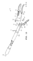
- FIG. 13 illustrates a surgical instrument coupled to a DC source and a RF source in accordance with other embodiments.
- Symmetrical control configurations often make using related art devices unintuitive.
- such controls may be moveable in a proximal direction to activate an electrode at the surgical tool, and may be moveable in a distal direction to deactivate the electrode. If the control is symmetric with respect to the directions of operation, then a user may become confused as to whether he/she is activating or deactivating the electrode.
- the exemplary embodiments help to make a control more intuitive.
- FIG. 1 illustrates a surgical instrument 9 in accordance with some embodiments.
- the surgical instrument 9 includes a handle 11 , an elongated body 13 having a proximal end 10 and a distal end 12 , and a surgical device/tool 14 located at the distal end 12 of the body 13 .
- the proximal end 10 of the elongated body 13 is coupled to a distal end 16 of the handle 11 .
- the term “surgical device” refers to any device or component that may be used to operate on tissue (e.g., to treat, manipulate, handle, hold, cut, heat, or energize, etc., tissue).
- the elongated body 13 may be rigid, or alternatively, flexible.
- the handle 11 includes an actuator 15 that is coupled to the surgical device 14 through a linkage (not shown) within a bore of the elongated body 13 for controlling an operation of the surgical device 14 .
- the handle 11 and the actuator 15 may be made from insulative material(s) such as plastic.
- the surgical device 14 includes a pair of jaws 21 , 23 for clamping, cutting, and sealing a vessel.
- the jaw 21 includes an electrically conductive material 25 which faces towards the opposing jaw 23 .
- the jaw 23 may include an electrically conductive material which faces towards jaw 21 .
- the electrically conductive material 25 is in a form of an electrode, and is configured to selectively provide heat or RF energy during use.
- the term “electrode” refers to a component that is for delivering energy, such as heat energy, RF energy, etc., and thus, should not be limited to a component that delivers any particular form of energy.
- the electrically conductive material 25 may be Ni-chrome, stainless steel, or other metals or alloys in different embodiments.
- the jaws 21 , 23 are configured to close in response to actuation (e.g., pressing, pulling, or pushing, etc.) of the actuator 15 , thereby clamping a vessel during use.
- the actuator 15 may be further actuated (e.g., further pressed, further pulled, or further pushed, etc.) to cause the electrically conductive material 25 to provide (e.g., emit) heat, thereby cutting and sealing the clamped vessel.
- the electrically conductive material 25 is electrically coupled, via a cable 29 , to a DC source 30 , which provides a current to the electrically conductive material (electrode) 25 , thereby heating the electrode 25 .
- the actuator 15 may be de-actuated to stop the delivery of current to the electrode 25 , and may be further de-actuated to open the jaws 21 , 23 .
- the mechanical linkage for translating operation of the actuator 15 into closing and opening of the jaws 21 , 23 may be implemented using cables, shafts, gears, or any of other mechanical devices that are known in the art.
- the source 30 may be other types of energy source, and need not be a DC source.
- the handle 11 also includes a plurality of electrical contact terminals 17 in respective ports 34 near the distal end 16 of the handle 11 .
- the contact terminals 17 are electrically coupled to the electrically conductive material 25 at the surgical device 14 , and are configured (e.g., shaped, sized, and positioned) for receiving RF energy from a RF source.
- each contact terminal 17 is electrically connected to the electrode 25 via electrical line that may be housed within a wall of the elongated body 13 , or that may be in a form of a cable that is housed within the bore of the elongated body 13 .
- the elongated body 13 may include an outer layer of bioinert electrically insulative material.
- the contact 17 instead of being located inside the port 34 , the contact 17 may be in a form of a ring located and exposed near the distal end 16 of the handle 11 .
- the linkage that mechanically couples the jaws 21 , 23 to the actuator 15 may be electrically insulated, for example, by silicone rubber, ceramic or other suitable non-electrically conductive material. This assures that high frequency energy supplied to the contact region 17 is conducted along the electric line housed by the body 13 to the electrically conductive material (electrode) 25 at jaw 21 (and/or electrode at jaw 23 ). In other embodiments, the body 13 may not include an electric line for coupling the contact region 17 to the electrode 25 . Instead, the linkage that mechanically couples the jaws 21 , 23 to the actuator 15 may be electrically conductive, and is used to couple RF energy received at the contact region 17 to the electrode 25 at jaw 21 (and/or electrode at jaw 23 ). For example, the linkage may be slidably coupled to the contact region 17 .
- connection ports 34 are disposed about the periphery of the handle 11 near its distal end 16 .
- Each such connection port 34 is configured to selectively receive the tip of an electrosurgical RF probe 27 , thereby allowing the respective contact terminal 17 to electrically connect such a probe 27 through the electrical line housed in the body 13 (or through the mechanical linkage, e.g., an actuating rod 36 , within the body 13 if the linkage is electrically conductive) to the electrically conductive material 25 at the distal end.
- the surgical instrument 9 allows the RF probe 27 to make contact with a terminal 17 no matter how the elongated body 13 is oriented about is longitudinal axis.
- the actuating rod 36 is mechanically linked to the actuator 15 in conventional manner to slidably translate within the elongated body 13 in response to fore and aft movements of the actuator 15 .
- Translational movement of the actuating rod 36 is linked to the jaws 21 , 23 in conventional manner to open and close the jaws in response to movement of the actuator 15 .
- providing port(s) 34 and contact terminal(s) 17 in the port(s) 34 in this exemplary configuration prevents unintentional contact of the contact terminal(s) by the user during use.
- the port(s) 34 instead of providing port(s) 34 at the handle 11 , the port(s) 34 may be provided at the elongated body 13 .
- the contact terminal 17 in the handle 11 of the surgical instrument 9 is contacted by the electrode 27 of an electrosurgical RF probe (e.g., a conventional BOVIE pencil) which is electrically coupled to a high frequency energy source (e.g., electrosurgical RF generator), through any one of the ports 34 .
- an electrosurgical RF probe e.g., a conventional BOVIE pencil
- a high frequency energy source e.g., electrosurgical RF generator
- the contact terminal 17 in each of the ports 34 allows delivering of high frequency energy from the electrosurgical RF generator to the electrosurgical RF probe, and to the electrode 25 of the surgical device 14 .
- a return monopolar RF electrode that may be in a form of a pad (not shown) is coupled to the skin of the patient, and is electrically connected to a terminal of the RF generator.
- RF energy is delivered at the electrode 25 , and is returned to the RF generator via the return monopolar RF electrode.
- the surgical instrument 9 may include an additional button (not shown) located at the handle 11 .
- the additional button may be thumb-actuated, and is configured to electrically couple the electrically conductive material 25 at the surgical device 14 to a RF source, wherein the RF source is configured to provide high frequency energy to the surgical instrument 9 (i.e., to the electrically conductive material 25 at the surgical device 14 ) via a cable.
- the surgical instrument 9 provides two modes of operation. In a first mode of operation, when the additional button is actuated, the electrically conductive material 25 is electrically coupled to the RF source, which supplies RF energy to the electrically conductive material for RF cauterization.
- the electrically conductive material 25 is electrically decoupled from the DC source 30 so that current cannot be provided to the electrically conductive material 25 from the DC source 30 for heating the electrically conductive material 25 (e.g., even if the actuator 15 is actuated).
- the electrically conductive material 25 is electrically coupled to the DC source 30 , so that the DC source 30 can supply a current to the electrically conductive material 25 for heating the electrically conductive material 25 .
- the electrically conductive material 25 is allowed to be electrically coupled to the DC source 30 by activation of the actuator 15 . In such cases, the electrically conductive material 25 is decoupled from the RF source when the additional button is deactuated, and is electrically connected to the DC source 30 upon actuation of the actuator 15 .
- first mode does not need to be associated with supplying RF energy
- second mode does not need to be associated with supplying heat energy
- first mode and second mode refer to different modes.
- the first mode of operation may be achieved by supplying heat energy
- the second mode of operation may be achieved by supplying RF energy.
- the operation of the additional button may be reversed in other embodiments. In particular, in other embodiments, actuating the additional button would enable delivery of heat energy (and disallow delivery of RF energy), and de-actuating the additional button would enable delivery of RF energy (and disallow delivery of heat energy).
- operation of the actuator 15 allows selective delivery of heat energy or RF energy in different modes of operation.
- activating the actuator 15 will result in closing of the jaw assembly.
- the activating of the actuator 15 will also configure an internal switch, which allows a current to be delivered to the conductive material 25 for providing heat, and prevents energy from the RF source from being delivered to the conductive material 25 .
- the internal switch is configured in a different way, which allows RF energy to be delivered to the conductive material 25 , and prevents energy from the DC source 30 from being delivered to the conductive material 25 .
- the internal switch will be described in further detail below with reference to FIGS. 7-10 .
- FIG. 4A illustrates the pair of jaws 21 , 23 in accordance with some embodiments.
- the electrically conductive material 25 forms a heating element (electrode) 40 that is disposed on a surface of the jaw 21 .
- the heating element 40 includes two outer portions 50 , 52 , and an inner (middle) portion 48 .
- the outer portions 50 , 52 have respective outer terminals 44 , 46 at their ends, and the middle portion 48 has an inner terminal 42 at its end.
- the portions 48 , 50 , 52 form an electrical heater circuit between the inner terminal 42 and outer terminals 44 , 46 .
- the outer portions 50 , 52 and the inner portion 48 function as an electrode that is configured to deliver heat in one mode of operation, and deliver RF energy in another mode of operation.
- the terminal 42 of the electrode 40 is electrically coupled to a first terminal of the DC source 30
- outer terminals 44 , 46 of the electrode 40 are electrically coupled to a second terminal of the DC source 30 , thereby allowing the electrode 40 to receive and conduct DC energy (e.g., for cutting and/or welding tissue).
- the electrode 40 is electrically coupled to a RF source for receiving RF energy (e.g., to provide RF cauterization for bleeding control).
- the heating element 40 may be formed using a single, flat sheet of electrically conductive material (e.g., Ni-chrome alloy, such as stainless steel at an outer layer, and Ni-chrome at an inner layer). This has reliability, manufacturing and cost advantages. It also reduces the likelihood of tissue build up and entrapment during use by minimizing crevices into which tissue can migrate.
- a distal end 41 of the heater element 40 may be disposed beyond the distal end of the jaw 21 (at the distal tip) to serve as an exposed RF monopolar electrode. This allows cauterization of tissue by RF energy to be performed using the distal tip of the jaw 21 .
- the jaw-operating mechanism and linkage of such mechanism to the actuating rod 36 may be supported in a metal housing 68 that includes metal sliding pin 70 and attachment pin 72 , all covered with an insulating layer 100 ( FIG. 4B ) of flexible material such as silicone rubber, or the like, to shield/protect adjacent tissue from moving parts and from electrical energy within the instrument. Also, such an insulating cover retains the sliding and attachment pins 70 , 72 in place to obviate the need for more expensive fasteners and mechanisms.
- current from the DC source 30 is conducted through the inner terminal 42 , and flows in the inner (middle) portion 48 of the heating element 40 and in parallel through the dual outer portions 50 , 52 of the heating element 40 to the outer terminals 44 , 46 .
- current density in the inner (middle) portion 48 is twice as high as the current density in each of the outer portions 50 , 52 in response to electrical heater signal (e.g., voltage) applied between inner terminal 42 and the outer terminals 44 , 46 .
- current densities in the inner and outer portions 48 , 50 , 52 may be altered (for example, by altering the relative widths of the heater portions, by altering resistances through selection of different materials, by altering both the widths and resistances, etc.) to alter the operating temperatures thereof in response to applied electrical heater signals.
- the outer portions 50 , 52 may operate at a temperature sufficient to weld a tissue structure (e.g., a blood vessel) grasped between the jaws 21 , 23
- the inner portion 48 may operate at a higher temperature sufficient to sever the grasped tissue structure intermediate of the welded segments.
- the heater element 40 does not receive current from the DC source 30 .
- the heater element 40 operates as a RF electrode (e.g., a monopolar electrode) and delivers RF energy that is provided from the RF generator, and that is transmitted to the heater element 40 via the contact terminal 17 .
- the application of the RF energy may be used to control bleeding in surrounding tissues at the surgical site, e.g., tissue that is next to the vessel being harvested, or tissue next to a side branch vessel, etc.
- the jaw 21 includes a structural support 64
- the jaw 23 includes a structural support 66 .
- the structural supports 64 , 66 may be made from electrically conductive material that allows the supports 64 , 66 to function as electrical lines (e.g., for transmitting current, RF signal, etc.).
- the structural supports 64 , 66 are covered by respective layers of electrically insulating material, such as rubber, polymers, silicone, polycarbonate, ceramic or other suitable insulating material. The layers may be molded separately and bonded onto the respective structural supports 64 , 66 .
- the layers may be over-molded onto the structural supports 64 , 66 .
- each of the structural supports 64 , 66 may have one or more openings for allowing the material of the respective layers to flow therethrough during the over-molding process.
- the jaw 23 includes a surface elevation (protrusion) 54 substantially in alignment with the inner (middle) portion 48 in order to increase the compression force applied to a tissue structure grasped by the jaws 21 , 23 and in contact with the middle portion 48 . This promotes more efficient tissue severance, while adjacent regions 56 , 58 of lower surface elevations on jaw 23 in alignment with the outer portions 50 , 52 of the heating element introduce less compression force suitable for welding grasped tissue.
- the cross sections of the respective jaws 21 , 23 are not symmetrical. Instead, jaw 21 has a protrusion 60 , and jaw 23 has a protrusion 62 .
- Each of the protrusions 60 , 62 has a length so that when the protrusions 60 , 62 abut against a main vessel 142 , the cutting point of the side branch vessel 140 is at a prescribed (predetermined) distance D that is spaced away from the main vessel 142 ( FIG. 5B ).
- the distance D is at least 1 mm, and more preferably, at least 1.5 mm.
- the distance D may have other values, such as that which is sufficient to prevent or minimize thermal spread from electrode 40 to the main vessel 142 being harvested.
- the protrusions 60 , 62 help prevent or minimize thermal spread to the main vessel 142 from the cutting and sealing of the side branch vessel 140 , thereby preserving the integrity of the main vessel 142 that is being harvested. Also, the protrusions 60 , 62 obviate the need for an operator to guess whether the cutting of the side branch vessel 140 is sufficiently far (e.g., beyond a minimum prescribed spacing) from the main vessel 142 .
- the operator merely abuts the protrusions 60 , 62 of the jaw assembly against the main vessel 142 , and the protrusions 60 , 62 will automatically place the jaw assembly relative to the side branch vessel 140 so that the side branch vessel 140 is cut at a minimum prescribed distance D from the main vessel 142 .
- the protrusions 60 , 62 also provide the same benefits of preserving the integrity of tissue adjacent to the cut, and obviating the need for a user to guess the appropriate margin. As shown in the figure, the protrusions 60 , 62 diverge away from part of the side branch vessel 140 .
- the surgical instrument 9 does not need to include both protrusions 60 , 62 . Instead, the surgical instrument 9 may include either protrusion 60 or protrusion 62 . Such a configuration allows the device at the distal end of the instrument 9 to have a smaller profile, thereby allowing a user to effectively maneuver the distal device in tight tissue conditions.
- the outer portion 52 may protrude laterally along an outer edge of the closed jaws 21 , 23 to serve as an RF electrode for RF signal applied thereto, in a manner described herein, while the outer portion 50 is shrouded or recessed within the lateral protrusions 60 , 62 on the jaws 21 , 23 to limit emission of applied RF signal from along mainly (or only) the exposed edge of the outer portion 52 .
- the jaw assembly has a concave side 130 and a convex side 132 .
- the jaw assembly is oriented so that its concave side faces towards the main vessel 142 .
- An endoscope or viewing device may be placed next to the jaw assembly with the endoscope or viewing device viewing the concave side of the jaw assembly. This allows the user to better visualize the tip of the jaw assembly. Such configuration also provides a safety benefit by allowing the user to know where the tips are during the vessel cutting procedure. Also as shown in FIG.
- the exposed outer portion 52 is on the convex side of the jaw assembly while the protrusions 60 , 62 are on the concave side of the jaw assembly.
- the concavity provides extra spacing to further protect the main vessel 142 when the side branch vessel 140 is grasped.
- the exposed outer portion 52 on the convex side creates a protrusion that makes it easier to contact the wall of the tunnel with the exposed outer portion 52 to address bleeding.
- the protrusions 60 , 62 may be on the convex side of the jaw assembly while the exposed outer portion 52 is on the concave side.
- the convex side of the jaw assembly would be oriented towards the main vessel 142 , thereby ensuring that the tips of the jaw assembly are separated from the main vessel 142 to enhance protection (e.g., preventing the tip of the jaw assembly from touching or injuring the main vessel 142 ).
- FIGS. 7A and 7B shows some of the interior components of the handle 11 .
- an electrical switch 78 is mounted in the handle 11 to be operated in conjunction with the actuator 15 (not shown in FIG. 7A for clarity) for controlling electrical power supplied to the inner and outer portions 48 , 50 , 52 .
- the actuator 15 is rotatably mounted to the handle 11 via a shaft 89 so that the actuator 15 is pivotable about axis 90 .
- the actuator 15 is located next to the electrical switch 78 in a side-by-side configuration. As shown in FIG.
- the actuator 15 has a tab portion 92 for engagement with a lever 94 of the switch 78 .
- the switch 78 has a first contact (common contact) 95 , a second contact (normally-open contact) 96 , and a third contact (normally-closed contact) 97 .
- the first contact 95 is electrically connected to a terminal of the heating element (electrode) 40 (e.g., via a wire), and the second contact 96 is electrically connected to a first terminal of the DC source 30 ( FIG. 10 ).
- Another terminal of the heating element (electrode) 40 is electrically connected to a second terminal of the DC source 30 ( FIG. 10 ). As shown in FIG.
- At least two wires can be used to connect the first terminal of the DC source 30 to the second contact 96 at the switch 78 , and at least two wires can be used to connect the second terminal of the source 30 to a fuse 99 that is coupled to the electrode 40 .
- the fuse 99 is a safety device for preventing overheating of the surgical instrument 9 . In some embodiments, if the heating circuit's temperature is above a certain prescribed threshold, the fuse 99 will prevent a current from being delivered to the electrode 40 . Having two wires for each terminal of the DC source 30 is provides redundancy, so that switch 78 functions even if one of the wires for any of the terminals at the DC source 30 is broken.
- the surgical instrument 9 may include only one wire connecting terminal 96 to the source 30 , and only one wire connecting the fuse 99 to the source 30 .
- a contact device 74 is electrically connected to the third contact 97 of the electric switch 78 .
- the contact device 74 is used to implement the contact terminal(s) 17 .
- Electrical switches that may be used with the handle 11 are commercially available from E-Switch, at Brooklyn Park, Minn.
- the handle assembly 11 is completed with a complementary half section (not shown) that snaps together with, or is otherwise attached to the illustrated half section.
- the handle 11 is formed of plastic material that also provides electrical insulation from RF emissions while the surgical instrument 9 is connected with the RF generator in the manner as previously describe herein. In some cases, the material for construction of the handle 11 is selected so that it provides adequate strength for the handle 11 to withstand forces of the mechanisms and forces of the user interacting with the instrument during a procedure.
- the actuator 15 has a button 150 with a distal portion 152 and a proximal portion 154 .
- the actuator 15 also has a body 156 extending from the button 150 to an end 158 with a slot 160 for accommodating a shaft.
- the actuator 15 further includes a spring lever 162 having a free end 164 , and is connected to the body 156 via a bent end 166 .
- the free end 164 of the lever 162 has a protrusion 168 for engaging with a corresponding portion at the housing of the handle 11 .
- the spring lever 162 also has a tab portion 92 for engagement with the lever 94 of the electrical switch 78 during use. As shown in FIG.
- the protrusion 168 is configured to engage the detent portion 172 first before the tab portion 92 fully activates the switch 78 .
- the user will feel a resistance when the protrusion 168 engages with the detent portion 172 at the handle 11 .
- the user may then continue to pull the actuator 15 proximally with an increase of pulling force.
- the increased pulling force will cause the detent portion 172 to deflect the spring lever 162 downward, until the protrusion 168 traverses the detent portion 172 ; at this point, the user will feel a decrease in pulling force.
- the actuator 15 is allowed to be pulled proximally further, thereby causing the tab portion 92 to deflect the lever 94 of the switch 78 .
- all of the components of the actuator 15 have a unity construction except for the over-molded piece 20 on button 150 .
- Such configuration obviates the need to mechanically connect the different components together, and reduces manufacturing costs.
- the material connecting the spring lever 162 to the body 156 of the actuator 15 will function as a joint and spring, thereby obviating the need to provide a separate connector for connecting the lever 162 to the body 156 , and a separate spring element (e.g., a coil) for providing the resiliency for the lever 162 .
- FIGS. 9B-9D illustrate respectively side, distal and perspective views of the actuator 15 without the over-molded piece 20 disposed on button base 38 .
- FIGS. 9E-9G respectively illustrate bottom, distal and top views of the over-molded piece.
- FIG. 9E illustrates an exemplary cavity 35 created by the over-molding process, inside of which fits button base 38 .
- all of the components of the actuator 15 including button 150 have a unity construction.
- the distal portion 152 of the actuator 15 has a concave configuration
- the proximal portion 154 of the actuator 15 has a convex configuration.
- a user may place his/her finger in the recess of the concave surface at the distal portion 152 , and pull the actuator 15 proximally relative to the handle 11 .
- the pulling of the actuator 15 causes the jaw assembly at the distal end to close and activates the electrode 25 at the distal end of the surgical instrument 9 .
- the user may also place his/her finger at the convex surface at the proximal portion 154 , and push the actuator 15 distally relative to the handle 11 .
- pushing the actuator 15 distally causes the jaw assembly at the distal end to open and deactivates the electrode 25 .
- the actuator 15 and the mechanism inside the handle 11 may be configured to produce the opposite effects.
- pushing the actuator 15 distally may cause the jaw assembly at the distal end to close and may activate the electrode 25 at the distal end of the surgical instrument 9
- pulling the actuator 15 proximally may cause the jaw assembly to open and may deactivate the electrode 25 .
- the asymmetric configuration of the button 150 of the actuator 15 provides an intuitive interface for allowing the user to control the actuator 15 .
- the actuator 15 is configured to close the jaw assembly and activate the electrode 25 when the actuator 15 is pulled proximally relative to the handle 11 , then the user will know that he/she is closing the jaw assembly and/or activating the electrode 25 as soon as he/she places the finger in the concave surface at the distal portion 152 of the button 150 .
- the user will also know that he/she is opening the jaw assembly and/or deactivating the electrode 25 as soon as he/she places the finger on the convex surface at the proximal portion 154 of the button 150 . This is because the different configurations at the distal and proximal portions 152 , 154 provide different tactile information to the user, thereby informing the user of the different modes of operation of the actuator 15 .
- a compression spring 180 (shown in FIG. 7B ) may be used to bias the actuator 15 in a distal direction.
- the user When pulling back on the actuator 15 , the user has to overcome the resistance of both the detent portion 172 and the spring 180 .
- the user when pushing the actuator 15 distally, the user may receive assistance from the spring 180 because the spring 180 is under compression. As a result, the user may feel different resistances to motion, depending on whether he/she is pulling or pushing the actuator 15 .
- the button 150 of the actuator 15 may have different types of asymmetric configurations.
- the distal portion 152 may have a surface with a first type of texture (e.g., bumps), and the proximal portion 154 may have a surface with a second type of texture (e.g., no bumps) that is different from the first type.
- the distal portion 152 may be made from a first material
- the proximal portion 154 may be made from a second material that is different from the first material (e.g., softer, stiffer, more compliant, less compliant, etc.).
- Such configuration either along, or in combination with the spring 180 and detent portion 172 , provides the actuator 15 with a first resistance to motion when the actuator 15 is operated in one way, and a second resistance to motion that is different from the first resistance when the actuator 15 is operated in another way.
- any of the configurations of the distal and proximal portions 152 , 154 may be reversed.
- the distal portion 152 may have a convex configuration
- the proximal portion 154 may have a concave configuration.
- the protrusion 168 may have an asymmetric configuration to provide different “feels” for the user when the user is pulling and pushing the actuator 15 .
- the ramp may be steeper on one side of the protrusion 168 than the other.
- the actuator 15 may be harder to pull proximally than to push distally.
- the distal and proximal portions 152 , 154 are both made from compliant materials, but with different degrees of compliance. Such a control would be more comfortable to use than a control that is made from a hard plastic (a non-compliant material).
- the contact terminals 17 are implemented using a resilient electrical contact device 74 that is disposed within the handle 11 .
- the contact device 74 includes a plurality of resilient contact terminals 17 (each of which may be considered a contact region) that are aligned with respective connection ports 34 .
- Each port 34 allows access by a RF probe, such as a conventional BOVIE pencil, for making contact with the corresponding contact terminal 17 therein.
- a smoke filter 76 is positioned in the forward end of the handle 11 .
- the filter 76 is for filtering steam/smoke generated during operation of the device (e.g., steam/smoke that results from cutting tissue, welding tissue, and/or bleeding control) so that the steam/smoke will not interfere with the user of the surgical instrument 9 , to help improve visualization in the working site, and to reduce the amount of surgical smoke that is introduced into the operating environment.
- the working tunnel has a pressure differential caused by pressurized gas (e.g., CO 2 ) such that smoke is forced from the tunnel into the device tip, through the interior of the elongated body 13 , and into the filter 76 of the handle 11 .
- the actuating rod 36 is mechanically linked in conventional manner to the actuator 15 to slidably translate the actuating rod 36 within the elongated body 13 for remotely operating the jaws 21 , 23 between open and closed positions.
- the actuator 15 when the actuator 15 is pushed forward (by rotating about axis 90 ) to push actuating rod 36 , the translational motion of the actuating rod 36 causes the jaws 21 , 23 to open. The opened jaws 21 , 23 can then be used to grasp tissue (e.g., side branch vessel). When the jaws 21 , 23 are placed around target tissue, the actuator 15 may be pulled backward to pull actuating rod 36 . The translational motion of the actuating rod 36 causes the jaws 21 , 23 to close, thereby gripping the target tissue. If desired, the actuator 15 may be further pulled backward to cause the tab portion 92 of the actuator 15 to engage the lever 94 of the electrical switch 78 .
- tissue e.g., side branch vessel
- the contact device 74 will not be able to transmit RF energy (e.g., from an electrosurgical RF probe) to the electrode 40 .
- the delivery of DC energy may be stopped by pushing the actuator 15 forward so that the tab portion 92 is disengaged from the lever 94 of the electrical switch 78 .
- the second contact 96 is electrically disconnected from the first contact 95 inside the switch 78
- the third contact 97 is electrically connected to the first contact 95 inside the switch 78 .
- RF energy from the electrosurgical RF probe delivered at the contact device 74 and transmitted to the third contact 97
- DC energy cannot be delivered to the electrode 40 because the first and second contacts of the switch 78 are not electrically connected.
- FIG. 11 there is illustrated an exploded view of the components forming the surgical device 14 , and its attachment to the distal end of the elongated body 13 .
- the heating element 40 comprising inner and outer portions 48 , 50 , 52 (conductive material 25 ) is attached to jaw 21 .
- Both jaws 21 , 23 are pivotally attached via insulating material clevises 85 and 87 and pin 77 to the metal housing 68 .
- the jaws 21 , 23 pivot on the clevises 85 , 87 so that they can be kept electrically isolated from pin 77 which holds inner terminal 42 against the face of jaw 21 .
- Pin 70 is disposed to slide within the aligned slots 79 , and within the mating angled slots 81 , 83 in the frame-mounts of the associated jaws to effect scissor-like jaw movement between open and closed positions as the slide pin 70 is moved relative to the pivot pin 77 .
- Actuating rod 36 is linked to the slide pin 70 , for example, via a yoke 37 that is attached to the distal end of the actuator rod 36 . Axial movement of the actuating rod 36 in one direction will cause the slide pin 70 to move towards the pin 77 , thereby opening the jaws 21 , 23 .
- Axial movement of the actuating rod 36 in the opposite direction will cause the slide pin 70 to move away from the pin 77 , thereby closing the jaws 21 , 23 .
- An electrical conductor 89 connects to the inner terminal 42 of the heating element 40 , and the outer terminals 44 , 46 are electrically connected in common to electrical conductor 91 .
- either electrical conductor 89 or 91 may be housed within the wall or the bore of the elongated body 13 .
- either electrical conductor 89 or 91 may be coupled to the actuating rod 36 .
- the actuating rod 36 will be electrically coupled to one terminal of the DC source 30 , or to the contact 95 of the switch 78 , during use.
- the electrical conductors 89 , 91 may be electrically coupled to terminals of the DC source 30 , which provides a current to thereby heat up the inner and outer portions 48 , 50 , 52 of the heating element 40 .
- the center inner portion 48 is configured to cut a vessel (e.g., a side branch vessel) while the outer portions 50 , 52 are configured to weld (seal) the vessel.
- parts of the surgical device 14 may be insulated via an outer insulating layer for restricting RF emissions (when the bleeding control function is used) and for isolating certain components from biologic tissue and fluids.
- the surgical instrument 9 includes an insulative cover 100 .
- the elongated body 13 is advanced along a vessel to be harvested.
- the instrument 9 may be placed into an instrument channel of a cannula which includes a viewing device, such as an endoscope, for allowing an operator to see the distal end of the surgical instrument 9 inside the patient.
- a viewing device such as an endoscope
- the jaws 21 , 23 may be used to grasp and compress the side-branch vessel in response to manipulation of the actuator 15 .
- Power is then supplied using the DC source 30 to the inner and outer portions 48 , 50 , 52 of the heating element 40 (which function as resistive elements that heat up in response to the delivered direct current) to effect tissue welds at tissues that are in contact with outer portions 50 , 52 , and to effect tissue cutting at tissue that is in contact with inner portion 48 .
- the operator may position the electrosurgical RF probe 27 so that it is in contact with the contact terminal 17 through one of the ports 34 at the handle 11 . This results in RF energy being supplied (or allowed to be supplied) from the attached electrosurgical RF generator.
- a foot-actuated switch may be provided that allows the operator to direct RF energy from the RF generator to the RF probe 27 .
- the supplied RF energy from the RF generator is conducted to the electrically conductive material 25 at the distal surgical device 14 , and the energy is returned via a return electrode pad that is coupled to the skin of the patient.
- the electrically conductive material 25 serves as a monopole RF electrode to electrocauterize any tissue (e.g., vessel tissue or surrounding tissue) that is grasped between the jaws 21 , 23 .
- tissue e.g., vessel tissue or surrounding tissue
- the lateral edge of the outer portion 52 that protrudes from a side of the jaw 21 may be used to cauterize bleeding area.
- the jaws 21 , 23 may or may not be closed, and may or may not be grasping any tissue.
- the operator may not be using the jaws 21 , 23 to grasp or cut tissue.
- the operator may use the outer portion 52 protruding from a side of the jaw 21 (e.g., such as that shown in FIG. 6 ) to cauterize the bleeding area.
- the exposed portion of outer portion 52 serves as an RF monopole electrode for electrocauterizing the tissue.
- the exposed portion of the outer portion 52 may also be used as a DC electrode for controlling bleeding.
- the side or the tip of the outer portion 52 that extends beyond the profile of the jaw assembly may be used to perform thermal spot cauterization by direct thermal conduction.
- the outer portion 52 may be heated up, and its exposed edge (or tip) may be used to touch tissue that is desired to be cauterized.
- the surgical instrument 9 has been described as having contact terminal(s) for allowing a RF probe to make contact, thereby causing the surgical instrument 9 to deliver RF energy at its distal end.
- the surgical instrument 9 may be configured to deliver RF energy without using any RF probe to make contact with it.
- the surgical instrument 9 may be coupled to the DC source 30 via a cable 200 , wherein the cable 200 is for delivering DC energy from the DC source 30 to the surgical instrument 9 ( FIG. 12 ).
- the cable 200 also includes circuitry for receiving RF energy from a RF source 220 that is coupled to the DC source, as shown in the figure.
- the DC source 30 is configured to transmit DC energy to the surgical instrument 9 via the DC lines 144 .
- the DC source 30 is configured to allow RF source 220 to transmit RF energy to the surgical instrument 9 via the RF line 146 .
- the DC source 30 may include a switch for switching between two modes of operation. Alternatively, the switch may be implemented at any point along the length of the cable 200 or at the handle 11 .
- a RF control such as a button, a foot pedal, etc., may be provided, for allowing a user to direct RF energy to the surgical instrument 9 .
- the RF control may be coupled to the RF source 220 , to the DC source 30 , or at any point along the RF line. In other embodiments, the RF control may also be implemented as a component at the RF source 220 , at the DC source 30 , or at the cable 200 .
- the cable 200 may be coupled to a switch box 210 .
- the switch box 210 is configured to receive energy from the DC source 30 and transmit it to the surgical instrument 9 in one mode of operation ( FIG. 13 ). In another mode of operation, the switch box 210 is configured to receive RF energy from a RF source 220 , and transmit the RF energy to the surgical instrument 9 .
- the switch box 210 may include a control for allowing a user to switch between the first and second modes of operation. Alternatively, the control for switching between modes of operation may be implemented at any point along the length of the cable 200 or at the handle 11 .
- a RF control such as a button, a foot pedal, etc., may be provided, for allowing a user to direct RF energy to the surgical instrument 9 .
- RF energy will not be delivered unless the RF control is actuated by the user.
- the RF control may be coupled to the RF source 220 , the switch box 210 , or to any point along the length of the cable 200 .
- the RF control may also be implemented as a component at the RF source 220 , at the switch box 210 , or at the cable 200 .
- the surgical instrument 9 allows delivery of heat to a remote surgical site for welding and severing vessel, and allows delivery of RF energy for cauterizing tissue to control bleeding.
- Such an instrument combines a heat delivery function with a RF delivery function to allow a user to address two very different situations (e.g., tissue welding and bleeding control) using a single tool.
- many of the components in the surgical instrument 9 that are for providing DC heating are also used for delivering RF energy, operative portion of the surgical instrument 9 maintains a low profile, without any increase in size due to its dual capability.
- the surgical instrument 9 allows delivery of RF energy in a controlled manner, thereby protecting the vessel being harvested while allowing bleeding to be controlled.
- Embodiments of the surgical instrument 9 also obviate the need for repeatedly inserting a separate bleeding control device inside the patient to control bleeding, and removing such bleeding control device from the patient, during a vessel harvesting procedure.
- embodiments of the surgical instrument 9 described herein allow delivery of RF energy in a way that makes it much easier and more efficient to address bleeding.
- the surgical device 14 may have different configurations, and different functionalities.
- the surgical device 14 may be clip appliers or grasping jaws with no heating functionality, but still include one or more high frequency electrodes for delivering RF energy from RF source to control bleeding.
- the bleeding control feature e.g., the components for allowing RF to be delivered to the distal end of the surgical instrument
- the surgical instrument 9 may be used in any endoscopic procedure that requires dissection or transection of tissue with bleeding control.
- the surgical instrument 9 may be configured to deliver heat energy and RF energy simultaneously.
- the surgical instrument 9 may include an electrode for delivering heat energy to cut and/or seal tissue, and another electrode for delivering RF energy for bleeding control.
- the surgical instrument 9 may include an operative element for simultaneously delivering heat and RF energy.
- the surgical instrument 9 may not include the port(s) 34 , the contact terminal(s) 17 , and the electrical switch 78 .
- the jaw assembly at the distal end of the surgical instrument 9 does not need to include all of the features described herein.
- the jaw assembly does not include outer electrode portions 50 , 52 .
- the jaw assembly includes one electrode strip (comparable to the middle electrode portion 48 described above) for cutting or sealing tissue.
- the jaw 23 may not have the surface elevation 54 .
- the jaw 23 may have a flat surface that is for contacting the inner and outer electrode portions 48 , 50 , 52 .
- the jaws 21 , 23 may not include the respective protrusions 60 , 62 .
- the cross section of the jaw 21 / 23 may have a symmetrical configuration.
- protrusion(s) may be provided on both sides of the jaw assembly (e.g., one or more protrusions at the concave side of the jaw assembly, and one or more protrusions at the convex side of the jaw assembly).
- Such configuration provides buffering on both sides of the jaw assembly, and allows for correct placement of the jaw assembly regardless of which side (the concave or convex side) of the jaw assembly is oriented towards the main vessel 142 during use.
- the jaws could be straight.
- the electrode 40 instead of, or in addition to, using the electrode 40 for controlling bleeding, the electrode 40 may be used for dissection or transection of tissue, such as fatty and connective tissue encountered during a vessel harvesting procedure.
Abstract
Description
Claims (27)
Priority Applications (4)
| Application Number | Priority Date | Filing Date | Title |
|---|---|---|---|
| US13/094,795 US9402680B2 (en) | 2008-05-27 | 2011-04-26 | Surgical instrument and method |
| US15/225,753 US20160338766A1 (en) | 2008-05-27 | 2016-08-01 | Surgical instrument and method |
| US15/618,112 US10973568B2 (en) | 2008-05-27 | 2017-06-08 | Surgical instrument and method |
| US17/222,958 US20210220041A1 (en) | 2008-05-27 | 2021-04-05 | Surgical instrument and method |
Applications Claiming Priority (4)
| Application Number | Priority Date | Filing Date | Title |
|---|---|---|---|
| US5620708P | 2008-05-27 | 2008-05-27 | |
| US12/472,657 US9402679B2 (en) | 2008-05-27 | 2009-05-27 | Surgical instrument and method |
| US32779810P | 2010-04-26 | 2010-04-26 | |
| US13/094,795 US9402680B2 (en) | 2008-05-27 | 2011-04-26 | Surgical instrument and method |
Related Parent Applications (1)
| Application Number | Title | Priority Date | Filing Date |
|---|---|---|---|
| US12/472,657 Continuation-In-Part US9402679B2 (en) | 2008-05-27 | 2009-05-27 | Surgical instrument and method |
Related Child Applications (1)
| Application Number | Title | Priority Date | Filing Date |
|---|---|---|---|
| US15/225,753 Continuation US20160338766A1 (en) | 2008-05-27 | 2016-08-01 | Surgical instrument and method |
Publications (2)
| Publication Number | Publication Date |
|---|---|
| US20110288369A1 US20110288369A1 (en) | 2011-11-24 |
| US9402680B2 true US9402680B2 (en) | 2016-08-02 |
Family
ID=44973030
Family Applications (4)
| Application Number | Title | Priority Date | Filing Date |
|---|---|---|---|
| US13/094,795 Active 2032-10-28 US9402680B2 (en) | 2008-05-27 | 2011-04-26 | Surgical instrument and method |
| US15/225,753 Abandoned US20160338766A1 (en) | 2008-05-27 | 2016-08-01 | Surgical instrument and method |
| US15/618,112 Active 2030-12-17 US10973568B2 (en) | 2008-05-27 | 2017-06-08 | Surgical instrument and method |
| US17/222,958 Pending US20210220041A1 (en) | 2008-05-27 | 2021-04-05 | Surgical instrument and method |
Family Applications After (3)
| Application Number | Title | Priority Date | Filing Date |
|---|---|---|---|
| US15/225,753 Abandoned US20160338766A1 (en) | 2008-05-27 | 2016-08-01 | Surgical instrument and method |
| US15/618,112 Active 2030-12-17 US10973568B2 (en) | 2008-05-27 | 2017-06-08 | Surgical instrument and method |
| US17/222,958 Pending US20210220041A1 (en) | 2008-05-27 | 2021-04-05 | Surgical instrument and method |
Country Status (1)
| Country | Link |
|---|---|
| US (4) | US9402680B2 (en) |
Cited By (118)
| Publication number | Priority date | Publication date | Assignee | Title |
|---|---|---|---|---|
| USD782675S1 (en) * | 2015-04-23 | 2017-03-28 | Gyrus Acmi, Inc. | Drill handle |
| US9610113B2 (en) | 2005-03-25 | 2017-04-04 | Maquet Cardiovascular Llc | Apparatus and method for regulating tissue welder jaws |
| US9636163B2 (en) | 2005-03-25 | 2017-05-02 | Maquet Cardiovascular Llc | Tissue welding and cutting apparatus and method |
| USD788301S1 (en) * | 2015-04-23 | 2017-05-30 | Gyrus Acmi Inc | Drill |
| USD792592S1 (en) * | 2015-04-23 | 2017-07-18 | Gyrus Acmi, Inc. | Angled drill |
| USD803396S1 (en) * | 2015-12-10 | 2017-11-21 | Ethicon Llc | Handle for an endoscopic surgical instrument |
| US9955858B2 (en) | 2009-08-21 | 2018-05-01 | Maquet Cardiovascular Llc | Surgical instrument and method for use |
| US9968396B2 (en) | 2008-05-27 | 2018-05-15 | Maquet Cardiovascular Llc | Surgical instrument and method |
| US10117667B2 (en) | 2010-02-11 | 2018-11-06 | Ethicon Llc | Control systems for ultrasonically powered surgical instruments |
| US10154852B2 (en) | 2015-07-01 | 2018-12-18 | Ethicon Llc | Ultrasonic surgical blade with improved cutting and coagulation features |
| US10179022B2 (en) | 2015-12-30 | 2019-01-15 | Ethicon Llc | Jaw position impedance limiter for electrosurgical instrument |
| US10194973B2 (en) | 2015-09-30 | 2019-02-05 | Ethicon Llc | Generator for digitally generating electrical signal waveforms for electrosurgical and ultrasonic surgical instruments |
| US10201382B2 (en) | 2009-10-09 | 2019-02-12 | Ethicon Llc | Surgical generator for ultrasonic and electrosurgical devices |
| US10226273B2 (en) | 2013-03-14 | 2019-03-12 | Ethicon Llc | Mechanical fasteners for use with surgical energy devices |
| US10245064B2 (en) | 2016-07-12 | 2019-04-02 | Ethicon Llc | Ultrasonic surgical instrument with piezoelectric central lumen transducer |
| US10245065B2 (en) | 2007-11-30 | 2019-04-02 | Ethicon Llc | Ultrasonic surgical blades |
| US10251664B2 (en) | 2016-01-15 | 2019-04-09 | Ethicon Llc | Modular battery powered handheld surgical instrument with multi-function motor via shifting gear assembly |
| USD847990S1 (en) | 2016-08-16 | 2019-05-07 | Ethicon Llc | Surgical instrument |
| US10278721B2 (en) | 2010-07-22 | 2019-05-07 | Ethicon Llc | Electrosurgical instrument with separate closure and cutting members |
| US10285723B2 (en) | 2016-08-09 | 2019-05-14 | Ethicon Llc | Ultrasonic surgical blade with improved heel portion |
| US10285724B2 (en) | 2014-07-31 | 2019-05-14 | Ethicon Llc | Actuation mechanisms and load adjustment assemblies for surgical instruments |
| US10299810B2 (en) | 2010-02-11 | 2019-05-28 | Ethicon Llc | Rotatable cutting implements with friction reducing material for ultrasonic surgical instruments |
| US10321950B2 (en) | 2015-03-17 | 2019-06-18 | Ethicon Llc | Managing tissue treatment |
| US10335183B2 (en) | 2012-06-29 | 2019-07-02 | Ethicon Llc | Feedback devices for surgical control systems |
| US10335182B2 (en) | 2012-06-29 | 2019-07-02 | Ethicon Llc | Surgical instruments with articulating shafts |
| US10335614B2 (en) | 2008-08-06 | 2019-07-02 | Ethicon Llc | Devices and techniques for cutting and coagulating tissue |
| US10342602B2 (en) | 2015-03-17 | 2019-07-09 | Ethicon Llc | Managing tissue treatment |
| US10349999B2 (en) | 2014-03-31 | 2019-07-16 | Ethicon Llc | Controlling impedance rise in electrosurgical medical devices |
| US10357303B2 (en) | 2015-06-30 | 2019-07-23 | Ethicon Llc | Translatable outer tube for sealing using shielded lap chole dissector |
| US10376305B2 (en) | 2016-08-05 | 2019-08-13 | Ethicon Llc | Methods and systems for advanced harmonic energy |
| US10398466B2 (en) | 2007-07-27 | 2019-09-03 | Ethicon Llc | Ultrasonic end effectors with increased active length |
| US10420579B2 (en) | 2007-07-31 | 2019-09-24 | Ethicon Llc | Surgical instruments |
| US10420580B2 (en) | 2016-08-25 | 2019-09-24 | Ethicon Llc | Ultrasonic transducer for surgical instrument |
| US10426507B2 (en) | 2007-07-31 | 2019-10-01 | Ethicon Llc | Ultrasonic surgical instruments |
| US10433900B2 (en) | 2011-07-22 | 2019-10-08 | Ethicon Llc | Surgical instruments for tensioning tissue |
| US10441308B2 (en) | 2007-11-30 | 2019-10-15 | Ethicon Llc | Ultrasonic surgical instrument blades |
| US10441310B2 (en) | 2012-06-29 | 2019-10-15 | Ethicon Llc | Surgical instruments with curved section |
| US10441345B2 (en) | 2009-10-09 | 2019-10-15 | Ethicon Llc | Surgical generator for ultrasonic and electrosurgical devices |
| US10456193B2 (en) | 2016-05-03 | 2019-10-29 | Ethicon Llc | Medical device with a bilateral jaw configuration for nerve stimulation |
| USD865964S1 (en) | 2017-01-05 | 2019-11-05 | Ethicon Llc | Handle for electrosurgical instrument |
| US10463421B2 (en) | 2014-03-27 | 2019-11-05 | Ethicon Llc | Two stage trigger, clamp and cut bipolar vessel sealer |
| US10485607B2 (en) | 2016-04-29 | 2019-11-26 | Ethicon Llc | Jaw structure with distal closure for electrosurgical instruments |
| US10517627B2 (en) | 2012-04-09 | 2019-12-31 | Ethicon Llc | Switch arrangements for ultrasonic surgical instruments |
| US10524872B2 (en) | 2012-06-29 | 2020-01-07 | Ethicon Llc | Closed feedback control for electrosurgical device |
| US10524854B2 (en) | 2010-07-23 | 2020-01-07 | Ethicon Llc | Surgical instrument |
| US10531910B2 (en) | 2007-07-27 | 2020-01-14 | Ethicon Llc | Surgical instruments |
| US10537352B2 (en) | 2004-10-08 | 2020-01-21 | Ethicon Llc | Tissue pads for use with surgical instruments |
| US10543008B2 (en) | 2012-06-29 | 2020-01-28 | Ethicon Llc | Ultrasonic surgical instruments with distally positioned jaw assemblies |
| US10555769B2 (en) | 2016-02-22 | 2020-02-11 | Ethicon Llc | Flexible circuits for electrosurgical instrument |
| US10575892B2 (en) | 2015-12-31 | 2020-03-03 | Ethicon Llc | Adapter for electrical surgical instruments |
| US10595930B2 (en) | 2015-10-16 | 2020-03-24 | Ethicon Llc | Electrode wiping surgical device |
| US10595929B2 (en) | 2015-03-24 | 2020-03-24 | Ethicon Llc | Surgical instruments with firing system overload protection mechanisms |
| US10603064B2 (en) | 2016-11-28 | 2020-03-31 | Ethicon Llc | Ultrasonic transducer |
| US10639092B2 (en) | 2014-12-08 | 2020-05-05 | Ethicon Llc | Electrode configurations for surgical instruments |
| US10646269B2 (en) | 2016-04-29 | 2020-05-12 | Ethicon Llc | Non-linear jaw gap for electrosurgical instruments |
| US10688321B2 (en) | 2009-07-15 | 2020-06-23 | Ethicon Llc | Ultrasonic surgical instruments |
| US10702329B2 (en) | 2016-04-29 | 2020-07-07 | Ethicon Llc | Jaw structure with distal post for electrosurgical instruments |
| US10709906B2 (en) | 2009-05-20 | 2020-07-14 | Ethicon Llc | Coupling arrangements and methods for attaching tools to ultrasonic surgical instruments |
| US10716615B2 (en) | 2016-01-15 | 2020-07-21 | Ethicon Llc | Modular battery powered handheld surgical instrument with curved end effectors having asymmetric engagement between jaw and blade |
| US10722261B2 (en) | 2007-03-22 | 2020-07-28 | Ethicon Llc | Surgical instruments |
| US10729494B2 (en) | 2012-02-10 | 2020-08-04 | Ethicon Llc | Robotically controlled surgical instrument |
| USD895112S1 (en) | 2018-11-15 | 2020-09-01 | Ethicon Llc | Laparoscopic bipolar electrosurgical device |
| US10765470B2 (en) | 2015-06-30 | 2020-09-08 | Ethicon Llc | Surgical system with user adaptable techniques employing simultaneous energy modalities based on tissue parameters |
| US10779848B2 (en) | 2006-01-20 | 2020-09-22 | Ethicon Llc | Ultrasound medical instrument having a medical ultrasonic blade |
| US10779879B2 (en) | 2014-03-18 | 2020-09-22 | Ethicon Llc | Detecting short circuits in electrosurgical medical devices |
| US10779845B2 (en) | 2012-06-29 | 2020-09-22 | Ethicon Llc | Ultrasonic surgical instruments with distally positioned transducers |
| US10820920B2 (en) | 2017-07-05 | 2020-11-03 | Ethicon Llc | Reusable ultrasonic medical devices and methods of their use |
| US10828059B2 (en) | 2007-10-05 | 2020-11-10 | Ethicon Llc | Ergonomic surgical instruments |
| US10828057B2 (en) | 2007-03-22 | 2020-11-10 | Ethicon Llc | Ultrasonic surgical instruments |
| US10835768B2 (en) | 2010-02-11 | 2020-11-17 | Ethicon Llc | Dual purpose surgical instrument for cutting and coagulating tissue |
| US10835307B2 (en) | 2001-06-12 | 2020-11-17 | Ethicon Llc | Modular battery powered handheld surgical instrument containing elongated multi-layered shaft |
| US10842580B2 (en) | 2012-06-29 | 2020-11-24 | Ethicon Llc | Ultrasonic surgical instruments with control mechanisms |
| US10842522B2 (en) | 2016-07-15 | 2020-11-24 | Ethicon Llc | Ultrasonic surgical instruments having offset blades |
| US10856929B2 (en) | 2014-01-07 | 2020-12-08 | Ethicon Llc | Harvesting energy from a surgical generator |
| US10856896B2 (en) | 2005-10-14 | 2020-12-08 | Ethicon Llc | Ultrasonic device for cutting and coagulating |
| US10874418B2 (en) | 2004-02-27 | 2020-12-29 | Ethicon Llc | Ultrasonic surgical shears and method for sealing a blood vessel using same |
| US10881449B2 (en) | 2012-09-28 | 2021-01-05 | Ethicon Llc | Multi-function bi-polar forceps |
| US10893883B2 (en) | 2016-07-13 | 2021-01-19 | Ethicon Llc | Ultrasonic assembly for use with ultrasonic surgical instruments |
| US10898256B2 (en) | 2015-06-30 | 2021-01-26 | Ethicon Llc | Surgical system with user adaptable techniques based on tissue impedance |
| US10912603B2 (en) | 2013-11-08 | 2021-02-09 | Ethicon Llc | Electrosurgical devices |
| US10912580B2 (en) | 2013-12-16 | 2021-02-09 | Ethicon Llc | Medical device |
| US10925659B2 (en) | 2013-09-13 | 2021-02-23 | Ethicon Llc | Electrosurgical (RF) medical instruments for cutting and coagulating tissue |
| US10952759B2 (en) | 2016-08-25 | 2021-03-23 | Ethicon Llc | Tissue loading of a surgical instrument |
| US10952788B2 (en) | 2015-06-30 | 2021-03-23 | Ethicon Llc | Surgical instrument with user adaptable algorithms |
| US10973568B2 (en) | 2008-05-27 | 2021-04-13 | Maquet Cardiovascular Llc | Surgical instrument and method |
| US10987123B2 (en) | 2012-06-28 | 2021-04-27 | Ethicon Llc | Surgical instruments with articulating shafts |
| US10993763B2 (en) | 2012-06-29 | 2021-05-04 | Ethicon Llc | Lockout mechanism for use with robotic electrosurgical device |
| US11020140B2 (en) | 2015-06-17 | 2021-06-01 | Cilag Gmbh International | Ultrasonic surgical blade for use with ultrasonic surgical instruments |
| US11033292B2 (en) | 2013-12-16 | 2021-06-15 | Cilag Gmbh International | Medical device |
| US11051873B2 (en) | 2015-06-30 | 2021-07-06 | Cilag Gmbh International | Surgical system with user adaptable techniques employing multiple energy modalities based on tissue parameters |
| US11058447B2 (en) | 2007-07-31 | 2021-07-13 | Cilag Gmbh International | Temperature controlled ultrasonic surgical instruments |
| US11090104B2 (en) | 2009-10-09 | 2021-08-17 | Cilag Gmbh International | Surgical generator for ultrasonic and electrosurgical devices |
| US11129669B2 (en) | 2015-06-30 | 2021-09-28 | Cilag Gmbh International | Surgical system with user adaptable techniques based on tissue type |
| US11129670B2 (en) | 2016-01-15 | 2021-09-28 | Cilag Gmbh International | Modular battery powered handheld surgical instrument with selective application of energy based on button displacement, intensity, or local tissue characterization |
| US11179173B2 (en) | 2012-10-22 | 2021-11-23 | Cilag Gmbh International | Surgical instrument |
| US11229471B2 (en) | 2016-01-15 | 2022-01-25 | Cilag Gmbh International | Modular battery powered handheld surgical instrument with selective application of energy based on tissue characterization |
| US11266430B2 (en) | 2016-11-29 | 2022-03-08 | Cilag Gmbh International | End effector control and calibration |
| US11311326B2 (en) | 2015-02-06 | 2022-04-26 | Cilag Gmbh International | Electrosurgical instrument with rotation and articulation mechanisms |
| US11324527B2 (en) | 2012-11-15 | 2022-05-10 | Cilag Gmbh International | Ultrasonic and electrosurgical devices |
| US11337747B2 (en) | 2014-04-15 | 2022-05-24 | Cilag Gmbh International | Software algorithms for electrosurgical instruments |
| US11399855B2 (en) | 2014-03-27 | 2022-08-02 | Cilag Gmbh International | Electrosurgical devices |
| US11452525B2 (en) | 2019-12-30 | 2022-09-27 | Cilag Gmbh International | Surgical instrument comprising an adjustment system |
| US11589916B2 (en) | 2019-12-30 | 2023-02-28 | Cilag Gmbh International | Electrosurgical instruments with electrodes having variable energy densities |
| US11660089B2 (en) | 2019-12-30 | 2023-05-30 | Cilag Gmbh International | Surgical instrument comprising a sensing system |
| US11684412B2 (en) | 2019-12-30 | 2023-06-27 | Cilag Gmbh International | Surgical instrument with rotatable and articulatable surgical end effector |
| US11696776B2 (en) | 2019-12-30 | 2023-07-11 | Cilag Gmbh International | Articulatable surgical instrument |
| US11723716B2 (en) | 2019-12-30 | 2023-08-15 | Cilag Gmbh International | Electrosurgical instrument with variable control mechanisms |
| US11759251B2 (en) | 2019-12-30 | 2023-09-19 | Cilag Gmbh International | Control program adaptation based on device status and user input |
| US11779329B2 (en) | 2019-12-30 | 2023-10-10 | Cilag Gmbh International | Surgical instrument comprising a flex circuit including a sensor system |
| US11779387B2 (en) | 2019-12-30 | 2023-10-10 | Cilag Gmbh International | Clamp arm jaw to minimize tissue sticking and improve tissue control |
| US11786291B2 (en) | 2019-12-30 | 2023-10-17 | Cilag Gmbh International | Deflectable support of RF energy electrode with respect to opposing ultrasonic blade |
| US11812957B2 (en) | 2019-12-30 | 2023-11-14 | Cilag Gmbh International | Surgical instrument comprising a signal interference resolution system |
| US11911063B2 (en) | 2019-12-30 | 2024-02-27 | Cilag Gmbh International | Techniques for detecting ultrasonic blade to electrode contact and reducing power to ultrasonic blade |
| US11937863B2 (en) | 2019-12-30 | 2024-03-26 | Cilag Gmbh International | Deflectable electrode with variable compression bias along the length of the deflectable electrode |
| US11937866B2 (en) | 2019-12-30 | 2024-03-26 | Cilag Gmbh International | Method for an electrosurgical procedure |
| US11944366B2 (en) | 2019-12-30 | 2024-04-02 | Cilag Gmbh International | Asymmetric segmented ultrasonic support pad for cooperative engagement with a movable RF electrode |
| WO2024072918A1 (en) | 2022-09-28 | 2024-04-04 | Maquet Cardiovascular Llc | Cannula for use with an endoscopic vessel harvesting device |
| US11950797B2 (en) | 2019-12-30 | 2024-04-09 | Cilag Gmbh International | Deflectable electrode with higher distal bias relative to proximal bias |
Families Citing this family (13)
| Publication number | Priority date | Publication date | Assignee | Title |
|---|---|---|---|---|
| US9402679B2 (en) | 2008-05-27 | 2016-08-02 | Maquet Cardiovascular Llc | Surgical instrument and method |
| DE102009002768A1 (en) * | 2009-04-30 | 2010-11-04 | Celon Ag Medical Instruments | Material layer and electrosurgical system for electrosurgical tissue fusion |
| WO2013096763A2 (en) | 2011-12-23 | 2013-06-27 | Pavilion Medical Innovations, Llc | Unitary endoscopic vessel harvesting devices |
| US20130304051A1 (en) * | 2012-05-08 | 2013-11-14 | Greatbatch Ltd. | Transseptal needle apparatus |
| GB2505027B (en) * | 2012-08-16 | 2015-03-04 | Jaguar Land Rover Ltd | Vehicle speed control system |
| GB2513613A (en) | 2013-05-01 | 2014-11-05 | Gerard Brooke | Electrosurgical device |
| US20160157928A1 (en) * | 2013-07-17 | 2016-06-09 | Asymmetric Medical Ltd. | Vessel sealing and cutting devices, methods and systems |
| EP2982325B1 (en) * | 2014-08-04 | 2020-03-18 | Erbe Elektromedizin GmbH | Method for producing a branch and surgical instrument with a tool having branches |
| EP3087941B1 (en) * | 2014-08-05 | 2020-03-11 | Olympus Corporation | Therapeutic treatment system |
| US10194976B2 (en) * | 2014-08-25 | 2019-02-05 | Ethicon Llc | Lockout disabling mechanism |
| US9931157B2 (en) * | 2014-09-15 | 2018-04-03 | Ethicon Llc | Methods and devices for creating thermal zones within an electrosurgical instrument |
| JP6574069B2 (en) * | 2016-03-31 | 2019-09-11 | ジャイラス エーシーエムアイ インク | Disengagement mechanism for electrosurgical forceps |
| GB201709835D0 (en) * | 2017-06-20 | 2017-08-02 | Alesi Surgical Ltd | Surgical Assembly, system and electrode assembly |
Citations (27)
| Publication number | Priority date | Publication date | Assignee | Title |
|---|---|---|---|---|
| US4071028A (en) | 1976-02-17 | 1978-01-31 | Perkins George C | Radio frequency cautery instrument and control unit therefor |
| US5472442A (en) | 1994-03-23 | 1995-12-05 | Valleylab Inc. | Moveable switchable electrosurgical handpiece |
| US5562503A (en) | 1994-12-05 | 1996-10-08 | Ellman; Alan G. | Bipolar adaptor for electrosurgical instrument |
| US5954686A (en) | 1998-02-02 | 1999-09-21 | Garito; Jon C | Dual-frequency electrosurgical instrument |
| US6113596A (en) | 1996-12-30 | 2000-09-05 | Enable Medical Corporation | Combination monopolar-bipolar electrosurgical instrument system, instrument and cable |
| US6458122B1 (en) | 1998-06-18 | 2002-10-01 | Telea Electronic Engineering Srl | Radiofrequency electrosurgical generator with current control |
| US20030060816A1 (en) | 2001-08-30 | 2003-03-27 | Olympus Optical Co., Ltd. | Treatment device for tissue from living tissues |
| US20030073994A1 (en) * | 2001-01-24 | 2003-04-17 | Schulze Dale R. | Electrosurgical instrument with a longitudinal element for conducting RF energy and moving a cutting element |
| EP1330991A1 (en) | 2002-01-23 | 2003-07-30 | Ethicon Endo-Surgery, Inc. | Electrosurgical instrument with light monitor on effector |
| US20030144652A1 (en) | 2001-11-09 | 2003-07-31 | Baker James A. | Electrosurgical instrument |
| US6652514B2 (en) | 2001-09-13 | 2003-11-25 | Alan G. Ellman | Intelligent selection system for electrosurgical instrument |
| US20040054365A1 (en) | 2002-09-18 | 2004-03-18 | Gyrus Medical Limited | Electrosurgical system |
| US6830569B2 (en) | 2002-11-19 | 2004-12-14 | Conmed Corporation | Electrosurgical generator and method for detecting output power delivery malfunction |
| WO2005048863A1 (en) | 2003-11-14 | 2005-06-02 | Starion Instruments Corporation | Thermal cautery devices with improved heating profiles and method of testing thermal cautery devices |
| US20060041254A1 (en) * | 2002-10-30 | 2006-02-23 | Medtronic, Inc. | Electrosurgical hemostat |
| EP1632192A1 (en) | 2004-09-02 | 2006-03-08 | Sherwood Services AG | Vessel sealing instrument with electrical cutting mechanism |
| US7094231B1 (en) | 2004-01-22 | 2006-08-22 | Ellman Alan G | Dual-mode electrosurgical instrument |
| US20060217706A1 (en) * | 2005-03-25 | 2006-09-28 | Liming Lau | Tissue welding and cutting apparatus and method |
| US20060235379A1 (en) | 2002-10-29 | 2006-10-19 | Tissuelink Medical, Inc. | Fluid-assisted electrosurgical scissors and methods |
| US20070173814A1 (en) * | 2006-01-24 | 2007-07-26 | David Hixson | Vessel sealer and divider for large tissue structures |
| US20070293858A1 (en) | 2004-05-14 | 2007-12-20 | Klaus Fischer | Electrosurgical Instrument |
| EP1878399A1 (en) | 2006-07-14 | 2008-01-16 | Covidien AG | Vessel sealing instrument with pre-heated electrodes |
| US20080015567A1 (en) | 2006-07-11 | 2008-01-17 | Olympus Medical Systems Corp. | Treatment device |
| EP1894535A2 (en) | 2006-08-29 | 2008-03-05 | Covidien AG | Vessel sealing instrument with multiple electrode configurations |
| WO2009039179A1 (en) | 2007-09-18 | 2009-03-26 | Surgrx, Inc. | Electrosurgical instrument and method |
| US7513896B2 (en) | 2006-01-24 | 2009-04-07 | Covidien Ag | Dual synchro-resonant electrosurgical apparatus with bi-directional magnetic coupling |
| US7632270B2 (en) | 2004-01-26 | 2009-12-15 | Bovie Medical Corporation | Multi-mode surgical instrument |
Family Cites Families (201)
| Publication number | Priority date | Publication date | Assignee | Title |
|---|---|---|---|---|
| US2137710A (en) | 1937-12-13 | 1938-11-22 | Alfred W Anderson | Forceps |
| US4031898A (en) | 1974-12-03 | 1977-06-28 | Siegfried Hiltebrandt | Surgical instrument for coagulation purposes |
| DE2642489C3 (en) | 1976-09-22 | 1979-04-19 | Richard Wolf Gmbh, 7134 Knittlingen | Unipolar coagulation forceps |
| US4281646A (en) | 1978-06-30 | 1981-08-04 | Olympus Optical Co., Ltd. | Cleaning device for an observation window of an endoscope |
| US4418692A (en) | 1978-11-17 | 1983-12-06 | Guay Jean Louis | Device for treating living tissue with an electric current |
| US4468217A (en) | 1982-07-09 | 1984-08-28 | Kuzmick Kenneth M | Surgical suction tip with filter |
| JPS61128958A (en) | 1984-11-28 | 1986-06-17 | オリンパス光学工業株式会社 | Cauterization hemostatic apparatus |
| IT1200403B (en) | 1985-03-07 | 1989-01-18 | Oronzio De Nora Impianti | SINGLE AND BIPOLAR ELECTROLYTIC CELLS AND RELATED ELECTRODIC STRUCTURES |
| US4801015A (en) | 1986-04-16 | 1989-01-31 | Shiley Inc. | Releasable holder and package assembly for a prosthetic heart valve |
| US4884559A (en) | 1987-12-04 | 1989-12-05 | Collins Jason H | Surgical speculum |
| US4884599A (en) | 1988-03-16 | 1989-12-05 | Ropak Manufacturing Company, Inc. | Apparatus for packaging fluid materials into packets |
| US5052402A (en) | 1989-01-31 | 1991-10-01 | C.R. Bard, Inc. | Disposable biopsy forceps |
| US5009661A (en) | 1989-04-24 | 1991-04-23 | Michelson Gary K | Protective mechanism for surgical rongeurs |
| FR2647683B1 (en) | 1989-05-31 | 1993-02-12 | Kyocera Corp | BLOOD WATERPROOFING / COAGULATION DEVICE OUTSIDE BLOOD VESSELS |
| US5098430A (en) | 1990-03-16 | 1992-03-24 | Beacon Laboratories, Inc. | Dual mode electrosurgical pencil |
| US5843017A (en) | 1990-07-24 | 1998-12-01 | Yoon; Inbae | Multifunctional tissue dissecting instrument |
| US5282799A (en) | 1990-08-24 | 1994-02-01 | Everest Medical Corporation | Bipolar electrosurgical scalpel with paired loop electrodes |
| US5154709A (en) | 1990-09-04 | 1992-10-13 | Johnson Gerald W | Vacuum hood attachment for electrosurgical instruments |
| US5509922A (en) | 1990-10-05 | 1996-04-23 | United States Surgical Corporation | Endoscopic surgical instrument |
| US5108474A (en) | 1991-01-03 | 1992-04-28 | W. L. Gore & Associates, Inc. | Smoke filter |
| US5669934A (en) | 1991-02-13 | 1997-09-23 | Fusion Medical Technologies, Inc. | Methods for joining tissue by applying radiofrequency energy to performed collagen films and sheets |
| US5156613A (en) | 1991-02-13 | 1992-10-20 | Interface Biomedical Laboratories Corp. | Collagen welding rod material for use in tissue welding |
| US5217460A (en) | 1991-03-22 | 1993-06-08 | Knoepfler Dennis J | Multiple purpose forceps |
| US5147356A (en) | 1991-04-16 | 1992-09-15 | Microsurge, Inc. | Surgical instrument |
| US5160334A (en) | 1991-04-30 | 1992-11-03 | Utah Medical Products, Inc. | Electrosurgical generator and suction apparatus |
| US5735290A (en) | 1993-02-22 | 1998-04-07 | Heartport, Inc. | Methods and systems for performing thoracoscopic coronary bypass and other procedures |
| US5286255A (en) | 1991-07-29 | 1994-02-15 | Linvatec Corporation | Surgical forceps |
| US5383888A (en) | 1992-02-12 | 1995-01-24 | United States Surgical Corporation | Articulating endoscopic surgical apparatus |
| US5314424A (en) | 1992-04-06 | 1994-05-24 | United States Surgical Corporation | Surgical instrument locking mechanism |
| US5281215A (en) | 1992-04-16 | 1994-01-25 | Implemed, Inc. | Cryogenic catheter |
| CA2134071C (en) | 1992-04-23 | 1999-04-27 | Sew Wah Tay | Apparatus and method for sealing vascular punctures |
| US5810810A (en) | 1992-04-23 | 1998-09-22 | Scimed Life Systems, Inc. | Apparatus and method for sealing vascular punctures |
| US5443463A (en) | 1992-05-01 | 1995-08-22 | Vesta Medical, Inc. | Coagulating forceps |
| US5258006A (en) | 1992-08-21 | 1993-11-02 | Everest Medical Corporation | Bipolar electrosurgical forceps |
| US5318040A (en) | 1992-08-27 | 1994-06-07 | Kensey Nash Corporation | Instruments and methods for performing medical procedures via small percutaneous incisions or punctures without using a trocar |
| US5336221A (en) | 1992-10-14 | 1994-08-09 | Premier Laser Systems, Inc. | Method and apparatus for applying thermal energy to tissue using a clamp |
| US5290278A (en) | 1992-10-20 | 1994-03-01 | Proclosure Inc. | Method and apparatus for applying thermal energy to luminal tissue |
| US6059781A (en) | 1992-10-27 | 2000-05-09 | Yamanashi; William S. | Electroconvergent cautery system |
| US5300065A (en) | 1992-11-06 | 1994-04-05 | Proclosure Inc. | Method and apparatus for simultaneously holding and sealing tissue |
| US5403312A (en) | 1993-07-22 | 1995-04-04 | Ethicon, Inc. | Electrosurgical hemostatic device |
| US5807393A (en) | 1992-12-22 | 1998-09-15 | Ethicon Endo-Surgery, Inc. | Surgical tissue treating device with locking mechanism |
| US5462546A (en) | 1993-02-05 | 1995-10-31 | Everest Medical Corporation | Bipolar electrosurgical forceps |
| US5514134A (en) | 1993-02-05 | 1996-05-07 | Everest Medical Corporation | Bipolar electrosurgical scissors |
| US5342381A (en) | 1993-02-11 | 1994-08-30 | Everest Medical Corporation | Combination bipolar scissors and forceps instrument |
| US5445638B1 (en) | 1993-03-08 | 1998-05-05 | Everest Medical Corp | Bipolar coagulation and cutting forceps |
| US5312426A (en) | 1993-03-12 | 1994-05-17 | Mizuho Ika Kogyo Kabushiki Kaisha | Surgical clip |
| GB9309142D0 (en) | 1993-05-04 | 1993-06-16 | Gyrus Medical Ltd | Laparoscopic instrument |
| US5364395A (en) | 1993-05-14 | 1994-11-15 | West Jr Hugh S | Arthroscopic surgical instrument with cauterizing capability |
| US5569243A (en) | 1993-07-13 | 1996-10-29 | Symbiosis Corporation | Double acting endoscopic scissors with bipolar cautery capability |
| US5356408A (en) | 1993-07-16 | 1994-10-18 | Everest Medical Corporation | Bipolar electrosurgical scissors having nonlinear blades |
| US5709680A (en) | 1993-07-22 | 1998-01-20 | Ethicon Endo-Surgery, Inc. | Electrosurgical hemostatic device |
| US5810811A (en) | 1993-07-22 | 1998-09-22 | Ethicon Endo-Surgery, Inc. | Electrosurgical hemostatic device |
| US5405344A (en) | 1993-09-30 | 1995-04-11 | Ethicon, Inc. | Articulable socket joint assembly for an endoscopic instrument for surgical fastner track therefor |
| US5361583A (en) | 1993-09-30 | 1994-11-08 | Ethicon, Inc. | Pressurized fluid actuation system with variable force and stroke output for use in a surgical instrument |
| US5746695A (en) | 1993-11-18 | 1998-05-05 | Asahi Kogaku Kogyo Kabushiki Kaisha | Front end structure of endoscope |
| US5453599A (en) | 1994-02-14 | 1995-09-26 | Hoskins Manufacturing Company | Tubular heating element with insulating core |
| US5507773A (en) | 1994-02-18 | 1996-04-16 | Ethicon Endo-Surgery | Cable-actuated jaw assembly for surgical instruments |
| US5352222A (en) | 1994-03-15 | 1994-10-04 | Everest Medical Corporation | Surgical scissors with bipolar coagulation feature |
| US5451222A (en) | 1994-03-16 | 1995-09-19 | Desentech, Inc. | Smoke evacuation system |
| US5620441A (en) | 1994-06-15 | 1997-04-15 | Stackhouse, Inc. | Smoke evacuator remote on/off switch apparatus and method |
| US6270492B1 (en) | 1994-09-09 | 2001-08-07 | Cardiofocus, Inc. | Phototherapeutic apparatus with diffusive tip assembly |
| US6572609B1 (en) | 1999-07-14 | 2003-06-03 | Cardiofocus, Inc. | Phototherapeutic waveguide apparatus |
| US6676656B2 (en) | 1994-09-09 | 2004-01-13 | Cardiofocus, Inc. | Surgical ablation with radiant energy |
| US6558375B1 (en) | 2000-07-14 | 2003-05-06 | Cardiofocus, Inc. | Cardiac ablation instrument |
| US8025661B2 (en) | 1994-09-09 | 2011-09-27 | Cardiofocus, Inc. | Coaxial catheter instruments for ablation with radiant energy |
| US6423055B1 (en) | 1999-07-14 | 2002-07-23 | Cardiofocus, Inc. | Phototherapeutic wave guide apparatus |
| US6579285B2 (en) | 1994-09-09 | 2003-06-17 | Cardiofocus, Inc. | Photoablation with infrared radiation |
| US5908415A (en) | 1994-09-09 | 1999-06-01 | Rare Earth Medical, Inc. | Phototherapy methods and apparatus |
| US5674219A (en) | 1994-10-06 | 1997-10-07 | Donaldson Company, Inc. | Electrosurgical smoke evacuator |
| US5752973A (en) | 1994-10-18 | 1998-05-19 | Archimedes Surgical, Inc. | Endoscopic surgical gripping instrument with universal joint jaw coupler |
| GB9425781D0 (en) | 1994-12-21 | 1995-02-22 | Gyrus Medical Ltd | Electrosurgical instrument |
| US5683412A (en) | 1994-12-23 | 1997-11-04 | Symbiosis Corporation | Force-limiting control member for endoscopic instruments and endoscopic instruments incorporating same |
| US5766166A (en) | 1995-03-07 | 1998-06-16 | Enable Medical Corporation | Bipolar Electrosurgical scissors |
| US6179837B1 (en) | 1995-03-07 | 2001-01-30 | Enable Medical Corporation | Bipolar electrosurgical scissors |
| US6464701B1 (en) | 1995-03-07 | 2002-10-15 | Enable Medical Corporation | Bipolar electrosurgical scissors |
| US6391029B1 (en) | 1995-03-07 | 2002-05-21 | Enable Medical Corporation | Bipolar electrosurgical scissors |
| US5647871A (en) | 1995-03-10 | 1997-07-15 | Microsurge, Inc. | Electrosurgery with cooled electrodes |
| US5599350A (en) | 1995-04-03 | 1997-02-04 | Ethicon Endo-Surgery, Inc. | Electrosurgical clamping device with coagulation feedback |
| US5624452A (en) | 1995-04-07 | 1997-04-29 | Ethicon Endo-Surgery, Inc. | Hemostatic surgical cutting or stapling instrument |
| US5849011A (en) | 1995-06-19 | 1998-12-15 | Vidamed, Inc. | Medical device with trigger actuation assembly |
| CA2224975A1 (en) | 1995-06-23 | 1997-01-09 | Gyrus Medical Limited | An electrosurgical instrument |
| US5766134A (en) | 1995-07-18 | 1998-06-16 | Atrion Medical Products, Inc. | Autogenous bone specimen collector |
| AU6769096A (en) | 1995-08-07 | 1997-03-05 | Cabot Technology Corporation | Cutting and coagulating forceps |
| US5776130A (en) | 1995-09-19 | 1998-07-07 | Valleylab, Inc. | Vascular tissue sealing pressure control |
| US5827271A (en) | 1995-09-19 | 1998-10-27 | Valleylab | Energy delivery system for vessel sealing |
| US5722962A (en) | 1995-12-29 | 1998-03-03 | Garcia; Joxel | Trocar port filter |
| US5755717A (en) * | 1996-01-16 | 1998-05-26 | Ethicon Endo-Surgery, Inc. | Electrosurgical clamping device with improved coagulation feedback |
| US5702390A (en) | 1996-03-12 | 1997-12-30 | Ethicon Endo-Surgery, Inc. | Bioplar cutting and coagulation instrument |
| US5817013A (en) | 1996-03-19 | 1998-10-06 | Enable Medical Corporation | Method and apparatus for the minimally invasive harvesting of a saphenous vein and the like |
| US5871496A (en) | 1996-03-20 | 1999-02-16 | Cardiothoracic Systems, Inc. | Surgical instrument for facilitating the detachment of an artery and the like |
| US5709675A (en) | 1996-04-24 | 1998-01-20 | Medtronic, Inc. | Smoke reducing device for minimally invasive surgery |
| US6355034B2 (en) | 1996-09-20 | 2002-03-12 | Ioan Cosmescu | Multifunctional telescopic monopolar/bipolar surgical device and method therefor |
| US7112199B2 (en) | 1996-09-20 | 2006-09-26 | Ioan Cosmescu | Multifunctional telescopic monopolar/bipolar surgical device and method therefore |
| US6626901B1 (en) | 1997-03-05 | 2003-09-30 | The Trustees Of Columbia University In The City Of New York | Electrothermal instrument for sealing and joining or cutting tissue |
| US7083613B2 (en) | 1997-03-05 | 2006-08-01 | The Trustees Of Columbia University In The City Of New York | Ringed forceps |
| US5911719A (en) | 1997-06-05 | 1999-06-15 | Eggers; Philip E. | Resistively heating cutting and coagulating surgical instrument |
| US5891141A (en) | 1997-09-02 | 1999-04-06 | Everest Medical Corporation | Bipolar electrosurgical instrument for cutting and sealing tubular tissue structures |
| US6267761B1 (en) | 1997-09-09 | 2001-07-31 | Sherwood Services Ag | Apparatus and method for sealing and cutting tissue |
| US6004320A (en) | 1997-09-19 | 1999-12-21 | Oratec Interventions, Inc. | Clip on electrocauterizing sheath for orthopedic shave devices |
| US5908420A (en) * | 1997-10-03 | 1999-06-01 | Everest Medical Corporation | Surgical scissors with bipolar distal electrodes |
| US5947984A (en) | 1997-10-10 | 1999-09-07 | Ethicon Endo-Surger, Inc. | Ultrasonic clamp coagulator apparatus having force limiting clamping mechanism |
| US20030014052A1 (en) | 1997-11-14 | 2003-01-16 | Buysse Steven P. | Laparoscopic bipolar electrosurgical instrument |
| JPH11178833A (en) | 1997-12-24 | 1999-07-06 | Olympus Optical Co Ltd | Ultrasonic treatment implement |
| US6251092B1 (en) | 1997-12-30 | 2001-06-26 | Medtronic, Inc. | Deflectable guiding catheter |
| JP2000139943A (en) | 1998-09-02 | 2000-05-23 | Olympus Optical Co Ltd | High-frequency treating instrument |
| US6736813B2 (en) * | 1998-01-23 | 2004-05-18 | Olympus Optical Co., Ltd. | High-frequency treatment tool |
| US6273887B1 (en) | 1998-01-23 | 2001-08-14 | Olympus Optical Co., Ltd. | High-frequency treatment tool |
| WO1999037228A1 (en) | 1998-01-26 | 1999-07-29 | Forschungszentrum Karlsruhe Gmbh | Bipolar coagulation and cutting device for endoscopic surgery |
| WO1999037304A1 (en) | 1998-01-27 | 1999-07-29 | Aventis Pharmaceuticals Products Inc. | SUBSTITUTED OXOAZAHETEROCYCLYL FACTOR Xa INHIBITORS |
| US5997533A (en) | 1998-01-30 | 1999-12-07 | Ethicon Endo-Surgery, Inc. | RF pressure activated instrument |
| JP3159953B2 (en) | 1998-02-04 | 2001-04-23 | 旭光学工業株式会社 | Endoscope treatment tool |
| US6663610B1 (en) | 1998-04-17 | 2003-12-16 | Leonard S. Schultz, M.D. | Smoke evacuation system |
| US6401430B2 (en) | 1998-06-17 | 2002-06-11 | Southpac Trust International, Inc. | Sleeves formed of polymeric materials having a texture or appearance simulating the texture or appearance of paper |
| US6406425B1 (en) | 1998-06-22 | 2002-06-18 | Origin Medasystems | Cannula-based irrigation system and method |
| US5906630A (en) | 1998-06-30 | 1999-05-25 | Boston Scientific Limited | Eccentric surgical forceps |
| US6352503B1 (en) | 1998-07-17 | 2002-03-05 | Olympus Optical Co., Ltd. | Endoscopic surgery apparatus |
| US7695470B1 (en) | 1998-08-12 | 2010-04-13 | Maquet Cardiovascular Llc | Integrated vessel ligator and transector |
| JP4225624B2 (en) | 1998-08-27 | 2009-02-18 | オリンパス株式会社 | High frequency treatment device |
| US6544210B1 (en) | 1998-10-22 | 2003-04-08 | Gregory J. Trudel | Disposable laparoscopic smoke evacuation system |
| US7364577B2 (en) | 2002-02-11 | 2008-04-29 | Sherwood Services Ag | Vessel sealing system |
| WO2000024331A1 (en) | 1998-10-23 | 2000-05-04 | Sherwood Services Ag | Endoscopic bipolar electrosurgical forceps |
| US6576033B1 (en) | 1998-11-30 | 2003-06-10 | Pall Corporation | Filter for use in medical procedures |
| US20030171747A1 (en) | 1999-01-25 | 2003-09-11 | Olympus Optical Co., Ltd. | Medical treatment instrument |
| US6174309B1 (en) | 1999-02-11 | 2001-01-16 | Medical Scientific, Inc. | Seal & cut electrosurgical instrument |
| US6190386B1 (en) | 1999-03-09 | 2001-02-20 | Everest Medical Corporation | Electrosurgical forceps with needle electrodes |
| US6582451B1 (en) | 1999-03-16 | 2003-06-24 | The University Of Sydney | Device for use in surgery |
| US7637905B2 (en) | 2003-01-15 | 2009-12-29 | Usgi Medical, Inc. | Endoluminal tool deployment system |
| US6254623B1 (en) | 1999-06-30 | 2001-07-03 | Ethicon Endo-Surgery, Inc. | Ultrasonic clamp coagulator surgical instrument with improved blade geometry |
| US6702780B1 (en) | 1999-09-08 | 2004-03-09 | Super Dimension Ltd. | Steering configuration for catheter with rigid distal device |
| US6579279B1 (en) | 1999-09-24 | 2003-06-17 | Omnisonics Medical Technologies, Inc. | Steerable catheter device |
| JP4233742B2 (en) | 1999-10-05 | 2009-03-04 | エシコン・エンド−サージェリィ・インコーポレイテッド | Connecting curved clamp arms and tissue pads used with ultrasonic surgical instruments |
| US6352532B1 (en) | 1999-12-14 | 2002-03-05 | Ethicon Endo-Surgery, Inc. | Active load control of ultrasonic surgical instruments |
| CA2299752A1 (en) | 2000-02-28 | 2001-08-28 | Cst Coldswitch Technologies Inc. | Electro-surgical pencil with smoke evacuation |
| US6406454B1 (en) | 2000-03-14 | 2002-06-18 | Mohammed Ali Hajianpour | Surgical suction probe system with an easily cleaned internal filter |
| US6582536B2 (en) | 2000-04-24 | 2003-06-24 | Biotran Corporation Inc. | Process for producing steerable sheath catheters |
| US6546935B2 (en) | 2000-04-27 | 2003-04-15 | Atricure, Inc. | Method for transmural ablation |
| US6579278B1 (en) | 2000-05-05 | 2003-06-17 | Scimed Life Systems, Inc. | Bi-directional steerable catheter with asymmetric fulcrum |
| US6685665B2 (en) | 2000-09-08 | 2004-02-03 | Pall Corporation | Cannula assembly |
| US6605055B1 (en) | 2000-09-13 | 2003-08-12 | Cardiofocus, Inc. | Balloon catheter with irrigation sheath |
| US6656177B2 (en) | 2000-10-23 | 2003-12-02 | Csaba Truckai | Electrosurgical systems and techniques for sealing tissue |
| US6432105B1 (en) | 2000-12-04 | 2002-08-13 | Alan G. Ellman | Bipolar electrosurgical handpiece for treating tissue |
| US6582582B2 (en) | 2001-03-09 | 2003-06-24 | Donald Becking | Electroplating composition and process |
| US6522933B2 (en) | 2001-03-30 | 2003-02-18 | Biosense, Webster, Inc. | Steerable catheter with a control handle having a pulley mechanism |
| US7101371B2 (en) | 2001-04-06 | 2006-09-05 | Dycus Sean T | Vessel sealer and divider |
| CA2442677C (en) | 2001-04-06 | 2011-06-14 | Sherwood Services Ag | Vessel sealer and divider |
| US6699240B2 (en) | 2001-04-26 | 2004-03-02 | Medtronic, Inc. | Method and apparatus for tissue ablation |
| US6551313B1 (en) | 2001-05-02 | 2003-04-22 | John M. Levin | Electrosurgical instrument with separate cutting and coagulating members |
| EP1399071B1 (en) | 2001-06-26 | 2010-06-16 | Tyco Healthcare Group Lp | Blood vessel harvesting instrument |
| US6966907B2 (en) | 2001-08-27 | 2005-11-22 | Gyrus Medical Limited | Electrosurgical generator and system |
| US6929641B2 (en) | 2001-08-27 | 2005-08-16 | Gyrus Medical Limited | Electrosurgical system |
| US7282048B2 (en) | 2001-08-27 | 2007-10-16 | Gyrus Medical Limited | Electrosurgical generator and system |
| JP2003144451A (en) | 2001-08-30 | 2003-05-20 | Olympus Optical Co Ltd | Operation instrument |
| JP2005501609A (en) | 2001-09-05 | 2005-01-20 | ティシューリンク・メディカル・インコーポレーテッド | Fluid-assisted medical device, fluid supply system and controller and method for the device |
| US6802843B2 (en) | 2001-09-13 | 2004-10-12 | Csaba Truckai | Electrosurgical working end with resistive gradient electrodes |
| US6773409B2 (en) | 2001-09-19 | 2004-08-10 | Surgrx Llc | Surgical system for applying ultrasonic energy to tissue |
| US6527771B1 (en) | 2001-09-28 | 2003-03-04 | Ethicon, Inc. | Surgical device for endoscopic vein harvesting |
| US6524307B1 (en) | 2001-10-05 | 2003-02-25 | Medtek Devices, Inc. | Smoke evacuation apparatus |
| US6770072B1 (en) | 2001-10-22 | 2004-08-03 | Surgrx, Inc. | Electrosurgical jaw structure for controlled energy delivery |
| EP1323382B1 (en) | 2001-12-27 | 2009-02-25 | Olympus Corporation | Sheath with devices for endoscopic blood vessel harvesting |
| JP3671002B2 (en) | 2001-12-28 | 2005-07-13 | オリンパス株式会社 | Endoscope sheath |
| DE60239121D1 (en) | 2001-12-28 | 2011-03-24 | Olympus Corp | Treatment device for cutting living tissue |
| DE60231348D1 (en) | 2001-12-28 | 2009-04-09 | Olympus Corp | Apparatus for obtaining living tissue |
| US6602252B2 (en) | 2002-01-03 | 2003-08-05 | Starion Instruments Corporation | Combined dissecting, cauterizing, and stapling device |
| CA2473798C (en) | 2002-01-22 | 2015-11-03 | Sciogen Llc | Electrosurgical instrument and method of use |
| US6695837B2 (en) | 2002-03-13 | 2004-02-24 | Starion Instruments Corporation | Power supply for identification and control of electrical surgical tools |
| GB0206208D0 (en) | 2002-03-15 | 2002-05-01 | Gyrus Medical Ltd | A surgical instrument |
| US7025763B2 (en) | 2002-03-26 | 2006-04-11 | Olympus Corporation | Medical apparatus |
| US7033356B2 (en) | 2002-07-02 | 2006-04-25 | Gyrus Medical, Inc. | Bipolar electrosurgical instrument for cutting desiccating and sealing tissue |
| US20040064151A1 (en) | 2002-09-27 | 2004-04-01 | Starion Instruments Corporation | Ultrasonic forceps |
| US7326202B2 (en) | 2003-03-07 | 2008-02-05 | Starion Instruments Corporation | Tubular resistance heater with electrically insulating high thermal conductivity core for use in a tissue welding device |
| DE10328514B3 (en) | 2003-06-20 | 2005-03-03 | Aesculap Ag & Co. Kg | Endoscopic surgical scissor instrument has internal pushrod terminating at distal end in transverse cylindrical head |
| JP4253540B2 (en) | 2003-07-24 | 2009-04-15 | オリンパス株式会社 | Medical instrument |
| JP4668525B2 (en) | 2003-08-08 | 2011-04-13 | オリンパス株式会社 | Endoscopic hemostatic forceps |
| JP2005058553A (en) | 2003-08-18 | 2005-03-10 | Olympus Corp | Instrument for medical treatment |
| US7367976B2 (en) | 2003-11-17 | 2008-05-06 | Sherwood Services Ag | Bipolar forceps having monopolar extension |
| US7442193B2 (en) | 2003-11-20 | 2008-10-28 | Covidien Ag | Electrically conductive/insulative over-shoe for tissue fusion |
| GB2408936B (en) | 2003-12-09 | 2007-07-18 | Gyrus Group Plc | A surgical instrument |
| FR2865205B1 (en) | 2004-01-16 | 2006-02-24 | Sanofi Synthelabo | ARYLOXYALKYLCARBAMATE DERIVATIVES, THEIR PREPARATION AND THERAPEUTIC USE THEREOF |
| US7204835B2 (en) | 2004-02-02 | 2007-04-17 | Gyrus Medical, Inc. | Surgical instrument |
| US7766905B2 (en) * | 2004-02-12 | 2010-08-03 | Covidien Ag | Method and system for continuity testing of medical electrodes |
| FR2866888B1 (en) | 2004-02-26 | 2006-05-05 | Sanofi Synthelabo | ALKYLPIPERAZINE- AND ALKYLHOMOPIPERAZINE-CARBOXYLATE DERIVATIVES, THEIR PREPARATION AND THEIR THERAPEUTIC USE |
| FR2866884B1 (en) | 2004-02-26 | 2007-08-31 | Sanofi Synthelabo | ARYL-AND HETEROARYL-PIPERIDINECARBOXYLATE DERIVATIVES, THEIR PREPARATION AND THEIR THERAPEUTIC USE |
| JP2005296412A (en) | 2004-04-13 | 2005-10-27 | Olympus Corp | Endoscopic treatment apparatus |
| US7276064B2 (en) | 2004-05-27 | 2007-10-02 | St. Jude Medical, Atrial Fibrillation Division, Inc. | Side-port sheath for catheter placement and translation |
| US7887558B2 (en) | 2004-09-28 | 2011-02-15 | Maquet Cardiovascular Llc | Modular vessel harvesting system and method |
| US7918848B2 (en) | 2005-03-25 | 2011-04-05 | Maquet Cardiovascular, Llc | Tissue welding and cutting apparatus and method |
| US8814939B2 (en) | 2005-05-06 | 2014-08-26 | Titan Spine, Llc | Implants having three distinct surfaces |
| US20060271037A1 (en) | 2005-05-25 | 2006-11-30 | Forcept, Inc. | Assisted systems and methods for performing transvaginal hysterectomies |
| US7789878B2 (en) | 2005-09-30 | 2010-09-07 | Covidien Ag | In-line vessel sealer and divider |
| US20070213749A1 (en) | 2006-03-08 | 2007-09-13 | Olympus Medical Systems Corp. | Medical procedure performed inside abdominal cavity |
| US9770230B2 (en) | 2006-06-01 | 2017-09-26 | Maquet Cardiovascular Llc | Endoscopic vessel harvesting system components |
| US8251989B1 (en) | 2006-06-13 | 2012-08-28 | Encision, Inc. | Combined bipolar and monopolar electrosurgical instrument and method |
| US8292801B2 (en) | 2006-12-22 | 2012-10-23 | Olympus Medical Systems Corp. | Surgical treatment apparatus |
| US9642669B2 (en) | 2008-04-01 | 2017-05-09 | Olympus Corporation | Treatment system, and treatment method for living tissue using energy |
| US9402679B2 (en) | 2008-05-27 | 2016-08-02 | Maquet Cardiovascular Llc | Surgical instrument and method |
| US9968396B2 (en) | 2008-05-27 | 2018-05-15 | Maquet Cardiovascular Llc | Surgical instrument and method |
| US9402680B2 (en) | 2008-05-27 | 2016-08-02 | Maquet Cardiovasular, Llc | Surgical instrument and method |
| US20100292533A1 (en) | 2009-05-14 | 2010-11-18 | Terumo Cardiovascular Systems Corporation | Endoscopic Cutter with Reconfigurable Guides |
| US8657818B2 (en) | 2009-08-21 | 2014-02-25 | Maquet Cardiovascular Llc | Single handled endoscopic vessel harvesting system with rotation control |
| US9955858B2 (en) | 2009-08-21 | 2018-05-01 | Maquet Cardiovascular Llc | Surgical instrument and method for use |
| US8227890B2 (en) * | 2009-12-18 | 2012-07-24 | United Microelectronics Corporation | Method of forming an electrical fuse and a metal gate transistor and the related electrical fuse |
-
2011
- 2011-04-26 US US13/094,795 patent/US9402680B2/en active Active
-
2016
- 2016-08-01 US US15/225,753 patent/US20160338766A1/en not_active Abandoned
-
2017
- 2017-06-08 US US15/618,112 patent/US10973568B2/en active Active
-
2021
- 2021-04-05 US US17/222,958 patent/US20210220041A1/en active Pending
Patent Citations (29)
| Publication number | Priority date | Publication date | Assignee | Title |
|---|---|---|---|---|
| US4071028A (en) | 1976-02-17 | 1978-01-31 | Perkins George C | Radio frequency cautery instrument and control unit therefor |
| US5472442A (en) | 1994-03-23 | 1995-12-05 | Valleylab Inc. | Moveable switchable electrosurgical handpiece |
| US5562503A (en) | 1994-12-05 | 1996-10-08 | Ellman; Alan G. | Bipolar adaptor for electrosurgical instrument |
| US6113596A (en) | 1996-12-30 | 2000-09-05 | Enable Medical Corporation | Combination monopolar-bipolar electrosurgical instrument system, instrument and cable |
| US5954686A (en) | 1998-02-02 | 1999-09-21 | Garito; Jon C | Dual-frequency electrosurgical instrument |
| US6458122B1 (en) | 1998-06-18 | 2002-10-01 | Telea Electronic Engineering Srl | Radiofrequency electrosurgical generator with current control |
| US20030073994A1 (en) * | 2001-01-24 | 2003-04-17 | Schulze Dale R. | Electrosurgical instrument with a longitudinal element for conducting RF energy and moving a cutting element |
| US20030060816A1 (en) | 2001-08-30 | 2003-03-27 | Olympus Optical Co., Ltd. | Treatment device for tissue from living tissues |
| US6994707B2 (en) | 2001-09-13 | 2006-02-07 | Ellman Alan G | Intelligent selection system for electrosurgical instrument |
| US6652514B2 (en) | 2001-09-13 | 2003-11-25 | Alan G. Ellman | Intelligent selection system for electrosurgical instrument |
| US20030144652A1 (en) | 2001-11-09 | 2003-07-31 | Baker James A. | Electrosurgical instrument |
| EP1330991A1 (en) | 2002-01-23 | 2003-07-30 | Ethicon Endo-Surgery, Inc. | Electrosurgical instrument with light monitor on effector |
| US20040054365A1 (en) | 2002-09-18 | 2004-03-18 | Gyrus Medical Limited | Electrosurgical system |
| US20060235379A1 (en) | 2002-10-29 | 2006-10-19 | Tissuelink Medical, Inc. | Fluid-assisted electrosurgical scissors and methods |
| US20060041254A1 (en) * | 2002-10-30 | 2006-02-23 | Medtronic, Inc. | Electrosurgical hemostat |
| US6830569B2 (en) | 2002-11-19 | 2004-12-14 | Conmed Corporation | Electrosurgical generator and method for detecting output power delivery malfunction |
| WO2005048863A1 (en) | 2003-11-14 | 2005-06-02 | Starion Instruments Corporation | Thermal cautery devices with improved heating profiles and method of testing thermal cautery devices |
| US7094231B1 (en) | 2004-01-22 | 2006-08-22 | Ellman Alan G | Dual-mode electrosurgical instrument |
| US7632270B2 (en) | 2004-01-26 | 2009-12-15 | Bovie Medical Corporation | Multi-mode surgical instrument |
| US20070293858A1 (en) | 2004-05-14 | 2007-12-20 | Klaus Fischer | Electrosurgical Instrument |
| EP1632192A1 (en) | 2004-09-02 | 2006-03-08 | Sherwood Services AG | Vessel sealing instrument with electrical cutting mechanism |
| US20060217706A1 (en) * | 2005-03-25 | 2006-09-28 | Liming Lau | Tissue welding and cutting apparatus and method |
| US20070173814A1 (en) * | 2006-01-24 | 2007-07-26 | David Hixson | Vessel sealer and divider for large tissue structures |
| US7513896B2 (en) | 2006-01-24 | 2009-04-07 | Covidien Ag | Dual synchro-resonant electrosurgical apparatus with bi-directional magnetic coupling |
| US20080015567A1 (en) | 2006-07-11 | 2008-01-17 | Olympus Medical Systems Corp. | Treatment device |
| US20080015575A1 (en) | 2006-07-14 | 2008-01-17 | Sherwood Services Ag | Vessel sealing instrument with pre-heated electrodes |
| EP1878399A1 (en) | 2006-07-14 | 2008-01-16 | Covidien AG | Vessel sealing instrument with pre-heated electrodes |
| EP1894535A2 (en) | 2006-08-29 | 2008-03-05 | Covidien AG | Vessel sealing instrument with multiple electrode configurations |
| WO2009039179A1 (en) | 2007-09-18 | 2009-03-26 | Surgrx, Inc. | Electrosurgical instrument and method |
Non-Patent Citations (3)
| Title |
|---|
| International Search Report and Written Opinion dated Jan. 19, 2010 for PCT Application No. PCT/ US2009/045272. |
| Non-Final Office Action dated Mar. 14, 2012 for U.S. Appl. No. 13/094,783. |
| Non-Final Office Action dated May 7, 2012 for U.S. Appl. No. 12/472,657. |
Cited By (195)
| Publication number | Priority date | Publication date | Assignee | Title |
|---|---|---|---|---|
| US11229472B2 (en) | 2001-06-12 | 2022-01-25 | Cilag Gmbh International | Modular battery powered handheld surgical instrument with multiple magnetic position sensors |
| US10835307B2 (en) | 2001-06-12 | 2020-11-17 | Ethicon Llc | Modular battery powered handheld surgical instrument containing elongated multi-layered shaft |
| US10874418B2 (en) | 2004-02-27 | 2020-12-29 | Ethicon Llc | Ultrasonic surgical shears and method for sealing a blood vessel using same |
| US11730507B2 (en) | 2004-02-27 | 2023-08-22 | Cilag Gmbh International | Ultrasonic surgical shears and method for sealing a blood vessel using same |
| US10537352B2 (en) | 2004-10-08 | 2020-01-21 | Ethicon Llc | Tissue pads for use with surgical instruments |
| US11006971B2 (en) | 2004-10-08 | 2021-05-18 | Ethicon Llc | Actuation mechanism for use with an ultrasonic surgical instrument |
| US10813681B2 (en) | 2005-03-25 | 2020-10-27 | Maquet Cardiovascular Llc | Apparatus and method for regulating tissue welder jaws |
| US10856927B2 (en) | 2005-03-25 | 2020-12-08 | Maquet Cardiovascular Llc | Tissue welding and cutting apparatus and method |
| US9636163B2 (en) | 2005-03-25 | 2017-05-02 | Maquet Cardiovascular Llc | Tissue welding and cutting apparatus and method |
| US9610113B2 (en) | 2005-03-25 | 2017-04-04 | Maquet Cardiovascular Llc | Apparatus and method for regulating tissue welder jaws |
| US10856896B2 (en) | 2005-10-14 | 2020-12-08 | Ethicon Llc | Ultrasonic device for cutting and coagulating |
| US10779848B2 (en) | 2006-01-20 | 2020-09-22 | Ethicon Llc | Ultrasound medical instrument having a medical ultrasonic blade |
| US10828057B2 (en) | 2007-03-22 | 2020-11-10 | Ethicon Llc | Ultrasonic surgical instruments |
| US10722261B2 (en) | 2007-03-22 | 2020-07-28 | Ethicon Llc | Surgical instruments |
| US10531910B2 (en) | 2007-07-27 | 2020-01-14 | Ethicon Llc | Surgical instruments |
| US11690641B2 (en) | 2007-07-27 | 2023-07-04 | Cilag Gmbh International | Ultrasonic end effectors with increased active length |
| US10398466B2 (en) | 2007-07-27 | 2019-09-03 | Ethicon Llc | Ultrasonic end effectors with increased active length |
| US11607268B2 (en) | 2007-07-27 | 2023-03-21 | Cilag Gmbh International | Surgical instruments |
| US11058447B2 (en) | 2007-07-31 | 2021-07-13 | Cilag Gmbh International | Temperature controlled ultrasonic surgical instruments |
| US11877734B2 (en) | 2007-07-31 | 2024-01-23 | Cilag Gmbh International | Ultrasonic surgical instruments |
| US10426507B2 (en) | 2007-07-31 | 2019-10-01 | Ethicon Llc | Ultrasonic surgical instruments |
| US11666784B2 (en) | 2007-07-31 | 2023-06-06 | Cilag Gmbh International | Surgical instruments |
| US10420579B2 (en) | 2007-07-31 | 2019-09-24 | Ethicon Llc | Surgical instruments |
| US10828059B2 (en) | 2007-10-05 | 2020-11-10 | Ethicon Llc | Ergonomic surgical instruments |
| US11690643B2 (en) | 2007-11-30 | 2023-07-04 | Cilag Gmbh International | Ultrasonic surgical blades |
| US11253288B2 (en) | 2007-11-30 | 2022-02-22 | Cilag Gmbh International | Ultrasonic surgical instrument blades |
| US10463887B2 (en) | 2007-11-30 | 2019-11-05 | Ethicon Llc | Ultrasonic surgical blades |
| US10441308B2 (en) | 2007-11-30 | 2019-10-15 | Ethicon Llc | Ultrasonic surgical instrument blades |
| US10433866B2 (en) | 2007-11-30 | 2019-10-08 | Ethicon Llc | Ultrasonic surgical blades |
| US11439426B2 (en) | 2007-11-30 | 2022-09-13 | Cilag Gmbh International | Ultrasonic surgical blades |
| US11766276B2 (en) | 2007-11-30 | 2023-09-26 | Cilag Gmbh International | Ultrasonic surgical blades |
| US10433865B2 (en) | 2007-11-30 | 2019-10-08 | Ethicon Llc | Ultrasonic surgical blades |
| US10888347B2 (en) | 2007-11-30 | 2021-01-12 | Ethicon Llc | Ultrasonic surgical blades |
| US11266433B2 (en) | 2007-11-30 | 2022-03-08 | Cilag Gmbh International | Ultrasonic surgical instrument blades |
| US10245065B2 (en) | 2007-11-30 | 2019-04-02 | Ethicon Llc | Ultrasonic surgical blades |
| US10265094B2 (en) | 2007-11-30 | 2019-04-23 | Ethicon Llc | Ultrasonic surgical blades |
| US20210220041A1 (en) * | 2008-05-27 | 2021-07-22 | Maquet Cardiovascular Llc | Surgical instrument and method |
| US10973568B2 (en) | 2008-05-27 | 2021-04-13 | Maquet Cardiovascular Llc | Surgical instrument and method |
| US9968396B2 (en) | 2008-05-27 | 2018-05-15 | Maquet Cardiovascular Llc | Surgical instrument and method |
| US10335614B2 (en) | 2008-08-06 | 2019-07-02 | Ethicon Llc | Devices and techniques for cutting and coagulating tissue |
| US11890491B2 (en) | 2008-08-06 | 2024-02-06 | Cilag Gmbh International | Devices and techniques for cutting and coagulating tissue |
| US10709906B2 (en) | 2009-05-20 | 2020-07-14 | Ethicon Llc | Coupling arrangements and methods for attaching tools to ultrasonic surgical instruments |
| US10688321B2 (en) | 2009-07-15 | 2020-06-23 | Ethicon Llc | Ultrasonic surgical instruments |
| US11717706B2 (en) | 2009-07-15 | 2023-08-08 | Cilag Gmbh International | Ultrasonic surgical instruments |
| US9955858B2 (en) | 2009-08-21 | 2018-05-01 | Maquet Cardiovascular Llc | Surgical instrument and method for use |
| US11419487B2 (en) | 2009-08-21 | 2022-08-23 | Maquet Cardiovascular Llc | Cleaning system for imaging devices |
| US11871982B2 (en) | 2009-10-09 | 2024-01-16 | Cilag Gmbh International | Surgical generator for ultrasonic and electrosurgical devices |
| US10441345B2 (en) | 2009-10-09 | 2019-10-15 | Ethicon Llc | Surgical generator for ultrasonic and electrosurgical devices |
| US10201382B2 (en) | 2009-10-09 | 2019-02-12 | Ethicon Llc | Surgical generator for ultrasonic and electrosurgical devices |
| US11090104B2 (en) | 2009-10-09 | 2021-08-17 | Cilag Gmbh International | Surgical generator for ultrasonic and electrosurgical devices |
| US10265117B2 (en) | 2009-10-09 | 2019-04-23 | Ethicon Llc | Surgical generator method for controlling and ultrasonic transducer waveform for ultrasonic and electrosurgical devices |
| US10835768B2 (en) | 2010-02-11 | 2020-11-17 | Ethicon Llc | Dual purpose surgical instrument for cutting and coagulating tissue |
| US11369402B2 (en) | 2010-02-11 | 2022-06-28 | Cilag Gmbh International | Control systems for ultrasonically powered surgical instruments |
| US11382642B2 (en) | 2010-02-11 | 2022-07-12 | Cilag Gmbh International | Rotatable cutting implements with friction reducing material for ultrasonic surgical instruments |
| US10117667B2 (en) | 2010-02-11 | 2018-11-06 | Ethicon Llc | Control systems for ultrasonically powered surgical instruments |
| US10299810B2 (en) | 2010-02-11 | 2019-05-28 | Ethicon Llc | Rotatable cutting implements with friction reducing material for ultrasonic surgical instruments |
| US10278721B2 (en) | 2010-07-22 | 2019-05-07 | Ethicon Llc | Electrosurgical instrument with separate closure and cutting members |
| US10524854B2 (en) | 2010-07-23 | 2020-01-07 | Ethicon Llc | Surgical instrument |
| US10433900B2 (en) | 2011-07-22 | 2019-10-08 | Ethicon Llc | Surgical instruments for tensioning tissue |
| US10729494B2 (en) | 2012-02-10 | 2020-08-04 | Ethicon Llc | Robotically controlled surgical instrument |
| US11419626B2 (en) | 2012-04-09 | 2022-08-23 | Cilag Gmbh International | Switch arrangements for ultrasonic surgical instruments |
| US10517627B2 (en) | 2012-04-09 | 2019-12-31 | Ethicon Llc | Switch arrangements for ultrasonic surgical instruments |
| US10987123B2 (en) | 2012-06-28 | 2021-04-27 | Ethicon Llc | Surgical instruments with articulating shafts |
| US10842580B2 (en) | 2012-06-29 | 2020-11-24 | Ethicon Llc | Ultrasonic surgical instruments with control mechanisms |
| US11096752B2 (en) | 2012-06-29 | 2021-08-24 | Cilag Gmbh International | Closed feedback control for electrosurgical device |
| US11583306B2 (en) | 2012-06-29 | 2023-02-21 | Cilag Gmbh International | Surgical instruments with articulating shafts |
| US11602371B2 (en) | 2012-06-29 | 2023-03-14 | Cilag Gmbh International | Ultrasonic surgical instruments with control mechanisms |
| US10543008B2 (en) | 2012-06-29 | 2020-01-28 | Ethicon Llc | Ultrasonic surgical instruments with distally positioned jaw assemblies |
| US11426191B2 (en) | 2012-06-29 | 2022-08-30 | Cilag Gmbh International | Ultrasonic surgical instruments with distally positioned jaw assemblies |
| US10993763B2 (en) | 2012-06-29 | 2021-05-04 | Ethicon Llc | Lockout mechanism for use with robotic electrosurgical device |
| US11717311B2 (en) | 2012-06-29 | 2023-08-08 | Cilag Gmbh International | Surgical instruments with articulating shafts |
| US10524872B2 (en) | 2012-06-29 | 2020-01-07 | Ethicon Llc | Closed feedback control for electrosurgical device |
| US10966747B2 (en) | 2012-06-29 | 2021-04-06 | Ethicon Llc | Haptic feedback devices for surgical robot |
| US10779845B2 (en) | 2012-06-29 | 2020-09-22 | Ethicon Llc | Ultrasonic surgical instruments with distally positioned transducers |
| US10335182B2 (en) | 2012-06-29 | 2019-07-02 | Ethicon Llc | Surgical instruments with articulating shafts |
| US10441310B2 (en) | 2012-06-29 | 2019-10-15 | Ethicon Llc | Surgical instruments with curved section |
| US11871955B2 (en) | 2012-06-29 | 2024-01-16 | Cilag Gmbh International | Surgical instruments with articulating shafts |
| US10335183B2 (en) | 2012-06-29 | 2019-07-02 | Ethicon Llc | Feedback devices for surgical control systems |
| US10881449B2 (en) | 2012-09-28 | 2021-01-05 | Ethicon Llc | Multi-function bi-polar forceps |
| US11179173B2 (en) | 2012-10-22 | 2021-11-23 | Cilag Gmbh International | Surgical instrument |
| US11324527B2 (en) | 2012-11-15 | 2022-05-10 | Cilag Gmbh International | Ultrasonic and electrosurgical devices |
| US11272952B2 (en) | 2013-03-14 | 2022-03-15 | Cilag Gmbh International | Mechanical fasteners for use with surgical energy devices |
| US10226273B2 (en) | 2013-03-14 | 2019-03-12 | Ethicon Llc | Mechanical fasteners for use with surgical energy devices |
| US10925659B2 (en) | 2013-09-13 | 2021-02-23 | Ethicon Llc | Electrosurgical (RF) medical instruments for cutting and coagulating tissue |
| US10912603B2 (en) | 2013-11-08 | 2021-02-09 | Ethicon Llc | Electrosurgical devices |
| US11033292B2 (en) | 2013-12-16 | 2021-06-15 | Cilag Gmbh International | Medical device |
| US10912580B2 (en) | 2013-12-16 | 2021-02-09 | Ethicon Llc | Medical device |
| US10856929B2 (en) | 2014-01-07 | 2020-12-08 | Ethicon Llc | Harvesting energy from a surgical generator |
| US10779879B2 (en) | 2014-03-18 | 2020-09-22 | Ethicon Llc | Detecting short circuits in electrosurgical medical devices |
| US10932847B2 (en) | 2014-03-18 | 2021-03-02 | Ethicon Llc | Detecting short circuits in electrosurgical medical devices |
| US10463421B2 (en) | 2014-03-27 | 2019-11-05 | Ethicon Llc | Two stage trigger, clamp and cut bipolar vessel sealer |
| US11399855B2 (en) | 2014-03-27 | 2022-08-02 | Cilag Gmbh International | Electrosurgical devices |
| US11471209B2 (en) | 2014-03-31 | 2022-10-18 | Cilag Gmbh International | Controlling impedance rise in electrosurgical medical devices |
| US10349999B2 (en) | 2014-03-31 | 2019-07-16 | Ethicon Llc | Controlling impedance rise in electrosurgical medical devices |
| US11337747B2 (en) | 2014-04-15 | 2022-05-24 | Cilag Gmbh International | Software algorithms for electrosurgical instruments |
| US10285724B2 (en) | 2014-07-31 | 2019-05-14 | Ethicon Llc | Actuation mechanisms and load adjustment assemblies for surgical instruments |
| US11413060B2 (en) | 2014-07-31 | 2022-08-16 | Cilag Gmbh International | Actuation mechanisms and load adjustment assemblies for surgical instruments |
| US10639092B2 (en) | 2014-12-08 | 2020-05-05 | Ethicon Llc | Electrode configurations for surgical instruments |
| US11311326B2 (en) | 2015-02-06 | 2022-04-26 | Cilag Gmbh International | Electrosurgical instrument with rotation and articulation mechanisms |
| US10342602B2 (en) | 2015-03-17 | 2019-07-09 | Ethicon Llc | Managing tissue treatment |
| US10321950B2 (en) | 2015-03-17 | 2019-06-18 | Ethicon Llc | Managing tissue treatment |
| US10595929B2 (en) | 2015-03-24 | 2020-03-24 | Ethicon Llc | Surgical instruments with firing system overload protection mechanisms |
| USD782675S1 (en) * | 2015-04-23 | 2017-03-28 | Gyrus Acmi, Inc. | Drill handle |
| USD788301S1 (en) * | 2015-04-23 | 2017-05-30 | Gyrus Acmi Inc | Drill |
| USD792592S1 (en) * | 2015-04-23 | 2017-07-18 | Gyrus Acmi, Inc. | Angled drill |
| US11020140B2 (en) | 2015-06-17 | 2021-06-01 | Cilag Gmbh International | Ultrasonic surgical blade for use with ultrasonic surgical instruments |
| US11553954B2 (en) | 2015-06-30 | 2023-01-17 | Cilag Gmbh International | Translatable outer tube for sealing using shielded lap chole dissector |
| US11129669B2 (en) | 2015-06-30 | 2021-09-28 | Cilag Gmbh International | Surgical system with user adaptable techniques based on tissue type |
| US10765470B2 (en) | 2015-06-30 | 2020-09-08 | Ethicon Llc | Surgical system with user adaptable techniques employing simultaneous energy modalities based on tissue parameters |
| US10952788B2 (en) | 2015-06-30 | 2021-03-23 | Ethicon Llc | Surgical instrument with user adaptable algorithms |
| US10898256B2 (en) | 2015-06-30 | 2021-01-26 | Ethicon Llc | Surgical system with user adaptable techniques based on tissue impedance |
| US10357303B2 (en) | 2015-06-30 | 2019-07-23 | Ethicon Llc | Translatable outer tube for sealing using shielded lap chole dissector |
| US11903634B2 (en) | 2015-06-30 | 2024-02-20 | Cilag Gmbh International | Surgical instrument with user adaptable techniques |
| US11051873B2 (en) | 2015-06-30 | 2021-07-06 | Cilag Gmbh International | Surgical system with user adaptable techniques employing multiple energy modalities based on tissue parameters |
| US11141213B2 (en) | 2015-06-30 | 2021-10-12 | Cilag Gmbh International | Surgical instrument with user adaptable techniques |
| US10154852B2 (en) | 2015-07-01 | 2018-12-18 | Ethicon Llc | Ultrasonic surgical blade with improved cutting and coagulation features |
| US10610286B2 (en) | 2015-09-30 | 2020-04-07 | Ethicon Llc | Techniques for circuit topologies for combined generator |
| US10736685B2 (en) | 2015-09-30 | 2020-08-11 | Ethicon Llc | Generator for digitally generating combined electrical signal waveforms for ultrasonic surgical instruments |
| US10687884B2 (en) | 2015-09-30 | 2020-06-23 | Ethicon Llc | Circuits for supplying isolated direct current (DC) voltage to surgical instruments |
| US11559347B2 (en) | 2015-09-30 | 2023-01-24 | Cilag Gmbh International | Techniques for circuit topologies for combined generator |
| US11058475B2 (en) | 2015-09-30 | 2021-07-13 | Cilag Gmbh International | Method and apparatus for selecting operations of a surgical instrument based on user intention |
| US11033322B2 (en) | 2015-09-30 | 2021-06-15 | Ethicon Llc | Circuit topologies for combined generator |
| US11766287B2 (en) | 2015-09-30 | 2023-09-26 | Cilag Gmbh International | Methods for operating generator for digitally generating electrical signal waveforms and surgical instruments |
| US10194973B2 (en) | 2015-09-30 | 2019-02-05 | Ethicon Llc | Generator for digitally generating electrical signal waveforms for electrosurgical and ultrasonic surgical instruments |
| US10751108B2 (en) | 2015-09-30 | 2020-08-25 | Ethicon Llc | Protection techniques for generator for digitally generating electrosurgical and ultrasonic electrical signal waveforms |
| US10624691B2 (en) | 2015-09-30 | 2020-04-21 | Ethicon Llc | Techniques for operating generator for digitally generating electrical signal waveforms and surgical instruments |
| US11666375B2 (en) | 2015-10-16 | 2023-06-06 | Cilag Gmbh International | Electrode wiping surgical device |
| US10595930B2 (en) | 2015-10-16 | 2020-03-24 | Ethicon Llc | Electrode wiping surgical device |
| USD803396S1 (en) * | 2015-12-10 | 2017-11-21 | Ethicon Llc | Handle for an endoscopic surgical instrument |
| US10179022B2 (en) | 2015-12-30 | 2019-01-15 | Ethicon Llc | Jaw position impedance limiter for electrosurgical instrument |
| US10575892B2 (en) | 2015-12-31 | 2020-03-03 | Ethicon Llc | Adapter for electrical surgical instruments |
| US10299821B2 (en) | 2016-01-15 | 2019-05-28 | Ethicon Llc | Modular battery powered handheld surgical instrument with motor control limit profile |
| US10716615B2 (en) | 2016-01-15 | 2020-07-21 | Ethicon Llc | Modular battery powered handheld surgical instrument with curved end effectors having asymmetric engagement between jaw and blade |
| US10779849B2 (en) | 2016-01-15 | 2020-09-22 | Ethicon Llc | Modular battery powered handheld surgical instrument with voltage sag resistant battery pack |
| US11896280B2 (en) | 2016-01-15 | 2024-02-13 | Cilag Gmbh International | Clamp arm comprising a circuit |
| US11129670B2 (en) | 2016-01-15 | 2021-09-28 | Cilag Gmbh International | Modular battery powered handheld surgical instrument with selective application of energy based on button displacement, intensity, or local tissue characterization |
| US11684402B2 (en) | 2016-01-15 | 2023-06-27 | Cilag Gmbh International | Modular battery powered handheld surgical instrument with selective application of energy based on tissue characterization |
| US11134978B2 (en) | 2016-01-15 | 2021-10-05 | Cilag Gmbh International | Modular battery powered handheld surgical instrument with self-diagnosing control switches for reusable handle assembly |
| US10828058B2 (en) | 2016-01-15 | 2020-11-10 | Ethicon Llc | Modular battery powered handheld surgical instrument with motor control limits based on tissue characterization |
| US11051840B2 (en) | 2016-01-15 | 2021-07-06 | Ethicon Llc | Modular battery powered handheld surgical instrument with reusable asymmetric handle housing |
| US11058448B2 (en) | 2016-01-15 | 2021-07-13 | Cilag Gmbh International | Modular battery powered handheld surgical instrument with multistage generator circuits |
| US11751929B2 (en) | 2016-01-15 | 2023-09-12 | Cilag Gmbh International | Modular battery powered handheld surgical instrument with selective application of energy based on tissue characterization |
| US10537351B2 (en) | 2016-01-15 | 2020-01-21 | Ethicon Llc | Modular battery powered handheld surgical instrument with variable motor control limits |
| US10251664B2 (en) | 2016-01-15 | 2019-04-09 | Ethicon Llc | Modular battery powered handheld surgical instrument with multi-function motor via shifting gear assembly |
| US11229471B2 (en) | 2016-01-15 | 2022-01-25 | Cilag Gmbh International | Modular battery powered handheld surgical instrument with selective application of energy based on tissue characterization |
| US10842523B2 (en) | 2016-01-15 | 2020-11-24 | Ethicon Llc | Modular battery powered handheld surgical instrument and methods therefor |
| US11229450B2 (en) | 2016-01-15 | 2022-01-25 | Cilag Gmbh International | Modular battery powered handheld surgical instrument with motor drive |
| US10709469B2 (en) | 2016-01-15 | 2020-07-14 | Ethicon Llc | Modular battery powered handheld surgical instrument with energy conservation techniques |
| US10555769B2 (en) | 2016-02-22 | 2020-02-11 | Ethicon Llc | Flexible circuits for electrosurgical instrument |
| US11202670B2 (en) | 2016-02-22 | 2021-12-21 | Cilag Gmbh International | Method of manufacturing a flexible circuit electrode for electrosurgical instrument |
| US10485607B2 (en) | 2016-04-29 | 2019-11-26 | Ethicon Llc | Jaw structure with distal closure for electrosurgical instruments |
| US10702329B2 (en) | 2016-04-29 | 2020-07-07 | Ethicon Llc | Jaw structure with distal post for electrosurgical instruments |
| US10646269B2 (en) | 2016-04-29 | 2020-05-12 | Ethicon Llc | Non-linear jaw gap for electrosurgical instruments |
| US11864820B2 (en) | 2016-05-03 | 2024-01-09 | Cilag Gmbh International | Medical device with a bilateral jaw configuration for nerve stimulation |
| US10456193B2 (en) | 2016-05-03 | 2019-10-29 | Ethicon Llc | Medical device with a bilateral jaw configuration for nerve stimulation |
| US10245064B2 (en) | 2016-07-12 | 2019-04-02 | Ethicon Llc | Ultrasonic surgical instrument with piezoelectric central lumen transducer |
| US11883055B2 (en) | 2016-07-12 | 2024-01-30 | Cilag Gmbh International | Ultrasonic surgical instrument with piezoelectric central lumen transducer |
| US10966744B2 (en) | 2016-07-12 | 2021-04-06 | Ethicon Llc | Ultrasonic surgical instrument with piezoelectric central lumen transducer |
| US10893883B2 (en) | 2016-07-13 | 2021-01-19 | Ethicon Llc | Ultrasonic assembly for use with ultrasonic surgical instruments |
| US10842522B2 (en) | 2016-07-15 | 2020-11-24 | Ethicon Llc | Ultrasonic surgical instruments having offset blades |
| US10376305B2 (en) | 2016-08-05 | 2019-08-13 | Ethicon Llc | Methods and systems for advanced harmonic energy |
| US11344362B2 (en) | 2016-08-05 | 2022-05-31 | Cilag Gmbh International | Methods and systems for advanced harmonic energy |
| US10285723B2 (en) | 2016-08-09 | 2019-05-14 | Ethicon Llc | Ultrasonic surgical blade with improved heel portion |
| USD847990S1 (en) | 2016-08-16 | 2019-05-07 | Ethicon Llc | Surgical instrument |
| USD924400S1 (en) | 2016-08-16 | 2021-07-06 | Cilag Gmbh International | Surgical instrument |
| US10420580B2 (en) | 2016-08-25 | 2019-09-24 | Ethicon Llc | Ultrasonic transducer for surgical instrument |
| US11925378B2 (en) | 2016-08-25 | 2024-03-12 | Cilag Gmbh International | Ultrasonic transducer for surgical instrument |
| US10779847B2 (en) | 2016-08-25 | 2020-09-22 | Ethicon Llc | Ultrasonic transducer to waveguide joining |
| US10952759B2 (en) | 2016-08-25 | 2021-03-23 | Ethicon Llc | Tissue loading of a surgical instrument |
| US11350959B2 (en) | 2016-08-25 | 2022-06-07 | Cilag Gmbh International | Ultrasonic transducer techniques for ultrasonic surgical instrument |
| US10603064B2 (en) | 2016-11-28 | 2020-03-31 | Ethicon Llc | Ultrasonic transducer |
| US11266430B2 (en) | 2016-11-29 | 2022-03-08 | Cilag Gmbh International | End effector control and calibration |
| USD865964S1 (en) | 2017-01-05 | 2019-11-05 | Ethicon Llc | Handle for electrosurgical instrument |
| US10820920B2 (en) | 2017-07-05 | 2020-11-03 | Ethicon Llc | Reusable ultrasonic medical devices and methods of their use |
| USD895112S1 (en) | 2018-11-15 | 2020-09-01 | Ethicon Llc | Laparoscopic bipolar electrosurgical device |
| US11660089B2 (en) | 2019-12-30 | 2023-05-30 | Cilag Gmbh International | Surgical instrument comprising a sensing system |
| US11944366B2 (en) | 2019-12-30 | 2024-04-02 | Cilag Gmbh International | Asymmetric segmented ultrasonic support pad for cooperative engagement with a movable RF electrode |
| US11786294B2 (en) | 2019-12-30 | 2023-10-17 | Cilag Gmbh International | Control program for modular combination energy device |
| US11786291B2 (en) | 2019-12-30 | 2023-10-17 | Cilag Gmbh International | Deflectable support of RF energy electrode with respect to opposing ultrasonic blade |
| US11812957B2 (en) | 2019-12-30 | 2023-11-14 | Cilag Gmbh International | Surgical instrument comprising a signal interference resolution system |
| US11589916B2 (en) | 2019-12-30 | 2023-02-28 | Cilag Gmbh International | Electrosurgical instruments with electrodes having variable energy densities |
| US11779329B2 (en) | 2019-12-30 | 2023-10-10 | Cilag Gmbh International | Surgical instrument comprising a flex circuit including a sensor system |
| US11696776B2 (en) | 2019-12-30 | 2023-07-11 | Cilag Gmbh International | Articulatable surgical instrument |
| US11950797B2 (en) | 2019-12-30 | 2024-04-09 | Cilag Gmbh International | Deflectable electrode with higher distal bias relative to proximal bias |
| US11779387B2 (en) | 2019-12-30 | 2023-10-10 | Cilag Gmbh International | Clamp arm jaw to minimize tissue sticking and improve tissue control |
| US11759251B2 (en) | 2019-12-30 | 2023-09-19 | Cilag Gmbh International | Control program adaptation based on device status and user input |
| US11723716B2 (en) | 2019-12-30 | 2023-08-15 | Cilag Gmbh International | Electrosurgical instrument with variable control mechanisms |
| US11684412B2 (en) | 2019-12-30 | 2023-06-27 | Cilag Gmbh International | Surgical instrument with rotatable and articulatable surgical end effector |
| US11911063B2 (en) | 2019-12-30 | 2024-02-27 | Cilag Gmbh International | Techniques for detecting ultrasonic blade to electrode contact and reducing power to ultrasonic blade |
| US11707318B2 (en) | 2019-12-30 | 2023-07-25 | Cilag Gmbh International | Surgical instrument with jaw alignment features |
| US11937863B2 (en) | 2019-12-30 | 2024-03-26 | Cilag Gmbh International | Deflectable electrode with variable compression bias along the length of the deflectable electrode |
| US11937866B2 (en) | 2019-12-30 | 2024-03-26 | Cilag Gmbh International | Method for an electrosurgical procedure |
| US11452525B2 (en) | 2019-12-30 | 2022-09-27 | Cilag Gmbh International | Surgical instrument comprising an adjustment system |
| US11744636B2 (en) | 2019-12-30 | 2023-09-05 | Cilag Gmbh International | Electrosurgical systems with integrated and external power sources |
| WO2024072918A1 (en) | 2022-09-28 | 2024-04-04 | Maquet Cardiovascular Llc | Cannula for use with an endoscopic vessel harvesting device |
Also Published As
| Publication number | Publication date |
|---|---|
| US20110288369A1 (en) | 2011-11-24 |
| US20210220041A1 (en) | 2021-07-22 |
| US10973568B2 (en) | 2021-04-13 |
| US20160338766A1 (en) | 2016-11-24 |
| US20180021081A1 (en) | 2018-01-25 |
Similar Documents
| Publication | Publication Date | Title |
|---|---|---|
| US20210220041A1 (en) | Surgical instrument and method | |
| US9402679B2 (en) | Surgical instrument and method | |
| US20220386858A1 (en) | Cleaning system for imaging devices | |
| US10188452B2 (en) | Single action tissue sealer | |
| JP4436698B2 (en) | High frequency treatment tool | |
| US5776130A (en) | Vascular tissue sealing pressure control | |
| JP5196842B2 (en) | Open blood vessel sealing forceps disposable hand switch | |
| JP4804863B2 (en) | Open blood vessel sealing device with hourglass cutting mechanism and over ratchet safety device | |
| US8657818B2 (en) | Single handled endoscopic vessel harvesting system with rotation control | |
| EP2319447A1 (en) | Electrosurgical tool with jaws actuatable by a force regulation mechanism | |
| JP2012192242A (en) | Handheld electrosurgical instrument having disable handswitch | |
| JP2008119470A (en) | Insulating boot for electrosurgical forceps | |
| JPH0630947A (en) | Surgery apparatus | |
| EP3031420B1 (en) | Energizable attachment for surgical devices | |
| WO2024072919A2 (en) | Organ harvesting tool | |
| EP4042962A1 (en) | Continuous rotation cable for surgical instrument |
Legal Events
| Date | Code | Title | Description |
|---|---|---|---|
| AS | Assignment |
Owner name: MAQUET CARDIOVASCULAR LLC, NEW JERSEY Free format text: ASSIGNMENT OF ASSIGNORS INTEREST;ASSIGNORS:GINNEBAUGH, FRED;LAMBERTI, JOSEPH N.;GIROTRA, ROHIT;SIGNING DATES FROM 20010701 TO 20110711;REEL/FRAME:026570/0898 |
|
| STCF | Information on status: patent grant |
Free format text: PATENTED CASE |
|
| MAFP | Maintenance fee payment |
Free format text: PAYMENT OF MAINTENANCE FEE, 4TH YEAR, LARGE ENTITY (ORIGINAL EVENT CODE: M1551); ENTITY STATUS OF PATENT OWNER: LARGE ENTITY Year of fee payment: 4 |
|
| MAFP | Maintenance fee payment |
Free format text: PAYMENT OF MAINTENANCE FEE, 8TH YEAR, LARGE ENTITY (ORIGINAL EVENT CODE: M1552); ENTITY STATUS OF PATENT OWNER: LARGE ENTITY Year of fee payment: 8 |