US9405643B2 - Multi-level lookup architecture to facilitate failure recovery - Google Patents
Multi-level lookup architecture to facilitate failure recovery Download PDFInfo
- Publication number
- US9405643B2 US9405643B2 US14/091,119 US201314091119A US9405643B2 US 9405643 B2 US9405643 B2 US 9405643B2 US 201314091119 A US201314091119 A US 201314091119A US 9405643 B2 US9405643 B2 US 9405643B2
- Authority
- US
- United States
- Prior art keywords
- bucket
- data
- osd
- data block
- cell
- Prior art date
- Legal status (The legal status is an assumption and is not a legal conclusion. Google has not performed a legal analysis and makes no representation as to the accuracy of the status listed.)
- Active, expires
Links
- 238000011084 recovery Methods 0.000 title claims description 6
- 238000013500 data storage Methods 0.000 claims abstract description 49
- 238000000034 method Methods 0.000 claims description 25
- 230000006870 function Effects 0.000 claims description 13
- 238000013507 mapping Methods 0.000 claims description 7
- 238000007726 management method Methods 0.000 description 49
- 238000004891 communication Methods 0.000 description 7
- 230000008569 process Effects 0.000 description 7
- 230000008859 change Effects 0.000 description 4
- 230000004931 aggregating effect Effects 0.000 description 2
- 230000007246 mechanism Effects 0.000 description 2
- 238000012986 modification Methods 0.000 description 2
- 230000004048 modification Effects 0.000 description 2
- 230000000644 propagated effect Effects 0.000 description 2
- 238000012546 transfer Methods 0.000 description 2
- 238000003491 array Methods 0.000 description 1
- 238000005056 compaction Methods 0.000 description 1
- 230000007423 decrease Effects 0.000 description 1
- 238000013461 design Methods 0.000 description 1
- 238000005516 engineering process Methods 0.000 description 1
- 230000036541 health Effects 0.000 description 1
- 230000010365 information processing Effects 0.000 description 1
- 230000005012 migration Effects 0.000 description 1
- 238000013508 migration Methods 0.000 description 1
- 230000003287 optical effect Effects 0.000 description 1
- 238000012545 processing Methods 0.000 description 1
- 239000013589 supplement Substances 0.000 description 1
- 230000001360 synchronised effect Effects 0.000 description 1
Images


Classifications
-
- G—PHYSICS
- G06—COMPUTING; CALCULATING OR COUNTING
- G06F—ELECTRIC DIGITAL DATA PROCESSING
- G06F11/00—Error detection; Error correction; Monitoring
- G06F11/07—Responding to the occurrence of a fault, e.g. fault tolerance
- G06F11/16—Error detection or correction of the data by redundancy in hardware
- G06F11/20—Error detection or correction of the data by redundancy in hardware using active fault-masking, e.g. by switching out faulty elements or by switching in spare elements
- G06F11/2053—Error detection or correction of the data by redundancy in hardware using active fault-masking, e.g. by switching out faulty elements or by switching in spare elements where persistent mass storage functionality or persistent mass storage control functionality is redundant
- G06F11/2094—Redundant storage or storage space
-
- G—PHYSICS
- G06—COMPUTING; CALCULATING OR COUNTING
- G06F—ELECTRIC DIGITAL DATA PROCESSING
- G06F11/00—Error detection; Error correction; Monitoring
- G06F11/07—Responding to the occurrence of a fault, e.g. fault tolerance
- G06F11/14—Error detection or correction of the data by redundancy in operation
- G06F11/1402—Saving, restoring, recovering or retrying
- G06F11/1471—Saving, restoring, recovering or retrying involving logging of persistent data for recovery
-
- G—PHYSICS
- G06—COMPUTING; CALCULATING OR COUNTING
- G06F—ELECTRIC DIGITAL DATA PROCESSING
- G06F16/00—Information retrieval; Database structures therefor; File system structures therefor
- G06F16/10—File systems; File servers
- G06F16/18—File system types
- G06F16/182—Distributed file systems
- G06F16/184—Distributed file systems implemented as replicated file system
-
- G—PHYSICS
- G06—COMPUTING; CALCULATING OR COUNTING
- G06F—ELECTRIC DIGITAL DATA PROCESSING
- G06F16/00—Information retrieval; Database structures therefor; File system structures therefor
- G06F16/20—Information retrieval; Database structures therefor; File system structures therefor of structured data, e.g. relational data
- G06F16/22—Indexing; Data structures therefor; Storage structures
- G06F16/2228—Indexing structures
- G06F16/2255—Hash tables
-
- G06F17/30212—
-
- G06F17/3033—
-
- G—PHYSICS
- G06—COMPUTING; CALCULATING OR COUNTING
- G06F—ELECTRIC DIGITAL DATA PROCESSING
- G06F11/00—Error detection; Error correction; Monitoring
- G06F11/07—Responding to the occurrence of a fault, e.g. fault tolerance
- G06F11/0703—Error or fault processing not based on redundancy, i.e. by taking additional measures to deal with the error or fault not making use of redundancy in operation, in hardware, or in data representation
- G06F11/0706—Error or fault processing not based on redundancy, i.e. by taking additional measures to deal with the error or fault not making use of redundancy in operation, in hardware, or in data representation the processing taking place on a specific hardware platform or in a specific software environment
- G06F11/0727—Error or fault processing not based on redundancy, i.e. by taking additional measures to deal with the error or fault not making use of redundancy in operation, in hardware, or in data representation the processing taking place on a specific hardware platform or in a specific software environment in a storage system, e.g. in a DASD or network based storage system
-
- G—PHYSICS
- G06—COMPUTING; CALCULATING OR COUNTING
- G06F—ELECTRIC DIGITAL DATA PROCESSING
- G06F11/00—Error detection; Error correction; Monitoring
- G06F11/07—Responding to the occurrence of a fault, e.g. fault tolerance
- G06F11/16—Error detection or correction of the data by redundancy in hardware
- G06F11/20—Error detection or correction of the data by redundancy in hardware using active fault-masking, e.g. by switching out faulty elements or by switching in spare elements
- G06F11/2097—Error detection or correction of the data by redundancy in hardware using active fault-masking, e.g. by switching out faulty elements or by switching in spare elements maintaining the standby controller/processing unit updated
Definitions
- the disclosed embodiments generally relate to data storage systems. More specifically, the disclosed embodiments relate to the design of a data storage system with a multi-level lookup that facilitates reducing the number of disk seeks involved in accessing data items and handling disk failures.
- cloud-based storage systems are typically operated by hosting companies that maintain a sizable storage infrastructure, often comprising many thousands of servers that that are sited in geographically distributed data centers. Customers typically buy or lease storage capacity from these hosting companies. In turn, the hosting companies provision storage resources according to the customer's requirements and then enable the customers to access these storage resources.
- a data storage system While recovering from a storage device failure, a data storage system typically performs a number of operations, including allocating a new storage device to replace the failed storage device, and obtaining copies of the data items on the failed storage device from other locations in the storage infrastructure. (For fault tolerance reasons, data items are typically stored redundantly across multiple locations to enable copies of data items to be recovered after a storage device failure.) Finally, the data storage system migrates the obtained copies of the data items to the new storage device.
- a failed storage device typically contains many thousands or even millions of data items, so this migration process can be very slow. Moreover, the process of updating the data-access structures that are used to locate the data items can also be very time-consuming. Because a large number of data items typically exists on a failed storage device, modifying the data-access structures for these data items to point to the new storage device can require a large number of updates. Moreover, performing these updates can potentially involve writing to a large number of storage devices containing location information for the data items.
- the disclosed embodiments relate to a data storage system that facilitates efficiently recovering from storage device failures.
- the system uses a hash that identifies the data block to look up a bucket and an associated cell containing the data block, wherein the lookup is performed in a hash database (HDB) for the data storage system.
- HDB hash database
- the bucket aggregates a large number of data blocks and is located in the associated cell that comprises a set of object storage devices (OSDs).
- OSDs object storage devices
- the system uses the bucket to look up an OSD that contains the bucket, wherein the lookup is performed in a local bucket database (BDB) for the cell.
- BDB local bucket database
- the system uses the bucket and the hash to look up an offset and a length for the data block in a write-ahead log that stores data blocks for the bucket. Finally, the system returns the data block from the determined offset in the write-ahead log.
- the system upon receiving a request to write a data block to the data storage system, uses the data block to compute a hash that functions as a global identifier for the data block. The system then selects a writeable bucket and an associated cell for the data block. Next, within the associated cell, the system uses the selected bucket to look up an OSD for the data block, wherein the lookup is performed in a local BDB for the selected cell. Within the OSD, the system appends the data block to a write-ahead log that stores data blocks for the bucket. Finally, the system updates the HDB to include an entry that maps the hash to the selected bucket and associated cell.
- the system upon detecting a failure of an OSD that is associated with a bucket, marks the bucket as non-writable, and then performs a fast block-copy of the bucket to a new OSD in the same cell. Next, the system updates the BDB for the cell to indicate that the bucket is associated with the new OSD.
- FIG. 1 illustrates a content-management environment in accordance with the disclosed embodiments.
- FIG. 2 illustrates a set of data centers in accordance with the disclosed embodiments.
- FIG. 3 illustrates the logical structure of the data storage system in accordance with the disclosed embodiments.
- FIG. 4A illustrates the structure of an object storage device (OSD) in accordance with the disclosed embodiments.
- OSD object storage device
- FIG. 4B illustrates the structure of a write-ahead log (WAL) in accordance with the disclosed embodiments.
- WAL write-ahead log
- FIG. 5 presents a flow chart illustrating how a get( ) operation is processed in accordance with the disclosed embodiments.
- FIG. 6 presents a flow chart illustrating how a put( ) operation is processed in accordance with the disclosed embodiments.
- FIG. 7 presents a flow chart illustrating how a failure of a storage device is handled in accordance with the disclosed embodiments.
- the data structures and code described in this detailed description are typically stored on a computer-readable storage medium, which may be any device or medium that can store code and/or data for use by a computer system.
- the computer-readable storage medium includes, but is not limited to, volatile memory, non-volatile memory, magnetic and optical storage devices such as disk drives, magnetic tape, CDs (compact discs), DVDs (digital versatile discs or digital video discs), or other media capable of storing computer-readable media now known or later developed.
- the methods and processes described in the detailed description section can be embodied as code and/or data, which can be stored in a computer-readable storage medium as described above.
- a computer system reads and executes the code and/or data stored on the computer-readable storage medium, the computer system performs the methods and processes embodied as data structures and code and stored within the computer-readable storage medium.
- the methods and processes described below can be included in hardware modules.
- the hardware modules can include, but are not limited to, application-specific integrated circuit (ASIC) chips, field-programmable gate arrays (FPGAs), and other programmable-logic devices now known or later developed. When the hardware modules are activated, the hardware modules perform the methods and processes included within the hardware modules.
- ASIC application-specific integrated circuit
- FPGAs field-programmable gate arrays
- FIG. 1 illustrates content-management environment 105 according to various embodiments.
- content-management environment 105 includes a plurality of client devices 110 A and 110 B (collectively 110 ) and an online content-management system 120 that are interconnected by one or more networks 118 .
- client devices 110 A and 110 B collectively 110
- online content-management system 120 that are interconnected by one or more networks 118 .
- client devices 110 and online content-management system 120 are discussed below.
- each client device 110 may selectively execute a content-management client application 112 A and 112 B (collectively 112 ) (also referred to as a “content-management client”) that may be used to access content items stored within online content-management system 120 .
- a content-management client application 112 A and 112 B also referred to as a “content-management client”
- synchronized copies of a content item 114 A, 114 B and 114 C are maintained on client devices 110 A and 110 B and within online content-management system 120 , respectively.
- client devices 110 may provide a file-browser type interface (not shown) for directly manipulating the content items stored on online content-management system 120 without maintaining a local copy.
- client devices 110 may also include applications 116 A and 116 B (collectively 116 ) that manipulate copies of content items 114 A and 114 B.
- client devices 110 While only two client devices 110 A and 110 B are shown in FIG. 1 for purposes of clarity, it should be understood by those skilled in the art that many client devices 110 may simultaneously connect through network(s) 118 to online content-management system 120 at any given time.
- suitable client devices 110 include, but are not limited to, a desktop computer; mobile computing devices, such as a laptop or a tablet; and handheld devices, such as a smartphone (e.g., an IPHONE®, BLACKBERRY®, or ANDROIDTM-based smartphone).
- Each client device 110 may store a local, synced copy of one or more content items from within online content-management system 120 , and the content items may be stored in any suitable format.
- content-management client 112 presents content items that are stored within the online content-management system 120 to a user
- the content items may be arranged in folders and the folders themselves may be arranged in other folders, or in any other arbitrary arrangement supported by online content-management system 120 , as determined by the user.
- each user's content item storage architecture may be considerably different from the next, and in some instances, the content item storage architecture may be implemented to maximize storage and content item retrieval efficiency.
- Online content-management system 120 stores content items and manages access to those content items via client devices 110 .
- Online content-management system 120 and its components may be implemented using any appropriate hardware and software that supports file serving, storage, and retrieval functions.
- online content-management system 120 may be implemented in a single server or multiple servers.
- online content-management system 120 includes interface module 122 , account module 124 , content-item-updating module 126 , and data store 128 . Some of the elements of online content-management system 120 are discussed below.
- interface module 122 may facilitate content item access and content item storage operations among online content-management system 120 and client devices 110 .
- Interface module 122 may receive content items from and send content items to client devices 110 consistent with the user's preferences for sharing content items.
- Interface module 122 may also act as the counterpart to a client-side file-explorer style user interface that allows a user to manipulate content items directly stored on online content-management system 120 .
- software on client devices 110 may integrate network-stored content items with the client's local file system to enable a user to manipulate network-stored content items through the same user interface (UI) used to manipulate content items on the local file system, e.g., via a file explorer, file finder or browser application.
- UI user interface
- interface module 122 may provide a web interface for client devices 110 to access (e.g., via an application 116 ) and allow a user to manipulate content items stored within online content-management system 120 . In this way, the user can directly manipulate content items stored within online content-management system 120 .
- data store 128 may store content items such as those uploaded using client devices 110 , or using any other suitable computing device.
- client device 110 A which is associated with a first user, is shown as locally storing at least one content item 114 A
- client device 110 B which is associated with a second user, is shown as locally storing at least one content item 114 B.
- a copy of the locally stored content item 114 C is maintained in data store 128 of online content-management system 120 .
- content items 114 A, 114 B and 114 C are local versions of the same shared document that reside on client devices 110 A, 110 B and online content-management system 120 , respectively.
- client devices 110 A and 110 B may also store other content items that are replicated on online content-management system 120 , but are not shared with other client devices.
- data store 128 may maintain information identifying the user, information describing the user's file directory, and other information in a file journal that is maintained for each user.
- the file journal may be maintained on online content-management system 120
- a file journal e.g., a “server-side file journal”
- the file journal may be used to facilitate the synchronization of the various copies of a particular content item that are associated with a user's account.
- the system may be configured so that any changes that are made to content item 114 A on particular client device 110 A may also be automatically reflected in the copy of content item 114 C stored within online content-management system 120 and the copy of the content item 114 B on client device 110 B.
- any changes that are made to content item 114 C on online content-management system 120 may also be automatically reflected in the copy of content item 114 A stored on client device 110 A, and the copy of content item 114 B stored on client device 110 B.
- content items 114 A and 114 B may be stored in local caches within content-management clients 112 A and 112 B, respectively. Alternatively, content items 114 A and 114 B may be stored in local file systems within content-management clients 112 A and 112 B. In some situations, content items 114 A and 114 B are stored in file system space that is reserved for content-management clients 112 A and 112 B. In other situations, content items 114 A and 114 B are stored in normal file system space that is not reserved for content-management clients 112 A and 112 B.
- account module 124 may track content items stored in data store 128 and entries in the server-side file journal for each content item. As users grant content-item-access permissions to other users, account module 124 may update the server-side file journal associated with each relevant user in data store 128 .
- account module 124 may also track client devices 110 that are associated with each user's account. For example, a user may want to share all their content items among their desktop computer, tablet computer, and mobile device. To make such a sharing arrangement seamless to the user, the user's single account on online content-management system 120 may be associated with each of the user's respective client devices.
- an application running on each respective client device 110 may help to coordinate synchronization of content items on the client device with corresponding versions of the content items within the user's account in online content-management system 120 , and also with corresponding versions of the content items stored on the user's various other client devices.
- content-item-updating module 126 is configured to maintain consistency among different copies (versions) of a content item 114 A, 114 B and 114 C that are located in client device 110 A, client device 110 B and online content-management system 120 , respectively.
- This can be complicated, because the different versions 114 A, 114 B and 114 C of the same shared content items may be simultaneously changed at client devices 110 A-B and online content-management system 120 .
- online content-management system 120 needs to enforce an updating policy to resolve conflicting updates to different versions of the same content item.
- the copy of the content item 114 C on online content-management system 120 can be the master copy of the content item, and updates to the various copies 114 A and 114 B of the content item can be serialized and applied one-at-a-time to the master copy 114 C before being propagated back to the copies 114 A and 114 B located on client devices 110 A and 110 B.
- FIG. 2 illustrates an exemplary data store 128 (from FIG. 1 ) that comprises a set of data centers 201 - 203 in accordance with the disclosed embodiments.
- data store 128 can be smaller than the system illustrated in FIG. 2 .
- data store 128 can comprise a single server that is connected to a number of disk drives, a single rack that houses a number of servers, a row of racks, or a single data center with multiple rows of racks.
- data store 128 can include a set of geographically distributed data centers 201 - 203 that may be located in different states, different countries or even on different continents.
- Network 200 can be a private network with dedicated communication links, or a public network, such as the Internet, or a virtual-private network (VPN) that operates over a public network.
- VPN virtual-private network
- Communications to each data center pass through a set of routers that route the communications to specific storage nodes within each data center. More specifically, communications with data center 201 pass through routers 205 , communications with data center 202 pass through routers 206 , and communications with data center 203 pass through routers 207 .
- routers 205 - 207 channel communications to storage devices within the data centers, wherein the storage devices are incorporated into servers that are housed in racks, wherein the racks are organized into rows within each data center.
- the racks within data center 201 are organized into rows 210 , 220 and 230 , wherein row 210 includes racks 211 - 214 , row 220 includes racks 221 - 224 and row 230 includes racks 231 - 234 .
- the racks within data center 202 are organized into rows 240 , 250 and 260 , wherein row 240 includes racks 241 - 244 , row 250 includes racks 251 - 254 and row 260 includes racks 261 - 264 .
- racks within data center 203 are organized into rows 270 , 280 and 290 , wherein row 270 includes racks 271 - 274 , row 280 includes racks 281 - 284 and row 290 includes racks 291 - 294 .
- data store 128 is organized hierarchically, comprising multiple data centers, wherein machines within each data center are organized into rows, wherein each row includes one or more racks, wherein each rack includes one or more servers, and wherein each server (also referred to as an “object storage device” (OSD)) includes one or more storage devices (e.g., disk drives).
- OSD object storage device
- FIG. 3 illustrates the logical structure of the data storage system 300 in accordance with the disclosed embodiments.
- data storage system 300 includes a logical entity called a “pocket” 302 that in some embodiments is equivalent to an Amazon S3TM bucket.
- Each pocket is completely distinct; nothing is shared between pockets.
- the system provides a “block storage pocket” to store data files, and a “thumbnail pocket” to store thumbnail images for data objects. Note that the applications specify which pockets are to be accessed.
- one or more “zones” exist that are associated with physical data centers, and these physical data centers can reside at different geographic locations. For example, one data center might be located in California, another data center might be located in Virginia, and another data center might be located in Europe. For fault-tolerance purposes, data can be stored redundantly by maintaining multiple copies of the data on different servers within a single data center and also across multiple data centers.
- a data item when a data item first enters a data center, it can be initially replicated to improve availability and provide fault tolerance. It can then be asynchronously propagated to other data centers.
- storing the data redundantly can simply involve making copies of data items, or alternatively using a more space-efficient encoding scheme, such as erasure codes (e.g., Reed-Solomon codes) or Hamming codes to provide fault tolerance.
- erasure codes e.g., Reed-Solomon codes
- Hamming codes to provide fault tolerance.
- a typical cell 340 includes a number of object storage devices (OSDs) 343 - 346 , wherein the individual OSDs 343 - 346 include storage devices that actually store data blocks.
- Cell 340 also includes a “master” 341 , which is in charge of managing OSDs 343 - 346 and a bucket database (BDB) 342 described in more detail below.
- OSDs object storage devices
- BDB bucket database
- Master 341 performs a number of actions. For example, master 341 can determine how many writeable buckets the system has at any point in time. If the system runs out of buckets, master 341 can create new buckets and allocate them to the storage devices. Master 341 can also monitor OSDs and associated storage devices, and if any OSD or storage device fails, master 341 can migrate the associated buckets to other OSDs.
- a number of block servers 316 - 319 which are typically located in a data center associated with a zone, can service requests from a number of clients 311 - 314 .
- clients 311 - 314 can comprise applications running on client machines and/or devices that access data items in data storage system 300 .
- Block servers 316 - 319 in turn forward the requests to front ends 321 - 324 that are located within specific zones, such as zone 304 illustrated in FIG. 3 .
- clients 311 - 314 communicate with front ends 321 - 324 through block servers 316 - 319 , and the front ends 321 - 324 are the only machines within the zones that have public IP addresses.
- Files to be stored in data storage system 300 comprise one or more data blocks that are individually stored in data storage system 300 .
- a large file can be associated with multiple data blocks, wherein each data block is 1 MB to 4 MBs in size.
- each data block is associated with a “hash” that serves as a global identifier for the data block.
- the hash can be computed from the data block by running the data block through a hash function, such as a SHA-256 hash function.
- the SHA-256 hash function is defined as a Federal Information Processing Standard (FIPS) by the U.S. National Institute of Standards and Technology (NIST).
- FIPS Federal Information Processing Standard
- NIST National Institute of Standards and Technology
- the system performs a number of operations while processing data accesses on behalf of clients 311 - 314 . For example, when a get( ) operation is received along with an associated hash, the hash is used to perform a lookup in HDB 330 . This lookup returns an identifier for a “bucket” and associated cell where the data block is stored.
- a large number of data blocks can be aggregated into larger buckets. For example, a number of 1-4 MB data blocks can be aggregated into a single 1 GB bucket, wherein each bucket is stored in a specific cell. This enables the system to manipulate a small number of buckets during a failure-recovery operation instead of manipulating a large number of individual data blocks. Aggregating data blocks into buckets also greatly decreases the amount of metadata the system has to maintain and manipulate; this is advantageous because metadata is computationally expensive to maintain and manipulate.
- HDB 330 can potentially be very large. If HDB 330 is very large, it is advantageous to structure HDB 330 as a “sharded” database. For example, when performing a lookup based on a hash in HDB 330 , the first 8 bits of the hash can be used to associate the hash with one of 256 possible shards, and this shard can be used to direct the lookup to an associated instance of HDB 330 . For example, as illustrated in FIG.
- HDB 330 can comprise 4 instances 331 - 334 , wherein instance 331 is associated with shards 1 - 64 , instance 332 is associated with shards 65 - 128 , instance 333 is associated with shards 129 - 192 and instance 334 is associated with shards 193 - 256 .
- HDB 330 can be divided into more or fewer instances. (Note that a zone can include a “ZooKeeperTM cluster” that is responsible for mapping shards to specific target cells and also mapping shards to physical HDB machines.)
- HDB instances 331 - 334 are logical databases that are mapped to physical databases, and to provide fault tolerance, each logical database can be redundantly stored in multiple physical databases. For example, in one embodiment, each HDB instance maps to three physical databases. If data storage system 300 is very large (for example containing trillions of data blocks), HDB 330 will be too large to fit in random-access memory. In this case HDB 330 will mainly be stored in non-volatile storage, which for example, can comprise flash drives or disk drives.
- BDB bucket database
- OSD object storage device
- the system performs a lookup based on the bucket and the hash to determine an offset and a length for the data block in a write-ahead log that stores data blocks for the bucket. The system then returns the data block from the determined offset in the write-ahead log.
- data storage system 300 is designed to store “immutable data” that does not change after it is written, it is efficient to store the immutable data in a write-ahead log, as opposed to a random-access structure. Because the data is never overwritten, writes do not require more-complex and time-consuming random-access lookup mechanisms.
- the system receives a data block to be written from a client.
- the system first computes a hash from the data block, for example using the SHA-256 technique described above.
- the system selects a writeable bucket and an associated cell for the data block.
- front ends 321 - 324 periodically poll all the BDBs to identify and then cache writeable buckets. This enables front ends 321 - 324 to keep track of a number of buckets (e.g., 10 to 100 buckets) that they know are writeable at any given time.
- a front end simply selects a cached bucket that it knows is writable.
- the system uses an identifier for the selected bucket to perform a lookup in the BDB. This lookup returns one or more OSDs for the bucket. (Note that the bucket may be replicated across multiple OSDs to provide fault tolerance.) Within the OSDs, the system appends the data block to a write-ahead log that stores data blocks for the bucket. After the data is stably written to the OSDs, the system writes the hash-to-bucket mapping to the HDB 330 .
- master 341 modifies the BDB 342 and the front end 321 modifies the HDB 330 .
- master 341 is concerned with reliability of storage, and hence performs operations to facilitate redundancy and rebalancing, while the front end 321 is generally concerned with finding information and simply maps hashes to logical constructs, such as buckets.
- Master 341 performs various operations to detect and handle failures. More specifically, master 341 periodically performs health checks on OSDs. If master 341 detects a failure in an OSD, the associated buckets are degraded and the master sets the buckets to be non-writable. Note that get( ) operations have to access the buckets where the blocks are stored, but put( ) operations can be directed to any bucket that is currently writeable, so when a problem happens with a bucket, the system simply marks the bucket as non-writeable. The system can continue performing get( ) operations on the degraded bucket, because there exist multiple copies of the degraded bucket.
- master 341 tells the associated OSDs to freeze the bucket. Master 341 then tells the OSDs to replicate the bucket to a new OSD. The system then adds the new OSD to the cluster, increments the generation number for the OSD, and marks the bucket as writeable. (Note that when a degraded OSD is restarted after a failure, it will not accept any reads because its generation number is old.) The system guarantees that every OSD in the current generation has valid data.
- the system also includes mechanisms to perform compaction operations. Although the data stored in data storage system 300 is immutable, the system often needs to delete data items when users remove them from the system. In some embodiments, the system tracks deleted data items in a log, and when the usable storage in a given bucket falls below a threshold, the system compacts the bucket.
- FIG. 4A illustrates the structure of an exemplary object storage device (OSD) 343 in accordance with the disclosed embodiments.
- OSD 343 includes a processor 406 that is connected to a memory 408 through a bridge 407 .
- Processor 406 is also coupled to Serial Attached SCSI (SAS) expanders 410 and 420 , where SAS expander 410 is coupled to disk drives 411 - 414 and SAS expander 420 is coupled to disk drives 421 - 424 .
- SAS Serial Attached SCSI
- a failure in OSD 343 can involve a failure of a single one of the disk drives 411 - 414 or 421 - 424 , or a failure that affects all or most of OSD 343 , such as a failure in processor 406 , bridge 407 , memory 408 , SAS expanders 410 and 420 or one of the associated data paths.
- FIG. 4B illustrates the structure of a write-ahead log (WAL) 450 which is maintained within an OSD (such as OSD 343 ) in accordance with the disclosed embodiments.
- WAL 450 provides a log-structured data store which is advantageous for storing immutable data.
- WAL 450 comprises one or more 1 GB extents which can be associated with the logical buckets described above. As illustrated in FIG. 4B , an extent can include a “data portion” 452 that has already been written to, and an unwritten portion that contains available space 454 .
- the data blocks that are stored within data portion 452 are associated with metadata that, for example, contains hashes and the offsets for the data blocks.
- the majority of this metadata 456 is stored in non-volatile storage which, for example, can comprise a SQLiteTM database. Metadata associated with recently written data blocks 458 can be stored in a memory buffer.
- the system synchronously appends the data block and an associated header to the WAL 450 , wherein the header includes a number of data items associated with the block, including the hash and the length of the block.
- the system synchronously adds metadata to the memory buffer, and then asynchronously commits the metadata to the SQLite database.
- the system seals the bucket, and the bucket never gets modified again.
- the system checks the memory buffer to find the offset and length for the data block. (Note that for some older data blocks, the system may have to access the SQLite metadata to obtain the offset and length.) The system then uses the offset and length to read the data block from WAL 450 .
- FIG. 5 presents a flow chart illustrating how a “get( )” operation is processed in accordance with the disclosed embodiments.
- the system receives a request to retrieve a data block from the data storage system, wherein the request was generated by a client performing a get( ) operation.
- This request includes a hash parameter that functions as a global identifier for the data block (step 502 ).
- the system uses the hash to look up a bucket and an associated cell that contains the data block, wherein the lookup is performed in an HDB for the data storage system (step 504 ).
- the HDB can be a sharded database
- this lookup can involve examining the first byte of the hash to identify a corresponding shard, and then performing the lookup in a specific HDB instance associated with the shard. Also, recall that this lookup is likely to involve a random disk seek.
- the system uses the bucket to look up an OSD that contains the bucket, wherein the lookup is performed in a local BDB for the cell (step 506 ). Recall that because the local BDB can be stored in memory, this lookup can be fast. Then, within the OSD, the system uses the bucket and the hash to determine an offset and a length for the data block in a write-ahead log that stores data blocks for the bucket (step 508 ). Finally, the system returns the data block from the determined offset in the write-ahead log (step 510 ).
- FIG. 6 presents a flow chart illustrating how a “put( )” operation is processed in accordance with the disclosed embodiments.
- the system receives a request to write a data block to the data storage system, wherein the request was generated by a client performing a put( ) operation (step 602 ).
- the system uses the data block to compute a hash that functions as a global identifier for the data block (step 604 ).
- computing this hash can involve feeding the data block through a SHA-256 hash module.
- the system selects a writeable bucket and an associated cell for the data block (step 606 ). Recall that the system maintains a pool of available buckets.
- the system uses the selected bucket to look up an OSD for the data block, wherein the lookup is performed in a local BDB for the selected cell (step 608 ). Because the BDB is typically located in memory, this lookup can be fast. (Also, note that the bucket can be replicated across a number of cells, in which case the lookup returns multiple OSDs containing copies of the bucket, and the data block is written to each of the multiple OSDs.)
- the system appends the data block to a write-ahead log that stores data blocks for the bucket (step 610 ). Note that committing the write-ahead log to disk typically involves a sequential disk seek. Finally, the system updates the HDB to include an entry that maps the hash to the selected bucket and associated cell (step 612 ).
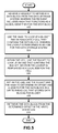
- FIG. 7 presents a flow chart illustrating how a failure of a storage device is handled in accordance with the disclosed embodiments.
- the system detects a failure associated with a bucket in a cell (step 702 ).
- the system marks the bucket as non-writable (step 704 ).
- the system then performs a fast block-copy of the bucket to a new OSD in the cell (step 706 ).
- the systems also updates the BDB for the cell to indicate that the bucket is associated with the new OSD (step 708 ).
- the system increments the new generation number for the OSD (step 710 ). Recall that when a degraded OSD is restarted after a failure, it will not accept any reads because its generation number is old.
- the described embodiments relate to a data storage system for immutable data that improves performance by minimizing the number of disk seeks required to perform put( ) and get( ) operations. It also minimizes the number of individual data items that have to be modified when recovering from a disk failure. This is accomplished by aggregating thousands of data blocks into each bucket, and then using an access architecture that maps these larger buckets to specific storage locations, instead of mapping individual data blocks to specific storage locations. Because this multi-level lookup architecture first maps hashes to buckets using HDB 330 , and then maps buckets to OSDs using BDB 342 , when the system moves a copy of a bucket (for example, during a failure-recovery operation), the associated entry in HDB 330 for the bucket does not change. Only the entry in BDB 342 changes and this change is very fast because BDB 342 is relatively small and can fit in memory.
Abstract
Description
Claims (21)
Priority Applications (1)
| Application Number | Priority Date | Filing Date | Title |
|---|---|---|---|
| US14/091,119 US9405643B2 (en) | 2013-11-26 | 2013-11-26 | Multi-level lookup architecture to facilitate failure recovery |
Applications Claiming Priority (1)
| Application Number | Priority Date | Filing Date | Title |
|---|---|---|---|
| US14/091,119 US9405643B2 (en) | 2013-11-26 | 2013-11-26 | Multi-level lookup architecture to facilitate failure recovery |
Publications (2)
| Publication Number | Publication Date |
|---|---|
| US20150149500A1 US20150149500A1 (en) | 2015-05-28 |
| US9405643B2 true US9405643B2 (en) | 2016-08-02 |
Family
ID=53183564
Family Applications (1)
| Application Number | Title | Priority Date | Filing Date |
|---|---|---|---|
| US14/091,119 Active 2034-07-16 US9405643B2 (en) | 2013-11-26 | 2013-11-26 | Multi-level lookup architecture to facilitate failure recovery |
Country Status (1)
| Country | Link |
|---|---|
| US (1) | US9405643B2 (en) |
Cited By (2)
| Publication number | Priority date | Publication date | Assignee | Title |
|---|---|---|---|---|
| US9935831B1 (en) * | 2014-06-03 | 2018-04-03 | Big Switch Networks, Inc. | Systems and methods for controlling network switches using a switch modeling interface at a controller |
| CN109992452A (en) * | 2019-03-29 | 2019-07-09 | 新华三技术有限公司 | A kind of fault handling method and device |
Families Citing this family (9)
| Publication number | Priority date | Publication date | Assignee | Title |
|---|---|---|---|---|
| US10140309B2 (en) * | 2014-06-10 | 2018-11-27 | Alfresco Software, Inc. | File tracking on client machines synchronized with a content management system repository |
| EP3091451A1 (en) * | 2015-04-28 | 2016-11-09 | Micro Systemation AB | Database rollback using wal |
| CN105117402B (en) * | 2015-07-16 | 2018-08-28 | 中国人民大学 | Daily record data sharding method and device |
| CN107391634B (en) * | 2017-06-30 | 2021-04-09 | 北京奇虎科技有限公司 | Data migration method and device |
| CN107608821B (en) * | 2017-09-29 | 2021-04-30 | 郑州云海信息技术有限公司 | Data reading method, device and equipment based on erasure codes |
| CN111104239A (en) * | 2019-11-21 | 2020-05-05 | 北京浪潮数据技术有限公司 | Hard disk fault processing method, system and device for distributed storage cluster |
| CN111858529B (en) * | 2020-06-29 | 2024-04-09 | 广东浪潮大数据研究有限公司 | Log playback method, device, equipment and computer readable storage medium |
| CN112711497A (en) * | 2021-01-05 | 2021-04-27 | 浪潮云信息技术股份公司 | Recovery method and system for unfolded faults of container deployment Ceph cluster object |
| CN113064859B (en) * | 2021-03-26 | 2022-11-04 | 山东英信计算机技术有限公司 | Metadata processing method and device, electronic equipment and storage medium |
Citations (18)
| Publication number | Priority date | Publication date | Assignee | Title |
|---|---|---|---|---|
| US6374262B1 (en) | 1998-03-25 | 2002-04-16 | Fujitsu Limited | Relational database synchronization method and a recording medium storing a program therefore |
| US20030115433A1 (en) | 2001-12-14 | 2003-06-19 | Hitachi Ltd. | Remote storage system and method |
| US20040062106A1 (en) * | 2002-09-27 | 2004-04-01 | Bhashyam Ramesh | System and method for retrieving information from a database |
| US20050125627A1 (en) | 2003-12-09 | 2005-06-09 | Michael Kilian | Methods and apparatus for caching a location index in a data storage system |
| US20050125625A1 (en) | 2003-12-09 | 2005-06-09 | Michael Kilian | Methods and apparatus for parsing a content address to facilitate selection of a physical storage location in a data storage system |
| US20050144172A1 (en) | 2003-12-09 | 2005-06-30 | Michael Kilian | Methods and apparatus for generating a content address to indicate data units written to a storage system proximate in time |
| US20060095458A1 (en) * | 2004-10-29 | 2006-05-04 | Microsoft Corporation | Multi-level nested open hashed data stores |
| US20060116989A1 (en) * | 2004-11-30 | 2006-06-01 | Srikanth Bellamkonda | Efficient data aggregation operations using hash tables |
| US20080059749A1 (en) | 2006-09-06 | 2008-03-06 | Microsoft Corporation | Dynamic Fragment Mapping |
| US7443321B1 (en) * | 2007-02-13 | 2008-10-28 | Packeteer, Inc. | Compression of stream data using a hierarchically-indexed database |
| US7788224B2 (en) | 2003-10-08 | 2010-08-31 | Alcatel | Fast database replication |
| US8392482B1 (en) | 2008-03-31 | 2013-03-05 | Amazon Technologies, Inc. | Versioning of database partition maps |
| US20130110845A1 (en) * | 2007-12-12 | 2013-05-02 | Oracle International Corporation | Bulk matching with update |
| US20130254240A1 (en) | 2012-03-22 | 2013-09-26 | Takahiro Kurita | Method of processing database, database processing apparatus, computer program product |
| US20140095458A1 (en) * | 2012-09-28 | 2014-04-03 | Samsung Electronics Co., Ltd. | Storage device for storing directory entries, directory entry lookup apparatus and method, and storage medium storing directory entry lookup program |
| US20140195745A1 (en) | 2013-01-04 | 2014-07-10 | International Business Machines Corporation | Data Storage Mechanism Using Storage System Determined Write Locations |
| US8959067B1 (en) | 2012-08-08 | 2015-02-17 | Amazon Technologies, Inc. | Data storage inventory indexing |
| US20150213016A1 (en) * | 2012-10-17 | 2015-07-30 | Realtimetech Co., Ltd. | Method for performing full-text-based logic operation using hash |
-
2013
- 2013-11-26 US US14/091,119 patent/US9405643B2/en active Active
Patent Citations (18)
| Publication number | Priority date | Publication date | Assignee | Title |
|---|---|---|---|---|
| US6374262B1 (en) | 1998-03-25 | 2002-04-16 | Fujitsu Limited | Relational database synchronization method and a recording medium storing a program therefore |
| US20030115433A1 (en) | 2001-12-14 | 2003-06-19 | Hitachi Ltd. | Remote storage system and method |
| US20040062106A1 (en) * | 2002-09-27 | 2004-04-01 | Bhashyam Ramesh | System and method for retrieving information from a database |
| US7788224B2 (en) | 2003-10-08 | 2010-08-31 | Alcatel | Fast database replication |
| US20050125627A1 (en) | 2003-12-09 | 2005-06-09 | Michael Kilian | Methods and apparatus for caching a location index in a data storage system |
| US20050125625A1 (en) | 2003-12-09 | 2005-06-09 | Michael Kilian | Methods and apparatus for parsing a content address to facilitate selection of a physical storage location in a data storage system |
| US20050144172A1 (en) | 2003-12-09 | 2005-06-30 | Michael Kilian | Methods and apparatus for generating a content address to indicate data units written to a storage system proximate in time |
| US20060095458A1 (en) * | 2004-10-29 | 2006-05-04 | Microsoft Corporation | Multi-level nested open hashed data stores |
| US20060116989A1 (en) * | 2004-11-30 | 2006-06-01 | Srikanth Bellamkonda | Efficient data aggregation operations using hash tables |
| US20080059749A1 (en) | 2006-09-06 | 2008-03-06 | Microsoft Corporation | Dynamic Fragment Mapping |
| US7443321B1 (en) * | 2007-02-13 | 2008-10-28 | Packeteer, Inc. | Compression of stream data using a hierarchically-indexed database |
| US20130110845A1 (en) * | 2007-12-12 | 2013-05-02 | Oracle International Corporation | Bulk matching with update |
| US8392482B1 (en) | 2008-03-31 | 2013-03-05 | Amazon Technologies, Inc. | Versioning of database partition maps |
| US20130254240A1 (en) | 2012-03-22 | 2013-09-26 | Takahiro Kurita | Method of processing database, database processing apparatus, computer program product |
| US8959067B1 (en) | 2012-08-08 | 2015-02-17 | Amazon Technologies, Inc. | Data storage inventory indexing |
| US20140095458A1 (en) * | 2012-09-28 | 2014-04-03 | Samsung Electronics Co., Ltd. | Storage device for storing directory entries, directory entry lookup apparatus and method, and storage medium storing directory entry lookup program |
| US20150213016A1 (en) * | 2012-10-17 | 2015-07-30 | Realtimetech Co., Ltd. | Method for performing full-text-based logic operation using hash |
| US20140195745A1 (en) | 2013-01-04 | 2014-07-10 | International Business Machines Corporation | Data Storage Mechanism Using Storage System Determined Write Locations |
Non-Patent Citations (1)
| Title |
|---|
| U.S. Appl. No. 14/224,786, filed Mar. 25, 2014, Office Action, Mailing Date Apr. 6, 2016. |
Cited By (3)
| Publication number | Priority date | Publication date | Assignee | Title |
|---|---|---|---|---|
| US9935831B1 (en) * | 2014-06-03 | 2018-04-03 | Big Switch Networks, Inc. | Systems and methods for controlling network switches using a switch modeling interface at a controller |
| CN109992452A (en) * | 2019-03-29 | 2019-07-09 | 新华三技术有限公司 | A kind of fault handling method and device |
| CN109992452B (en) * | 2019-03-29 | 2021-06-18 | 新华三技术有限公司 | Fault processing method and device |
Also Published As
| Publication number | Publication date |
|---|---|
| US20150149500A1 (en) | 2015-05-28 |
Similar Documents
| Publication | Publication Date | Title |
|---|---|---|
| US10248356B2 (en) | Using scratch extents to facilitate copying operations in an append-only storage system | |
| US10452271B2 (en) | Reconstructing in-memory indices in a distributed data storage system | |
| US9405643B2 (en) | Multi-level lookup architecture to facilitate failure recovery | |
| US9547706B2 (en) | Using colocation hints to facilitate accessing a distributed data storage system | |
| US10296518B2 (en) | Managing distributed deletes in a replicated storage system | |
| US9772783B2 (en) | Constructing an index to facilitate accessing a closed extent in an append-only storage system | |
| US8930648B1 (en) | Distributed deduplication using global chunk data structure and epochs | |
| US10310904B2 (en) | Distributed technique for allocating long-lived jobs among worker processes | |
| US9720607B2 (en) | Append-only storage system supporting open and closed extents | |
| US10659225B2 (en) | Encrypting existing live unencrypted data using age-based garbage collection | |
| US8914379B2 (en) | Index constructing method, search method, device and system | |
| US8825602B1 (en) | Systems and methods for providing data protection in object-based storage environments | |
| US9619322B2 (en) | Erasure-coding extents in an append-only storage system | |
| US10437682B1 (en) | Efficient resource utilization for cross-site deduplication | |
| CN103501319A (en) | Low-delay distributed storage system for small files | |
| US20210263919A1 (en) | Centralized Storage for Search Servers | |
| US9767139B1 (en) | End-to-end data integrity in parallel storage systems | |
| US11055005B2 (en) | Background deduplication using trusted fingerprints | |
| CN107798063A (en) | Snap processing method and snapshot processing unit | |
| US10387384B1 (en) | Method and system for semantic metadata compression in a two-tier storage system using copy-on-write | |
| US10997040B1 (en) | System and method for weight based data protection | |
| US11176034B2 (en) | System and method for inline tiering of write data | |
| US20210286720A1 (en) | Managing snapshots and clones in a scale out storage system | |
| US9967310B2 (en) | Using an RPC framework to facilitate out-of-band data transfers | |
| US10922012B1 (en) | Fair data scrubbing in a data storage system |
Legal Events
| Date | Code | Title | Description |
|---|---|---|---|
| AS | Assignment |
Owner name: DROPBOX, INC., CALIFORNIA Free format text: ASSIGNMENT OF ASSIGNORS INTEREST;ASSIGNORS:COWLING, JAMES;MODZELEWSKI, KEVIN P.;REEL/FRAME:031842/0273 Effective date: 20131126 |
|
| AS | Assignment |
Owner name: JPMORGAN CHASE BANK, N.A., AS COLLATERAL AGENT, NEW YORK Free format text: SECURITY INTEREST;ASSIGNOR:DROPBOX, INC.;REEL/FRAME:032510/0890 Effective date: 20140320 Owner name: JPMORGAN CHASE BANK, N.A., AS COLLATERAL AGENT, NE Free format text: SECURITY INTEREST;ASSIGNOR:DROPBOX, INC.;REEL/FRAME:032510/0890 Effective date: 20140320 |
|
| STCF | Information on status: patent grant |
Free format text: PATENTED CASE |
|
| AS | Assignment |
Owner name: JPMORGAN CHASE BANK, N.A., AS COLLATERAL AGENT, NE Free format text: SECURITY INTEREST;ASSIGNOR:DROPBOX, INC.;REEL/FRAME:042254/0001 Effective date: 20170403 Owner name: JPMORGAN CHASE BANK, N.A., AS COLLATERAL AGENT, NEW YORK Free format text: SECURITY INTEREST;ASSIGNOR:DROPBOX, INC.;REEL/FRAME:042254/0001 Effective date: 20170403 |
|
| MAFP | Maintenance fee payment |
Free format text: PAYMENT OF MAINTENANCE FEE, 4TH YEAR, LARGE ENTITY (ORIGINAL EVENT CODE: M1551); ENTITY STATUS OF PATENT OWNER: LARGE ENTITY Year of fee payment: 4 |
|
| AS | Assignment |
Owner name: JPMORGAN CHASE BANK, N.A., AS COLLATERAL AGENT, NEW YORK Free format text: PATENT SECURITY AGREEMENT;ASSIGNOR:DROPBOX, INC.;REEL/FRAME:055670/0219 Effective date: 20210305 |
|
| MAFP | Maintenance fee payment |
Free format text: PAYMENT OF MAINTENANCE FEE, 8TH YEAR, LARGE ENTITY (ORIGINAL EVENT CODE: M1552); ENTITY STATUS OF PATENT OWNER: LARGE ENTITY Year of fee payment: 8 |