US9407348B2 - Communication overhead reduction apparatus, systems, and methods - Google Patents
Communication overhead reduction apparatus, systems, and methods Download PDFInfo
- Publication number
- US9407348B2 US9407348B2 US14/602,416 US201514602416A US9407348B2 US 9407348 B2 US9407348 B2 US 9407348B2 US 201514602416 A US201514602416 A US 201514602416A US 9407348 B2 US9407348 B2 US 9407348B2
- Authority
- US
- United States
- Prior art keywords
- sta
- chains
- training symbols
- response
- communication
- Prior art date
- Legal status (The legal status is an assumption and is not a legal conclusion. Google has not performed a legal analysis and makes no representation as to the accuracy of the status listed.)
- Expired - Lifetime
Links
- 238000004891 communication Methods 0.000 title claims abstract description 98
- 238000000034 method Methods 0.000 title claims abstract description 50
- 238000012549 training Methods 0.000 claims abstract description 109
- 230000004044 response Effects 0.000 claims abstract description 56
- 230000005540 biological transmission Effects 0.000 claims description 13
- 238000012545 processing Methods 0.000 claims description 5
- 230000008569 process Effects 0.000 claims description 3
- 238000010586 diagram Methods 0.000 description 12
- 230000000694 effects Effects 0.000 description 10
- 239000011159 matrix material Substances 0.000 description 10
- 238000005259 measurement Methods 0.000 description 6
- 230000007246 mechanism Effects 0.000 description 3
- 230000003044 adaptive effect Effects 0.000 description 2
- 230000008901 benefit Effects 0.000 description 2
- 238000000354 decomposition reaction Methods 0.000 description 2
- 230000002452 interceptive effect Effects 0.000 description 2
- 230000003287 optical effect Effects 0.000 description 2
- 230000006978 adaptation Effects 0.000 description 1
- 230000002730 additional effect Effects 0.000 description 1
- 230000001413 cellular effect Effects 0.000 description 1
- 238000004590 computer program Methods 0.000 description 1
- 239000004020 conductor Substances 0.000 description 1
- 230000006870 function Effects 0.000 description 1
- 230000000737 periodic effect Effects 0.000 description 1
- 238000001228 spectrum Methods 0.000 description 1
- 238000006467 substitution reaction Methods 0.000 description 1
Images


Classifications
-
- H—ELECTRICITY
- H04—ELECTRIC COMMUNICATION TECHNIQUE
- H04B—TRANSMISSION
- H04B7/00—Radio transmission systems, i.e. using radiation field
- H04B7/02—Diversity systems; Multi-antenna system, i.e. transmission or reception using multiple antennas
- H04B7/04—Diversity systems; Multi-antenna system, i.e. transmission or reception using multiple antennas using two or more spaced independent antennas
- H04B7/06—Diversity systems; Multi-antenna system, i.e. transmission or reception using multiple antennas using two or more spaced independent antennas at the transmitting station
- H04B7/0613—Diversity systems; Multi-antenna system, i.e. transmission or reception using multiple antennas using two or more spaced independent antennas at the transmitting station using simultaneous transmission
- H04B7/0684—Diversity systems; Multi-antenna system, i.e. transmission or reception using multiple antennas using two or more spaced independent antennas at the transmitting station using simultaneous transmission using different training sequences per antenna
-
- H—ELECTRICITY
- H04—ELECTRIC COMMUNICATION TECHNIQUE
- H04B—TRANSMISSION
- H04B7/00—Radio transmission systems, i.e. using radiation field
- H04B7/02—Diversity systems; Multi-antenna system, i.e. transmission or reception using multiple antennas
- H04B7/04—Diversity systems; Multi-antenna system, i.e. transmission or reception using multiple antennas using two or more spaced independent antennas
- H04B7/0413—MIMO systems
- H04B7/0417—Feedback systems
-
- H—ELECTRICITY
- H04—ELECTRIC COMMUNICATION TECHNIQUE
- H04B—TRANSMISSION
- H04B7/00—Radio transmission systems, i.e. using radiation field
- H04B7/02—Diversity systems; Multi-antenna system, i.e. transmission or reception using multiple antennas
- H04B7/04—Diversity systems; Multi-antenna system, i.e. transmission or reception using multiple antennas using two or more spaced independent antennas
- H04B7/06—Diversity systems; Multi-antenna system, i.e. transmission or reception using multiple antennas using two or more spaced independent antennas at the transmitting station
- H04B7/0697—Diversity systems; Multi-antenna system, i.e. transmission or reception using multiple antennas using two or more spaced independent antennas at the transmitting station using spatial multiplexing
-
- H—ELECTRICITY
- H04—ELECTRIC COMMUNICATION TECHNIQUE
- H04W—WIRELESS COMMUNICATION NETWORKS
- H04W52/00—Power management, e.g. TPC [Transmission Power Control], power saving or power classes
- H04W52/04—TPC
- H04W52/38—TPC being performed in particular situations
- H04W52/42—TPC being performed in particular situations in systems with time, space, frequency or polarisation diversity
-
- H—ELECTRICITY
- H04—ELECTRIC COMMUNICATION TECHNIQUE
- H04W—WIRELESS COMMUNICATION NETWORKS
- H04W56/00—Synchronisation arrangements
- H04W56/001—Synchronization between nodes
-
- H—ELECTRICITY
- H04—ELECTRIC COMMUNICATION TECHNIQUE
- H04L—TRANSMISSION OF DIGITAL INFORMATION, e.g. TELEGRAPHIC COMMUNICATION
- H04L5/00—Arrangements affording multiple use of the transmission path
- H04L5/003—Arrangements for allocating sub-channels of the transmission path
- H04L5/0044—Arrangements for allocating sub-channels of the transmission path allocation of payload
- H04L5/0046—Determination of how many bits are transmitted on different sub-channels
-
- H—ELECTRICITY
- H04—ELECTRIC COMMUNICATION TECHNIQUE
- H04W—WIRELESS COMMUNICATION NETWORKS
- H04W84/00—Network topologies
- H04W84/02—Hierarchically pre-organised networks, e.g. paging networks, cellular networks, WLAN [Wireless Local Area Network] or WLL [Wireless Local Loop]
- H04W84/10—Small scale networks; Flat hierarchical networks
- H04W84/12—WLAN [Wireless Local Area Networks]
-
- H—ELECTRICITY
- H04—ELECTRIC COMMUNICATION TECHNIQUE
- H04W—WIRELESS COMMUNICATION NETWORKS
- H04W84/00—Network topologies
- H04W84/18—Self-organising networks, e.g. ad-hoc networks or sensor networks
Definitions
- Various embodiments described herein relate to communications generally, including apparatus, systems, and methods used to transmit and receive information, such as space-time communications systems.
- Spatial multiplexing communications system performance including SDMA (space division, multiple access) and MIMO (multiple-input, multiple-output) systems, may be improved by the activities of training and calibration.
- Training may include transmitting known signals to a receiver to increase the reliability of estimating channel state information. While longer training sequences may provide increased reception accuracy, the use of such sequences may also reduce the advantage to be gained by using spatial multiplexing in the first place (i.e., high data rates). Similarly, while calibrating transmitter power and receiver gains can contribute to improved data transmission rates, the additional time required for periodic calibration may decrease the ultimate system capability to communicate large amounts of data in a short time span.
- FIG. 1 is a block diagram of apparatus and a system operating according to various embodiments
- FIG. 2 is a block diagram of apparatus and a system operating according to various embodiments
- FIG. 3 is a block diagram of apparatus and a system operating according to various embodiments
- FIGS. 4A, 4B and 4C are block diagrams of exemplary packet formats that can be utilized by the apparatus and system of FIG. 3 ;
- FIGS. 5A and 5B are a block diagram of an apparatus operating according to various embodiments, as well as an exemplary packet format which may be implemented thereby, respectively;
- FIG. 6 is a flow chart illustrating several training and calibration methods according to various embodiments.
- FIG. 7 is a flow chart illustrating several alternative training and calibration methods according to various embodiments.
- FIG. 8 is a block diagram of an article according to various embodiments.
- MIMO system techniques can multiply the data rate of a wireless local area network (WLAN) by nearly as many times as the number of antennas employed by an access point (AP) without the need for increased spectrum usage.
- MIMO systems exploiting channel state information (CSI) at the transmitter have the potential to reduce receiver complexity while achieving increased channel capacity.
- Common examples of such techniques include transmit beamforming (e.g., singular value decomposition or SVD), adaptive bit loading (ABL), and power allocation (e.g., tone puncturing).
- transmit beamforming e.g., singular value decomposition or SVD
- ABL adaptive bit loading
- power allocation e.g., tone puncturing
- relevant CSI cannot be obtained directly via training, because training symbol measurements are the aggregate response of several components, including the transmit chain response of the transmitting device, the wireless channel response, and the receive chain response of the receiving device. Therefore, accurate measurements of training symbols may be assisted by calibration.
- CSI at the transmitter may be obtained by having the transmitter send training symbols to a receiver, and then feeding back receiver measurements of the received channel response to the transmitter.
- this time-consuming feedback process does not lend itself to situations where high throughput is desired, such as when various forms of the Institute of Electrical and Electronics Engineers (IEEE) 802.11 protocols are employed, including those considered by the High Throughput (HT) Study Group.
- IEEE Institute of Electrical and Electronics Engineers
- the round-trip channel responses of 2-by-2 and 4-by-4 MIMO systems using such feedback typically require 62 ⁇ s and 247 ⁇ s, respectively, at a 54 Mbps channel data rate.
- IEEE 802.11 standards for Information Technology—Telecommunications and Information Exchange between Systems—Local and Metropolitan Area Network—Specific Requirements—Part 11: Wireless LAN Medium Access Control (MAC) and Physical Layer (PHY), ISO/IEC 8802-11: 1999” and related amendments.
- MAC Medium Access Control
- PHY Physical Layer
- calibration schemes attempt to provide a ratio of transmit chain gain to corresponding receive chain gain that is substantially constant for each antenna, at both the transmitter and the receiver.
- calibration on one side i.e., a transmitter or receiver
- channel estimation on the other side i.e., the corresponding receiver or transmitter
- Backward-compatible protocols using existing RTS/CTS request-to-send/clear-to-send symbols or messages may be used (e.g., IEEE 802.11 and related amendments).
- calibration and training including channel estimation, at both the transmitter and receiver may be accomplished during an exchange of RTS/CTS symbols without explicit CSI feedback.
- a “symbol” or “training symbol” may include any character, symbol, or message known to a receiver, including, for example, preambles, such as the long and short preambles defined with respect to an IEEE 802.11a standard packet.
- FIG. 1 is a block diagram of apparatus 100 and a system 102 operating according to various embodiments.
- a first device 104 such as an access point (AP) or station (STA) may communicate with a second device 108 , such as a STA or AP.
- the first device 104 may have a plurality of antennas 112 (e.g., three antennas 112 ), with one or more transmit chains 114 and one or more receive chains 116 coupled to each antenna 112 .
- Each transmit chain 114 -receive chain 116 pair may be included in a communication chain 118 .
- the second device 108 may also have a plurality of antennas 120 (e.g., two antennas 120 ), where each antenna 120 also may be coupled to one or more transmit chains 124 and/or one or more receive chains 126 .
- Each transmit chain 124 -receive chain 126 pair may be included in a communication chain 128 .
- Each transmit chain 114 , 124 in one device 104 , 108 , respectively, may send training and calibration symbols to all receive chains 126 , 116 included in another device 108 , 104 , respectively.
- transceiver e.g., a device including a transmitter and a receiver
- a transceiver may be included in a transmit chain and/or a receive chain.
- Some communication systems may employ CSI, which may be acquired by receiving symbols, including preambles.
- the measurements of received preambles may include more than just the response of the wireless channel.
- such measurements may include the combined responses of the transmit chains sending the preambles, the wireless channel, and the receive chain receiving the preambles.
- the beamforming matrix can be affected by the combined responses of the transmit chains of the AP, the wireless channel, and the receive chains of the STA.
- the chain responses of the STA may not be available to the AP.
- the device 104 can estimate the aggregate channel matrix from the input of the device 108 transmit chains 124 to the output of the device 104 receive chains 116 for the n-th subcarrier as shown in Equation (1):
- H u [ ⁇ A ⁇ ⁇ 1 0 0 0 ⁇ A ⁇ ⁇ 2 0 0 0 ⁇ A ⁇ ⁇ 3 ] ⁇ [ h 11 h 12 h 21 h 22 h 31 h 32 ] ⁇ [ a S ⁇ ⁇ 1 0 0 a S ⁇ ⁇ 2 ] ( 1 )
- H is the wireless channel matrix for the uplink
- ⁇ A1 , ⁇ A2 and ⁇ A3 are the responses of the device 104 receive chains 116
- ⁇ S1 and ⁇ S2 are the responses of the transmit chains for the device 108 .
- the subcarrier index, n has been omitted for simplicity.
- H may not be observed by the device 104 , although it may be contained within H u , where H u is the measurement of the received training symbols (e.g., preambles). However, even when H is not available directly, in some embodiments, the matrix H u may be used without further processing.
- transmit beamforming including techniques such as SVD and SDMA
- feedback overhead can reduce physical layer efficiency by more than 40%.
- reducing or removing feedback can significantly improve physical layer efficiency.
- several backward compatible protocols will be described, employing the exchange of existing RTS/CTS symbols, as well as various calibration techniques, some of which operate to adjust transmit/receive chain power and gain levels so that the ratio of a transmit gain to the corresponding receive gain comprises two constants (one for each device 104 antenna 112 , and the other for each device 108 antenna 120 ).
- Equation (2) the signals received at the device 108 from the device 104 in the downlink of FIG. 1 may be illustrated by Equation (2) below:
- [ y S ⁇ ⁇ 1 y S ⁇ ⁇ 2 ] [ ⁇ S ⁇ ⁇ 1 0 0 ⁇ S ⁇ ⁇ 2 0 ] ⁇ [ h 11 h 21 h 31 h 12 h 22 h 32 ] ⁇ [ ⁇ A ⁇ ⁇ 1 0 0 0 ⁇ A ⁇ ⁇ 2 0 0 0 ⁇ A ⁇ ⁇ 3 ] ⁇ H d ⁇ [ x A ⁇ ⁇ 1 x A 2 x A ⁇ ⁇ 3 ] ( 2 )
- y S1 and y S2 signify the received signal at the output of the device 108 receive chains 126 ;
- x A1 , x A2 , and x A3 are the symbols sent to the device 108 ;
- ⁇ A1 , ⁇ A2 and ⁇ A3 are the device 104 transmit chain 114 gains; and
- ⁇ S1 and ⁇ S2 are the device 108 receive chain 126 gains.
- [ y A ⁇ ⁇ 1 y A ⁇ ⁇ 2 y A ⁇ ⁇ 3 ] [ ⁇ A ⁇ ⁇ 1 0 0 0 ⁇ A ⁇ ⁇ 2 0 0 ⁇ A ⁇ ⁇ 3 ] ⁇ [ h 11 h 12 h 21 h 22 h 31 h 32 ] ⁇ [ ⁇ S ⁇ ⁇ 1 0 0 ⁇ S ⁇ ⁇ 2 ] ⁇ H u ⁇ [ x S ⁇ ⁇ 1 x S ⁇ ⁇ 2 ] ( 3 )
- x S1 and x S2 are the symbols sent to the device 104
- y A1 , y A2 , and y A3 are the signals received at the output of the device 104 receive chains 116
- ⁇ S1 and ⁇ S2 are the device 108 transmit chain 124 gains
- ⁇ A1 , ⁇ A2 and ⁇ A3 are the device 104 receive chain 116 gains.
- Equation (4) A sufficient condition for reciprocity may be shown in Equations (4) and (5) as follows:
- H d k n H u T , where H d and H u T differ by the product of a scalar k n .
- calibration and compensation may be effected at device 104 and device 108 . Two exemplary schemes that may be used to achieve these conditions are described next.
- FIG. 2 is a block diagram of apparatus 200 and a system 202 operating according to various embodiments.
- Each device 204 , 208 (which may be similar to or identical to devices 104 , 108 , respectively, as shown in FIG. 1 , and may include an AP and/or a STA) may have multiple transmit power control (TPC) levels and multiple receive gain control levels, including automatic gain control (AGC) levels, for each of the included communication chains.
- TPC transmit power control
- AGC automatic gain control
- transmit and receive responses, ⁇ and ⁇ may vary with selected TPC and AGC settings.
- implementing a series of training exchanges for each possible combination of TPC and AGC may be time-consuming if there are a large number of combinations.
- desired combinations of TPC and AGC settings may be established relatively quickly with respect to the devices 204 , 208 , such that calibration can occur rapidly.
- one device 204 may send one or more symbols 230 , such as a request to transmit (e.g., a legacy RTS symbol or message) to the device 208 using a default TPC. Then, after the device 208 receives the transmitted symbol(s) (e.g., the RTS) 230 , the device 208 may determine a set of desired AGC and TPC settings for the link to the device 204 .
- symbols 230 such as a request to transmit (e.g., a legacy RTS symbol or message) to the device 208 using a default TPC.
- the device 208 may send a symbol 234 in response, such as a clear to transmit response (e.g., a legacy CTS symbol or message) and N r training symbols 238 , where N r is the number of receive antennas (or RF chains) employed by the device 208 , which may use the same N r antennas to receive one or more MIMO modulated data packets.
- the N r symbols 238 which may be used for training, can be sent in turn by each one of the N r antennas, perhaps using one symbol per antenna.
- the device 204 may determine a set of desired AGC and TPC settings for the link to the device 208 .
- Reception of the N r training symbols 238 may be used by the device 204 to estimate the N t ⁇ N r channel, which may be a MIMO channel, where N t is the number of transmit antennas (or RF chains) included in the device 204 .
- the device 204 may use the same N t antennas for channel estimation and data transmission, including MIMO data transmission.
- the N r training symbols 238 received by the device 208 may also be used to calibrate the communication chains (e.g., chains 128 shown in FIG. 1 ) included in the device 208 for the newly determined set of TPC and AGC settings.
- the device 204 may subsequently transmit N t training symbols 240 and data 244 , including MIMO modulated data, to the device 208 .
- the N t training symbols 240 may be sent by N t antennas (or RF chains), perhaps using one symbol per antenna at a desired TPC setting.
- the device 204 may receive the N t training symbols 240 at a desired AGC setting and calibrate the communication chains included in the device 204 (e.g., chains 118 in FIG. 1 ).
- the communication chains included in the device 208 may likewise be calibrated after transmission of the N t training symbols 240 .
- Beamforming, perhaps as a form of MIMO system modulation may be performed by the device 204 with respect to data sent by the device 204 to the device 208 using the channel information obtained as a result of receiving the response 234 from the device 208 .
- the device 208 may set a desired AGC level and perform channel estimation. The resulting channel estimates may permit the device 208 to demodulate beamformed data provided by the device 204 .
- an acknowledgment 248 e.g., a legacy ACK response
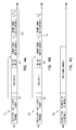
- FIG. 3 is a block diagram of apparatus 300 and a system 302 operating according to various embodiments.
- Each device 304 , 308 may be similar to or identical to devices 104 , 108 , respectively, shown in FIG. 1 , and may include an AP and/or a STA.
- FIG. 4 is a block diagram of exemplary packet formats that can be utilized by the apparatus and system of FIG. 3 .
- the N t and N r training symbols may be attached directly to the request to transmit (e.g., legacy RTS) symbol and the clear to transmit response (e.g., legacy CTS) symbol, respectively, where N t and N r are the number of antennas at the devices (or the number of communication chains), as described previously.
- the training symbols may be used to both calibrate the transmitter and enable the channel estimation of the receiver in one or more of the communication chains included in the apparatus 300 .
- a device prepared to send data may transmit a symbol 330 , 430 or packet, such as a legacy RTS packet, to another device, such as device 308 .
- N t training symbols 340 may be attached to the end of the packet 330 , where N t can be the number of transmit chains included in the device 304 .
- the length field 448 in the packet 330 , 430 may be set to protect up to the end of the pad bits 450 , as specified in the IEEE 802.11 standard for legacy RTS packets.
- a legacy device may receive the RTS packet 330 , 430 correctly and perform collision avoidance operations as needed.
- the N t symbols 340 may be sent in turn by the N t communication chains included in the device 304 .
- a calibration algorithm may be performed as the N t symbols 340 are sent to calibrate both the transmit and the receive chains of the device 304 .
- the device 308 receiving the N t symbols 340 , 440 and the symbol 330 , 430 may estimate the associated channels and compute demultiplexing matrices to enhance data reception, as is known to those of ordinary skill in the art.
- a training symbol x 0 for the n-th sub-carrier may be sent using a first transmit chain (e.g., transmit chain #1), and the output of a second receive chain (e.g., receive chain #2) may be measured.
- a training symbol x 0 for the n-th sub-carrier may be sent using a second transmit chain (e.g., transmit chain #2), and the output of a first receive chain (e.g., receive chain #1) may be measured.
- Each execution of the loop may involve sending a training symbol x 0 for the n-th sub-carrier using the first transmit chain and measuring the output of receive chain i.
- loop execution may involve sending a training symbol x 0 for the n-th sub-carrier using transmit chain i, and measuring the output of the first receive chain.
- Equation (8) may be simplified as follows:
- the device 308 receiving the symbol 330 may respond by sending another symbol (or symbols, and/or packets, such as a legacy CTS symbol). This transmission may occur if the status of a network allocation vector (NAV) indicates the channel is idle.
- N r training symbols 338 , 438 may be attached to the end of the symbol or packet 334 , 434 , where N r is the number of the receive chains included in the device 308 .
- the N r symbols 338 , 438 may be sent in turn by N r antennas coupled to the receive chains included in the device 308 to receive data packets 344 , 444 .
- the length field 454 in the packet 334 , 434 may be set to protect up to the end of the pad bits 458 , as specified in the IEEE 802.11 standard for legacy CTS packets.
- a legacy device may receive the CTS packet 334 , 434 correctly and perform collision avoidance operations as needed.
- a calibration algorithm may be performed as the N r symbols 338 , 438 are sent, in order to calibrate the transmit and the receive chains included in the device 308 .
- the device 304 receiving the N r symbols 338 , 438 and the response symbol 334 , 434 (e.g., a legacy CTS packet) may estimate the associated channels and determine beamforming matrices for transmission of the data 344 , 444 .
- the device 304 may then send the data 344 , 444 using transmit beamforming, adaptive bit loading, and/or power allocation techniques, as is known to those of skill in the art.
- a symbol of acknowledgment (e.g., a legacy ACK symbol or packet) 348 may be received by the device 304 after the data 344 , 444 is sent.
- the device 308 receiving the request to send 330 , 430 symbol or packet may estimate the channel matrix (e.g., for each orthogonal frequency division multiplexing (OFDM) tone) and form a corresponding demultiplexing matrix (e.g., the “U” matrix in SVD techniques) by exploiting the attached training symbols 340 , 440 .
- the channel matrix e.g., for each orthogonal frequency division multiplexing (OFDM) tone
- a corresponding demultiplexing matrix e.g., the “U” matrix in SVD techniques
- the device 304 receiving the clear to send response 334 , 434 symbol or packet may also estimate the associated channel and compute a beamforming matrix (e.g., the “V” matrix in SVD techniques) by exploiting the attached training symbols 338 , 438 .
- a beamforming matrix e.g., the “V” matrix in SVD techniques
- an apparatus 100 , 200 , 300 may be similar to or identical to the devices 104 , 108 , 204 , 208 , and 304 , 308 , including devices such as an AP and/or STA.
- Such apparatus 100 , 200 , 300 may therefore include a device 104 , 204 , 304 having a first number of communication chains 118 to transmit to a second apparatus 100 , 200 , 300 or device 108 , 208 , 308 a first number of training symbols corresponding to the first number of communication chains 118 and to solicit a response from the second apparatus 100 , 200 , 300 or device 108 , 208 , 308 including a second number of training symbols corresponding to a number of communication chains 128 included in the second device 108 , 208 , 308 .
- the first number of communication chains 118 may correspond to a number of transmit chains 114
- the second number of communication chains 128 may correspond to a number of receive chains 126
- the first number of communication chains 118 may correspond to a number of receive chains 116
- the second number of communication chains 128 may correspond to a number of transmit chains 124
- the apparatus 100 , 200 , 300 may include a calibration module 160 to calibrate the transmit chains 114 , 124 and/or the receive chains 116 , 126
- the apparatus 100 , 200 , 300 may also include an estimation module 162 to estimate one or more channels associated with the number of receive chains 116 , 126 .
- a system 102 , 202 , 302 may include a first apparatus 100 , 200 , 300 or device 104 , 204 , 304 , similar to or identical to those described previously.
- the system 102 , 202 , 302 may also include a second apparatus 100 , 200 , 300 or device 108 , 208 , 308 , similar to or identical to those described previously.
- the first apparatus 100 , 200 , 300 or device 104 , 204 , 304 may include a number of communication chains 118 to transmit a number of training symbols corresponding to the number of communication chains 118 to the second device 108 , 208 , 308 .
- the second apparatus 100 , 200 , 300 or device 108 , 208 , 308 may include a number of communication chains 128 to receive the training symbols from the first device 104 , 204 , 304 , and may respond by transmitting to the first device 104 , 204 , 304 a number of training symbols corresponding to the number of communication chains 128 .
- the system 102 , 202 , 302 may include a first number of antennas 112 corresponding to a first number of communication chains 118 , and a second number of antennas 120 corresponding to a second number of communication chains 128 .
- the system 102 , 202 , 302 may also include one or more calibration modules 160 to calibrate the communication chains 118 , 128 , as well as one or more estimation modules to estimate one or more channels associated with the communication chains 118 , 128 .
- the communication chains 118 , 128 may be capable of being coupled to a number of antennas 112 , 120 to form a portion of a multiple-input, multiple-output (MIMO) system.
- MIMO multiple-input, multiple-output
- FIGS. 5A and 5B are a block diagram of an apparatus 500 operating according to various embodiments, as well as an exemplary packet format which may be implemented thereby, respectively.
- Calibration of the apparatus 100 , 200 , 300 and devices 104 , 108 , 204 , 208 , 304 , 308 may be accomplished in many ways other than those described with respect to the first and second schemes explicitly described herein.
- the apparatus 500 since some apparatus 500 (which may be similar to or identical to apparatus 100 , 200 , 300 and/or devices 104 , 204 , 304 and devices 108 , 208 , 308 ) periodically operate in a sleep mode, calibration may sometime be accomplished during this mode, such as after the apparatus 500 announces an upcoming sleep period.
- the apparatus 500 may include a communication chain 518 .
- calibration may begin with sending a symbol or packet 530 from the apparatus 500 to the apparatus 500 itself (i.e., self-calibration). Then calibration and/or training symbols 540 can also be sent from and to itself.
- This type of calibration can be accomplished using antennas 512 and on-air signals 566 , or via an internal switching network 570 .
- On-air calibration may provide increased accuracy, but it may also generate interference.
- Use of the switching network 570 may reduce accuracy due to mismatch among switches.
- Transmit gains may vary with the TPC setting 572 .
- receive gains may vary with the gain control setting 574 , such as the AGC setting. Therefore, calibration may be used to find a set of values for one chain (typically a number of receive gain settings) for each pair of TPC and AGC settings on other chains. Assuming there are N T and N R levels for TPC and AGC respectively, then a compensation and calibration algorithm may step through all N T ⁇ N R settings. Gains may be selected independently of actual transmit and receive signal magnitudes.
- training symbols e.g., OFDM training symbols
- the training symbols 540 may be sent in a packet format to prevent nearby devices (e.g., other AP or STA devices) from interfering with calibration for the apparatus 500 .
- the packet length field in the physical layer convergence protocol (PLCP) header 578 may be used to indicate to nearby devices that calibration is in effect, and to prevent them from transmitting during that time.
- Training symbols 540 may be included in the data portion of the packet 530 , where S ij is the training symbol for TPC setting i and AGC setting j.
- the packet 530 may be addressed to the device 500 itself.
- Path loss between two calibrating antennas 512 coupled to the same apparatus 500 may be about 30-40 dB, and the path loss between two apparatus 500 or devices may be about 60-90 dB. Therefore, devices not in calibration mode should be able to operate while other devices are engaged in self-calibration. However, in some cases non-calibrating devices may interfere with self-calibrating devices, because calibration and training AGC levels may be set to normal operating levels, so that interfering signals have about the same level as training signals. Such difficulties may be resolved by sending additional calibration packets during the sleep mode, since the time spent in sleep mode by some apparatus 500 may be much longer than the time spent in active mode.
- the apparatus 100 , 200 , 300 , 500 , systems 102 , 202 , 302 , devices 104 , 108 , 204 , 208 , 304 , 308 , antennas 112 , 120 , 512 , transmit chains 114 , 124 , receive chains 116 , 126 , communication chains 118 , 128 , 518 , symbols 230 , 234 , 238 , 240 , 430 , 434 , 438 , 440 , 530 , 540 , data 244 , 444 , fields 448 , 454 , bits 450 , 458 , calibration module 160 , estimation module 162 , on-air signals 566 , switching network 570 , TPC setting 572 , gain control setting 574 , and PLCP header 578 may all be characterized as “modules” herein.
- Such modules may include hardware circuitry, and/or one or more processors and/or memory circuits, software program modules, including objects and collections of objects, and/or firmware, and combinations thereof, as desired by the architect of the apparatus 100 , 200 , 300 , 500 and the systems 102 , 202 , 302 , and as appropriate for particular implementations of various embodiments.
- apparatus and systems of various embodiments can be used in applications other than transmitters and receivers, and other than for wireless systems, and thus, various embodiments are not to be so limited.
- the illustrations of apparatus 100 , 200 , 300 , 500 and systems 102 , 202 , 302 are intended to provide a general understanding of the structure of various embodiments, and they are not intended to serve as a complete description of all the elements and features of apparatus and systems that might make use of the structures described herein.
- inventions that may include the novel apparatus and systems of various embodiments include electronic circuitry used in high-speed computers, communication and signal processing circuitry, modems, processor modules, embedded processors, data switches, and application-specific modules, including multilayer, multi-chip modules. Such apparatus and systems may further be included as sub-components within a variety of electronic systems, such as televisions, cellular telephones, personal computers, personal digital assistants (PDAs), workstations, radios, video players, vehicles, and others.
- PDAs personal digital assistants
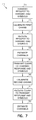
- FIG. 6 is a flow chart illustrating several training and calibration methods according to various embodiments.
- any of the numbers of communication chains discussed may correspond to a number of receive chains, and/or to a number of transmit chains, as desired for particular implementations of the method 611 . Therefore, in light of the previous discussion with respect to the first scheme, it can be seen that a method 611 directed to the operation of various embodiments of the invention disclosed may (optionally) begin with receiving a request to transmit at a first number of communication chains at block 621 and determining one or more transmit power levels and/or receive gain levels associated with the first number of communication chains at block 625 .
- the method 611 may include transmitting a clear to transmit response and a first number of training symbols from the first number of communication chains at block 631 and calibrating some number of transmit and receive chains included in the first number of communication chains at block 635 .
- the method 611 may include transmitting a first number of training symbols corresponding to a first number of communication chains to solicit a response including a second number of training symbols corresponding to a second number of communication chains.
- the method 611 may continue with receiving a clear to transmit response and the first number of training symbols at a second number of communication chains at block 641 and estimating one or more communications channels associated with the second number of communication chains based on the first number of training symbols at block 645 .
- the method 611 may also include transmitting the second number of training symbols and data at block 651 .
- the method 611 may include transmitting a second number of training symbols corresponding to a second number of communication chains in response to receiving a first number of training symbols corresponding to a first number of communication chains.
- the method 611 may include calibrating some number of transmit and receive chains included in the second number of communication chains based on the second number of training symbols at block 655 .
- the method 611 may continue with receiving the second number of training symbols and data at block 661 and estimating one or more communications channels associated with the first number of communication chains based on the second number of training symbols at block 665 .
- FIG. 7 is a flow chart illustrating several alternative training and calibration methods according to various embodiments.
- any of the numbers of communication chains discussed may correspond to a number of receive chains, and/or to a number of transmit chains, as desired for particular implementations of the method 711 . Therefore, in light of the previous discussion with respect to the second scheme, it can be seen that a method 711 directed to the operation of various embodiments of the invention disclosed may (optionally) begin with transmitting a request to transmit and the first number of training symbols at block 721 and calibrating one or more of the first number of communication chains at block 725 . Calibrating the first number of communication chains may occur during a sleep mode.
- the method 711 may also include transmitting a header including a length specification corresponding to the first number of training symbols.
- the method 711 may include transmitting a first number of training symbols corresponding to a first number of communication chains to solicit a response including a second number of training symbols corresponding to a second number of communication chains.
- the method 711 may continue with receiving a request to transmit and the first number of training symbols at block 731 and estimating one or more channels associated with the second number of communication chains at block 735 .
- the method 711 may include transmitting a clear to transmit response and the second number of training symbols at block 741 and calibrating one or more of the second number of communication chains at block 745 . Calibrating the second number of communication chains may occur during a sleep mode.
- the method 711 may include transmitting a second number of training symbols corresponding to a second number of communication chains in response to receiving a first number of training symbols corresponding to a first number of communication chains.
- the method 711 may continue with receiving a clear to transmit response and the second number of training symbols at block 751 and estimating one or more channels associated with the first number of communication chains at block 755 .
- the method 711 may also include transmitting a header including a length specification corresponding to the second number of training symbols.
- a software program can be launched from a computer-readable medium in a computer-based system to execute the functions defined in the software program.
- One of ordinary skill in the art will further understand the various programming languages that may be employed to create one or more software programs designed to implement and perform the methods disclosed herein.
- the programs may be structured in an object-orientated format using an object-oriented language such as Java, Smalltalk, or C++.
- the programs can be structured in a procedure-orientated format using a procedural language, such as assembly or C.
- the software components may communicate using any of a number of mechanisms well-known to those skilled in the art, such as application program interfaces or inter-process communication techniques, including remote procedure calls.
- the teachings of various embodiments are not limited to any particular programming language or environment, including Hypertext Markup Language (HTML) and Extensible Markup Language (XML). Thus, other embodiments may be realized.
- HTML Hypertext Markup Language
- XML Extensible Markup Language
- FIG. 8 is a block diagram of an article 885 according to various embodiments, such as a computer, a memory system, a magnetic or optical disk, some other storage device, and/or any type of electronic device or system.
- the article 885 may comprise a processor 887 coupled to a machine-accessible medium such as a memory 889 (e.g., a memory including an electrical, optical, or electromagnetic conductor) having associated information 891 (e.g., data or computer program instructions), which when accessed, results in a machine (e.g., the processor 887 ) performing such actions as transmitting a second number of training symbols corresponding to a second number of communication chains in response to receiving a first number of training symbols corresponding to a first number of communication chains.
- a memory 889 e.g., a memory including an electrical, optical, or electromagnetic conductor
- information 891 e.g., data or computer program instructions
- Other activities may include receiving a clear to transmit response and the first number of training symbols at the second number of communication chains, and estimating one or more communications channels associated with the second number of communication chains based on the first number of training symbols. Further activities may include transmitting the second number of training symbols and data, and calibrating some number of transmit and receive chains included in the second number of communication chains based on the second number of training symbols.
- an article including a machine-accessible medium having associated information, wherein the information, when accessed, results in a machine performing such activities as transmitting a first number of training symbols corresponding to a first number of communication chains to solicit a response including a second number of training symbols corresponding to a second number of communication chains. Additional activities may include transmitting a request to transmit and the first number of training symbols, and calibrating the first number of communication chains. Further activities may include receiving a clear to transmit response and the second number of training symbols, and estimating one or more channels associated with the first number of communication chains.
- Implementing the apparatus, systems, and methods described herein may result in reducing the overhead used for calibration and training of various devices, including those forming a portion of a MIMO system. For packet sizes of approximately 500-1500 bytes, improvements in efficiency may be on the order of 30%-50%. Thus, this type of operation may in turn provide improved bandwidth utilization, and reduced communication costs.
Abstract
Description
where H is the wireless channel matrix for the uplink; βA1, βA2 and βA3 are the responses of the
where yS1 and yS2 signify the received signal at the output of the
where xS1 and xS2 are the symbols sent to the
where cn and bn are two constants for the n-th subcarrier. To satisfy the condition of reciprocity exactly, cn may be set equal to bn. However, in many embodiments, it may be sufficient that Hd=knHu T, where Hd and Hu T differ by the product of a scalar kn. To satisfy the conditions set by Equations (4) and (5) then, calibration and compensation may be effected at
αA1 C 12βA2 x 0=αA2 C 21βA1 x 0 (6)
Equation (6) may be simplified as follows, since C12=C21 due to reciprocity:
αA1 C 1iβAi x 0=αAi C i1βA1 x 0 (8)
Since C1i=Ci1 due to reciprocity, Equation (8) may be simplified as follows:
The loop may be repeated for each value of i in this manner until all of the chains M have been calibrated.
Claims (20)
Priority Applications (1)
| Application Number | Priority Date | Filing Date | Title |
|---|---|---|---|
| US14/602,416 US9407348B2 (en) | 2003-12-30 | 2015-01-22 | Communication overhead reduction apparatus, systems, and methods |
Applications Claiming Priority (3)
| Application Number | Priority Date | Filing Date | Title |
|---|---|---|---|
| US10/751,001 US8369790B2 (en) | 2003-12-30 | 2003-12-30 | Communication overhead reduction apparatus, systems, and methods |
| US13/758,823 US8948195B2 (en) | 2003-12-30 | 2013-02-04 | Communication overhead reduction apparatus, systems, and methods |
| US14/602,416 US9407348B2 (en) | 2003-12-30 | 2015-01-22 | Communication overhead reduction apparatus, systems, and methods |
Related Parent Applications (1)
| Application Number | Title | Priority Date | Filing Date |
|---|---|---|---|
| US13/758,823 Continuation US8948195B2 (en) | 2003-12-30 | 2013-02-04 | Communication overhead reduction apparatus, systems, and methods |
Publications (2)
| Publication Number | Publication Date |
|---|---|
| US20150195028A1 US20150195028A1 (en) | 2015-07-09 |
| US9407348B2 true US9407348B2 (en) | 2016-08-02 |
Family
ID=34701254
Family Applications (3)
| Application Number | Title | Priority Date | Filing Date |
|---|---|---|---|
| US10/751,001 Active 2029-08-30 US8369790B2 (en) | 2003-12-30 | 2003-12-30 | Communication overhead reduction apparatus, systems, and methods |
| US13/758,823 Expired - Lifetime US8948195B2 (en) | 2003-12-30 | 2013-02-04 | Communication overhead reduction apparatus, systems, and methods |
| US14/602,416 Expired - Lifetime US9407348B2 (en) | 2003-12-30 | 2015-01-22 | Communication overhead reduction apparatus, systems, and methods |
Family Applications Before (2)
| Application Number | Title | Priority Date | Filing Date |
|---|---|---|---|
| US10/751,001 Active 2029-08-30 US8369790B2 (en) | 2003-12-30 | 2003-12-30 | Communication overhead reduction apparatus, systems, and methods |
| US13/758,823 Expired - Lifetime US8948195B2 (en) | 2003-12-30 | 2013-02-04 | Communication overhead reduction apparatus, systems, and methods |
Country Status (1)
| Country | Link |
|---|---|
| US (3) | US8369790B2 (en) |
Families Citing this family (21)
| Publication number | Priority date | Publication date | Assignee | Title |
|---|---|---|---|---|
| US8369790B2 (en) * | 2003-12-30 | 2013-02-05 | Intel Corporation | Communication overhead reduction apparatus, systems, and methods |
| US7873022B2 (en) * | 2004-02-19 | 2011-01-18 | Broadcom Corporation | Multiple input multiple output wireless local area network communications |
| US7596355B2 (en) * | 2004-11-29 | 2009-09-29 | Intel Corporation | System and method capable of closed loop MIMO calibration |
| US8270514B2 (en) | 2005-01-17 | 2012-09-18 | Sharp Kabushiki Kaisha | Communication device |
| US7610017B2 (en) * | 2005-06-09 | 2009-10-27 | Vixs Systems, Inc. | Increased data rate transmissions of a wireless communication |
| WO2007004924A1 (en) * | 2005-07-01 | 2007-01-11 | Telefonaktiebolaget Lm Ericsson (Publ) | A wireless telecommunications system with improved transmission capacity |
| US7778607B2 (en) * | 2005-10-31 | 2010-08-17 | The Mitre Corporation | Echo MIMO: a method for optimal multiple input multiple output channel estimation and matched cooperative beamforming |
| KR100708204B1 (en) * | 2005-11-07 | 2007-04-16 | 삼성전자주식회사 | Method and apparatus for guaranteeing fairness of medium access among stations in wireless lan |
| US7532675B2 (en) * | 2005-12-23 | 2009-05-12 | Intel Corporation | Techniques to time vary pilot locations in wireless networks |
| US9130791B2 (en) | 2006-03-20 | 2015-09-08 | Qualcomm Incorporated | Uplink channel estimation using a signaling channel |
| JP4356756B2 (en) | 2006-04-27 | 2009-11-04 | ソニー株式会社 | Wireless communication system, wireless communication apparatus, and wireless communication method |
| JP4924106B2 (en) | 2006-04-27 | 2012-04-25 | ソニー株式会社 | Wireless communication system, wireless communication apparatus, and wireless communication method |
| JP4775288B2 (en) | 2006-04-27 | 2011-09-21 | ソニー株式会社 | Wireless communication system, wireless communication apparatus, and wireless communication method |
| US7881742B2 (en) * | 2007-01-31 | 2011-02-01 | Qualcomm, Incorporated | Method and apparatus for power control during DTX operation |
| US8792922B2 (en) * | 2007-02-28 | 2014-07-29 | Qualcomm Incorporated | Uplink scheduling for fairness in channel estimation performance |
| US9172455B2 (en) * | 2009-02-13 | 2015-10-27 | Qualcomm Incorporated | Start frame for distributed MIMO |
| US8891464B2 (en) | 2011-09-19 | 2014-11-18 | Redline Innovations Group, Inc. | Architecture, devices and methods for supporting multiple channels in a wireless system |
| WO2014141068A1 (en) * | 2013-03-15 | 2014-09-18 | Celeno Communications (Israel) Ltd. | Self-calibration techniques for implicit beamforming |
| KR20150063886A (en) * | 2013-12-02 | 2015-06-10 | 삼성전기주식회사 | Method for initiating communication of access point and wireless terminal |
| US10172164B2 (en) * | 2016-04-13 | 2019-01-01 | Intel IP Corporation | Spatial reuse with training in RTS-CTS |
| DE102017123459A1 (en) | 2017-10-10 | 2019-04-11 | Dr. Ing. H.C. F. Porsche Aktiengesellschaft | Radiator grille for use in a motor vehicle |
Citations (39)
| Publication number | Priority date | Publication date | Assignee | Title |
|---|---|---|---|---|
| US5515378A (en) | 1991-12-12 | 1996-05-07 | Arraycomm, Inc. | Spatial division multiple access wireless communication systems |
| US5909649A (en) | 1996-01-27 | 1999-06-01 | Motorola, Inc. | Space division multiple access radio communication system and method for allocating channels therein |
| US5936569A (en) | 1997-12-02 | 1999-08-10 | Nokia Telecommunications Oy | Method and arrangement for adjusting antenna pattern |
| US6047189A (en) | 1996-10-11 | 2000-04-04 | Arraycomm, Inc. | Adaptive method for channel assignment in a cellular communication system |
| US6144711A (en) | 1996-08-29 | 2000-11-07 | Cisco Systems, Inc. | Spatio-temporal processing for communication |
| US20020041635A1 (en) | 2000-09-01 | 2002-04-11 | Jianglei Ma | Preamble design for multiple input - multiple output (MIMO), orthogonal frequency division multiplexing (OFDM) system |
| US20020110138A1 (en) | 2000-07-25 | 2002-08-15 | Peter Schramm | Link quality determination of a transmission link in an OFDM transmission system |
| US20020191573A1 (en) | 2001-06-14 | 2002-12-19 | Whitehill Eric A. | Embedded routing algorithms under the internet protocol routing layer of a software architecture protocol stack in a mobile Ad-Hoc network |
| US6549585B2 (en) | 1997-10-06 | 2003-04-15 | At&T Corp | Combined interference cancellation and maximum likelihood decoding of space-time block codes |
| US20030072255A1 (en) | 2001-10-17 | 2003-04-17 | Jianglei Ma | System access and synchronization methods for MIMO OFDM communications systems and physical layer packet and preamble design |
| US20030076777A1 (en) | 2001-09-17 | 2003-04-24 | Stuber Gordon L. | Apparatus and methods for providing efficient space-time structures for preambles, pilots and data for multi-input, multi-output communications systems |
| US6593880B2 (en) | 1996-10-10 | 2003-07-15 | Teratech Corporation | Communication system using geographic position data |
| US20040062302A1 (en) | 2002-09-27 | 2004-04-01 | Ntt Docomo, Inc. | Adaptive equalizing apparatus and program therefor |
| US20040062211A1 (en) | 2002-09-30 | 2004-04-01 | Uhlik Christopher R. | Assigning training sequences based on spatial channels in a wireless communications system |
| US20040131012A1 (en) | 2002-10-04 | 2004-07-08 | Apurva Mody | Methods and systems for sampling frequency offset detection, correction and control for MIMO OFDM systems |
| US20040146018A1 (en) | 2002-10-25 | 2004-07-29 | Walton J. Rodney | Multi-mode terminal in a wireless MIMO system |
| US6771706B2 (en) | 2001-03-23 | 2004-08-03 | Qualcomm Incorporated | Method and apparatus for utilizing channel state information in a wireless communication system |
| US20040151145A1 (en) | 2003-01-30 | 2004-08-05 | Hammerschmidt Joachim S. | Channel estimation for an OFDM transceiver |
| US6795407B2 (en) | 2000-04-22 | 2004-09-21 | Atheros Communications, Inc. | Methods for controlling shared access to wireless transmission systems and increasing throughput of the same |
| US20040192218A1 (en) | 2003-03-31 | 2004-09-30 | Oprea Alexandru M. | System and method for channel data transmission in wireless communication systems |
| US20040190636A1 (en) | 2003-03-31 | 2004-09-30 | Oprea Alexandru M. | System and method for wireless communication systems |
| US6850481B2 (en) | 2000-09-01 | 2005-02-01 | Nortel Networks Limited | Channels estimation for multiple input—multiple output, orthogonal frequency division multiplexing (OFDM) system |
| US20050032478A1 (en) | 2003-08-08 | 2005-02-10 | Stephens Adrian P. | Trained data transmission for communication systems |
| US20050094740A1 (en) | 2003-10-31 | 2005-05-05 | Nokia Corporation | Multiple-antenna partially coherent constellations for multi-carrier systems |
| US20050128953A1 (en) | 2002-10-25 | 2005-06-16 | Wallace Mark S. | Channel calibration for a time division duplexed communication system |
| US20050135403A1 (en) | 2003-10-15 | 2005-06-23 | Qualcomm Incorporated | Method, apparatus, and system for medium access control |
| US20050141540A1 (en) | 2003-12-30 | 2005-06-30 | Qinghua Li | Communication overhead reduction apparatus, systems, and methods |
| US20050143014A1 (en) | 2003-12-29 | 2005-06-30 | Intel Corporation | Antenna subsystem calibration apparatus and methods in spatial-division multiple-access systems |
| US20050141459A1 (en) | 2003-12-29 | 2005-06-30 | Intel Corporation | Apparatus and associated methods to reduce management overhead in a wireless communication system |
| US6965762B2 (en) | 2002-03-01 | 2005-11-15 | Ipr Licensing, Inc. | System and method for antenna diversity using joint maximal ratio combining |
| US6978151B2 (en) | 2001-05-10 | 2005-12-20 | Koninklijke Philips Electronics N.V. | Updating path loss estimation for power control and link adaptation in IEEE 802.11h WLAN |
| US7024163B1 (en) | 2001-09-28 | 2006-04-04 | Arraycomm Llc | Method and apparatus for adjusting feedback of a remote unit |
| US7139340B2 (en) | 2002-06-28 | 2006-11-21 | Hitachi, Ltd. | Robust OFDM carrier recovery methods and apparatus |
| US7194237B2 (en) | 2002-07-30 | 2007-03-20 | Ipr Licensing Inc. | System and method for multiple-input multiple-output (MIMO) radio communication |
| US7430257B1 (en) * | 1998-02-12 | 2008-09-30 | Lot 41 Acquisition Foundation, Llc | Multicarrier sub-layer for direct sequence channel and multiple-access coding |
| US7461164B2 (en) | 2002-02-08 | 2008-12-02 | Dsp Group Inc. | Medium access control with software -and hardware- based components in a wireless network |
| US20150244430A1 (en) * | 2001-04-26 | 2015-08-27 | Genghiscomm Holdings, LLC | Cloud Radio Access Network |
| US20150270882A1 (en) * | 2001-04-26 | 2015-09-24 | Genghiscomm Holdings, LLC | Coordinated Multipoint Systems |
| US20150303950A1 (en) * | 2001-04-26 | 2015-10-22 | Genghiscomm Holdings, LLC | Distributed Software-Defined Radio |
-
2003
- 2003-12-30 US US10/751,001 patent/US8369790B2/en active Active
-
2013
- 2013-02-04 US US13/758,823 patent/US8948195B2/en not_active Expired - Lifetime
-
2015
- 2015-01-22 US US14/602,416 patent/US9407348B2/en not_active Expired - Lifetime
Patent Citations (46)
| Publication number | Priority date | Publication date | Assignee | Title |
|---|---|---|---|---|
| US5515378A (en) | 1991-12-12 | 1996-05-07 | Arraycomm, Inc. | Spatial division multiple access wireless communication systems |
| US5909649A (en) | 1996-01-27 | 1999-06-01 | Motorola, Inc. | Space division multiple access radio communication system and method for allocating channels therein |
| US6144711A (en) | 1996-08-29 | 2000-11-07 | Cisco Systems, Inc. | Spatio-temporal processing for communication |
| US6377631B1 (en) | 1996-08-29 | 2002-04-23 | Cisco Systems, Inc. | Transmitter incorporating spatio-temporal processing |
| US20030072382A1 (en) | 1996-08-29 | 2003-04-17 | Cisco Systems, Inc. | Spatio-temporal processing for communication |
| US6593880B2 (en) | 1996-10-10 | 2003-07-15 | Teratech Corporation | Communication system using geographic position data |
| US6047189A (en) | 1996-10-11 | 2000-04-04 | Arraycomm, Inc. | Adaptive method for channel assignment in a cellular communication system |
| US6549585B2 (en) | 1997-10-06 | 2003-04-15 | At&T Corp | Combined interference cancellation and maximum likelihood decoding of space-time block codes |
| US5936569A (en) | 1997-12-02 | 1999-08-10 | Nokia Telecommunications Oy | Method and arrangement for adjusting antenna pattern |
| US7430257B1 (en) * | 1998-02-12 | 2008-09-30 | Lot 41 Acquisition Foundation, Llc | Multicarrier sub-layer for direct sequence channel and multiple-access coding |
| US6795407B2 (en) | 2000-04-22 | 2004-09-21 | Atheros Communications, Inc. | Methods for controlling shared access to wireless transmission systems and increasing throughput of the same |
| US20020110138A1 (en) | 2000-07-25 | 2002-08-15 | Peter Schramm | Link quality determination of a transmission link in an OFDM transmission system |
| US20020041635A1 (en) | 2000-09-01 | 2002-04-11 | Jianglei Ma | Preamble design for multiple input - multiple output (MIMO), orthogonal frequency division multiplexing (OFDM) system |
| US6850481B2 (en) | 2000-09-01 | 2005-02-01 | Nortel Networks Limited | Channels estimation for multiple input—multiple output, orthogonal frequency division multiplexing (OFDM) system |
| US6771706B2 (en) | 2001-03-23 | 2004-08-03 | Qualcomm Incorporated | Method and apparatus for utilizing channel state information in a wireless communication system |
| US20150303950A1 (en) * | 2001-04-26 | 2015-10-22 | Genghiscomm Holdings, LLC | Distributed Software-Defined Radio |
| US20150270882A1 (en) * | 2001-04-26 | 2015-09-24 | Genghiscomm Holdings, LLC | Coordinated Multipoint Systems |
| US20150244430A1 (en) * | 2001-04-26 | 2015-08-27 | Genghiscomm Holdings, LLC | Cloud Radio Access Network |
| US6978151B2 (en) | 2001-05-10 | 2005-12-20 | Koninklijke Philips Electronics N.V. | Updating path loss estimation for power control and link adaptation in IEEE 802.11h WLAN |
| US20020191573A1 (en) | 2001-06-14 | 2002-12-19 | Whitehill Eric A. | Embedded routing algorithms under the internet protocol routing layer of a software architecture protocol stack in a mobile Ad-Hoc network |
| US20030076777A1 (en) | 2001-09-17 | 2003-04-24 | Stuber Gordon L. | Apparatus and methods for providing efficient space-time structures for preambles, pilots and data for multi-input, multi-output communications systems |
| US7024163B1 (en) | 2001-09-28 | 2006-04-04 | Arraycomm Llc | Method and apparatus for adjusting feedback of a remote unit |
| US20030072255A1 (en) | 2001-10-17 | 2003-04-17 | Jianglei Ma | System access and synchronization methods for MIMO OFDM communications systems and physical layer packet and preamble design |
| US7461164B2 (en) | 2002-02-08 | 2008-12-02 | Dsp Group Inc. | Medium access control with software -and hardware- based components in a wireless network |
| US6965762B2 (en) | 2002-03-01 | 2005-11-15 | Ipr Licensing, Inc. | System and method for antenna diversity using joint maximal ratio combining |
| US7139340B2 (en) | 2002-06-28 | 2006-11-21 | Hitachi, Ltd. | Robust OFDM carrier recovery methods and apparatus |
| US7194237B2 (en) | 2002-07-30 | 2007-03-20 | Ipr Licensing Inc. | System and method for multiple-input multiple-output (MIMO) radio communication |
| US20040062302A1 (en) | 2002-09-27 | 2004-04-01 | Ntt Docomo, Inc. | Adaptive equalizing apparatus and program therefor |
| US20040062211A1 (en) | 2002-09-30 | 2004-04-01 | Uhlik Christopher R. | Assigning training sequences based on spatial channels in a wireless communications system |
| US20040131012A1 (en) | 2002-10-04 | 2004-07-08 | Apurva Mody | Methods and systems for sampling frequency offset detection, correction and control for MIMO OFDM systems |
| US20050128953A1 (en) | 2002-10-25 | 2005-06-16 | Wallace Mark S. | Channel calibration for a time division duplexed communication system |
| US20040146018A1 (en) | 2002-10-25 | 2004-07-29 | Walton J. Rodney | Multi-mode terminal in a wireless MIMO system |
| US20040151145A1 (en) | 2003-01-30 | 2004-08-05 | Hammerschmidt Joachim S. | Channel estimation for an OFDM transceiver |
| US20040192218A1 (en) | 2003-03-31 | 2004-09-30 | Oprea Alexandru M. | System and method for channel data transmission in wireless communication systems |
| US20040190636A1 (en) | 2003-03-31 | 2004-09-30 | Oprea Alexandru M. | System and method for wireless communication systems |
| US7373112B2 (en) | 2003-08-08 | 2008-05-13 | Intel Corporation | Trained data transmission for communication systems |
| US20050032478A1 (en) | 2003-08-08 | 2005-02-10 | Stephens Adrian P. | Trained data transmission for communication systems |
| US20050135403A1 (en) | 2003-10-15 | 2005-06-23 | Qualcomm Incorporated | Method, apparatus, and system for medium access control |
| US20050094740A1 (en) | 2003-10-31 | 2005-05-05 | Nokia Corporation | Multiple-antenna partially coherent constellations for multi-carrier systems |
| US20050141459A1 (en) | 2003-12-29 | 2005-06-30 | Intel Corporation | Apparatus and associated methods to reduce management overhead in a wireless communication system |
| US7206550B2 (en) | 2003-12-29 | 2007-04-17 | Intel Corporation | Antenna subsystem calibration apparatus and methods in spatial-division multiple-access systems |
| US20050143014A1 (en) | 2003-12-29 | 2005-06-30 | Intel Corporation | Antenna subsystem calibration apparatus and methods in spatial-division multiple-access systems |
| US20050141540A1 (en) | 2003-12-30 | 2005-06-30 | Qinghua Li | Communication overhead reduction apparatus, systems, and methods |
| US8948195B2 (en) | 2003-12-30 | 2015-02-03 | Intel Corporation | Communication overhead reduction apparatus, systems, and methods |
| US20130208820A1 (en) | 2003-12-30 | 2013-08-15 | Qinghua Li | Communication overhead reduction apparatus, systems, and methods |
| US8369790B2 (en) | 2003-12-30 | 2013-02-05 | Intel Corporation | Communication overhead reduction apparatus, systems, and methods |
Non-Patent Citations (16)
Also Published As
| Publication number | Publication date |
|---|---|
| US20050141540A1 (en) | 2005-06-30 |
| US20130208820A1 (en) | 2013-08-15 |
| US8369790B2 (en) | 2013-02-05 |
| US8948195B2 (en) | 2015-02-03 |
| US20150195028A1 (en) | 2015-07-09 |
Similar Documents
| Publication | Publication Date | Title |
|---|---|---|
| US9407348B2 (en) | Communication overhead reduction apparatus, systems, and methods | |
| US20050141459A1 (en) | Apparatus and associated methods to reduce management overhead in a wireless communication system | |
| KR102371879B1 (en) | MIMO mode adaptation in MMW WLAN system | |
| US8542589B2 (en) | Method and apparatus for providing beamforming feedback in wireless communication systems | |
| US20100260060A1 (en) | Integrated calibration protocol for wireless lans | |
| US7719993B2 (en) | Downlink transmit beamforming | |
| US8588283B2 (en) | Method and system for frame formats for MIMO channel measurement exchange | |
| US9531498B2 (en) | Link adaptation in a communication network | |
| US7542454B2 (en) | MIMO channel feedback protocols | |
| US7953171B2 (en) | Training symbol format for adaptively power loaded MIMO | |
| US9258070B2 (en) | Simultaneous feedback signaling for dynamic bandwidth selection | |
| US7366245B2 (en) | Calibration in MIMO systems | |
| CN103973353A (en) | Sounding And Steering Protocols For Wireless Communications | |
| JP2008504730A (en) | Method and apparatus for selecting transmission mode based on packet size in communication system with multiple antennas | |
| US11917547B2 (en) | Power save for multi-user (MU) operation | |
| US20210105157A1 (en) | Channel estimation method and apparatus, and communications system | |
| US8913515B2 (en) | Measuring and improving multiuser downlink reception quality in wireless local area networks | |
| US10742273B2 (en) | Link margin procedure for enhanced directional multigigabit (EDMG) | |
| US8605746B2 (en) | Data definition apparatus, systems, and methods | |
| US20230328594A1 (en) | Communication device |
Legal Events
| Date | Code | Title | Description |
|---|---|---|---|
| AS | Assignment |
Owner name: INTEL CORPORATION, CALIFORNIA Free format text: ASSIGNMENT OF ASSIGNORS INTEREST;ASSIGNORS:LI, QINGHUA;LIN, XINTIAN E;REEL/FRAME:034884/0348 Effective date: 20040521 |
|
| FEPP | Fee payment procedure |
Free format text: PAYOR NUMBER ASSIGNED (ORIGINAL EVENT CODE: ASPN); ENTITY STATUS OF PATENT OWNER: LARGE ENTITY |
|
| STCF | Information on status: patent grant |
Free format text: PATENTED CASE |
|
| MAFP | Maintenance fee payment |
Free format text: PAYMENT OF MAINTENANCE FEE, 4TH YEAR, LARGE ENTITY (ORIGINAL EVENT CODE: M1551); ENTITY STATUS OF PATENT OWNER: LARGE ENTITY Year of fee payment: 4 |
|
| FEPP | Fee payment procedure |
Free format text: MAINTENANCE FEE REMINDER MAILED (ORIGINAL EVENT CODE: REM.); ENTITY STATUS OF PATENT OWNER: LARGE ENTITY |