US9411069B1 - Wireless radiation sensor - Google Patents
Wireless radiation sensor Download PDFInfo
- Publication number
- US9411069B1 US9411069B1 US14/842,007 US201514842007A US9411069B1 US 9411069 B1 US9411069 B1 US 9411069B1 US 201514842007 A US201514842007 A US 201514842007A US 9411069 B1 US9411069 B1 US 9411069B1
- Authority
- US
- United States
- Prior art keywords
- ferromagnetic metal
- radiation
- sensor
- sensitive material
- wire
- Prior art date
- Legal status (The legal status is an assumption and is not a legal conclusion. Google has not performed a legal analysis and makes no representation as to the accuracy of the status listed.)
- Active
Links
- 230000005855 radiation Effects 0.000 title claims abstract description 84
- 230000005294 ferromagnetic effect Effects 0.000 claims abstract description 86
- 229910052751 metal Inorganic materials 0.000 claims abstract description 67
- 239000002184 metal Substances 0.000 claims abstract description 67
- 239000000463 material Substances 0.000 claims abstract description 66
- 230000005291 magnetic effect Effects 0.000 claims abstract description 21
- 206010073306 Exposure to radiation Diseases 0.000 claims abstract description 19
- 230000008859 change Effects 0.000 claims abstract description 16
- 239000003153 chemical reaction reagent Substances 0.000 claims description 64
- 230000007246 mechanism Effects 0.000 claims description 35
- 238000001514 detection method Methods 0.000 claims description 30
- XEEYBQQBJWHFJM-UHFFFAOYSA-N Iron Chemical compound [Fe] XEEYBQQBJWHFJM-UHFFFAOYSA-N 0.000 claims description 20
- 229910045601 alloy Inorganic materials 0.000 claims description 19
- 239000000956 alloy Substances 0.000 claims description 19
- 230000005381 magnetic domain Effects 0.000 claims description 13
- 238000000034 method Methods 0.000 claims description 12
- 230000001939 inductive effect Effects 0.000 claims description 10
- 229910052742 iron Inorganic materials 0.000 claims description 6
- 229910017052 cobalt Inorganic materials 0.000 claims description 4
- 239000010941 cobalt Substances 0.000 claims description 4
- GUTLYIVDDKVIGB-UHFFFAOYSA-N cobalt atom Chemical compound [Co] GUTLYIVDDKVIGB-UHFFFAOYSA-N 0.000 claims description 4
- 239000013077 target material Substances 0.000 description 28
- OKKJLVBELUTLKV-UHFFFAOYSA-N Methanol Chemical compound OC OKKJLVBELUTLKV-UHFFFAOYSA-N 0.000 description 18
- 239000007789 gas Substances 0.000 description 10
- 229920003171 Poly (ethylene oxide) Polymers 0.000 description 9
- 239000000126 substance Substances 0.000 description 7
- -1 temperature Substances 0.000 description 7
- 239000000203 mixture Substances 0.000 description 6
- 230000008569 process Effects 0.000 description 6
- 230000008901 benefit Effects 0.000 description 5
- 229920000642 polymer Polymers 0.000 description 5
- 238000010521 absorption reaction Methods 0.000 description 4
- 239000002131 composite material Substances 0.000 description 4
- 230000007423 decrease Effects 0.000 description 4
- 230000000694 effects Effects 0.000 description 4
- 238000005516 engineering process Methods 0.000 description 4
- 230000006870 function Effects 0.000 description 4
- 230000005251 gamma ray Effects 0.000 description 4
- 239000007788 liquid Substances 0.000 description 4
- VNWKTOKETHGBQD-UHFFFAOYSA-N methane Chemical compound C VNWKTOKETHGBQD-UHFFFAOYSA-N 0.000 description 4
- 239000002245 particle Substances 0.000 description 4
- 230000035945 sensitivity Effects 0.000 description 4
- 229920000858 Cyclodextrin Polymers 0.000 description 3
- 239000002360 explosive Substances 0.000 description 3
- 239000011521 glass Substances 0.000 description 3
- 239000000155 melt Substances 0.000 description 3
- 238000012986 modification Methods 0.000 description 3
- 230000004048 modification Effects 0.000 description 3
- 230000036316 preload Effects 0.000 description 3
- 230000004044 response Effects 0.000 description 3
- 229920001450 Alpha-Cyclodextrin Polymers 0.000 description 2
- 241000193738 Bacillus anthracis Species 0.000 description 2
- CERQOIWHTDAKMF-UHFFFAOYSA-N Methacrylic acid Chemical compound CC(=C)C(O)=O CERQOIWHTDAKMF-UHFFFAOYSA-N 0.000 description 2
- 229920002873 Polyethylenimine Polymers 0.000 description 2
- 239000004743 Polypropylene Substances 0.000 description 2
- 229920006362 Teflon® Polymers 0.000 description 2
- 229910002065 alloy metal Inorganic materials 0.000 description 2
- HFHDHCJBZVLPGP-RWMJIURBSA-N alpha-cyclodextrin Chemical compound OC[C@H]([C@H]([C@@H]([C@H]1O)O)O[C@H]2O[C@@H]([C@@H](O[C@H]3O[C@H](CO)[C@H]([C@@H]([C@H]3O)O)O[C@H]3O[C@H](CO)[C@H]([C@@H]([C@H]3O)O)O[C@H]3O[C@H](CO)[C@H]([C@@H]([C@H]3O)O)O3)[C@H](O)[C@H]2O)CO)O[C@@H]1O[C@H]1[C@H](O)[C@@H](O)[C@@H]3O[C@@H]1CO HFHDHCJBZVLPGP-RWMJIURBSA-N 0.000 description 2
- 229940043377 alpha-cyclodextrin Drugs 0.000 description 2
- 238000013473 artificial intelligence Methods 0.000 description 2
- VHRGRCVQAFMJIZ-UHFFFAOYSA-N cadaverine Chemical compound NCCCCCN VHRGRCVQAFMJIZ-UHFFFAOYSA-N 0.000 description 2
- 238000006243 chemical reaction Methods 0.000 description 2
- 239000003795 chemical substances by application Substances 0.000 description 2
- 230000001186 cumulative effect Effects 0.000 description 2
- 239000004205 dimethyl polysiloxane Substances 0.000 description 2
- 239000003814 drug Substances 0.000 description 2
- 238000000605 extraction Methods 0.000 description 2
- 230000004907 flux Effects 0.000 description 2
- SWQJXJOGLNCZEY-BJUDXGSMSA-N helium-3 atom Chemical compound [3He] SWQJXJOGLNCZEY-BJUDXGSMSA-N 0.000 description 2
- 238000002074 melt spinning Methods 0.000 description 2
- 229910001092 metal group alloy Inorganic materials 0.000 description 2
- 239000012621 metal-organic framework Substances 0.000 description 2
- 150000002739 metals Chemical class 0.000 description 2
- 229910000697 metglas Inorganic materials 0.000 description 2
- 229920000609 methyl cellulose Polymers 0.000 description 2
- 239000001923 methylcellulose Substances 0.000 description 2
- 235000010981 methylcellulose Nutrition 0.000 description 2
- 229920000435 poly(dimethylsiloxane) Polymers 0.000 description 2
- 229920001155 polypropylene Polymers 0.000 description 2
- 239000011148 porous material Substances 0.000 description 2
- HFHDHCJBZVLPGP-UHFFFAOYSA-N schardinger α-dextrin Chemical compound O1C(C(C2O)O)C(CO)OC2OC(C(C2O)O)C(CO)OC2OC(C(C2O)O)C(CO)OC2OC(C(O)C2O)C(CO)OC2OC(C(C2O)O)C(CO)OC2OC2C(O)C(O)C1OC2CO HFHDHCJBZVLPGP-UHFFFAOYSA-N 0.000 description 2
- 238000004088 simulation Methods 0.000 description 2
- 238000002470 solid-phase micro-extraction Methods 0.000 description 2
- 238000012546 transfer Methods 0.000 description 2
- XLYOFNOQVPJJNP-UHFFFAOYSA-N water Substances O XLYOFNOQVPJJNP-UHFFFAOYSA-N 0.000 description 2
- 108091023037 Aptamer Proteins 0.000 description 1
- UGFAIRIUMAVXCW-UHFFFAOYSA-N Carbon monoxide Chemical compound [O+]#[C-] UGFAIRIUMAVXCW-UHFFFAOYSA-N 0.000 description 1
- 108020004414 DNA Proteins 0.000 description 1
- 102000053602 DNA Human genes 0.000 description 1
- 108090000790 Enzymes Proteins 0.000 description 1
- 102000004190 Enzymes Human genes 0.000 description 1
- 239000001116 FEMA 4028 Substances 0.000 description 1
- KRHYYFGTRYWZRS-UHFFFAOYSA-N Fluorane Chemical compound F KRHYYFGTRYWZRS-UHFFFAOYSA-N 0.000 description 1
- 241000208152 Geranium Species 0.000 description 1
- WQZGKKKJIJFFOK-GASJEMHNSA-N Glucose Natural products OC[C@H]1OC(O)[C@H](O)[C@@H](O)[C@@H]1O WQZGKKKJIJFFOK-GASJEMHNSA-N 0.000 description 1
- 229920002633 Kraton (polymer) Polymers 0.000 description 1
- 229910052778 Plutonium Inorganic materials 0.000 description 1
- 239000004793 Polystyrene Substances 0.000 description 1
- 108020004682 Single-Stranded DNA Proteins 0.000 description 1
- 229920002125 Sokalan® Polymers 0.000 description 1
- 229910000831 Steel Inorganic materials 0.000 description 1
- 208000007536 Thrombosis Diseases 0.000 description 1
- 229910052770 Uranium Inorganic materials 0.000 description 1
- 239000006096 absorbing agent Substances 0.000 description 1
- 239000000809 air pollutant Substances 0.000 description 1
- 229910000808 amorphous metal alloy Inorganic materials 0.000 description 1
- 238000013528 artificial neural network Methods 0.000 description 1
- 125000004429 atom Chemical group 0.000 description 1
- 229960004853 betadex Drugs 0.000 description 1
- 239000012620 biological material Substances 0.000 description 1
- MMYYTPYDNCIFJU-UHFFFAOYSA-N calix[6]arene Chemical compound C1C(C=2)=CC=CC=2CC(C=2)=CC=CC=2CC(C=2)=CC=CC=2CC(C=2)=CC=CC=2CC(C=2)=CC=CC=2CC2=CC=CC1=C2 MMYYTPYDNCIFJU-UHFFFAOYSA-N 0.000 description 1
- 229910002091 carbon monoxide Inorganic materials 0.000 description 1
- 238000005266 casting Methods 0.000 description 1
- 239000000919 ceramic Substances 0.000 description 1
- 239000007795 chemical reaction product Substances 0.000 description 1
- 239000003245 coal Substances 0.000 description 1
- 239000011248 coating agent Substances 0.000 description 1
- 238000000576 coating method Methods 0.000 description 1
- 238000004891 communication Methods 0.000 description 1
- 230000000295 complement effect Effects 0.000 description 1
- 238000010276 construction Methods 0.000 description 1
- 238000001816 cooling Methods 0.000 description 1
- 230000008878 coupling Effects 0.000 description 1
- 238000010168 coupling process Methods 0.000 description 1
- 238000005859 coupling reaction Methods 0.000 description 1
- 238000013480 data collection Methods 0.000 description 1
- 230000001419 dependent effect Effects 0.000 description 1
- 238000006073 displacement reaction Methods 0.000 description 1
- 229940079593 drug Drugs 0.000 description 1
- UJKWLAZYSLJTKA-UHFFFAOYSA-N edma Chemical compound O1CCOC2=CC(CC(C)NC)=CC=C21 UJKWLAZYSLJTKA-UHFFFAOYSA-N 0.000 description 1
- 229920001971 elastomer Polymers 0.000 description 1
- 244000078673 foodborn pathogen Species 0.000 description 1
- 238000007496 glass forming Methods 0.000 description 1
- 239000008103 glucose Substances 0.000 description 1
- 231100001261 hazardous Toxicity 0.000 description 1
- 229920006158 high molecular weight polymer Polymers 0.000 description 1
- 125000004435 hydrogen atom Chemical group [H]* 0.000 description 1
- 229910000040 hydrogen fluoride Inorganic materials 0.000 description 1
- 230000000155 isotopic effect Effects 0.000 description 1
- 150000002605 large molecules Chemical class 0.000 description 1
- 229920002521 macromolecule Polymers 0.000 description 1
- 238000005259 measurement Methods 0.000 description 1
- 239000006060 molten glass Substances 0.000 description 1
- 239000004081 narcotic agent Substances 0.000 description 1
- 239000003345 natural gas Substances 0.000 description 1
- 229910001172 neodymium magnet Inorganic materials 0.000 description 1
- 239000011824 nuclear material Substances 0.000 description 1
- 244000052769 pathogen Species 0.000 description 1
- 230000035699 permeability Effects 0.000 description 1
- 230000002085 persistent effect Effects 0.000 description 1
- 230000000704 physical effect Effects 0.000 description 1
- OYEHPCDNVJXUIW-UHFFFAOYSA-N plutonium atom Chemical compound [Pu] OYEHPCDNVJXUIW-UHFFFAOYSA-N 0.000 description 1
- 239000002574 poison Substances 0.000 description 1
- 231100000614 poison Toxicity 0.000 description 1
- 229920002338 polyhydroxyethylmethacrylate Polymers 0.000 description 1
- 230000002285 radioactive effect Effects 0.000 description 1
- 239000012857 radioactive material Substances 0.000 description 1
- 230000004043 responsiveness Effects 0.000 description 1
- 230000000630 rising effect Effects 0.000 description 1
- 239000008279 sol Substances 0.000 description 1
- 239000007787 solid Substances 0.000 description 1
- 238000001228 spectrum Methods 0.000 description 1
- 238000009987 spinning Methods 0.000 description 1
- 239000010959 steel Substances 0.000 description 1
- 239000000758 substrate Substances 0.000 description 1
- 239000013076 target substance Substances 0.000 description 1
- 230000008685 targeting Effects 0.000 description 1
- 238000012360 testing method Methods 0.000 description 1
- 239000003053 toxin Substances 0.000 description 1
- 231100000765 toxin Toxicity 0.000 description 1
- 108700012359 toxins Proteins 0.000 description 1
- JFALSRSLKYAFGM-UHFFFAOYSA-N uranium(0) Chemical compound [U] JFALSRSLKYAFGM-UHFFFAOYSA-N 0.000 description 1
- 238000012795 verification Methods 0.000 description 1
- 239000012855 volatile organic compound Substances 0.000 description 1
- 239000002699 waste material Substances 0.000 description 1
- 239000003403 water pollutant Substances 0.000 description 1
- 238000004804 winding Methods 0.000 description 1
- 239000010457 zeolite Substances 0.000 description 1
Images


Classifications
-
- G—PHYSICS
- G01—MEASURING; TESTING
- G01T—MEASUREMENT OF NUCLEAR OR X-RADIATION
- G01T1/00—Measuring X-radiation, gamma radiation, corpuscular radiation, or cosmic radiation
-
- G—PHYSICS
- G01—MEASURING; TESTING
- G01V—GEOPHYSICS; GRAVITATIONAL MEASUREMENTS; DETECTING MASSES OR OBJECTS; TAGS
- G01V5/00—Prospecting or detecting by the use of nuclear radiation, e.g. of natural or induced radioactivity
- G01V5/0008—Detecting hidden objects, e.g. weapons, explosives
-
- G—PHYSICS
- G01—MEASURING; TESTING
- G01N—INVESTIGATING OR ANALYSING MATERIALS BY DETERMINING THEIR CHEMICAL OR PHYSICAL PROPERTIES
- G01N27/00—Investigating or analysing materials by the use of electric, electrochemical, or magnetic means
- G01N27/72—Investigating or analysing materials by the use of electric, electrochemical, or magnetic means by investigating magnetic variables
- G01N27/80—Investigating or analysing materials by the use of electric, electrochemical, or magnetic means by investigating magnetic variables for investigating mechanical hardness, e.g. by investigating saturation or remanence of ferromagnetic material
-
- G—PHYSICS
- G01—MEASURING; TESTING
- G01N—INVESTIGATING OR ANALYSING MATERIALS BY DETERMINING THEIR CHEMICAL OR PHYSICAL PROPERTIES
- G01N33/00—Investigating or analysing materials by specific methods not covered by groups G01N1/00 - G01N31/00
- G01N33/20—Metals
- G01N33/202—Constituents thereof
- G01N33/2022—Non-metallic constituents
- G01N33/2025—Gaseous constituents
-
- G01N33/203—
-
- G—PHYSICS
- G01—MEASURING; TESTING
- G01T—MEASUREMENT OF NUCLEAR OR X-RADIATION
- G01T3/00—Measuring neutron radiation
-
- G—PHYSICS
- G01—MEASURING; TESTING
- G01N—INVESTIGATING OR ANALYSING MATERIALS BY DETERMINING THEIR CHEMICAL OR PHYSICAL PROPERTIES
- G01N33/00—Investigating or analysing materials by specific methods not covered by groups G01N1/00 - G01N31/00
- G01N2033/0093—Investigating or analysing materials by specific methods not covered by groups G01N1/00 - G01N31/00 radioactive materials
-
- G—PHYSICS
- G01—MEASURING; TESTING
- G01N—INVESTIGATING OR ANALYSING MATERIALS BY DETERMINING THEIR CHEMICAL OR PHYSICAL PROPERTIES
- G01N27/00—Investigating or analysing materials by the use of electric, electrochemical, or magnetic means
- G01N27/72—Investigating or analysing materials by the use of electric, electrochemical, or magnetic means by investigating magnetic variables
-
- G—PHYSICS
- G01—MEASURING; TESTING
- G01N—INVESTIGATING OR ANALYSING MATERIALS BY DETERMINING THEIR CHEMICAL OR PHYSICAL PROPERTIES
- G01N33/00—Investigating or analysing materials by specific methods not covered by groups G01N1/00 - G01N31/00
- G01N33/0004—Gaseous mixtures, e.g. polluted air
- G01N33/0009—General constructional details of gas analysers, e.g. portable test equipment
- G01N33/0027—General constructional details of gas analysers, e.g. portable test equipment concerning the detector
- G01N33/0036—Specially adapted to detect a particular component
- G01N33/0057—Specially adapted to detect a particular component for warfare agents or explosives
-
- Y—GENERAL TAGGING OF NEW TECHNOLOGICAL DEVELOPMENTS; GENERAL TAGGING OF CROSS-SECTIONAL TECHNOLOGIES SPANNING OVER SEVERAL SECTIONS OF THE IPC; TECHNICAL SUBJECTS COVERED BY FORMER USPC CROSS-REFERENCE ART COLLECTIONS [XRACs] AND DIGESTS
- Y10—TECHNICAL SUBJECTS COVERED BY FORMER USPC
- Y10T—TECHNICAL SUBJECTS COVERED BY FORMER US CLASSIFICATION
- Y10T436/00—Chemistry: analytical and immunological testing
- Y10T436/25—Chemistry: analytical and immunological testing including sample preparation
- Y10T436/25875—Gaseous sample or with change of physical state
Definitions
- This disclosure relates to the field of sensors for detecting radiation. More particularly, this disclosure relates to an inexpensive, highly sensitive radiation sensor having a sensing element capable of being embedded in unobtrusive objects and/or interrogated wirelessly.
- a radiation sensor includes a ferromagnetic metal and a radiation sensitive material coupled to the ferromagnetic metal.
- the radiation sensitive material is operable to change a tensile stress of the ferromagnetic metal upon exposure to radiation.
- the ferromagnetic metal is an amorphous wire.
- the amorphous wire in certain embodiments is composed of a cobalt and/or iron based alloy. In preferred embodiments, the amorphous wire is melt extracted.
- the senor further includes a detection mechanism having an inducing mechanism to induce alternating magnetic domains in the ferromagnetic metal and a sensing mechanism to detect changes in magnetic switching characteristics of the ferromagnetic metal caused by the inducing mechanism and changes in the tensile stress of the ferromagnetic metal caused by exposure of the radiation sensitive material to radiation.
- the sensing mechanism detects changes in induced peaks along a time waveform resulting from the induced alternating magnetic domains in the ferromagnetic metal and changes in the tensile stress of the ferromagnetic metal; the detection mechanism is provided in a separate unit from the ferromagnetic metal and the radiation sensitive material; and/or no electrical components are physically connected to the radiation sensor.
- the radiation sensitive material is directly coupled to the ferromagnetic metal.
- the radiation sensitive material is operable to emit a gas upon exposure to radiation and the radiation sensitive material is indirectly coupled to the ferromagnetic metal via a molecular recognition reagent operable to change the tensile stress of the ferromagnetic metal upon exposure of the molecular recognition reagent to the emitted gas from the radiation sensitive material.
- a radiation sensor includes a ferromagnetic metal having a tensile stress that is operable to change upon exposure to radiation and a detection mechanism.
- the detection mechanism includes an inducing mechanism to induce alternating magnetic domains in the ferromagnetic metal and a sensing mechanism to detect changes in magnetic switching characteristics of the ferromagnetic metal caused by the inducing mechanism and changes in the tensile stress of the ferromagnetic metal caused by exposure of the ferromagnetic metal to radiation.
- the ferromagnetic metal is an amorphous material composed of an iron-based alloy.
- the sensing mechanism detects changes in induced peaks along a time waveform resulting from the induced alternating magnetic domains in the ferromagnetic metal and changes in the tensile stress of the ferromagnetic metal; the detection mechanism is provided in a separate unit from the ferromagnetic metal; and/or no electrical components are physically connected to the ferromagnetic metal.
- a method of detecting radiation in a target device includes providing a sensor element including a ferromagnetic metal and a radiation sensitive material coupled to the ferromagnetic metal; placing the sensor element in proximity to or inside the target device such that the radiation sensitive material changes a tensile stress of the ferromagnetic metal upon exposure to radiation; and detecting a change in magnetic switching characteristics of the ferromagnetic metal resulting from the change in tensile stress imparted by the radiation sensitive material.
- the detecting step is performed by a detection mechanism configured to wirelessly interrogate the sensor element.
- the radiation sensitive material is operable to emit a gas upon exposure to radiation and the radiation sensitive material is indirectly coupled to the ferromagnetic metal via a molecular recognition reagent operable to change the tensile stress of the ferromagnetic metal upon exposure of the molecular recognition reagent to the emitted gas from the radiation sensitive material.
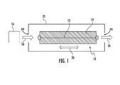
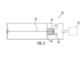
- FIGS. 1 and 2 depict different embodiments of a sensing element having a ferromagnetic wire coupled with a molecular recognition reagent according to the disclosure
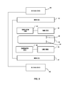
- FIG. 3 depicts a schematic illustration of a sensing element detection mechanism according to the present disclosure
- FIGS. 4A-4C depict peak height detection graphs for detecting methanol using a variety of molecular recognition reagents according to the disclosure.
- FIG. 5 depicts an alternate embodiment of a radiation sensor according to the disclosure.
- this technology may be used in small, low-cost chemical sensors that have applications in many fields such as detecting materials used in making explosives, chemical and biological warfare agents, volatile organic compounds, poisons and toxins, diagnostic exhaled gases, temperature, waste stream contents, air and water pollutants and pathogens, food-borne pathogens, exhaled gases for diagnostics, pharmaceuticals and drugs (including narcotics), cadaverine, diaper contents, moisture, glucose (e.g., blood clot prediction), hazardous gases (e.g., carbon monoxide/natural gas for home detection, methane for coal mine safety, etc.), and countless other chemical substances for countless applications.
- a particular substance being detected is referred to herein as a “target material.”
- the device or housing that potentially contains one or more target materials is referred to herein as a “target device.”
- the sensor of the present disclosure includes a sensing element 10 that employs a ferromagnetic metal 12 coupled to a porous or perforated molecular recognition reagent 14 .
- the ferromagnetic metal in certain embodiments is configured as a mounted wire 12 and the molecular recognition reagent 14 is disposed around the wire.
- the molecular recognition reagent 14 could be coated onto the wire.
- a ribbon construction for the ferromagnetic metal may also be utilized within the spirit of the present disclosure.
- the thickness of the molecular recognition reagent 14 in FIG. 1 has been greatly exaggerated with respect to the ferromagnetic wire 12 .
- the wire 12 will be about 30 to about 100 microns in diameter and the molecular recognition reagent 14 will have a thickness greater than the wire 12 .
- molecular recognition reagent 14 could refer to a specific material or a composite of more than one material.
- the sensing element 10 is placed in proximity to a target device 16 such that the molecular recognition reagent 14 is exposed to vapor or liquid from the target material if the target material is present in the device 16 .
- the sensing element 10 may be disposed in a flow housing 20 having vent holes 29 such that the target material of the target device 16 flows through the housing 20 and past the sensing element 10 as indicated by arrows 26 .
- the molecular recognition reagent 14 is characterized by its affinity for gaseous or liquid components of particular target materials, and its ability to exhibit a large volume change per unit of the target material absorbed.
- the molecular recognition reagent 14 expands upon exposure to the target material, which imposes stress on the ferromagnetic wire 12 in both directions indicated by arrow 28 .
- the molecular recognition reagent 14 contracts upon exposure to the target material such that the pre-stressed wire 12 loses tension upon exposure to the target material.
- the sensing element 10 exploits the fact that, when subjected to alternating magnetic fields, the magnetic field strength and switching speed of the ferromagnetic wire 12 varies as a function of tensile stress in the ferromagnetic wire 12 caused by the volume change of the molecular recognition reagent 14 .
- the sensing element 10 will employ an array of ferromagnetic wires 12 coupled to a diverse set of molecular recognition reagents 14 such that each wire 12 will respond differently to each type or combination of target materials absorbed by the molecular recognition reagents 14 .
- a neural network or other type of artificial intelligence based tool may then be employed to analyze and interpret the changes in the magnetic properties of the wires 12 to identify the presence of the target materials.
- the sensor employs computer learning algorithms that will detect different responses of all the wire/reagent combinations and will continually improve as new data regarding the detection of various materials becomes available. As each wire 12 responds differently to each target material, an effective “fingerprint” for each material is generated and the artificial intelligence tool is utilized to interpret the fingerprint and identify the target materials in the target device.
- the ferromagnetic wire 12 is an amorphous wire constructed from a ferromagnetic alloy having one or more glass forming components.
- the amorphous wire is preferably a Cobalt (Co) and/or Iron (Fe) based alloy with representative compositions including Fe 77.5 Si 7.5 B 15 , Co 80 Si 10 B 10 , Fe 73.5 CuNb 3 Si 13.5 B 9 , Co 68.15 Fe 4.35 Si 12.5 B 15 , and Co 80.9 Fe 4.4 Nb 4.5 Si 8.7 B 1.5 with a diameter of about 30 to 100 microns.
- an array of sensing elements 10 may include wires of varying alloys and/or diameters including diameters from about 5 to 125 microns.
- the amorphous characteristic of the wire 12 is produced during the alloy casting operation by rapid cooling from the molten to solid state. As a result, the material has a disordered atomic-scale (noncrystalline) structure. This noncrystalline structure leads to a higher tensile strength than that of material with an orderly structure.
- the amorphous wire 12 has high magnetic susceptibility with low coercivity and high electrical resistance. Thus, the magnetic domains of the wires 12 can be switched when subjected to very small alternating magnetic fields. In addition, the amorphous wire magnetic domain switching properties are sensitive to stress. These properties of the amorphous ferromagnetic wire 12 enable the sensing applications of the disclosed sensors as further described below.
- the amorphous wire 12 is preferably made using a melt extraction process, which forms the wire by passing a sharp spinning blade through a pool of molten alloy metal.
- the amorphous wire 12 could be made using the so-called Taylor process, which forms the wire by drawing it from a molten glass vial containing the alloy metal. Wires 12 made from the two processes are quite distinctive from each other.
- the Taylor wire has a glass coating, which melt extraction wire does not have. Glass-coated Taylor wire can also be wound in long lengths whereas melt extracted wire cannot be readily spooled and is generally only available in short lengths up to about 2 meters. In effect, melt extracted wire is less uniform than glass-coated Taylor wire, which can cause calibration differences between different sensing elements.
- melt extracted wire over Taylor wire has a greater sensitivity to tension (sensitivity of the melt extracted wire is believed to be over three times greater than the sensitivity of amorphous wire made using the Taylor process), which enables detection of smaller force changes without compromising the size of the sensing element 10 .
- a preload or pre-stretch (estimated to be up to about 12 grams) is needed to eliminate non-responsiveness of the sensing element 10 (i.e., small increases in tension in insufficiently pre-stretched Taylor wire does not produce a corresponding change in detected peak height).
- melt extracted amorphous wire 12 results in sensor de-calibration for applications where the sensor is deployed for extended periods of time.
- Use of melt extracted amorphous wire eliminates or significantly reduces this preload requirement.
- a third benefit of using melt extracted amorphous wire as opposed to Taylor wire is that the melt extracted wire has a higher toleration to stress without de-calibration.
- the amorphous wire 12 is constructed using a modified melt spinning process known as “rotating water bath melt spinning” which involves the streaming of a fine jet of molten alloy into a flow of cold water such that the alloy rapidly solidifies and vitrifies.
- Wire 12 made using this process typically has a diameter of about 80-120 microns and exhibits similar characteristics to melt extracted wire although it is not as sensitive.
- the molecular recognition reagents 14 are chosen from reactive materials that are operable to expand upon exposure and/or absorption of vapor and/or liquid from the target materials.
- the space from which the molecular recognition reagents are chosen is large, and the choice generally depends on the particular target substance (e.g., explosive, chemical or biological warfare agent, pharmaceutical, moisture, etc.) that the sensor is intended to detect and the environment conditions in which the device is to be used.
- target substance e.g., explosive, chemical or biological warfare agent, pharmaceutical, moisture, etc.
- Such molecular recognition reagents include, but are not limited to high molecular-weight polymers, solid-phase microextraction (SPME) materials, metal-organic frameworks (MOFs), immobilized antibodies, classical zeolites, and other porous polymers and metals and combinations thereof.
- molecular recognition reagents include, without limitation, the following: polyacrylic acid (PAA), polyhydroxyethyl methacrylate, dimethacrylate (EDMA), methacrylic acid (MAA), methyl cellulose, polyethyleneimine (PEI), polyethylene oxide (PEO), polypropylene (PP), polystyrene (PS), polydimethylsiloxane (PDMS), Calix[6]arene (Cal[6]), Heptakis(6-O-tert-butyldimethylsilyl-2,3-di-O-acetyl)- ⁇ -cyclodextrin (cyclodextrin or CD), electrospun polymers, Kraton® polymers (a synthetic replacement for rubber), and composites thereof.
- PAA polyacrylic acid
- EDMA dimethacrylate
- MAA methacrylic acid
- MAA methacrylic acid
- methyl cellulose polyethyleneimine
- PEO polyethylene oxide
- PP polypropy
- the sensing element 10 will preferably employ a diverse set of molecular recognition reagents 14 such that each wire 12 will respond differently to each type of target material absorbed by the molecular recognition reagents 14 .
- the particular configuration of the molecular recognition reagents 14 may vary based on the particular target material to be detected. In this regard, the choice of particular molecular recognition reagents 14 is generally based on considerations such as pore size, pore shape, polarity, etc. as compared to the target materials being detected.
- the molecular recognition reagent may include an imprintable polymer having a “lock and key” arrangement for targeting the particular shape of anthrax molecules.
- the reagent surface and volume includes specific geometric shapes complementary to the shapes of targeted particles.
- molecular recognition reagents 14 may also be fabricated from biological materials such as enzymes, antibodies, and aptamers (small single-stranded DNA or RNA molecules) to have lock-and-key relationships with specific substrates. Also, regarding molecular recognition reagents 14 made from composite materials, some of the materials as identified above are used at least in part to improve the ability to fabricate the molecular recognition reagents 14 . This is particularly true of a cyclodextrin/poly(ethylene oxide) (CD/PEO) mixture.
- CD/PEO cyclodextrin/poly(ethylene oxide)
- CD by itself is difficult to be machined into a molecular recognition reagent 14 of a proper shape and size from a pressed disk due to its friability, but addition of a certain amount of PEO makes the material much more workable.
- the composite reagents are physical mixtures—that is, they are typically mixed and pressed rather than reacted—countless combinations of molecular recognition reagents 14 are possible, such as the CD/PEO mixture, to detect each different target material.
- FIG. 2 an alternate embodiment of a sensing element 30 is shown in which the molecular recognition reagent 34 is secured to both the ferromagnetic wire 32 and a fixed support 40 .
- the molecular recognition reagent 34 expands away from the fixed support 40 which imposes stress on the ferromagnetic wire 32 in one direction as indicated by arrow 38 .
- the ferromagnetic wire is placed under tension through the use of a tension inducing mechanism such as a spring such that, when the molecular recognition reagent 34 expands upon absorption of a target material 36 , the molecular recognition reagent relieves the tension generated by the tension inducing mechanism.
- a sensing element substantially as described above is placed in proximity to a target device such that the molecular recognition reagent of the sensing element expands upon absorption of vapor or liquid from a target material while an inducing mechanism is used to induce alternating magnetic domains in the ferromagnetic wire of the sensor.
- the expansion of the molecular recognition reagent changes a tensile stress upon the ferromagnetic wire, and a detection mechanism is used to detect changes in the switching properties of the ferromagnetic wire as a function of changes in the tensile stress of the wire.
- FIG. 3 schematically illustrates a sensor 50 according to the present disclosure where one or more sensing elements 54 are detected by a detection mechanism composed of a system of at least one drive coil 52 and at least one pickup/sensing coil 56 .
- Sensor 50 includes the sensing elements 54 positioned such that changes in the magnetic switching characteristics of the sensing elements 54 caused by changes in the mechanical stress imposed on the wire by the molecular recognition reagent is detected by one or more pickup/sensing coils 56 .
- An alternating current in the drive coil 52 creates the magnetic field, which continually reverses the magnetic domains in the amorphous wire of the sensing elements 54 .
- Reversal of the magnetic domains is detected with the pickup coil 56 as a peak, which changes height based on tensile stress applied to the ferromagnetic wires by the molecular recognition reagents.
- target materials are detected by detecting changes in induced peaks along a time waveform resulting from both the induced alternating domains in the ferromagnetic wire 12 and changes in the tensile stress of the wire 12 caused by exposure of the target material to the molecular recognition reagent 14 coupled to wire 12 .
- the pickup coils 56 are positioned above and around the sensing elements 54 . However, orientation of the pickup coils 56 may vary as desired based on the flux line being detected.
- one or more cancellation coils 58 may also be provided that are wired in an opposite direction from pickup coil 56 . Cancellation coil 58 detects a similar drive coil magnetic field but does not detect a significant amount of the signal produced by switching of the ferromagnetic wire of sensing elements 54 . The purpose of the cancellation coil is to cancel most of the magnetic field produced by the drive coils and eddy currents caused by the drive fields in conducting objects near the pickup coils 56 .
- an offsetting direct current bias field generated by DC bias coils 60 may also be employed by the detection mechanism such that the switching of the magnetic domains of each sensing element occurs at slightly different periods along the time domain. This allows the time domain of each sensing element to be isolated for easier measurements of the peak height of each individual sensor by the pickup coils 56 .
- Different configurations of the bias coil set 60 may be used such as a Maxwell coil or a solenoid with varied coil winding density.
- Sensing element 54 , drive coil 52 , pickup coil 56 , cancellation coil 58 (if used), and DC bias coil 60 (if used) may be housed within a single unit sensor having a power source and wired or wireless communication means for transmitting data acquired from the sensing element 54 , or the drive coil 52 , pickup coil 56 , cancellation coil 58 (if used), and DC bias coil 60 (if used) may be provided in a separate unit from the sensing element 54 .
- the sensing element does not require radioactive sources and, in embodiments where the drive 52 and pickup coils 56 are provided in a separate unit from the sensing element 54 , the sensing element does not require any type of physical power source or data transfer connection. Further one pickup coil is capable of detecting multiple sensing elements having various molecular recognition reagents without tedious alignment of the sensing elements. Thus, the sensor is small, inexpensive, and portable while offering the benefits of rapid detection as well as being highly selective and sensitive.
- FIGS. 4A-4C detection of methanol vapor entrained in a stream of air as an exemplary target material is shown when using a sensing element having various molecular recognition reagents.
- the molecular recognition reagent is methyl cellulose.
- FIG. 4B the response to methanol of sensing element having a molecular recognition reagent composed of 100% polyethylene oxide (PEO) is provided, whereas FIG. 4C provides the response to methanol where the molecular recognition reagent is composed of 40% ⁇ -cyclodextrin and 60% PEO.
- PEO polyethylene oxide
- a sensing element having 100% ⁇ -cyclodextrin as the molecular recognition reagent is believed not to substantially respond to methanol (i.e., does not create tension in the amorphous wire).
- the heights of the peaks in the figures are dependent on the speed at which the amorphous wire domains reverse and the strength of the field produced by the wire.
- tension is applied to the wire upon absorption of the methanol vapor by the particular molecular recognition reagent, the permeability of the amorphous wire decreases and the domain switching slows.
- the amplitude of the field produced by the wire may decrease. This causes the peak current in the pick-up coil 56 of FIG. 3 to decrease with the increase in tension, which is proportional to the amount and type of target material absorbed by the molecular recognition reagent. Slopes and shapes of the falling and rising signals, delay times, and peak heights detected by the pick-up coil may all be useful in determining the identity and concentration of a target and establishing a “fingerprint” for various target materials.
- sensing element 10 may also be used to detect radiation 16 by coupling the ferromagnetic metal wire 12 to a molecular recognition reagent 14 that changes dimensions as a result of exposure to radiation.
- the ferromagnetic metal wire 12 is coupled to a molecular recognition reagent/radiation sensitive material 14 that is operable to impose a change in stress on the wire 12 upon exposure to radiation.
- housing 20 preferably provides protection to the sensing element 10 from mechanical or chemical damage but is fabricated from a material that is otherwise transparent to the radiation being detected.
- vent holes 29 in the housing 20 these vent holes 29 may be omitted when the “target” is radiation 16 .
- the presence of radiation is then able to be detected using a detection mechanism as described above by detecting changes in induced peaks along a time waveform resulting from induced alternating domains in the ferromagnetic wire 12 and changes in the tensile stress of the wire 12 caused by exposure of radiation to the radiation sensitive material 14 coupled to wire 12 .
- the radiation sensitive material 14 is operable to expand upon exposure to radiation by using a material in which radiation creates voids/bubbles in the radiation sensitive material, which would impose additional stress upon the wire 12 .
- the radiation sensitive material may be selected from materials that lose mechanical strength and/or are damaged upon exposure to radiation, which would cause a pre-stressed wire 12 coupled to the radiation sensitive material to contract/relax.
- the radiation sensitive material is chosen from a material that permanently expands or contracts upon exposure to radiation (e.g., steels) such that exposure to any radiation could be detected.
- the wire 12 could be coupled to a radiation sensitive material that gradually expands/contracts upon exposure to radiation (e.g., teflons) to provide a record of cumulative radiation exposure.
- radiation e.g., teflons
- the effects of radiation on various classes of materials are generally known from the field of radiation materials science. Thus, selection of an appropriate radiation sensitive material may be taken from materials as taught in this field to change the stress of wire 12 as desired.
- the radiation sensitive material is selected from a material that produces a gas upon exposure to radiation (e.g., teflons produce hydrogen fluoride upon exposure to radiation) such that the gas produced by the radiation sensitive material is operable to change a tensile stress of the wire 12 upon exposure of the molecular recognition reagent 14 to the gas emitted from the radiation sensitive material.
- a radiation shield 21 is preferably provided to protect the chemical sensing element 10 from radiation damage.
- the radiation sensing element is operable to distinguish between gamma rays and neutrons by exploiting the fact that gamma rays are increasingly absorbed as the atomic number of an atom increases (lead is an example of a good gamma ray absorber) while neutrons are most efficiently scattered by hydrogen atoms.
- a sensing device for efficiently distinguishing neutrons from gamma rays is possible upon selection of appropriate radiation sensitive materials of the sensing elements that react differently to gamma rays and neutrons.
- the ferromagnetic metal of the sensing element itself may be configured to incur radiation-induced changes in the ferromagnetic metal alloy, including changes in the alloy's magnetic and physical properties.
- the ferromagnetic metal is operable to function as a neutron sensor as a result of the radiation-induced changes in the magnetic properties of an amorphous alloy brought about by the impinging neutrons and by energetic charged particles created from 10 B(n, ⁇ ) 7 Li reactions as described, for example, in “Effects of Neutron Irradiation on Nd—Fe—B Magnetic Properties,” IEEE Transactions on Magnetics, 24 (1988) 2016 (J. R.
- amorphous ferromagnetic metal alloy itself functions as the radiation sensitive material would be especially attractive for covert applications as the sensing element could assume any discrete structure (e.g., common objects such as a screw) so it could be dropped off at a suspect location and then later retrieved to test for radiation exposure.
- this embodiment can be manufactured using any technique that preserves the composition and amorphous nature of the material while not requiring an additional radiation sensitive material or molecular recognition reagent to be coupled to the alloy.
- the sensor would require no on-board power sources or physical connections for power or data transfer. The changes in magnetic properties of the alloy would be persistent and cumulative, making this configuration also attractive as radiation sensitive tags and seals.
Abstract
Description
Claims (18)
Priority Applications (1)
| Application Number | Priority Date | Filing Date | Title |
|---|---|---|---|
| US14/842,007 US9411069B1 (en) | 2013-03-15 | 2015-09-01 | Wireless radiation sensor |
Applications Claiming Priority (3)
| Application Number | Priority Date | Filing Date | Title |
|---|---|---|---|
| US13/832,873 US8871523B1 (en) | 2013-03-15 | 2013-03-15 | Wireless sensor for detecting explosive material |
| US14/493,811 US9255920B1 (en) | 2013-03-15 | 2014-09-23 | Wireless sensor |
| US14/842,007 US9411069B1 (en) | 2013-03-15 | 2015-09-01 | Wireless radiation sensor |
Related Parent Applications (1)
| Application Number | Title | Priority Date | Filing Date |
|---|---|---|---|
| US14/493,811 Continuation-In-Part US9255920B1 (en) | 2013-03-15 | 2014-09-23 | Wireless sensor |
Publications (1)
| Publication Number | Publication Date |
|---|---|
| US9411069B1 true US9411069B1 (en) | 2016-08-09 |
Family
ID=56556413
Family Applications (1)
| Application Number | Title | Priority Date | Filing Date |
|---|---|---|---|
| US14/842,007 Active US9411069B1 (en) | 2013-03-15 | 2015-09-01 | Wireless radiation sensor |
Country Status (1)
| Country | Link |
|---|---|
| US (1) | US9411069B1 (en) |
Citations (8)
| Publication number | Priority date | Publication date | Assignee | Title |
|---|---|---|---|---|
| US5821129A (en) | 1997-02-12 | 1998-10-13 | Grimes; Craig A. | Magnetochemical sensor and method for remote interrogation |
| US6270591B2 (en) | 1995-12-27 | 2001-08-07 | Inst De Fizica Tehnica | Amorphous and nanocrystalline glass-covered wires |
| US6393921B1 (en) | 1999-05-13 | 2002-05-28 | University Of Kentucky Research Foundation | Magnetoelastic sensing apparatus and method for remote pressure query of an environment |
| US20060032289A1 (en) | 2004-08-11 | 2006-02-16 | Pinnaduwage Lal A | Non-optical explosive sensor based on two-track piezoresistive microcantilever |
| US20060231420A1 (en) | 2005-04-19 | 2006-10-19 | The Regents Of The University Of California | Explosives detection sensor |
| US7694346B2 (en) | 2004-10-01 | 2010-04-06 | Board Of Regents Of The Nevada System Of Higher Education On Behalf Of The University Of Nevada | Cantilevered probe detector with piezoelectric element |
| US7824619B1 (en) | 2004-06-07 | 2010-11-02 | Ari Aviram | Molecular sensors for explosives |
| US8871523B1 (en) * | 2013-03-15 | 2014-10-28 | Consolidated Nuclear Security, LLC | Wireless sensor for detecting explosive material |
-
2015
- 2015-09-01 US US14/842,007 patent/US9411069B1/en active Active
Patent Citations (8)
| Publication number | Priority date | Publication date | Assignee | Title |
|---|---|---|---|---|
| US6270591B2 (en) | 1995-12-27 | 2001-08-07 | Inst De Fizica Tehnica | Amorphous and nanocrystalline glass-covered wires |
| US5821129A (en) | 1997-02-12 | 1998-10-13 | Grimes; Craig A. | Magnetochemical sensor and method for remote interrogation |
| US6393921B1 (en) | 1999-05-13 | 2002-05-28 | University Of Kentucky Research Foundation | Magnetoelastic sensing apparatus and method for remote pressure query of an environment |
| US7824619B1 (en) | 2004-06-07 | 2010-11-02 | Ari Aviram | Molecular sensors for explosives |
| US20060032289A1 (en) | 2004-08-11 | 2006-02-16 | Pinnaduwage Lal A | Non-optical explosive sensor based on two-track piezoresistive microcantilever |
| US7694346B2 (en) | 2004-10-01 | 2010-04-06 | Board Of Regents Of The Nevada System Of Higher Education On Behalf Of The University Of Nevada | Cantilevered probe detector with piezoelectric element |
| US20060231420A1 (en) | 2005-04-19 | 2006-10-19 | The Regents Of The University Of California | Explosives detection sensor |
| US8871523B1 (en) * | 2013-03-15 | 2014-10-28 | Consolidated Nuclear Security, LLC | Wireless sensor for detecting explosive material |
Non-Patent Citations (44)
| Title |
|---|
| A. Caruso; "The physics of solid-state neutron detector materials and geometries"; Journal of Physics: Condensed Matter 22 (2010) 443201 (32pp). |
| A. Simpson, et al.; "A Review of Neutron Detection Technology Alternatives to Helium-3 for Safeguards Applications"; INMM 52nd Annual Meeting, Jul. 17-21, 2011, Palm Desert, California. |
| A. Zhukov, et al.; "Microwires Coated by Glass: A New Family of Soft and Hard Magnetic Materials"; J. Mater. Res. 15 (2000) 2107. |
| C.A. Grimes, et al.; "Magnetoelastic Sensors in Combination with Nanometer-scale Honeycombed Thin Film Ceramic TiO2 for Remote Query Measurement of Humidity"; Journal of Applied Physics, 87 (2000). |
| C.A. Grimes, et al.; Wireless Magnetoelastic Resonance Sensors: A Critical Review, Sensors 2, (2002) 294. |
| C.A. Grimes,e t al.; "Remote Query Pressure Measurement Using Magnetoelastic Sensors"; Rev. Sci. Instrum. 70 (1999) 4711. |
| Chiriac, et al; "Effect of Glass Removal on the Magnetic Behavior of FeSiB Glass-Covered Wire"; IEEE Trans. Magn. 33 (1997) 782. |
| D. Park, et al.; "Effect of neutron irradiation on magnetic properties in the low alloy Ni-Mo steel SA508-3"; Journal of Applied Physics, 81, 4125 (1997). |
| D.S. Moore; "Instrumentation for Trace Detection of High Explosives"; Rev. Sci. Instrum. 75 (2004) 2499. |
| D.S. Moore; "Recent Advances in Trace Explosives Detection Instrumentation"; Sens. Imaging 8 (2007) 9. |
| E. Reichmanis, et al.; "Radiation Effects on Polymeric Materials"; ACS Symposium Series; American Chemical Society; Washington, DC, 1993. |
| F. Bouquet, et al.; "Designer's guide to radiation effects on materials for use on Jupiter fly-bys and orbiters"; IEEE Transactions on Nuclear Science, vol. NS-26, No. 4, Aug. 1979. |
| F. Bouquet, et al.; "Radiation design considerations for advanced Jupiter spacecraft"; IEEE Transactions on Nuclear Science, Vo.. NS-26. No. 6, Dec. 1979. |
| F. Bouquet, et al.; "Radiation effects response data for synthetic organic insulation and dielectrics"; IEEE Transactions on Nuclear Science, vol. NS-31, No. 6, Dec. 1984. |
| F. Bouquet, et al.; "Radiation thresholds for synthetic elastomers"; IEEE Transactions on Nuclear Science, vol. NS-32, No. 6, Dec. 1985. |
| H. Chiriac, et al.; "Amorphous Glass-Covered Magnetic Wires: Preparation, Properties, Applications"; Progress in Materials Science, 1996, 40, 333-407. |
| H. Lai, et al.; Identification of Volatile Chemical Signatures from Plastic Explosives by SPME-GC/MS and Detection by Ion Mobility Spectometry, Anal. Bioanal. Chem. 396 (2010) 2997. |
| I. Skorvanek, et al.; "Effects of Neutron Irradiation on Magnetic Properties of Fe80B20 Amorphous Alloys"; Phys. Stat. Sol. (A) 108 (1988) 747. |
| I. Skorvanek, et al.; "Influence of Neutron Irradiation on the Magnetic Properties of FeNiCrMoSiB Amorphous Alloys"; Phys. Stat. Sol. (A) 108 (1988) 747. |
| J. Alderman, et al.; "Measurement of radiation-induced demagnetization of Nd-Fe-B permanent magnets"; Nuclear Instruments and Methods in Physics Research A 481 (2002), pp. 9-28. |
| J. Cost, et al.; "Effects of Neutron Irradiation on Nd-Fe-B Magnetic Properties"; IEEE Transactions on Magnetics, vol. 24, No. 3, May 1988. |
| J. Kravcak, et al.; "The Analysis of Large Barkhausen Effect in the FeSiB Amorphous Wire"; Cxech. J. Phys. 52 (2002) 175. |
| J. Laghari, et al.; "A Brief Survey of Radiation Effects on Polymer Dielectrics"; IEEE Transactions on Nuclear Science, vol. 37, No. 2, Apr. 1990. |
| J. Livingston; "Magnetomechanical Properties of Amorphous Metals"; Phys. Stat. Sol. 70 (1982) 591. |
| J.I. Steinfeld, et al.; "Explosives Detection: A Challenge for Physical Chemistry", Annu. Rev. Phys. Chem. 49 (1998) 203. |
| J.M. Perr, et al.; "Solid Phase Microextraction Ion Mobility Spectrometer Interface for Explosive and Taggant Detection"; J. Sep. Sci. 28 (2005) 177. |
| K. Mohri, et al.; "Advances of Amorphous Wire Magnetic over 27 Years"; Phys. Status Solidi A, 206, pp. 601-607, Feb. 2, 2009. |
| K.G. Ong, et al.; "A Wireless, Passive, Magnetically-soft Harmonic Sensor for Monitoring Sodium Hypochlorite Concentrations in Water"; Sensors 2003, pp. 11-18. |
| K.G. Ong, et al.; "Quantification of Multiple Bioagents With Wireless, Remote-Query Magnetoelastic Microsensors"; IEEE SEnsors Journal, vol. 6, No. 3, Jun. 2006. |
| L.P. Shen, et al.; "Sensitive Stress-Impadence Micro Sensor Using Amorphous Magnetostrictive Wire"; IEEE Trans. Magn. 33 (1977) 3355. |
| M. Han, et al.; "Sensors Development Using Its Unusual Properties of Fe/Co-Based |Amorphous Soft Magnetic Wire"; J. Mater. Sci. 40 (2005) 5573. |
| M. Nambayah, et al.; "A Quantitative Assessment of Chemical Techniques for Detecting Traces of Explosives at Counter-Terrorist Portals"; Talanta 63 (2004) 461. |
| M. Vazquez, et al.; "Magnetic Properties of Glass-Coated Amorphous and Nanocrystalline Microwires"; J. Magn. Magn. Mater. 160 (1996) 223. |
| M. Vazquez; "Advanced Magnetic Microwires"; Handbook of Magnetism and Advanced Magnetic Materials, vol. 4: Novel Materials, 2007. |
| M. Vazquez; "Soft Magnetic Wires"; Physica B 299 (2001)302. |
| M.D. Allendorf, et al.; "Stress-Induced Chemical Detection Using Flexible Metal-Organic Frameworks"; J. Am. Chem. Soc. 130 (2008) 14404. |
| Ong et al. Journal of IEEE Sensors, vol. 6, No. 3, Jun. 2006, pp. 514-523. * |
| P. Job, et al.; "Study of the radiation damage of Nd-Fe-B permanent magnets"; http://www.ipd.anl.gov/anlpubs/2002/02/42037.pdf. |
| R. Kouzes, et al.; "Status summary of 3He and neutron detection alternatives for homeland security"; Pacific Northwest National Laboratory, Prepared for the U.S. Department of Energy, PNNL-19360, Apr. 2010. |
| S. Anderson, et al.; "Fast Neutron Damage Studies on NdFeB Materials"; Contirbuted to Particle Accelerator Conference (PAC05), Knoxville, TN, May 16, 2005. |
| S. Anderson, et al.; "Fast Neutron Radioactivity and Damage Studies on Materials"; http://www.slac.stanford.edu/grp/arb/tn/arbvol5/AARD472.pdf. |
| Skorvanek et al. Phys. Stat. Sol., vol. 99, 1987, pp. 275-278. * |
| US Gov't Accountability Office (GAO); "Technology Assessment-Neutron detectors: Alternatives to using helium-3"; Center for Science, Technology, and Engineering, Natural Resources and Environment, Report to Congressional Requesters; GAO-11-753, Sep. 2011. |
| Z. Bell, et al.; "Neutron detection with cryogenics and semiconductors"; WILEY-VCH Verlag GmbH & Co. KGaA, Weinheim; phys. stat. sol. (c) 2, No. 5 (2005) / www.pss-c.com. |
Similar Documents
| Publication | Publication Date | Title |
|---|---|---|
| Schenck | Muon spin rotation spectroscopy: principles and applications in solid state physics | |
| US8871523B1 (en) | Wireless sensor for detecting explosive material | |
| Liu et al. | Detection of hydrogen sulphide using cataluminescence sensors based on alkaline‐earth metal salts | |
| US9255920B1 (en) | Wireless sensor | |
| US9411069B1 (en) | Wireless radiation sensor | |
| Paschke et al. | Dynamic studies on kinetic H2/D2 quantum sieving in a narrow pore metal–organic framework grown on a sensor Chip | |
| Kim et al. | Carbon nanotube based γ ray detector | |
| Lamberti et al. | Wireless radiation sensor | |
| Glöggler et al. | Online monitoring of intelligent polymers for drug release with hyperpolarized xenon | |
| Hassan | Development of nanosensors in nuclear technology | |
| Lamberti et al. | Wireless sensor | |
| Ojha et al. | Poly (ethylene glycol methacrylate phosphate) grafting on silica shell formed on magnetite nanoparticles: applications to selective sequestration of f-element ions | |
| Vargas‐Zúñiga et al. | Lanthanides: Sensors for Lanthanides and Actinides | |
| Lapinskas et al. | Tension Metastable Fluid Nuclear Particle Detector: Qualification and Comparisons | |
| Boyle et al. | 9 MV LINAC Photoneutron Interrogation of Uranium With Advanced Acoustically Tensioned Metastable Fluid Detectors | |
| Khalid et al. | Employing Nano-Sensors for Explosives Detection | |
| Hameed et al. | Boron-nitride nanotubes and versatile dielectrics for MEMS electronic nose radiation detector | |
| Kervalishvili | BORON10 Isotope Based Neutron Radiation Semiconductor Sensors | |
| Hisayoshi et al. | Magnetic ejection of diamagnetic sub-millimeter grains observed by a chamber-type μ G generator orientated to identify material of a single particle | |
| Geissel et al. | Exotic nuclear beam facilities | |
| Siebach | Characterization of He-3 Detectors Typically Used in | |
| Savari et al. | Bioassays Based on Magnetic Phenomena | |
| Banadaki et al. | Metallic single-walled carbon nanotube for ionized radiation detection | |
| Das | Study of alpha-tracks in LR-115 plastic track detector | |
| Golub | Superfluid helium yields ultra-cold neutrons |
Legal Events
| Date | Code | Title | Description |
|---|---|---|---|
| AS | Assignment |
Owner name: U.S. DEPARTMENT OF ENERGY, DISTRICT OF COLUMBIA Free format text: CONFIRMATORY LICENSE;ASSIGNOR:LOS ALAMOS NATIONAL SECURITY;REEL/FRAME:037878/0611 Effective date: 20160301 |
|
| AS | Assignment |
Owner name: CONSOLIDATED NUCLEAR SECURITY, LLC, TENNESSEE Free format text: ASSIGNMENT OF ASSIGNORS INTEREST;ASSIGNORS:LAMBERTI, VINCENT E.;HOWELL, LAYTON N., JR.;MEE, DAVID K.;AND OTHERS;SIGNING DATES FROM 20160426 TO 20160510;REEL/FRAME:038729/0930 |
|
| AS | Assignment |
Owner name: CONSOLIDATED NUCLEAR SECURITY, LLC, TENNESSEE Free format text: CORRECTIVE ASSIGNMENT TO CORRECT THE ASSIGNEE CITY NAME PREVIOUSLY RECORDED AT REEL: 038729 FRAME: 0930. ASSIGNOR(S) HEREBY CONFIRMS THE ASSIGNMENT;ASSIGNORS:LAMBERTI, VINCENT E.;HOWELL, LAYTON N., JR.;MEE, DAVID K.;AND OTHERS;SIGNING DATES FROM 20160426 TO 20160510;REEL/FRAME:039151/0951 |
|
| STCF | Information on status: patent grant |
Free format text: PATENTED CASE |
|
| MAFP | Maintenance fee payment |
Free format text: PAYMENT OF MAINTENANCE FEE, 4TH YEAR, LARGE ENTITY (ORIGINAL EVENT CODE: M1551); ENTITY STATUS OF PATENT OWNER: LARGE ENTITY Year of fee payment: 4 |
|
| FEPP | Fee payment procedure |
Free format text: 7.5 YR SURCHARGE - LATE PMT W/IN 6 MO, LARGE ENTITY (ORIGINAL EVENT CODE: M1555); ENTITY STATUS OF PATENT OWNER: LARGE ENTITY |
|
| MAFP | Maintenance fee payment |
Free format text: PAYMENT OF MAINTENANCE FEE, 8TH YEAR, LARGE ENTITY (ORIGINAL EVENT CODE: M1552); ENTITY STATUS OF PATENT OWNER: LARGE ENTITY Year of fee payment: 8 |