US9413017B2 - High temperature fuel cell system with integrated heat exchanger network - Google Patents
High temperature fuel cell system with integrated heat exchanger network Download PDFInfo
- Publication number
- US9413017B2 US9413017B2 US14/196,342 US201414196342A US9413017B2 US 9413017 B2 US9413017 B2 US 9413017B2 US 201414196342 A US201414196342 A US 201414196342A US 9413017 B2 US9413017 B2 US 9413017B2
- Authority
- US
- United States
- Prior art keywords
- fuel cell
- heat
- cathode
- fuel
- stream
- Prior art date
- Legal status (The legal status is an assumption and is not a legal conclusion. Google has not performed a legal analysis and makes no representation as to the accuracy of the status listed.)
- Active, expires
Links
- 239000000446 fuel Substances 0.000 title claims abstract description 280
- XLYOFNOQVPJJNP-UHFFFAOYSA-N water Substances O XLYOFNOQVPJJNP-UHFFFAOYSA-N 0.000 claims abstract description 121
- 239000006200 vaporizer Substances 0.000 claims abstract description 8
- 238000010438 heat treatment Methods 0.000 claims description 22
- 238000000034 method Methods 0.000 claims description 10
- 238000011144 upstream manufacturing Methods 0.000 claims description 7
- 239000003570 air Substances 0.000 description 98
- 239000012530 fluid Substances 0.000 description 50
- VNWKTOKETHGBQD-UHFFFAOYSA-N methane Chemical compound C VNWKTOKETHGBQD-UHFFFAOYSA-N 0.000 description 48
- 238000012546 transfer Methods 0.000 description 33
- 239000007789 gas Substances 0.000 description 23
- 229910052739 hydrogen Inorganic materials 0.000 description 23
- 239000001257 hydrogen Substances 0.000 description 23
- UFHFLCQGNIYNRP-UHFFFAOYSA-N Hydrogen Chemical compound [H][H] UFHFLCQGNIYNRP-UHFFFAOYSA-N 0.000 description 22
- 239000003345 natural gas Substances 0.000 description 17
- 239000004215 Carbon black (E152) Substances 0.000 description 15
- 229930195733 hydrocarbon Natural products 0.000 description 15
- 150000002430 hydrocarbons Chemical class 0.000 description 14
- 238000013459 approach Methods 0.000 description 13
- 238000010276 construction Methods 0.000 description 8
- 230000008016 vaporization Effects 0.000 description 7
- CURLTUGMZLYLDI-UHFFFAOYSA-N Carbon dioxide Chemical compound O=C=O CURLTUGMZLYLDI-UHFFFAOYSA-N 0.000 description 6
- 239000003054 catalyst Substances 0.000 description 6
- 238000002156 mixing Methods 0.000 description 6
- 239000000203 mixture Substances 0.000 description 6
- 238000009834 vaporization Methods 0.000 description 6
- 238000006243 chemical reaction Methods 0.000 description 5
- 239000007787 solid Substances 0.000 description 5
- UGFAIRIUMAVXCW-UHFFFAOYSA-N Carbon monoxide Chemical compound [O+]#[C-] UGFAIRIUMAVXCW-UHFFFAOYSA-N 0.000 description 4
- UQSXHKLRYXJYBZ-UHFFFAOYSA-N Iron oxide Chemical compound [Fe]=O UQSXHKLRYXJYBZ-UHFFFAOYSA-N 0.000 description 4
- 229910002091 carbon monoxide Inorganic materials 0.000 description 4
- 230000007423 decrease Effects 0.000 description 4
- 239000007788 liquid Substances 0.000 description 4
- 239000000463 material Substances 0.000 description 4
- 230000001172 regenerating effect Effects 0.000 description 4
- 229910052717 sulfur Inorganic materials 0.000 description 4
- 239000011593 sulfur Substances 0.000 description 4
- BVKZGUZCCUSVTD-UHFFFAOYSA-L Carbonate Chemical compound [O-]C([O-])=O BVKZGUZCCUSVTD-UHFFFAOYSA-L 0.000 description 3
- NINIDFKCEFEMDL-UHFFFAOYSA-N Sulfur Chemical compound [S] NINIDFKCEFEMDL-UHFFFAOYSA-N 0.000 description 3
- 229910002092 carbon dioxide Inorganic materials 0.000 description 3
- 239000001569 carbon dioxide Substances 0.000 description 3
- 230000001419 dependent effect Effects 0.000 description 3
- 239000003792 electrolyte Substances 0.000 description 3
- 239000007800 oxidant agent Substances 0.000 description 3
- 238000000746 purification Methods 0.000 description 3
- 238000011084 recovery Methods 0.000 description 3
- 230000000153 supplemental effect Effects 0.000 description 3
- OKTJSMMVPCPJKN-UHFFFAOYSA-N Carbon Chemical compound [C] OKTJSMMVPCPJKN-UHFFFAOYSA-N 0.000 description 2
- 239000000956 alloy Substances 0.000 description 2
- 229910045601 alloy Inorganic materials 0.000 description 2
- 229910052799 carbon Inorganic materials 0.000 description 2
- 239000007795 chemical reaction product Substances 0.000 description 2
- 238000002485 combustion reaction Methods 0.000 description 2
- 230000000052 comparative effect Effects 0.000 description 2
- 238000005260 corrosion Methods 0.000 description 2
- 230000007797 corrosion Effects 0.000 description 2
- 230000005611 electricity Effects 0.000 description 2
- 238000001704 evaporation Methods 0.000 description 2
- 150000002500 ions Chemical class 0.000 description 2
- 230000001590 oxidative effect Effects 0.000 description 2
- 229910052760 oxygen Inorganic materials 0.000 description 2
- 239000001301 oxygen Substances 0.000 description 2
- -1 oxygen ions Chemical class 0.000 description 2
- 238000002407 reforming Methods 0.000 description 2
- 238000000926 separation method Methods 0.000 description 2
- VYZAMTAEIAYCRO-UHFFFAOYSA-N Chromium Chemical compound [Cr] VYZAMTAEIAYCRO-UHFFFAOYSA-N 0.000 description 1
- MYMOFIZGZYHOMD-UHFFFAOYSA-N Dioxygen Chemical compound O=O MYMOFIZGZYHOMD-UHFFFAOYSA-N 0.000 description 1
- 239000012080 ambient air Substances 0.000 description 1
- QVGXLLKOCUKJST-UHFFFAOYSA-N atomic oxygen Chemical compound [O] QVGXLLKOCUKJST-UHFFFAOYSA-N 0.000 description 1
- 238000005219 brazing Methods 0.000 description 1
- 229910052804 chromium Inorganic materials 0.000 description 1
- 239000011651 chromium Substances 0.000 description 1
- 239000004020 conductor Substances 0.000 description 1
- 230000003247 decreasing effect Effects 0.000 description 1
- 238000010586 diagram Methods 0.000 description 1
- 229910001882 dioxygen Inorganic materials 0.000 description 1
- 238000009826 distribution Methods 0.000 description 1
- 238000005868 electrolysis reaction Methods 0.000 description 1
- 230000003090 exacerbative effect Effects 0.000 description 1
- 150000002431 hydrogen Chemical class 0.000 description 1
- 238000009413 insulation Methods 0.000 description 1
- 239000007791 liquid phase Substances 0.000 description 1
- 238000004519 manufacturing process Methods 0.000 description 1
- 238000012986 modification Methods 0.000 description 1
- 230000004048 modification Effects 0.000 description 1
- 238000012544 monitoring process Methods 0.000 description 1
- 239000012071 phase Substances 0.000 description 1
- 238000010926 purge Methods 0.000 description 1
- 230000036647 reaction Effects 0.000 description 1
- 238000012552 review Methods 0.000 description 1
- 229920006395 saturated elastomer Polymers 0.000 description 1
- 239000002594 sorbent Substances 0.000 description 1
- 238000001179 sorption measurement Methods 0.000 description 1
- 239000010935 stainless steel Substances 0.000 description 1
- 229910001220 stainless steel Inorganic materials 0.000 description 1
- 238000000629 steam reforming Methods 0.000 description 1
- 238000003860 storage Methods 0.000 description 1
- 238000012932 thermodynamic analysis Methods 0.000 description 1
- 230000005514 two-phase flow Effects 0.000 description 1
- 238000013022 venting Methods 0.000 description 1
Images


Classifications
-
- H—ELECTRICITY
- H01—ELECTRIC ELEMENTS
- H01M—PROCESSES OR MEANS, e.g. BATTERIES, FOR THE DIRECT CONVERSION OF CHEMICAL ENERGY INTO ELECTRICAL ENERGY
- H01M8/00—Fuel cells; Manufacture thereof
- H01M8/04—Auxiliary arrangements, e.g. for control of pressure or for circulation of fluids
- H01M8/04007—Auxiliary arrangements, e.g. for control of pressure or for circulation of fluids related to heat exchange
- H01M8/04067—Heat exchange or temperature measuring elements, thermal insulation, e.g. heat pipes, heat pumps, fins
- H01M8/04074—Heat exchange unit structures specially adapted for fuel cell
-
- H—ELECTRICITY
- H01—ELECTRIC ELEMENTS
- H01M—PROCESSES OR MEANS, e.g. BATTERIES, FOR THE DIRECT CONVERSION OF CHEMICAL ENERGY INTO ELECTRICAL ENERGY
- H01M8/00—Fuel cells; Manufacture thereof
- H01M8/04—Auxiliary arrangements, e.g. for control of pressure or for circulation of fluids
- H01M8/04007—Auxiliary arrangements, e.g. for control of pressure or for circulation of fluids related to heat exchange
- H01M8/04014—Heat exchange using gaseous fluids; Heat exchange by combustion of reactants
-
- H—ELECTRICITY
- H01—ELECTRIC ELEMENTS
- H01M—PROCESSES OR MEANS, e.g. BATTERIES, FOR THE DIRECT CONVERSION OF CHEMICAL ENERGY INTO ELECTRICAL ENERGY
- H01M8/00—Fuel cells; Manufacture thereof
- H01M8/04—Auxiliary arrangements, e.g. for control of pressure or for circulation of fluids
- H01M8/04298—Processes for controlling fuel cells or fuel cell systems
- H01M8/04694—Processes for controlling fuel cells or fuel cell systems characterised by variables to be controlled
- H01M8/04701—Temperature
- H01M8/04708—Temperature of fuel cell reactants
-
- F—MECHANICAL ENGINEERING; LIGHTING; HEATING; WEAPONS; BLASTING
- F28—HEAT EXCHANGE IN GENERAL
- F28D—HEAT-EXCHANGE APPARATUS, NOT PROVIDED FOR IN ANOTHER SUBCLASS, IN WHICH THE HEAT-EXCHANGE MEDIA DO NOT COME INTO DIRECT CONTACT
- F28D9/00—Heat-exchange apparatus having stationary plate-like or laminated conduit assemblies for both heat-exchange media, the media being in contact with different sides of a conduit wall
- F28D9/0062—Heat-exchange apparatus having stationary plate-like or laminated conduit assemblies for both heat-exchange media, the media being in contact with different sides of a conduit wall the conduits for one heat-exchange medium being formed by spaced plates with inserted elements
- F28D9/0075—Heat-exchange apparatus having stationary plate-like or laminated conduit assemblies for both heat-exchange media, the media being in contact with different sides of a conduit wall the conduits for one heat-exchange medium being formed by spaced plates with inserted elements the plates having openings therein for circulation of the heat-exchange medium from one conduit to another
-
- H—ELECTRICITY
- H01—ELECTRIC ELEMENTS
- H01M—PROCESSES OR MEANS, e.g. BATTERIES, FOR THE DIRECT CONVERSION OF CHEMICAL ENERGY INTO ELECTRICAL ENERGY
- H01M8/00—Fuel cells; Manufacture thereof
- H01M8/04—Auxiliary arrangements, e.g. for control of pressure or for circulation of fluids
- H01M8/04082—Arrangements for control of reactant parameters, e.g. pressure or concentration
- H01M8/04089—Arrangements for control of reactant parameters, e.g. pressure or concentration of gaseous reactants
- H01M8/04097—Arrangements for control of reactant parameters, e.g. pressure or concentration of gaseous reactants with recycling of the reactants
-
- Y—GENERAL TAGGING OF NEW TECHNOLOGICAL DEVELOPMENTS; GENERAL TAGGING OF CROSS-SECTIONAL TECHNOLOGIES SPANNING OVER SEVERAL SECTIONS OF THE IPC; TECHNICAL SUBJECTS COVERED BY FORMER USPC CROSS-REFERENCE ART COLLECTIONS [XRACs] AND DIGESTS
- Y02—TECHNOLOGIES OR APPLICATIONS FOR MITIGATION OR ADAPTATION AGAINST CLIMATE CHANGE
- Y02E—REDUCTION OF GREENHOUSE GAS [GHG] EMISSIONS, RELATED TO ENERGY GENERATION, TRANSMISSION OR DISTRIBUTION
- Y02E60/00—Enabling technologies; Technologies with a potential or indirect contribution to GHG emissions mitigation
- Y02E60/30—Hydrogen technology
- Y02E60/50—Fuel cells
Definitions
- the present invention is generally directed to fuel cells and more specifically to high temperature fuel cell systems and their operation.
- Fuel cells are electrochemical devices which can convert energy stored in fuels to electrical energy with high efficiencies.
- High temperature fuel cells include solid oxide and molten carbonate fuel cells. These fuel cells may operate using hydrogen and/or hydrocarbon fuels.
- an oxidizing flow is passed through the cathode side of the fuel cell while a fuel flow is passed through the anode side of the fuel cell.
- the oxidizing flow is typically air, while the fuel flow is typically a hydrogen-rich gas created by reforming a hydrocarbon fuel source.
- the fuel cell operating at a typical temperature between 750° C. and 950° C., enables the transport of negatively charged oxygen ions from the cathode flow stream to the anode flow stream, where the ion combines with either free hydrogen or hydrogen in a hydrocarbon molecule to form water vapor and/or with carbon monoxide to form carbon dioxide.
- a fuel cell system includes a fuel cell stack, a cathode recuperator heat exchanger adapted to heat an air inlet stream using heat from a fuel cell stack cathode exhaust stream, and an air preheater heat exchanger which is adapted to heat the air inlet stream using heat from a fuel cell stack anode exhaust stream.
- the air preheater heat exchanger is located upstream of the cathode recuperator heat exchanger, such that the air inlet stream is first heated by the anode exhaust stream followed by being heated by the cathode exhaust stream prior to being provided into the fuel cell stack.
- the cathode recuperator heat exchanger is adapted to provide the cathode exhaust stream exiting the cathode recuperator heat exchanger at a temperature of at least 200° C.
- the fuel cell stack and the cathode recuperator heat exchanger are located inside a hot box, and the air preheater heat exchanger and an air blower which provides the air inlet stream are located outside the hot box.
- a fuel cell system includes a fuel cell stack, a first means for heating an air inlet stream using heat from a fuel cell stack cathode exhaust stream, and a second means for heating the air inlet stream using heat from a fuel cell stack anode exhaust stream.
- the second means is located upstream of the first means, such that the air inlet stream is first heat by the anode exhaust stream followed by being heated by the cathode exhaust stream prior to being provided into the fuel cell stack.
- a method for operating a fuel cell system. The method includes the steps of heating an air inlet stream being directed to a fuel cell stack using heat from a fuel cell stack anode exhaust stream, and heating the air inlet stream using heat from a fuel cell stack cathode exhaust stream.
- the air inlet stream is first heated by the anode exhaust stream followed by being heated by the cathode exhaust stream prior to being provided into the fuel cell stack.
- a fuel cell system includes a fuel cell stack, and a first means for heating an air inlet stream using heat from a fuel cell stack cathode exhaust stream, wherein the cathode exhaust stream has a temperature of at least 200° C. after exiting the first means.
- the fuel cell system includes a second means for heating the air inlet stream using heat from a fuel cell stack anode exhaust stream.
- the cathode exhaust stream has a temperature of about 200° C. to about 230° C. after exiting the first means, and the second means is located upstream of the first means, such that the air inlet stream is first heated by the anode exhaust stream followed by being heated by the cathode exhaust stream prior to being provided into the fuel cell stack.
- a method for operating a fuel cell system. The method includes the steps of providing an air inlet stream into a first heat exchanger, providing a fuel cell stack cathode exhaust stream into the first heat exchanger to heat the air inlet stream, wherein the cathode exhaust stream has a temperature of at least 200° C. after exiting the first heat exchanger, and providing the air inlet stream from the first heat exchanger into a fuel cell stack.
- the method further heating the air inlet stream using heat from a fuel cell stack anode exhaust stream.
- FIG. 1 is a plot of temperature versus heat for fluid flow in a system of a comparative example.
- FIGS. 2 and 3 are schematics of fuel cell systems according to the first preferred embodiment of the present invention.
- FIG. 2 is a system components and flow diagram
- FIG. 3 shows the schematic of the heat exchanger network for the fuel cell system.
- FIGS. 4, 5, 6 and 8 are plots of temperature versus heat for various fluid flows in systems of the preferred embodiments of the present invention.
- FIG. 7 shows the schematic of the heat exchanger network for the fuel cell system of the third preferred embodiment of the present invention.
- FIG. 9 shows a somewhat diagrammatic representation of an integrated fuel humidifier assembly of the invention.
- FIG. 10 is a somewhat diagrammatic representation illustrating the flow paths of the assembly of FIG. 9 .
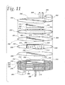
- FIG. 11 is a partially exploded perspective view of one embodiment of the assembly of FIG. 9 .
- FIG. 12 is a plan view of a heat exchanger plate of the assembly of FIG. 11 .
- FIG. 13 is a partial, exploded perspective view of a heat exchanger plate pair for use in one embodiment of the assembly of FIG. 9 .
- the anode and cathode flow streams exiting the fuel cell typically transfer heat to the incoming flows through a series of recuperative heat exchangers.
- this can include the process of transferring heat to a liquid water source in order to generate steam for steam reforming of a hydrocarbon fuel in order to generate the hydrogen-rich reformate flow.
- the cathode heat may be recuperatively transferred from the cathode exhaust flow stream to the incoming cathode air, while the anode heat is partially recuperatively transferred from the anode exhaust to the incoming humidified fuel, such as natural gas, which feeds the steam reformer, and partially transferred to the water to generate the water vapor being provided into the fuel to humidify the fuel.
- the water vapor within the anode exhaust may be recaptured to serve either wholly or in part as the water source for the steam reformer.
- the inventors discovered that a thermodynamic analysis of the system in which the anode (i.e., fuel side) exhaust stream is used to heat the humidified fuel and to evaporate the water reveals that there will be more energy available in the anode exhaust exiting the fuel cell than is required to be transferred to the incoming humidified fuel (i.e., water and fuel). However, a sizable portion of both the heat available in the anode exhaust and the heat required for the feed is in the form of latent heat.
- FIG. 1 shows the plot of temperature versus heat transferred for the anode exhaust and the water.
- the conditions in FIG. 1 assume a 400° C. anode exhaust temperature entering an evaporator (i.e., vaporizer) from a water-gas shift reactor, and a hypothetical counter flow evaporator capable of achieving full vaporization of the water, with minimal superheat.
- evaporator i.e., vaporizer
- the condensing of water vapor from the fully saturated anode exhaust and the isothermal vaporization of the water causes the temperature of the heat rejecting anode exhaust to drop below the temperature of the heat receiving water for a substantial portion of the heat duty (i.e., the water curve is located above the anode exhaust curve for Q values of about 1,100 to about 1750 W).
- the water curve is located above the anode exhaust curve for Q values of about 1,100 to about 1750 W.
- an additional heating source may be needed to evaporate sufficient water to satisfy the amount of steam required for methane reformation, which can be as high as 1.5 kW in a system with 6.5 kW electrical output. This additional heating source reduces system efficiency.
- the cathode (i.e., air side) exhaust may be used to evaporate water being provided into the fuel and/or to heat the fuel being provided into the system.
- the entire thermodynamic potential of the exhaust gases can be recaptured for preheating of the fuel cell feeds without mass transfer devices such as an enthalpy wheel, or additional heat sources.
- mass transfer devices such as an enthalpy wheel, or additional heat sources.
- the system where the cathode exhaust is used to vaporize water for humidifying the fuel and/or used to heat incoming fuel is also be capable of being passively controlled.
- the cathode exhaust is used to vaporize water for humidifying the fuel and/or used to heat incoming fuel, it may be desirable to utilize active control.
- FIGS. 2 and 3 illustrate a fuel cell system 1 according to a first preferred embodiment of the invention.
- the system 1 is a high temperature fuel cell stack system, such as a solid oxide fuel cell (SOFC) system or a molten carbonate fuel cell system.
- SOFC solid oxide fuel cell
- the system 1 may be a regenerative system, such as a solid oxide regenerative fuel cell (SORFC) system which operates in both fuel cell (i.e., discharge) and electrolysis (i.e., charge) modes or it may be a non-regenerative system which only operates in the fuel cell mode.
- SORFC solid oxide regenerative fuel cell
- the system 1 contains one or more high temperature fuel cell stacks 3 .
- the stack 3 may contain a plurality of SOFCs, SORFCs or molten carbonate fuel cells.
- Each fuel cell contains an electrolyte, an anode electrode on one side of the electrolyte in an anode chamber, a cathode electrode on the other side of the electrolyte in a cathode chamber, as well as other components, such as separator plates/electrical contacts, fuel cell housing and insulation.
- the oxidizer such as air or oxygen gas
- the fuel such as hydrogen or hydrocarbon fuel
- Any suitable fuel cell designs and component materials may be used.
- the system 1 also contains a heat transfer device 5 labeled as a fuel humidifier in FIG. 2 .
- the device 5 is adapted to transfer heat from a cathode exhaust of the fuel cell stack 3 to evaporate water to be provided to the fuel inlet stream and to also mix the fuel inlet stream with steam (i.e., the evaporated water).
- the heat transfer device 5 contains a water evaporator (i.e., vaporizer) 6 which is adapted to evaporate water using the heat from the cathode exhaust stream.
- the evaporator 6 contains a first input 7 operatively connected to a cathode exhaust outlet 9 of the fuel cell stack 3 , a second input 11 operatively connected to a water source 13 , and a first output 15 operatively connected to a fuel inlet 17 of the stack 3 .
- the heat transfer device 5 also contains a fuel—steam mixer 8 which mixes the steam or water vapor, provided into the mixer 8 from the first output 15 of the evaporator 6 through conduit 10 , and the input fuel, such as methane or natural gas, provided from a fuel inlet 19 , as shown in FIG. 3 .
- operatively connected means that components which are operatively connected may be directly or indirectly connected to each other.
- two components may be directly connected to each other by a fluid (i.e., gas and/or liquid) conduit.
- two components may be indirectly connected to each other such that a fluid stream passes between the first component to the second component through one or more additional components of the system.
- the system 1 also preferably contains a reformer 21 and a combustor 23 .
- the reformer 21 is adapted to reform a hydrocarbon fuel to a hydrogen containing reaction product and to provide the reaction product to the fuel cell stack 3 .
- the combustor 23 is preferably thermally integrated with the reformer 21 to provide heat to the reformer 21 .
- the fuel cell stack 3 cathode exhaust outlet 9 is preferably operatively connected to an inlet 25 of the combustor 23 .
- a hydrocarbon fuel source 27 is also operatively connected to the combustor 23 inlet 25 .
- the hydrocarbon fuel reformer 21 may be any suitable device which is capable of partially or wholly reforming a hydrocarbon fuel to form a carbon containing and free hydrogen containing fuel.
- the fuel reformer 21 may be any suitable device which can reform a hydrocarbon gas into a gas mixture of free hydrogen and a carbon containing gas.
- the fuel reformer 21 may reform a humidified biogas, such as natural gas, to form free hydrogen, carbon monoxide, carbon dioxide, water vapor and optionally a residual amount of unreformed biogas by a steam methane reformation (SMR) reaction.
- SMR steam methane reformation
- the fuel reformer 21 is thermally integrated with the fuel cell stack 3 to support the endothermic reaction in the reformer 21 and to cool the stack 3 .
- thermally integrated in this context means that the heat from the reaction in the fuel cell stack 3 drives the net endothermic fuel reformation in the fuel reformer 21 .
- the fuel reformer 21 may be thermally integrated with the fuel cell stack 3 by placing the reformer and stack in the same hot box 37 and/or in thermal contact with each other, or by providing a thermal conduit or thermally conductive material which connects the stack to the reformer.
- the combustor 23 provides a supplemental heat to the reformer 21 to carry out the SMR reaction during steady state operation.
- the combustor 23 may be any suitable burner which is thermally integrated with the reformer 21 .
- the combustor 23 receives the hydrocarbon fuel, such as natural gas, and an oxidizer (i.e., air or other oxygen containing gas), such as the stack 3 cathode exhaust stream, through inlet 25 .
- an oxidizer i.e., air or other oxygen containing gas
- the cathode exhaust stream may be provided into the combustor.
- the fuel and the cathode exhaust stream i.e., hot air
- the combustor outlet 26 is operatively connected to the inlet 7 of the heat transfer device 5 to provide the cathode exhaust mixed with the combusted fuel components from the combustor to the heat transfer device 5 . While the illustrated system 1 utilizes a cathode exhaust flow in the heat transfer device 5 that has passed through a combustor, it may be desirable in some systems to utilize a cathode exhaust flow in the heat transfer device 5 that has not been passed through a combustor.
- the supplemental heat to the reformer 21 is provided from both the combustor 23 which is operating during steady state operation of the reformer (and not just during start-up) and from the cathode (i.e., air) exhaust stream of the stack 3 .
- the combustor 23 is in direct contact with the reformer 21 , and the stack 3 cathode exhaust is configured such that the cathode exhaust stream contacts the reformer 21 and/or wraps around the reformer 21 to facilitate additional heat transfer. This lowers the combustion heat requirement for SMR.
- the reformer 21 is sandwiched between the combustor 23 and one or more stacks 3 to assist heat transfer.
- the combustor unit acts as a heat exchanger.
- the same combustor 23 may be used in both start-up and steady-state operation of the system 1 .
- the system 1 also includes a fuel preheater heat exchanger (i.e., anode recuperator) 29 which is adapted to heat the fuel inlet stream using heat from the fuel cell stack 3 anode exhaust stream exiting from the stack 3 anode exhaust outlet 31 .
- the system 1 further includes a cathode recuperator heat exchanger 33 which is adapted to heat an air inlet stream from an air blower 35 using heat from the cathode exhaust stream exiting the stack 3 cathode exhaust outlet 9 .
- the cathode exhaust stream mixed with the combusted fuel components from combustor 23 outlet 26 are provided into the cathode recuperator 33 to heat the air inlet stream.
- the cathode exhaust stream mixed with the combusted fuel components are then provided to the evaporator 6 of the heat transfer device 5 to evaporate the water to steam, which will then be provided into the fuel inlet stream heading into the reformer 21 .
- the fuel cell stack 3 , the reformer 21 , the combustor 23 , the fuel preheater heat exchanger 29 and the cathode recuperator heat exchanger 33 are located in a hot box 37 .
- the cathode recuperator heat exchanger 33 is intentionally undersized to ensure that the temperature of the cathode exhaust stream exiting the heat exchanger 33 is sufficiently high to allow the heat transfer device 5 to evaporate the water to steam via transfer of heat from the cathode exhaust stream.
- the cathode recuperator heat exchanger preferably has a size below a predetermined size, such that the cathode exhaust stream exits the cathode recuperator heat exchanger at a temperature of at least 200° C., such as 200° C. to 230° C., for example about 210° C.
- the cathode exhaust stream may enter the cathode recuperator heat exchanger 33 at a temperature of at least 800° C., such as about 800° C. to about 850° C., for example about 820° C.
- the cathode recuperator heat exchanger 33 is intentionally undersized to have an exchange rate of about 10 to 12 kW, such as about 11 kW for this highly preferred embodiment.
- a full sized heat exchanger for the highly preferred embodiment may have an exchange rate of about 16 kW. While specific temperatures and heat exchange rates have been described for one highly preferred embodiment, it should be understood that the exit and entrance temperatures and heat exchange rates will be highly dependent upon the particular parameters of each specific application, and accordingly, it should be understood that no limitations to specific exit and entrance temperatures or heat exchange rates are intended unless specifically recited in the claims.
- the system 1 also preferably contains an air preheater heat exchanger 39 which is adapted to preheat the air inlet stream from the air blower 35 using heat from an anode exhaust stream exiting from the stack anode outlet 31 .
- the air blower provides an air inlet stream into the system 1 which comprises at least 2.5 times, such as 2.5 to 6.5 times, preferably 3 to 4.5 times as much air as required for the fuel cell stack 3 to generate electricity.
- the blower 35 may preheat the air inlet stream to about 50° C.
- the slightly preheated inlet air stream is then provided from the blower into the air preheater heat exchanger 39 where it is preheated to about 100° C. to about 150° C., such as about 140° C., for example.
- This preheated air inlet stream then enters the cathode recuperator heat exchanger 33 at about 100° C. to about 150° C. and exits the heat exchanger 33 at about 700° C. to about 750° C., such as about 720° C. Since the preheated air inlet stream enters the cathode recuperator heat exchanger 33 at a temperature above room temperature, the cathode exhaust stream can exit the heat exchanger 33 at a temperature above 200° C. Thus, the air preheater heat exchanger 39 sufficiently preheats the air inlet stream to allow the use of an undersized cathode recuperator heat exchanger 33 , which reduces the overall system manufacturing cost.
- the air preheater 39 is located outside the hot box 37 and upstream of the cathode recuperator 33 , such that the air inlet stream is first heated by the anode exhaust stream in the air preheater 39 , followed by being heated by the cathode exhaust stream in the cathode recuperator 33 .
- the air inlet stream provided into the cathode inlet 41 of the stack 3 is heated by both the anode and cathode exhaust streams from the stack 3 .
- the system 1 optionally contains a water gas shift reactor 43 which is adapted to convert at least a portion of water vapor in the fuel cell stack anode exhaust stream into free hydrogen.
- the inlet 45 of the reactor 43 is operatively connected to the stack anode outlet 31
- the outlet 47 of the reactor 43 is operatively connected to an inlet 49 of the air preheater 39 .
- the water-gas shift reactor 43 may be any suitable device which converts at least a portion of the water exiting the fuel cell stack 3 fuel exhaust outlet 31 into free hydrogen.
- the reactor 43 may comprise a tube or conduit containing a catalyst which converts some or all of the carbon monoxide and water vapor in the anode exhaust stream into carbon dioxide and hydrogen.
- the catalyst may be any suitable catalyst, such as an iron oxide or a chromium promoted iron oxide catalyst.
- the system 1 also optionally contains a condenser 51 adapted to condense water vapor in the anode exhaust stream into liquid water, preferably using an ambient air flow as a heatsink.
- the system 1 also optionally contains a hydrogen recovery system 53 adapted to recover hydrogen from the anode exhaust stream after the anode exhaust stream passes through the condenser 51 .
- the hydrogen recovery system may be a pressure swing adsorption system or another suitable gas separation system, for example.
- the air preheater 39 partially condenses the water vapor in the anode exhaust stream prior to the anode exhaust stream entering the condenser 51 to reduce the load on the condenser 51 .
- the outlet 55 of the air preheater 39 is operatively connected to the inlet 57 of the condenser 51 .
- a first outlet 59 of the condenser 51 provides hydrogen and other gases separated from the water to the hydrogen recovery system 53 .
- a second outlet 61 of the condenser 51 provides water to an optional water purification system 63 .
- the water from the purification system 63 is provided to the evaporator 6 which comprises a portion of the heat transfer device 5 , through inlet 11 .
- the system 1 also optionally contains a desulfurizer 65 located in the path of the fuel inlet stream from the fuel source 27 .
- the desulfurizer 65 removes some or all of the sulfur from the fuel inlet stream.
- the desulfurizer 65 preferably comprises the catalyst, such as Co—Mo or other suitable catalysts, which produces CH.sub.4 and H.sub.2S gases from hydrogenated, sulfur containing natural gas fuel, and a sorbent bed, such as ZnO or other suitable materials, for removing the H.sub.2S gas from the fuel inlet stream.
- a sulfur free or reduced sulfur hydrocarbon fuel leaves the desulfurizer 65 .
- FIGS. 2 and 3 A method of operating the system 1 according to a first preferred embodiment of the present invention is described with reference to FIGS. 2 and 3 .
- the air inlet stream is provided from the air blower 35 into the air preheater 39 through conduit 101 .
- the air inlet stream is preheated in the air preheater 39 by exchanging heat with the anode exhaust stream coming from the water-gas shift reactor 43 .
- the preheated air inlet stream is then provided into the cathode recuperator 33 through conduit 103 , where the air inlet stream is heated to a higher temperature by exchanging heat with the cathode exhaust stream.
- the air inlet stream is then provided into the cathode inlet 41 of the stack 3 through conduit 105 .
- the air then exits the stack 3 cathode outlet 9 as the cathode exhaust stream.
- the cathode exhaust stream wraps around the reformer 21 and enters the combustion zone of the combustor 23 through conduit 107 and inlet 25 .
- Desulfurized natural gas or another hydrocarbon fuel is also supplied from the fuel inlet 27 through conduit 109 into the combustor 23 inlet 25 for additional heating.
- the exhaust stream from the combustor 23 i.e., cathode exhaust stream
- the cathode exhaust stream is then provided into the evaporator 6 of the heat transfer device 5 through conduit 113 .
- the rest of the heat left in the cathode exhaust stream is then extracted in the evaporator 6 for evaporating water for steam methane reformation before venting out through exhaust conduit 115 .
- the hydrocarbon fuel inlet stream enters the desulfurizer 65 from the fuel source 27 , such as a gas tank or a valved natural gas pipe.
- the desulfurized fuel inlet stream i.e., desulfurized natural gas
- the fuel mixer 8 the fuel is mixed with purified steam from the evaporator 6 .
- the steam/fuel mix is then provided into the fuel preheater 29 through conduit 119 .
- the steam/fuel mix is then heated by exchanging heat with the anode exhaust stream in the fuel preheater 29 before entering the reformer through conduit 121 .
- the reformate then enters the stack 3 anode inlet 17 from the reformer 21 through conduit 123 .
- the stack anode exhaust stream exists the anode outlet 31 and is provided into the fuel preheater 29 through conduit 125 , where it heats the incoming fuel/steam mix.
- the anode exhaust stream from the hot box 37 then enters the water gas shift reactor 43 through conduit 127 .
- the anode exhaust stream from reactor 43 is then provided into the air preheater 39 through conduit 129 , where it exchanges heat with the air inlet stream.
- the anode exhaust stream is then provided into the condenser 51 through conduit 131 , where water is removed from the anode exhaust stream and recycled or discharged.
- the water may be provided into the water purifier 63 through conduit 133 , from where it is provided into the evaporator through conduit 135 .
- water may be provided into the purifier 63 through a water inlet 137 , such as a water pipe.
- the hydrogen rich anode exhaust is then provided from the condenser 51 through conduit 139 into the hydrogen purification system 53 , where hydrogen is separated from the other gases in the stream.
- the other gases are purged through purge conduit 141 while hydrogen is provided for other uses or storage through conduit 143 .
- the fluid streams in the system 1 exchange heat in several different locations.
- the cathode exhaust stream is wrapped around the steam methane reformer 21 to supply the endothermic heat required for reformation.
- natural gas or other hydrocarbon fuel is added directly to the cathode exhaust stream passing through the combustor 23 as needed to satisfy the overall heat requirement for reformation.
- Heat from the high-temperature exhaust exiting the combustor 23 (containing the cathode exhaust stream and the combusted fuel components, referred to as “cathode exhaust stream”) is recuperated to the incoming cathode air (i.e., air inlet stream) in the cathode recuperator 33 .
- the heat from the anode exhaust stream exiting the anode side of the fuel cell stack 3 is first recuperated to the incoming anode feed (i.e., the fuel inlet stream) in the fuel preheater 29 and then recuperated to the incoming cathode feed (i.e., the air inlet stream) in the air preheater 39 .
- the air supplied to the fuel cell stack 3 from air blower 35 is provided in excess of the stoichiometric amount required for fuel cell reactions, in order to cool the stack and take away the heat produced by the stack.
- the typical ratio of air flow to stoichiometric amount is in excess of 4, such as 4.5 to 6, preferably about 5. This leads to substantially higher mass flow of cathode air than anode gas (i.e., fuel). Consequently, if the cathode exhaust stream only heats the air inlet stream, then the amount of heat which is transferred between the cathode exhaust and air inlet streams is significantly higher than that which is transferred between the anode exhaust and fuel inlet streams, typically by a factor of approximately 3.
- the system 1 transfers only a portion of the cathode exhaust stream heat to the incoming air inlet stream and uses the remainder of the available cathode exhaust stream heat for complete vaporization of the water in the evaporator 6 .
- the air inlet stream is heated to the appropriate fuel cell temperature, it is preheated by the anode exhaust stream in the air preheater 39 .
- This preheating ensures that the air inlet stream has a sufficiently high temperature when entering the cathode recuperator 33 to ensure that the recuperator 33 can raise the temperature of the air inlet stream to the appropriate fuel cell temperature
- FIGS. 4 and 5 show graphs of the fluid temperature vs. the heat transferred for the evaporator 6 (i.e., the water vaporizer), and the air preheater 39 , respectively, for one analyzed embodiment.
- the thermodynamic cross-over shown in FIG. 1 is eliminated. This removes the need for either a humidity exchanger or a supplemental heater which consumes additional fuel.
- the “temperature approach” is defined as the smallest temperature difference between the two fluid streams at any location in the heat exchanger.
- both of the heat exchangers i.e., the evaporator 6 and the air preheater 39
- both of the heat exchangers i.e., the evaporator 6 and the air preheater 39
- have a very small temperature approach located away from either end of the heat exchanger at the point where the two-phase region begins. It is advantageous to maximize the temperature approach in each heat exchanger, since the rate of heat transfer between the fluids will decrease as the local temperature difference between the streams decreases, leading to a need for a larger heat exchanger to transfer the required heat.
- the temperature approach will increase in the evaporator 6 . However, the temperature approach will decrease in the air preheater 39 . Conversely, if the portion of total cathode air preheat which occurs in the cathode recuperator 33 is increased, the temperature approach will increase in the air preheater 39 . However, the temperature approach will decrease in the evaporator 6 . Of the total cathode heat duty, there will then be some optimum percentage which should be transferred within the cathode recuperator 33 in order to maximize the temperature approach in both the evaporator 6 and the air preheater 39 .
- the inventors also discovered that by using the cathode exhaust stream for vaporizing the water, the amount of superheat in the steam exiting the evaporator 6 is very sensitive to the temperature and mass flow rate of the cathode exhaust stream entering the evaporator. This can be seen in FIG. 6 , which shows the impact of a 4.5% increase in cathode exhaust stream mass flow (with the cathode exhaust stream temperature into the evaporator remaining unchanged) on the resulting humidified natural gas temperature.
- the temperature of the humidified natural gas entering the fuel preheater 29 can be seen to increase by 28° C. due to this slight increase in cathode exhaust stream flow rate.
- This increase in temperature will result in a higher anode exhaust stream temperature exiting the fuel preheater, and subsequently a higher temperature exiting the water gas shift reactor 43 and entering the air preheater 39 .
- This in turn leads to an increase in the cathode air preheat, which will tend to increase the temperature of the cathode exhaust stream entering the evaporator 6 , thereby exacerbating the problem.
- the humidified natural gas temperature will continue to ratchet up, resulting in system stability problems, unless the inlet air flow rate is controlled.
- the cathode air (i.e., inlet air) flow rate needs to be controlled because it is one of the prime means of controlling the system 1 .
- the previously mentioned potential stability problems may be reduced or eliminated by having an adjustable cathode exhaust bypass around the evaporator 6 , through which a small portion of the cathode exhaust stream could be diverted in order to control the cathode exhaust flow rate through the evaporator 6 .
- This solution uses active control of the fluid flow rate.
- a passive approach is used to reduce or eliminate the previously mentioned potential stability problems without the need for additional monitoring and control.
- the inventors have discovered that a temperature of the humidified natural gas entering the fuel preheater 29 can be made to be relatively insensitive to changes in the cathode exhaust stream flow rate and/or temperature by limiting the potential for increased superheat in the evaporator through a temperature pinch.
- FIG. 7 illustrates the heat exchanger portion of the system of the third preferred embodiment.
- the other parts of the system of the third preferred embodiment are the same as those of the first preferred embodiment shown in FIGS. 2 and 3 .
- the direction of the water flow through the evaporator 6 is concurrent, rather than counter-current, with the flow of the cathode exhaust stream through the evaporator 6 .
- the temperature approach in the evaporator 6 located at the onset of the two-phase flow region, it is shifted to the end of the heat transfer region of the evaporator 6 , where the temperature approach will “pinch” to a value of zero or closely approaching zero. No heat transfer between the streams will occur after this point, and the two fluids will exit at or near a common temperature.
- the cathode exhaust stream flow rate may need to be increased slightly in order to ensure that the heat capacity in the cathode exhaust stream is sufficient to achieve full vapor quality in the water.
- the water i.e., steam
- the cathode exhaust stream exiting the evaporator 6 can then be used to preheat the fuel, such as natural gas in a second fuel preheater 67 . Since the fuel inlet stream has a very small flow rate compared to the cathode exhaust stream, it is quite easy to achieve 100% effective heat transfer and preheat the fuel inlet stream to the same temperature as the water vapor and cathode exhaust stream exiting the evaporator.
- the system of the third preferred embodiment also contains the second fuel preheater 67 .
- the fuel preheater 67 includes a first input 69 operatively connected to a cathode exhaust outlet 9 of the fuel cell stack 3 , a second input 71 operatively connected to the fuel source 27 , and a first output 73 operatively connected to the fuel inlet conduit 17 .
- the second fuel preheater 67 is adapted to transfer heat from the cathode exhaust stream of the fuel cell stack to the fuel inlet stream being provided to the fuel cell stack 3 .
- the evaporator 6 in the third preferred embodiment comprises a concurrent flow or “co-flow” evaporator in which the cathode exhaust stream and the water are adapted to flow in a same direction, and an output of the evaporator is operatively connected to an inlet of the fuel preheater 67 such that the cathode exhaust stream flows from the evaporator 6 into the second fuel preheater 67 .
- the water and the cathode exhaust stream are preferably provided into the same side of the evaporator and flow concurrent to each other.
- the water is converted to steam in the evaporator 6 and is provided into the steam/fuel mixer 8 .
- the cathode exhaust stream is provided from the evaporator into the second fuel preheater heat exchanger 67 where it heats the inlet fuel flow which is then provided through the mixer 8 and the first fuel preheater heat exchanger (anode recuperator 29 ) into the stack 3 .
- the system of the third preferred embodiment is substantially insensitive to variations in cathode exhaust stream temperature and mass flow.
- FIG. 8 shows that, for one analyzed embodiment, the humidified natural gas temperature entering the anode recuperator (i.e., first fuel preheater) 29 will increase by less than 7° C. due to a 6.8% increase in cathode exhaust stream mass flow in the system of the third preferred embodiment.
- Such a small temperature rise should not cause the temperature ratcheting described above, and therefore will result in system stability without the need for active control of the inlet air and/or cathode exhaust stream flow.
- water is evaporated using the heat from cathode exhaust stream.
- the air heat exchanger i.e., cathode recuperator
- the air heat exchanger is undersized so that the hot stream exits it at a high temperature of at least 200° C., such as 200° C. to 230° C.
- Air is fed into the system at a stoic of 2.5 and above to have enough exhaust heat for evaporating water needed for steam methane reformation.
- Preferably, between 2.5 and 6.5 times, more preferably between 3 and 4.5 times as much air is provided into the fuel cell stack as required for the fuel cell stack to generate electricity.
- the inlet air entering the cathode recuperator is preheated in the air preheater using the anode exhaust stream to reduce the load on the cathode recuperator.
- Water from the anode exhaust stream is partially condensed in the air pre-heater to reduce load in the anode condenser.
- the fuel humidifier 5 is preferably provided in the form of an integrated assembly 200 that includes, as a single integrated unit, the water evaporator 6 , a fuel heater or preheater, such as the fuel preheater 67 , and the fuel/steam mixer 8 connected to both the water evaporator 6 to receive steam therefrom and the fuel heater 67 to receive heated fuel therefrom.
- a fuel heater or preheater such as the fuel preheater 67
- the fuel/steam mixer 8 connected to both the water evaporator 6 to receive steam therefrom and the fuel heater 67 to receive heated fuel therefrom.
- the water evaporator 6 preferably includes a water flow path 202 in heat transfer relation with a heat carrying fluid flow path 204 , which in the illustrated system is a cathode exhaust gas flow path, while the fuel heater includes a fuel flow path 206 also in heat transfer relation with the heat carrying fluid flow path 204 , which again is the cathode exhaust gas flow path 204 for the illustrated system.
- the fuel/steam mixer 8 is connected to both the water flow path 202 to receive steam therefrom and to the fuel flow path 206 to receive heated fuel therefrom.
- the fuel preheater 67 is preferably located downstream from the water evaporator 6 with respect to the heat carrying fluid flow path 204 . However, in some applications, it may desirable for the fuel preheater 67 to be located upstream from the water evaporator 6 with respect to the heat carrying fluid flow path 204 .
- the water flow path 202 preferably includes a plurality of parallel water flow passages 210
- the fuel flow path 206 includes a plurality of parallel fuel flow passages 212
- the heat carrying fluid flow path 204 includes a plurality of parallel heat carrying fluid flow passages 214 interleaved with the water flow passages 210 in the water evaporator 6 and interleaved with the fuel flow passages 212 in the fuel heater 67 .
- the fuel/steam mixture 8 preferably is in the form of a manifold or plenum 216 that is connected to all of the water and fuel flow passages 210 and 212 .
- each of the water flow passages 210 include a liquid pressure drop inlet region 220 that provides a greater pressure drop than the remainder 222 of the water flow passage 210 to help ensure proper distribution of the water flow to all of the water flow passages 210 .
- regions 220 are preferred, in some applications it may be desirable for the water flow passages 210 to be free of any such regions 220 .
- each of the regions 220 be thermally isolated from the heat carrying fluid flow path 206 by a thermal break, shown schematically at 224 .
- the thermal break 224 acts to reduce conduction of heat to the pressure drop inlet regions 220 and preferably prevents or limits any vaporization of the water flow in the regions 220 .
- the water flow and the heat carrying fluid flows have a concurrent flow relationship through the integrated assembly 200 , the advantages of which were previously discussed herein and which include providing stability for the associated system because of the temperature pinch and making the system less sensitive to changes in the flow rate of the heat carrying fluid, as well as temperature changes in the heat carrying fluid.
- the concurrent flow arrangement is preferred, in some applications it may be desirable for the flow to be arranged so as to provide a counter-current relationship, which can possibly allow for a lower flow rate and/or inlet temperature for the heat carrying fluid flow in comparison to the concurrent flow relationship, or a higher humidified fuel outlet temperature.
- FIG. 11 shows one preferred embodiment of the integrated fuel humidifier assembly 200 .
- This embodiment utilizes a so-called stacked plate construction and includes a plurality of water/fuel plates or sheets 228 interleaved with a plurality of heat carrying fluid plates or frames 230 , with each of the water/fuel plates defining one of the water flow passages 210 and one of the fuel flow passages 212 , and each of the heat carrying fluid plates 230 defining one of the heat carrying fluid passages 214 .
- Each of the water/fuel plates 228 further includes a water/fuel mixing chamber 232 that is open to both of the passages 210 and 212 to receive steam and heated fuel, respectively, therefrom.
- Each of the heat carrying fluid plates 230 also includes a water/fuel mixing chamber 234 that is closed from the heat carrying fluid flow passage 214 . The chambers 232 and 234 are aligned to form the water/fuel mixing plenum 216 that extends through all of the plates 228 and 230 .
- Each of the water/fuel plates 228 further includes a pair of heat carrying fluid bypass openings 238 and 240 that are closed to the passages 210 and 212 in the water/fuel plate 228 .
- the openings 238 and 240 in each of the plates 228 are aligned with the opposite ends, respectively, of the heat carrying fluid flow passages 214 in the heat carrying fluid plates 230 to form a heat carrying fluid inlet manifold 242 and a heat carrying fluid exit manifold 244 , respectively, that extend through all of the plates 228 and 230 to direct the heat carrying fluid into and out of, respectively, the passages 214 .
- Each of the water/fuel plates 228 also includes a water inlet opening 246 , with the openings 246 being aligned with each other and a water bypass opening 250 in each of the heat carrying fluid plates 230 to form a water inlet manifold 252 that extends through all of the plates 228 and 230 .
- Each of the heat carrying fluid plates includes a fuel bypass opening 254 , with the openings 254 aligned with an end of the fuel flow passage 212 in each of the water/fuel plates 228 opposite from the chamber 232 to form a fuel inlet plenum or manifold 256 that extends through all of the plates 228 and 230 to supply fuel to each of the passages 212 .
- the assembly 200 also includes separator sheets 260 that are interleaved between each of the plates 228 and 230 in order to seal their respective flow passages from each other, as is known in stacked plate heat exchanger constructions.
- Each of the separator sheets 260 has openings 262 , 264 , 268 , 270 and 272 that are aligned with and correspond to the chambers 232 and 234 , the bypass openings 238 , the bypass openings 240 , the water inlet openings 246 and bypass openings 250 , and the fuel bypass openings 254 , respectively.
- the assembly 200 also includes a pair of end plates 280 and 282 that sandwich the plates 228 and 230 and sheets 260 to seal the assembly 200 in a fluid tight manner.
- the end plate 280 includes a heat carrying fluid inlet connection or port 284 that is aligned with the heat carrying fluid inlet manifold 242 to direct heat carrying fluid thereto, and a humidified fuel outlet connection or port 286 that is aligned with the water/fuel mixing plenum 236 at an end of the plenum 236 opposite from the openings to the passages 210 and 212 to direct humidified fuel from aligned with the fuel manifold 256 to supply the fuel flow thereto, and a heat carrying fluid outlet connection or port 292 that is aligned with the outlet manifold 244 to direct heat carrying fluid therefrom.
- the passage 210 is defined by a continuous slot that extends from the water inlet opening 246 to the water/fuel mixing chamber 232 , with the slot being open to both faces of the plate 228 .
- the fuel passages 212 is defined by a continuous slot that extends from the fuel inlet manifold 256 to the water/fuel mixing chamber 232 , again with the slot being open to the opposing faces of the water/fuel plate 228 .
- the pressure reduction region 220 of the passage 210 is defined by a portion of the slot that is formed in a tight serpentine pattern with a relatively narrow slot width, which together provide a tortuous flow path.
- the water passage 210 then continues to a more open region of the slot where vaporization of the water occurs.
- the initial length of the slot adjacent the pressure reduction region 220 has a reduced width in order to avoid separation of the water flow as it moves from the pressure reduction region 220 to the remainder 222 of the flow passage 210 , with the passage 210 widening further as it extends to the chamber 232 .
- each of the water/fuel plates 228 also includes the thermal break 224 in the form of a slit or slot 300 that extends for the length of the pressure drop inlet region 220 between the pressure reduction region 220 and the remainder 222 of the water flow passage 210 . As seen in FIG. 12 , each of the water/fuel plates 228 also includes the thermal break 224 in the form of a slit or slot 300 that extends for the length of the pressure drop inlet region 220 between the pressure reduction region 220 and the remainder 222 of the water flow passage 210 . As seen in FIG.
- each of the heat carrying fluid plates 230 includes a corresponding slit or slot 302
- each of the separator sheets 260 includes a corresponding slit or slot 304
- each of the end plates 282 includes a corresponding slit or slot 306 , with all of the slits 300 , 302 , 304 , 306 being aligned throughout the stack to form a plenum 308 that extends through the stack and is open to atmosphere.
- the thermal break 224 acts to minimize conduction of heat to the pressure drop inlet region 220 and preferably prevents or limits any vaporization of the water flow in the pressure reduction region 220 to ensure that the water flow remains in the liquid phase in the pressure reduction region 220 .
- thermal break 224 is preferred, in some applications it may be desirable not to have the thermal break 224 in the assembly 200 .
- the flow passage 210 directs the water flow in a globally concurrent flow relationship with the heat carrying fluid flow in the passage 214 , but is formed with a serpentine configuration so as to provide localized cross flow with respect to the heat carrying fluid flow in the passage 214 , thereby improving the transfer of heat to the water while still providing the desired concurrent flow relationship.
- each of the flow passages 214 includes extended surfaces, which in the illustrated embodiment are shown in the form of a fin or turbulator insert 310 , many suitable types of which are known. Extended surfaces may also be provided in the flow passages 210 and 212 , but are not shown in the illustrated embodiment.
- a water/fuel plate pair 312 is shown to illustrate one alternate embodiment for forming the water flow passage 210 .
- Each plate 314 , 316 of the plate pair 312 includes a plurality of discrete slots 318 that are arranged so as to overlie portions of corresponding discrete slots 318 in the opposite plate to form the water flow passage 210 , with the water flowing from one of the slots 318 in one of the plates 314 , 316 to a corresponding slot 318 in the opposite plate 314 , 316 and then from that corresponding slot 318 back to a second corresponding slot 318 in the first plate 314 , 316 and so forth until the water flows into the water/fuel mixer 8 .
- the pressure reduction region 220 in this embodiment is defined by multiple ones of the slots 318 , each of a relatively narrow width and short length, thereby requiring multiple changes in flow direction and providing the tortuous flow path.
- the water flow passage 210 is divided into three parallel legs 320 , but it should be understood that such a configuration is optional and will be highly dependent upon the requirements of each application. It should also be appreciated that a plurality of the plate pairs 312 of appropriate shape and size could be substituted for the water/fuel plates 228 in the embodiment shown in FIGS. 11 and 12 .
- any suitable heat exchanger construction can be utilized to form the assembly 200 , including, for example, plate and bar type constructions, drawn cup constructions, nested plate constructions, and constructions that incorporate discrete heat transfer tubes. It should also be appreciated that the particular type of heat exchanger construction employed will be highly dependent upon the particular requirements of the system in which the integrated humidifier assembly 200 is employed. In this regard, it should be understood that while the integrated fuel humidifier assembly 200 has been described herein in connection with the fuel cell system 1 , the integrated fuel humidifier assembly may find use in many other types of systems, and that no limitation to a fuel cell system is intended unless expressly recited in the claims.
- the integrated assembly 200 may be made utilizing any suitable material for the particular application, when employed in the fuel cell system 1 it is preferred that the sheets 260 and plates 228 , 230 , 280 , and 282 be formed from stainless steel or another suitable corrosion-resistant alloy and be nickel-brazed or brazed using another suitable corrosion-resistant brazing alloy.
Abstract
Description
Claims (5)
Priority Applications (1)
| Application Number | Priority Date | Filing Date | Title |
|---|---|---|---|
| US14/196,342 US9413017B2 (en) | 2005-05-09 | 2014-03-04 | High temperature fuel cell system with integrated heat exchanger network |
Applications Claiming Priority (2)
| Application Number | Priority Date | Filing Date | Title |
|---|---|---|---|
| US11/124,810 US8691462B2 (en) | 2005-05-09 | 2005-05-09 | High temperature fuel cell system with integrated heat exchanger network |
| US14/196,342 US9413017B2 (en) | 2005-05-09 | 2014-03-04 | High temperature fuel cell system with integrated heat exchanger network |
Related Parent Applications (1)
| Application Number | Title | Priority Date | Filing Date |
|---|---|---|---|
| US11/124,810 Continuation US8691462B2 (en) | 2005-05-09 | 2005-05-09 | High temperature fuel cell system with integrated heat exchanger network |
Publications (2)
| Publication Number | Publication Date |
|---|---|
| US20140186729A1 US20140186729A1 (en) | 2014-07-03 |
| US9413017B2 true US9413017B2 (en) | 2016-08-09 |
Family
ID=37311275
Family Applications (2)
| Application Number | Title | Priority Date | Filing Date |
|---|---|---|---|
| US11/124,810 Active 2033-04-10 US8691462B2 (en) | 2005-05-09 | 2005-05-09 | High temperature fuel cell system with integrated heat exchanger network |
| US14/196,342 Active 2025-08-02 US9413017B2 (en) | 2005-05-09 | 2014-03-04 | High temperature fuel cell system with integrated heat exchanger network |
Family Applications Before (1)
| Application Number | Title | Priority Date | Filing Date |
|---|---|---|---|
| US11/124,810 Active 2033-04-10 US8691462B2 (en) | 2005-05-09 | 2005-05-09 | High temperature fuel cell system with integrated heat exchanger network |
Country Status (7)
| Country | Link |
|---|---|
| US (2) | US8691462B2 (en) |
| JP (1) | JP2006318909A (en) |
| CN (1) | CN1862862B (en) |
| AU (1) | AU2006201422A1 (en) |
| BR (1) | BRPI0601629A (en) |
| DE (1) | DE102006020405B4 (en) |
| FR (1) | FR2894719B1 (en) |
Cited By (10)
| Publication number | Priority date | Publication date | Assignee | Title |
|---|---|---|---|---|
| US10892507B2 (en) | 2014-01-31 | 2021-01-12 | Fuelcell Energy, Inc. | Reformer-electrolyzer-purifier (REP) assembly for hydrogen production, systems incorporating same and method of producing hydrogen |
| US10897055B2 (en) | 2017-11-16 | 2021-01-19 | Fuelcell Energy, Inc. | Load following power generation and power storage using REP and PEM technology |
| US11043684B2 (en) | 2015-11-17 | 2021-06-22 | Fuelcell Energy, Inc. | Fuel cell system having enhanced CO2 capture |
| US11201337B2 (en) | 2018-12-21 | 2021-12-14 | Fuelcell Energy, Inc. | System and method for removing water and hydrogen from anode exhaust |
| US11264625B2 (en) | 2018-09-12 | 2022-03-01 | Fuelcell Energy, Inc. | Two-phase water cooling in an electrochemical hydrogen separator |
| US11309563B2 (en) | 2016-04-21 | 2022-04-19 | Fuelcell Energy, Inc. | High efficiency fuel cell system with hydrogen and syngas export |
| US11339333B2 (en) | 2016-04-21 | 2022-05-24 | Fuelcell Energy, Inc. | Fluidized catalytic cracking unit system with integrated reformer-electrolyzer-purifier |
| US11495806B2 (en) | 2019-02-04 | 2022-11-08 | Fuelcell Energy, Inc. | Ultra high efficiency fuel cell power generation system |
| US11541350B2 (en) | 2018-08-14 | 2023-01-03 | Fuelcell Energy, Inc. | Heat recovery from an electrochemical hydrogen separation system |
| US11710836B2 (en) | 2017-11-22 | 2023-07-25 | Fuelcell Energy, Inc. | Hydrogen generation using a fuel cell system with an REP |
Families Citing this family (43)
| Publication number | Priority date | Publication date | Assignee | Title |
|---|---|---|---|---|
| US20060251934A1 (en) * | 2005-05-09 | 2006-11-09 | Ion America Corporation | High temperature fuel cell system with integrated heat exchanger network |
| US20060248799A1 (en) * | 2005-05-09 | 2006-11-09 | Bandhauer Todd M | High temperature fuel cell system with integrated heat exchanger network |
| US8691462B2 (en) | 2005-05-09 | 2014-04-08 | Modine Manufacturing Company | High temperature fuel cell system with integrated heat exchanger network |
| US7858256B2 (en) | 2005-05-09 | 2010-12-28 | Bloom Energy Corporation | High temperature fuel cell system with integrated heat exchanger network |
| US7998632B2 (en) * | 2005-05-20 | 2011-08-16 | Delphi Technologies, Inc. | Anode tail gas recycle cooler and re-heater for a solid oxide fuel cell stack assembly |
| US7233079B1 (en) | 2005-10-18 | 2007-06-19 | Willard Cooper | Renewable energy electric power generating system |
| JP2007165118A (en) * | 2005-12-14 | 2007-06-28 | Ebara Ballard Corp | Fuel cell unit and preheating unit |
| US7659022B2 (en) | 2006-08-14 | 2010-02-09 | Modine Manufacturing Company | Integrated solid oxide fuel cell and fuel processor |
| EP1982364A4 (en) | 2006-01-23 | 2010-07-07 | Bloom Energy Corp | Modular fuel cell system |
| US8241801B2 (en) | 2006-08-14 | 2012-08-14 | Modine Manufacturing Company | Integrated solid oxide fuel cell and fuel processor |
| WO2008051368A2 (en) * | 2006-10-23 | 2008-05-02 | Bloom Energy Corporation | Dual function heat exchanger for start-up humidification and facility heating in sofc system |
| JP4914273B2 (en) * | 2007-04-02 | 2012-04-11 | 日本電信電話株式会社 | Hydrogen production method and hydrogen production system |
| US8920997B2 (en) | 2007-07-26 | 2014-12-30 | Bloom Energy Corporation | Hybrid fuel heat exchanger—pre-reformer in SOFC systems |
| US8852820B2 (en) | 2007-08-15 | 2014-10-07 | Bloom Energy Corporation | Fuel cell stack module shell with integrated heat exchanger |
| DE102008005839A1 (en) * | 2008-01-24 | 2009-07-30 | Borit Leichtbau-Technik Gmbh | Method for thermally integrating a fuel cell system, comprises utilizing exhaust gases of the fuel cells in a construction unit made of heat transmission plates by using a system from inlet openings and outlet openings formed in the plate |
| US8288041B2 (en) * | 2008-02-19 | 2012-10-16 | Bloom Energy Corporation | Fuel cell system containing anode tail gas oxidizer and hybrid heat exchanger/reformer |
| US8968958B2 (en) | 2008-07-08 | 2015-03-03 | Bloom Energy Corporation | Voltage lead jumper connected fuel cell columns |
| FI120949B (en) * | 2008-07-10 | 2010-05-14 | Waertsilae Finland Oy | Method and arrangement for enhancing the preheating of the fuel cell system |
| KR100987823B1 (en) | 2009-01-12 | 2010-10-18 | 한국과학기술원 | Solid Oxide Fuel Cell System |
| KR100992340B1 (en) * | 2009-01-12 | 2010-11-04 | 두산중공업 주식회사 | Integrated Vaporizer and Superheater for Fuel Cell |
| KR100987824B1 (en) | 2009-01-12 | 2010-10-18 | 한국과학기술원 | Start-up protocol of Self-sustained Solid Oxide Fuel Cell System |
| DE102009009675A1 (en) * | 2009-02-19 | 2010-08-26 | Daimler Ag | Fuel cell system with at least one fuel cell |
| CN102782297B (en) * | 2010-01-13 | 2016-03-02 | 克利尔赛恩燃烧公司 | For strengthen and reduce heat trnasfer device and for irritation fever transmission and protection temperature sensitivity surface method |
| US8440362B2 (en) | 2010-09-24 | 2013-05-14 | Bloom Energy Corporation | Fuel cell mechanical components |
| WO2012094514A1 (en) | 2011-01-06 | 2012-07-12 | Bloom Energy Corporation | Sofc hot box components |
| JP5675490B2 (en) | 2011-05-13 | 2015-02-25 | 本田技研工業株式会社 | Fuel cell module |
| JP5653834B2 (en) * | 2011-05-13 | 2015-01-14 | 本田技研工業株式会社 | Fuel cell system |
| JP5828690B2 (en) * | 2011-07-05 | 2015-12-09 | 日本特殊陶業株式会社 | Fuel cell material supply device, fuel cell system |
| GB2494667A (en) * | 2011-09-15 | 2013-03-20 | Rolls Royce Fuel Cell Systems Ltd | A solid oxide fuel cell system |
| GB2494666B (en) * | 2011-09-15 | 2014-11-05 | Rolls Royce Fuel Cell Systems Ltd | A solid oxide fuel cell system |
| KR101363365B1 (en) | 2012-06-04 | 2014-02-17 | 주식회사 경동나비엔 | Fuel cell system |
| WO2014085696A1 (en) * | 2012-11-27 | 2014-06-05 | Clearsign Combustion Corporation | Precombustion ionization |
| DE102012222105A1 (en) * | 2012-12-03 | 2014-06-05 | Bayerische Motoren Werke Aktiengesellschaft | Fuel cell assembly and method of operating the fuel cell assembly |
| US9755263B2 (en) | 2013-03-15 | 2017-09-05 | Bloom Energy Corporation | Fuel cell mechanical components |
| JP6122360B2 (en) * | 2013-07-19 | 2017-04-26 | 本田技研工業株式会社 | Fuel cell module |
| WO2015061274A1 (en) | 2013-10-23 | 2015-04-30 | Bloom Energy Corporation | Pre-reformer for selective reformation of higher hydrocarbons |
| EP3105810B1 (en) | 2014-02-12 | 2022-08-17 | Bloom Energy Corporation | Structure and method for fuel cell system where multiple fuel cells and power electronics feed loads in parallel allowing for integrated electrochemical impedance spectroscopy ("eis") |
| US10651496B2 (en) | 2015-03-06 | 2020-05-12 | Bloom Energy Corporation | Modular pad for a fuel cell system |
| WO2017217434A1 (en) * | 2016-06-16 | 2017-12-21 | 京セラ株式会社 | Reformer, cell stack device, fuel cell module and fuel cell device |
| JP7016024B2 (en) * | 2016-11-29 | 2022-02-04 | パナソニックIpマネジメント株式会社 | High temperature operation type fuel cell system |
| EP3386017B1 (en) * | 2017-04-07 | 2019-11-20 | Panasonic Intellectual Property Management Co., Ltd. | High-temperature operating fuel cell system |
| US11398634B2 (en) | 2018-03-27 | 2022-07-26 | Bloom Energy Corporation | Solid oxide fuel cell system and method of operating the same using peak shaving gas |
| WO2023163182A1 (en) * | 2022-02-28 | 2023-08-31 | 株式会社アイシン | Fuel cell system |
Citations (92)
| Publication number | Priority date | Publication date | Assignee | Title |
|---|---|---|---|---|
| US3488266A (en) | 1967-12-12 | 1970-01-06 | Continental Oil Co | Electrochemical reduction of benzene using a carbon anode |
| US4041210A (en) | 1976-08-30 | 1977-08-09 | United Technologies Corporation | Pressurized high temperature fuel cell power plant with bottoming cycle |
| US4182795A (en) | 1978-07-10 | 1980-01-08 | Energy Research Corporation | Fuel cell thermal control and reforming of process gas hydrocarbons |
| US4532192A (en) | 1984-11-06 | 1985-07-30 | Energy Research Corporation | Fuel cell system |
| US4622275A (en) | 1984-07-31 | 1986-11-11 | Hitachi, Ltd. | Fuel cell power plant |
| US4792502A (en) | 1986-11-14 | 1988-12-20 | International Fuel Cells Corporation | Apparatus for producing nitrogen |
| US4898792A (en) | 1988-12-07 | 1990-02-06 | Westinghouse Electric Corp. | Electrochemical generator apparatus containing modified high temperature insulation and coated surfaces for use with hydrocarbon fuels |
| US4917971A (en) | 1989-03-03 | 1990-04-17 | Energy Research Corporation | Internal reforming fuel cell system requiring no recirculated cooling and providing a high fuel process gas utilization |
| US4983471A (en) | 1989-12-28 | 1991-01-08 | Westinghouse Electric Corp. | Electrochemical cell apparatus having axially distributed entry of a fuel-spent fuel mixture transverse to the cell lengths |
| US5034287A (en) | 1990-04-23 | 1991-07-23 | International Fuel Cells Corporation | Fuel cell cooling using heat of reaction |
| US5047299A (en) | 1990-07-25 | 1991-09-10 | Westinghouse Electric Corp. | Electrochemical cell apparatus having an integrated reformer-mixer nozzle-mixer diffuser |
| US5079105A (en) | 1989-05-18 | 1992-01-07 | Asea Brown Boveri Ltd. | Device for conversion of chemical energy from hydrocarbons into electric energy by an electrochemical high-temperature process |
| EP0467051A1 (en) | 1990-05-30 | 1992-01-22 | Ishikawajima-Harima Heavy Industries Co., Ltd. | LNG cryogenic power generation system using molten carbonate fuel cells |
| US5084362A (en) | 1990-08-29 | 1992-01-28 | Energy Research Corporation | Internal reforming molten carbonate fuel cell system with methane feed |
| US5094926A (en) | 1989-01-09 | 1992-03-10 | Ishikawajima-Harima Heavy Industries Co., Ltd. | Electric power producing system using molten carbonate type fuel cell |
| US5143800A (en) | 1990-07-25 | 1992-09-01 | Westinghouse Electric Corp. | Electrochemical cell apparatus having combusted exhaust gas heat exchange and valving to control the reformable feed fuel composition |
| US5170124A (en) | 1990-06-08 | 1992-12-08 | Minister Of National Defence Of Her Majesty's Canadian Government | Method and apparatus for monitoring fuel cell performance |
| US5169730A (en) | 1990-07-25 | 1992-12-08 | Westinghouse Electric Corp. | Electrochemical cell apparatus having an exterior fuel mixer nozzle |
| US5302470A (en) | 1989-05-16 | 1994-04-12 | Osaka Gas Co., Ltd. | Fuel cell power generation system |
| US5366819A (en) | 1993-10-06 | 1994-11-22 | Ceramatec, Inc. | Thermally integrated reformer for solid oxide fuel cells |
| US5441821A (en) | 1994-12-23 | 1995-08-15 | Ballard Power Systems Inc. | Electrochemical fuel cell system with a regulated vacuum ejector for recirculation of the fluid fuel stream |
| US5498487A (en) | 1994-08-11 | 1996-03-12 | Westinghouse Electric Corporation | Oxygen sensor for monitoring gas mixtures containing hydrocarbons |
| US5501914A (en) | 1993-09-01 | 1996-03-26 | Mitsubishi Jukogyo Kabushiki Kaisha | Solid oxide electrolyte fuel cell |
| US5505824A (en) | 1995-01-06 | 1996-04-09 | United Technologies Corporation | Propellant generator and method of generating propellants |
| US5527631A (en) | 1994-02-18 | 1996-06-18 | Westinghouse Electric Corporation | Hydrocarbon reforming catalyst material and configuration of the same |
| US5573867A (en) | 1996-01-31 | 1996-11-12 | Westinghouse Electric Corporation | Purge gas protected transportable pressurized fuel cell modules and their operation in a power plant |
| US5601937A (en) | 1995-01-25 | 1997-02-11 | Westinghouse Electric Corporation | Hydrocarbon reformer for electrochemical cells |
| US5686196A (en) | 1996-10-09 | 1997-11-11 | Westinghouse Electric Corporation | System for operating solid oxide fuel cell generator on diesel fuel |
| US5733675A (en) | 1995-08-23 | 1998-03-31 | Westinghouse Electric Corporation | Electrochemical fuel cell generator having an internal and leak tight hydrocarbon fuel reformer |
| US5741605A (en) | 1996-03-08 | 1998-04-21 | Westinghouse Electric Corporation | Solid oxide fuel cell generator with removable modular fuel cell stack configurations |
| CN1180096A (en) | 1997-11-07 | 1998-04-29 | 张炳魁 | Metallurgical waste ash content controlled formed coke and molding coal and its producing method |
| US5763114A (en) | 1994-09-01 | 1998-06-09 | Gas Research Institute | Integrated reformer/CPN SOFC stack module design |
| US5914200A (en) | 1993-06-14 | 1999-06-22 | Siemens Aktiengesellschaft | High-temperature fuel cell stack arrangement with centrally located exit air space |
| US5955039A (en) | 1996-12-19 | 1999-09-21 | Siemens Westinghouse Power Corporation | Coal gasification and hydrogen production system and method |
| US6013385A (en) | 1997-07-25 | 2000-01-11 | Emprise Corporation | Fuel cell gas management system |
| US6051125A (en) | 1998-09-21 | 2000-04-18 | The Regents Of The University Of California | Natural gas-assisted steam electrolyzer |
| US6066408A (en) | 1997-08-07 | 2000-05-23 | Plug Power Inc. | Fuel cell cooler-humidifier plate |
| US6124050A (en) | 1996-05-07 | 2000-09-26 | Siemens Aktiengesellschaft | Process for operating a high temperature fuel cell installation, and high temperature fuel cell installation |
| US20010014414A1 (en) * | 2000-02-16 | 2001-08-16 | Nissan Motor Co., Ltd. | Fuel cell system and method of controlling the same |
| US6280865B1 (en) | 1999-09-24 | 2001-08-28 | Plug Power Inc. | Fuel cell system with hydrogen purification subsystem |
| US6329090B1 (en) | 1999-09-03 | 2001-12-11 | Plug Power Llc | Enthalpy recovery fuel cell system |
| US6348278B1 (en) | 1998-06-09 | 2002-02-19 | Mobil Oil Corporation | Method and system for supplying hydrogen for use in fuel cells |
| US20020025463A1 (en) | 2000-07-05 | 2002-02-28 | Monika Derflinger | Fuel cell system |
| US20020028362A1 (en) | 2000-09-01 | 2002-03-07 | Dennis Prediger | Anode oxidation protection in a high-temperature fuel cell |
| US6383671B1 (en) | 1998-09-08 | 2002-05-07 | Lynntech, Inc. | Gas humidification device for operation testing and evaluation of fuel cells |
| US6403245B1 (en) | 1999-05-21 | 2002-06-11 | Microcoating Technologies, Inc. | Materials and processes for providing fuel cells and active membranes |
| US20020114988A1 (en) * | 2001-02-21 | 2002-08-22 | Nissan Motor Co., Ltd. | Fuel cell system |
| US6451466B1 (en) | 2000-04-06 | 2002-09-17 | Utc Fuel Cells, Llc | Functional integration of multiple components for a fuel cell power plant |
| CN1377097A (en) | 2002-04-16 | 2002-10-30 | 上海交通大学 | Combined electric generator system integrating fuel battery of carbonate with turbine |
| US6514634B1 (en) | 2000-09-29 | 2003-02-04 | Plug Power Inc. | Method and system for humidification of a fuel |
| US6531243B2 (en) | 1998-09-14 | 2003-03-11 | Forschungszentrum Jülich GmbH | Solid oxide fuel operating with an excess of fuel |
| US20030162067A1 (en) | 2002-02-20 | 2003-08-28 | Ion America Corporation | Fuel water vapor replenishment system for a fuel cell |
| US6623880B1 (en) | 2001-05-29 | 2003-09-23 | The United States Of America As Represented By The Department Of Energy | Fuel cell-fuel cell hybrid system |
| US6630264B2 (en) | 2000-05-01 | 2003-10-07 | Delphi Technologies, Inc. | Solid oxide fuel cell process gas sampling for analysis |
| US20030196893A1 (en) | 2002-04-23 | 2003-10-23 | Mcelroy James Frederick | High-temperature low-hydration ion exchange membrane electrochemical cell |
| US20040013913A1 (en) | 2002-07-16 | 2004-01-22 | Siemens Westinghouse Power Corporation | Method and system for controlling the operating temperature of a fuel cell |
| WO2004013258A1 (en) | 2002-08-02 | 2004-02-12 | Catacel Corporation | Autothermal catalytic stem reformer |
| JP2004071312A (en) | 2002-08-05 | 2004-03-04 | Tokyo Gas Co Ltd | Heat self supporting solid oxide fuel cell system |
| WO2004021497A2 (en) | 2002-08-07 | 2004-03-11 | Battelle Memorial Institute | Passive vapor exchange systems and techniques for fuel reforming and prevention of carbon fouling |
| US6713040B2 (en) | 2001-03-23 | 2004-03-30 | Argonne National Laboratory | Method for generating hydrogen for fuel cells |
| WO2004027912A2 (en) | 2002-09-23 | 2004-04-01 | Hydrogenics Corporation | A fuel cell system and method of operating the same |
| US20040089438A1 (en) | 2002-11-08 | 2004-05-13 | Modine Manufacturing Co., | Heat exchanger |
| US6749958B2 (en) | 2000-07-10 | 2004-06-15 | Global Thermmelectric Inc. | Integrated module for solid oxide fuel cell systems |
| US6759155B2 (en) | 2000-05-01 | 2004-07-06 | Delphi Technologies, Inc. | Plate construction of high temperature air-to-air heat exchanger |
| US6779351B2 (en) | 2000-09-27 | 2004-08-24 | Idalex Technologies, Inc. | Fuel cell systems with evaporative cooling and methods for humidifying and adjusting the temperature of the reactant streams |
| WO2004093214A2 (en) | 2003-04-09 | 2004-10-28 | Ion America Corporation | Co-production of hydrogen and electricity in a high temperature electrochemical system |
| US6811913B2 (en) | 2000-11-15 | 2004-11-02 | Technology Management, Inc. | Multipurpose reversible electrochemical system |
| US6821663B2 (en) | 2002-10-23 | 2004-11-23 | Ion America Corporation | Solid oxide regenerative fuel cell |
| US6854688B2 (en) | 2002-05-03 | 2005-02-15 | Ion America Corporation | Solid oxide regenerative fuel cell for airplane power generation and storage |
| US6861169B2 (en) | 2001-05-09 | 2005-03-01 | Nuvera Fuel Cells, Inc. | Cogeneration of power and heat by an integrated fuel cell power system |
| US20050048338A1 (en) | 2003-08-25 | 2005-03-03 | Matsushita Electric Industrial Co., Ltd. | Polymer electrolyte fuel cell system and operation method thereof |
| US6878474B2 (en) | 2000-01-03 | 2005-04-12 | Idatech, Llc | System and method for recovering thermal energy from a fuel processing system |
| US6924053B2 (en) | 2003-03-24 | 2005-08-02 | Ion America Corporation | Solid oxide regenerative fuel cell with selective anode tail gas circulation |
| US20050221137A1 (en) | 2004-03-31 | 2005-10-06 | Todd Bandhauer | Fuel humidifier and pre-heater for use in a fuel cell system |
| US7045238B2 (en) | 2003-03-24 | 2006-05-16 | Ion America Corporation | SORFC power and oxygen generation method and system |
| US7060382B2 (en) | 2003-05-15 | 2006-06-13 | Fuelcell Energy, Inc. | Fuel cell system with recycle of anode exhaust gas |
| US7063047B2 (en) | 2003-09-16 | 2006-06-20 | Modine Manufacturing Company | Fuel vaporizer for a reformer type fuel cell system |
| US20060147771A1 (en) | 2005-01-04 | 2006-07-06 | Ion America Corporation | Fuel cell system with independent reformer temperature control |
| US7087331B2 (en) | 2000-10-30 | 2006-08-08 | Questair Technologies Inc. | Energy efficient gas separation for fuel cells |
| JP2006302260A (en) | 2005-03-11 | 2006-11-02 | Infineon Technologies Ag | Safe and quick calculation unit |
| US7132230B2 (en) | 2002-06-28 | 2006-11-07 | Fujikin Incorporated | Cytotoxic assay and new established cell line of sturgeon origin |
| US20060251939A1 (en) | 2005-05-09 | 2006-11-09 | Bandhauer Todd M | High temperature fuel cell system with integrated heat exchanger network |
| DE102006020145A1 (en) | 2005-05-09 | 2006-11-16 | Modine Manufacturing Co., Racine | Fuel cell system with integrated fuel humidifier unit |
| DE102006020097A1 (en) | 2005-05-09 | 2006-11-16 | Modine Manufacturing Co., Racine | Fuel cell system and method of operation |
| WO2006121992A2 (en) | 2005-05-09 | 2006-11-16 | Ion America Corporation | High temperature fuel cell system with integrated heat exchanger network |
| US7255804B2 (en) | 2002-02-15 | 2007-08-14 | University Of Delaware | Process for making photonic crystal circuits using an electron beam and ultraviolet lithography combination |
| US7285350B2 (en) | 2002-09-27 | 2007-10-23 | Questair Technologies Inc. | Enhanced solid oxide fuel cell systems |
| US7294421B2 (en) | 2001-02-07 | 2007-11-13 | Delphi Technologies, Inc. | Solid oxide auxiliary power unit reformate control |
| US7361199B2 (en) | 2001-02-09 | 2008-04-22 | General Motors Corporation | Combined water gas shift reactor/carbon dioxide adsorber for use in a fuel cell system |
| US7364810B2 (en) | 2003-09-03 | 2008-04-29 | Bloom Energy Corporation | Combined energy storage and fuel generation with reversible fuel cells |
| US7422810B2 (en) | 2004-01-22 | 2008-09-09 | Bloom Energy Corporation | High temperature fuel cell system and method of operating same |
| US7575822B2 (en) | 2003-04-09 | 2009-08-18 | Bloom Energy Corporation | Method of optimizing operating efficiency of fuel cells |
Family Cites Families (22)
| Publication number | Priority date | Publication date | Assignee | Title |
|---|---|---|---|---|
| US4333992A (en) * | 1980-10-30 | 1982-06-08 | United Technologies Corporation | Method for producing steam from the liquid in a moist gas stream |
| JP2899709B2 (en) | 1989-11-25 | 1999-06-02 | 石川島播磨重工業株式会社 | Molten carbonate fuel cell power generator |
| JP2942999B2 (en) * | 1990-05-01 | 1999-08-30 | 石川島播磨重工業株式会社 | Molten carbonate fuel cell power generator |
| DE4032993C1 (en) * | 1990-10-15 | 1992-05-07 | Mannesmann Ag, 4000 Duesseldorf, De | |
| US5449568A (en) * | 1993-10-28 | 1995-09-12 | The United States Of America As Represented By The United States Department Of Energy | Indirect-fired gas turbine bottomed with fuel cell |
| US5968680A (en) | 1997-09-10 | 1999-10-19 | Alliedsignal, Inc. | Hybrid electrical power system |
| US6720099B1 (en) | 2000-05-01 | 2004-04-13 | Delphi Technologies, Inc. | Fuel cell waste energy recovery combustor |
| US6740435B2 (en) | 2001-08-06 | 2004-05-25 | Utc Fuel Cells, Llc | System and method for preparing fuel for fuel processing system |
| US20030054215A1 (en) | 2001-09-20 | 2003-03-20 | Honeywell International, Inc. | Compact integrated solid oxide fuel cell system |
| US6838062B2 (en) | 2001-11-19 | 2005-01-04 | General Motors Corporation | Integrated fuel processor for rapid start and operational control |
| US7410713B2 (en) | 2002-12-23 | 2008-08-12 | General Electric Company | Integrated fuel cell hybrid power plant with re-circulated air and fuel flow |
| US7226680B2 (en) | 2003-02-07 | 2007-06-05 | General Motors Corporation | Integrated air cooler, filter, and humidification unit for a fuel cell stack |
| EP1652255A2 (en) | 2003-02-26 | 2006-05-03 | QuestAir Technologies Inc. | Hydrogen recycle for high temperature fuel cells |
| DE10310642A1 (en) | 2003-03-12 | 2004-09-23 | Forschungszentrum Jülich GmbH | High temperature fuel cell system in modular structure with planar cell stack and at least one component, e.g. after burner, reformer and heat exchanger, which is fitted directly on side of cell stack |
| DE10318495A1 (en) | 2003-04-24 | 2004-11-11 | Bayerische Motoren Werke Ag | Energy conversion device and reformer device and fuel cell device therefor |
| US20040241513A1 (en) | 2003-05-29 | 2004-12-02 | General Electric Company | Integrated recupreator and burner for fuel cells |
| US20050123810A1 (en) | 2003-12-09 | 2005-06-09 | Chellappa Balan | System and method for co-production of hydrogen and electrical energy |
| JP2006302660A (en) * | 2005-04-20 | 2006-11-02 | Daikin Ind Ltd | Solid oxide fuel cell generator |
| US7947407B2 (en) | 2005-04-27 | 2011-05-24 | Lilliputian Systems, Inc. | Fuel cell apparatus having a small package size |
| EP1908144B1 (en) * | 2005-07-25 | 2012-06-06 | Bloom Energy Corporation | Fuel cell system with electrochemical anode exhaust recycling |
| US8048583B2 (en) | 2006-07-20 | 2011-11-01 | Modine Manufacturing Company | Compact air preheater for solid oxide fuel cell systems |
| GB0621784D0 (en) | 2006-11-01 | 2006-12-13 | Ceres Power Ltd | Fuel cell heat exchange systems and methods |
-
2005
- 2005-05-09 US US11/124,810 patent/US8691462B2/en active Active
-
2006
- 2006-04-04 AU AU2006201422A patent/AU2006201422A1/en not_active Abandoned
- 2006-05-03 DE DE102006020405.0A patent/DE102006020405B4/en active Active
- 2006-05-04 FR FR0603994A patent/FR2894719B1/en active Active
- 2006-05-08 CN CN2006100778598A patent/CN1862862B/en active Active
- 2006-05-08 BR BRPI0601629-4A patent/BRPI0601629A/en not_active Application Discontinuation
- 2006-05-09 JP JP2006130437A patent/JP2006318909A/en active Pending
-
2014
- 2014-03-04 US US14/196,342 patent/US9413017B2/en active Active
Patent Citations (102)
| Publication number | Priority date | Publication date | Assignee | Title |
|---|---|---|---|---|
| US3488266A (en) | 1967-12-12 | 1970-01-06 | Continental Oil Co | Electrochemical reduction of benzene using a carbon anode |
| US4041210A (en) | 1976-08-30 | 1977-08-09 | United Technologies Corporation | Pressurized high temperature fuel cell power plant with bottoming cycle |
| US4182795A (en) | 1978-07-10 | 1980-01-08 | Energy Research Corporation | Fuel cell thermal control and reforming of process gas hydrocarbons |
| US4622275A (en) | 1984-07-31 | 1986-11-11 | Hitachi, Ltd. | Fuel cell power plant |
| US4532192A (en) | 1984-11-06 | 1985-07-30 | Energy Research Corporation | Fuel cell system |
| US4792502A (en) | 1986-11-14 | 1988-12-20 | International Fuel Cells Corporation | Apparatus for producing nitrogen |
| US4898792A (en) | 1988-12-07 | 1990-02-06 | Westinghouse Electric Corp. | Electrochemical generator apparatus containing modified high temperature insulation and coated surfaces for use with hydrocarbon fuels |
| US5094926A (en) | 1989-01-09 | 1992-03-10 | Ishikawajima-Harima Heavy Industries Co., Ltd. | Electric power producing system using molten carbonate type fuel cell |
| US4917971A (en) | 1989-03-03 | 1990-04-17 | Energy Research Corporation | Internal reforming fuel cell system requiring no recirculated cooling and providing a high fuel process gas utilization |
| US5302470A (en) | 1989-05-16 | 1994-04-12 | Osaka Gas Co., Ltd. | Fuel cell power generation system |
| US5079105A (en) | 1989-05-18 | 1992-01-07 | Asea Brown Boveri Ltd. | Device for conversion of chemical energy from hydrocarbons into electric energy by an electrochemical high-temperature process |
| US4983471A (en) | 1989-12-28 | 1991-01-08 | Westinghouse Electric Corp. | Electrochemical cell apparatus having axially distributed entry of a fuel-spent fuel mixture transverse to the cell lengths |
| US5034287A (en) | 1990-04-23 | 1991-07-23 | International Fuel Cells Corporation | Fuel cell cooling using heat of reaction |
| EP0467051A1 (en) | 1990-05-30 | 1992-01-22 | Ishikawajima-Harima Heavy Industries Co., Ltd. | LNG cryogenic power generation system using molten carbonate fuel cells |
| US5198311A (en) | 1990-05-30 | 1993-03-30 | Ishikawajima-Harima Heavy Industries Co., Ltd. | Lng cryogenic power generation system using molten carbonate fuel cells |
| US5170124A (en) | 1990-06-08 | 1992-12-08 | Minister Of National Defence Of Her Majesty's Canadian Government | Method and apparatus for monitoring fuel cell performance |
| US5047299A (en) | 1990-07-25 | 1991-09-10 | Westinghouse Electric Corp. | Electrochemical cell apparatus having an integrated reformer-mixer nozzle-mixer diffuser |
| US5143800A (en) | 1990-07-25 | 1992-09-01 | Westinghouse Electric Corp. | Electrochemical cell apparatus having combusted exhaust gas heat exchange and valving to control the reformable feed fuel composition |
| US5169730A (en) | 1990-07-25 | 1992-12-08 | Westinghouse Electric Corp. | Electrochemical cell apparatus having an exterior fuel mixer nozzle |
| US5084362A (en) | 1990-08-29 | 1992-01-28 | Energy Research Corporation | Internal reforming molten carbonate fuel cell system with methane feed |
| US5914200A (en) | 1993-06-14 | 1999-06-22 | Siemens Aktiengesellschaft | High-temperature fuel cell stack arrangement with centrally located exit air space |
| US5501914A (en) | 1993-09-01 | 1996-03-26 | Mitsubishi Jukogyo Kabushiki Kaisha | Solid oxide electrolyte fuel cell |
| US5366819A (en) | 1993-10-06 | 1994-11-22 | Ceramatec, Inc. | Thermally integrated reformer for solid oxide fuel cells |
| US5527631A (en) | 1994-02-18 | 1996-06-18 | Westinghouse Electric Corporation | Hydrocarbon reforming catalyst material and configuration of the same |
| US5498487A (en) | 1994-08-11 | 1996-03-12 | Westinghouse Electric Corporation | Oxygen sensor for monitoring gas mixtures containing hydrocarbons |
| US5763114A (en) | 1994-09-01 | 1998-06-09 | Gas Research Institute | Integrated reformer/CPN SOFC stack module design |
| US5441821A (en) | 1994-12-23 | 1995-08-15 | Ballard Power Systems Inc. | Electrochemical fuel cell system with a regulated vacuum ejector for recirculation of the fluid fuel stream |
| US5505824A (en) | 1995-01-06 | 1996-04-09 | United Technologies Corporation | Propellant generator and method of generating propellants |
| US5601937A (en) | 1995-01-25 | 1997-02-11 | Westinghouse Electric Corporation | Hydrocarbon reformer for electrochemical cells |
| US5733675A (en) | 1995-08-23 | 1998-03-31 | Westinghouse Electric Corporation | Electrochemical fuel cell generator having an internal and leak tight hydrocarbon fuel reformer |
| US5573867A (en) | 1996-01-31 | 1996-11-12 | Westinghouse Electric Corporation | Purge gas protected transportable pressurized fuel cell modules and their operation in a power plant |
| US5741605A (en) | 1996-03-08 | 1998-04-21 | Westinghouse Electric Corporation | Solid oxide fuel cell generator with removable modular fuel cell stack configurations |
| US6124050A (en) | 1996-05-07 | 2000-09-26 | Siemens Aktiengesellschaft | Process for operating a high temperature fuel cell installation, and high temperature fuel cell installation |
| US5686196A (en) | 1996-10-09 | 1997-11-11 | Westinghouse Electric Corporation | System for operating solid oxide fuel cell generator on diesel fuel |
| US5955039A (en) | 1996-12-19 | 1999-09-21 | Siemens Westinghouse Power Corporation | Coal gasification and hydrogen production system and method |
| US6436562B1 (en) | 1997-07-25 | 2002-08-20 | Emprise Technology Associates Corp. | Fuel-cell engine stream conditioning system |
| US6013385A (en) | 1997-07-25 | 2000-01-11 | Emprise Corporation | Fuel cell gas management system |
| US6066408A (en) | 1997-08-07 | 2000-05-23 | Plug Power Inc. | Fuel cell cooler-humidifier plate |
| CN1180096A (en) | 1997-11-07 | 1998-04-29 | 张炳魁 | Metallurgical waste ash content controlled formed coke and molding coal and its producing method |
| US6348278B1 (en) | 1998-06-09 | 2002-02-19 | Mobil Oil Corporation | Method and system for supplying hydrogen for use in fuel cells |
| US6383671B1 (en) | 1998-09-08 | 2002-05-07 | Lynntech, Inc. | Gas humidification device for operation testing and evaluation of fuel cells |
| US6531243B2 (en) | 1998-09-14 | 2003-03-11 | Forschungszentrum Jülich GmbH | Solid oxide fuel operating with an excess of fuel |
| US6051125A (en) | 1998-09-21 | 2000-04-18 | The Regents Of The University Of California | Natural gas-assisted steam electrolyzer |
| US6403245B1 (en) | 1999-05-21 | 2002-06-11 | Microcoating Technologies, Inc. | Materials and processes for providing fuel cells and active membranes |
| US6329090B1 (en) | 1999-09-03 | 2001-12-11 | Plug Power Llc | Enthalpy recovery fuel cell system |
| US6280865B1 (en) | 1999-09-24 | 2001-08-28 | Plug Power Inc. | Fuel cell system with hydrogen purification subsystem |
| US6878474B2 (en) | 2000-01-03 | 2005-04-12 | Idatech, Llc | System and method for recovering thermal energy from a fuel processing system |
| US20010014414A1 (en) * | 2000-02-16 | 2001-08-16 | Nissan Motor Co., Ltd. | Fuel cell system and method of controlling the same |
| US6451466B1 (en) | 2000-04-06 | 2002-09-17 | Utc Fuel Cells, Llc | Functional integration of multiple components for a fuel cell power plant |
| US6630264B2 (en) | 2000-05-01 | 2003-10-07 | Delphi Technologies, Inc. | Solid oxide fuel cell process gas sampling for analysis |
| US6759155B2 (en) | 2000-05-01 | 2004-07-06 | Delphi Technologies, Inc. | Plate construction of high temperature air-to-air heat exchanger |
| US20020025463A1 (en) | 2000-07-05 | 2002-02-28 | Monika Derflinger | Fuel cell system |
| US6749958B2 (en) | 2000-07-10 | 2004-06-15 | Global Thermmelectric Inc. | Integrated module for solid oxide fuel cell systems |
| US20020028362A1 (en) | 2000-09-01 | 2002-03-07 | Dennis Prediger | Anode oxidation protection in a high-temperature fuel cell |
| US6779351B2 (en) | 2000-09-27 | 2004-08-24 | Idalex Technologies, Inc. | Fuel cell systems with evaporative cooling and methods for humidifying and adjusting the temperature of the reactant streams |
| US6514634B1 (en) | 2000-09-29 | 2003-02-04 | Plug Power Inc. | Method and system for humidification of a fuel |
| US7087331B2 (en) | 2000-10-30 | 2006-08-08 | Questair Technologies Inc. | Energy efficient gas separation for fuel cells |
| US6811913B2 (en) | 2000-11-15 | 2004-11-02 | Technology Management, Inc. | Multipurpose reversible electrochemical system |
| US7294421B2 (en) | 2001-02-07 | 2007-11-13 | Delphi Technologies, Inc. | Solid oxide auxiliary power unit reformate control |
| US7361199B2 (en) | 2001-02-09 | 2008-04-22 | General Motors Corporation | Combined water gas shift reactor/carbon dioxide adsorber for use in a fuel cell system |
| US20020114988A1 (en) * | 2001-02-21 | 2002-08-22 | Nissan Motor Co., Ltd. | Fuel cell system |
| US6713040B2 (en) | 2001-03-23 | 2004-03-30 | Argonne National Laboratory | Method for generating hydrogen for fuel cells |
| US6861169B2 (en) | 2001-05-09 | 2005-03-01 | Nuvera Fuel Cells, Inc. | Cogeneration of power and heat by an integrated fuel cell power system |
| US6623880B1 (en) | 2001-05-29 | 2003-09-23 | The United States Of America As Represented By The Department Of Energy | Fuel cell-fuel cell hybrid system |
| US7255804B2 (en) | 2002-02-15 | 2007-08-14 | University Of Delaware | Process for making photonic crystal circuits using an electron beam and ultraviolet lithography combination |
| US7067208B2 (en) | 2002-02-20 | 2006-06-27 | Ion America Corporation | Load matched power generation system including a solid oxide fuel cell and a heat pump and an optional turbine |
| US20030162067A1 (en) | 2002-02-20 | 2003-08-28 | Ion America Corporation | Fuel water vapor replenishment system for a fuel cell |
| CN1377097A (en) | 2002-04-16 | 2002-10-30 | 上海交通大学 | Combined electric generator system integrating fuel battery of carbonate with turbine |
| US20030196893A1 (en) | 2002-04-23 | 2003-10-23 | Mcelroy James Frederick | High-temperature low-hydration ion exchange membrane electrochemical cell |
| US6854688B2 (en) | 2002-05-03 | 2005-02-15 | Ion America Corporation | Solid oxide regenerative fuel cell for airplane power generation and storage |
| US7132230B2 (en) | 2002-06-28 | 2006-11-07 | Fujikin Incorporated | Cytotoxic assay and new established cell line of sturgeon origin |
| US7056611B2 (en) * | 2002-07-16 | 2006-06-06 | Siemens Power Generation, Inc. | System for controlling the operating temperature of a fuel cell |
| US20040013913A1 (en) | 2002-07-16 | 2004-01-22 | Siemens Westinghouse Power Corporation | Method and system for controlling the operating temperature of a fuel cell |
| WO2004013258A1 (en) | 2002-08-02 | 2004-02-12 | Catacel Corporation | Autothermal catalytic stem reformer |
| JP2004071312A (en) | 2002-08-05 | 2004-03-04 | Tokyo Gas Co Ltd | Heat self supporting solid oxide fuel cell system |
| WO2004021497A2 (en) | 2002-08-07 | 2004-03-11 | Battelle Memorial Institute | Passive vapor exchange systems and techniques for fuel reforming and prevention of carbon fouling |
| WO2004027912A2 (en) | 2002-09-23 | 2004-04-01 | Hydrogenics Corporation | A fuel cell system and method of operating the same |
| US7285350B2 (en) | 2002-09-27 | 2007-10-23 | Questair Technologies Inc. | Enhanced solid oxide fuel cell systems |
| US6821663B2 (en) | 2002-10-23 | 2004-11-23 | Ion America Corporation | Solid oxide regenerative fuel cell |
| US7069981B2 (en) | 2002-11-08 | 2006-07-04 | Modine Manufacturing Company | Heat exchanger |
| US20040089438A1 (en) | 2002-11-08 | 2004-05-13 | Modine Manufacturing Co., | Heat exchanger |
| US7045238B2 (en) | 2003-03-24 | 2006-05-16 | Ion America Corporation | SORFC power and oxygen generation method and system |
| US6924053B2 (en) | 2003-03-24 | 2005-08-02 | Ion America Corporation | Solid oxide regenerative fuel cell with selective anode tail gas circulation |
| US7575822B2 (en) | 2003-04-09 | 2009-08-18 | Bloom Energy Corporation | Method of optimizing operating efficiency of fuel cells |
| WO2004093214A2 (en) | 2003-04-09 | 2004-10-28 | Ion America Corporation | Co-production of hydrogen and electricity in a high temperature electrochemical system |
| US7482078B2 (en) | 2003-04-09 | 2009-01-27 | Bloom Energy Corporation | Co-production of hydrogen and electricity in a high temperature electrochemical system |
| US7060382B2 (en) | 2003-05-15 | 2006-06-13 | Fuelcell Energy, Inc. | Fuel cell system with recycle of anode exhaust gas |
| US7722996B2 (en) | 2003-08-25 | 2010-05-25 | Panasonic Corporation | Polymer electrolyte fuel cell system and operation method thereof |
| US20050048338A1 (en) | 2003-08-25 | 2005-03-03 | Matsushita Electric Industrial Co., Ltd. | Polymer electrolyte fuel cell system and operation method thereof |
| US7364810B2 (en) | 2003-09-03 | 2008-04-29 | Bloom Energy Corporation | Combined energy storage and fuel generation with reversible fuel cells |
| US7063047B2 (en) | 2003-09-16 | 2006-06-20 | Modine Manufacturing Company | Fuel vaporizer for a reformer type fuel cell system |
| US7422810B2 (en) | 2004-01-22 | 2008-09-09 | Bloom Energy Corporation | High temperature fuel cell system and method of operating same |
| US20050221137A1 (en) | 2004-03-31 | 2005-10-06 | Todd Bandhauer | Fuel humidifier and pre-heater for use in a fuel cell system |
| US20060147771A1 (en) | 2005-01-04 | 2006-07-06 | Ion America Corporation | Fuel cell system with independent reformer temperature control |
| JP2006302260A (en) | 2005-03-11 | 2006-11-02 | Infineon Technologies Ag | Safe and quick calculation unit |
| DE102006020145A1 (en) | 2005-05-09 | 2006-11-16 | Modine Manufacturing Co., Racine | Fuel cell system with integrated fuel humidifier unit |
| US20060251939A1 (en) | 2005-05-09 | 2006-11-09 | Bandhauer Todd M | High temperature fuel cell system with integrated heat exchanger network |
| BRPI0601582A (en) | 2005-05-09 | 2007-07-17 | Modine Mfg Co | high temperature fuel cell system with integrated heat exchanger network |
| DE102006020405A1 (en) | 2005-05-09 | 2006-11-23 | Modine Manufacturing Co., Racine | Fuel cell system and method of operation |
| WO2006121992A2 (en) | 2005-05-09 | 2006-11-16 | Ion America Corporation | High temperature fuel cell system with integrated heat exchanger network |
| DE102006020097A1 (en) | 2005-05-09 | 2006-11-16 | Modine Manufacturing Co., Racine | Fuel cell system and method of operation |
| US7858256B2 (en) | 2005-05-09 | 2010-12-28 | Bloom Energy Corporation | High temperature fuel cell system with integrated heat exchanger network |
Non-Patent Citations (35)
| Title |
|---|
| 06759276.6 extended European Search Report dated May 29, 2009 (9 pages). |
| Austin, L. G., "Cell and Stack Construction: Low Temperature Cells", Fuel Cells: A Review of Government-Sponsored Research, 1950-1964, NASA SP-120, Scientific and Technical Information Division, pp. 101-102, 1967. |
| Brazilian Office Action for BR PI0601629-4, dated Feb. 12, 2016, 8 pages. |
| Dr. Milliken, Christopher, E., et al., "Low cost, High Efficiency Reversible Fuel Cells", Proceedings of the 2002 U.S. DOE Hydrogen Program Review, NREL/CP-610-32405, pp. 1-14, 2002. |
| Dr. Ruhl, Robert C., "Low Cost Reversible Fuel Cell System", Proceedings of the 2000 Hydrogen Program Review, NREL/CP-570-28890, pp. 1-9, Jun. 15, 2000. |
| First Examination Report from the Intellectual Property India Office for Indian Application No. 823/CHE/2006 dated Apr. 25, 2014 (1 page). |
| First Examination Report mailed Feb. 4, 2010, received in India Application No. 2082/KOLNP/2006. |
| Mitlitsky, F., et al., "Regenerative Fuel Cells for High Altitude Long Endurance Solar Powered Aircraft", Intersociety Energy Conversion Engineering Conference, UCRL-JC-113485, Jul. 28, 1993. |
| Mitlitsky, Fred, et al., "Unitized Regenerative Fuel Cells for Solar Rechargeable Aircraft and Zero Emission Vehicles", 1994 Fuel Cell Seminar, UCRL-JC-117130, Sep. 6, 1994. |
| Notice of Allowance from the U.S. Patent Office for U.S. Appl. No. 11/124,810 dated Nov. 19, 2013 (10 pages). |
| Office Action from the Chinese Patent Office for Application No. 200610077859.8 dated Apr. 8, 2010 (5 pages). |
| Office Action from the Chinese Patent Office for Application No. 200610077859.8 dated Dec. 5, 2008 (10 pages). |
| Office Action from the Chinese Patent Office for Application No. 200610077859.8 dated Sep. 23, 2009 (6 pages). |
| Office Action from the Chinese Patent Office for Application No. 200610077860.0 dated Feb. 13, 2009 (5 pages). |
| Office Action from the Chinese Patent Office for Application No. 200680024042.2 dated Aug. 7, 2009 (3 pages). |
| Office Action from the European Patent Office for Application No. 06759276.6 dated Sep. 14, 2009 (1 page). |
| Office Action from the U.S. Patent Office for U.S. Appl. No. 11/124, 811 dated Oct. 17, 2007 (6 pages). |
| Office Action from the U.S. Patent Office for U.S. Appl. No. 11/124,120 dated Feb. 1, 2010 (10 pages). |
| Office Action from the U.S. Patent Office for U.S. Appl. No. 11/124,120 dated Jun. 25, 2009 (9 pages). |
| Office Action from the U.S. Patent Office for U.S. Appl. No. 11/124,120 dated Mar. 6, 2009 (8 pages). |
| Office Action from the U.S. Patent Office for U.S. Appl. No. 11/124,810 dated Apr. 29, 2010 (10 pages). |
| Office Action from the U.S. Patent Office for U.S. Appl. No. 11/124,810 dated Aug. 4, 2009 (10 pages). |
| Office Action from the U.S. Patent Office for U.S. Appl. No. 11/124,810 dated Dec. 14, 2009 (7 pages). |
| Office Action from the U.S. Patent Office for U.S. Appl. No. 11/124,810 dated Jan. 22, 2009 (8 pages). |
| Office Action from the U.S. Patent Office for U.S. Appl. No. 11/124,810 dated Mar. 3, 2011 (11 pages). |
| Office Action from the U.S. Patent Office for U.S. Appl. No. 11/124,811 dated Dec. 1, 2008 (9 pages). |
| Office Action from the U.S. Patent Office for U.S. Appl. No. 11/124,811 dated Mar. 14, 2008 (8 pages). |
| Office Action from the U.S. Patent Office for U.S. Appl. No. 11/124,817 dated Jan. 26, 2009 (13 pages). |
| Office Action from the U.S. Patent Office for U.S. Appl. No. 11/124,817 dated Jan. 29, 2010 (7 pages). |
| Office Action from the U.S. Patent Office for U.S. Appl. No. 11/124,817 dated Jul. 6, 2010 (14 pages). |
| Office Action from the U.S. Patent Office for U.S. Appl. No. 11/124,817 dated Sep. 21, 2009 (16 pages). |
| PCT/US06/17655 International Search Report dated Sep. 26, 2007 (1 page). |
| Technology Management Inc., "Low Cost, Compact Solid Oxide Fuel Cell Generator", at least as early as Aug. 2005. |
| Technology Management Inc., "Low Cost, High Efficiency Reversible Fuel Cell (and Electrolyzer) Systems", Proceedings of the 2001 DOE Hydrogen Program Review, NREL/CP-570-30535, 2001. |
| Technology Management Inc., "Small, Ultra Efficient Fuel Cell Systems", Advanced Technology Program, ATP 2001 Competition, Project Brief 00004739, pp. 1-2, Jun. 2002. |
Cited By (10)
| Publication number | Priority date | Publication date | Assignee | Title |
|---|---|---|---|---|
| US10892507B2 (en) | 2014-01-31 | 2021-01-12 | Fuelcell Energy, Inc. | Reformer-electrolyzer-purifier (REP) assembly for hydrogen production, systems incorporating same and method of producing hydrogen |
| US11043684B2 (en) | 2015-11-17 | 2021-06-22 | Fuelcell Energy, Inc. | Fuel cell system having enhanced CO2 capture |
| US11309563B2 (en) | 2016-04-21 | 2022-04-19 | Fuelcell Energy, Inc. | High efficiency fuel cell system with hydrogen and syngas export |
| US11339333B2 (en) | 2016-04-21 | 2022-05-24 | Fuelcell Energy, Inc. | Fluidized catalytic cracking unit system with integrated reformer-electrolyzer-purifier |
| US10897055B2 (en) | 2017-11-16 | 2021-01-19 | Fuelcell Energy, Inc. | Load following power generation and power storage using REP and PEM technology |
| US11710836B2 (en) | 2017-11-22 | 2023-07-25 | Fuelcell Energy, Inc. | Hydrogen generation using a fuel cell system with an REP |
| US11541350B2 (en) | 2018-08-14 | 2023-01-03 | Fuelcell Energy, Inc. | Heat recovery from an electrochemical hydrogen separation system |
| US11264625B2 (en) | 2018-09-12 | 2022-03-01 | Fuelcell Energy, Inc. | Two-phase water cooling in an electrochemical hydrogen separator |
| US11201337B2 (en) | 2018-12-21 | 2021-12-14 | Fuelcell Energy, Inc. | System and method for removing water and hydrogen from anode exhaust |
| US11495806B2 (en) | 2019-02-04 | 2022-11-08 | Fuelcell Energy, Inc. | Ultra high efficiency fuel cell power generation system |
Also Published As
| Publication number | Publication date |
|---|---|
| BRPI0601629A (en) | 2007-07-17 |
| CN1862862A (en) | 2006-11-15 |
| JP2006318909A (en) | 2006-11-24 |
| AU2006201422A1 (en) | 2006-11-23 |
| DE102006020405A1 (en) | 2006-11-23 |
| US8691462B2 (en) | 2014-04-08 |
| FR2894719B1 (en) | 2015-02-27 |
| CN1862862B (en) | 2012-02-22 |
| FR2894719A1 (en) | 2007-06-15 |
| DE102006020405B4 (en) | 2022-10-06 |
| US20060251939A1 (en) | 2006-11-09 |
| US20140186729A1 (en) | 2014-07-03 |
Similar Documents
| Publication | Publication Date | Title |
|---|---|---|
| US9413017B2 (en) | High temperature fuel cell system with integrated heat exchanger network | |
| US7858256B2 (en) | High temperature fuel cell system with integrated heat exchanger network | |
| US20060248799A1 (en) | High temperature fuel cell system with integrated heat exchanger network | |
| US20060251934A1 (en) | High temperature fuel cell system with integrated heat exchanger network | |
| US7901814B2 (en) | High temperature fuel cell system and method of operating same | |
| JP5214190B2 (en) | Fuel cell system and operation method thereof | |
| JP2009224041A (en) | Solid oxide fuel cell power generation system | |
| WO2013046582A1 (en) | High-temperature operation fuel cell module and high-temperature operation fuel cell system | |
| JP6064782B2 (en) | Fuel cell device | |
| US11309563B2 (en) | High efficiency fuel cell system with hydrogen and syngas export | |
| KR20090086545A (en) | Method and apparatus for improving water balance in fuel cell power unit | |
| US6602626B1 (en) | Fuel cell with internal thermally integrated autothermal reformer | |
| WO2023182490A1 (en) | Fuel cell system | |
| CN218632139U (en) | Fuel cell system | |
| WO2023163182A1 (en) | Fuel cell system | |
| JP2002025588A (en) | Fuel cell power generating device | |
| JP2024046540A (en) | Fuel Cell Systems | |
| JP2640485B2 (en) | Fuel cell power plant |
Legal Events
| Date | Code | Title | Description |
|---|---|---|---|
| AS | Assignment |
Owner name: MODINE MANUFACTURING COMPANY, WISCONSIN Free format text: ASSIGNMENT OF ASSIGNORS INTEREST;ASSIGNORS:BANDHAUER, TODD M.;REINKE, MICHAEL J.;VALENSA, JEROEN;REEL/FRAME:032345/0618 Effective date: 20050518 |
|
| AS | Assignment |
Owner name: BLOOM ENERGY CORPORATION, CALIFORNIA Free format text: ASSIGNMENT OF ASSIGNORS INTEREST;ASSIGNOR:MODINE MANUFACTURING COMPANY;REEL/FRAME:036767/0484 Effective date: 20150929 |
|
| AS | Assignment |
Owner name: U.S. BANK NATIONAL ASSOCIATION, AS COLLATERAL AGENT, CALIFORNIA Free format text: SECURITY INTEREST;ASSIGNOR:BLOOM ENERGY CORPORATION;REEL/FRAME:037301/0093 Effective date: 20151215 Owner name: U.S. BANK NATIONAL ASSOCIATION, AS COLLATERAL AGEN Free format text: SECURITY INTEREST;ASSIGNOR:BLOOM ENERGY CORPORATION;REEL/FRAME:037301/0093 Effective date: 20151215 |
|
| STCF | Information on status: patent grant |
Free format text: PATENTED CASE |
|
| AS | Assignment |
Owner name: BLOOM ENERGY CORPORATION, CALIFORNIA Free format text: RELEASE BY SECURED PARTY;ASSIGNOR:U.S. BANK NATIONAL ASSOCIATION, AS COLLATERAL AGENT;REEL/FRAME:047686/0121 Effective date: 20181126 |
|
| FEPP | Fee payment procedure |
Free format text: MAINTENANCE FEE REMINDER MAILED (ORIGINAL EVENT CODE: REM.); ENTITY STATUS OF PATENT OWNER: LARGE ENTITY |
|
| FEPP | Fee payment procedure |
Free format text: SURCHARGE FOR LATE PAYMENT, LARGE ENTITY (ORIGINAL EVENT CODE: M1554); ENTITY STATUS OF PATENT OWNER: LARGE ENTITY |
|
| MAFP | Maintenance fee payment |
Free format text: PAYMENT OF MAINTENANCE FEE, 4TH YEAR, LARGE ENTITY (ORIGINAL EVENT CODE: M1551); ENTITY STATUS OF PATENT OWNER: LARGE ENTITY Year of fee payment: 4 |
|
| MAFP | Maintenance fee payment |
Free format text: PAYMENT OF MAINTENANCE FEE, 8TH YEAR, LARGE ENTITY (ORIGINAL EVENT CODE: M1552); ENTITY STATUS OF PATENT OWNER: LARGE ENTITY Year of fee payment: 8 |