US9428787B2 - Apparatus and method for processing a sample - Google Patents
Apparatus and method for processing a sample Download PDFInfo
- Publication number
- US9428787B2 US9428787B2 US14/405,012 US201314405012A US9428787B2 US 9428787 B2 US9428787 B2 US 9428787B2 US 201314405012 A US201314405012 A US 201314405012A US 9428787 B2 US9428787 B2 US 9428787B2
- Authority
- US
- United States
- Prior art keywords
- channel
- sample
- capture element
- analyte capture
- liquid flow
- Prior art date
- Legal status (The legal status is an assumption and is not a legal conclusion. Google has not performed a legal analysis and makes no representation as to the accuracy of the status listed.)
- Active
Links
- 238000000034 method Methods 0.000 title claims abstract description 69
- 238000012545 processing Methods 0.000 title claims abstract description 21
- 239000012491 analyte Substances 0.000 claims abstract description 242
- 239000007788 liquid Substances 0.000 claims abstract description 101
- 238000004891 communication Methods 0.000 claims abstract description 30
- 239000012530 fluid Substances 0.000 claims abstract description 25
- 239000002699 waste material Substances 0.000 claims description 40
- 230000014759 maintenance of location Effects 0.000 claims description 34
- 238000011045 prefiltration Methods 0.000 claims description 20
- 239000003795 chemical substances by application Substances 0.000 claims description 18
- 238000001514 detection method Methods 0.000 claims description 16
- 239000003153 chemical reaction reagent Substances 0.000 claims description 13
- 230000000717 retained effect Effects 0.000 claims description 11
- 230000006037 cell lysis Effects 0.000 claims description 7
- 230000008878 coupling Effects 0.000 claims description 7
- 238000010168 coupling process Methods 0.000 claims description 7
- 238000005859 coupling reaction Methods 0.000 claims description 7
- 239000000523 sample Substances 0.000 description 79
- 239000002609 medium Substances 0.000 description 49
- 239000000463 material Substances 0.000 description 31
- 244000005700 microbiome Species 0.000 description 29
- 210000004027 cell Anatomy 0.000 description 23
- 102000004190 Enzymes Human genes 0.000 description 19
- 108090000790 Enzymes Proteins 0.000 description 19
- 229940088598 enzyme Drugs 0.000 description 19
- 239000011236 particulate material Substances 0.000 description 18
- 239000010410 layer Substances 0.000 description 14
- XLYOFNOQVPJJNP-UHFFFAOYSA-N water Substances O XLYOFNOQVPJJNP-UHFFFAOYSA-N 0.000 description 10
- 230000027455 binding Effects 0.000 description 9
- 239000012528 membrane Substances 0.000 description 9
- -1 polypropylene Polymers 0.000 description 9
- 241000894006 Bacteria Species 0.000 description 8
- 108020004707 nucleic acids Proteins 0.000 description 8
- 102000039446 nucleic acids Human genes 0.000 description 8
- 150000007523 nucleic acids Chemical class 0.000 description 8
- 238000006243 chemical reaction Methods 0.000 description 6
- 239000002245 particle Substances 0.000 description 6
- 239000004743 Polypropylene Substances 0.000 description 5
- 241000191967 Staphylococcus aureus Species 0.000 description 5
- 239000000853 adhesive Substances 0.000 description 5
- 230000001070 adhesive effect Effects 0.000 description 5
- 239000000427 antigen Substances 0.000 description 5
- 108091007433 antigens Proteins 0.000 description 5
- 102000036639 antigens Human genes 0.000 description 5
- 239000003599 detergent Substances 0.000 description 5
- 239000001963 growth medium Substances 0.000 description 5
- 229920001155 polypropylene Polymers 0.000 description 5
- 239000007787 solid Substances 0.000 description 5
- 239000000758 substrate Substances 0.000 description 5
- 239000005909 Kieselgur Substances 0.000 description 4
- 239000004698 Polyethylene Substances 0.000 description 4
- VYPSYNLAJGMNEJ-UHFFFAOYSA-N Silicium dioxide Chemical compound O=[Si]=O VYPSYNLAJGMNEJ-UHFFFAOYSA-N 0.000 description 4
- 238000004458 analytical method Methods 0.000 description 4
- 238000012864 cross contamination Methods 0.000 description 4
- 239000000835 fiber Substances 0.000 description 4
- 239000002184 metal Substances 0.000 description 4
- 239000002773 nucleotide Substances 0.000 description 4
- 125000003729 nucleotide group Chemical group 0.000 description 4
- 229920000573 polyethylene Polymers 0.000 description 4
- 241000233866 Fungi Species 0.000 description 3
- 108090000988 Lysostaphin Proteins 0.000 description 3
- 102000016943 Muramidase Human genes 0.000 description 3
- 108010014251 Muramidase Proteins 0.000 description 3
- 108010062010 N-Acetylmuramoyl-L-alanine Amidase Proteins 0.000 description 3
- 108091034117 Oligonucleotide Proteins 0.000 description 3
- 108091005804 Peptidases Proteins 0.000 description 3
- 239000004820 Pressure-sensitive adhesive Substances 0.000 description 3
- 239000004365 Protease Substances 0.000 description 3
- 102100037486 Reverse transcriptase/ribonuclease H Human genes 0.000 description 3
- 108010059993 Vancomycin Proteins 0.000 description 3
- 241000700605 Viruses Species 0.000 description 3
- 239000002253 acid Substances 0.000 description 3
- 239000011324 bead Substances 0.000 description 3
- 230000008901 benefit Effects 0.000 description 3
- 239000000872 buffer Substances 0.000 description 3
- 229960000274 lysozyme Drugs 0.000 description 3
- 239000004325 lysozyme Substances 0.000 description 3
- 235000010335 lysozyme Nutrition 0.000 description 3
- 238000000465 moulding Methods 0.000 description 3
- 239000004417 polycarbonate Substances 0.000 description 3
- 229920000515 polycarbonate Polymers 0.000 description 3
- 238000003752 polymerase chain reaction Methods 0.000 description 3
- 108091033319 polynucleotide Proteins 0.000 description 3
- 102000040430 polynucleotide Human genes 0.000 description 3
- 239000002157 polynucleotide Substances 0.000 description 3
- 239000011148 porous material Substances 0.000 description 3
- 238000002203 pretreatment Methods 0.000 description 3
- MYPYJXKWCTUITO-LYRMYLQWSA-N vancomycin Chemical compound O([C@@H]1[C@@H](O)[C@H](O)[C@@H](CO)O[C@H]1OC1=C2C=C3C=C1OC1=CC=C(C=C1Cl)[C@@H](O)[C@H](C(N[C@@H](CC(N)=O)C(=O)N[C@H]3C(=O)N[C@H]1C(=O)N[C@H](C(N[C@@H](C3=CC(O)=CC(O)=C3C=3C(O)=CC=C1C=3)C(O)=O)=O)[C@H](O)C1=CC=C(C(=C1)Cl)O2)=O)NC(=O)[C@@H](CC(C)C)NC)[C@H]1C[C@](C)(N)[C@H](O)[C@H](C)O1 MYPYJXKWCTUITO-LYRMYLQWSA-N 0.000 description 3
- 229960003165 vancomycin Drugs 0.000 description 3
- MYPYJXKWCTUITO-UHFFFAOYSA-N vancomycin Natural products O1C(C(=C2)Cl)=CC=C2C(O)C(C(NC(C2=CC(O)=CC(O)=C2C=2C(O)=CC=C3C=2)C(O)=O)=O)NC(=O)C3NC(=O)C2NC(=O)C(CC(N)=O)NC(=O)C(NC(=O)C(CC(C)C)NC)C(O)C(C=C3Cl)=CC=C3OC3=CC2=CC1=C3OC1OC(CO)C(O)C(O)C1OC1CC(C)(N)C(O)C(C)O1 MYPYJXKWCTUITO-UHFFFAOYSA-N 0.000 description 3
- 108091032973 (ribonucleotides)n+m Proteins 0.000 description 2
- 241000193830 Bacillus <bacterium> Species 0.000 description 2
- OKTJSMMVPCPJKN-UHFFFAOYSA-N Carbon Chemical compound [C] OKTJSMMVPCPJKN-UHFFFAOYSA-N 0.000 description 2
- 108020004414 DNA Proteins 0.000 description 2
- 241000194033 Enterococcus Species 0.000 description 2
- 241000192125 Firmicutes Species 0.000 description 2
- 239000004677 Nylon Substances 0.000 description 2
- 241000607142 Salmonella Species 0.000 description 2
- 230000000712 assembly Effects 0.000 description 2
- 238000000429 assembly Methods 0.000 description 2
- 235000013361 beverage Nutrition 0.000 description 2
- 230000003115 biocidal effect Effects 0.000 description 2
- 239000013592 cell lysate Substances 0.000 description 2
- 210000000170 cell membrane Anatomy 0.000 description 2
- 210000002421 cell wall Anatomy 0.000 description 2
- 229920002301 cellulose acetate Polymers 0.000 description 2
- 239000012141 concentrate Substances 0.000 description 2
- 230000007613 environmental effect Effects 0.000 description 2
- 235000013305 food Nutrition 0.000 description 2
- 239000012634 fragment Substances 0.000 description 2
- 239000011521 glass Substances 0.000 description 2
- 230000005484 gravity Effects 0.000 description 2
- 238000000265 homogenisation Methods 0.000 description 2
- 229910052500 inorganic mineral Inorganic materials 0.000 description 2
- 230000005291 magnetic effect Effects 0.000 description 2
- 239000011159 matrix material Substances 0.000 description 2
- 239000011707 mineral Substances 0.000 description 2
- 239000000203 mixture Substances 0.000 description 2
- 229920001778 nylon Polymers 0.000 description 2
- 102000004169 proteins and genes Human genes 0.000 description 2
- 108090000623 proteins and genes Proteins 0.000 description 2
- 238000000527 sonication Methods 0.000 description 2
- 239000000126 substance Substances 0.000 description 2
- 239000000725 suspension Substances 0.000 description 2
- 238000012360 testing method Methods 0.000 description 2
- 238000003466 welding Methods 0.000 description 2
- UHPMCKVQTMMPCG-UHFFFAOYSA-N 5,8-dihydroxy-2-methoxy-6-methyl-7-(2-oxopropyl)naphthalene-1,4-dione Chemical compound CC1=C(CC(C)=O)C(O)=C2C(=O)C(OC)=CC(=O)C2=C1O UHPMCKVQTMMPCG-UHFFFAOYSA-N 0.000 description 1
- 102000002281 Adenylate kinase Human genes 0.000 description 1
- 108020000543 Adenylate kinase Proteins 0.000 description 1
- 229920001817 Agar Polymers 0.000 description 1
- 108091023037 Aptamer Proteins 0.000 description 1
- 241000228212 Aspergillus Species 0.000 description 1
- 241000228193 Aspergillus clavatus Species 0.000 description 1
- 241001225321 Aspergillus fumigatus Species 0.000 description 1
- 241000228245 Aspergillus niger Species 0.000 description 1
- 244000197813 Camelina sativa Species 0.000 description 1
- 241000222120 Candida <Saccharomycetales> Species 0.000 description 1
- 241000222122 Candida albicans Species 0.000 description 1
- 229920001661 Chitosan Polymers 0.000 description 1
- 241001135265 Cronobacter sakazakii Species 0.000 description 1
- IGXWBGJHJZYPQS-SSDOTTSWSA-N D-Luciferin Chemical compound OC(=O)[C@H]1CSC(C=2SC3=CC=C(O)C=C3N=2)=N1 IGXWBGJHJZYPQS-SSDOTTSWSA-N 0.000 description 1
- CYCGRDQQIOGCKX-UHFFFAOYSA-N Dehydro-luciferin Natural products OC(=O)C1=CSC(C=2SC3=CC(O)=CC=C3N=2)=N1 CYCGRDQQIOGCKX-UHFFFAOYSA-N 0.000 description 1
- 238000002965 ELISA Methods 0.000 description 1
- 241000196324 Embryophyta Species 0.000 description 1
- 241000588914 Enterobacter Species 0.000 description 1
- 241000588921 Enterobacteriaceae Species 0.000 description 1
- 241000194032 Enterococcus faecalis Species 0.000 description 1
- 241000588722 Escherichia Species 0.000 description 1
- 241000588724 Escherichia coli Species 0.000 description 1
- 241001333951 Escherichia coli O157 Species 0.000 description 1
- BJGNCJDXODQBOB-UHFFFAOYSA-N Fivefly Luciferin Natural products OC(=O)C1CSC(C=2SC3=CC(O)=CC=C3N=2)=N1 BJGNCJDXODQBOB-UHFFFAOYSA-N 0.000 description 1
- 241000223218 Fusarium Species 0.000 description 1
- 241000006782 Fusarium chlamydosporum Species 0.000 description 1
- 241000223221 Fusarium oxysporum Species 0.000 description 1
- 241000427940 Fusarium solani Species 0.000 description 1
- 241000238631 Hexapoda Species 0.000 description 1
- 108090001090 Lectins Proteins 0.000 description 1
- 102000004856 Lectins Human genes 0.000 description 1
- 241000589248 Legionella Species 0.000 description 1
- 208000007764 Legionnaires' Disease Diseases 0.000 description 1
- 241000186781 Listeria Species 0.000 description 1
- 241000186780 Listeria ivanovii Species 0.000 description 1
- 241000186779 Listeria monocytogenes Species 0.000 description 1
- 108060001084 Luciferase Proteins 0.000 description 1
- 239000005089 Luciferase Substances 0.000 description 1
- DDWFXDSYGUXRAY-UHFFFAOYSA-N Luciferin Natural products CCc1c(C)c(CC2NC(=O)C(=C2C=C)C)[nH]c1Cc3[nH]c4C(=C5/NC(CC(=O)O)C(C)C5CC(=O)O)CC(=O)c4c3C DDWFXDSYGUXRAY-UHFFFAOYSA-N 0.000 description 1
- RJQXTJLFIWVMTO-TYNCELHUSA-N Methicillin Chemical compound COC1=CC=CC(OC)=C1C(=O)N[C@@H]1C(=O)N2[C@@H](C(O)=O)C(C)(C)S[C@@H]21 RJQXTJLFIWVMTO-TYNCELHUSA-N 0.000 description 1
- 241000192017 Micrococcaceae Species 0.000 description 1
- 241000204031 Mycoplasma Species 0.000 description 1
- 239000000020 Nitrocellulose Substances 0.000 description 1
- 102000015636 Oligopeptides Human genes 0.000 description 1
- 108010038807 Oligopeptides Proteins 0.000 description 1
- 241000235645 Pichia kudriavzevii Species 0.000 description 1
- 239000004793 Polystyrene Substances 0.000 description 1
- 206010036790 Productive cough Diseases 0.000 description 1
- 241000589516 Pseudomonas Species 0.000 description 1
- 241000589517 Pseudomonas aeruginosa Species 0.000 description 1
- 240000004808 Saccharomyces cerevisiae Species 0.000 description 1
- 241000293871 Salmonella enterica subsp. enterica serovar Typhi Species 0.000 description 1
- 241000293869 Salmonella enterica subsp. enterica serovar Typhimurium Species 0.000 description 1
- 241000607768 Shigella Species 0.000 description 1
- 241000191940 Staphylococcus Species 0.000 description 1
- 241000191963 Staphylococcus epidermidis Species 0.000 description 1
- 241000194017 Streptococcus Species 0.000 description 1
- 241000193985 Streptococcus agalactiae Species 0.000 description 1
- 241000193998 Streptococcus pneumoniae Species 0.000 description 1
- 241000193996 Streptococcus pyogenes Species 0.000 description 1
- 241000607598 Vibrio Species 0.000 description 1
- 241000607626 Vibrio cholerae Species 0.000 description 1
- 241000607272 Vibrio parahaemolyticus Species 0.000 description 1
- 241000607734 Yersinia <bacteria> Species 0.000 description 1
- 230000006978 adaptation Effects 0.000 description 1
- 239000008272 agar Substances 0.000 description 1
- 239000003242 anti bacterial agent Substances 0.000 description 1
- 238000003491 array Methods 0.000 description 1
- 230000001580 bacterial effect Effects 0.000 description 1
- 239000012620 biological material Substances 0.000 description 1
- 239000000090 biomarker Substances 0.000 description 1
- 230000015572 biosynthetic process Effects 0.000 description 1
- 239000008280 blood Substances 0.000 description 1
- 210000004369 blood Anatomy 0.000 description 1
- 235000012206 bottled water Nutrition 0.000 description 1
- 239000007975 buffered saline Substances 0.000 description 1
- 229920005549 butyl rubber Polymers 0.000 description 1
- 229940095731 candida albicans Drugs 0.000 description 1
- 239000006143 cell culture medium Substances 0.000 description 1
- 239000006285 cell suspension Substances 0.000 description 1
- 229920002678 cellulose Polymers 0.000 description 1
- 239000001913 cellulose Substances 0.000 description 1
- 239000000919 ceramic Substances 0.000 description 1
- 238000010276 construction Methods 0.000 description 1
- 238000011109 contamination Methods 0.000 description 1
- 210000004748 cultured cell Anatomy 0.000 description 1
- 239000003651 drinking water Substances 0.000 description 1
- 239000003814 drug Substances 0.000 description 1
- 229940079593 drug Drugs 0.000 description 1
- 239000002158 endotoxin Substances 0.000 description 1
- 229940032049 enterococcus faecalis Drugs 0.000 description 1
- 238000001952 enzyme assay Methods 0.000 description 1
- 210000000416 exudates and transudate Anatomy 0.000 description 1
- 239000003925 fat Substances 0.000 description 1
- 210000003608 fece Anatomy 0.000 description 1
- 230000005293 ferrimagnetic effect Effects 0.000 description 1
- 239000000706 filtrate Substances 0.000 description 1
- 125000000524 functional group Chemical group 0.000 description 1
- 150000004676 glycans Chemical class 0.000 description 1
- 239000000017 hydrogel Substances 0.000 description 1
- 229910052588 hydroxylapatite Inorganic materials 0.000 description 1
- 238000003317 immunochromatography Methods 0.000 description 1
- 239000012535 impurity Substances 0.000 description 1
- 238000001746 injection moulding Methods 0.000 description 1
- 229910010272 inorganic material Inorganic materials 0.000 description 1
- 239000011147 inorganic material Substances 0.000 description 1
- SZVJSHCCFOBDDC-UHFFFAOYSA-N iron(II,III) oxide Inorganic materials O=[Fe]O[Fe]O[Fe]=O SZVJSHCCFOBDDC-UHFFFAOYSA-N 0.000 description 1
- 238000002372 labelling Methods 0.000 description 1
- 239000002523 lectin Substances 0.000 description 1
- 238000009630 liquid culture Methods 0.000 description 1
- 230000002934 lysing effect Effects 0.000 description 1
- 230000002101 lytic effect Effects 0.000 description 1
- 230000005389 magnetism Effects 0.000 description 1
- 210000004962 mammalian cell Anatomy 0.000 description 1
- 108020004999 messenger RNA Proteins 0.000 description 1
- 229960003085 meticillin Drugs 0.000 description 1
- 230000000813 microbial effect Effects 0.000 description 1
- 244000000010 microbial pathogen Species 0.000 description 1
- 238000002156 mixing Methods 0.000 description 1
- 230000037230 mobility Effects 0.000 description 1
- 238000012986 modification Methods 0.000 description 1
- 230000004048 modification Effects 0.000 description 1
- 239000002121 nanofiber Substances 0.000 description 1
- 229920001220 nitrocellulos Polymers 0.000 description 1
- XYJRXVWERLGGKC-UHFFFAOYSA-D pentacalcium;hydroxide;triphosphate Chemical compound [OH-].[Ca+2].[Ca+2].[Ca+2].[Ca+2].[Ca+2].[O-]P([O-])([O-])=O.[O-]P([O-])([O-])=O.[O-]P([O-])([O-])=O XYJRXVWERLGGKC-UHFFFAOYSA-D 0.000 description 1
- 239000004033 plastic Substances 0.000 description 1
- 229920003023 plastic Polymers 0.000 description 1
- 229920006255 plastic film Polymers 0.000 description 1
- 239000002985 plastic film Substances 0.000 description 1
- 239000011092 plastic-coated paper Substances 0.000 description 1
- 229920002492 poly(sulfone) Polymers 0.000 description 1
- 229920006289 polycarbonate film Polymers 0.000 description 1
- 229920006254 polymer film Polymers 0.000 description 1
- 239000002952 polymeric resin Substances 0.000 description 1
- 229920001282 polysaccharide Polymers 0.000 description 1
- 239000005017 polysaccharide Substances 0.000 description 1
- 229920002223 polystyrene Polymers 0.000 description 1
- 239000000047 product Substances 0.000 description 1
- 239000002994 raw material Substances 0.000 description 1
- 230000035945 sensitivity Effects 0.000 description 1
- 238000000926 separation method Methods 0.000 description 1
- 238000007493 shaping process Methods 0.000 description 1
- 239000002356 single layer Substances 0.000 description 1
- 239000007779 soft material Substances 0.000 description 1
- 239000002689 soil Substances 0.000 description 1
- 239000011343 solid material Substances 0.000 description 1
- 230000009870 specific binding Effects 0.000 description 1
- 210000003802 sputum Anatomy 0.000 description 1
- 208000024794 sputum Diseases 0.000 description 1
- 229940031000 streptococcus pneumoniae Drugs 0.000 description 1
- 239000002352 surface water Substances 0.000 description 1
- 229920003002 synthetic resin Polymers 0.000 description 1
- 210000001519 tissue Anatomy 0.000 description 1
- 239000003104 tissue culture media Substances 0.000 description 1
- 238000012546 transfer Methods 0.000 description 1
- 238000011282 treatment Methods 0.000 description 1
- 241001529453 unidentified herpesvirus Species 0.000 description 1
- 241001515965 unidentified phage Species 0.000 description 1
- 210000002700 urine Anatomy 0.000 description 1
- 238000012800 visualization Methods 0.000 description 1
- 239000002023 wood Substances 0.000 description 1
- 210000005253 yeast cell Anatomy 0.000 description 1
Images


Classifications
-
- C—CHEMISTRY; METALLURGY
- C12—BIOCHEMISTRY; BEER; SPIRITS; WINE; VINEGAR; MICROBIOLOGY; ENZYMOLOGY; MUTATION OR GENETIC ENGINEERING
- C12Q—MEASURING OR TESTING PROCESSES INVOLVING ENZYMES, NUCLEIC ACIDS OR MICROORGANISMS; COMPOSITIONS OR TEST PAPERS THEREFOR; PROCESSES OF PREPARING SUCH COMPOSITIONS; CONDITION-RESPONSIVE CONTROL IN MICROBIOLOGICAL OR ENZYMOLOGICAL PROCESSES
- C12Q1/00—Measuring or testing processes involving enzymes, nucleic acids or microorganisms; Compositions therefor; Processes of preparing such compositions
- C12Q1/02—Measuring or testing processes involving enzymes, nucleic acids or microorganisms; Compositions therefor; Processes of preparing such compositions involving viable microorganisms
- C12Q1/04—Determining presence or kind of microorganism; Use of selective media for testing antibiotics or bacteriocides; Compositions containing a chemical indicator therefor
-
- B—PERFORMING OPERATIONS; TRANSPORTING
- B01—PHYSICAL OR CHEMICAL PROCESSES OR APPARATUS IN GENERAL
- B01L—CHEMICAL OR PHYSICAL LABORATORY APPARATUS FOR GENERAL USE
- B01L3/00—Containers or dishes for laboratory use, e.g. laboratory glassware; Droppers
- B01L3/50—Containers for the purpose of retaining a material to be analysed, e.g. test tubes
- B01L3/502—Containers for the purpose of retaining a material to be analysed, e.g. test tubes with fluid transport, e.g. in multi-compartment structures
- B01L3/5023—Containers for the purpose of retaining a material to be analysed, e.g. test tubes with fluid transport, e.g. in multi-compartment structures with a sample being transported to, and subsequently stored in an absorbent for analysis
-
- C—CHEMISTRY; METALLURGY
- C12—BIOCHEMISTRY; BEER; SPIRITS; WINE; VINEGAR; MICROBIOLOGY; ENZYMOLOGY; MUTATION OR GENETIC ENGINEERING
- C12Q—MEASURING OR TESTING PROCESSES INVOLVING ENZYMES, NUCLEIC ACIDS OR MICROORGANISMS; COMPOSITIONS OR TEST PAPERS THEREFOR; PROCESSES OF PREPARING SUCH COMPOSITIONS; CONDITION-RESPONSIVE CONTROL IN MICROBIOLOGICAL OR ENZYMOLOGICAL PROCESSES
- C12Q1/00—Measuring or testing processes involving enzymes, nucleic acids or microorganisms; Compositions therefor; Processes of preparing such compositions
- C12Q1/02—Measuring or testing processes involving enzymes, nucleic acids or microorganisms; Compositions therefor; Processes of preparing such compositions involving viable microorganisms
- C12Q1/24—Methods of sampling, or inoculating or spreading a sample; Methods of physically isolating an intact microorganisms
-
- B—PERFORMING OPERATIONS; TRANSPORTING
- B01—PHYSICAL OR CHEMICAL PROCESSES OR APPARATUS IN GENERAL
- B01L—CHEMICAL OR PHYSICAL LABORATORY APPARATUS FOR GENERAL USE
- B01L2200/00—Solutions for specific problems relating to chemical or physical laboratory apparatus
- B01L2200/02—Adapting objects or devices to another
- B01L2200/026—Fluid interfacing between devices or objects, e.g. connectors, inlet details
-
- B—PERFORMING OPERATIONS; TRANSPORTING
- B01—PHYSICAL OR CHEMICAL PROCESSES OR APPARATUS IN GENERAL
- B01L—CHEMICAL OR PHYSICAL LABORATORY APPARATUS FOR GENERAL USE
- B01L2200/00—Solutions for specific problems relating to chemical or physical laboratory apparatus
- B01L2200/04—Exchange or ejection of cartridges, containers or reservoirs
-
- B—PERFORMING OPERATIONS; TRANSPORTING
- B01—PHYSICAL OR CHEMICAL PROCESSES OR APPARATUS IN GENERAL
- B01L—CHEMICAL OR PHYSICAL LABORATORY APPARATUS FOR GENERAL USE
- B01L2300/00—Additional constructional details
- B01L2300/06—Auxiliary integrated devices, integrated components
- B01L2300/0609—Holders integrated in container to position an object
-
- B—PERFORMING OPERATIONS; TRANSPORTING
- B01—PHYSICAL OR CHEMICAL PROCESSES OR APPARATUS IN GENERAL
- B01L—CHEMICAL OR PHYSICAL LABORATORY APPARATUS FOR GENERAL USE
- B01L2300/00—Additional constructional details
- B01L2300/08—Geometry, shape and general structure
- B01L2300/0809—Geometry, shape and general structure rectangular shaped
- B01L2300/0825—Test strips
-
- B—PERFORMING OPERATIONS; TRANSPORTING
- B01—PHYSICAL OR CHEMICAL PROCESSES OR APPARATUS IN GENERAL
- B01L—CHEMICAL OR PHYSICAL LABORATORY APPARATUS FOR GENERAL USE
- B01L2300/00—Additional constructional details
- B01L2300/08—Geometry, shape and general structure
- B01L2300/0861—Configuration of multiple channels and/or chambers in a single devices
- B01L2300/0877—Flow chambers
Definitions
- samples e.g., clinical, environmental, food, and beverage samples
- samples are routinely tested for the presence or absence of microorganisms.
- samples are tested for the presence of pathogenic microorganisms.
- the samples require various types of pre-treatment (i.e., processing prior to a detection step) in order to increase the number of target microorganisms, decrease the number of non-target microorganisms, concentrate the microorganisms, and/or reduce the quantity of potentially-interfering material in the sample.
- the pre-treatment steps may be laborious and can take several hours to several days to complete.
- a variety of materials and devices have been developed to reduce the number of steps and the time that it takes to complete the pre-treatment of samples.
- the invention is directed to the detection of a microorganism in a sample.
- the present disclosure provides an apparatus and a corresponding method of use for processing a sample to detect the presence or absence of a target analyte.
- the analyte may be associated with a microorganism.
- the apparatus is configured to releasably hold an analyte capture element in a chamber. After contacting a liquid sample with the analyte capture element, the capture element can be ejected from the chamber and processed to detect the presence or absence of the target analyte.
- the present disclosure provides an apparatus for processing a sample.
- the apparatus can comprise a body having a first end and a second end opposite the first end.
- the body can comprise a plurality of spaced-apart reservoirs in a linear array, each reservoir comprising a sample-receiving opening; a plurality of spaced-apart effluent discharge openings, each effluent discharge opening in fluid communication with one of the plurality of sample-receiving openings via a flow path; a plurality of channels, each channel intersecting one of the flow paths; and a plurality of spaced-apart outlets extending from the body, each of the outlets comprising one of the second channel openings.
- Each channel can comprise a second channel opening proximate the second end.
- Each channel can be dimensioned to receive an analyte capture element.
- each of the outlets further can comprise one of the effluent discharge openings.
- the effluent discharge opening and the second channel opening can define a common opening.
- the apparatus further can comprise an analyte capture element slideably engaged in a channel at a location that is in fluid communication with the flow path that intersects the channel in which the analyte capture element is disposed.
- the analyte capture element can comprise a holder with a capture medium attached thereto.
- the apparatus further can comprise a first retention structure disposed in a channel, wherein the first retention structure is configured to position an analyte capture element, if present, at a location in the channel where the analyte capture element is in fluid communication with the flow path that intersects the channel.
- the apparatus further can comprise a second retention structure disposed in the channel, wherein the first and second retention structures are configured to releasably hold the analyte capture element, if present, at a location where the analyte capture element is in fluid communication with the flow path.
- the apparatus can be configured such that substantially all liquid passing through the flow path from the sample-receiving opening to the effluent discharge opening passes through the analyte capture element.
- the holder can comprise a first face, a second face opposite the first face, and a longitudinal plane between the first face and the second face; wherein the capture medium is disposed in the holder substantially along the longitudinal plane.
- the holder can comprise a first face, a second face opposite the first face; wherein the capture medium is disposed on the holder substantially along the first or second face.
- the holder can comprise a first face, a second face opposite the first face, and a longitudinal plane between the first face and the second face; wherein the capture medium is disposed in the holder in a plane that is oriented from a portion of the first face to a portion of the second face.
- the channel can extend from the second channel opening to a first channel opening.
- the first channel opening can be disposed at the first end.
- the apparatus further can comprise an analyte capture element discharger comprising a post, wherein a portion of the post is disposed in the channel, wherein the discharger is configured to move through the channel and to urge an analyte capture element, if present in the channel, out of the second channel opening.
- the sample-receiving opening of each of the plurality of chambers can be covered with a pierceable seal.
- the apparatus further can comprise a prefilter disposed in a flow path between the sample-receiving opening of the flow path and the channel that intersects the flow path.
- each outlet of the plurality of outlets can be shaped, dimensioned, and spaced apart such that the plurality of outlets can be received into a linear array of two or more tubes.
- the present disclosure provides an assembly.
- the assembly can comprise the apparatus of any one of the above embodiments and a waste receptacle operably coupled thereto.
- the apparatus can comprise a first reservoir having a first sample-receiving opening and a first outlet having a first effluent discharge opening and a second reservoir adjacent the first reservoir, the second reservoir having a second sample-receiving opening and a second outlet having a second effluent discharge opening.
- the waste receptacle can comprise a plurality of spaced-apart chambers, wherein the plurality of spaced-apart chambers.
- the plurality of spaced-apart chambers can comprise a first chamber having a first interior volume and a first drain and a second chamber adjacent the first chamber, the second chamber having a second interior volume and a second drain.
- the assembly further can comprise an analyte capture element slideably engaged in one of the channels.
- each of the plurality of chambers can comprise a substantially planar floor, wherein the floor comprises the drain.
- the floor further can comprise a trough extending along a portion of the floor to the drain.
- the waste receptacle is adapted to be coupled to a source of negative pressure.
- the present disclosure provides a method of detecting a presence or an absence of an analyte in a sample.
- the method can comprise providing a liquid sample and any of the above embodiments of the apparatus or assembly, wherein at least one analyte capture element is movably engaged a channel.
- the method further can comprise contacting the liquid sample with the at least one analyte capture element, ejecting the at least one analyte capture element from the channel, and detecting a presence or an absence an analyte retained from the sample by the analyte capture element.
- contacting the liquid sample with the at least one analyte capture element can comprise loading the sample into a reservoir that is in fluidic communication with the at least one analyte capture element.
- the method further can comprise the step of operably connecting the apparatus or the assembly to a source of negative pressure.
- ejecting the at least one analyte capture element can comprise sliding the capture element out of an opening at the second end of the apparatus.
- ejecting the at least one analyte capture element from the channel comprises moving a discharge element through a portion of the channel to eject the analyte capture element from the channel.
- the at least one capture element can comprise a porous medium, wherein contacting the liquid sample with the at least one capture element comprises passing the liquid sample through the porous medium.
- the method further can comprise the step of processing the at least one analyte capture element and/or sample material associated therewith to permeabilize a cell.
- detecting a presence or an absence an analyte retained from the sample can comprise detecting a nucleotide, a nucleic acid, an enzyme, an antigen or a combination of any two or more of the foregoing analytes.
- the method further can comprise the step of coupling at least one outlet to a container, wherein ejecting the at least one analyte capture element from the channel comprises ejecting the analyte capture element into the container.
- the present disclosure provides a kit.
- the lit can comprise an apparatus comprising a body having a first end and a second end opposite the first end.
- the body can comprise a plurality of spaced-apart reservoirs in a linear array, each reservoir comprising a sample-receiving opening proximate the first end; a plurality of spaced-apart effluent discharge openings, each effluent discharge opening in fluid communication with one of the plurality of sample-receiving openings via a flow path; a plurality of channels, each channel intersecting one of the flow paths; and a plurality of spaced-apart outlets extending from the body, each of the outlets comprising one of the second channel openings.
- Each channel can comprise a second channel opening proximate the second end.
- Each channel can be dimensioned to receive an analyte capture element.
- the kit further can comprise a waste receptacle.
- the waste receptacle can comprise a plurality of spaced-apart chambers, each chamber having an outlet-receiving opening, an interior volume, and a drain.
- the plurality of spaced-apart chambers can comprise a first chamber having a first interior volume and a first drain and a second chamber adjacent the first chamber, the second chamber having a second interior volume and a second drain.
- the first outlet is disposed in the first interior volume forming a first flow path extending from the first sample-receiving opening to the first drain and at least a portion of the second outlet is disposed in the second interior volume forming a second flow path extending from the second sample-receiving opening to the second drain, wherein a first shortest distance between a first outlet opening and a second outlet opening is shorter than a second shortest distance between the first drain and the second drain.
- the kit further can comprise an analyte capture element that is configured to be disposed in one of the plurality of channels such that liquid passing through one of the flow paths from the first end to the second end contacts the analyte capture element.
- the kit further can comprise at least one analyte capture element discharger.
- the kit further can comprise a reagent.
- the reagent can comprise a cell lysis agent or a detection agent.
- a As used herein, “a,” “an,” “the,” “at least one,” and “one or more” are used interchangeably. Thus, for example, a reservoir can be interpreted to mean “one or more” reservoirs.
- FIG. 1 is an upper perspective view, partially in section, of one embodiment of an apparatus for processing a sample according to the present disclosure.
- FIG. 2 is a bottom perspective view of the apparatus of FIG. 1 .
- FIG. 3 is a cross-sectional view of the apparatus of FIG. 1 , showing a liquid flow path extending from the first end to the second end.
- FIG. 4 is cross-sectional view of the outlet shown in FIG. 3 .
- FIG. 5 is a top view of the apparatus of FIG. 1 without the optional cover.
- FIG. 6 is a perspective view of one embodiment of an analyte capture element according to the present disclosure.
- FIG. 7 is an exploded side view of the analyte capture element of FIG. 6 .
- FIG. 8 is a lower perspective view of the apparatus of FIGS. 1-2 with capture elements disposed in an operational position in each of the plurality of channels.
- FIG. 9 is a cross-sectional view of the apparatus of FIG. 8 , showing a liquid flow path.
- FIG. 10 is a detailed cross-sectional view of the second end of the apparatus of FIG. 9 .
- FIG. 11A is a detailed cross-sectional view of the second end of the apparatus of FIG. 8 comprising an embodiment of an alternative analyte capture element disposed in the chamber in a first orientation.
- FIG. 11B is a detailed cross-sectional view of the second end of the apparatus of FIG. 8 comprising the alternative analyte capture element disposed in the chamber in a second orientation.
- FIG. 12A is a detailed cross-sectional view of the second end of the apparatus comprising a channel with a first retention structure.
- FIG. 12B is a detailed cross-sectional view of the second end of the apparatus of FIG. 12A wherein the channel further comprises a second retention structure.
- FIG. 12C is a detailed cross-sectional view of the second end of the apparatus of FIG. 12B with an analyte capture element operably disposed in the channel.
- FIG. 13 is a detailed cross-sectional view of the second end of one embodiment of an apparatus comprising at the second end separate openings for the channel and the effluent discharge.
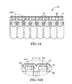
- FIG. 14 is a bottom view of the apparatus of FIG. 2 with analyte capture elements disposed in all but two of the channels.
- FIG. 14A is a bottom detailed view of a portion of the body of FIG. 14 showing a minimum distance between the effluent discharge openings of adjacent outlets.
- FIG. 15 is an exploded upper perspective view of one embodiment of a waste receptacle according to the present disclosure.
- FIG. 16 is a top view of the waste receptacle of FIG. 15 .
- FIG. 16A is a detailed view of a portion of the waste receptacle of FIG. 15 showing a minimum distance between the drains of adjacent chambers.
- FIG. 17 is an exploded perspective view of one embodiment of an assembly for processing a sample according to the present disclosure.
- FIG. 18 is a perspective view of one embodiment of a discharge element according to the present disclosure.
- connection and “coupled” are not restricted to physical or mechanical connections or couplings. It is to be understood that other embodiments may be utilized and structural or logical changes may be made without departing from the scope of the present disclosure. Furthermore, terms such as “front,” “rear,” “top,” “bottom,” and the like are only used to describe elements as they relate to one another, but are in no way meant to recite specific orientations of the apparatus, to indicate or imply necessary or required orientations of the apparatus, or to specify how the invention described herein will be used, mounted, displayed, or positioned in use.
- the present disclosure generally relates to a process of preparing a sample to detect the presence or absence of an analyte.
- the present disclosure provides an apparatus and a method to facilitate a processes of concentrating the analyte by capturing the analyte on and/or in an analyte capture element and, subsequently, detecting the presence or absence of any analyte retained from the sample by the analyte capture element.
- a single step can be used to transfer the resulting retained analyte from the apparatus to a separate container for further processing and/or detection of the analyte.
- the analyte captured using this apparatus and method is relatively concentrated, relatively free of impurities, and is suitable for use in a variety of detection methods (e.g., immunodetection methods and nucleic acid detection methods).
- the present disclosure includes methods and an apparatus for processing a plurality of samples.
- the plurality of samples may comprise samples from independent sources.
- the samples may comprise samples obtained from a single source (e.g., replicate sample; samples removed at different time points; replicate samples that were subjected to different treatments).
- the inventive methods relate to the detection of an analyte in a sample.
- the analyte can be a biological analyte such as, for example, a biological analyte that indicates the presence of a microorganism in the sample.
- the sample can be any sample that may comprise an analyte.
- the analyte may comprise a chemical analyte and/or a biological analyte.
- suitable samples include suspensions or cultures of cells (e.g., mammalian cells, insect cells, yeast cells, filamentous fungi, bacterial cells), environmental samples (e.g., surface swabs), food (e.g., raw materials, in-process samples, and finished-product samples), beverages, clinical samples (e.g., blood, urine, sputum, tissue, mucous, feces, wound exudate, pus), and water (e.g., surface water, potable water, process water).
- cells e.g., mammalian cells, insect cells, yeast cells, filamentous fungi, bacterial cells
- environmental samples e.g., surface swabs
- food e.g., raw materials, in-process samples, and finished-product samples
- beverages e.g., clinical samples (
- Non-limiting examples of suitable biological analytes include nucleic acids (e.g., a polynucleotide associated with a particular type of cell or microorganism) or detectable antigens (e.g., proteins, oligopeptides, enzymes, endotoxin, cell membrane components, and cell wall components). Analytical procedures to detect the biological analytes are known in the art. Preferred biological analytes to be detected include nucleic acids that are capable of being amplified in a reaction (e.g., polymerase chain reaction (PCR)), for example.
- PCR polymerase chain reaction
- test samples may include liquids as well as solid(s) dissolved or suspended in a liquid medium.
- Samples of interest may include process streams, water, soil, plants or other vegetation, air, surfaces (e.g., contaminated surfaces), and the like. Samples can also include cultured cells. Samples can also include samples on or in a device comprising cells, spores, or enzymes (e.g., a biological indicator device).
- Solid samples may be disintegrated (e.g., by blending, sonication, homogenization) and may be suspended in a liquid (e.g., water, buffer, broth).
- a sample-collection device e.g., a swab, a sponge
- the sample material may be eluted (e.g., rinsed, scraped, expressed) from the sample-collection device before using the sample material in the method.
- liquid or solid samples may be diluted in a liquid (e.g., water, buffer, broth).
- Suitable samples also include cell-suspension media (e.g., culture broth, semi-solid cell culture media, and tissue culture media, filtrate) that contain cells or previously contained cells.
- Suitable samples also include cell lysates.
- Cell lysates may be produced by chemical means (e.g., detergents, enzymes), mechanical means (sonic vibration, homogenization, French Press), or by other cell lytic means known in the art.
- Microorganisms are a source of detectable analytes. Microorganisms can be analyzed in a test sample that may be derived from a variety of sources, as described herein. Microorganisms of particular interest include prokaryotic and eukaryotic organisms, particularly Gram positive bacteria, Gram negative bacteria, fungi, protozoa, mycoplasma, yeast, viruses, and even lipid-enveloped viruses.
- Particularly relevant organisms include members of the family Enterobacteriaceae, or the family Micrococcaceae or the genera Staphylococcus spp., Streptococcus spp., Pseudomonas spp., Enterococcus spp., Salmonella spp., Legionella spp., Shigella spp. Yersinia spp., Enterobacter spp., Escherichia spp., Bacillus spp., Listeria spp., Vibrio spp., Corynebacteria spp. as well as herpes virus, Aspergillus spp., Fusarium spp., and Candida spp.
- Particularly virulent organisms include Staphylococcus aureus (including resistant strains such as Methicillin Resistant Staphylococcus aureus (MRSA)), S. epidermidis, Streptococcus pneumoniae, S. agalactiae, S. pyogenes, Enterococcus faecalis , Vancomycin Resistant Enterococcus (VRE), Vancomycin Resistant Staphylococcus aureus (VRSA), Vancomycin Intermediate-resistant Staphylococcus aureus (VISA), Bacillus anthracia, Pseudomonas aeruginosa, Escherichia coli, Aspergillus niger, A.
- MRSA Methicillin Resistant Staphylococcus aureus
- VRE Vancomycin Resistant Enterococcus
- VRSA Vancomycin Resistant Staphylococcus aureus
- VRSA Vancomycin Intermediate-resistant Staphy
- Gram positive and Gram negative bacteria are of particular interest. Of even more interest are Gram positive bacteria, such as Staphylococcus aureus . Also, of particular interest are antibiotic resistant microbes including MRSA, VRSA, VISA, VRE, and MDR.
- FIGS. 1 and 2 show top and bottom perspective views, respectively, of one embodiment of an apparatus 100 for processing a sample.
- the apparatus 100 comprises a body 10 .
- the body 10 has a first end 12 and a second end 14 opposite the first end 12 .
- the body 10 comprises a plurality of spaced-apart reservoirs 20 .
- the reservoirs 20 may form an array such as a linear array of reservoirs 20 , for example, as shown in FIG. 1 .
- Each reservoir 20 in the plurality of reservoirs comprises a sample-receiving opening 22 at the first end 12 and an effluent discharge opening 24 at the second end 14 .
- the body 10 also comprises a plurality of channels 30 , each channel having a first channel opening 32 at the first end 12 of the body 10 .
- Each of the plurality of channels 30 is positioned proximate one of the plurality of reservoirs 20 and substantially aligned with a flow path (not shown) that passes through a reservoir 20 and extends from the first end 12 to the second end 14 of the body 10 .
- the second end 14 of the body 10 comprises a plurality of spaced-apart outlets 28 .
- the outlets 28 may be shaped and dimensioned to be inserted into a predefined container (e.g., a reaction tube, a well of a 96-well plate).
- the plurality of outlets 28 is appropriately dimensioned and spaced-apart such that the plurality of outlets 28 can be inserted (e.g., simultaneously) into a linear array of two or more tubes (e.g., a plurality of reaction tubes such as a linear array of 1.1 mL minitubes, part number MTS-8-C-R, available from Axygen, Inc. Union City, Calif., for example).
- the tubes of the linear array may have a center-to-center distance of about 9 mm or less. In some embodiments, the tubes of the linear array may have a center-to-center distance of about 2 mm to about 20 mm.
- the volume of the reservoirs 20 can be configured according to the typical size of the sample to be tested. In some embodiments, the volume of the reservoir 20 is at least about one milliliter. In some embodiments, the volume of the reservoir 20 is at least about five milliliters. In some embodiments, the volume of the reservoir 20 is at least about ten milliliters. In some embodiments, the volume of the reservoir 20 is at least about twenty-five milliliters. In some embodiments, the volume of the reservoir 20 is at least about one hundred milliliters. Larger volumes of liquid sample can be tested by passing two or more aliquots of the sample sequentially through the same reservoir 20 .
- the cover 80 protects each reservoir 20 from the entry of undesirably material.
- the cover 80 may comprise a thin sheet (e.g., a plastic film or coated paper).
- the cover 80 is attached (e.g., removably attached) to the body 10 via a heat bond or a pressure-sensitive adhesive, for example.
- the cover 80 may comprise a pierceable film (e.g., pierceable by a pipette tip) and or the cover may be optically translucent or transparent, thereby permitting visualization of contents present in the reservoirs 20 .
- FIG. 3 is a cross-sectional view of the body 10 of the apparatus 100 of FIG. 1 .
- the reservoir 20 has an opening 22 through which a sample (e.g., a liquid sample or a suspension of solid material in a liquid, not shown) is deposited into the reservoir 20 .
- a sample e.g., a liquid sample or a suspension of solid material in a liquid, not shown
- FIG. 3 Also shown in FIG. 3 are a channel 30 and an effluent discharge opening 24 , which are both in fluid communication with the reservoir 20 via a conduit 26 .
- the apparatus 100 of the present disclosure defines a liquid flow path (e.g., a liquid flow path), shown by the arrows, extending from the sample-receiving opening 22 at the first end 12 of the body 10 to the effluent discharge opening 24 at the second end 14 of the body 10 .
- each of the second channel opening and effluent discharge opening comprise separate openings proximate the second end of the body.
- the apparatus 100 further may comprise a prefilter 50 .
- the prefilter 50 substantially remove particulate materials that are larger than a bacterium (e.g., ⁇ 5 mm diameter) serves to trap and substantially remove particulate materials that are larger than a bacterium (e.g., ⁇ 5 ⁇ m diameter) that may be present in a liquid sample passing there through.
- the reservoir 20 is configured such that a liquid sample moving through the reservoir 20 from the sample-receiving opening 22 to the effluent discharge opening 24 substantially passes through the prefilter 50 .
- the prefilter 50 can be supported by the optional base 25 .
- the prefilter 50 optionally may be coupled (e.g., via an adhesive or other secural means, not shown) to the base 25 .
- a gutter 27 in the base 25 is also shown in FIG. 3 . The gutter 27 is described in further detail below.
- the prefilter 50 can be constructed from a variety of materials known in the art (e.g., nonwoven materials comprising nylon, polypropylene, glass, or cellulose acetate fibers, for example; or perforated films such as polycarbonate films, for example).
- the prefilter 50 may comprise a single layer of material.
- the prefilter 50 may comprise a plurality of layers (not shown).
- a layer of a prefilter comprising a plurality of layers may comprise a particulate material to facilitate the removal of certain non-analyte materials (e.g., fats, minerals) from the sample.
- the prefilter 50 may comprise a membrane filter or a relatively coarse nonwoven depth filter (approximately 1 mm thick) made from polyethylene fibers.
- the prefilter 50 or layer thereof may have a nominal porosity of approximately 20-50 ⁇ m and can function to prevent the passage of large particles into other layers of the prefilter, if present.
- the prefilter 50 , or layer thereof may comprise a wet-laid fibrous scaffold (approximately 0.2-1 mm thick), optionally containing particulate material that removes a one or more specific non-analyte materials.
- a non-limiting example of a material that may be used in a prefilter 50 individually or in any combination with other materials is a polypropylene felt filter (part number NB005PPS2R, 5 ⁇ m nominal porosity, available from CUNO 3M, Meriden, Conn.).
- a polypropylene felt filter part number NB005PPS2R, 5 ⁇ m nominal porosity, available from CUNO 3M, Meriden, Conn.
- Other known layers (not shown) and/or materials may be used in prefilter 50 , with each layer functioning to reduce the amount of non-analyte material in the liquid sample as it passes through the prefilter 50 .
- FIG. 5 shows a top view of the apparatus of FIG. 1 .
- the body 10 comprises a plurality of reservoirs 20 and a plurality of channels 30 arranged in side-by-side linear arrays.
- Each reservoir 20 comprises a sample-receiving opening 22 and a conduit 26 , which form part of the liquid flow path (designated by arrows) shown in FIG. 3 .
- the base 25 on which a prefilter (not shown) can be disposed.
- the base 25 further can comprise one or more gutters 27 , which may comprise, for example, depressions that extend along the base 25 away from the conduit 26 in one or more directions. In use, the gutters 27 guide liquid along the base toward the conduit 26 .
- the apparatus of the present disclosure further can comprise an analyte capture element.
- FIG. 6 shows a perspective view of one embodiment of an analyte capture element 40 according to the present disclosure.
- FIG. 7 shows an exploded cross-sectional side view of the analyte capture element 40 of FIG. 6 .
- the analyte capture element 40 comprises a capture medium 42 and, optionally, a holder 44 .
- the holder 44 is a frame-like structure comprising two portions ( 44 a and 44 b , respectively) that are press-fit together and, when joined, securely hold the capture medium 42 .
- the holder 44 has a first face 45 , a second face 46 , and a longitudinal plane 47 between the first face 45 and the second face 46 .
- the capture medium 42 is disposed in the holder 44 substantially along the longitudinal plane 47 .
- the capture medium 42 can be attached (e.g., detachably attached) to the holder 44 via an adhesive (e.g., a pressure sensitive adhesive), an ultrasonic weld, a heat bond, and/or an insert mold at any point on the holder 44 .
- an adhesive e.g., a pressure sensitive adhesive
- an ultrasonic weld e.g., a heat bond
- an insert mold e.g., a heat bond
- the capture medium 42 can be disposed on the holder 44 substantially along the first 45 or second face 46 .
- the capture medium 42 can be attached along an edge 48 of the first face 45 of the holder 44 .
- the capture medium can be disposed in the holder in a plane that is oriented from a portion of the first face to a portion of the second face (e.g., diagonal to the longitudinal plane shown in FIG. 7 .
- the holder 44 may be fabricated from a variety of materials using methods that are well known in the art.
- the holder 44 may be constructed using polymeric resin materials (e.g., polypropylene, polyethylene, and/or polycarbonate) in a molding process.
- the capture medium 42 comprises a material configured to capture and retain a target analyte (e.g., a microorganism or a biological analyte derived from a microorganism).
- a target analyte e.g., a microorganism or a biological analyte derived from a microorganism.
- the capture medium 42 comprises a porous material (e.g., a filter membrane, a porous sheet material) that permits the passage of liquids there through but retains particles of a selected size (e.g., particles that are approximately the size of bacteria such as about 0.5 to about 5 ⁇ m, for example).
- the capture medium 42 can be one or more of a variety of membrane-type filters (e.g., cellulose acetate filters, nylon filters, nitrocellulose filters, polycarbonate filters, ceramic filters, polysulfone filters, nanofiber filter, and/or a TIPS membrane similar to those described in PCT Patent Publication No. WO2010/078234), for example.
- membrane-type filters e.g., cellulose acetate filters, nylon filters, nitrocellulose filters, polycarbonate filters, ceramic filters, polysulfone filters, nanofiber filter, and/or a TIPS membrane similar to those described in PCT Patent Publication No. WO2010/078234
- suitable membrane-type filters are the VERSAPOR 3000TN membrane (3 ⁇ m nominal porosity) and the VERSAPOR 800 membrane (0.8 ⁇ m nominal porosity), both available from Pall Life Sciences, Port Washington, N.Y.).
- other pore sizes may be useful (e.g., 0.45 ⁇ m nominal porosity, 0.2 ⁇ m nominal po
- membrane-type filters represent a preferred embodiment of the capture medium 42 of the present disclosure
- the capture medium 42 may comprise depth-type filters, which may be relatively thicker than the membrane-type filters illustrated in FIGS. 6-7 .
- the analyte capture element 40 may comprise a binding partner (e.g., a polyclonal antibody, a monoclonal antibody, a receptor, a lectin, an antibiotic, a bacteriophage, an aptamer) coupled, either directly or indirectly, there to.
- the analyte capture element 40 may comprise a capture medium 42 (e.g., a membrane) that includes functional groups to which an antibody is covalently or noncovalently attached.
- the binding partner may provide the specificity to bind a particular target analyte.
- the analyte capture element 40 may comprise a capture medium 42 comprising a plurality of layers.
- the binding partner may be disposed (e.g., on and/or in a particle or a hydrogel) between two layers of the capture medium 42 .
- the analyte-capture element 40 may comprise a particulate material (e.g., a fiber, a particle, a bead) or a nonporous sheet material (e.g., a polymer film) configured to bind to a target analyte.
- the particulate or sheet materials may be disposed between two layers of the capture medium 42 , as described above.
- the particulate material may be porous.
- the particulate material may be nonporous.
- the analyte-capture element 40 may comprise a combination of porous and nonporous particulate materials.
- the particulate material may bind the target analyte relatively non-specifically.
- Certain particulate cell concentration agents are known in the art and are suitable for use in methods of the present disclosure.
- suitable cell concentration agents include activated charcoal, hydroxyapatite (Berry et al.; Appl. Environ. Microbiol.; 63:4069-4074; 1997), magnetic beads (Oster et al., J. Magnetism and Magnetic Mat.; 225:145-150; 2001), ferrimagnetic mineral, magnetite, chitosan, and affinity supports.
- the use of compositions including an immobilized-metal support material to capture or concentrate microorganisms from a sample is described in PCT Patent Publication No.
- the cell concentration agent may be held on or in a scaffold material such as a wet-laid fiber such as cellulose, for example.
- Exemplary particulate materials further include diatomaceous earth and surface treated diatomaceous earth. Specific examples of such concentration agents can be found in commonly assigned PCT Patent Publication No. WO 2009/046191, entitled “MICROORGANISMS CONCENTRATION PROCESS AND AGENT”; the disclosure of which is incorporated herein by reference.
- concentration agents can be found in commonly assigned PCT Patent Publication No. WO 2009/046191, entitled “MICROORGANISMS CONCENTRATION PROCESS AND AGENT”; the disclosure of which is incorporated herein by reference.
- zeta potential The potential across the material-water interface is called the “zeta potential,” which can be calculated from electrophoretic mobilities (that is, from the rates at which the particles of material travel between charged electrodes placed in the water system).
- concentration agents can have zeta potentials that are at least somewhat more positive than that of untreated diatomaceous earth, and the concentration agents can be surprisingly significantly more effective than untreated diatomaceous earth in concentrating microorganisms such as bacteria, the surfaces of which generally tend to be negatively charged.
- the particulate material may comprise a binding partner coupled thereto and the binding partner may provide the specificity for binding a particular target analyte.
- the particulate material may be incorporated into a matrix (e.g., beads entrapped in a fibrous matrix).
- a matrix e.g., beads entrapped in a fibrous matrix.
- the analyte capture element can be disposed in an apparatus of the present disclosure.
- FIG. 8 shows a lower perspective view of the apparatus 100 of FIG. 2 , wherein the apparatus 100 has one of a plurality of analyte capture elements 40 disposed in each of the plurality of channels 30 proximate the second end 14 of the body 10 .
- FIG. 9 shows a cross-sectional view of the apparatus 100 of FIG. 8 .
- FIG. 10 shows a detailed cross-sectional view of the view of the apparatus 100 of FIG. 9 .
- the analyte capture element 40 is disposed in the channel 30 such that the capture medium 42 transects a flow path (shown by arrows) extending from the sample-receiving opening 22 of the reservoir 20 through the conduit 26 to the effluent discharge opening 24 .
- the capture medium 42 is a porous membrane, for example, a liquid sample (not shown) passing from the first end 12 to the second end 14 of the body 10 passes through the capture medium 42 .
- the liquid sample comprises a target analyte (e.g., a target microorganism or a portion thereof), the target analyte can be captured by the analyte capture element 40 .
- a target analyte e.g., a target microorganism or a portion thereof
- FIGS. 11A and 11B each show detailed cross-sectional side views of the second end 14 of an apparatus 100 of the present disclosure.
- an alternative analyte capture element 40 ′ is disposed in the channel 30 proximate the second end 14 of the body 10 .
- the analyte capture element 40 ′ comprises a capture medium 42 (e.g., a porous membrane, positioned along one edge of the analyte capture element 40 ′.
- the capture medium 42 can be positioned in the flow path proximate the effluent discharge opening 24 (as shown in FIG. 11A ) or the capture medium 42 can be positioned in the flow path proximate the conduit 26 (as shown in FIG. 11B ).
- particulate material 99 is trapped in the conduit 26 by the capture medium 42 and the resulting trapped particulate material 99 can be substantially retained in the conduit 26 as the analyte capture element 40 ′ is ejected from the second channel opening 34 of the body 10 .
- particulate material 99 is trapped in the channel 30 by the capture medium 42 and the resulting trapped material can be substantially ejected with the analyte capture element 40 ′ when the capture element 40 ′ is ejected from the second channel opening 34 of the body 10 .
- This particulate material 99 may be ejected with the analyte capture element 40 and, optionally, can be processed likewise to determine whether a target analyte is present in the particulate material 99 trapped by the analyte capture element 40 .
- this feature provides increased sensitivity for the detection of target analyte in the sample material.
- an apparatus according to the present disclosure may further comprise a structure to retain (e.g., releasably retain) the analyte capture element at a predetermined location in a channel.
- FIG. 12A shows a cross-sectional side view of the second end 14 of one embodiment of an apparatus 100 ′ comprising a first retention structure 36 disposed in the channel 30 such that the conduit 26 opens into the channel 30 at a location between the first retention structure 36 and the second channel opening 34 .
- the first retention structure 36 may be formed from the same material as the body 10 of the apparatus 100 ′, optionally during a molding process that forms the body 10 .
- the first retention structure 36 may be attached (e.g., via an adhesive, ultrasonic welding, or other means known in the art) after the body 10 is formed.
- an analyte capture element analyte capture element 40 , shown in FIG. 12C
- This resistance signals that the analyte capture element is properly positioned for use in the apparatus 100 ′ (e.g., the analyte capture element is positioned at a location that is in fluid communication with a flow path that intersects the channel 30 in which the analyte capture element is disposed).
- the first retention structure 36 and/or the analyte capture element can configured so that the analyte capture element can continue moving through the channel 30 past the first retention structure 36 .
- the first retention structure 36 and/or the analyte capture element can be fabricated from a relatively soft material (e.g., polypropylene, polyethylene) such that the first retention structure 36 and/or the analyte capture element can deform sufficiently to permit the analyte capture element to move while contacting the first retention structure 36 , provided the analyte capture element is urged with sufficient force to overcome the frictional resistance.
- any apparatus according to the present disclosure may further comprises a second retention structure to retain (e.g., releasably retain) the analyte capture element at a predetermined location in a channel.
- FIG. 12B shows a cross-sectional side view of the second end 14 of one embodiment of an apparatus 100 ′′ comprising a first retention structure 36 and a second retention structure 38 disposed in the channel 30 .
- the second retention structure 38 is positioned between the conduit 26 and the second channel opening 34 .
- the second retention structure 38 may be formed from the same material as the body 10 of the apparatus 100 ′′, optionally during a molding process that forms the body 10 .
- the second retention structure 38 may be attached (e.g., via an adhesive, ultrasonic welding, or other means known in the art) after the body 10 is formed.
- an analyte capture element analyte capture element 40 , shown in FIG. 12C
- the analyte capture element and/or the second retention element 38 can deform sufficiently to permit the analyte capture element to continue moving into the channel 30 until it contacts the first retention element 36 .
- the analyte capture element 40 is properly positioned for use in the apparatus 100 ′′ (e.g., the analyte capture element is releasably engaged at a location that is in fluid communication with a flow path that intersects the channel 30 in which the analyte capture element 40 is disposed, as shown in FIG. 12C ).
- an analyte capture element When used in a method according to the present disclosure, an analyte capture element can be ejected from the channel to detect the presence or absence of a target analyte retained by the analyte capture element.
- the ejection process can be facilitated by using a discharge element that is configured to move through the channel, contact the analyte capture element, and urge the analyte capture element out of the channel.
- FIG. 18 shows one embodiment of a capture element discharger 300 comprising an optional handle 90 and one or more posts 92 .
- the posts 92 are suitably dimensioned and spaced apart such that they can be inserted (e.g., inserted simultaneously) into a plurality of first channel openings in the apparatus of FIG. 1 .
- the handle 90 can be used to urge the post 92 toward the body of the apparatus, causing the post 92 to move through the channel until it contacts an analyte capture element, if present, in the channel. Urging the post 92 further into the channel causes the post 92 to eject the analyte capture element out the second channel opening 34 of the body 10 .
- the discharge element 300 may be fabricated as a unitary device having one or more posts or the handle may be fabricated separately and coupled to one or more posts 92 using any suitable coupling means (e.g., adhesive, sonic weld, clip, staple, pin, screw, or the like) known in the art.
- the posts 92 can be fabricated individually, optionally with a handle 90 , or individual posts 92 may be coupled to a handle 90 as described above.
- the parts (handle 90 and posts 92 ) may be fabricated from wood, metal, or plastic, for example.
- the posts 92 can preferably be dimensioned to extend approximately at least the length of the channel, thereby ensuring it can fully displace and eject the analyte capture element from the channel.
- the posts 92 are shaped and dimensioned to seal the conduit while ejecting the analyte capture element from the apparatus.
- the second channel opening and effluent discharge opening comprise separate openings proximate the second end of the body.
- FIG. 13 shows a cross-sectional view of the second end 14 of one embodiment of an apparatus 101 comprising separate openings for the second channel opening 34 and the effluent discharge opening 24 ′. Also shown in FIG. 13 are a flow path (arrows), a portion of the reservoir 20 , the conduit 26 that fluidically connects the reservoir 20 with the channel 30 , a portion of the channel 30 , the outlet 28 ′, and an analyte capture element 40 comprising a capture medium 42 (e.g., a porous membrane).
- a capture medium 42 e.g., a porous membrane
- the outlet 28 ′ extends from the body 10 sufficiently enough to permit attachment to a vacuum source (e.g., tubing connected to a vacuum pump, not shown).
- a vacuum source e.g., tubing connected to a vacuum pump, not shown.
- the analyte capture element 40 is slideably engaged in the channel 30 and can be ejected from the channel 30 for analysis after a liquid sample (not shown) has contacted the analyte capture element 40 .
- the apparatus may further comprise a frangible seal (not shown) proximate the second channel opening.
- the frangible seal can be fabricated from a polymeric or metal film and can be coupled to the second end of the body via a pressure sensitive adhesive, for example.
- FIG. 14 shows a bottom view of the apparatus 100 of FIG. 8 .
- FIG. 14A shows a detailed view of two adjacent outlets 28 .
- Each of the adjacent outlets 28 has an analyte capture element 40 disposed in the channel 30 proximate the second channel opening 34 .
- Each of the adjacent outlets (outlets 28 a and 28 b , respectively) also comprises an effluent discharge opening ( 24 a and 24 b , respectively).
- X minimum distance
- any apparatus of the present disclosure with an analyte capture element disposed in at least one of the plurality of channels, can be used in an assembly for processing a sample.
- the assembly can comprise a waste receptacle configured to be operationally coupled to the apparatus.
- the waste receptacle can receive a liquid effluent from at least one of the plurality of outlets of the apparatus.
- FIG. 15 shows an upper perspective view
- FIG. 16 shows a top view of one embodiment of a waste receptacle 200 according to the present disclosure.
- the waste receptacle 200 comprises a plurality of spaced-apart chambers 60 .
- the number of chambers 60 corresponds to the number of outlets present in the apparatus to which the waste receptacle 200 will be operationally coupled.
- the spacing and dimensions of the chambers 60 are selected such that the chambers 60 can receive liquid streams from at least two adjacent outlets and substantially prevent the separate liquid streams from contacting each other.
- the waste receptacle 200 optionally may comprise a flange 70 .
- the flange 70 may be configured to form a tight fit with the apparatus (not shown) to facilitate a sufficient seal to prevent leakage and to permit vacuum suction to be transmitted from the waste receptacle 200 to the apparatus.
- the flange 70 may position and retain an optional gasket 85 .
- the gasket 85 comprises holes 86 dimensioned to receive the outlets of any one of the apparatuses described herein.
- the gasket 85 can be fabricated from a conformable material (e.g., butyl rubber) and can facilitate the formation of a vacuum seal between the waste receptacle 200 and an apparatus (not shown) according to the present disclosure.
- the waste receptacle 200 further may comprise a vent 74 .
- the vent 74 may be adapted to be connected to a source of negative pressure (e.g., a vacuum pump).
- the adaptations may comprise for example, shaping and dimensioning the vent 74 so that it can be attached to a vacuum hose.
- the vent 74 may comprise ribs 75 to retain a vacuum hose.
- the waste receptacle 200 may further comprise a receptacle base 78 to support the receptacle on a surface.
- Each of the plurality of chambers 60 has at least one wall 61 defining an outlet-receiving opening 62 .
- the chamber further may comprise a floor 64 .
- the floor 64 may be substantially planar.
- the at least one wall 61 and, if present, optional floor 64 define an interior volume of the chamber 60 .
- Each chamber 60 further comprises a drain 66 , which is an opening to direct the flow of liquid (e.g., by gravity or by vacuum suction) out of the chamber 60 .
- the drains 66 are positioned in the floor 64 of the chamber 60 .
- the floor 64 further may comprise a trough 68 to direct the flow of liquid along the floor 64 to the drain 66 .
- the drain openings may be located in the walls of the chambers.
- FIG. 16A shows a detailed top view of two adjacent chambers ( 60 a and 60 b , respectively) in the waste receptacle 200 of FIGS. 15 and 16 .
- the chambers 60 a and 60 b each have a wall 61 , floor 64 , drain ( 66 a and 66 b , respectively), and trough 68 .
- Y minimum distance
- the waste receptacle 200 can be fabricated by injection molding, for example, from polymeric material (e.g., polyethylene, polypropylene, polystyrene, and/or polycarbonate). Alternatively, the waste receptacle 200 can be fabricated using glass or metal.
- polymeric material e.g., polyethylene, polypropylene, polystyrene, and/or polycarbonate.
- the waste receptacle 200 can be fabricated using glass or metal.
- FIG. 17 shows an exploded perspective view of one embodiment of an assembly 1000 for processing a sample, according to the present disclosure.
- the assembly 1000 comprises an apparatus 100 comprising a plurality of reservoirs 20 according to any one of the embodiments described herein, at least one capture element 40 slideably engaged in one of the channels 30 , and a waste receptacle 200 comprising a plurality of chambers 60 according to any one of the embodiments described herein.
- the apparatus 100 comprises a first reservoir 20 a in fluidic communication with a first outlet 28 a and a second reservoir 20 b in fluidic communication with a second outlet 28 b .
- the waste receptacle 200 comprises a first chamber 60 a and a second chamber 60 b , the first chamber 60 a having a first interior volume and the second chamber 60 b having a second interior volume.
- the first chamber 60 a comprises a first drain (not shown) and second the chamber 60 b comprises a second drain ( 66 b ).
- this configuration substantially can prevent cross-contamination of separate liquid streams passing through (e.g., passing through either simultaneously or sequentially) the first outlet 28 a and second outlet 28 b , respectively, or cross-contamination of analyte capture elements disposed in adjacent outlets, by physically isolating the respective outlets (and analyte capture elements disposed therein) in separate chambers.
- the first and second outlets ( 28 a and 28 b , respectively) each comprise a first effluent discharge opening (not shown) and a second effluent discharge opening (not shown), respectively, as described herein.
- the first shortest distance is shorter than the second shortest distance.
- this configuration further reduces the probability of cross-contamination between separate liquid streams passing through (e.g., passing through either simultaneously or sequentially) the first outlet 28 a and second outlet 28 b , respectively, by causing greater physical separation of the liquid streams as they pass out of the respective drains.
- each of the plurality of chambers 60 may comprise a substantially planar floor, as described herein.
- the floor may comprise the drain.
- the floor further may comprise a trough (not shown), as described herein.
- the waste receptacle 200 may be adapted to be coupled to a source of negative pressure, as described herein.
- the present disclosure includes a method of detecting a presence or an absence of an analyte in a sample.
- the method comprises providing a liquid sample and an apparatus or an assembly, said apparatus or assembly with at least one analyte capture element moveably (e.g., slideably) engaged in a channel according to any of the embodiments described herein.
- the method of the present disclosure further comprises contacting the liquid sample with the at least one analyte capture element.
- contacting the liquid sample with the at least one analyte capture element comprises loading the sample into a reservoir that is in fluidic communication with the at least one analyte capture element and permitting the liquid sample to flow through the apparatus from the reservoir to the effluent discharge opening and out of the apparatus. While flowing from the reservoir to the effluent discharge opening, the liquid sample contacts the analyte capture element.
- the liquid sample passes through the analyte capture element while contacting it.
- the liquid sample can pass through the device by gravity flow.
- the liquid can be urged to pass through the apparatus by applying positive or negative pressure.
- the method further can comprise the step of operably connecting the apparatus or the assembly to a source of negative pressure, as described herein.
- the at least one capture element comprises a porous medium.
- contacting the liquid sample with the at least one capture element can comprise passing the liquid sample through the porous medium.
- the method of the present disclosure further comprises ejecting the at least one analyte capture element from the channel.
- Ejecting the at least one analyte capture element can comprise sliding the capture element out of an opening at the second end of the apparatus (e.g., the second channel opening shown in FIG. 3 ).
- an accessory tool e.g., forceps, a pipette tip
- ejecting the at least one analyte capture element from the channel can comprises moving a portion of a discharge element through a portion of the channel to eject the analyte capture element from the channel.
- the discharge element can comprise a portion (e.g. a post, such as a solid post, shaped and dimensioned to fit in the channel) configured to move through the channel, contact the analyte capture element, and urge the analyte capture element out of the channel, as described herein.
- the method of the present disclosure further comprises detecting a presence or an absence an analyte retained from the sample by the analyte capture element.
- Detecting the presence or absence of an analyte can comprise detecting the presence or absence of an analyte associated (e.g., exclusively associated) with a cell of interest (e.g., a microbial cell).
- the analyte may comprise a nucleotide (e.g., ATP), a nucleic acid (e.g., DNA, RNA, mRNA, and/or an oligonucleotide), an enzyme, or an antigen associated with a cell of interest.
- detecting a presence or an absence an analyte retained from the sample may comprise detecting a nucleotide, a nucleic acid, an enzyme, and/or an antigen associated with a cell of interest.
- detecting a presence or an absence an analyte retained from the sample may comprise detecting a nucleotide, a nucleic acid, an enzyme, and/or an antigen associated with a cell of interest.
- the method further can comprise processing the at least one analyte capture element and/or sample material associated therewith to permeabilize a cell.
- processing the at least one analyte capture element and/or sample material associated therewith to permeabilize a cell.
- the analyte capture element and, if present, any sample material associated therewith can be treated to permeabilize a cell. This can be performed, for example, by contacting the analyte capture element and/or sample material with a lysing agent (e.g., a detergent, an enzyme).
- a lysing agent e.g., a detergent, an enzyme
- the analyte capture element and, if present, any sample material associated therewith can be treated mechanically (e.g., by heat, sonication, freeze/thaw) to permeabilize a cell. Permeablizing the cells can improve the detection of an analyte associated with a cell of interest.
- the method further can comprise the step of coupling at least one outlet to a container.
- the container may be a reaction tube or a linear array of reaction tubes, for example, in which the analyte capture element can be processed to detect the presence or absence of an analyte.
- ejecting the at least one analyte capture element from the channel can comprise ejecting the analyte capture element into the container.
- this feature of the apparatus and method can substantially prevent contamination of the analyte capture element with materials that were not present in the sample when the analyte capture element is transferred to a container.
- the apparatuses or assemblies of the present disclosure can be used according to the method to process a plurality of samples.
- the plurality of samples may be processed simultaneously.
- the analyte may be a whole microorganism such as a bacterium, for example. In some embodiments, the analyte may be a living microorganism. In these embodiments, it may be desirable to detect the microorganism by culture techniques. Accordingly, the microorganisms may be detached or eluted from the analyte-capture element by rinsing and/or homogenizing the analyte-capture element in a suspending medium (water, buffer, buffered saline, liquid culture media).
- a suspending medium water, buffer, buffered saline, liquid culture media.
- the liquid suspending medium could be used to inoculate culture media (e.g., the appropriate agar culture medium) to determine the presence, absence or quantity of target microorganisms that were in the original sample.
- the analyte-capture medium could be transferred directly onto culture media for growth and analysis. Accordingly, when the analyte-capture element is separated from the apparatus by ejecting the analyte-capture element into a container, the container may include a suspending medium therein.
- the analyte may be a whole microorganism or a portion of a microorganism (e.g., a cell wall or a fragment thereof, a cell membrane or a fragment thereof, a protein, or a polysaccharide).
- a microorganism e.g., a cell wall or a fragment thereof, a cell membrane or a fragment thereof, a protein, or a polysaccharide.
- an immunodiagnostic method e.g., ELISA, immunochromatography
- the container may include a suspending medium, a cell lysis reagent (e.g., an acid, a base, a detergent, an enzyme, a protease, lysozyme, lysostaphin), and/or an analyte-specific binding partner (e.g., an antibody, a receptor) therein.
- a cell lysis reagent e.g., an acid, a base, a detergent, an enzyme, a protease, lysozyme, lysostaphin
- an analyte-specific binding partner e.g., an antibody, a receptor
- the analyte may be an enzyme or an enzyme substrate (e.g., ATP) associated with a particular microorganism or group of microorganisms. In these embodiments, it may be desirable to detect the analyte using an enzyme assay.
- an enzyme substrate e.g., ATP
- the container may include a suspending medium, a cell lysis reagent (e.g., an acid, a base, a detergent, an enzyme, a protease, lysozyme, lysostaphin), an enzyme (e.g., luciferase, adenylate kinase) and/or an enzyme substrate (e.g., a luciferin, a chromogenic enzyme substrate, or a fluorogenic enzyme substrate) therein.
- a cell lysis reagent e.g., an acid, a base, a detergent, an enzyme, a protease, lysozyme, lysostaphin
- an enzyme e.g., luciferase, adenylate kinase
- an enzyme substrate e.g., a luciferin, a chromogenic enzyme substrate, or a fluorogenic enzyme substrate
- the analyte may be a microorganism-associated polynucleotide (e.g., DNA or RNA).
- a microorganism-associated polynucleotide e.g., DNA or RNA
- it may be desirable to detect the analyte using nucleic acid detection methods known in the art e.g., PCR, rtPCR, LCR, NASBA, blot analysis.
- the container may include a suspending medium, a cell lysis reagent (e.g., an acid, a base, a detergent, an enzyme, a protease, lysozyme, lysostaphin), an analyte-specific probe, an analyte-specific primer and/or an enzyme and a reagent for amplifying or labeling a polynucleotide therein.
- a cell lysis reagent e.g., an acid, a base, a detergent, an enzyme, a protease, lysozyme, lysostaphin
- an analyte-specific probe e.g., an analyte-specific primer and/or an enzyme and a reagent for amplifying or labeling a polynucleotide therein.
- the method further can comprise an enrichment step.
- the enrichment step can comprise providing a culture medium to facilitate the growth of a target microorganism and a latent effervescent body comprising a selective agent, as described in PCT Patent Publication No. WO2012/092123, which is incorporated herein by reference in its entirety.
- the present disclosure also provides a kit for processing a sample.
- the kit can comprise any apparatus according to the present disclosure to be used in a method of processing a sample according to the present disclosure.
- the kit further may comprise one or more analyte capture elements configured to be slideably engaged in a channel of the apparatus.
- the kit further may comprise an analyte capture element discharger.
- the kit further may comprise a reagent.
- the reagent may comprise a cell lysis agent, or a detection agent.
- the detection agent may comprise, for example, an oligonucleotide, a labeled oligonucleotide, an enzyme substrate, a binding partner (e.g., an antibody, a receptor), and/or a labeled binding partner.
- a binding partner e.g., an antibody, a receptor
- Embodiment A is an apparatus for processing a sample, comprising:
- each reservoir comprising a sample-receiving opening
- each effluent discharge opening in fluid communication with one of the plurality of sample-receiving openings via a flow path;
- each channel intersecting one of the flow paths
- each channel comprises a second channel opening proximate the second end
- each channel is dimensioned to receive a analyte capture element
- each of the outlets comprising one of the second channel openings.
- Embodiment B is the apparatus of Embodiment A, wherein each of the outlets further comprises one of the effluent discharge openings.
- Embodiment C is the apparatus of Embodiment A or Embodiment B, wherein the effluent discharge opening and the second channel opening define a common opening.
- Embodiment D is the apparatus of any one of the preceding Embodiments, further comprising an analyte capture element slideably engaged in a channel at a location that is in fluid communication with the flow path that intersects the channel in which the analyte capture element is disposed.
- Embodiment E is the apparatus of Embodiment D, wherein the analyte capture element comprises a holder with a capture medium attached thereto.
- Embodiment F is the apparatus of any one of the preceding Embodiments, wherein the apparatus further comprises a first retention structure disposed in a channel, wherein the first retention structure is configured to position a analyte capture element, if present, at a location in the channel where the analyte capture element is in fluid communication with the flow path that intersects the channel.
- Embodiment G is the apparatus of Embodiment F, further comprising a second retention structure disposed in the channel, wherein the first and second retention structures are configured to releasably hold the analyte capture element, if present, at a location where the analyte capture element is in fluid communication with the flow path.
- Embodiment H is the apparatus of any one of Embodiments D through G, wherein the analyte capture element comprises an analyte binding reagent.
- Embodiment I is the apparatus of any one of Embodiment D through H, wherein the apparatus is configured such that substantially all liquid passing through the flow path from the sample-receiving opening to the effluent discharge opening passes through the analyte capture element.
- Embodiment J is the apparatus of any one of Embodiments E through I;
- the holder comprises a first face, a second face opposite the first face, and a longitudinal plane between the first face and the second face;
- the capture medium is disposed in the holder substantially along the longitudinal plane.
- Embodiment K is the apparatus of any one of Embodiments F through I;
- the holder comprises a first face, a second face opposite the first face;
- the capture medium is disposed on the holder substantially along the first or second face.
- Embodiment L is the apparatus of any one of Embodiments E through I;
- the holder comprises a first face, a second face opposite the first face, and a longitudinal plane between the first face and the second face;
- the capture medium is disposed in the holder in a plane that is oriented from a portion of the first face to a portion of the second face.
- Embodiment M is the apparatus of any one of the preceding Embodiments, wherein the channel extends from the second channel opening to a first channel opening.
- Embodiment N is the apparatus of Embodiment M, wherein the first channel opening is disposed at the first end.
- Embodiment O is the apparatus of any one of the preceding Embodiments, further comprising an analyte capture element discharger comprising a post, wherein a portion of the post is disposed in the channel, wherein the discharger is configured to move through the channel and to urge an analyte capture element, if present in the channel, out of the second channel opening.
- Embodiment P is the apparatus of any one of the preceding Embodiments, wherein the sample-receiving opening of each of the plurality of chambers is covered with a pierceable seal.
- Embodiment Q is the apparatus of any one of the preceding Embodiments, further comprising a prefilter disposed in a flow path between the sample-receiving opening of the flow path and the channel that intersects the flow path.
- Embodiment R is the apparatus of any one of the preceding Embodiments, wherein each outlet of the plurality of outlets is shaped, dimensioned, and spaced apart such that the plurality of outlets can be received into a linear array of two or more tubes.
- Embodiment S is the apparatus of Embodiment R, wherein the tubes in the linear array have a center-to-center distance of about 9 mm or less.
- Embodiment T is the apparatus of embodiment S, wherein each of the tubes has a circular opening, wherein the circular opening has an inner diameter of about 2 mm to about 7 mm.
- Embodiment U is an assembly, comprising:
- the apparatus of any one of the preceding Embodiments, wherein the apparatus comprises:
- a first reservoir having a first sample-receiving opening and a first outlet having a first effluent discharge opening
- the second reservoir having a second sample-receiving opening and a second outlet having a second effluent discharge opening;
- the waste receptacle comprises a plurality of spaced-apart chambers, wherein the plurality of spaced-apart chambers comprises:
- a first chamber having a first interior volume and a first drain
- the second chamber having a second interior volume and a second drain;
- an analyte capture element slideably engaged in one of the channels
- a first liquid flow path extends from the first sample-receiving opening to the first drain, and a second liquid flow path extends from the second sample-receiving opening to the second drain;
- a first shortest distance between the first effluent discharge opening and the second effluent discharge opening is shorter than a second shortest distance between the first drain and the second drain.
- Embodiment V is the assembly of Embodiment U wherein, when the apparatus and the waste receptacle are operably coupled, at least a portion of the first outlet is disposed in the first interior volume and at least a portion of the second outlet is disposed in the second interior volume.
- Embodiment W is the assembly of Embodiment U or Embodiment V, wherein each of the plurality of chambers comprises a substantially planar floor, wherein the floor comprises the drain.
- Embodiment X is the assembly of embodiment W, wherein the floor further comprises a trough extending along a portion of the floor to the drain.
- Embodiment Y is the assembly of any one of Embodiments U through X, wherein the waste receptacle is adapted to be coupled to a source of negative pressure.
- Embodiment Z is a method of detecting a presence or an absence of an analyte in a sample, the method comprising:
- analyte capture element detecting a presence or an absence an analyte retained from the sample by the analyte capture element.
- Embodiment AA is the method of Embodiment Z, wherein contacting the liquid sample with the at least one analyte capture element comprises loading the sample into a reservoir that is in fluidic communication with the at least one analyte capture element.
- Embodiment BB is the method of Embodiment Z or Embodiment AA, further comprising the step of operably connecting the apparatus or the assembly to a source of negative pressure.
- Embodiment CC is the method of Embodiment BB, wherein ejecting the at least one analyte capture element comprises sliding the capture element out of an opening at the second end of the apparatus.
- Embodiment DD is the method of any one of Embodiments Z through CC, wherein ejecting the at least one analyte capture element from the channel comprises moving a discharge element through a portion of the channel to eject the analyte capture element from the channel.
- Embodiment EE is the method of any one of Embodiments Z through DD, wherein the at least one capture element comprises a porous medium, wherein contacting the liquid sample with the at least one capture element comprises passing the liquid sample through the porous medium.
- Embodiment FF is the method of any one of Embodiments Z through EE, further comprising the step of processing the at least one analyte capture element and/or sample material associated therewith to permeabilize a cell.
- Embodiment GG is the method of any one of Embodiments Z through FF, wherein detecting a presence or an absence an analyte retained from the sample comprises detecting a nucleotide, a nucleic acid, an enzyme, an antigen or a combination of any two or more of the foregoing analytes.
- Embodiment HH is the method of Embodiment GG, wherein the analyte is associated with a cell of interest.
- Embodiment II is the method of any one of Embodiments Z through HH, further comprising the step of coupling at least one outlet to a container, wherein ejecting the at least one analyte capture element from the channel comprises ejecting the analyte capture element into the container.
- Embodiment JJ is a kit, comprising:
- an apparatus comprising:
- each reservoir comprising a sample-receiving opening proximate the first end;
- each effluent discharge opening in fluid communication with one of the plurality of sample-receiving openings via a flow path;
- each channel intersecting one of the flow paths
- each channel comprises a second channel opening proximate the second end
- each channel is dimensioned to receive a analyte capture element
- each of the outlets comprising one of the second channel openings.
- Embodiment KK is the kit of claim JJ, further comprising a waste receptacle
- the waste receptacle comprises a plurality of spaced-apart chambers, each chamber having an outlet-receiving opening, an interior volume, and a drain;
- the plurality of spaced-apart chambers comprises:
- a first chamber having a first interior volume and a first drain
- the second chamber having a second interior volume and a second drain;
- the apparatus and the waste receptacle are operably coupled, at least a portion of the first outlet is disposed in the first interior volume forming a first flow path extending from the first sample-receiving opening to the first drain, and at least a portion of the second outlet is disposed in the second interior volume forming a second flow path extending from the second sample-receiving opening to the second drain;
- a first shortest distance between a first outlet opening and a second outlet opening is shorter than a second shortest distance between the first drain and the second drain.
- Embodiment LL is the kit of Embodiment JJ or Embodiment KK, further comprising an analyte capture element that is configured to be disposed in one of the plurality of channels such that liquid passing through one of the flow paths from the first end to the second end contacts the analyte capture element.
- Embodiment MM is the kit of any one of Embodiments JJ through LL, further comprising at least one analyte capture element discharger.
- Embodiment NN is the kit of any one of Embodiments JJ through MM, further comprising a reagent.
- Embodiment OO is the kit of Embodiment NN, wherein the reagent comprises a cell lysis agent or a detection agent.
Abstract
Description
Claims (20)
Priority Applications (1)
| Application Number | Priority Date | Filing Date | Title |
|---|---|---|---|
| US14/405,012 US9428787B2 (en) | 2012-06-05 | 2013-05-24 | Apparatus and method for processing a sample |
Applications Claiming Priority (3)
| Application Number | Priority Date | Filing Date | Title |
|---|---|---|---|
| US201261655613P | 2012-06-05 | 2012-06-05 | |
| PCT/US2013/042560 WO2013184397A1 (en) | 2012-06-05 | 2013-05-24 | Apparatus and method for processing a sample |
| US14/405,012 US9428787B2 (en) | 2012-06-05 | 2013-05-24 | Apparatus and method for processing a sample |
Publications (2)
| Publication Number | Publication Date |
|---|---|
| US20150118705A1 US20150118705A1 (en) | 2015-04-30 |
| US9428787B2 true US9428787B2 (en) | 2016-08-30 |
Family
ID=48628918
Family Applications (1)
| Application Number | Title | Priority Date | Filing Date |
|---|---|---|---|
| US14/405,012 Active US9428787B2 (en) | 2012-06-05 | 2013-05-24 | Apparatus and method for processing a sample |
Country Status (2)
| Country | Link |
|---|---|
| US (1) | US9428787B2 (en) |
| WO (1) | WO2013184397A1 (en) |
Families Citing this family (3)
| Publication number | Priority date | Publication date | Assignee | Title |
|---|---|---|---|---|
| US9700887B2 (en) | 2012-06-05 | 2017-07-11 | 3M Innovative Properties Company | Multiwell plate |
| JP6628794B2 (en) * | 2014-10-07 | 2020-01-15 | スリーエム イノベイティブ プロパティズ カンパニー | Methods for detecting microorganisms using chromatographic enrichment |
| CN106796231A (en) | 2014-10-07 | 2017-05-31 | 3M创新有限公司 | The method that thing is tested and analyzed using chromatographic isolation enrichment |
Citations (25)
| Publication number | Priority date | Publication date | Assignee | Title |
|---|---|---|---|---|
| WO1993011221A1 (en) | 1991-12-02 | 1993-06-10 | Qiagen Gmbh | Device and process for isolating and purifying nucleic acids |
| WO1996041810A1 (en) | 1995-06-08 | 1996-12-27 | Progen Industries Limited | Method and apparatus for dna extraction |
| WO1997008306A1 (en) | 1995-08-31 | 1997-03-06 | Sequenom, Inc. | Filtration processes, kits and devices for isolating plasmids |
| US20020001854A1 (en) | 1999-07-29 | 2002-01-03 | Lee Jin Po | Multiple analyte assay device with sample integrity monitoring system |
| US20020125197A1 (en) | 2001-03-08 | 2002-09-12 | Hager David C. | Multi-well apparatus |
| US20030080454A1 (en) | 1999-12-23 | 2003-05-01 | Moll Karl Andreas | Micro-titer plate and method of making same |
| US20030091989A1 (en) | 2001-08-20 | 2003-05-15 | Whatman, Inc. | DNA purification and recovery from high particulate and solids samples |
| US20040158188A1 (en) | 2002-10-01 | 2004-08-12 | L'oreal | Analyte-taking device |
| US20050103703A1 (en) | 2003-09-26 | 2005-05-19 | Stephen Young | Method of assembling a filtration plate |
| EP1588764A2 (en) | 2004-04-23 | 2005-10-26 | Millipore Corporation | Pendant drop control in a multiwell plate |
| EP1813949A1 (en) | 2006-01-03 | 2007-08-01 | Dräger Safety AG & Co KGaA | Test cassette for liquid analyses |
| US20070298451A1 (en) | 2006-06-27 | 2007-12-27 | Sebastien Ribault | Method and unit for preparing a sample for the microbiological analysis of a liquid |
| US20080011062A1 (en) * | 2006-07-14 | 2008-01-17 | Roche Molecular Systems, Inc. | Device with insert for analytical systems |
| WO2008006617A2 (en) | 2006-07-14 | 2008-01-17 | Roche Diagnostics Gmbh | Analytical device |
| EP1953552A1 (en) | 2007-01-31 | 2008-08-06 | Millipore Corporation | High throughput cell-based assays, method of use and kits |
| DE102007014729A1 (en) | 2007-03-24 | 2008-09-25 | Michael Matallana Kielmann | Device for processing lateral flow immunoassay testing |
| WO2008134472A1 (en) | 2007-04-25 | 2008-11-06 | 3M Innovative Properties Company | Compositions, methods, and devices for isolating biological materials |
| US20080299621A1 (en) | 2007-05-31 | 2008-12-04 | Ge Healthcare Uk Limited | Miniprep system for simple and rapid plasmid dna extraction |
| WO2009046191A2 (en) | 2007-10-03 | 2009-04-09 | 3M Innovative Properties Company | Microorganism concentration process and agent |
| WO2010075116A2 (en) | 2008-12-15 | 2010-07-01 | Life Technologies Corporation | Nucleic acid purification apparatus and method |
| WO2010078234A1 (en) | 2008-12-31 | 2010-07-08 | 3M Innovative Properties Company | Porous membranes with multiple zones having different pore sizes |
| WO2012066032A1 (en) | 2010-11-16 | 2012-05-24 | D-Tek S.A. | Solid support for use in analyte detection |
| WO2012092123A1 (en) | 2010-12-31 | 2012-07-05 | 3M Innovative Properties Company | Effervescent compositions and uses thereof |
| WO2012122088A1 (en) | 2011-03-09 | 2012-09-13 | 3M Innovative Properties Company | Apparatus and method for processing a sample |
| WO2013184398A1 (en) | 2012-06-05 | 2013-12-12 | 3M Innovative Properties Company | Multiwell plate |
-
2013
- 2013-05-24 US US14/405,012 patent/US9428787B2/en active Active
- 2013-05-24 WO PCT/US2013/042560 patent/WO2013184397A1/en active Application Filing
Patent Citations (26)
| Publication number | Priority date | Publication date | Assignee | Title |
|---|---|---|---|---|
| WO1993011221A1 (en) | 1991-12-02 | 1993-06-10 | Qiagen Gmbh | Device and process for isolating and purifying nucleic acids |
| WO1996041810A1 (en) | 1995-06-08 | 1996-12-27 | Progen Industries Limited | Method and apparatus for dna extraction |
| WO1997008306A1 (en) | 1995-08-31 | 1997-03-06 | Sequenom, Inc. | Filtration processes, kits and devices for isolating plasmids |
| US20020001854A1 (en) | 1999-07-29 | 2002-01-03 | Lee Jin Po | Multiple analyte assay device with sample integrity monitoring system |
| US20030080454A1 (en) | 1999-12-23 | 2003-05-01 | Moll Karl Andreas | Micro-titer plate and method of making same |
| US20020125197A1 (en) | 2001-03-08 | 2002-09-12 | Hager David C. | Multi-well apparatus |
| US20030091989A1 (en) | 2001-08-20 | 2003-05-15 | Whatman, Inc. | DNA purification and recovery from high particulate and solids samples |
| US20040158188A1 (en) | 2002-10-01 | 2004-08-12 | L'oreal | Analyte-taking device |
| US20050103703A1 (en) | 2003-09-26 | 2005-05-19 | Stephen Young | Method of assembling a filtration plate |
| EP1588764A2 (en) | 2004-04-23 | 2005-10-26 | Millipore Corporation | Pendant drop control in a multiwell plate |
| EP1813949A1 (en) | 2006-01-03 | 2007-08-01 | Dräger Safety AG & Co KGaA | Test cassette for liquid analyses |
| US20070298451A1 (en) | 2006-06-27 | 2007-12-27 | Sebastien Ribault | Method and unit for preparing a sample for the microbiological analysis of a liquid |
| US20080011062A1 (en) * | 2006-07-14 | 2008-01-17 | Roche Molecular Systems, Inc. | Device with insert for analytical systems |
| WO2008006617A2 (en) | 2006-07-14 | 2008-01-17 | Roche Diagnostics Gmbh | Analytical device |
| EP1953552A1 (en) | 2007-01-31 | 2008-08-06 | Millipore Corporation | High throughput cell-based assays, method of use and kits |
| DE102007014729A1 (en) | 2007-03-24 | 2008-09-25 | Michael Matallana Kielmann | Device for processing lateral flow immunoassay testing |
| WO2008134472A1 (en) | 2007-04-25 | 2008-11-06 | 3M Innovative Properties Company | Compositions, methods, and devices for isolating biological materials |
| US20080299621A1 (en) | 2007-05-31 | 2008-12-04 | Ge Healthcare Uk Limited | Miniprep system for simple and rapid plasmid dna extraction |
| US20100209961A1 (en) | 2007-10-03 | 2010-08-19 | Kshirsagar Manjiri T | Microorganism concentration process and agent |
| WO2009046191A2 (en) | 2007-10-03 | 2009-04-09 | 3M Innovative Properties Company | Microorganism concentration process and agent |
| WO2010075116A2 (en) | 2008-12-15 | 2010-07-01 | Life Technologies Corporation | Nucleic acid purification apparatus and method |
| WO2010078234A1 (en) | 2008-12-31 | 2010-07-08 | 3M Innovative Properties Company | Porous membranes with multiple zones having different pore sizes |
| WO2012066032A1 (en) | 2010-11-16 | 2012-05-24 | D-Tek S.A. | Solid support for use in analyte detection |
| WO2012092123A1 (en) | 2010-12-31 | 2012-07-05 | 3M Innovative Properties Company | Effervescent compositions and uses thereof |
| WO2012122088A1 (en) | 2011-03-09 | 2012-09-13 | 3M Innovative Properties Company | Apparatus and method for processing a sample |
| WO2013184398A1 (en) | 2012-06-05 | 2013-12-12 | 3M Innovative Properties Company | Multiwell plate |
Non-Patent Citations (2)
| Title |
|---|
| Berry, E.D. et al.; "Hydroxyapatite Adherence as a Means to Concentrate Bacteria"; Applied and Environmental Microbiology; vol. 63, No. 10; 1997; pp. 4069-4074. |
| Oster, J. et al.; "Polyvinyl-alcohol-based magnetic beads for rapid and efficient separation of specific or unspecific nucleic acid sequences"; Journal of Magnetism and Magnetic Materials; vol. 225; 2001; pp. 145-150. |
Also Published As
| Publication number | Publication date |
|---|---|
| US20150118705A1 (en) | 2015-04-30 |
| WO2013184397A1 (en) | 2013-12-12 |
Similar Documents
| Publication | Publication Date | Title |
|---|---|---|
| US9784653B2 (en) | Apparatus and method for processing a sample | |
| US10363557B2 (en) | Apparatus and method for preparing a biological sample for analysis | |
| US9962694B2 (en) | Multiwell plate | |
| US9677981B2 (en) | Sample concentrator and method of use | |
| US9428787B2 (en) | Apparatus and method for processing a sample | |
| KR102435197B1 (en) | Method of detecting an analyte using chromatographic enrichment | |
| KR102435196B1 (en) | Method of detecting a microorganism using chromatographic enrichment | |
| WO2017116695A1 (en) | Assembly and method for field filtration of water samples |
Legal Events
| Date | Code | Title | Description |
|---|---|---|---|
| AS | Assignment |
Owner name: 3M INNOVATIVE PROPERTIES COMPANY, MINNESOTA Free format text: ASSIGNMENT OF ASSIGNORS INTEREST;ASSIGNORS:KIRSCHHOFFER, JON A.;TILSTRA, ANDREW H.;XIA, WENSHENG;SIGNING DATES FROM 20141120 TO 20141122;REEL/FRAME:034306/0705 |
|
| STCF | Information on status: patent grant |
Free format text: PATENTED CASE |
|
| CC | Certificate of correction | ||
| MAFP | Maintenance fee payment |
Free format text: PAYMENT OF MAINTENANCE FEE, 4TH YEAR, LARGE ENTITY (ORIGINAL EVENT CODE: M1551); ENTITY STATUS OF PATENT OWNER: LARGE ENTITY Year of fee payment: 4 |
|
| AS | Assignment |
Owner name: NEOGEN FOOD SAFETY US HOLDCO CORPORATION, MICHIGAN Free format text: CHANGE OF NAME;ASSIGNOR:GARDEN US HOLDCO CORPORATION;REEL/FRAME:061370/0437 Effective date: 20220901 Owner name: GARDEN US HOLDCO CORPORATION, MICHIGAN Free format text: PATENT ASSIGNMENT AGREEMENT;ASSIGNOR:3M INNOVATIVE PROPERTIES COMPANY;REEL/FRAME:061365/0688 Effective date: 20220831 |
|
| AS | Assignment |
Owner name: JPMORGAN CHASE BANK, N.A., AS COLLATERAL AGENT, NEW YORK Free format text: SECURITY INTEREST;ASSIGNORS:NEOGEN CORPORATION;NEOGEN FOOD SAFETY US HOLDCO CORPORATION;REEL/FRAME:061372/0264 Effective date: 20220901 |
|
| MAFP | Maintenance fee payment |
Free format text: PAYMENT OF MAINTENANCE FEE, 8TH YEAR, LARGE ENTITY (ORIGINAL EVENT CODE: M1552); ENTITY STATUS OF PATENT OWNER: LARGE ENTITY Year of fee payment: 8 |