US9431725B2 - Water bonding fixture - Google Patents
Water bonding fixture Download PDFInfo
- Publication number
- US9431725B2 US9431725B2 US14/566,110 US201414566110A US9431725B2 US 9431725 B2 US9431725 B2 US 9431725B2 US 201414566110 A US201414566110 A US 201414566110A US 9431725 B2 US9431725 B2 US 9431725B2
- Authority
- US
- United States
- Prior art keywords
- water
- shaft
- plates
- bonding fixture
- pool
- Prior art date
- Legal status (The legal status is an assumption and is not a legal conclusion. Google has not performed a legal analysis and makes no representation as to the accuracy of the status listed.)
- Active
Links
- XLYOFNOQVPJJNP-UHFFFAOYSA-N water Substances O XLYOFNOQVPJJNP-UHFFFAOYSA-N 0.000 title claims abstract description 52
- 239000004020 conductor Substances 0.000 claims description 5
- 239000012530 fluid Substances 0.000 claims description 4
- 230000009182 swimming Effects 0.000 abstract description 10
- 241000238634 Libellulidae Species 0.000 abstract description 5
- 238000003287 bathing Methods 0.000 description 2
- 230000007797 corrosion Effects 0.000 description 2
- 238000005260 corrosion Methods 0.000 description 2
- 229910052751 metal Inorganic materials 0.000 description 2
- 239000002184 metal Substances 0.000 description 2
- 241000251468 Actinopterygii Species 0.000 description 1
- 229910001369 Brass Inorganic materials 0.000 description 1
- RYGMFSIKBFXOCR-UHFFFAOYSA-N Copper Chemical compound [Cu] RYGMFSIKBFXOCR-UHFFFAOYSA-N 0.000 description 1
- 229910052782 aluminium Inorganic materials 0.000 description 1
- XAGFODPZIPBFFR-UHFFFAOYSA-N aluminium Chemical compound [Al] XAGFODPZIPBFFR-UHFFFAOYSA-N 0.000 description 1
- 239000010951 brass Substances 0.000 description 1
- 229910052802 copper Inorganic materials 0.000 description 1
- 239000010949 copper Substances 0.000 description 1
- 239000000463 material Substances 0.000 description 1
- 238000000034 method Methods 0.000 description 1
- 238000005086 pumping Methods 0.000 description 1
- 238000009420 retrofitting Methods 0.000 description 1
- 238000007789 sealing Methods 0.000 description 1
- 230000035939 shock Effects 0.000 description 1
- 125000006850 spacer group Chemical group 0.000 description 1
- 229910001220 stainless steel Inorganic materials 0.000 description 1
- 239000010935 stainless steel Substances 0.000 description 1
Images


Classifications
-
- H—ELECTRICITY
- H01—ELECTRIC ELEMENTS
- H01R—ELECTRICALLY-CONDUCTIVE CONNECTIONS; STRUCTURAL ASSOCIATIONS OF A PLURALITY OF MUTUALLY-INSULATED ELECTRICAL CONNECTING ELEMENTS; COUPLING DEVICES; CURRENT COLLECTORS
- H01R4/00—Electrically-conductive connections between two or more conductive members in direct contact, i.e. touching one another; Means for effecting or maintaining such contact; Electrically-conductive connections having two or more spaced connecting locations for conductors and using contact members penetrating insulation
- H01R4/58—Electrically-conductive connections between two or more conductive members in direct contact, i.e. touching one another; Means for effecting or maintaining such contact; Electrically-conductive connections having two or more spaced connecting locations for conductors and using contact members penetrating insulation characterised by the form or material of the contacting members
- H01R4/66—Connections with the terrestrial mass, e.g. earth plate, earth pin
-
- A—HUMAN NECESSITIES
- A01—AGRICULTURE; FORESTRY; ANIMAL HUSBANDRY; HUNTING; TRAPPING; FISHING
- A01K—ANIMAL HUSBANDRY; CARE OF BIRDS, FISHES, INSECTS; FISHING; REARING OR BREEDING ANIMALS, NOT OTHERWISE PROVIDED FOR; NEW BREEDS OF ANIMALS
- A01K63/00—Receptacles for live fish, e.g. aquaria; Terraria
- A01K63/003—Aquaria; Terraria
- A01K63/006—Accessories for aquaria or terraria
-
- E—FIXED CONSTRUCTIONS
- E04—BUILDING
- E04H—BUILDINGS OR LIKE STRUCTURES FOR PARTICULAR PURPOSES; SWIMMING OR SPLASH BATHS OR POOLS; MASTS; FENCING; TENTS OR CANOPIES, IN GENERAL
- E04H4/00—Swimming or splash baths or pools
- E04H4/14—Parts, details or accessories not otherwise provided for
-
- H—ELECTRICITY
- H01—ELECTRIC ELEMENTS
- H01R—ELECTRICALLY-CONDUCTIVE CONNECTIONS; STRUCTURAL ASSOCIATIONS OF A PLURALITY OF MUTUALLY-INSULATED ELECTRICAL CONNECTING ELEMENTS; COUPLING DEVICES; CURRENT COLLECTORS
- H01R43/00—Apparatus or processes specially adapted for manufacturing, assembling, maintaining, or repairing of line connectors or current collectors or for joining electric conductors
- H01R43/26—Apparatus or processes specially adapted for manufacturing, assembling, maintaining, or repairing of line connectors or current collectors or for joining electric conductors for engaging or disengaging the two parts of a coupling device
Definitions
- the present invention is related to the bonding of a fluid to equalize electrical potentials.
- Water in swimming pools, hot tubs and spas can develop differences in electrical potential in various locations which can result in an electrical shock to bathers.
- the metal parts of the electrical equipment connected with the water circulation system must be brought to the same electrical potential as the water by means of electrical conductors. This is accomplished by “water bonding”.
- the water in the swimming pool must be in contact with a corrosion resistant conductor of at least 9 square inches of surface area. What is needed is a conductive fitting which satisfies the legal requirements for water bonding and can be incorporated into water pumping systems and/or retrofitted to existing swimming pool systems such as skimmers and the like.
- a water bonding fixture is provided herein which can include a shaft; and a plurality of electrically conductive arcuate shaped plates disposed at one end of the shaft end spaced apart from each other so as to provide a gap between adjacent plates.
- the water bonding fixture is preferably used in conjunction with swimming pool equipment such as pool pumps, skimmers and filters.
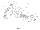
- FIG. 1 is a perspective view of an embodiment of the water bonding fixture of the invention
- FIG. 1A is an alternative embodiment of the water bonding fixture of the Invention
- FIG. 2A illustrates a swimming pool pump assembly including the water bonding fixture according to the present disclosure
- FIG. 2B illustrates the water bonding fixture of the invention in connection with the reservoir of a pump
- FIG. 3 is perspective an alternative embodiment of the water bonding fixture.
- FIG. 4 is a sectional view of the embodiment of FIG. 3 .
- the water bonding fixture of the invention is preferably used in conjunction with pool equipment such as pumps, filters and skimmers and serves to electrically ground the water to prevent unequal electrical potentials between the water and any metallic objects in the pool environment.
- pool equipment such as pumps, filters and skimmers
- the term “pool” encompasses swimming pools, hot tubs, spas and other bathing facilities.
- the water bonding fixture can be used in connection with other water environments that require water bonding, for example, fish tanks, water gardens, and fountains.
- the bonding fixture 100 includes a shaft 120 and a plurality of electrically conductive plates 111 / 112 / 113 in a head portion 110 attached to one end of said shaft 120 .
- Head portion 110 includes at least two, and preferably three or more plates.
- head portion 110 includes three arcuate plates 111 / 112 / 113 having a substantially quadrangular periphery. Plates 111 / 112 / 113 are substantially parallel to each other, or layered, arranged and spaced apart from each other to provide a gap between adjacent plates.
- the gap between the adjacent plates is wide enough to permit the flow of water therethrough and preferably ranges from about 0.015 inches to about 0.25 inches, although distances outside of this range may also be employed whenever appropriate for the purposes described herein.
- Plates 111 / 112 / 113 can be fabricated from an electrically conductive material such as stainless steel, aluminum, brass copper and the like, which is sufficiently corrosion resistant to maintain water bonding effectiveness over the life of the fixture.
- Spacer elements 118 FIG. 2 ) can be disposed between plates 111 / 112 / 113 to maintain the gap spacing.
- a plate surface area in contact with the water is required to be a minimum of nine square inches.
- a single plate with a surface area of nine square inches can be difficult to deploy in small, confined and/or shaped locations.
- a reservoir or pump may have limited interior space in which a large plate could obstruct water flow therein.
- the overall dimensions can be reduced. For example, with three plates each plate can be reduced in size to possess a surface area of three square inches, thereby permitting use of the bonding fixture of the present application in more confined locations.
- Shaft 120 of bonding fixture 100 is generally cylindrical and can include a smooth portion 121 in the vicinity of head portion 110 , a threaded portion 122 , and an end portion 123 .
- a nut 130 e.g., a hex nut
- a washer 131 can be mounted on the shaft 120 between the nut 130 and head portion 110 .
- Seals 115 and 116 can be mounted on the shaft smooth portion 121 between head portion 110 and washer 131 .
- Seals 115 and 116 are preferably fabricated from a resilient polymeric material.
- End portion 123 of the shaft preferably has an axial bore 124 and a screw fastener 140 rotatably mounted to the side of the shaft and which penetrates the shaft.
- Axial bore 124 is adapted to receive a conductive grounding wire which is inserted therein to a distance aligned with screw 140 .
- Screw 140 can be tightened to press down on the wire in bore 124 , thereby fixedly securing the wire and preventing its unintended detachment from bonding fixture 100 .
- Other means for connecting a grounding wire to water bonding fixture 100 are contemplated.
- Water bonding fixture 100 A includes a head portion 150 having multiple conductive plates 141 / 152 / 153 mounted to a threaded shaft 160 .
- Shaft 160 includes a transverse aperture 161 and an axial aperture 162 .
- Water bonding fixture 100 A further includes a nut 165 rotatably mounted on threaded shaft 160 , a washer 166 and a resilient seal 167 .
- a grounding cable 180 having a conductive wire 181 and insulative sheath 182 is shown connected to shaft 160 such that the wire 181 is disposed through the transverse aperture 161 .
- a screw member 170 is engaged in axial aperture 162 and may be tightened onto the wire 181 to fixedly secure wire 181 to prevent inadvertent disconnection.
- grounding wire can be soldered or welded directly to the shaft without any apertures or screws.
- the bonding fixture 100 is shown in conjunction with a reservoir 300 of a swimming pool pump assembly 350 .
- swimming pool pump assembly 350 includes a strainer assembly 300 , a centrifugal pump assembly 320 and a motor 330 .
- Strainer assembly 300 includes a strainer housing or chamber 310 . Chamber 310 is enclosed by wall 311 and during use contains water which is in fluid connection with the swimming pool water.
- Bonding fixture 100 is disposed through an aperture in the wall 311 such that head portion 110 containing plates 111 / 112 / 113 is positioned in chamber 310 and in contact with the water.
- Seal 115 abuts the inner opening of the aperture to prevent water leakage therethrough.
- Seal 116 closes the outer opening of the aperture in wall 311 .
- Seals 115 and 116 have conical portions to seat securely in the respective openings of the aperture in the wall 311 ; other seal configurations are contemplated.
- Bonding fixture 100 A may be employed in a of pump in a manner similar to that of fixture 100 .
- bonding fixture 200 in another embodiment, includes a shaft 220 with a smooth portion 221 and a threaded portion 229 . At the end of smooth portion 221 , bonding fixture 200 includes a head portion 210 .
- Head portion 210 includes a plurality of convex electrically conductive plates 211 / 212 / 213 each having a circular periphery. Plates 211 / 212 / 213 are arranged concentrically in spaced configuration so as to provide gaps between the adjacent plates. The gaps are of sufficient dimensions so as to permit the flow of water therethrough.
- a disk shaped flange 214 is disposed on smooth portion 221 in the concavity formed by the plate 213 .
- the total surface area of the plates 211 / 212 / 213 must be at least nine square inches to comply with building code requirements (although variations are contemplated).
- a single plate would require a diameter of about 3.4 inches.
- the overall diameter of the largest plate 211 can be reduced since multiple plates are employed, each of which contributes to conductive surface a ea for water bonding.
- Bonding fixture 200 can be integrally fabricated as a single piece of metal and can be used in conjunction with washer(s), seal(s) and nut(s) as described above to be mounted to a pool pump, skimmer, filter or other pool equipment. Any of known means (not shown) for attaching a grounding wire to bonding fixture 200 can be used in connection with bonding fixture 200 .
- Bonding fixtures 100 , 100 A and 200 can be used in original equipment or can be after market items for retrofitting into existing equipment.
Abstract
Description
Claims (10)
Priority Applications (2)
| Application Number | Priority Date | Filing Date | Title |
|---|---|---|---|
| US14/566,110 US9431725B2 (en) | 2013-12-13 | 2014-12-10 | Water bonding fixture |
| US15/206,475 US9837733B2 (en) | 2013-12-13 | 2016-07-11 | Water bonding fixture |
Applications Claiming Priority (2)
| Application Number | Priority Date | Filing Date | Title |
|---|---|---|---|
| US201361915611P | 2013-12-13 | 2013-12-13 | |
| US14/566,110 US9431725B2 (en) | 2013-12-13 | 2014-12-10 | Water bonding fixture |
Related Child Applications (1)
| Application Number | Title | Priority Date | Filing Date |
|---|---|---|---|
| US15/206,475 Continuation US9837733B2 (en) | 2013-12-13 | 2016-07-11 | Water bonding fixture |
Publications (2)
| Publication Number | Publication Date |
|---|---|
| US20150167335A1 US20150167335A1 (en) | 2015-06-18 |
| US9431725B2 true US9431725B2 (en) | 2016-08-30 |
Family
ID=53367761
Family Applications (2)
| Application Number | Title | Priority Date | Filing Date |
|---|---|---|---|
| US14/566,110 Active US9431725B2 (en) | 2013-12-13 | 2014-12-10 | Water bonding fixture |
| US15/206,475 Active US9837733B2 (en) | 2013-12-13 | 2016-07-11 | Water bonding fixture |
Family Applications After (1)
| Application Number | Title | Priority Date | Filing Date |
|---|---|---|---|
| US15/206,475 Active US9837733B2 (en) | 2013-12-13 | 2016-07-11 | Water bonding fixture |
Country Status (1)
| Country | Link |
|---|---|
| US (2) | US9431725B2 (en) |
Cited By (1)
| Publication number | Priority date | Publication date | Assignee | Title |
|---|---|---|---|---|
| US20170030099A1 (en) * | 2014-10-30 | 2017-02-02 | Custom Molded Products, Inc. | Water-holding structure bonding kit |
Families Citing this family (2)
| Publication number | Priority date | Publication date | Assignee | Title |
|---|---|---|---|---|
| US20160169422A1 (en) * | 2014-10-30 | 2016-06-16 | Custom Molded Products, Inc. | Water-holding structure pump trap bond retrofit kit |
| US20230108937A1 (en) * | 2021-10-06 | 2023-04-06 | Luis Eduardo Perez | Pool debris collection container |
Citations (47)
| Publication number | Priority date | Publication date | Assignee | Title |
|---|---|---|---|---|
| US3256573A (en) * | 1963-05-08 | 1966-06-21 | Pettibone Mulliken Corp | Sand mulling apparatus |
| US3447233A (en) * | 1966-09-30 | 1969-06-03 | Webb James E | Bonding thermoelectric elements to nonmagnetic refractory metal electrodes |
| US3742985A (en) * | 1967-01-31 | 1973-07-03 | Chemstress Ind Inc | Reinforced pipe |
| US3847722A (en) * | 1972-01-27 | 1974-11-12 | Minnesota Mining & Mfg | Impregnated materials for leak prevention |
| US3847810A (en) * | 1973-05-04 | 1974-11-12 | A Tulumello | Apparatus for separating oil from water and measuring the amount of oil so separated |
| US3967872A (en) * | 1975-04-11 | 1976-07-06 | I-T-E Imperial Corporation | Cradle-type ground lug for conduit |
| US4106832A (en) * | 1977-04-19 | 1978-08-15 | John Joseph Vincent Burns | Electrical grounding clamp |
| US4369266A (en) * | 1979-03-01 | 1983-01-18 | Hoechst Aktiengesellschaft | Concentrated dispersions of fluorinated polymers and process for their preparation |
| US4541413A (en) | 1982-07-09 | 1985-09-17 | Compagnie Francaise De Raffinage | Pump and control unit for a solar heating installation for a water tank, and particularly for a swimming pool |
| US4660909A (en) * | 1985-12-16 | 1987-04-28 | Wilson Daniel P | Remote grounding device for subterranean power systems |
| US5127907A (en) * | 1990-12-06 | 1992-07-07 | Abbott Laboratories | System for eliminating or reducing static electricity in infusion pumping systems |
| US5166626A (en) * | 1990-05-29 | 1992-11-24 | General Electric Company | Electrical capacitance clearanceometer |
| US5270004A (en) * | 1989-10-01 | 1993-12-14 | Minntech Corporation | Cylindrical blood heater/oxygenator |
| US5364281A (en) | 1993-06-01 | 1994-11-15 | Philly D. Harrison | Electrical connector system for grounding member and ground wire |
| US5440235A (en) | 1993-02-01 | 1995-08-08 | Hubbell Incorporated | Submersible pump cable test method |
| US5531883A (en) | 1993-01-23 | 1996-07-02 | Johnson Matthey Public Limited Company | Electrode |
| US5541363A (en) | 1992-11-16 | 1996-07-30 | Thermocraft Industries, Inc. | Wet-environment electrical juncton box and method of making |
| US5545952A (en) | 1993-09-13 | 1996-08-13 | Essef Corporation | Self grounding lamp for special use in an underwater environment |
| US5730149A (en) * | 1993-12-30 | 1998-03-24 | Toto Ltd. | Toilet-bowl-mounted urinalysis unit |
| JPH1189053A (en) * | 1997-09-02 | 1999-03-30 | Sumitomo Wiring Syst Ltd | Grommet |
| US6040522A (en) * | 1998-04-16 | 2000-03-21 | Beggs; William C. | Electrically grounded land surface mounting for electrical equipment |
| US6498291B2 (en) * | 1999-03-11 | 2002-12-24 | James William Brammer | Static electricity eliminator |
| US6497841B1 (en) * | 1997-07-22 | 2002-12-24 | Medtronic, Inc. | Prevention of electrical discharges in polymeric heat exchangers |
| US6501385B1 (en) * | 2001-07-26 | 2002-12-31 | O'quinn Bruce C. | Ground buzzer |
| US6530757B1 (en) | 1999-04-03 | 2003-03-11 | Robert Bosch Gmbh | Housing for a fuel pump driven by an electric motor |
| US6684588B1 (en) | 2002-05-22 | 2004-02-03 | Jesse Jones | Bonded swimming pool ladder anchor socket |
| US6725524B2 (en) | 2001-11-20 | 2004-04-27 | A. O. Smith Corporation | Electric motor bonding lug apparatus |
| US6766573B2 (en) | 2001-11-20 | 2004-07-27 | A. O. Smith Corporation | Electric motor bonding apparatus |
| US7097255B2 (en) * | 2002-01-09 | 2006-08-29 | Oil Sands Underground Mining Corp. | Method and means for processing oil sands while excavating |
| US7168416B2 (en) | 2005-03-23 | 2007-01-30 | Denso International America, Inc. | Multi-point grounding plate for fuel pump module |
| US7485014B2 (en) * | 2006-07-26 | 2009-02-03 | Fci Americas Technology, Inc. | Conductor connection |
| US7670153B2 (en) * | 2007-09-10 | 2010-03-02 | Burndy Technology Llc | Electrical connector |
| US7727387B2 (en) | 2005-09-20 | 2010-06-01 | Goggin Christopher M | Swimming pool skimmer pump assembly |
| US7828530B2 (en) | 2002-10-25 | 2010-11-09 | Financiere Piscine Equipement | Electric motor pump for swimming pool maintenance |
| US7854629B1 (en) | 2010-01-19 | 2010-12-21 | Flowserve Management Company | Power plug system for submersible pump system |
| US20110003331A1 (en) * | 2009-05-02 | 2011-01-06 | Thomas Clayton Pavia | Method for enhanced production of biofuels and other chemicals using biological organisms |
| US7927113B2 (en) | 2006-10-17 | 2011-04-19 | Robert Bosch Gmbh | Pumping assembly with a grounding connection having sharp edges to bite into an insulating layer of the pump housing |
| US7931447B2 (en) | 2006-06-29 | 2011-04-26 | Hayward Industries, Inc. | Drain safety and pump control device |
| US20110094025A1 (en) * | 2007-02-27 | 2011-04-28 | West Paul E | Portable hot tub for land and water |
| US8152538B1 (en) * | 2008-07-30 | 2012-04-10 | Papageorge Timothy A | Fluid bonding fitting and assembly and system incorporating the fitting, and method of use |
| US8188477B2 (en) * | 2008-11-21 | 2012-05-29 | Semiconductor Energy Laboratory Co., Ltd. | Semiconductor device and manufacturing method thereof |
| US8708723B2 (en) * | 2009-08-31 | 2014-04-29 | Pfaudler-Werke Gmbh | Electrical connection between conductive elements |
| US8748748B2 (en) * | 2011-03-01 | 2014-06-10 | Kirkhill-Ta Co. | Clamp assembly and conductive cushion with molded-in grounding foil |
| US8747126B2 (en) * | 2011-10-11 | 2014-06-10 | The United States Of America As Represented By The Secretary Of The Navy | Universal ground adapter for marine cables |
| US20140163664A1 (en) * | 2006-11-21 | 2014-06-12 | David S. Goldsmith | Integrated system for the ballistic and nonballistic infixion and retrieval of implants with or without drug targeting |
| US8899998B2 (en) * | 2012-01-24 | 2014-12-02 | Thomas & Betts International, Llc | Revolving grounding lug |
| US8906300B2 (en) * | 2011-08-11 | 2014-12-09 | The University Of Kentucky Research Foundation | Even perfusion pump-integrated blood oxygenator |
-
2014
- 2014-12-10 US US14/566,110 patent/US9431725B2/en active Active
-
2016
- 2016-07-11 US US15/206,475 patent/US9837733B2/en active Active
Patent Citations (48)
| Publication number | Priority date | Publication date | Assignee | Title |
|---|---|---|---|---|
| US3256573A (en) * | 1963-05-08 | 1966-06-21 | Pettibone Mulliken Corp | Sand mulling apparatus |
| US3447233A (en) * | 1966-09-30 | 1969-06-03 | Webb James E | Bonding thermoelectric elements to nonmagnetic refractory metal electrodes |
| US3742985A (en) * | 1967-01-31 | 1973-07-03 | Chemstress Ind Inc | Reinforced pipe |
| US3847722A (en) * | 1972-01-27 | 1974-11-12 | Minnesota Mining & Mfg | Impregnated materials for leak prevention |
| US3847810A (en) * | 1973-05-04 | 1974-11-12 | A Tulumello | Apparatus for separating oil from water and measuring the amount of oil so separated |
| US3967872A (en) * | 1975-04-11 | 1976-07-06 | I-T-E Imperial Corporation | Cradle-type ground lug for conduit |
| US4106832A (en) * | 1977-04-19 | 1978-08-15 | John Joseph Vincent Burns | Electrical grounding clamp |
| US4369266A (en) * | 1979-03-01 | 1983-01-18 | Hoechst Aktiengesellschaft | Concentrated dispersions of fluorinated polymers and process for their preparation |
| US4541413A (en) | 1982-07-09 | 1985-09-17 | Compagnie Francaise De Raffinage | Pump and control unit for a solar heating installation for a water tank, and particularly for a swimming pool |
| US4660909A (en) * | 1985-12-16 | 1987-04-28 | Wilson Daniel P | Remote grounding device for subterranean power systems |
| US5270004A (en) * | 1989-10-01 | 1993-12-14 | Minntech Corporation | Cylindrical blood heater/oxygenator |
| US5166626A (en) * | 1990-05-29 | 1992-11-24 | General Electric Company | Electrical capacitance clearanceometer |
| US5127907A (en) * | 1990-12-06 | 1992-07-07 | Abbott Laboratories | System for eliminating or reducing static electricity in infusion pumping systems |
| US5541363A (en) | 1992-11-16 | 1996-07-30 | Thermocraft Industries, Inc. | Wet-environment electrical juncton box and method of making |
| US5531883A (en) | 1993-01-23 | 1996-07-02 | Johnson Matthey Public Limited Company | Electrode |
| US5440235A (en) | 1993-02-01 | 1995-08-08 | Hubbell Incorporated | Submersible pump cable test method |
| US5460532A (en) | 1993-06-01 | 1995-10-24 | Philly D. Harrison | Electrical connector system for grounding member and ground wire |
| US5364281A (en) | 1993-06-01 | 1994-11-15 | Philly D. Harrison | Electrical connector system for grounding member and ground wire |
| US5545952A (en) | 1993-09-13 | 1996-08-13 | Essef Corporation | Self grounding lamp for special use in an underwater environment |
| US5730149A (en) * | 1993-12-30 | 1998-03-24 | Toto Ltd. | Toilet-bowl-mounted urinalysis unit |
| US6497841B1 (en) * | 1997-07-22 | 2002-12-24 | Medtronic, Inc. | Prevention of electrical discharges in polymeric heat exchangers |
| JPH1189053A (en) * | 1997-09-02 | 1999-03-30 | Sumitomo Wiring Syst Ltd | Grommet |
| US6040522A (en) * | 1998-04-16 | 2000-03-21 | Beggs; William C. | Electrically grounded land surface mounting for electrical equipment |
| US6498291B2 (en) * | 1999-03-11 | 2002-12-24 | James William Brammer | Static electricity eliminator |
| US6530757B1 (en) | 1999-04-03 | 2003-03-11 | Robert Bosch Gmbh | Housing for a fuel pump driven by an electric motor |
| US6501385B1 (en) * | 2001-07-26 | 2002-12-31 | O'quinn Bruce C. | Ground buzzer |
| US6725524B2 (en) | 2001-11-20 | 2004-04-27 | A. O. Smith Corporation | Electric motor bonding lug apparatus |
| US6766573B2 (en) | 2001-11-20 | 2004-07-27 | A. O. Smith Corporation | Electric motor bonding apparatus |
| US7097255B2 (en) * | 2002-01-09 | 2006-08-29 | Oil Sands Underground Mining Corp. | Method and means for processing oil sands while excavating |
| US6684588B1 (en) | 2002-05-22 | 2004-02-03 | Jesse Jones | Bonded swimming pool ladder anchor socket |
| US7828530B2 (en) | 2002-10-25 | 2010-11-09 | Financiere Piscine Equipement | Electric motor pump for swimming pool maintenance |
| US7168416B2 (en) | 2005-03-23 | 2007-01-30 | Denso International America, Inc. | Multi-point grounding plate for fuel pump module |
| US7727387B2 (en) | 2005-09-20 | 2010-06-01 | Goggin Christopher M | Swimming pool skimmer pump assembly |
| US7931447B2 (en) | 2006-06-29 | 2011-04-26 | Hayward Industries, Inc. | Drain safety and pump control device |
| US7485014B2 (en) * | 2006-07-26 | 2009-02-03 | Fci Americas Technology, Inc. | Conductor connection |
| US7927113B2 (en) | 2006-10-17 | 2011-04-19 | Robert Bosch Gmbh | Pumping assembly with a grounding connection having sharp edges to bite into an insulating layer of the pump housing |
| US20140163664A1 (en) * | 2006-11-21 | 2014-06-12 | David S. Goldsmith | Integrated system for the ballistic and nonballistic infixion and retrieval of implants with or without drug targeting |
| US20110094025A1 (en) * | 2007-02-27 | 2011-04-28 | West Paul E | Portable hot tub for land and water |
| US7670153B2 (en) * | 2007-09-10 | 2010-03-02 | Burndy Technology Llc | Electrical connector |
| US8152538B1 (en) * | 2008-07-30 | 2012-04-10 | Papageorge Timothy A | Fluid bonding fitting and assembly and system incorporating the fitting, and method of use |
| US8188477B2 (en) * | 2008-11-21 | 2012-05-29 | Semiconductor Energy Laboratory Co., Ltd. | Semiconductor device and manufacturing method thereof |
| US20110003331A1 (en) * | 2009-05-02 | 2011-01-06 | Thomas Clayton Pavia | Method for enhanced production of biofuels and other chemicals using biological organisms |
| US8708723B2 (en) * | 2009-08-31 | 2014-04-29 | Pfaudler-Werke Gmbh | Electrical connection between conductive elements |
| US7854629B1 (en) | 2010-01-19 | 2010-12-21 | Flowserve Management Company | Power plug system for submersible pump system |
| US8748748B2 (en) * | 2011-03-01 | 2014-06-10 | Kirkhill-Ta Co. | Clamp assembly and conductive cushion with molded-in grounding foil |
| US8906300B2 (en) * | 2011-08-11 | 2014-12-09 | The University Of Kentucky Research Foundation | Even perfusion pump-integrated blood oxygenator |
| US8747126B2 (en) * | 2011-10-11 | 2014-06-10 | The United States Of America As Represented By The Secretary Of The Navy | Universal ground adapter for marine cables |
| US8899998B2 (en) * | 2012-01-24 | 2014-12-02 | Thomas & Betts International, Llc | Revolving grounding lug |
Cited By (2)
| Publication number | Priority date | Publication date | Assignee | Title |
|---|---|---|---|---|
| US20170030099A1 (en) * | 2014-10-30 | 2017-02-02 | Custom Molded Products, Inc. | Water-holding structure bonding kit |
| US10837189B2 (en) * | 2014-10-30 | 2020-11-17 | Custom Molded Products, Llc | Water-holding structure bonding kit |
Also Published As
| Publication number | Publication date |
|---|---|
| US9837733B2 (en) | 2017-12-05 |
| US20150167335A1 (en) | 2015-06-18 |
| US20160322717A1 (en) | 2016-11-03 |
Similar Documents
| Publication | Publication Date | Title |
|---|---|---|
| US9837733B2 (en) | Water bonding fixture | |
| US3949213A (en) | Underwater light | |
| US4692563A (en) | Cable gland embodying moisture-proof seal | |
| US9437979B2 (en) | Grounding for electrical connectors | |
| US3966363A (en) | Pumping assembly | |
| EP2420725B1 (en) | A pool light assembly | |
| US10837189B2 (en) | Water-holding structure bonding kit | |
| US9397430B2 (en) | Isolated electrical connection assembly and method | |
| US10418865B2 (en) | Stator seat of motor, and connector waterproof structure thereof | |
| US20120122328A1 (en) | Grounding Contact | |
| US8152538B1 (en) | Fluid bonding fitting and assembly and system incorporating the fitting, and method of use | |
| US20150204096A1 (en) | Universal Motor Mount and Cap | |
| AU2014301381B2 (en) | Fluid-conducting system with cathodic corrosion protection | |
| US9762011B2 (en) | Engine block heater cord set | |
| US6725524B2 (en) | Electric motor bonding lug apparatus | |
| US3058086A (en) | Anode | |
| US20160169422A1 (en) | Water-holding structure pump trap bond retrofit kit | |
| US20160123029A1 (en) | Aboveground pool pump trap bond retrofit kit | |
| AU593613B2 (en) | Cable gland embodying moisture-proof seal | |
| KR101746174B1 (en) | Water treatment apparatus using electrostatic field | |
| CA1272257A (en) | Cable gland embodying moisture-proof seal | |
| AU782783B2 (en) | An underwater light | |
| WO2018082094A1 (en) | Waterproof assembly, housing for assembling with the same and waterproof kit | |
| RU2568970C1 (en) | Water pre-filter | |
| US6766573B2 (en) | Electric motor bonding apparatus |
Legal Events
| Date | Code | Title | Description |
|---|---|---|---|
| AS | Assignment |
Owner name: ASIA CONNECTION LLC, NEW YORK Free format text: ASSIGNMENT OF ASSIGNORS INTEREST;ASSIGNORS:SACCOCCIO, MITCH;BONELLI, JONATHAN;AFSHAR, REZA;REEL/FRAME:034465/0541 Effective date: 20141210 |
|
| STCF | Information on status: patent grant |
Free format text: PATENTED CASE |
|
| MAFP | Maintenance fee payment |
Free format text: PAYMENT OF MAINTENANCE FEE, 4TH YR, SMALL ENTITY (ORIGINAL EVENT CODE: M2551); ENTITY STATUS OF PATENT OWNER: SMALL ENTITY Year of fee payment: 4 |
|
| MAFP | Maintenance fee payment |
Free format text: PAYMENT OF MAINTENANCE FEE, 8TH YR, SMALL ENTITY (ORIGINAL EVENT CODE: M2552); ENTITY STATUS OF PATENT OWNER: SMALL ENTITY Year of fee payment: 8 |