US9433894B2 - Removal of hydrogen sulfide from gas streams - Google Patents
Removal of hydrogen sulfide from gas streams Download PDFInfo
- Publication number
- US9433894B2 US9433894B2 US14/261,550 US201414261550A US9433894B2 US 9433894 B2 US9433894 B2 US 9433894B2 US 201414261550 A US201414261550 A US 201414261550A US 9433894 B2 US9433894 B2 US 9433894B2
- Authority
- US
- United States
- Prior art keywords
- absorber
- stream
- alkali
- gas stream
- carbon dioxide
- Prior art date
- Legal status (The legal status is an assumption and is not a legal conclusion. Google has not performed a legal analysis and makes no representation as to the accuracy of the status listed.)
- Active, expires
Links
Images

Classifications
-
- B—PERFORMING OPERATIONS; TRANSPORTING
- B01—PHYSICAL OR CHEMICAL PROCESSES OR APPARATUS IN GENERAL
- B01D—SEPARATION
- B01D53/00—Separation of gases or vapours; Recovering vapours of volatile solvents from gases; Chemical or biological purification of waste gases, e.g. engine exhaust gases, smoke, fumes, flue gases, aerosols
- B01D53/34—Chemical or biological purification of waste gases
- B01D53/46—Removing components of defined structure
- B01D53/48—Sulfur compounds
- B01D53/52—Hydrogen sulfide
- B01D53/526—Mixtures of hydrogen sulfide and carbon dioxide
-
- B—PERFORMING OPERATIONS; TRANSPORTING
- B01—PHYSICAL OR CHEMICAL PROCESSES OR APPARATUS IN GENERAL
- B01D—SEPARATION
- B01D53/00—Separation of gases or vapours; Recovering vapours of volatile solvents from gases; Chemical or biological purification of waste gases, e.g. engine exhaust gases, smoke, fumes, flue gases, aerosols
- B01D53/34—Chemical or biological purification of waste gases
- B01D53/46—Removing components of defined structure
- B01D53/48—Sulfur compounds
- B01D53/52—Hydrogen sulfide
-
- B—PERFORMING OPERATIONS; TRANSPORTING
- B01—PHYSICAL OR CHEMICAL PROCESSES OR APPARATUS IN GENERAL
- B01D—SEPARATION
- B01D53/00—Separation of gases or vapours; Recovering vapours of volatile solvents from gases; Chemical or biological purification of waste gases, e.g. engine exhaust gases, smoke, fumes, flue gases, aerosols
- B01D53/34—Chemical or biological purification of waste gases
- B01D53/74—General processes for purification of waste gases; Apparatus or devices specially adapted therefor
- B01D53/77—Liquid phase processes
- B01D53/78—Liquid phase processes with gas-liquid contact
-
- C—CHEMISTRY; METALLURGY
- C01—INORGANIC CHEMISTRY
- C01D—COMPOUNDS OF ALKALI METALS, i.e. LITHIUM, SODIUM, POTASSIUM, RUBIDIUM, CAESIUM, OR FRANCIUM
- C01D7/00—Carbonates of sodium, potassium or alkali metals in general
- C01D7/12—Preparation of carbonates from bicarbonates or bicarbonate-containing product
- C01D7/126—Multi-step processes, e.g. from trona to soda ash
-
- B—PERFORMING OPERATIONS; TRANSPORTING
- B01—PHYSICAL OR CHEMICAL PROCESSES OR APPARATUS IN GENERAL
- B01D—SEPARATION
- B01D2251/00—Reactants
- B01D2251/30—Alkali metal compounds
- B01D2251/304—Alkali metal compounds of sodium
-
- B—PERFORMING OPERATIONS; TRANSPORTING
- B01—PHYSICAL OR CHEMICAL PROCESSES OR APPARATUS IN GENERAL
- B01D—SEPARATION
- B01D2251/00—Reactants
- B01D2251/60—Inorganic bases or salts
- B01D2251/606—Carbonates
-
- B—PERFORMING OPERATIONS; TRANSPORTING
- B01—PHYSICAL OR CHEMICAL PROCESSES OR APPARATUS IN GENERAL
- B01D—SEPARATION
- B01D2256/00—Main component in the product gas stream after treatment
- B01D2256/22—Carbon dioxide
Definitions
- the present invention relates to the removal of hydrogen sulfide from a gas stream and more particularly to the selective removal of hydrogen sulfide from a carbon dioxide gas stream in a gas-liquid absorber using two separate aqueous alkali sodium carbonate solutions obtained from a soda ash production facility.
- Na 2 CO 3 Sodium carbonate
- soda ash is an important, high volume chemical produced in the United States and used in the manufacture of glass, chemicals, soaps and detergents, and aluminum, as well as in textile processing, petroleum refining and water treatment, among many other uses.
- soda ash sodium carbonate, Na 2 CO 3
- trona ore naturally-occurring trona ore
- nahcolite ore a secondary source
- the largest known trona ore deposits in the United States are located in the Green River Basin in southeastern Wyoming, mostly in Sweetwater County, Wyo., and are typically about 800 to 3000 feet below ground level.
- Nahcolite ore naturally-occurring sodium bicarbonate, NaHCO 3
- the subterranean deposits of trona ore consist primarily (80-95 wt. %) of sodium sesquicarbonate (Na 2 CO 3 .NaHCO 3 .2H 2 O) and contain lesser amounts of sodium chloride (NaCl), sodium sulfate (Na 2 SO 4 ), organic matter, and insolubles such as clay and shales.
- Trona ore may be recovered from subterranean trona ore deposits, for further processing in surface operations into soda ash or other alkali products, by mechanical mining techniques or by various solution mining methods.
- the Green River trona ore deposits are presently being commercially mined both by mechanical mining and by solution mining processes.
- the Piceance Creek nahcolite ore deposits are being mined by solution mining techniques.
- Soda ash production facilities recovering soda ash from trona ore deposits are operated by a number of different organizations in the Green River region of southeastern Wyoming, including FMC Corporation (the assignee of this patent application), Solvay Chemicals, Inc., Tata Chemicals North America and OCI Wyoming LP.
- Mechanical mining also called dry mining, is carried out underground in the subterranean alkali ore beds by mining crews using complex machinery and includes room-and-pillar and long wall mining methods.
- Mechanical mining methods are relatively costly due to the upfront cost of sinking mine shafts and continuing need for mining manpower and complex mining machinery.
- such mechanical mining methods leave unrecovered a significant fraction of the trona ore in the beds being dry mined, e.g., about 60% unrecovered in room-and-pillar mining and about 30% in longwall mining.
- Solution mining is an alternative mining approach for recovering minerals from subterranean ore deposits.
- Solution mining is sometimes referred to as in situ recovery or in situ leaching.
- Solution mining can be utilized either as an alternative to or as a supplement to mechanical mining, for the economical recovery of subterranean mineral ore values, such as in the recovery of alkali values from trona ore as soda ash.
- Solution mining utilizes conventional well drilling technology and involves injecting water or other aqueous-based mining solvent, via a drilled well hole, into a subterranean deposit of trona ore (or other soluble mineral ore); allowing the mining solvent to dissolve soluble ore; pumping the resulting mining solution (mine water) via a drilled well hole to the surface; and processing the mine water to recover dissolved ore values from the solution as solid products, in the form of sodium carbonate or other related sodium-based chemicals.
- Solution mining methods may also be employed for recovering alkali values from depleted ore deposits that have previously been mechanically mined and abandoned.
- An alkali solution from solution mining of a NaHCO 3 -containing ore deposit such as trona or nahcolite typically contains dissolved sodium carbonate and sodium bicarbonate, as well as dissolved organic and inorganic impurities solubilized from the ore deposit.
- Alkali solutions containing Na 2 CO 3 and NaHCO 3 values may be obtained not only via solution mining of NaHCO 3 -containing subterranean ore deposits but also from surface alkali brine lakes or alkali waste ponds.
- the sodium carbonate values in such alkali solutions are normally recovered as soda ash by various crystallization processes, and the impurities present in the alkali solution are typically removed via a purge stream of crystallizer mother liquor, which is discarded.
- Frint et al. '134 describes the recovery of sodium carbonate values from mining liquor obtained from solution mining of subterranean trona ore deposits, via sequential crystallizations of sodium sesquicarbonate and sodium carbonate decahydrate, the latter then being recrystallized as sodium carbonate monohydrate.
- the Frint '134 patent also contains descriptions of various prior art trona ore solution mining techniques, as well as descriptions of surface processing operations: the “sesquicarbonate” and “monohydrate” soda ash crystallization processes used for recovery of soda ash from dry-mined trona ore. Those disclosures of U.S. Pat. No. 5,262,134 are hereby incorporated by reference into the present specification.
- the present invention provides a method for removing hydrogen sulfide from a CO 2 -containing gas stream from a soda ash production facility in a gas-liquid absorber apparatus by utilizing absorber alkali solution streams that are readily available in existing soda ash production facilities and that, unlike prior art procedures, do not require regeneration.
- hydrogen sulfide is removed from a carbon dioxide gas stream in a soda ash production facility in a method comprising
- the first absorber alkali stream is an aqueous alkali waste stream containing at least 1 wt. % Na 2 CO 3 and solubilized impurities from the soda ash production facility and is contacted with the H 2 S-contaminated carbon dioxide gas stream in the first absorber section of the gas absorption apparatus in an amount sufficient to absorb a substantial amount of the H 2 S from the gas stream to produce a H 2 S-depleted carbon dioxide gas stream and an absorber first effluent stream containing the absorbed H 2 S, and
- the second absorber alkali stream is an aqueous process stream containing at least 1 wt. % Na 2 CO 3 from the soda ash production facility and is contacted with the H 2 S-depleted carbon dioxide gas stream in the second absorber section of the gas absorption apparatus in an amount sufficient to absorb a substantial amount of the residual H 2 S in the H 2 S-depleted carbon dioxide gas stream from the gas stream to produce a purified carbon dioxide gas stream and a second absorber effluent stream containing the absorbed residual H 2 S;
- the first absorber alkali stream is an aqueous alkali waste stream containing at least 1 wt. % Na 2 CO 3 and solubilized impurities from the soda ash production facility and is contacted with the H 2 S-contaminated gas stream in the first absorber section of the gas absorption apparatus in an amount sufficient to absorb a substantial amount of the H 2 S from the gas stream to produce a H 2 S-depleted gas stream and an absorber first effluent stream containing the absorbed H 2 S, and
- the second absorber alkali stream is an aqueous process stream containing at least 1 wt. % Na 2 CO 3 from the soda ash production facility and is contacted with the H 2 S-depleted gas stream in the second absorber section of the gas absorption apparatus in an amount sufficient to absorb a substantial amount of the residual H 2 S in the H 2 S-depleted gas stream from the gas stream to produce a purified gas stream and a second absorber effluent stream containing the absorbed residual H 2 S;
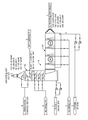
- the FIGURE is a schematic flow diagram illustrating a preferred embodiment of the invention, described in the Example, in which an absorber containing two absorption sections is utilized to remove hydrogen sulfide from a carbon dioxide gas stream in a soda ash production facility, using crystallizer purge liquor as the first absorber section absorber solution and solution mining aqueous liquor as the second absorber section absorber solution.
- the method of the present invention removes hydrogen sulfide that is present as a contaminant in a gas stream, preferably a carbon dioxide gas stream, that is generated in or otherwise available in a soda ash production facility, using a gas-liquid absorption device that utilizes aqueous alkali solution streams that are readily available in a soda ash production facility.
- a unique advantage of the invention is that the spent aqueous absorbent alkali solution streams are not regenerated and do not impose additional economic cost burdens on the soda ash production facility.
- soda ash production facility is broadly defined and should be understood to cover production facilities that recover alkali values as soda ash (sodium carbonate), sodium bicarbonate, or other related sodium mineral products (1) from natural deposits of alkali mineral ores such as trona, nahcolite, wegscheiderite, natron or other NaHCO 3 -containing mineral ores or (2) from natural or man-made alkali lakes containing sodium carbonate (Na 2 CO 3 ), sodium bicarbonate (NaHCO 3 ), or both, as well as other inorganic salts, e.g., sodium chloride, sodium sulfate, and the like.
- alkali mineral recovery operations may involve mechanical mining (including beneficiation of the recovered mineral ore) or solution mining or both, for recovery of alkali values from subterranean ore deposits of the NaHCO 3 -containing mineral ores.
- the method of the present invention involves absorption of hydrogen sulfide from a H 2 S-contaminated gas stream, e.g., a H 2 S-contaminated carbon dioxide gas stream, using a gas-liquid absorption apparatus that comprises two absorption sections or segments, a first section in which the majority of the hydrogen sulfide is removed and a second section in which residual hydrogen sulfide is removed to produce a purified, H 2 S-depleted gas stream that may be vented into the atmosphere.
- a gas-liquid absorption apparatus that comprises two absorption sections or segments, a first section in which the majority of the hydrogen sulfide is removed and a second section in which residual hydrogen sulfide is removed to produce a purified, H 2 S-depleted gas stream that may be vented into the atmosphere.
- the first absorption section utilizes an aqueous alkali solution as the liquid absorbent that is a diverted portion of a waste stream within the soda ash production facility, an aqueous alkali waste stream that has little economic value and that is normally discarded, e.g., into a waste holding pond.
- the aqueous alkali solution waste stream used in the first absorber section is preferably a crystallizer mother liquor purge stream, which functions in the absorber to remove the majority of the hydrogen sulfide from H 2 S-contaminated gas stream.
- the spent absorber effluent withdrawn from the first section of the absorption apparatus is normally directed to the same waste holding pond which would otherwise be the intended destination of the crystallizer liquor purge stream, if the latter were not used in the inventive absorption method.
- the second absorption section utilizes an aqueous alkali solution that is a diverted portion of a valuable process stream used for recovery of its solubilized Na 2 CO 3 values in the soda ash production facility.
- the second absorption section functions as a “polishing step,” to remove a relatively small amount of residual hydrogen sulfide from H 2 S-depleted gas stream.
- the spent absorber effluent withdrawn from the second section of the absorption apparatus therefore has a composition that contains only a small amount of solubilized hydrogen sulfide.
- the spent absorber effluent withdrawn from the second section of the absorption apparatus is not devalued and is readily usable for the same purpose as was originally intended for the source aqueous alkali solution process stream, i.e., recovery of its solubilized Na 2 CO 3 values in the soda ash production facility.
- the hydrogen sulfide absorption method of this invention provides several noteworthy advantages and benefits, in comparison with conventional absorption procedures described in the prior art for removing hydrogen sulfide from H 2 S-containing gas streams.
- the absorber alkali solutions utilized in the present invention are readily available resources within a soda ash production facility, as waste alkali solution streams and as valuable alkali solution process streams. They are not required to be especially prepared for use as absorber liquid absorbent streams for use in the absorption apparatus.
- the method of the present invention nevertheless provides an efficient and highly effective method for removing hydrogen sulfide that may contaminate gas streams in a soda ash facility, particularly H 2 S-contaminated carbon dioxide gas streams generated during the production of soda ash in a soda ash facility, as is described in more detail in the discussion which follows.
- Impurities in aqueous alkali solutions obtained from dissolution of alkali minerals such as trona and nahcolite ores are inevitably present, given that the ores contain various minor components normally considered to be impurities, e.g., sulfate and chloride salts and organic components in the case of trona ore that become solubilized along with sodium carbonate and sodium bicarbonate from the ore's sodium sesquicarbonate component.
- a traditional approach for dealing with such solubilized impurities in aqueous alkali solutions, in crystallization-based soda ash recovery processes that crystallize sodium carbonate monohydrate or sodium carbonate decahydrate, is to purge a portion of the crystallizer mother liquor to prevent the accumulation of impurities in recycled crystallizer mother liquor.
- Decomposition of solubilized sodium bicarbonate to sodium carbonate in the Na 2 CO 3 - and NaHCO 3 -containing alkali solutions is typically carried out in a carbon dioxide stripping unit operation via heating or steam stripping or evaporation.
- the carbon dioxide stripping unit operation results in decomposition of soluble NaHCO 3 in the aqueous alkali solution to form soluble Na 2 CO 3 as well as gaseous byproducts, carbon dioxide and water.
- the gaseous CO 2 and H 2 O byproducts form a carbon dioxide-rich gas stream that exits the carbon dioxide stripping unit operation.
- Hydrogen sulfide is a colorless gas that is well-known for its characteristic “rotten eggs” odor, which is detectable even at very low concentrations, e.g., 1 ppm (volume) H 2 S or less. Hydrogen sulfide at high concentrations, usually associated with accidental releases, is poisonous and can be lethal. At low H 2 S concentrations, there may be adverse health effects from long-term exposure. Although there is no federal ambient air quality standard for hydrogen sulfide, many states in the U.S. have air quality regulations for hydrogen sulfide levels.
- the sulfide content of the sulfide-containing aqueous alkaline solutions treated according to this invention may originate from a variety of different sources.
- Aqueous alkaline solutions obtained from subterranean environments often contain sulfide that originates from microbial activity.
- Sulfides including hydrogen sulfide and sulfide salts, are believed to be formed in subterranean aqueous environments that are in contact with sulfate-containing ores (or petroleum deposits) by the activity of sulfate- or sulfur-reducing microorganisms, particularly anaerobic bacteria, which are naturally present in water and soil. Such aqueous environments are frequently encountered in recovery of alkali minerals.
- solution mining of trona or nahcolite ores with aqueous mining solvents injected into the ore deposits produces aqueous alkali solutions containing Na 2 CO 3 and NaHCO 3 as well as other solubilized impurities, including sulfides.
- Desulfovibrio and Desulfotomaculum bacterial species which convert sulfur or sulfates present in such (largely anaerobic) aqueous environments into sulfides, e.g., hydrogen sulfide at acidic pH levels.
- These gram negative bacteria include Desulfovibrio species like Desulfovibrio desulfuricans and Desulfovibrio salexigens , and Desulfotomaculum species like Desulfotomaculum nigrificans .
- Such bacteria not only require a sulfur source to remain active, but also a carbon source, which is provided by the bicarbonate and carbonate which is present in trona or nahcolite ore deposits.
- Sulfate-reducing bacteria are normally sessile bacteria, i.e., they attach themselves to solid surfaces, as opposed to being free-floating in the aqueous fluid.
- sulfate-reducing bacteria are generally found in combination with slime-forming bacteria, in films consisting of a biopolymer matrix embedded with bacteria. The interior of these biofilms is anaerobic, which is highly conducive to the growth of sulfate-reducing bacteria even if the surrounding environment is aerobic.
- these problematic bacteria are difficult to control with biocides that may be conventionally added to the aqueous medium that is injected into a solution-mined subterranean ore deposit to form an alkali solution for recovery.
- soluble sulfide formation in aqueous alkali solutions is not easily or economically treated via introduction of biocides into the aqueous mining solvent, which is injected in very large volumes into the subterranean ore deposit and tends to remain in the ore deposit cavity for long periods of time before the resultant alkali solution is withdrawn from the cavity.
- Aqueous alkali mining solutions that withdrawn from solution-mined subterranean ore deposits are therefore likely to be contaminated with soluble sulfides, which can become volatilized as gaseous hydrogen sulfide once the withdrawn aqueous alkali mining solution is exposed to the atmosphere or during soda ash processing operations that are carried out on such solutions on the surface.
- a preferred embodiment of the present invention is directed to the treatment of H 2 S-contaminated carbon dioxide-rich gas streams that are formed during the processing of Na 2 CO 3 - and NaHCO 3 -containing aqueous alkali solutions in a soda ash production facility.
- carbon dioxide-rich gas streams are often contaminated by the presence of hydrogen sulfide, in relatively low but significant concentrations, which is volatized from the aqueous alkali solutions being subjected to a carbon dioxide stripping unit operation.
- a primary source of H 2 S-contaminated carbon dioxide-rich gas streams in a soda ash production facility is such gas streams that originate during operation of a carbon dioxide stripping unit operation, usually accomplished or carried out or otherwise effected via heating or steam stripping or evaporation of sulfide-contaminated Na 2 CO 3 - and NaHCO 3 -containing alkali solutions.
- the carbon dioxide stripping unit operation results in decomposition of soluble NaHCO 3 to form soluble Na 2 CO 3 , according to a chemical reaction that may be shown in simplified form as 2NaHCO 3 ⁇ Na 2 CO 3 +CO 2 (g)+H 2 O(g) (1)
- the carbon dioxide stripping unit operation results in decomposition of soluble NaHCO 3 in the aqueous alkali solution to form soluble Na 2 CO 3 as well as gaseous byproducts, carbon dioxide and water. Only a portion of the generated water byproduct remains solubilized in the aqueous alkali solution being stripped.
- the gaseous CO 2 and H 2 O byproducts of the NaHCO 3 decomposition reaction result in formation of a carbon dioxide-rich gas stream that exits the carbon dioxide stripping unit operation.
- the CO 2 -rich gas stream is also humidified by the presence of water.
- H 2 S-contaminated CO 2 -containing gas streams may be generated or originate (1) in evaporative crystallization unit operations carried out to recover sodium carbonate monohydrate in a soda ash facility, (2) in CO 2 absorber operations associated with the production of sodium bicarbonate in a soda ash production facility, (3) in gas streams vented or exhausted from solution mining operations associated with the recovery of alkali values from a NaHCO 3 -containing subterranean ore deposit adjacent to a soda ash production facility, or the like.
- H 2 S-contaminated carbon dioxide gas streams treated in the method of this invention contain significant concentrations of carbon dioxide and such streams may also be referred to as H 2 S-contaminated carbon dioxide-rich (or CO 2 -rich) gas streams in description in the present specification.
- H 2 S-contaminated carbon dioxide gas streams H 2 S-contaminated carbon dioxide-rich gas streams
- H 2 S-contaminated CO 2 -rich gas streams should be understood to refer to gas streams containing a substantial concentration or significant concentration of carbon dioxide.
- a “substantial concentration” or “significant concentration” of carbon dioxide with reference to the carbon dioxide (or CO 2 -rich) gas streams treated according to the present invention is at least about 20 vol. % CO 2 .
- the H 2 S-contaminated carbon dioxide gas streams treated in the method of this invention preferably contain at least about 30 vol. % CO 2 and more preferably contain at least about 50 vol. % CO 2 .
- carbon dioxide concentrations are applicable to carbon dioxide gas streams that have been dehumidified and contain less than about 30 vol. % water vapor.
- carbon dioxide gas streams from carbon stripping unit operations that are carried out via stream stripping will typically be highly humidified, so the carbon dioxide concentration in the humidified gas stream will be diluted by the presence of the significant amounts of water vapor.
- Such water vapor is often routinely removed by condensation or the like, e.g., to less than about 30 vol. % water, before the carbon dioxide gas stream is subjected to further processing in soda ash production facilities.
- the method of the present invention is also applicable to other gas streams that are generated or originated or are otherwise available in a soda ash production facility, where such gas streams do not contain carbon dioxide but that are nevertheless contaminated with H 2 S.
- H 2 S-contaminated gas streams may be generated or originate or otherwise be available or present in a soda ash production facility. Examples include, without limitation, (1) H 2 S-contaminated air or water-containing H 2 S-contaminated gas streams may be generated or originate in the various unit operations carried out in a soda ash production facility or (2) H 2 S-containing air or gas streams, particularly methane-containing gas streams, vented or exhausted from solution mining operations or from mechanical mining operations or during recovery of mineral or petroleum products adjacent to a soda ash production facility.
- the H 2 S-contaminated carbon dioxide gas streams or other H 2 S-contaminated gas streams treated in the method of this invention may contain a range of concentrations of hydrogen sulfide that contaminate the gas stream, from low but significant concentrations to moderate to high H 2 S concentrations.
- Hydrogen sulfide concentrations in the H 2 S-contaminated carbon dioxide gas streams may be significant, e.g., at least 0.1 vol. % H 2 S (1000 ppmv H 2 S) or at least 0.5 vol. % H 2 S (5000 ppmv H 2 S), or even at least 1 vol. % H 2 S (10,000 ppmv H 2 S).
- Lower hydrogen sulfide concentrations can also be problematic in the H 2 S-contaminated carbon dioxide gas streams.
- H 2 S-contaminated carbon dioxide gas streams or in other H 2 S-contaminated gas streams may be effectively treated in the method of this invention and reduced to significantly lower concentrations, such that the treated gas streams may be released into the atmosphere or otherwise utilized in a soda ash production facility, without need for further H 2 S removal treatment steps.
- Hydrogen sulfide removal efficiencies are discussed in more detail below, under Purified Gas Stream—H 2 S Removal Efficiencies.
- the present invention utilizes two aqueous alkali solution streams having distinctly different compositions that make the respective first and second alkali solution streams particularly well suited for their use in the gas-liquid absorption method of this invention, for treating H 2 S-contaminated gas streams in a soda ash production facility.
- the two aqueous alkali solution streams used as liquid absorbents in this invention share several common noteworthy characteristics, in addition to the individually unique characteristics that are discussed further below under the sub-headings, First Absorber Section Alkali Solution and Second Absorber Section Alkali Solution.
- the aqueous solutions that are suitable for use as absorber alkali solution streams according to this invention are characterized by being aqueous alkali solutions that have an alkaline pH value, i.e., a pH value in excess of 7, typically in the range of in excess of pH 7 up to about pH 12, preferably about pH 8 to about pH 11.
- an alkaline pH value i.e., a pH value in excess of 7, typically in the range of in excess of pH 7 up to about pH 12, preferably about pH 8 to about pH 11.
- the aqueous alkali solutions utilized as absorber alkali solution streams in the present invention are aqueous solutions containing (i) dissolved sodium carbonate or (ii) dissolved sodium carbonate along with dissolved sodium bicarbonate.
- the carbonate content, including carbonate with bicarbonate optionally being present, comprises the alkali of the aqueous alkali solutions.
- Such aqueous alkali solutions are further characterized by being readily available in existing soda ash production facilities, at a number of different points or sources within those facilities. Combinations of aqueous alkali solution streams from two or more sources may also be used.
- the solubilized sodium carbonate content of the aqueous alkali solutions utilized as absorber alkali solution streams is appreciable and is preferably significant, so as to promote efficient absorption of hydrogen sulfide from the H 2 S-contaminated gas streams being treated in the present invention.
- the sodium carbonate content of these aqueous alkali solutions contains at least 1 wt. % Na 2 CO 3 , preferably at least about 5 wt. % Na 2 CO 3 and, more preferably, at least about 7 wt. % Na 2 CO 3 and most preferably at least about 10 wt. % Na 2 CO 3 . (These and other weight percentages in this specification applicable to solutions should be understood to mean percentage by weight, based on the total weight of the solution.)
- the aqueous alkali solutions utilized as absorber alkali solution streams in the present invention contain solubilized sodium carbonate and will usually also contain solubilized sodium bicarbonate, the latter typically being present in relatively small concentrations, as compared to the sodium carbonate.
- the sodium bicarbonate concentration in such alkali solution streams is less than the counterpart sodium carbonate concentration.
- the sodium bicarbonate concentration in such alkali solution streams is preferably present in concentrations of less than about 5% NaHCO 3 , more preferably, less than about 4 wt. % NaHCO 3 and, most preferably, less than about 3 wt. % NaHCO 3 .
- Alkali solutions containing high Na 2 CO 3 concentrations i.e., at least about 10 wt. % Na 2 CO 3 up to a saturation concentration of Na 2 CO 3 , are highly preferred, since such high alkali concentrations promote good absorption recovery efficiencies in the absorption of hydrogen sulfide from H 2 S-contaminated carbon dioxide gas streams.
- the inventor While not wishing to be bound by any particular mechanism of action or reaction scheme, the inventor nevertheless believes that the sodium carbonate (Na 2 CO 3 ) content of alkali solutions containing significant or high Na 2 CO 3 concentrations is advantageous for the absorptive removal of H 2 S from the H 2 S-contaminated gas stream into the alkali absorption solution.
- Na 2 CO 3 sodium carbonate
- the sodium carbonate in the alkali absorption solution is believed to react with the absorbed hydrogen sulfide, as follows: Na 2 CO 3 +H 2 S ⁇ NaHCO 3 +NaHS (2)
- Sodium sulfate that is often present in the first absorber section alkali solution as an impurity is also believed to react with absorbed hydrogen sulfide, as follows: Na 2 SO 4 +H 2 S ⁇ NaHSO 4 +NaHS (3)
- the aqueous alkali solutions employed as absorber alkali solutions in this invention preferably have a total alkali (T.A.) content, determined from their dissolved sodium carbonate and sodium bicarbonate contents, of at least about 6 wt. % T.A. More preferably, the aqueous alkali solutions have a total alkali content of at least about 8 wt. %, and, most preferably, at least about 10 wt. % T.A.
- T.A. total alkali
- solubilized salts other than carbonate and bicarbonate e.g., sodium sulfate and other sulfur salts and sodium chloride, are not considered to be components that contribute to the “total alkali” content of an aqueous alkali solution.
- the aqueous alkali solutions utilized as first absorber alkali solution streams, in the first section of the gas-liquid absorption apparatus in the present invention are aqueous alkali solutions in a soda ash facility that normally are considered waste streams.
- Such aqueous alkali solution waste streams typically contain appreciable and preferably significant concentrations of sodium carbonate and lesser concentrations of sodium bicarbonate.
- These aqueous alkali solution waste streams also contain significant concentrations of solubilized impurities, e.g., sodium sulfate (Na 2 SO 4 ) and sodium chloride (NaCl) being most commonly present.
- the aqueous alkali solutions utilized as first absorber alkali solution streams are characterized by containing (i) an appreciable concentration of soluble sodium carbonate, at least 1 wt. % Na 2 CO 3 , preferably at least about 5 wt. % Na 2 CO 3 , more preferably at least about 7 wt. % Na 2 CO 3 , and most preferably at least about 10 wt. % Na 2 CO 3 and (ii) relatively high impurities levels, at concentrations of at least about 1 wt. % impurities, typically at least about 3 wt. % impurities, and sometimes at least about 5 wt. % impurities, or higher.
- aqueous alkali solutions make further processing of such solutions, e.g., to recover their dissolved Na 2 CO 3 and NaHCO 3 values, economically unattractive or unfeasible, so such aqueous alkali solutions are considered waste streams and are typically directed to or collected in holding ponds in the vicinity of the soda ash production facility.
- aqueous alkali solutions waste streams may originate from any of several sources or unit operations within the soda ash production facility, including purge streams from crystallizer unit operations or from waste streams or holding ponds that are associated with mechanical mining or solution mining operations. Combinations of waste streams from two or more sources may also be used.
- Preferred sources of suitable aqueous alkali solutions waste streams include purge streams of aqueous alkali crystallizer mother liquor, which are withdrawn from continuously-operated crystallizers to prevent the level of impurities present in the crystallizer liquor from accumulating to concentrations that interfere with the crystal formation, habit or purity of the sodium carbonate species being crystallized.
- Purge streams of aqueous alkali crystallizer liquor suitable for use as the first absorber aqueous alkali stream in this invention include purge streams from crystallization operations that produce sodium carbonate monohydrate or sodium carbonate decahydrate.
- Purge streams from crystallization operations that produce sodium sesquicarbonate or even sodium bicarbonate may also be used; such sesquicarbonate crystallizer liquors are often characterized by containing relatively high sodium bicarbonate concentrations and therefore are less preferred for use as the first absorber alkali solution stream.
- Purge streams from crystallizer operations vary in composition according to the crystalline species being recovered, as well as the crystallizer operating parameters employed.
- a purge stream from a sodium carbonate monohydrate crystallizer operation may contain, e.g., 19-30 wt. % sodium carbonate, 0.1-0.4 wt. % sodium bicarbonate, up to 2.7 wt. % NaCl, up to 2.4 wt. % Na 2 SO 4 and 100-1500 ppm total organic carbon (TOC).
- a purge stream from a sodium sesquicarbonate crystallizer operation may contain, e.g., 3-25 wt. % sodium carbonate, 1-15 wt.
- a purge stream from a sodium carbonate decahydrate crystallizer operation may contain, e.g., 7-10 wt. % sodium carbonate, 1-4 wt. % sodium bicarbonate, 4-12 wt. % NaCl, 1-3 wt. % Na 2 SO 4 and 100-1500 ppm total organic carbon (TOC).
- TOC total organic carbon
- aqueous alkali solutions containing high levels of impurities suitable for use as the first absorber aqueous alkali solution stream in this invention, include (1) waste or holding ponds employed in conjunction with surface operations for soda ash manufacturing, e.g., alkali-containing ponds that hold soda ash process waste streams, e.g., mother liquor purged from soda ash crystallization operations, or other aqueous waste or byproduct streams from soda ash manufacturing, or (2) waste water streams or waste water ponds containing (a) waste water recovered or pumped from the subterranean location of conventional mechanical mining operations, e.g., dust suppression water or cooling water, or (b) waste water recovered from solution mining operations, both (a) and (b) being referred to herein as mining waste water, e.g., trona mining waste water.
- These aqueous alkali solutions typically contain significant levels of inorganic impurities, e.g., chloride, sulfate, sulfide
- Still another source of aqueous alkali solutions containing high levels of impurities suitable for use as the first absorber aqueous alkali solution stream in this invention, is impure alkaline solutions (brines) that are obtained from naturally-occurring surface brine lakes or surface alkali lakes, e.g., Searles Lake, Owens Lake or Mono Lake in California.
- impure natural alkaline lake brines typically contain significant levels of impurities, e.g., sodium sulfate and sodium chloride, which require additional often-complex processing steps for their removal prior to recovery of sodium carbonate species from such solutions.
- the first absorber effluent stream containing absorbed H 2 S is withdrawn from the first absorber section.
- a portion of the effluent solution from the first absorber section may optionally be recycled to the absorber section, to reduce its alkaline solution demand, i.e., to reduce the volume of absorber solution needed to be introduced to the first absorber section to achieve the desired removal of hydrogen sulfide from the carbon dioxide gas stream in that section.
- the first absorber effluent stream containing absorbed H 2 S that is withdrawn from the first absorber section is not regenerated, to remove its absorbed hydrogen sulfide, e.g., so the regenerated solution may be re-used in the absorption unit operation.
- the impurities levels in the first absorber effluent stream withdrawn from the first absorber section may be higher than those in the first absorber aqueous alkali solution stream introduced into the first absorber section, since absorption of the hydrogen sulfide from the H 2 S-contaminated carbon dioxide gas stream typically results in higher levels of dissolved sulfide in the effluent stream from this absorber section.
- Some dilution of the impurities concentrations in the effluent stream may occur because of condensation of water vapor into the spent absorber effluent solution (such water being condensed from the H 2 S-contaminated carbon dioxide gas stream being treated) in this absorber section.
- the first absorber effluent stream is preferably directed to a waste holding pond for its disposal.
- the waste holding pond may be the same or different from the holding pond into which the purge stream utilized for the first absorber aqueous alkali solution stream would have otherwise been directed.
- the first absorber effluent stream may be directed to an underground cavity into which impure aqueous waste streams are being directed, e.g., a worked out section of a mechanically-mined ore deposit that is safely separated from the working mine operations.
- This disposition of the first absorber effluent stream represents no significant economic cost, since the alkali solution source of the first absorber aqueous alkali solution stream would also have not otherwise been utilized to recover dissolved Na 2 CO 3 and NaHCO 3 values, because of its high impurities content.
- the hydrogen sulfide absorbed into first absorber effluent stream that is directed to a waste alkali holding pond normally does not present a pollution problem, once the spent first absorber effluent stream is added to the waste holding pond that already contains accumulated waste liquor from operations at the soda ash production facility.
- the hydrogen sulfide in the first absorber effluent stream introduced into the waste holding pond does not present a pollution problem from volatilized H 2 S since (i) the concentration of dissolved hydrogen sulfide in the alkali waste solution is relatively low and (ii) a portion of the dissolved sulfide in the holding pond liquor becomes oxidized to sulfate by exposure of the waste pond liquor to air, and this natural reaction is usually catalyzed via the presence of iron and other metallic impurities in the alkaline waste liquor.
- the aqueous alkali solutions utilized as second absorber alkali solution streams, in the second section of the gas-liquid absorber in the present invention, are aqueous alkali solutions in a soda ash facility that are process streams that are subsequently processed to recover their dissolved sodium carbonate values as soda ash.
- These aqueous alkali solutions are typically considered to be valuable or useful process streams, since they are utilized in the soda ash production facility for recovery of their soluble sodium carbonate values, in contrast to the impurities-containing alkali solution waste streams that are employed for use as the first absorber alkali solution streams.
- the aqueous alkali solutions utilized as second absorber alkali solution streams may be obtained from any of several process stream sources that are associated, directly or indirectly, with the recovery of their dissolved sodium carbonate values as soda ash in a soda ash production facility.
- the soda ash production facility may be located at a site where soda ash is recovered from natural mineral ore deposits, by mechanical mining or solution mining or both, or from alkaline lake brine sources.
- the aqueous alkali solutions utilized as second absorber alkali solution streams are characterized by containing (i) an appreciable concentration of soluble sodium carbonate, at least 1 wt. % Na 2 CO 3 , preferably at least about 5 wt. % Na 2 CO 3 , more preferably at least about 7 wt. % Na 2 CO 3 , and most preferably at least about 10 wt. % Na 2 CO 3 and (ii) relatively low impurities levels (in contrast to the impurities-containing solutions employed in the first absorber section.)
- Such aqueous alkali solutions may also contain sodium bicarbonate, in concentrations smaller than those of the soluble sodium carbonate component, as was noted above.
- aqueous alkali solutions as process or feed streams for production and recovery of soda ash, e.g., via crystallization of a desired sodium carbonate species such as sodium carbonate monohydrate, sodium carbonate decahydrate or sodium sesquicarbonate or even sodium bicarbonate (which may be calcined to form an anhydrous soda ash).
- a desired sodium carbonate species such as sodium carbonate monohydrate, sodium carbonate decahydrate or sodium sesquicarbonate or even sodium bicarbonate (which may be calcined to form an anhydrous soda ash).
- aqueous alkali solutions utilized as the second absorber section aqueous alkali solution stream in this invention may be obtained directly from (or indirectly derived from) subterranean alkali mineral ore deposits (i) that contain NaHCO 3 - and Na 2 CO 3 -bearing minerals, e.g., trona (primarily sodium sesquicarbonate, Na 2 CO 3 .NaHCO 3 .2H 2 O), such as the deposits located in the Green River Basin of southwest Wyoming, wegscheiderite (primarily Na 2 CO 3 .3NaHCO 3 ), or (ii) that contain primarily NaHCO 3 , e.g., nahcolite (primarily NaHCO 3 ), such the deposits as located in the Piceance Creek Basin in northwest Colorado. Combinations of these NaHCO 3 - and Na 2 CO 3 -containing minerals may be present in the same deposit or formation.
- NaHCO 3 - and Na 2 CO 3 -bearing minerals e.g., trona (primarily
- the aqueous alkali solutions may be obtained from mechanical mining (from dissolution of dry-mined ore into an aqueous medium) or from solution mining of subterranean ore deposits or from solution mining of previously-mined (mechanical (dry) mining) ore deposits.
- Exemplary and preferred aqueous alkali solutions utilized as second absorber alkali solution streams are (1) aqueous alkali mining solutions that are recovered from solution mining of trona, nahcolite or other NaHCO 3 -containing mineral ores and (2) crystallizer feed stream solutions, used to crystallize sodium carbonate monohydrate, sodium carbonate decahydrate, sodium sesquicarbonate or sodium bicarbonate.
- Preferred solution mining liquors that are employed as absorbent streams in the second absorber section in the present invention are those aqueous alkali mining solutions obtained from solution mining of subterranean trona ore deposits or other NaHCO 3 -containing ore deposits, using solution mining solvents (e.g., water or recycled aqueous streams dilute in dissolved alkali values) and solution mining techniques that are well known in the alkali solution mining art.
- solution mining solvents e.g., water or recycled aqueous streams dilute in dissolved alkali values
- Solution mining liquor streams obtained from solution mining of trona will typically contain about 13 wt. % Na 2 CO 3 and about 4.5 wt. % NaHCO 3 , corresponding to a total alkali content of about 16%.
- Such solution-mined aqueous alkali streams are typically utilized, either alone or in combination with other alkali process streams available within soda ash production facility, as a solution feed to a sodium carbonate crystallization operation.
- the temperature of such subterranean trona deposits typically is within the range of about 68° F. to about 86° F., and the temperature of alkali solution mining streams recovered from solution mining of such deposits will likely be close to these temperatures.
- Aqueous alkali solutions recovered from solution mining of trona ore or other NaHCO 3 -containing ore with water or a dilute aqueous alkali mining solvent are normally not completely saturated, as compared to the theoretical equilibrated saturation concentration obtainable under laboratory conditions.
- aqueous alkali solutions that are essentially equilibrated, saturated solutions (with respect to NaHCO 3 and Na 2 CO 3 ) and that are obtained from the dissolution of sodium sesquicarbonate in trona ore using an aqueous medium such as water at 68° F. in a laboratory environment will contain about 17 wt. % Na 2 CO 3 and about 4 wt.
- % NaHCO 3 corresponding to a total alkali content of about 19.5 wt. % total alkali.
- Small differences in the dissolution solvent temperatures will not significantly change the composition; e.g., the corresponding equilibrated, saturated alkali solution at 86° F. (vs. 68° F. just noted above) will contain about 17 wt. % Na 2 CO 3 and about 4.7 wt. % NaHCO 3 , corresponding to a total alkali content of about 20 wt. % total alkali.
- the aqueous alkali solution utilized as the second absorber section aqueous alkali stream may also be obtained as alkali liquor or solution that is withdrawn from a tailings disposal system associated with a soda ash manufacturing facility, in which dry-mined ore waste solids, i.e., tailings, are introduced as an aqueous slurry into a subterranean cavity and an alkali solution is subsequently withdrawn from the cavity for recovery of soda ash, such as described in U.S. Pat. No. 5,043,149 of Frint et al. (FMC) issued Aug. 27, 1991.
- FMC Frint et al.
- aqueous alkali solution process stream source that may be utilized as second absorber alkali solution streams are soda ash crystallizer feed streams that are used to precipitate and recover sodium carbonate species in a soda ash production facility.
- the crystallizer feed process streams may include the aqueous alkali solution feed streams used to crystallize sodium carbonate monohydrate, sodium carbonate decahydrate or sodium sesquicarbonate.
- the second absorber effluent stream containing absorbed residual H 2 S is withdrawn from the second absorber section. Since the second absorption section functions as a “polishing step,” to remove a relatively small amount of residual hydrogen sulfide from H 2 S-depleted carbon dioxide gas stream, the spent absorber effluent withdrawn from the second section of the absorption apparatus consequently has a composition that contains only a small amount of solubilized hydrogen sulfide.
- the second absorber effluent stream containing absorbed residual H 2 S that is withdrawn from the second absorber section is likewise not regenerated.
- the second absorber effluent stream containing absorbed residual H 2 S is preferably not recycled or otherwise re-used in the absorption unit operation.
- the second absorber effluent stream containing absorbed residual H 2 S still contains valuable sodium carbonate values that may be readily recovered without interference from the relatively small amounts of absorbed hydrogen sulfide that are present.
- Several options are available for further processing of the “spent” second absorber effluent stream, to exploit and ultimately recover its solubilized Na 2 CO 3 values in the soda ash production facility.
- the spent absorber effluent withdrawn from the second section of the absorption apparatus may optionally be combined with an aqueous alkali solution process stream containing Na 2 CO 3 in the soda ash production facility, so that the combined aqueous alkali process stream is processed further downstream to recover its solubilized alkali values in the form of a solid product, via crystallization, evaporation or carbonation, or combinations of these.
- Such solid form products may be soda ash (crystallized, e.g., as sodium carbonate monohydrate, sodium carbonate decahydrate, sodium sesquicarbonate or anhydrous sodium carbonate), sodium bicarbonate (crystallized, e.g., from carbonated Na 2 CO 3 -containing solutions or from NaHCO 3 -containing solutions), or other sodium salt products, e.g., sodium sulfate.
- the Na 2 CO 3 -containing aqueous alkali solution process stream (into which is added the spent absorber effluent stream from the second absorber section) may be the same process stream from which the second absorber aqueous alkali solution stream was originally obtained as a deviated portion of such stream or may be a different process stream within the soda ash production facility.
- the spent absorber effluent withdrawn from the second section of the absorption apparatus may optionally be directed to a subterranean solution mining cavity being worked at the soda ash production facility, since the withdrawn solution mining liquor will ultimately be utilized for recovery of its solubilized sodium carbonate values.
- the absorber apparatus employed in the present invention is a gas-liquid absorber that comprises a first absorber section (or segment) and a second absorption section (or segment).
- the H 2 S-contaminated carbon dioxide gas stream or other H 2 S-contaminated gas stream is sequentially contacted in these absorption sections with a first absorber alkali stream in the first absorber section and with a second absorber alkali stream in the second absorber section, the absorber solutions having been described above.
- the absorber design used to effect the gas-liquid contact in the respective first and second absorber sections may be based on conventional equipment designs utilized for absorbing or scrubbing a gas stream with a liquid stream (the absorber or scrubber solution) to effect an absorptive transfer of a component in the gas stream into the liquid.
- absorber absorption unit
- scrubber scrubbing unit
- a primary objective of the gas-liquid contacting steps in the first absorber section and in the second absorber section is ensuring intimate contact between the H 2 S-containing gas stream and liquid absorber stream, so that the hydrogen sulfide, which is typically present in relatively small or moderate concentrations in the gas stream, e.g., less than 1 vol. % H 2 S, becomes absorbed into the absorption liquid solution to the maximum extent possible.
- the contact between the gas stream and an liquid absorber stream may be accomplished by conventional means used in gas-liquid contacting equipment, e.g., by spraying the liquid absorber stream into the gas stream (as is shown in the preferred embodiment described in the Example and illustrated in the FIGURE), by bubbling the gas stream through the liquid absorber stream, by creating a thin film of liquid absorber solution (e.g., on a packing material) that is contacted with the gas stream, or by other contacting means known to those skilled in the design of gas-liquid contacting equipment.
- conventional means used in gas-liquid contacting equipment e.g., by spraying the liquid absorber stream into the gas stream (as is shown in the preferred embodiment described in the Example and illustrated in the FIGURE), by bubbling the gas stream through the liquid absorber stream, by creating a thin film of liquid absorber solution (e.g., on a packing material) that is contacted with the gas stream, or by other contacting means known to those skilled in the design of gas-liquid contacting equipment.
- the contacting of the gas stream and liquid absorber stream may be co-current, cross-current or counter-current in direction, with the primary objective being to ensure intimate contact between the gas stream and liquid absorber stream, to facilitate and promote absorptive transfer of H 2 S from the gas stream into the absorber solution.
- the two absorber sections are designed in a manner that prevents unwanted transfer of the first absorber section absorption solution, having a high impurities content, into the second absorber section, where the second absorber section absorption solution is relatively free of impurities other than the absorbed H 2 S.
- Such means may be a set of liquor de-entrainment vanes or the like, well known to those skilled in the design of gas-liquid absorption units.
- similar means may be used to prevent the unwanted entrainment of second absorber section absorption solution in the purified, H 2 S-depleted gas stream that exits from the second absorber section after being treated in that section.
- the absorber sections are preferably designed to minimize absorption of carbon dioxide from the CO 2 -rich gas stream into the absorber solution.
- An objective in each absorber section is to maximize absorptive transfer of the hydrogen sulfide in the H 2 S-containing CO 2 -rich gas stream into the absorber solution and to minimize absorptive transfer of carbon dioxide from the H 2 S-containing CO 2 -rich gas stream into the same absorber solution.
- Sodium bicarbonate is desirably minimized in process feed streams in soda ash production facilities, since increased sodium bicarbonate concentrations in Na 2 CO 3 - and NaHCO 3 -containing process streams reduce the amount (quantity) of the desired sodium carbonate species (e.g., sodium carbonate monohydrate, sodium sesquicarbonate, sodium carbonate decahydrate) that can be crystallized from a unit volume of such solutions.
- desired sodium carbonate species e.g., sodium carbonate monohydrate, sodium sesquicarbonate, sodium carbonate decahydrate
- the second absorber section effluent stream is utilized further in the method of this invention, for further processing and recovery of its solubilized Na 2 CO 3 values in the soda ash production facility, so the presence of sodium bicarbonate in such absorber effluent solution is desirably minimized.
- Alkali solutions used in the first absorber section are preferably crystallizer purge liquors, and these solutions contain near-saturation concentrations of some alkali salts, since such solutions are crystallizer mother liquor from crystallization (precipitation) of sodium carbonate monohydrate, sodium sesquicarbonate or sodium carbonate decahydrate.
- first absorber section and second absorber section are each preferably single absorption stage units.
- Single stage extraction is preferred to minimize the absorption of carbon dioxide from the CO 2 -rich gas stream, during the desired absorptive removal of hydrogen sulfide into the absorber solution.
- multistage extraction with either the first absorption section or the second absorption section is feasible, in the present invention.
- a particularly advantageous aspect of the present invention is that the gas-liquid absorption treatment for removal of hydrogen sulfide from H 2 S-contaminated carbon dioxide gas streams or other H 2 S-contaminated gas stream is highly efficient at removing significant amounts of the H 2 S, regardless of the initial concentration or level of hydrogen sulfide contamination in the CO 2 -rich gas stream.
- the method is efficient at removing, via absorption into the aqueous alkali sodium carbonate solutions, hydrogen sulfide concentrations in H 2 S-contaminated gas streams that are relatively high, e.g., at least about 0.1 vol. % H 2 S (1000 ppmv H 2 S) or more or even about 0.5 vol. % H 2 S (5000 ppmv H 2 S) or more, as well as hydrogen sulfide concentrations in H 2 S-contaminated gas streams that are present in more moderate, lower concentrations, e.g., about 500 ppmv H 2 S or more, or about 300 ppmv H 2 S or more, or even about 100 ppmv H 2 S or more.
- the method of this invention is readily capable of reducing the hydrogen sulfide in the treated, purified gas stream to less than 10%, and even less than 5%, of the concentration of hydrogen sulfide in the H 2 S-contaminated gas stream initially introduced into the absorber for treatment.
- the method of this invention can provide treated, purified carbon dioxide gas streams whose hydrogen sulfide concentrations are less than about 1000 ppmv H 2 S, more preferably less than about 500 ppmv H 2 S, still more preferably less than about 100 ppmv H 2 S, and most preferably less than about 30 ppmv H 2 S.
- the treatment efficiencies of the individual first and section sections of the absorber of this invention are likewise impressive, in their respective removals of hydrogen sulfide from the treated carbon dioxide gas streams.
- the first absorber section alkali stream is typically contacted with the H 2 S-contaminated carbon dioxide gas stream in the first section in an amount sufficient to absorb at least 80%, and preferably 90%, of the H 2 S from the H 2 S-contaminated gas stream.
- the second absorber section alkali stream is typically contacted with the H 2 S-depleted gas stream in the second section in an amount sufficient to absorb at least 80%, and preferably 90%, of the H 2 S present in the H 2 S-depleted gas stream entering the second absorber section.
- the treatment method of this invention typically provides residual hydrogen sulfide concentrations in a treated, purified carbon dioxide gas stream or other treated, purified gas stream that are sufficiently low to obviate any need for an additional subsequent “polishing” H 2 S-removal step to achieve further reduction of the residual H 2 S in the gas stream prior to its subsequent disposition after its withdrawal or exit from the second absorber section.
- the treated, purified gas stream may thus be released into the atmosphere, or, in the case of a treated, purified carbon dioxide gas stream, processed to recover its CO 2 content, or reused as a carbon dioxide-rich gas stream for carbonation of a process solution stream downstream in the soda ash production facility.
- the method of the present invention allows a very heavy absorption load to be placed on the first absorber section, because the absorption solution utilized in the second absorption step essentially provides a “free ride”, since the latter requires no subsequent regeneration step and the spent absorption solution is still utilized for its original purpose, i.e., recovery of its solubilized Na 2 CO 3 values.
- this function of the second absorber section solution permits very high H 2 S absorption rates in the first absorption section, using an aqueous alkali waste stream as the first absorber section absorption solution, that provides very high “per unit of absorber solution” absorption rates.
- the “free ride” second absorption step minimizes concern that there might be an “out of specification” break through of H 2 S in the downstream carbon dioxide gas stream that is either exhausted to the atmosphere or utilized as a purified low-H 2 S carbon dioxide gas source, while at the same time not adding a cost burden to the overall absorption operating costs.
- An optional step in the preferred embodiment of this invention involves further processing of the purified carbon dioxide gas stream exiting from the second absorber section and withdrawn from the absorption apparatus, so that a portion (preferably a significant portion, e.g., at least 50%) of its CO 2 -content is either recovered or utilized further downstream, prior to release of the gas stream into the atmosphere.
- This additional step may involve (i) condensation of the CO 2 -rich gas stream to recover carbon dioxide as relatively pure CO 2 , a byproduct that is useful for carbonation of sodium carbonate to make sodium bicarbonate, or (ii) use of the purified, H 2 S-depleted carbon dioxide-rich gas stream in the treatment of other process streams in the soda ash production facility, e.g., in the carbonation of an alkali solution stream containing soluble sodium carbonate to produce or crystallize sodium bicarbonate.
- This Example describes the treatment of a H 2 S-contaminated CO 2 -containing gas stream from a soda ash facility, using an absorption apparatus with two sections, to absorb hydrogen sulfide from the carbon dioxide gas stream prior to release of the gas stream into the atmosphere.
- the Example is best understood by referring also to the FIGURE.
- the H 2 S-contaminated carbon dioxide gas stream is obtained from the CO 2 stripping step in an ELDM (evaporation-lime-decahydrate-monohydrate) soda ash process, which is described in U.S. Pat. No. 5,283,054 of Copenhafer et al.
- the H 2 S-contaminated carbon dioxide gas stream 1 is introduced into an absorption apparatus A, as is shown on the right side of the FIGURE.
- the absorber A comprises two absorption sections, a horizontally-disposed first absorption section A 1 and a vertically-oriented second absorption section A 2 , as is shown in the FIGURE.
- the H 2 S-contaminated carbon dioxide gas stream 1 entering the horizontally-disposed first section A 1 of the absorber apparatus A is contacted with an alkali absorber solution 2 that is introduced into the absorber A 1 via four separate spray nozzles, in a cross-flow orientation with respect to the flow direction of the gas stream, as shown in the FIGURE.
- the alkali absorber solution 2 is introduced via spraying into the first absorber section A 1 at an overall flow rate of 850 gallons per minute, at a temperature of 51° F.
- the alkali absorber solution 2 being introduced into the first section A 1 of the absorber apparatus A is crystallizer purge solution from a soda ash facility.
- This first absorber section alkali solution stream 2 is a diverted portion of an aqueous alkali crystallizer liquor purge stream from a sodium carbonate decahydrate crystallizer.
- This decahydrate crystallizer mother liquor purge serves to prevent the unwanted buildup of impurities in the continuously-operated crystallizer and is normally directed to a waste holding pond for such purge liquor.
- the decahydrate crystallizer mother liquor's high impurities content renders such solution generally impractical for use as a feed stream for further recovery of its sodium carbonate content, so the use of this waste solution stream as the alkali absorber solution being introduced into the first section of the absorber apparatus provides additional economic value for this impurities-containing stream in the operation of the soda ash production facility.
- the aqueous alkali decahydrate crystallizer purge liquor that is used as the first absorber section A 1 alkali absorber solution 2 has the following composition:
- the Na 2 CO 3 content of the first alkali absorber solution 2 makes this solution particularly well suited for the absorptive removal of gaseous hydrogen sulfide from a gas stream.
- the sprayed alkali absorber solution 2 is contacted with the incoming gas stream 1 in the first absorber section A 1 in a cross-flow orientation, as shown in the FIGURE, and the intimate mixing of the liquid spray with the horizontally-flowing flowing gas stream 1 results in selective absorption of a significant portion of the H 2 S content of the gas stream into the alkali absorber liquid, with little concurrent absorption of CO 2 from the CO 2 -rich gas stream.
- the alkali absorber liquid containing absorbed hydrogen sulfide is collected via gravity in the lower portion of the first absorber section A 1 , and this spent alkali absorber effluent liquid is drained as stream 3 and pumped to a waste pond, at a flow rate of 862 gallons per minute.
- the alkali absorber liquid effluent 3 that is collected in the waste pond contains the absorbed hydrogen sulfide, but this hydrogen sulfide in the waste liquor does not present a pollution problem since (i) the concentration of dissolved hydrogen sulfide in the waste liquor is relatively low and (ii) a portion of the dissolved sulfide is continuously converted by oxidation to sulfate, a natural reaction that is catalyzed via the presence of iron and other metallic impurities in the alkali waste liquor.
- the H 2 S-depleted carbon dioxide gas stream that exits the first absorber section within absorber apparatus is routed to the second absorber section A 2 , positioned in a vertical orientation, as is shown in the FIGURE.
- the H 2 S-depleted carbon dioxide gas stream is contacted with a second alkali absorber solution 4 , different in composition and source from the first alkali absorber solution 2 , to effect further absorptive removal of hydrogen sulfide from the H 2 S-depleted carbon dioxide gas stream.
- a second alkali absorber solution 4 different in composition and source from the first alkali absorber solution 2 , to effect further absorptive removal of hydrogen sulfide from the H 2 S-depleted carbon dioxide gas stream.
- the H 2 S-depleted carbon dioxide gas stream entering the vertically-oriented second section of the absorber apparatus is contacted in a countercurrent flow direction with a second alkali absorber solution 4 that is introduced into the absorber section A 2 via three pairs of separate spray nozzles, as shown in the FIGURE.
- the stream of second alkali absorber solution 4 is introduced via spraying into the second absorber section A 2 at an overall flow rate of 400 gallons per minute, at a temperature of 74° F.
- the alkali absorber solution 4 being introduced into the second section A 2 of the absorber apparatus is aqueous solution mining liquor obtained at the soda ash facility.
- This second absorber section alkali solution stream 4 is a diverted portion of aqueous mining solution that is withdrawn from the region of a subterranean solution mining cavity via a withdrawal well.
- This aqueous mining solution is an alkali feed stream that is normally processed in the soda ash production facility to decompose its NaHCO 3 content and then directed to a crystallizer for recovery of its dissolved Na 2 CO 3 values as sodium carbonate monohydrate.
- the aqueous mining solution i.e., solution mining liquor which is also called mine water feed solution, that is used as the second absorber section
- a 2 alkali absorber solution 4 has the following composition:
- this second alkali absorber solution 4 makes the solution particularly well suited for the absorptive removal of residual amounts of gaseous hydrogen sulfide from the H 2 S-depleted carbon dioxide gas stream.
- the sprayed alkali absorber solution 4 is contacted with the incoming H 2 S-depleted carbon dioxide gas stream (from the first absorber section A 1 ) in a countercurrent flow.
- the intimate mixing of the downwardly-directed liquid spray with the upwardly flowing gas stream results in absorption of a significant portion of the residual H 2 S content in the H 2 S-depleted carbon dioxide gas stream into the alkali absorber liquid 4 .
- the upwardly-flowing H 2 S-depleted carbon dioxide gas stream in the second section is then subjected to a second spray treatment with stream 5 , as shown in the FIGURE, before it exits at the top of the absorption apparatus as a purified H 2 S-depleted carbon dioxide gas stream.
- aqueous hot condensate (which is normally generated from evaporation of mine water feed solution as part of a separate process for recovering sodium carbonate in the soda ash facility) is introduced as stream 5 into the second absorber section A 2 , downstream of (i.e., above) the second section A 2 alkali absorber solution 4 spray apparatus, via spraying.
- the aqueous hot condensate stream 5 that is utilized in the latter portion of the second absorber stage A 2 is essentially 100% water and is introduced at a flow rate of 25,000 to 75,000 lb/hr, corresponding to 50-150 gal/min, and is at a temperature of 180° F.
- the absence of impurities or other soluble components in the hot condensate stream 5 minimizes risk of corrosion in this absorber section.
- the aqueous hot condensate stream 5 serves to transfer heat from this hot water stream to the treated gas stream, thus creating a buoyancy effect that facilitates exit of the upwardly-flowing treated gas stream from this section A 2 of the gas absorption apparatus A.
- the spray of hot condensate water 5 also serves to clean the internal surfaces of the second absorber section A 2 (i.e., a packed section for effecting heat transfer) as well as reducing entrained droplets of second section aqueous absorber solution (containing absorbed hydrogen sulfide) that may be carried along with the upwardly flowing gas stream.
- a stream 6 of about 10 gal/min of hot water is also be introduced intermittently into this second absorber section A 2 , to wash the de-entrainment vanes whose purpose is removal of entrained solution droplets from the upwardly-flowing gas stream.
- the spent sprayed alkali absorber solution and hot condensate water are collected via gravity at bottom of the second absorber section A 2 and are drained and removed as stream 7 , at a flow rate of about 450-550 gallons per minute.
- the alkali absorber effluent solution 7 (including the condensate liquor) from the second stage A 2 contains a relatively low concentration of absorbed, dissolved hydrogen sulfide and contains lower levels of other contaminants (e.g., NaCl and Na 2 SO 4 ), due to the diluent effect of the hot condensate water, as compared to the corresponding levels present in the aqueous mining solution used as second alkali absorber solution 4 .
- the concentration of the soluble alkali values in the spent alkali absorber effluent solution 7 collected from the second absorber section is less than that in the incoming absorber solution introduced into the section absorber section A 2 , also due to the diluent effect of the hot condensate water used for gas stream temperature control.
- the spent alkali absorber effluent liquid 7 collected from the second absorber section A 2 is directed to a holding pond, as noted in the FIGURE, and ultimately processed further to recover its dissolved sodium carbonate values in the soda ash facility.
- the spent alkali absorber effluent liquid 7 is not regenerated or otherwise treated to remove its absorbed hydrogen sulfide.
- the spent alkali absorber effluent solution 7 is directed to a holding pond, as noted in the FIGURE, for settling of solids in the effluent.
- the clarified pond water is then injected (not shown in the FIGURE) into the mining cavity from which was obtained the aqueous solution mining liquor that was employed as alkali absorber solution 4 introduced into the second section A 2 of the absorber apparatus A.
- the purified H 2 S-depleted carbon dioxide gas stream 8 exits at the top of absorption apparatus A at an outlet flow rate of about 5,400 ACFM, at a temperature of about 120° F., as shown on the FIGURE.
- the composition of the exiting purified H 2 S-depleted carbon dioxide gas stream 8 is as follows, with the gaseous constituents again being expressed as pounds per hour exiting the absorber:
- the absorption treatment of the H 2 S-contaminated CO 2 -containing gas stream 1 effects a significant reduction in hydrogen sulfide content, from 350 lb/hr inlet to ⁇ 5.3 lb/hr outlet, a reduction of over 98% as compared to the inlet gas composition.
- the concentration of hydrogen sulfide in the exiting purified H 2 S-depleted carbon dioxide gas stream 8 that is withdrawn from the gas absorption apparatus A is about 200 ppm (wt.).
- the exiting purified H 2 S-depleted carbon dioxide gas stream 8 is exhausted into the atmosphere.
- the flow of the aqueous mining solution used as absorber solution 4 in the second section A 2 of the absorber may be adjusted as desired (the solution stream being directed to the first set of spray nozzles in the second section A 2 of the absorption apparatus) to obtain greater or lesser H 2 S removal rates in the second absorber section.
- the spent alkali absorber effluent solution collected from the second absorber section A 2 as stream 7 may alternatively be employed in the soda ash facility in any of the following ways, each of which ultimately results in recovery of its soluble alkali values:
Abstract
Description
2NaHCO3→Na2CO3+CO2(g)+H2O(g) (1)
Na2CO3+H2S→NaHCO3+NaHS (2)
Sodium sulfate that is often present in the first absorber section alkali solution as an impurity is also believed to react with absorbed hydrogen sulfide, as follows:
Na2SO4+H2S→NaHSO4+NaHS (3)
-
- Na2CO3 8 wt. %
-
NaHCO 3 3 wt. % -
NaCl 8 wt. % - Na2SO4 2 wt. %
The combined sodium carbonate and sodium bicarbonate contents (8 wt. % Na2CO3 and 3 wt. % NaHCO3) in the first alkali absorber solution correspond to a total alkali content of 10%. The firstalkali absorber solution 2 has a pH of about 10 and is at a temperature of 51° F. The relatively low temperature of theabsorber solution 2 is advantageous since it improves selectivity of the H2S absorption relative to CO2 absorption from the carbon dioxide-rich gas stream, as well as minimizing corrosion within the first absorber section.
-
- Na2CO3 13 wt. %
-
NaHCO 3 4 wt. % - NaCl<0.5 wt. %
- Na2SO4<0.2 wt. %
The combined sodium carbonate and sodium bicarbonate contents (13 wt. % Na2CO3 and 4 wt. % NaHCO3) in the aqueous mining solution correspond to a total alkali content of 15.5%. The aqueous alkali mining solution has a pH of about 10 and is at a temperature of 74° F.
-
- CO2 25,450 lb/hr
- H2O 460 lb/hr
-
O 2 300 lb/hr - N2 1,150 lb/hr
- H2S<5.3 lb/hr
-
- The spent alkali
absorber effluent solution 7 may be added to the alkali feed solution stream destined for the CO2 stripping unit operation, to decompose its NaHCO3 content. - The spent alkali
absorber effluent solution 7 may be added to the aqueous solution mining liquor stream, a portion of which is diverted and employed as alkali absorber solution in the second absorber section
- The spent alkali
Claims (20)
Priority Applications (1)
| Application Number | Priority Date | Filing Date | Title |
|---|---|---|---|
| US14/261,550 US9433894B2 (en) | 2013-05-09 | 2014-04-25 | Removal of hydrogen sulfide from gas streams |
Applications Claiming Priority (2)
| Application Number | Priority Date | Filing Date | Title |
|---|---|---|---|
| US201361821396P | 2013-05-09 | 2013-05-09 | |
| US14/261,550 US9433894B2 (en) | 2013-05-09 | 2014-04-25 | Removal of hydrogen sulfide from gas streams |
Publications (2)
| Publication Number | Publication Date |
|---|---|
| US20140335001A1 US20140335001A1 (en) | 2014-11-13 |
| US9433894B2 true US9433894B2 (en) | 2016-09-06 |
Family
ID=51864921
Family Applications (1)
| Application Number | Title | Priority Date | Filing Date |
|---|---|---|---|
| US14/261,550 Active 2034-11-22 US9433894B2 (en) | 2013-05-09 | 2014-04-25 | Removal of hydrogen sulfide from gas streams |
Country Status (2)
| Country | Link |
|---|---|
| US (1) | US9433894B2 (en) |
| CN (1) | CN104261407B (en) |
Families Citing this family (1)
| Publication number | Priority date | Publication date | Assignee | Title |
|---|---|---|---|---|
| CN111018075A (en) * | 2019-12-26 | 2020-04-17 | 安徽迪诺环保新材料科技有限公司 | Device and method for removing peculiar smell of titanium sulfate white sewage |
Citations (24)
| Publication number | Priority date | Publication date | Assignee | Title |
|---|---|---|---|---|
| US2388009A (en) | 1943-10-19 | 1945-10-30 | Robert D Pike | Solution mining of trona |
| US3050290A (en) | 1959-10-30 | 1962-08-21 | Fmc Corp | Method of recovering sodium values by solution mining of trona |
| US3119655A (en) | 1961-02-17 | 1964-01-28 | Fmc Corp | Evaporative process for producing soda ash from trona |
| US3184287A (en) | 1961-10-05 | 1965-05-18 | Fmc Corp | Process for the production of soda ash from underground trona deposits |
| US3779602A (en) | 1972-08-07 | 1973-12-18 | Shell Oil Co | Process for solution mining nahcolite |
| US3932583A (en) | 1972-06-19 | 1976-01-13 | Texaco Inc. | Method of removing hydrogen sulfide from a gas containing carbon dioxide |
| US4258019A (en) | 1977-09-29 | 1981-03-24 | Metallgesellschaft Aktiengesellschaft | Process of regenerating alkali carbonate solutions formed by the desulfurization of hot gases |
| US4264104A (en) | 1979-07-16 | 1981-04-28 | Ppg Industries Canada Ltd. | Rubble mining |
| US4285915A (en) * | 1980-04-23 | 1981-08-25 | Intermountain Research And Development Corp. | Recovery of alkali values from trona ore |
| US4636289A (en) * | 1983-05-02 | 1987-01-13 | Allied Corporation | Solution mining of sodium minerals with acids generated by electrodialytic water splitting |
| US4815790A (en) | 1988-05-13 | 1989-03-28 | Natec, Ltd. | Nahcolite solution mining process |
| US4869882A (en) | 1987-12-30 | 1989-09-26 | General Chemical Corporation | Recovery of sodium carbonate values from contaminated dilute soda ash streams |
| US5043149A (en) | 1990-08-29 | 1991-08-27 | Fmc Corporation | Soda ash production |
| US5262134A (en) | 1992-02-21 | 1993-11-16 | Fmc Corporation | Process for producing sodium salts from brines of sodium ores |
| US5283054A (en) | 1993-03-30 | 1994-02-01 | Fmc Corporation | Process for producing sodium salts from brines of sodium ores |
| US5766270A (en) | 1996-05-21 | 1998-06-16 | Tg Soda Ash, Inc. | Solution mining of carbonate/bicarbonate deposits to produce soda ash |
| US5955043A (en) | 1996-08-29 | 1999-09-21 | Tg Soda Ash, Inc. | Production of sodium carbonate from solution mine brine |
| US6228335B1 (en) | 1997-12-10 | 2001-05-08 | Fmc Wyoming Corporation | Process for the production of sodium carbonate crystals |
| US6576206B2 (en) | 2001-06-13 | 2003-06-10 | Fmc Wyoming Corporation | Bicarbonate conversion in a carbonate monohydrate process |
| US6589497B2 (en) | 2001-06-13 | 2003-07-08 | Fmc Wyoming Corporation | Process for preparing soda ash from solution mined bicarbonate brines |
| US6699447B1 (en) | 1999-01-08 | 2004-03-02 | American Soda, Llp | Sodium bicarbonate production from nahcolite |
| US20090200854A1 (en) | 2007-10-19 | 2009-08-13 | Vinegar Harold J | Solution mining and in situ treatment of nahcolite beds |
| US7645435B2 (en) | 2002-01-31 | 2010-01-12 | General Chemical Industrial Products, Inc. | Sodium carbonate recovery from waste streams and impounded sodium carbonate decahydrate deposits |
| US20100066153A1 (en) | 2004-08-17 | 2010-03-18 | Sesqui Mining, Llc | Methods for constructing underground borehole configurations and related solution mining methods |
Family Cites Families (2)
| Publication number | Priority date | Publication date | Assignee | Title |
|---|---|---|---|---|
| AU2008292143B2 (en) * | 2007-08-30 | 2011-12-08 | Shell Internationale Research Maatschappij B.V. | Process for removal of hydrogen sulphide and carbon dioxide from an acid gas stream |
| EP2335804B1 (en) * | 2009-12-04 | 2014-09-10 | Alstom Technology Ltd | A method and a device for cleaning a carbon dioxide rich flue gas |
-
2014
- 2014-04-25 US US14/261,550 patent/US9433894B2/en active Active
- 2014-05-07 CN CN201410190876.7A patent/CN104261407B/en not_active Expired - Fee Related
Patent Citations (26)
| Publication number | Priority date | Publication date | Assignee | Title |
|---|---|---|---|---|
| US2388009A (en) | 1943-10-19 | 1945-10-30 | Robert D Pike | Solution mining of trona |
| US3050290A (en) | 1959-10-30 | 1962-08-21 | Fmc Corp | Method of recovering sodium values by solution mining of trona |
| US3119655A (en) | 1961-02-17 | 1964-01-28 | Fmc Corp | Evaporative process for producing soda ash from trona |
| US3184287A (en) | 1961-10-05 | 1965-05-18 | Fmc Corp | Process for the production of soda ash from underground trona deposits |
| US3932583A (en) | 1972-06-19 | 1976-01-13 | Texaco Inc. | Method of removing hydrogen sulfide from a gas containing carbon dioxide |
| US3934012A (en) | 1972-06-19 | 1976-01-20 | Texaco Inc. | Method of separating hydrogen sulfide from carbon dioxide |
| US3779602A (en) | 1972-08-07 | 1973-12-18 | Shell Oil Co | Process for solution mining nahcolite |
| US4258019A (en) | 1977-09-29 | 1981-03-24 | Metallgesellschaft Aktiengesellschaft | Process of regenerating alkali carbonate solutions formed by the desulfurization of hot gases |
| US4264104A (en) | 1979-07-16 | 1981-04-28 | Ppg Industries Canada Ltd. | Rubble mining |
| US4285915A (en) * | 1980-04-23 | 1981-08-25 | Intermountain Research And Development Corp. | Recovery of alkali values from trona ore |
| US4636289A (en) * | 1983-05-02 | 1987-01-13 | Allied Corporation | Solution mining of sodium minerals with acids generated by electrodialytic water splitting |
| US4869882A (en) | 1987-12-30 | 1989-09-26 | General Chemical Corporation | Recovery of sodium carbonate values from contaminated dilute soda ash streams |
| US4815790A (en) | 1988-05-13 | 1989-03-28 | Natec, Ltd. | Nahcolite solution mining process |
| US5043149A (en) | 1990-08-29 | 1991-08-27 | Fmc Corporation | Soda ash production |
| US5192164A (en) | 1990-08-29 | 1993-03-09 | Fmc Corporation | Soda ash production |
| US5262134A (en) | 1992-02-21 | 1993-11-16 | Fmc Corporation | Process for producing sodium salts from brines of sodium ores |
| US5283054A (en) | 1993-03-30 | 1994-02-01 | Fmc Corporation | Process for producing sodium salts from brines of sodium ores |
| US5766270A (en) | 1996-05-21 | 1998-06-16 | Tg Soda Ash, Inc. | Solution mining of carbonate/bicarbonate deposits to produce soda ash |
| US5955043A (en) | 1996-08-29 | 1999-09-21 | Tg Soda Ash, Inc. | Production of sodium carbonate from solution mine brine |
| US6228335B1 (en) | 1997-12-10 | 2001-05-08 | Fmc Wyoming Corporation | Process for the production of sodium carbonate crystals |
| US6699447B1 (en) | 1999-01-08 | 2004-03-02 | American Soda, Llp | Sodium bicarbonate production from nahcolite |
| US6576206B2 (en) | 2001-06-13 | 2003-06-10 | Fmc Wyoming Corporation | Bicarbonate conversion in a carbonate monohydrate process |
| US6589497B2 (en) | 2001-06-13 | 2003-07-08 | Fmc Wyoming Corporation | Process for preparing soda ash from solution mined bicarbonate brines |
| US7645435B2 (en) | 2002-01-31 | 2010-01-12 | General Chemical Industrial Products, Inc. | Sodium carbonate recovery from waste streams and impounded sodium carbonate decahydrate deposits |
| US20100066153A1 (en) | 2004-08-17 | 2010-03-18 | Sesqui Mining, Llc | Methods for constructing underground borehole configurations and related solution mining methods |
| US20090200854A1 (en) | 2007-10-19 | 2009-08-13 | Vinegar Harold J | Solution mining and in situ treatment of nahcolite beds |
Also Published As
| Publication number | Publication date |
|---|---|
| CN104261407A (en) | 2015-01-07 |
| US20140335001A1 (en) | 2014-11-13 |
| CN104261407B (en) | 2019-07-09 |
Similar Documents
| Publication | Publication Date | Title |
|---|---|---|
| US5955043A (en) | Production of sodium carbonate from solution mine brine | |
| US5283054A (en) | Process for producing sodium salts from brines of sodium ores | |
| US5766270A (en) | Solution mining of carbonate/bicarbonate deposits to produce soda ash | |
| CA2205199C (en) | Method for production of sodium bicarbonate, sodium carbonate and ammonium sulfate from sodium sulfate | |
| US6428759B1 (en) | Production of feed liquors for sodium carbonate crystallization processes | |
| US9079135B2 (en) | Method for removing impurities from flue gas condensate | |
| US10472238B2 (en) | Sulfur dioxide scrubbing system and process for producing potassium products | |
| WO2011138005A1 (en) | Impurities removal from waste solids in the production of soda ash, sodium bicarbonate and/or other derivatives | |
| US8865095B2 (en) | Process for producing sodium bicarbonate | |
| EP2403806A1 (en) | Removal of impurities in the production of crystalline sodium carbonate, bicarbonate, or sulfite | |
| CS277304B6 (en) | Process of microbiological conversion of sulfur-containing noxious substances in waste gases | |
| US20180353899A1 (en) | Process and system for removing sulfur dioxide from flue gas | |
| US8858902B2 (en) | Selective removal of sulfide from aqueous alkali solutions | |
| EP1089939B1 (en) | Method of processing sulfur-containing materials derived from flue gas desulfurization or other sources | |
| US6322767B1 (en) | Process for making sodium carbonate decahydrate from sodium carbonate/bicarbonate liquors | |
| CN103601219B (en) | From sodium alkali desulfurization waste liquor, the method for sodium carbonate and Sodium Thiocyanate 99 is extracted with causticization-acidization | |
| US9433894B2 (en) | Removal of hydrogen sulfide from gas streams | |
| BE1023372B1 (en) | PROCESS FOR PRODUCING SODIUM BICARBONATE | |
| FI67244B (en) | EXHAUST FILLING OF CHLORIDES | |
| ES2409083B2 (en) | PROCEDURE TO PRODUCE SODIUM BICARBONATE. | |
| US2997366A (en) | Gas purification | |
| JP2011162403A (en) | Method for concentrating aqueous calcium chloride solution | |
| US6558646B1 (en) | Method for increasing the lifetime of stretford solution | |
| JPS6121689B2 (en) | ||
| WO2014090947A1 (en) | Process for recovering soda values from underground soda deposits |
Legal Events
| Date | Code | Title | Description |
|---|---|---|---|
| AS | Assignment |
Owner name: FMC WYOMING CORPORATION, PENNSYLVANIA Free format text: ASSIGNMENT OF ASSIGNORS INTEREST;ASSIGNOR:NIEDRINGHAUS, GERALD;REEL/FRAME:033039/0393 Effective date: 20140530 |
|
| AS | Assignment |
Owner name: TRONOX ALKALI WYOMING CORPORATION, CONNECTICUT Free format text: CHANGE OF NAME;ASSIGNOR:FMC WYOMING CORPORATION;REEL/FRAME:035475/0008 Effective date: 20150401 |
|
| AS | Assignment |
Owner name: GOLDMAN SACHS BANK USA, AS COLLATERAL AGENT, NEW Y Free format text: SECURITY INTEREST;ASSIGNOR:TRONOX ALKALI WYOMING CORPORATION;REEL/FRAME:035470/0305 Effective date: 20150401 |
|
| STCF | Information on status: patent grant |
Free format text: PATENTED CASE |
|
| AS | Assignment |
Owner name: TRONOX ALKALI WYOMING CORPORATION, CONNECTICUT Free format text: RELEASE BY SECURED PARTY;ASSIGNOR:GOLDMAN SACHS BANK USA;REEL/FRAME:043524/0193 Effective date: 20170901 |
|
| AS | Assignment |
Owner name: WELLS FARGO BANK, NATIONAL ASSOCIATION, NEW YORK Free format text: SECURITY INTEREST;ASSIGNOR:TRONOX LLC;REEL/FRAME:043993/0340 Effective date: 20170922 |
|
| AS | Assignment |
Owner name: GENESIS ALKALI WYOMING, LP, TEXAS Free format text: ENTITY CONVERSION;ASSIGNOR:TRONOX ALKALI WYOMING CORPORATION;REEL/FRAME:044217/0033 Effective date: 20170901 |
|
| FEPP | Fee payment procedure |
Free format text: SURCHARGE FOR LATE PAYMENT, LARGE ENTITY (ORIGINAL EVENT CODE: M1554); ENTITY STATUS OF PATENT OWNER: LARGE ENTITY |
|
| MAFP | Maintenance fee payment |
Free format text: PAYMENT OF MAINTENANCE FEE, 4TH YEAR, LARGE ENTITY (ORIGINAL EVENT CODE: M1551); ENTITY STATUS OF PATENT OWNER: LARGE ENTITY Year of fee payment: 4 |
|
| AS | Assignment |
Owner name: TRONOX LLC, CONNECTICUT Free format text: RELEASE BY SECURED PARTY;ASSIGNOR:WELLS FARGO BANK, NATIONAL ASSOCIATION;REEL/FRAME:055583/0001 Effective date: 20210311 |