US9449378B2 - System and method for processing stereoscopic vehicle information - Google Patents
System and method for processing stereoscopic vehicle information Download PDFInfo
- Publication number
- US9449378B2 US9449378B2 US13/554,939 US201213554939A US9449378B2 US 9449378 B2 US9449378 B2 US 9449378B2 US 201213554939 A US201213554939 A US 201213554939A US 9449378 B2 US9449378 B2 US 9449378B2
- Authority
- US
- United States
- Prior art keywords
- image
- stereo
- point
- measurement point
- points
- Prior art date
- Legal status (The legal status is an assumption and is not a legal conclusion. Google has not performed a legal analysis and makes no representation as to the accuracy of the status listed.)
- Active, expires
Links
- 238000012545 processing Methods 0.000 title claims abstract description 121
- 238000000034 method Methods 0.000 title claims description 73
- 238000005259 measurement Methods 0.000 claims abstract description 288
- 238000012360 testing method Methods 0.000 claims description 19
- 238000004891 communication Methods 0.000 claims description 17
- 230000008569 process Effects 0.000 claims description 14
- 230000006870 function Effects 0.000 claims description 8
- 239000000725 suspension Substances 0.000 claims description 7
- 238000007726 management method Methods 0.000 description 28
- 239000002131 composite material Substances 0.000 description 26
- 239000013598 vector Substances 0.000 description 20
- 230000008439 repair process Effects 0.000 description 15
- 230000004044 response Effects 0.000 description 15
- 230000003287 optical effect Effects 0.000 description 8
- 238000012546 transfer Methods 0.000 description 8
- 239000011159 matrix material Substances 0.000 description 7
- 238000010586 diagram Methods 0.000 description 6
- 238000003860 storage Methods 0.000 description 6
- 238000004422 calculation algorithm Methods 0.000 description 4
- 238000013507 mapping Methods 0.000 description 4
- 238000003384 imaging method Methods 0.000 description 3
- 238000003909 pattern recognition Methods 0.000 description 3
- 238000000926 separation method Methods 0.000 description 3
- 238000013519 translation Methods 0.000 description 3
- 230000008859 change Effects 0.000 description 2
- 238000004519 manufacturing process Methods 0.000 description 2
- 239000000463 material Substances 0.000 description 2
- 238000000691 measurement method Methods 0.000 description 2
- RAQQRQCODVNJCK-JLHYYAGUSA-N N-[(4-amino-2-methylpyrimidin-5-yl)methyl]-N-[(E)-5-hydroxy-3-(2-hydroxyethyldisulfanyl)pent-2-en-2-yl]formamide Chemical compound C\C(N(Cc1cnc(C)nc1N)C=O)=C(\CCO)SSCCO RAQQRQCODVNJCK-JLHYYAGUSA-N 0.000 description 1
- 238000013475 authorization Methods 0.000 description 1
- 230000005540 biological transmission Effects 0.000 description 1
- 238000004364 calculation method Methods 0.000 description 1
- 230000000052 comparative effect Effects 0.000 description 1
- 238000010276 construction Methods 0.000 description 1
- 230000008602 contraction Effects 0.000 description 1
- 238000007405 data analysis Methods 0.000 description 1
- 238000011161 development Methods 0.000 description 1
- 238000005516 engineering process Methods 0.000 description 1
- 230000007613 environmental effect Effects 0.000 description 1
- 238000007689 inspection Methods 0.000 description 1
- 239000003562 lightweight material Substances 0.000 description 1
- 239000004973 liquid crystal related substance Substances 0.000 description 1
- 238000004321 preservation Methods 0.000 description 1
- 238000003825 pressing Methods 0.000 description 1
- 238000003908 quality control method Methods 0.000 description 1
- 238000011160 research Methods 0.000 description 1
- 230000007723 transport mechanism Effects 0.000 description 1
Images


Classifications
-
- G—PHYSICS
- G06—COMPUTING; CALCULATING OR COUNTING
- G06T—IMAGE DATA PROCESSING OR GENERATION, IN GENERAL
- G06T7/00—Image analysis
- G06T7/50—Depth or shape recovery
- G06T7/55—Depth or shape recovery from multiple images
- G06T7/593—Depth or shape recovery from multiple images from stereo images
-
- G—PHYSICS
- G06—COMPUTING; CALCULATING OR COUNTING
- G06T—IMAGE DATA PROCESSING OR GENERATION, IN GENERAL
- G06T7/00—Image analysis
- G06T7/0002—Inspection of images, e.g. flaw detection
- G06T7/0004—Industrial image inspection
-
- G—PHYSICS
- G06—COMPUTING; CALCULATING OR COUNTING
- G06F—ELECTRIC DIGITAL DATA PROCESSING
- G06F16/00—Information retrieval; Database structures therefor; File system structures therefor
- G06F16/50—Information retrieval; Database structures therefor; File system structures therefor of still image data
-
- G06F17/30244—
-
- G06T7/0075—
-
- H04N13/0203—
-
- H04N13/0246—
-
- H—ELECTRICITY
- H04—ELECTRIC COMMUNICATION TECHNIQUE
- H04N—PICTORIAL COMMUNICATION, e.g. TELEVISION
- H04N13/00—Stereoscopic video systems; Multi-view video systems; Details thereof
- H04N13/20—Image signal generators
- H04N13/204—Image signal generators using stereoscopic image cameras
-
- H—ELECTRICITY
- H04—ELECTRIC COMMUNICATION TECHNIQUE
- H04N—PICTORIAL COMMUNICATION, e.g. TELEVISION
- H04N13/00—Stereoscopic video systems; Multi-view video systems; Details thereof
- H04N13/20—Image signal generators
- H04N13/204—Image signal generators using stereoscopic image cameras
- H04N13/246—Calibration of cameras
-
- G—PHYSICS
- G06—COMPUTING; CALCULATING OR COUNTING
- G06T—IMAGE DATA PROCESSING OR GENERATION, IN GENERAL
- G06T2207/00—Indexing scheme for image analysis or image enhancement
- G06T2207/10—Image acquisition modality
- G06T2207/10004—Still image; Photographic image
- G06T2207/10012—Stereo images
-
- G—PHYSICS
- G06—COMPUTING; CALCULATING OR COUNTING
- G06T—IMAGE DATA PROCESSING OR GENERATION, IN GENERAL
- G06T2207/00—Indexing scheme for image analysis or image enhancement
- G06T2207/20—Special algorithmic details
- G06T2207/20092—Interactive image processing based on input by user
- G06T2207/20101—Interactive definition of point of interest, landmark or seed
Definitions
- a common task in various fields is to determine the location of a point on an object relative to another point on the object or another object.
- the relative locations of parts of an item preferably fall within a specified tolerance.
- the foundation of a building is tracked to determine shifts in location over time.
- a shift in the location of a part determines whether any damage has occurred, and if so, the extent of the damage.
- Stereoscopic imaging or stereoscopy, is used to obtain three-dimensional information about an object based on a pair of two-dimensional images of that object.
- stereoscopic imaging involves obtaining at least two images of an object, taken from slightly different viewpoints, to determine the three-dimensional information.
- coordinate locations of desired measurement points identified in both images can be more accurately determined.
- Photogrammetry is the basis for photogrammetry, which involves producing stereograms or a pair of stereo images of an object in order to determine geometric properties and/or measurement information about the object.
- Photogrammetry is used in various fields, such as manufacturing, architectural surveying, building preservation, and archaeology in order to obtain measurement information for an object of interest.
- a stereoscopic processing system allows easier designation of measurement points in stereo images of an object to obtain more accurate measurements.
- a common task is to determine whether there is damage to a part, including a vehicle's structure, and if so, the extent of that damage. Another task is to document the actual damage for insurance and other purposes. In the course of repairing a vehicle's body work, one or more wheel alignments are regularly performed.
- a system comprising at least one processor for obtaining measurements of an object.
- the system may be used to determine the relative location of a point on the object.
- the system comprises a processing system, a stereo image pair, and an image capture device for simultaneously capturing a first image and a second image of an object.
- the processing system comprises a memory and is configurable to store a stereo image pair comprising first and second images of a particular object.
- the processing system is further configurable to generate a list of stereo image pairs for display, to generate corresponding first and second images of a particular stereo image pair selected from the list for display.
- the processing system is configurable to receive a first user input designating a first measurement point in the corresponding first image, a second user input designating a second measurement point in the corresponding first image, a third user input designating the first measurement point along a selection assist line in the corresponding second image, and a fourth user input designating the second measurement point along another selection assist line in the corresponding second image.
- the processing system is configurable to identify a range of points in the corresponding second image based on the first measurement point designated in the corresponding first image, to generate the selection assist line in the corresponding second image based on the range of points, to identify another range of points in the corresponding second image based on the second measurement point designated in the corresponding first image, and to generate the other selection assist line in the corresponding second image based on the other range of points.
- the processing system is configurable to define a first stereo point that corresponds to the first measurement point designated in the corresponding first and second images and to define a second stereo point that corresponds to the second measurement point designated in the corresponding first and second images.
- the processing system is configurable to calculate a distance between the first stereo point and the second stereo point.
- the measurement points may be located on a test portion of the object where damage or deviation from a preferred location is suspected. In another aspect, the measurement points may be located on a reference portion of the object where it is known or believed that there is no damage or deviation. In yet another aspect, some measurement points may be located on the test portion, while other measurement points may be located on the reference portion. See FIG. 17 .
- a system comprising at least one processor for obtaining measurements from a stereo image pair of an object.
- the system comprises a processing system and a stereo image pair.
- the stereo image pair comprises first and second images of the object.
- the processing system comprises a memory, and is configurable to generate the first image and the second image for display and to receive a first user input designating a first measurement point in the first image and a second user input designating a second measurement point in the first image.
- the processing system is configurable to define a projection vector in the second image based on the first measurement point, to generate a selection assist line in the second image based on the projection vector, to identify another projection vector in the second image based on the second measurement point, to generate another selection assist line in the second image based on the other projection vector, to determine first pixel values adjacent to the first measurement point, to compare the determined first pixel values with other pixel values along the selection assist line to dynamically identify a corresponding first measurement point in the second image with adjacent other pixel values that match the determined first pixel values, to determine second pixel values adjacent to the second measurement point designated in the first image, and to compare the determined second pixel values with second other pixel values along the other selection assist line to dynamically identify a corresponding second measurement point in the second image with adjacent other pixel values that match the determined second pixel values.
- the processing system is configurable to define a first stereo point that corresponds to the first measurement point designated in the first image and identified in the second image and to define a second stereo point that corresponds to the second measurement point designated in the first image and identified in the second image.
- the processing system is configurable to calculate a distance between the first stereo point and the second stereo point.
- the processing system is configurable to display the distance between the first stereo point and the second stereo point.
- a method for obtaining measurements from a stereo image pair of an object.
- the stereo image pair comprises first and second images of the object.
- the method comprises displaying the first image and the second image.
- the method further comprises designating a first measurement point in the first image and designating a second measurement point in the first image.
- the method further comprises identifying a range of points in the second image based on the first measurement point and identifying another range of points in the second image based on the second measurement point.
- the method further comprises generating a selection assist line in the second image based on the range of points and generating another selection assist line in the second image based on the other range of points.
- the method further comprises designating the first measurement point in the second image along the selection assist line and designating the second measurement point in the second image along the other selection assist line.
- the method further comprises defining a first stereo point that corresponds to the first measurement point designated in the first and second images and defining a second stereo point that corresponds to the second measurement point designated in the first and second images.
- the method also comprises calculating a distance between the first stereo point and the second stereo point.
- a method for obtaining measurements from a stereo image of an object using at least one processor.
- the stereo image pair comprises first and second images of the object.
- the method comprises displaying the first image and the second image.
- the method further comprises designating a first measurement point and designating a second measurement point in the first image.
- An embodiment of the method also comprises receiving a user input to designate the first measurement point and receiving another user input to designate the second measurement point.
- the method further comprises identifying a range of points in the second image based on the first measurement point designated in the first image and identifying another range of points in the second image based on the second measurement point designated in the first image.
- the method further comprises generating a selection assist line in the second image based on the range of points and generating another selection assist line in the second image based on the other range of points.
- the method further comprises determining first pixel values adjacent to the first measurement point designated in the first image and determining second pixel values adjacent to the second measurement point designated in the first image.
- the method further comprises comparing the determined first pixel values with other pixel values along the selection assist line to dynamically identify a corresponding first measurement point in the second image with adjacent other pixel values that match the determined first pixel values.
- the method further comprises comparing the determined second pixel values with second other pixel values along the other selection assist line to dynamically identify a corresponding second measurement point in the second image with adjacent second other pixel values that match the determined second pixel values.
- the method further comprises defining a first stereo point that corresponds to the first measurement point designated in the first image and identified in the second image and defining a second stereo point that corresponds to the second measurement point designated in the first image and identified in the second image.
- the method also comprises calculating a distance between the first stereo point and the second stereo point.
- a system comprising modules executable with at least one processor for obtaining measurements of an object.
- the system comprises a processing system, which comprises a memory to store a stereo image pair of the object.
- the stereo image pair comprises first and second images of the object.
- the processing system is configurable to generate the first and second images of the object for display.
- the processing system is configurable to designate a first set of points in a first stereo image pair and to designate a second set of points in a second stereo image pair, wherein the first stereo image pair comprises the first and second images of a portion of the object, and wherein the second stereo image pair comprises other first and second images of an opposite portion of the object. See FIGS. 11 and 18 .
- the processing system is configurable to receive user inputs to designate the first set of points and the second set of points.
- the processing system is configurable to define a reference plane for the set of points in the first stereo image pair and a reference plane for the set of points in the second stereo image pair and to calculate symmetry deviations between the first set of points and the second set of points as a function of the defined reference planes, and wherein the user interface component is configured to generate the symmetry deviations for display.
- one set of points may be located on a reference portion of the object.
- the processing system is further configurable to calculate deviations of points from known reference coordinates as a function of the reference planes.
- a method for obtaining measurements of an object using at least one processor.
- the method comprises storing a stereo image pair in a memory.
- the stereo image pair comprises first and second images of the object.
- the method further comprises displaying first and second images of the object.
- the method further comprises receiving a first set of user inputs designating a first set of points in a first stereo image pair and receiving a second set of user inputs designating a second set of points in a second stereo image pair, wherein the first stereo image pair comprises the first and second images of a portion of the object, and wherein the second stereo image pair comprises other first and second images of an opposite portion of the object.
- the method further comprises defining a reference plane between the first set of points in the first stereo image pair and the second set of points in the second stereo image pair.
- the reference plane may be a central reference plane.
- the method further comprises calculating symmetry deviations between the first set of points and the second set of points as a function of the defined reference plane.
- the method also comprises displaying the symmetry deviations.
- FIG. 1 is a block diagram of a stereoscopic measurement system in accordance with an aspect of the present invention.
- FIGS. 2A and 2B are perspective views of a stereo image capture device according to an aspect of the stereoscopic measurement system.
- FIG. 3A is a block diagram of a stereoscopic measurement application according to one aspect of the stereoscopic measurement system.
- FIGS. 3B-3D are image views of a camera sectioned for intrinsic camera calibration.
- FIG. 3E is an image of a vehicle with a central reference plane between selected points.
- FIG. 3F is a geometric model for determining symmetry between selected points on an image.
- FIGS. 4A-4F are screen views of image management forms.
- FIG. 5A is a geometric mapping model for a pinhole camera.
- FIG. 5B is a three-dimensional model of the coordinate system for a pinhole camera.
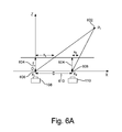
- FIG. 6A-6B are triangulation models for determining the location of a point in a coordinates system of an image capture device.
- FIGS. 7A-7D are illustrations of an overlay process for creating a composite stereo image pair from two stereo image pairs.
- FIG. 8 is a flow chart illustrating a stereo image acquisition method according to one aspect of the stereoscopic measurement system.
- FIG. 9 is a flow chart illustrating a point measurement method within a stereo image pair according to one aspect of the stereoscopic measurement system.
- FIG. 10 is a flow chart illustrating a method for calculating and reporting measurements between designated measurement points in a stereo image pair according to one aspect of the stereoscopic measurement system.
- FIG. 11 is an illustration of the calibration pattern in the image of the object.
- FIGS. 12-15 are illustrations of some reference coordinate planes.
- FIG. 16 is an illustration of a wheel and suspension system of a vehicle.
- FIG. 17 is an illustration of measurement points on a vehicle.
- FIG. 18 is an illustration of measurements points on the door frames of a vehicle.
- FIG. 19 is a diagram of reference planes.
- FIG. 20 is a diagram of reference planes.
- aspects of the stereoscopic measurement system and method described herein allow a user to generate stereo images of an object, to designate points within the stereo images of the object, and to obtain precision measurements in reference to the designated points.
- One aspect of the system is the provision of a portable capture device that allows a user to capture stereo images of objects at remote locations.
- the portable capture device transmits stereo images to a processing system to display the stereo images and to determine precision measurements between designated points within the stereo images.
- the system can be deployed in various environments, and is more portable and cost effective than conventional measuring systems.
- FIG. 1 depicts an exemplary aspect of a stereoscopic measurement system 100 .
- the stereoscopic measurement system 100 enables a user 102 to capture stereo images of an object 104 with a stereo image capture device 106 .
- the stereo image capture device 106 comprises a left camera 108 and a right camera 110 .
- the left camera 108 and right camera 110 are, for example, digital pinhole cameras located on opposing ends of a frame member 112 .
- a monitor 114 is centrally disposed between the left camera 108 and the right camera 110 on the frame member 112 .
- the monitor 114 is configured to display a left image 116 captured by the left camera 108 and a right image 118 captured by the right camera 110 .
- a single monitor 114 is depicted in FIG. 1 , it is contemplated that separate monitors, such as depicted in FIGS. 2A and 2B , can be used to display the left image 116 and the right image 118 .
- the stereo image capture device 106 is a portable hand-held apparatus that comprises a backbone 202 that is sufficiently rigid to limit flexing.
- the backbone 202 can be constructed from a lightweight material, such as plastic or another suitable material.
- a left pod 204 is affixed to the left end of the backbone 202 and a right pod 206 is affixed to the right end of the backbone 202 .
- the left pod 204 is configured to house the left camera 108
- the right pod 206 is configured to house the right camera 110 .
- a hub 208 is located at the center of the backbone 202 and houses a power source (not shown) for powering the left and right cameras 108 , 110 .
- the hub 208 comprises a battery compartment (not shown) that receives a battery.
- the hub 208 comprises power input terminals (not shown) configured to connect with a power cord that is connected to a power outlet.
- the hub 208 comprises a left monitor 210 and a right monitor 212 .
- the left monitor 210 and the right monitor 212 are, for example, liquid crystal display (LCD) monitors.
- the left monitor 210 is connected to the left camera 108 and displays the left image 116 .
- the right monitor 212 is connected to the right camera 110 and displays the right image 118 of the object 104 .
- the user 102 maneuvers the stereo image capture device 106 to display left and right images 116 , 118 of a desired portion of the object 104 via the left and right monitors 210 , 212 .
- the central location of the monitors 210 , 212 allows the user 102 to conveniently determine a common field of view for the left and right cameras 108 , 110 .
- a left handle 214 is located to the left of the hub 208 and a right handle 216 is located to the right of the hub 208 .
- the handles 214 , 216 of the image capture device 106 can be located in a different position or locations.
- the user 102 holds the image capture device 106 via the left handle 214 and right handle 216 .
- the left handle 214 comprises a switch 218 that controls the electronic shutters of the left camera 108 and the right camera 110 .
- the switch 218 is wired to the left and right cameras 108 , 110 to ensure that the corresponding left and right images 116 , 118 are captured simultaneously.
- the user 102 actuates or toggles the switch 218 to capture the left and right images 116 , 118 .
- the left camera 108 and right camera 110 are configured to transfer images and image data to the hub 208 via universal serial bus (“USB”) cables.
- USB universal serial bus
- the left camera 108 is wired to a communication port 220 by a USB cable
- the right camera 110 is wired to the communication port 220 by another USB cable.
- the hub 208 is mounted on a swivel such that it can be rotated independently from the left camera 108 and the right camera 110 .
- the user 102 can view the monitors 210 , 212 regardless of the orientation of the right and left cameras 108 , 110 .
- lamps 222 , 224 are located next to the left and right cameras 108 , 110 .
- the purpose of the lamps 222 , 224 is to illuminate the object 104 during capture of the left and right images 116 , 118 .
- the lamps 222 , 224 are configured to turn on, or flash, when the switch 218 is toggled.
- the lamps 222 , 224 are configured to turn on when a separate switch (not shown) is toggled.
- the image capture device 106 is configured to transfer the left image 116 and the right image 118 to a processing system 120 for processing via a wired or wireless communication link.
- the image capture device 106 is configured to wirelessly transfer images to the processing system 120 in response to the user 102 actuating a transmit switch (not shown) on the image capture device 106 .
- a wireless transmitter 122 is connected to the image capture device 106 via the communication port 220 .
- the transmitter 122 transmits a signal 124 comprising image data representative of the left and right images 116 , 118 .
- the transmitter 122 is depicted external to the image capture device 106 , it is contemplated that the transmitter 122 may be integrated into the image capture device 106 .
- a wireless receiver 126 is connected to the processing system 120 and receives the signal 124 from the transmitter 122 .
- the transmitter 122 and corresponding receiver 126 may utilize a Gigabit Ethernet link, IEEE 802.11 link, Ultra-Wide Band (UWB) link, or any other suitable wireless communication link.
- the wireless transmitter 122 and wireless receiver are optional in some embodiments.
- the image capture device 106 transfers the left image 116 and the right image 118 from the image capture device 106 to the processing system 120 via a wired connection 128 in response to the user 102 actuating the transmit switch (not shown).
- the processing system 120 automatically downloads images from the capture device 106 in response to detecting the wired connection 128 between the image capture device 106 and the processing system 120 .
- the wired connection 128 can be a USB connection, a FireWire connection, or any other suitable wired connection.
- the processing system 120 comprises a stereoscopic measurement application (“measurement application”) 130 .
- the measurement application 130 comprises executable modules or instructions that enable the processing system 120 to process image data, display stereo images, and to obtain precise measurement data for designated points within stereo images.
- the processing system 120 is a remote computer, such as a laptop computer or a personal computer station.
- the processing system 120 is a server computer.
- a user interface (UI) 132 enables the user 102 to select images and/or to issue processing commands.
- Processing commands comprise, for example, commands to initiate image data acquisition from the image capture device 106 and/or commands to initiate image data analysis.
- the UI 132 comprises a display 134 , such as a computer monitor, for viewing image data and an input device 136 , such as a keyboard or a pointing device (e.g., mouse, trackball, pen, touch pad, or other device), for allowing the user 102 to interact with the image data.
- the UI 132 is configured to display one or more input forms via the display 134 .
- the input forms enable the user 102 to select image data for viewing and/or editing.
- the input forms also enable the user 102 to designate points within stereo images and to display measurement information for the designated points.
- the processing system 120 comprises a memory 138 for storing stereo image data for a particular object 104 , including processed and/or raw image data.
- the memory 138 comprises one or more files 140 each comprising processed and/or unprocessed image data for the object 104 .
- the stereoscopic measurement system 100 compares defined stereo points based on user-designated points within stereo images of the object 104 with known reference stereo points for that object. By comparing defined stereo points of stereo images of an object 104 , such as a damaged vehicle to corresponding reference stereo points of an undamaged vehicle, the measurement system 100 determines one or more measurements between the defined stereo points and the reference stereo points to quantify an amount of damage to the vehicle.
- the object is damaged, and the processing system is configurable to measure points on a second object, wherein the second object corresponds to the object and is undamaged.
- the damaged object is a part of the vehicle, and the second object is a corresponding part of the vehicle.
- the damaged object may be a door frame on the driver's side of a vehicle, while the second object may be the corresponding door frame on the passenger side.
- the damaged object is a part of a vehicle, and the second object is a corresponding part on an undamaged vehicle.
- the processing system is further configurable to designate at least three measurement points in a stereo image pair of the object and at least three measurement points in another stereo image pair of the second object.
- a method for recording information regarding a vehicle comprises providing a processing system with a memory.
- a user designates a first and second measurement point in a first image of a stereo image pair.
- the method further comprises designating or identifying the corresponding first and second measurement points in a second image of the stereo image pair.
- the method also comprises determining a first and a second stereo point corresponding to the first and second measurement points, respectively, and calculating a distance between the first and the second stereo points.
- the method comprises storing the measurement points, the stereo points, the calculated distance, and the stereo image pair in memory, and associating each of the points and the calculated distance with the stereo image pair.
- the stereoscopic measurement system 100 determines the wheel alignment of a vehicle. Measurement points designated and identified within stereo image pairs of portions of a vehicle are used to indicate the alignment.
- the system 100 is operable to determine the alignment of and/or damage to various vehicle subsystems, including a wheel and suspension subsystem, an engine cradle, a lower control arm, a unibody structure, lower rails, a rear toe, a rear thrust angle, and rear cradle.
- FIG. 16 is an illustration of some parts of a wheel and suspension subsystem.
- a stereoscopic image pair of the undamaged side of the vehicle is taken and stored.
- a stereoscopic image pair of an undamaged portion of another vehicle of the same model is taken and stored.
- the measurements of the reference points (spindle, rotor, knuckle, and strut, for example) of the undamaged side of the vehicle (or the undamaged portion of the other vehicle) are used for comparison with the damaged side reference points, and repair is performed so that the damaged side reference points match the undamaged side reference points.
- the designated points may be located on specific portions of the wheel and suspension subsystem, including the vehicle's rocker panel, spindle, rotor, knuckle, and strut.
- a vehicle body shop performing the collision repair transfers a vehicle multiple times to and from another facility that determines wheel alignment. The body shop uses the system 100 to determine wheel alignment during the course of repair, thus minimizing multiple transfers to the alignment facility.
- the stereoscopic measurement system 100 detects a change in an object 104 that occurs over a period of time.
- the stereoscopic measurement system 100 is used to calculate a current distance between two user-designated points in the stereo images of the exterior of a building.
- One of the designated points is, for example, a reference point such as a ground elevation benchmark that remains substantially constant over time.
- the other designated point is, for example, a target point on the exterior of the building.
- the stereoscopic measurement system 100 is used to calculate the distance between the same reference point and the same target point of the building. Accordingly, a change in the calculated distance between the reference point and target point indicates, for example, that the foundation of the building has shifted and/or some other structural deviation has occurred.
- the stereoscopic measurement system 100 is described herein as being used to obtain measurement data for vehicles and/or buildings, it is contemplated that the system 100 can be used to obtain measurements for any object 104 for which stereo images exist.
- the stereo images are captured by the system.
- the system receives or retrieves existing images.
- the stereoscopic measurement system 100 can be used to catalog a three dimensional image of an artifact or personal property, such as a vase.
- the stereoscopic measurement system 100 is used to capture various stereoscopic images of the vase. Thereafter, measurements can be calculated between selected points on the vase in all three dimensions. Thereafter, these measurements can catalog and later used to verify the authenticity of the vase and/or to generate a replica of the vase.
- FIG. 3A depicts an exemplary stereoscopic measurement application 302 (e.g., measurement application 130 ) according to one aspect of the measurement system 100 .
- the measurement application 302 comprises modules that enable the processing system 120 to process image data, to generate stereo images, and to obtain precise measurements for user designated points within a generated stereo image.
- a data-acquisition module 304 is configured to receive image data from the image capture device 106 .
- the data acquisition module 304 detects the wired connection 128 and receives the left and right images 116 , 118 from the image capture device 106 .
- the data acquisition module 304 detects the wireless communication from the image capture device 106 via the receiver 126 and receives the left and right images 116 , 118 from the image capture device 106 .
- the left and right images 116 , 118 images are deleted from the left and right cameras 108 , 110 after being transferred to the processing system 120 .
- the data acquisition module 304 is configured to retrieve intrinsic data 306 from the left and right cameras 108 , 110 for storage in the memory 138 .
- intrinsic data for a camera refers to geometric and optical characteristics of the lens and the camera as determined via a camera calibration process.
- Camera calibration is the process of relating the ideal model of the camera to the actual physical device and determining the position and orientation of the camera with respect to a world reference system.
- Stereoscopic calibration typically involves an internal or intrinsic calibration process and an external or stereo calibration process.
- stereo calibration typically involves determining the position and orientation of the left camera 108 and right camera 110 relative to each other with respect to a world reference system.
- intrinsic calibration is to determine intrinsic data 306 , such as lens distortion, focal length, and the principal point of an image for a particular camera. Intrinsic data 306 is determined separately for each of the left and right cameras 108 , 110 . According to one aspect, intrinsic calibration is performed during the final stages of the manufacturing process of the image capture device 106 . For example, after the image capture device 106 has been assembled and is operable, intrinsic data 306 is determined separately for each of the left camera 108 and right camera 110 .
- the determined intrinsic data 306 for the left camera 108 is stored in a memory of the left camera 108
- the determined intrinsic data 306 for the right camera 110 is stored in a memory of the right camera 110
- the determined intrinsic data 306 is stored as XML files in the memory of each camera.
- intrinsic data 306 is determined for each of the left and right cameras 108 , by first capturing a series of photos of a calibration image or jig 342 such as shown in FIGS. 3B and 3D .
- the calibration image consists of alternating black and white squares or rectangles arranged in a planar checkerboard pattern. The series of photos are obtained for various orientations of the calibration image 342 .
- the field of view of each camera, or image view space, 344 is divided into nine sections (i.e., three rows and three columns).
- FIG. 3B depicts the calibration image 342 in a first orientation positioned in a section of the image view space 344 that corresponds to the top row and the left column. Images of the calibration image 342 in the first orientation are captured in each of the nine sections by each camera.
- FIG. 3C depicts the calibration image 342 in a second orientation (e.g., rotated approximately forty-five degrees). Images of the calibration image 342 in the second orientation are captured in each of the nine sections by each camera.
- FIG. 3D depicts the calibration image 342 in a third orientation (e.g., tilted backward approximately forty-five degrees). Images of the calibration image 342 in the third orientation are captured in each of the nine sections by each camera.
- the dimensions of the individual checker patterns are known.
- the camera intrinsic values of focal length, lens distortion, and principal point location can be determined.
- image processing techniques are used to identify the corners of each square in the checkerboard and construct perspective lines connecting these corners. If the perspective lines are slightly curved instead of straight, a formula can be derived to straighten their curviness and used thereafter to remove image distortions.
- the formula can be used to establish a mapping of world straight lines to image straight lines.
- this formula is a row vector of scalar values representing lens distortion and the misalignment of the optical axis center of the image plane, called the principal point, to the mechanical axis of the image plane.
- the two corners along any edge of a square in the checkerboard correspond to pixels representing these corners on the image plane.
- Homogeneous vectors drawn from the image sensor cross at the focal point and pass through the corners of the square of known size.
- the focal length is determined as the height of the triangle formed by these two lines from the image plane to the planar checkerboard pattern.
- the data acquisition module 304 is configured to determine if the intrinsic data 306 retrieved from the left camera 108 and right camera 110 has been updated before storing the intrinsic data 306 in the memory 138 .
- the data acquisition module 304 compares XML file metadata, such as a creation date and time associated, with XML files being retrieved from each camera, with similar XML file metadata associated with XML files previously stored in the memory 138 .
- the data acquisition module 304 replaces the previously stored XML files with the XML files being retrieved from the left camera 108 and right camera 110 .
- a pairing module 308 pairs the left image 116 and the right image 118 to create a stereo image pair 310 .
- the pairing module 308 then stores the stereo image pair 310 and corresponding download history data 312 in the memory 138 .
- the download history data 312 comprises, for example, a time and date that the image data from the left and right cameras 108 , 110 included in the stereo image pair 310 , were transferred from the image capture device 106 to the processing system 120 .
- the download history data 312 comprises metadata for each of the left and right cameras 108 , 110 . Metadata identifies, for example, a camera model, a film type, and left or right camera.
- An image-processing module 314 processes the stereo image pair 310 to determine if the left and right images 116 , 118 are images of a calibration image 342 .
- the image-processing module 314 employs a pattern recognition algorithm to detect the known geometrical pattern of the calibration image 342 in the stereo image. If the image-processing module 314 determines a particular stereo image pair 310 comprises images of a calibration image 342 , a stereo calibration module 316 is executed.
- the stereo calibration module 316 is configured to determine stereo calibration data 318 for the image capture device 106 .
- the stereo calibration module 316 determines the pinhole locations for the left and right cameras 108 , 110 relative to a common element within a calibration pattern (e.g., calibration image 342 ) to establish a reference origin for a coordinate system that corresponds to the image capture device 106 .
- the stereo calibration module 316 determines the separation distance between the center of the pinhole locations for the left and right cameras 108 , 110 and the angular positioning of each of the cameras in relation to the image capture device 106 .
- stereo calibration data 318 is a matrix, either called the essential matrix or the fundamental matrix, comprising both translation and rotation values describing the stereo calibration data 318 .
- the stereo calibration module 316 stores the stereo calibration data 318 in the memory 138 .
- the stereo calibration data 318 is used to triangulate the exact location of user-designated points within a stereo image pair 310 .
- stereo calibration is performed just prior to capturing images of a particular object 104 for which measurement information is desired.
- Environmental conditions such as temperature and humidity levels, can affect the shape of the image capture device 106 (e.g., material contraction and expansion), and, thus, affect the positioning of the cameras 108 , 110 relative to each other.
- the stereo calibration data 318 can be determined based on the most current positioning of the cameras 108 , 110 relative to each other.
- stereo calibration involves using a calibration image (e.g., calibration image 342 ) to determine the current position of the left and right cameras 108 , 110 relative to each other.
- a calibration image e.g., calibration image 342
- the image capture device 106 captures left and right images 116 , 118 of the calibration image.
- the size of the individual checker patterns in the image, the focal length of the cameras, principal point, and lens distortion are known parameters.
- the separation distance and/or angular position between the left and right cameras can be determined by applying triangulation techniques to selected points in the left and right images. Triangulation is described in more detail below in reference to FIGS. 6A and 6B .
- the image-processing module 314 associates the stereo calibration data 318 with a stereo image pair 310 based on the download history data 312 .
- a stereo image pair 310 that has a transfer date and time that is subsequent to the date and time associated with a particular stereo image pair 310 in which the calibration image 342 was detected, is associated with the stereo calibration data 318 determined from that particular stereo image pair 310 .
- a calibration image (e.g., calibration image 342 ) is captured together with each image of a particular object 104 for which measurement information is desired. See FIG. 11 .
- stereo calibration data 318 is determined for each image, and the stereo calibration data for each image can be determined independently from the stereo calibration data for another image.
- a user interface (UI) module 320 is configured to generate an image management form 322 for the display via the UI 132 .
- the UI module 320 retrieves the stereo image pair 310 from the memory 138 and allows the user 102 to interact with the left and right images 116 , 118 included in the stereo image pair 310 via the image management form 322 on the display 134 .
- the image management form 322 comprises various views that allow a user to display image data, to interact with image data, and to specify points within a stereo image pair 310 for measurement.
- FIGS. 4A and 4D depict various screen views of an image management form 322 displayed on the display 134 .
- the user 102 interacts with the image management form 322 depicted in FIG. 4A via an input device (e.g., input device 136 ) to display an existing project.
- the term “project” refers to a file that comprises one or more stereo image pairs 310 .
- the user 102 uses the input device 136 to select an open project control 402 on the image management form 322 to display a list of existing projects, such as depicted in FIG. 4B . Thereafter, the user 102 selects a particular project from the list of existing projects to open using standard file opening techniques.
- the user 102 uses the input device 136 to interact with the image management form 322 to display a list of stereo images pairs 406 included in the selected project.
- the user 102 uses the input device 136 to select a project images control 404 to display the list of stereo images pairs 406 included in the selected project.
- the user 102 uses the input device 136 to interact with the image management form 322 to delete one or more stereo images from the list of stereo images pairs 406 included in a project.
- the user 102 uses the input device 136 to enable or select a check box control 408 adjacent to a stereo image pair 310 .
- the user 102 uses the input device 136 to select, for example, a delete control 410 to permanently delete the selected stereo image pair 310 from memory 138 .
- the user 102 uses the input device 136 to select, for example, a remove control 412 to remove the selected stereo image pair 310 from the project, but not from the memory 138 .
- the user 102 interacts with the image management form 322 to add one or more new stereo images pairs to an existing project.
- the user 102 uses the input device 136 to select a new images tab 414 , such as shown in FIG. 4C , to display a list of new stereo image pairs 416 .
- the user 102 selects a stereo image pair 310 from the list of new stereo image pairs 416 by using the input device 136 to enable or select a check box 418 adjacent a desired new stereo image pair 310 . Thereafter, the user 102 uses the input device 136 to select, for example, an add control 420 to add the selected stereo image pair 310 to the existing project.
- the user 102 interacts with the image management form 322 , such as depicted in FIG. 4C , to create a new project.
- the user 102 uses the input device 136 to select a new project control 422 on the image management form 322 to display the list of new stereo image pairs 416 .
- the user 102 uses the input device 136 to select one or more stereo image pairs 310 from the list of new stereo image pairs 416 to include in the new project.
- the user 102 uses the input device 136 to enable or select the check box 418 adjacent the desired new stereo image pair 310 .
- the user 102 uses the input device 136 to select the add control 420 to add the selected stereo image pair 310 to the new project.
- the user 102 interacts with the image management form 322 , such as depicted in FIG. 4C , to delete one or more stereo image pairs from the list of new stereo image pairs 416 .
- the user 102 uses the input device 136 to enable or select the check box 418 adjacent to a desired new stereo image pair 310 . Thereafter, the user 102 uses the input device 136 to select, for example, a delete control 424 to delete the selected stereo image pair 310 from the list of new stereo images 416 .
- the user 102 interacts with the image management form 322 to select a particular stereo image pair 310 within a particular project for viewing.
- the user 102 uses the input device 136 to enable the check box control 408 (see FIG. 4A ) adjacent to a stereo image pair 310 included in the list of stereo images 406 for an existing project.
- the user 102 uses the input device 136 to enable the check box 418 (see FIG. 4C ) adjacent to a stereo image pair 310 included in the list of new stereo images 416 for a new project.
- the UI module 320 generates the selected stereo image pair 310 for display in a left image window 426 and a right image window 428 of the image management form 322 in response to the users' selection.
- the left image window 426 displays the left image 116 of the stereo image pair 310
- the right image window 428 displays the right image 118 of the stereo image pair 310 .
- the UI module 320 displays the left image 116 or the right image 118 in an active window 430 in response to the user 102 selecting the left image window 426 or the right image window 428 .
- the user 102 uses the input device 136 to select the left image window 426 to display the left image 116 in the active window 430 or to select the right image window 428 to display the right image 118 in the active window 430 .
- the stereo image pair 310 displayed in FIG. 4C comprises left and right images 116 , 118 of a calibration image 342 .
- the user 102 interacts with the image management form 322 to designate one or more measurement points within an image displayed in the active window 430 .
- the user 102 selects either the left image window 426 or the right image window 428 to display the corresponding left image 116 or right image 118 in the active window 430 .
- the user 102 uses the input device 136 to pan across and/or zoom in and out of the image displayed in the active window 430 .
- the selected image window e.g. left image window 426 or right image window 428
- the selected image window that corresponds to the image (e.g. left image 116 or right image 118 ) displayed in the active window 430 comprises a focus rectangle 434 , such as shown in FIG. 4E .
- the focus rectangle 434 outlines the portion of the image visible in the active window 430 .
- the user 102 can pan the image in the active window 430 by using the scroll bars 436 adjacent to the active window 430 .
- the user 102 pans the image in the active window 430 by dragging the focus rectangle 434 by, for example, positioning a mouse pointer over the focus rectangle 434 , pressing and holding the mouse button while the focus rectangle 434 is moved to the desired location.
- the user 102 After the user 102 visually locates the desired measurement point, the user 102 interacts with the image in the active window 430 to select the point. In one example, the user 102 positions a mouse pointer over the desired location and clicks the mouse button to designate the point. In response to a point designation by the user 102 , the UI module 320 displays a precision mark 438 at the location on the image displayed in the active window 430 where the user designate the point.
- the user 102 interacts with the image displayed in the active window 430 to fine-tune the location of the designated point.
- the user uses arrow keys of a keyboard to adjust the location of the point.
- the user 102 designates the same measure points in both the left image 116 and right image 118 of the stereo image pair. Therefore, after designating the desired point in a first image (e.g. left image 116 ) of the stereo image pair 310 , the user 102 selects the other image window (e.g. right image window 428 ) to display the second image (e.g. right image 118 ) of the stereo image pair 310 in the active window 430 . The user 102 then designates the same point in the second image being displayed in the active window 430 . In response to the user's point designation, the UI module 320 displays another precision mark 440 at the location on the second image displayed in the active window 430 where the user designated the same point. In other words, the user 102 selects common points in both of the left and right images 116 , 118 of the stereo image pair 310 .
- the other image window e.g. right image window 428
- the UI module 320 displays another precision mark 440 at the location on the second image
- a point selection module 324 is configured to assist a user 102 to select the same point in the right image 118 by automatically identifying a range of points in the right image 118 that correspond to the point designated by the user 102 in the left image 116 .
- left camera 108 and right camera 110 are, for example, pinhole cameras.
- FIG. 5A depicts the pinhole model of a camera.
- An optical axis 502 extends in the view direction of the camera. All projection lines, or homogeneous vectors, of an image pass through a pinhole 504 of the camera.
- An image plane 506 is where a particular point (P 1 ) 508 in the three dimensional world (X, Y, Z) is projected through the pinhole 504 of the camera. For example, a projection vector 510 or line from point P 1 508 will pass through the pinhole 504 onto the image plane 506 of the camera at a point P 2 512 .
- the distance between the pinhole 504 and the image plane 506 along the optical axis 502 is the focal length, f, of the camera.
- FIG. 5B depicts a three-dimensional coordinate system for the pinhole model used as the basis for single-camera and stereoscopic mathematics.
- the homogeneous vector 510 defines a point on the image plane of the camera.
- the point selection module 324 defines a range of possible matching points in the right image 118 based on a designated point in the left image 116 .
- the point selection module 324 uses the series of points defined by a homogeneous vector (e.g., projection vector 510 ) in FIG. 5B from a designated point in the left image 116 along with intrinsic calibration data and stereo calibration data for the left camera 108 and the right camera 110 to define a range of possible matching points in the right image 118 .
- intrinsic calibration data comprises focal lengths, principal points, and lens distortions for the left camera 108 and right camera 110
- stereo calibration data includes the relative translation and rotation of the left camera 108 and right camera 110 .
- the point selection module 324 generates a selection line 441 , such as depicted in FIG. 4D , on the right image 118 when displayed in the active window 430 .
- the selection line 441 corresponds to the range of possible points in the right image 118 that correspond to the point designated in the left image 116 .
- the point selection module 324 is configured to automatically identify a point in the right image 118 that corresponds to the point designated by the user in the left image 116 .
- the point selection module 324 utilizes a pattern recognition algorithm to identify a point along the selection line 441 that corresponds to the point designated by the user 102 in the left image 116 .
- the point selection module 324 determines the value of each pixel adjacent to the point selected by the user 102 in the left image 116 .
- Digital images are comprised of pixels, and each pixel has a value that represents a grayscale value or color value.
- the pixel value is a single number that represents the brightness of the pixel.
- the most common pixel format is the byte image, where this number is stored as an 8-bit integer giving a range of possible values from 0 to 255.
- a pixel value of zero is taken to be black, and a pixel value of 255 is taken to be white. Values in between make up the different shades of gray.
- red, green, and blue components must be specified for each pixel (assuming an RGB color space). In other words, the pixel value is actually a vector of three numbers.
- the three different components can be stored as three separate grayscale images known as color planes (one for each of red, green and blue), which can be recombined when displaying or processing.
- the point selection module 324 then compares the determined values of the pixels adjacent to the point selected by the user in the left image 116 to identify a particular point that has adjacent pixels with matching values along the selection line 441 in the right image 118 .
- the UI module 320 displays the other precision mark 440 at the location in the right image 118 that corresponds to same point designated in the left image 116 .
- the user 102 repeats the point selection process to define a second measurement point in each of the right and left images 116 , 118 .
- the user 102 selects the left image window 426 to display the left image 116 in the active window 430 , and then uses the input device 136 to perform pan and/or zoom operations to locate a desired second measurement point in the left image 116 .
- the user 102 uses the input device 136 to designate the location of the second point in the left image 116 as described above in reference to the first measurement point.
- the UI module 320 displays a precision mark 442 at the designated location in the left image 116 .
- the user 102 then interacts with the image management form 322 to designate the same second measurement points in the right image 118 .
- the user 102 selects the right image window 428 to display the right image 118 in the active window 430 .
- the user 102 uses the input device 136 to designate the location of the same second measurement points in the right image 118 .
- the user uses the input device 136 to designate the location of the same second measurement points in the right image 118 along another selection line (not shown) generated in the right image 118 .
- the other selection line is generated by the point selection module 324 and corresponds to the range of possible points in the right image 118 that correspond to the second measurement point.
- the user 102 relies on the point selection module 324 to automatically locate the same second measurement point in the right image 118 .
- the UI module 320 displays a precision mark 444 at the location in the right image 118 that corresponds to same point designated in the left image 116 .
- a stereo point module 326 uses triangulation to define a stereo point in the virtual three-dimensional coordinate system of the image capture device 106 based on the common points designated in both the left image 116 and right image 118 of the stereo image pair 310 .
- a stereo point or three dimensional position of a designated point can be reconstructed from the perspective projections of that point on the image planes of the left and right cameras 108 , 110 once the relative position and orientation of the two cameras are known.
- the stereo point corresponds to the x, y, z coordinate values of the common designated point in the left and right images 116 , 118 as determined from triangulation.
- FIG. 6A depicts an epipolar triangulation model for determining the location of a point P 1 602 in a coordinate system of the image capture device 106 .
- the left camera 108 and the right camera 110 are each pinhole cameras with parallel optical axes.
- the left camera 108 and right camera 110 each have the same focal length f 604 .
- the center of left camera 108 is located at X 1 606 along the X-axis and that the center of the right camera 110 is located at X 2 608 along the X-axis.
- the distance (D) 610 between the centers of each lens i.e., center of pinholes is equal to the difference between X 1 606 and X 2 608 .
- the optical axis of each camera is in the XZ plane and the XY plane is parallel to the image plane of both the left and right cameras 108 , 110 .
- the X axis is the baseline and the origin, O, of the coordinates system (X, Y, Z) of the image capture device 106 is located at the lens center (e.g., pinhole) of the left camera 108 .
- the three dimensional coordinates of the point P 1 602 can be determined from the following algorithms:
- FIG. 6B depicts another epipolar triangulation model for determining the location of a point P 1 602 in a coordinate system of the image capture device 106 .
- the left camera 108 and the right camera 110 are each pinhole cameras angled with their optical axes toed in toward each other.
- the distance between the origins of each camera's pinhole model is represented by translation vector t.
- Any rotation, including the toe-in of the optical axes, can be represented by a rotation matrix R.
- a mapping of the left and right camera coordinate systems will bind projection vectors representing point P 1 into one overall coordinate system.
- One such mapping is the essential matrix, E, resulting from the product of the skew-symmetric matrix of vector t, as indicated by reference character 612 , and the rotation matrix R, as indicated by reference character 614 .
- Coordinates (X, Y, and Z) of point P 1 are derived from simple triangulation of these projection vectors within the combined coordinate frame.
- a cross measure module 328 calculates the distance between two or more stereo points defined by the stereo point module 326 .
- the cross measure module 328 calculates the distance between two or more stereo points in response to a user selecting a measure control 446 , such as shown in FIG. 4E .
- the UI module 320 displays the calculated distance in a measurement table 448 .
- a composite module 330 is configured to combine or stitch two stereo image pairs 310 into a composite stereo image pair 332 .
- the composite stereo image pair 332 comprises two stereo image pairs 310 in which there is some overlap between the right and left images 116 , 118 included in each of the two stereo image pairs 310 .
- measurements can be obtained between a first point in the left and right images 116 , 118 of a first stereo image pair image and a second point in the left and right images 116 , 118 of a second stereo image pair.
- measurement can be obtained between the non-overlapping portions of the right and left images 116 , 118 included in the two stereo image pairs 310 .
- the user 102 defines composite points in each of two stereo image pairs 310 and overlays the two stereo image pairs 310 based on the composite points to create the composite stereo image pair 332 .
- the users uses the point selection techniques described above to select the same three non-co-linear and uniquely identifiable reference points in both of the stereo image pairs 310 .
- the composite module 330 overlays to the two stereo image pairs 310 such that the three non-co-linear and uniquely identifiable reference points match to create the composite stereo image pair 332 in response to the user 102 selecting a create composite control 450 , such as shown in FIG. 4A .
- the composite stereo image pair 332 comprises a composite left image and a composite right image.
- the composite module 330 then stores the composite stereo image pair 332 in the memory 138 .
- FIGS. 7A-7C depict an overlay process for creating a composite stereo image pair 332 based on two stereo images of a vehicle 702 .
- the overlay process involves combining both left and right images from two stereo pairs, for purposes of illustration the overlay process is described in reference to combining the left images 116 of two stereo pairs 310 .
- FIG. 7A depicts a first left image 704 of a first stereo image pair that corresponds to a front section of the vehicle 702 .
- FIG. 7B depicts a second left image 706 of a second stereo image pair 310 that corresponds to the mid section of the vehicle 702 .
- the user 102 uses the point selection techniques described above to select the same three non-co-linear and uniquely identifiable reference points in both the first and second left images.
- reference points 708 , 710 , 712 are selected in both the first and second left images 704 , 706 .
- FIG. 7C depicts an overlay of the first left image pair 704 and second left image 706 such that reference points 708 , 710 , 712 match to create a composite left image 714 .
- a first measurement point 716 can be selected in the front section of the vehicle 702 and a second measurement point 718 can be selected in the mid-section of the vehicle 702 via the composite left image 714 .
- a same overlay process is used to create a composite right image based on a first right image of the first stereo image pair the second right image of the second stereo image pair.
- the user 102 interacts with the image management form 322 to add the composite stereo image pair 332 to an existing project.
- the user 102 uses the input device 136 to select, for example, the add control 420 (see FIG. 4C ) to add the composite stereo image pair 332 to the existing project.
- the user 102 interacts with the image management form 322 to select a composite stereo image pair 332 to display the left images and right images 116 , 118 of each stereo pair 310 included in the composite stereo image pair 332 .
- the user 102 selects a composite stereo image pair 332 for viewing by using the input device 136 to enable or select a check box (not shown) adjacent to a desired composite stereo image pair 332 .
- the UI module 320 displays images from the left and right images 116 , 118 for each of the stereo images in image windows 452 - 458 in response to the user selecting the composite stereo image pair 332 .
- the user 102 uses the input device 136 to select one of image windows 452 - 458 to display the corresponding image in the active window 430 .
- the measurement application 302 is configured to retrieve information from a measurement database 334 that comprises stereo point data 336 for specific defined points on one or more objects 104 .
- the measurement database 334 comprises stereo point data 336 for defined stereo points, or reference stereo points, along a vehicle body for a specific type of vehicle when the body is not damaged.
- stereo point data from the measurement database 334 By comparing stereo point data from the measurement database 334 to stereo points generated based on user-designated points in stereo images of a vehicle of the same type with body damage, a precise assessment of the amount of damage to the vehicle can be determined. For example, the location of a reference stereo point on an undamaged vehicle can be compared to stereo points defined based on corresponding user-designated points in stereo images of a damaged vehicle. The distance between the reference stereo point and one or more defined stereo points can be measured to determine an amount of damage to the vehicle.
- the measurement system 100 can be used to verify that products, such as vehicles, are being manufactured within desired tolerances.
- the measurement database 334 is depicted as being external the processing system 120 , it is contemplated that the measurement database 334 may be located on the processing system.
- the processing system is configurable to designate measurement points on a part of the vehicle on one side of the vehicle.
- the processing system is further configurable to designate corresponding measurement points on a corresponding part of the vehicle on the other side of the vehicle.
- two measurement points are designated on a wheel on one side of the vehicle, and corresponding points are designated on a wheel on the other side.
- the designation in the example of FIG. 17 is performed on one stereo image pair.
- the processing system is configurable to define stereo points based on the measurement points, and to calculate the distance between the defined stereo points on opposite sides.
- the processing system is configurable to quickly and accurately permit a determination of whether there is damage to the axle.
- a symmetry module 338 is configured to determine if there are symmetry deviations between selected points on an object. According to one aspect, using the techniques described above, the user 102 opens a new project or an existing project that comprises at least two stereo image pairs that show opposing sides of an object. The user 102 then uses the point selection techniques described above to define a set of stereo points on each opposing side of the object 104 .
- the user 102 selects a set of points (e.g., first and second points) in a first stereo image pair 310 comprising left and right images 116 , 118 of a passenger side of the vehicle.
- the user 102 selects another set of points (e.g., first and second points) in a second stereo image pair 310 comprising left and right images 116 , 118 of a driver side of the vehicle.
- the user interacts with the image management form 322 to define point details for a selected set of points.
- the user 102 uses the input device 136 to select, for example, a point detail control 462 to display a point detail table 464 , such as depicted in FIG. 4F .
- the user 102 designates one set of points as a reference set by using the input device 136 to enable an adjacent check box control 466 .
- the symmetry module 338 is configured to define a central reference plane 350 based on the designated reference set in response to the user selecting a symmetry control 468 , such as depicted in FIG. 4C .
- FIG. 3E depicts a top view of a vehicle having a first point 352 and a second point 354 selected on the passenger side 356 a corresponding first point 358 and a corresponding second point 360 point selected on a driver side 362 .
- the symmetry module 338 defines the central reference plane 350 between the first point 352 and the second point 354 .
- symmetry deviations are determined and displayed as deviation values via the image management form.
- the determined deviation values are displayed as two values, one for distance from the center plane (Y) and one for the combined X and Z values.
- FIG. 3F depicts a geometrical model for determining symmetry between a first set of points on a first side of an object and a second set of points on a second side.
- a vector 362 is defined between the first and second points 352 , 354 and a midpoint 364 of the vector 362 is determined.
- the center reference plane 350 is defined as the plane that passes though the midpoint 364 and that is perpendicular to the vector 362 .
- the midpoint 364 is also defined as the origin of an X, Y, and Z coordinate system.
- the distance X 11 from the first point 352 to a perpendicular point on the reference plane 350 is determined and the distance X 12 from the second point 354 to the perpendicular point on the reference plane 350 is determined.
- the distance X 21 from the corresponding first point 358 to a perpendicular point on the reference plane 350 is determined and the distance X 22 from the corresponding second point 360 to the perpendicular point on the reference plane 350 is determined.
- Corresponding distances are compared to determine symmetry deviation values. For example, distance X 11 is compared to distance X 21 .
- the measurement application 130 defines the difference in distances as the X deviation error. If neither point is a reference point, the measurement application 130 divides the X deviation error. If at least one point is a reference point, the measurement application 130 assigns the X deviation error to the non-reference point.
- the measurement application 130 determines the points at which the first point 352 and second point 354 projects into the reference plane 350 , and determines the points at which the corresponding first point 358 and second point 360 projects into the reference plane 350 .
- the measurement application 130 determines a combined YZ error of the first and second points 352 , 354 as a function of the distance between the projected points from the passenger side 356 .
- the measurement application 130 determines the combined YZ error of the corresponding first and second points 358 , 360 as a function of the distance between the projected points from the driver side 362 . If neither point is a reference point, the measurement application 130 splits the YZ error. Otherwise, the measurement application 130 assigns the YZ error to the non-reference point.
- the stereoscopic measurement system 100 is configured to define reference planes in a Cartesian coordinate system. FIGS. 19 and 20 .
- the processing system is configurable to define one or more reference planes based on at least three stereo points.
- the processing system is configurable to define three stereo points based on designation of three pairs of measurement points in a stereo image pair.
- the three defined stereo points are located on undamaged portions of the object, and the processing system is configurable to define one or more reference planes based on the three stereo points.
- the processing system is configurable to define stereo points relative to one or more reference planes.
- the processing system is further configurable to define the reference plane independently of the object, and to define the origin of the reference plane independently of the object.
- the reference plane may be defined arbitrarily, including being defined relative to 1) the center line of a vehicle, 2) a side of the vehicle opposite to the object, 3) the vehicle's under hood structure and components, 4) the vehicle's inner body, 5) the vehicle's rear body, 6) the vehicle's upper body, including roof and rear areas and other such identifiable objects, and 7) a location not on the vehicle.
- FIGS. 12-15 are illustrations of areas relative to which reference planes may be defined.
- the origin of the reference planes may be defined anywhere in the space, including at a location not on the object, and at a location proximal to a particular portion of the object, such as a damaged portion.
- the processing system is configurable to define the reference planes 1) substantially parallel to the ground, 2) at substantially right angles to the ground and parallel to a vehicle's direction of travel, 3) at substantially right angles to the ground and substantially right angles to the vehicle's direction of travel, and 4) anywhere in space.
- the processing system is configurable to define reference planes for a part of the vehicle that is suspected to be damaged and to define reference planes for a corresponding part of the vehicle that is believed to be undamaged.
- reference planes are defined for the door frame on the driver's side and on the passenger side.
- FIGS. 19 and 20 the processing system is configurable to define reference planes that are orthogonal to each other.
- the processing system is further configurable to designate measurement points on damaged portions (“test” points), to designate reference measurement points on undamaged portions that correspond to the test points, and to determine deviations of such test points from the corresponding reference measurement points based on the reference planes.
- the system utilizes a method for processing information about an object for retrieval.
- the information includes the object's identification—a vehicle, for example, may be identified by its year, make, model, and trim line.
- a specific vehicle can be identified by its vehicle identification number.
- a stereo image pair of the object is provided, and a Cartesian reference coordinate plane is defined.
- a stereo point in the stereo image pair is defined relative to the reference coordinate plane.
- the reference coordinate plane and the stereo point are associated with the object's identification.
- the stereo image pair may also be associated with the object's identification.
- the reference coordinate plane, the stereo point, the object's identification, and the associations are stored in a data repository.
- the stereo image pair and its association with the object may also be stored in the repository.
- the data repository may be local, remote, centralized, distributed, or virtualized.
- the measurement database 334 may function as the data repository.
- the object may include a vehicle, a vehicle part, and any other objects of interest.
- the object's identification may include its description, its part number, or any convenient way to identify the object.
- measurement information has previously been limited in scope to those measurements that the information provider had deemed important. The information provider could not predict what data points may be needed.
- the system and method permit the definition of any stereo point in the stereo image pair of the vehicle, thus, effectively permits an infinite number of data points.
- the stereo points are not limited to points on portion of the car that typically requires attention, but can also be any arbitrary point on the vehicle.
- Any stereo point in the stereo image pair can be defined relative to a reference coordinate plane.
- the distance between any two defined stereo points can be measured.
- New undamaged cars, used cars, and damaged cars may be imaged, thus providing measurements useful in various scenarios, including during repair of the car.
- Facilities such as car dealerships, car auctions, car manufacturers, and car repair shops collect the car's identification information and use the system 100 to capture the stereo image pair, and define the reference coordinate plane and the stereo point.
- the facility then stores the identification information, the stereo image pair, and the defined data into a repository.
- the repository may be a database hosted by a file server, located at either the facility, or a remote facility, such as a car manufacturer or a data center. Data is transferred, by transmission or otherwise, to the remote facility for storage.
- the data repository may be located on one or more servers in one location, or may be distributed among servers located in multiple locations.
- the data repository may be a virtual repository hosted in cloud storage without regard to the location of servers.
- the stored data may be accessed by facilities such as car repair shops, car manufacturers, or anyone who uses the information in the stored data. Access may require authorization, may be subscription-based, and may be limited in scope of accessible data. Provided access, the stored data may be searched for data that matches search terms. Data that matches, if any, will be provided as an output.
- a reporting module 340 creates customized reports.
- the reports include the results of the calculations of cross measures based on user-designated points. The results can be displayed in a tabular format on the image management form 334 .
- the reports comprise deviations from symmetry or comparative measurements based on stereo point data retrieved from the measurement database 330 .
- images and/or diagrams are incorporated into reports.
- the reports may include images or diagrams 470 of the vehicle with measure points identified and labeled, such as depicted in FIG. 4E .
- reports can be generated for display and can optionally be printed and/or saved to disk.
- the measurement application 130 is executed on a server computer, and reports and/or image data can be communicated to remote computers, such as personal computers, laptops, personal digital assistants, and any other computing device via a communication network, such as the Internet, an Intranet, or any other suitable communication network.
- a communication network such as the Internet, an Intranet, or any other suitable communication network.
- Computer readable media 370 may include volatile media, nonvolatile media, removable media and non-removable media, may also be any available medium that may be accessed by the general purpose computing device.
- computer readable media 370 may include computer storage media and communication media.
- Computer storage media may further include volatile, nonvolatile, removable, and non-removable media implemented in any method or technology for storage of information such as computer readable instructions, data structures, program modules, or other data.
- Communication media may typically embody computer readable instructions, data structures, program modules, or other data in a modulated data signal, such as a carrier wave or other transport mechanism and include any information delivery media.
- Wired media such as a wired network or direct-wired connection
- wireless media such as acoustic, radio frequency, infrared, and other wireless media contemplated by the stereoscopic measurement system 100
- communication media such as acoustic, radio frequency, infrared, and other wireless media contemplated by the stereoscopic measurement system 100
- wireless media such as acoustic, radio frequency, infrared, and other wireless media contemplated by the stereoscopic measurement system 100
- Combinations of any of the above media are also included within the scope of computer readable media discussed above.
- FIG. 8 illustrates a stereo image acquisition method according to an aspect of the measurement system.
- the image capture device 106 captures the left image 116 and right image 118 of the object 104 via the left camera 108 and the right camera 110 , respectively.
- a communication link is established between the processing system 120 and the image capture device 106 at 804 .
- the communication link can be established via a wired connection 128 or the combination of a wireless transmitter 124 and wireless receiver 126 .
- the measurement application 130 is executed in response to the established communication link between the processing system 120 and the image capture device 106 .
- the measurement application 130 retrieves the left and right images 116 , 118 and downloads intrinsic data from the left and right cameras at 808 .
- the measurement application 130 pairs the left image 116 and the right image 118 to create the stereo image pair 310 .
- the measurement application 130 stores the stereo image pair 310 and corresponding download history data 312 in the memory 138 at 812 .
- the download history data 312 comprises, for example, a time and date that the left image 116 and the right image 118 of the stereo image pair 310 were transferred from the image capture device 106 to the processing system 120 .
- FIG. 9 illustrates a point measurement method within a stereo image pair 310 according to one aspect of the measurement system 100 .
- the measurement application 130 displays an image management form 322 on the display 134 that allows a user to select a stereo image pair 310 for viewing.
- the left image 116 and right image 118 of the selected stereo image pair 310 in the left image window 426 and the right image window 428 at 904 .
- the left image 116 or the right image 118 is displayed in the active window 430 in response to the user 102 selecting the left image window 426 or the right image window 428 .
- the user 102 uses the input device 136 to select the left image window 426 to display the left image 116 in the active window 430 or to select the right image window 428 to display the right image 118 in the active window 430 .
- the user 102 interacts with the image management form 322 to designate two measurement points within a first image of the stereo image pair that is displayed in the active window 430 .
- the user 102 positions a mouse pointer over the desired location in the first image and clicks the mouse button to designate two measurement points in the first image.
- Precision marks e.g., precision marks 438 , 442 ) are displayed at the locations in the first image displayed in the active window 430 where the user designated the point at 910 .
- the user 102 interacts with the image management form 322 via the input device 136 to designate the same measurement points within the second image of the stereo image pair 310 displayed in the active window 430 .
- the measurement application 130 displays a selection line that defines a range of possible matching points in the second image 116 based on each of the user designated points in the first image.
- the user 102 interacts with the image management form 322 to designate the same measurement points along the selection lines within the second image of the stereo image pair 310 displayed in the active window 430 .
- the measurement application 130 automatically identifies points in the second image that corresponds to the points designated by the user in the first image.
- the measurement application utilizes a pattern recognition algorithm to identify a point along the selection lines that correspond to the points designated by the user 102 in the first image.
- precision marks e.g., precision marks 440 , 444
- FIG. 10 illustrates a method for calculating and reporting measurements between designated measurement points according to one aspect of the measurement system 100 .
- the measurement application 130 defines a first stereo point for the first measurement point designated in the left image 116 and the right image 118 .
- the measurement application 130 defines a second stereo point for the second measurement point designated in the left image 116 and the right image 118 at 1004 .
- each stereo point corresponds to the x, y, z coordinates of the common designated point in the left and right images 116 , 118 as determined from triangulation.
- the distance between the first and second measurement points is calculated as function of the coordinate values of the first and second stereo points at step 1006 .
- the calculated distances are displayed to the user via the image management form.
- the reports are generated in response to input received from a user via the image management form.
- the systems and methods of the invention provide more efficient and accurate determinations of relative locations of objects. For example, the tolerance range of the relative locations of two parts of an item may be measured more efficiently and accurately. In another example, an efficient and accurate determination of a shift in a building's foundation can be performed.
- the repair shop may determine alignment quickly and accurately, thereby avoiding the expensive and time consuming back and forth transfer of the vehicle between the repair shop and the alignment facility, and enabling the repair and return of the vehicle in a shorter time to the vehicle's owner.
- the repair shop may easily document for insurance and other purposes the parts requiring repair on the images of the damaged portions of the actual vehicle being repaired.
Abstract
Description
x=f*X/Z (1);
y=f*Y/Z (2);
where f is the focal length of the lens. Thus, the
S=D/|x1−x2| (3).
z=f*S (4);
X=x1*S (5); and
Y=y1*S=y2*S (6).
x1*E*x2=0 (7).
Coordinates (X, Y, and Z) of point P1 are derived from simple triangulation of these projection vectors within the combined coordinate frame.
Claims (66)
Priority Applications (8)
| Application Number | Priority Date | Filing Date | Title |
|---|---|---|---|
| US13/554,939 US9449378B2 (en) | 2008-05-22 | 2012-07-20 | System and method for processing stereoscopic vehicle information |
| MX2015000687A MX2015000687A (en) | 2012-07-20 | 2013-07-19 | System and method for processing stereoscopic vehicle information. |
| BR112015001162A BR112015001162A2 (en) | 2012-07-20 | 2013-07-19 | system and method for processing vehicle stereoscopic information |
| EP13819940.1A EP2875469A4 (en) | 2012-07-20 | 2013-07-19 | System and method for processing stereoscopic vehicle information |
| PCT/US2013/051303 WO2014015268A2 (en) | 2012-07-20 | 2013-07-19 | System and method for processing stereoscopic vehicle information |
| RU2015105817A RU2015105817A (en) | 2012-07-20 | 2013-07-19 | SYSTEM AND METHOD FOR PROCESSING STEREOSCOPIC VEHICLE INFORMATION |
| AU2013292286A AU2013292286A1 (en) | 2012-07-20 | 2013-07-19 | System and method for processing stereoscopic vehicle information |
| CA2879145A CA2879145A1 (en) | 2012-07-20 | 2013-07-19 | System and method for processing stereoscopic vehicle information |
Applications Claiming Priority (4)
| Application Number | Priority Date | Filing Date | Title |
|---|---|---|---|
| US12/125,801 US8326022B2 (en) | 2008-05-22 | 2008-05-22 | Stereoscopic measurement system and method |
| US12/125,809 US8249332B2 (en) | 2008-05-22 | 2008-05-22 | Stereoscopic measurement system and method |
| US12/125,794 US8345953B2 (en) | 2008-05-22 | 2008-05-22 | Stereoscopic measurement system and method |
| US13/554,939 US9449378B2 (en) | 2008-05-22 | 2012-07-20 | System and method for processing stereoscopic vehicle information |
Related Parent Applications (1)
| Application Number | Title | Priority Date | Filing Date |
|---|---|---|---|
| US12/125,809 Continuation-In-Part US8249332B2 (en) | 2008-05-22 | 2008-05-22 | Stereoscopic measurement system and method |
Publications (2)
| Publication Number | Publication Date |
|---|---|
| US20130188018A1 US20130188018A1 (en) | 2013-07-25 |
| US9449378B2 true US9449378B2 (en) | 2016-09-20 |
Family
ID=48796899
Family Applications (1)
| Application Number | Title | Priority Date | Filing Date |
|---|---|---|---|
| US13/554,939 Active 2031-03-23 US9449378B2 (en) | 2008-05-22 | 2012-07-20 | System and method for processing stereoscopic vehicle information |
Country Status (1)
| Country | Link |
|---|---|
| US (1) | US9449378B2 (en) |
Families Citing this family (11)
| Publication number | Priority date | Publication date | Assignee | Title |
|---|---|---|---|---|
| TWI554100B (en) * | 2012-12-27 | 2016-10-11 | Metal Ind Res &Development Ct | Correction sheet design for correcting a plurality of image capturing apparatuses and correction methods of a plurality of image capturing apparatuses |
| CN105103534B (en) * | 2013-03-27 | 2018-06-22 | 富士胶片株式会社 | Photographic device and calibration method |
| WO2014198055A1 (en) * | 2013-06-14 | 2014-12-18 | Intel Corporation | Image processing including adjoin feature based object detection, and/or bilateral symmetric object segmentation |
| US9681107B2 (en) * | 2014-05-22 | 2017-06-13 | Siemens Energy, Inc. | Flexible tether position tracking camera inspection system for visual inspection of off line industrial gas turbines and other power generation machinery |
| US20170201799A1 (en) * | 2014-11-06 | 2017-07-13 | Matt McDermott | Verifying and authorizing work |
| KR101666959B1 (en) * | 2015-03-25 | 2016-10-18 | ㈜베이다스 | Image processing apparatus having a function for automatically correcting image acquired from the camera and method therefor |
| US10580164B2 (en) * | 2018-04-05 | 2020-03-03 | Microsoft Technology Licensing, Llc | Automatic camera calibration |
| EP4094433A4 (en) * | 2020-01-22 | 2024-02-21 | Nodar Inc | Non-rigid stereo vision camera system |
| US11427193B2 (en) | 2020-01-22 | 2022-08-30 | Nodar Inc. | Methods and systems for providing depth maps with confidence estimates |
| WO2023059365A1 (en) | 2021-10-08 | 2023-04-13 | Nodar Inc. | Real-time perception system for small objects at long range for autonomous vehicles |
| US11782145B1 (en) | 2022-06-14 | 2023-10-10 | Nodar Inc. | 3D vision system with automatically calibrated stereo vision sensors and LiDAR sensor |
Citations (54)
| Publication number | Priority date | Publication date | Assignee | Title |
|---|---|---|---|---|
| US4329784A (en) | 1978-11-14 | 1982-05-18 | Nicator Aktiebolag | Method and device for checking the dimensions of vehicles |
| US4513508A (en) | 1983-11-09 | 1985-04-30 | Jarman Davis R | Vehicle body and frame measuring device |
| US4598481A (en) | 1985-08-12 | 1986-07-08 | Hein-Werner Corporation | Intersecting laser alignment apparatus and method |
| US4630379A (en) | 1983-09-02 | 1986-12-23 | Chart Industries Limited | Laser gauging system and component parts therefor |
| US4811250A (en) | 1986-05-02 | 1989-03-07 | Applied Power Inc. | Deviation measurement system |
| US4934063A (en) | 1988-08-25 | 1990-06-19 | Celette Gmbh | Arrangement for the diagnosis of the dimensions of a motor vehicle chassis |
| US4997283A (en) | 1989-03-27 | 1991-03-05 | Danielson Glen C | Vehicle straightener measuring unit, measuring apparatus reliant on reflected beams, and source, targets and method |
| US5029397A (en) | 1989-02-21 | 1991-07-09 | Global Laser Systems Inc. | Method of measuring a vehicular frame to determine alignment |
| US5054207A (en) | 1989-12-11 | 1991-10-08 | Race Spec, Inc. | Dimension checking apparatus for vehicles |
| US5125164A (en) | 1990-09-12 | 1992-06-30 | Axle-Tru, Inc. | Portable axle and frame alignment tool |
| US5144487A (en) | 1991-09-03 | 1992-09-01 | Pacific Laser | Portable laser device for alignment tasks |
| US5193288A (en) | 1990-11-28 | 1993-03-16 | Stifnell Luch W | Apparatus and method for measuring automotive damage and disalignment |
| US5295073A (en) | 1989-03-24 | 1994-03-15 | Celette S.A. | Device for checking the position of various points of a vehicle |
| US5335420A (en) | 1991-08-30 | 1994-08-09 | Spx Corporation | Wheel alignment system |
| US5383454A (en) | 1990-10-19 | 1995-01-24 | St. Louis University | System for indicating the position of a surgical probe within a head on an image of the head |
| US5502898A (en) | 1994-11-17 | 1996-04-02 | The Carsen Group Inc. | Field portable site survey system |
| US5515613A (en) | 1994-11-30 | 1996-05-14 | Hinson; Virgil H. | Apparatus for and method of measuring vehicle reference points |
| US5622170A (en) | 1990-10-19 | 1997-04-22 | Image Guided Technologies, Inc. | Apparatus for determining the position and orientation of an invasive portion of a probe inside a three-dimensional body |
| US5644854A (en) | 1994-05-20 | 1997-07-08 | Bergeron; Marcel J. | Measuring device for vehicle body repair |
| US5696705A (en) | 1995-08-29 | 1997-12-09 | Laser Technology, Inc. | System and method for reconstruction of the position of objects utilizing a signal transmitting and receiving distance determining device |
| USRE35816E (en) | 1990-10-15 | 1998-06-02 | Image Guided Technologies Inc. | Method and apparatus for three-dimensional non-contact shape sensing |
| US5784792A (en) | 1996-05-13 | 1998-07-28 | Smith; James A. | Hand-held laser level grade checking device |
| US6105264A (en) | 1997-09-02 | 2000-08-22 | Phillips; Jeff | Automobile frame dimensioning tool |
| US6115927A (en) | 1996-09-16 | 2000-09-12 | Brewco, Inc. | Measuring device primarily for use with vehicles |
| US6165181A (en) | 1992-04-21 | 2000-12-26 | Sofamor Danek Holdings, Inc. | Apparatus and method for photogrammetric surgical localization |
| US20010010546A1 (en) | 1997-09-26 | 2001-08-02 | Shenchang Eric Chen | Virtual reality camera |
| US20020002330A1 (en) | 2000-04-05 | 2002-01-03 | Stefan Vilsmeier | Referencing or registering a patient or a patient body part in a medical navigation system by means of irradiation of light points |
| US20020029128A1 (en) | 2000-09-04 | 2002-03-07 | Jones Barbara Lynn | Method and apparatus for three-dimensional coordinate determination |
| US20020038084A1 (en) | 2000-09-25 | 2002-03-28 | Martin Pelzer | Medical therapeutic and/or diagnostic apparatus having a position detecting device |
| US20020066193A1 (en) | 2000-12-05 | 2002-06-06 | Hodge John C. | Vehicle chassis and body measurement system and method of operation |
| US20020087075A1 (en) | 1990-10-19 | 2002-07-04 | St. Louis University | System for indicating the position of a surgical probe within a head on an image of the head |
| US20020104390A1 (en) | 2001-02-05 | 2002-08-08 | Jones Barbara L. | Apparatus and method for mounting analysis equipment on a vehicle |
| US20030090681A1 (en) | 2001-11-13 | 2003-05-15 | Mitutoyo Corporation | Systems and methods for reducing position errors in image correlation systems during intra-reference-image displacements |
| US6601309B1 (en) | 1999-04-01 | 2003-08-05 | Megascale Ab | Apparatus for marking by light planes a corner angle in a work area |
| US20030174204A1 (en) | 2002-03-08 | 2003-09-18 | Topcon Corporation | Device and method for displaying stereo image |
| US20040165776A1 (en) | 2002-09-20 | 2004-08-26 | Albert-Jan Brouwer | Means of matching 2D motion vector fields in a render, match, and refine iterative 3D scene model refinement system so as to attain directed hierarchical convergence and insensitivity to color, lighting, and textures |
| US20040179729A1 (en) | 2003-03-13 | 2004-09-16 | Minolta Co., Ltd. | Measurement system |
| US20050068452A1 (en) | 2003-09-30 | 2005-03-31 | Eran Steinberg | Digital camera with built-in lens calibration table |
| US20050068522A1 (en) * | 2002-05-15 | 2005-03-31 | Dorrance Daniel R. | Wheel alignment apparatus and method utilizing three-dimensional imaging |
| US20050180623A1 (en) | 1996-10-25 | 2005-08-18 | Frederick Mueller | Method and apparatus for scanning three-dimensional objects |
| US6977679B2 (en) | 2001-04-03 | 2005-12-20 | Hewlett-Packard Development Company, L.P. | Camera meta-data for content categorization |
| US20060082644A1 (en) | 2004-10-14 | 2006-04-20 | Hidetoshi Tsubaki | Image processing apparatus and image processing program for multi-viewpoint image |
| US20060152711A1 (en) | 2004-12-30 | 2006-07-13 | Dale James L Jr | Non-contact vehicle measurement method and system |
| US20060239542A1 (en) * | 2005-04-26 | 2006-10-26 | Corghi S.P.A. | Method and device for determining the alignment of the wheels of a vehicle |
| US20060274302A1 (en) * | 2005-06-01 | 2006-12-07 | Shylanski Mark S | Machine Vision Vehicle Wheel Alignment Image Processing Methods |
| US7206080B2 (en) | 2001-07-30 | 2007-04-17 | Topcon Corporation | Surface shape measurement apparatus, surface shape measurement method, surface state graphic apparatus |
| US20080024596A1 (en) | 2006-07-25 | 2008-01-31 | Hsiang-Tsun Li | Stereo image and video capturing device with dual digital sensors and methods of using the same |
| US20080186383A1 (en) | 2003-08-22 | 2008-08-07 | Hunter Engineering Company | Method and Apparatus For Guiding Placement of Vehicle Service Fixtures |
| US20090031782A1 (en) | 2007-08-01 | 2009-02-05 | Jackson David A | Calibration and operation of wheel alignment systems |
| US20090290787A1 (en) | 2008-05-22 | 2009-11-26 | Matrix Electronic Measuring, L.P. | Stereoscopic measurement system and method |
| US20100028949A1 (en) | 2006-12-22 | 2010-02-04 | Vincent Beuger | Shrna-mediated inhibition of expression of alpha 1,6-fucosyltransferase |
| US20110179656A1 (en) | 2006-07-18 | 2011-07-28 | Snap-On Incorporated | Vehicle wheel alignment system and methodology |
| US20110221867A1 (en) * | 2008-09-12 | 2011-09-15 | Guenter Nobis | method and device for optically aligning the axels of motor vehicles |
| WO2012019877A1 (en) | 2010-08-12 | 2012-02-16 | Robert Bosch Gmbh | Method for calibrating a measurement system and device for carrying out the method |
-
2012
- 2012-07-20 US US13/554,939 patent/US9449378B2/en active Active
Patent Citations (55)
| Publication number | Priority date | Publication date | Assignee | Title |
|---|---|---|---|---|
| US4329784A (en) | 1978-11-14 | 1982-05-18 | Nicator Aktiebolag | Method and device for checking the dimensions of vehicles |
| US4630379A (en) | 1983-09-02 | 1986-12-23 | Chart Industries Limited | Laser gauging system and component parts therefor |
| US4513508A (en) | 1983-11-09 | 1985-04-30 | Jarman Davis R | Vehicle body and frame measuring device |
| US4598481A (en) | 1985-08-12 | 1986-07-08 | Hein-Werner Corporation | Intersecting laser alignment apparatus and method |
| US4811250A (en) | 1986-05-02 | 1989-03-07 | Applied Power Inc. | Deviation measurement system |
| US4934063A (en) | 1988-08-25 | 1990-06-19 | Celette Gmbh | Arrangement for the diagnosis of the dimensions of a motor vehicle chassis |
| US5029397A (en) | 1989-02-21 | 1991-07-09 | Global Laser Systems Inc. | Method of measuring a vehicular frame to determine alignment |
| US5295073A (en) | 1989-03-24 | 1994-03-15 | Celette S.A. | Device for checking the position of various points of a vehicle |
| US4997283A (en) | 1989-03-27 | 1991-03-05 | Danielson Glen C | Vehicle straightener measuring unit, measuring apparatus reliant on reflected beams, and source, targets and method |
| US5054207A (en) | 1989-12-11 | 1991-10-08 | Race Spec, Inc. | Dimension checking apparatus for vehicles |
| US5125164A (en) | 1990-09-12 | 1992-06-30 | Axle-Tru, Inc. | Portable axle and frame alignment tool |
| USRE35816E (en) | 1990-10-15 | 1998-06-02 | Image Guided Technologies Inc. | Method and apparatus for three-dimensional non-contact shape sensing |
| US5383454A (en) | 1990-10-19 | 1995-01-24 | St. Louis University | System for indicating the position of a surgical probe within a head on an image of the head |
| US5383454B1 (en) | 1990-10-19 | 1996-12-31 | Univ St Louis | System for indicating the position of a surgical probe within a head on an image of the head |
| US5622170A (en) | 1990-10-19 | 1997-04-22 | Image Guided Technologies, Inc. | Apparatus for determining the position and orientation of an invasive portion of a probe inside a three-dimensional body |
| US20020087075A1 (en) | 1990-10-19 | 2002-07-04 | St. Louis University | System for indicating the position of a surgical probe within a head on an image of the head |
| US5193288A (en) | 1990-11-28 | 1993-03-16 | Stifnell Luch W | Apparatus and method for measuring automotive damage and disalignment |
| US5335420A (en) | 1991-08-30 | 1994-08-09 | Spx Corporation | Wheel alignment system |
| US5144487A (en) | 1991-09-03 | 1992-09-01 | Pacific Laser | Portable laser device for alignment tasks |
| US6165181A (en) | 1992-04-21 | 2000-12-26 | Sofamor Danek Holdings, Inc. | Apparatus and method for photogrammetric surgical localization |
| US5644854A (en) | 1994-05-20 | 1997-07-08 | Bergeron; Marcel J. | Measuring device for vehicle body repair |
| US5502898A (en) | 1994-11-17 | 1996-04-02 | The Carsen Group Inc. | Field portable site survey system |
| US5515613A (en) | 1994-11-30 | 1996-05-14 | Hinson; Virgil H. | Apparatus for and method of measuring vehicle reference points |
| US5696705A (en) | 1995-08-29 | 1997-12-09 | Laser Technology, Inc. | System and method for reconstruction of the position of objects utilizing a signal transmitting and receiving distance determining device |
| US5784792A (en) | 1996-05-13 | 1998-07-28 | Smith; James A. | Hand-held laser level grade checking device |
| US6115927A (en) | 1996-09-16 | 2000-09-12 | Brewco, Inc. | Measuring device primarily for use with vehicles |
| US20050180623A1 (en) | 1996-10-25 | 2005-08-18 | Frederick Mueller | Method and apparatus for scanning three-dimensional objects |
| US6105264A (en) | 1997-09-02 | 2000-08-22 | Phillips; Jeff | Automobile frame dimensioning tool |
| US20010010546A1 (en) | 1997-09-26 | 2001-08-02 | Shenchang Eric Chen | Virtual reality camera |
| US6601309B1 (en) | 1999-04-01 | 2003-08-05 | Megascale Ab | Apparatus for marking by light planes a corner angle in a work area |
| US20020002330A1 (en) | 2000-04-05 | 2002-01-03 | Stefan Vilsmeier | Referencing or registering a patient or a patient body part in a medical navigation system by means of irradiation of light points |
| US20020029128A1 (en) | 2000-09-04 | 2002-03-07 | Jones Barbara Lynn | Method and apparatus for three-dimensional coordinate determination |
| US20020038084A1 (en) | 2000-09-25 | 2002-03-28 | Martin Pelzer | Medical therapeutic and/or diagnostic apparatus having a position detecting device |
| US20020066193A1 (en) | 2000-12-05 | 2002-06-06 | Hodge John C. | Vehicle chassis and body measurement system and method of operation |
| US20020104390A1 (en) | 2001-02-05 | 2002-08-08 | Jones Barbara L. | Apparatus and method for mounting analysis equipment on a vehicle |
| US6977679B2 (en) | 2001-04-03 | 2005-12-20 | Hewlett-Packard Development Company, L.P. | Camera meta-data for content categorization |
| US7206080B2 (en) | 2001-07-30 | 2007-04-17 | Topcon Corporation | Surface shape measurement apparatus, surface shape measurement method, surface state graphic apparatus |
| US20030090681A1 (en) | 2001-11-13 | 2003-05-15 | Mitutoyo Corporation | Systems and methods for reducing position errors in image correlation systems during intra-reference-image displacements |
| US20030174204A1 (en) | 2002-03-08 | 2003-09-18 | Topcon Corporation | Device and method for displaying stereo image |
| US20050068522A1 (en) * | 2002-05-15 | 2005-03-31 | Dorrance Daniel R. | Wheel alignment apparatus and method utilizing three-dimensional imaging |
| US20040165776A1 (en) | 2002-09-20 | 2004-08-26 | Albert-Jan Brouwer | Means of matching 2D motion vector fields in a render, match, and refine iterative 3D scene model refinement system so as to attain directed hierarchical convergence and insensitivity to color, lighting, and textures |
| US20040179729A1 (en) | 2003-03-13 | 2004-09-16 | Minolta Co., Ltd. | Measurement system |
| US20080186383A1 (en) | 2003-08-22 | 2008-08-07 | Hunter Engineering Company | Method and Apparatus For Guiding Placement of Vehicle Service Fixtures |
| US20050068452A1 (en) | 2003-09-30 | 2005-03-31 | Eran Steinberg | Digital camera with built-in lens calibration table |
| US20060082644A1 (en) | 2004-10-14 | 2006-04-20 | Hidetoshi Tsubaki | Image processing apparatus and image processing program for multi-viewpoint image |
| US20060152711A1 (en) | 2004-12-30 | 2006-07-13 | Dale James L Jr | Non-contact vehicle measurement method and system |
| US20060239542A1 (en) * | 2005-04-26 | 2006-10-26 | Corghi S.P.A. | Method and device for determining the alignment of the wheels of a vehicle |
| US20060274302A1 (en) * | 2005-06-01 | 2006-12-07 | Shylanski Mark S | Machine Vision Vehicle Wheel Alignment Image Processing Methods |
| US20110179656A1 (en) | 2006-07-18 | 2011-07-28 | Snap-On Incorporated | Vehicle wheel alignment system and methodology |
| US20080024596A1 (en) | 2006-07-25 | 2008-01-31 | Hsiang-Tsun Li | Stereo image and video capturing device with dual digital sensors and methods of using the same |
| US20100028949A1 (en) | 2006-12-22 | 2010-02-04 | Vincent Beuger | Shrna-mediated inhibition of expression of alpha 1,6-fucosyltransferase |
| US20090031782A1 (en) | 2007-08-01 | 2009-02-05 | Jackson David A | Calibration and operation of wheel alignment systems |
| US20090290787A1 (en) | 2008-05-22 | 2009-11-26 | Matrix Electronic Measuring, L.P. | Stereoscopic measurement system and method |
| US20110221867A1 (en) * | 2008-09-12 | 2011-09-15 | Guenter Nobis | method and device for optically aligning the axels of motor vehicles |
| WO2012019877A1 (en) | 2010-08-12 | 2012-02-16 | Robert Bosch Gmbh | Method for calibrating a measurement system and device for carrying out the method |
Non-Patent Citations (13)
| Title |
|---|
| Bruhn H. et al; "Fotogrammetrische Vermessung Von Kraftfahrzeugen", ATZ automobiltechnische Zeitschrift, Springer, vol. 91, No. 6, Jun. 1, 1989, pp. 341-347; XP000082909, ISSN: 0001-2785. |
| International Search Report & Written Opinion dated Mar. 27, 2014, PCT/US2013/51303, 19 pgs. |
| International Search Report regarding PCT/US2009/044789 dated Jul. 16, 2009, 2 pgs. |
| International Search Report regarding PCT/US2009/044791 dated Jul. 17, 2009, 2 pgs. |
| International Search Report regarding PCT/US2009/044793 dated Jul. 14, 2009, 2 pgs. |
| Ku Guan et al; "A Feature Points matching Method for Calibration Target Images", Computer Science and Engineering, 2009, WCSE '09, Second International workshop on IEEE, Piscataway, NY, USA, Oct. 28, 2009, pp. 263-266. |
| Notice of Allowance in U.S. Appl. No. 12/125,809, issued Jun. 6, 2012, 18 pgs. |
| Office Action mailed Jun. 5, 2012 in U.S. Appl. No. 12/125,801, filed May 22, 2008, 39 pgs. |
| Office Action mailed May 23, 2012 in U.S. Appl. No. 12/125,794, 39 pgs. |
| Translated Russian Office Action in Russian Application No. 2010152366 issued Jul. 17, 2012, 6 pages. |
| Written Opinion regarding PCT/US2009/044789 dated Jul. 16, 2009, 8 pgs. |
| Written Opinion regarding PCT/US2009/044791 dated Jul. 17, 2009, 7 pgs. |
| Written Opinion regarding PCT/US2009/044793 dated Jul. 14, 2009, 5 pgs. |
Also Published As
| Publication number | Publication date |
|---|---|
| US20130188018A1 (en) | 2013-07-25 |
Similar Documents
| Publication | Publication Date | Title |
|---|---|---|
| US9449378B2 (en) | System and method for processing stereoscopic vehicle information | |
| US9482515B2 (en) | Stereoscopic measurement system and method | |
| US8326022B2 (en) | Stereoscopic measurement system and method | |
| US20190392609A1 (en) | 3 dimensional coordinates calculating apparatus, 3 dimensional coordinates calculating method, 3 dimensional distance measuring apparatus and 3 dimensional distance measuring method using images | |
| US9286506B2 (en) | Stereoscopic measurement system and method | |
| AU2009248999B2 (en) | Stereoscopic measurement system and method | |
| AU2009249003B2 (en) | Stereoscopic measurement system and method | |
| AU2009249001B2 (en) | Stereoscopic measurement system and method | |
| WO2014015268A2 (en) | System and method for processing stereoscopic vehicle information |
Legal Events
| Date | Code | Title | Description |
|---|---|---|---|
| AS | Assignment |
Owner name: MATRIX ELECTRONIC MEASURING PROPERTIES, LLC, KANSA Free format text: ASSIGNMENT OF ASSIGNORS INTEREST;ASSIGNORS:STEVENS, GEORGE B.;SRACK, ROBERT W.;SRACK, JANET M.;AND OTHERS;SIGNING DATES FROM 20120917 TO 20120928;REEL/FRAME:029053/0291 |
|
| STCF | Information on status: patent grant |
Free format text: PATENTED CASE |
|
| MAFP | Maintenance fee payment |
Free format text: PAYMENT OF MAINTENANCE FEE, 4TH YR, SMALL ENTITY (ORIGINAL EVENT CODE: M2551); ENTITY STATUS OF PATENT OWNER: SMALL ENTITY Year of fee payment: 4 |
|
| MAFP | Maintenance fee payment |
Free format text: PAYMENT OF MAINTENANCE FEE, 8TH YR, SMALL ENTITY (ORIGINAL EVENT CODE: M2552); ENTITY STATUS OF PATENT OWNER: SMALL ENTITY Year of fee payment: 8 |