US9450302B2 - Antenna module - Google Patents

Antenna module Download PDF

Info

Publication number
US9450302B2
US9450302B2 US14/303,028 US201414303028A US9450302B2 US 9450302 B2 US9450302 B2 US 9450302B2 US 201414303028 A US201414303028 A US 201414303028A US 9450302 B2 US9450302 B2 US 9450302B2
Authority
US
United States
Prior art keywords
grounding
feed
radiating conductor
segment
connected electrically
Prior art date
Legal status (The legal status is an assumption and is not a legal conclusion. Google has not performed a legal analysis and makes no representation as to the accuracy of the status listed.)
Expired - Fee Related, expires
Application number
US14/303,028
Other versions
US20150061962A1 (en
Inventor
Chi-Hsuan Lee
Pei-Ling Teng
Kuo-Cheng Chen
Current Assignee (The listed assignees may be inaccurate. Google has not performed a legal analysis and makes no representation or warranty as to the accuracy of the list.)
Quanta Computer Inc
Original Assignee
Quanta Computer Inc
Priority date (The priority date is an assumption and is not a legal conclusion. Google has not performed a legal analysis and makes no representation as to the accuracy of the date listed.)
Filing date
Publication date
Application filed by Quanta Computer Inc filed Critical Quanta Computer Inc
Assigned to QUANTA COMPUTER INC. reassignment QUANTA COMPUTER INC. ASSIGNMENT OF ASSIGNORS INTEREST (SEE DOCUMENT FOR DETAILS). Assignors: CHEN, KUO-CHENG, LEE, CHI-HSUAN, TENG, PEI-LING
Publication of US20150061962A1 publication Critical patent/US20150061962A1/en
Application granted granted Critical
Publication of US9450302B2 publication Critical patent/US9450302B2/en
Expired - Fee Related legal-status Critical Current
Adjusted expiration legal-status Critical

Links

Images

Classifications

    • HELECTRICITY
    • H01ELECTRIC ELEMENTS
    • H01QANTENNAS, i.e. RADIO AERIALS
    • H01Q1/00Details of, or arrangements associated with, antennas
    • H01Q1/52Means for reducing coupling between antennas; Means for reducing coupling between an antenna and another structure
    • H01Q1/521Means for reducing coupling between antennas; Means for reducing coupling between an antenna and another structure reducing the coupling between adjacent antennas
    • HELECTRICITY
    • H01ELECTRIC ELEMENTS
    • H01QANTENNAS, i.e. RADIO AERIALS
    • H01Q1/00Details of, or arrangements associated with, antennas
    • H01Q1/12Supports; Mounting means
    • H01Q1/22Supports; Mounting means by structural association with other equipment or articles
    • H01Q1/24Supports; Mounting means by structural association with other equipment or articles with receiving set
    • H01Q1/241Supports; Mounting means by structural association with other equipment or articles with receiving set used in mobile communications, e.g. GSM
    • H01Q1/242Supports; Mounting means by structural association with other equipment or articles with receiving set used in mobile communications, e.g. GSM specially adapted for hand-held use
    • H01Q1/243Supports; Mounting means by structural association with other equipment or articles with receiving set used in mobile communications, e.g. GSM specially adapted for hand-held use with built-in antennas
    • HELECTRICITY
    • H01ELECTRIC ELEMENTS
    • H01QANTENNAS, i.e. RADIO AERIALS
    • H01Q21/00Antenna arrays or systems
    • H01Q21/28Combinations of substantially independent non-interacting antenna units or systems
    • HELECTRICITY
    • H01ELECTRIC ELEMENTS
    • H01QANTENNAS, i.e. RADIO AERIALS
    • H01Q9/00Electrically-short antennas having dimensions not more than twice the operating wavelength and consisting of conductive active radiating elements
    • H01Q9/04Resonant antennas
    • H01Q9/30Resonant antennas with feed to end of elongated active element, e.g. unipole
    • H01Q9/42Resonant antennas with feed to end of elongated active element, e.g. unipole with folded element, the folded parts being spaced apart a small fraction of the operating wavelength

Definitions

  • the present invention relates to an antenna module, more particularly to an antenna having a relatively small size and high isolation.
  • Multiple-antenna system e.g., multiple-input and multiple-output systems, MIMO systems
  • MIMO systems multiple-input and multiple-output systems
  • a conventional antenna module as disclosed in U.S. Pat. No. 8,085,202 for improving isolation between two antennas is to include, on a ground plane between the antennas, an isolation element in a form of a slot for providing isolation between the two antennas. Nevertheless, the isolation element having the slot configuration may increase the size of the conventional antenna module.
  • Another conventional antenna module as disclosed in U.S. Pat. No. D606,058 for improving isolation between two antennas is to include a thin metal strip that is connected electrically between the two antennas.
  • a thin metal strip that is connected electrically between the two antennas.
  • various considerations, parameters and factors need to be taken, thereby complicating the adjustment.
  • an object of the present invention is to provide an antenna module that may alleviate the above drawbacks of the prior art.
  • an antenna module of the present invention includes a grounding element, a first radiating conductor, a second radiating conductor and a decoupling unit.
  • the grounding element includes a first grounding end and a second grounding end.
  • the first radiating conductor includes a first feed-in end that is adjacent to and spaced apart from the first grounding end of the grounding element and that is configured to be fed with a first radio frequency signal.
  • the second radiating conductor is adjacent to and spaced from the first radiating conductor.
  • the second radiating conductor includes a second feed-in end that is adjacent to and spaced apart from the second grounding end of the grounding element and that is configured to be fed with a second radio frequency signal.
  • the decoupling unit is connected electrically between a portion of the first radiating conductor and a portion of the second radiating conductor that are proximate to each other.
  • the decoupling unit is one of a decoupling capacitor and a decoupling inductor.
  • FIG. 1 is a schematic view of a first preferred embodiment of an antenna module according to the present invention
  • FIG. 2 is a plot showing S-parameters of the antenna module of the first preferred embodiment according to the present invention
  • FIG. 3 is a plot showing S-parameters of an antenna module of the first preferred embodiment without a decoupling unit
  • FIG. 4 is a radiation pattern of a first radiating conductor of the first preferred embodiment operating with a grounding element
  • FIG. 5 is a radiation pattern of a second radiating conductor of the first preferred embodiment operating with the grounding element
  • FIG. 6 is a schematic view of a second preferred embodiment of the antenna module according to the present invention.
  • FIG. 7 is a plot showing S-parameters of the antenna module of the second preferred embodiment according to the present invention.
  • FIG. 8 is a plot showing S-parameters of another antenna module without the decoupling unit
  • FIG. 9 is a radiation pattern of the first radiating conductor of the second preferred embodiment operating with the grounding element
  • FIG. 10 is a radiation pattern of the second radiating conductor of the second preferred embodiment operating with the grounding element
  • FIG. 11 is a schematic view of a third preferred embodiment of the antenna module according to the present invention.
  • FIG. 12 is a schematic view of a fourth preferred embodiment of the antenna module according to the present invention.
  • a first preferred embodiment of an antenna module 100 is shown to include a grounding element 1 , a first radiating conductor 2 , a second radiating conductor 3 and a decoupling unit 4 .
  • the grounding element 1 includes a first grounding end 11 and a second grounding end 12 .
  • the first radiating conductor 2 includes a first feed-in portion 21 , a first grounding portion 22 and a first radiating portion 23 .
  • the first feed-in portion 21 is spaced apart from the grounding element 1 , and includes a first feed-in end 211 and a first connecting end 212 opposite to the first feed-in end 211 .
  • the first feed-in end 211 is adjacent to the first grounding end 11 of the grounding element 1 , and is configured to be fed with a first radio frequency signal.
  • the first grounding portion 22 is connected electrically between the grounding element 1 and the first connecting end 212 of the first feed-in portion 21 .
  • the first grounding portion 22 includes a first grounding segment 221 and a second grounding segment 222 .
  • the first grounding segment 221 is connected electrically to and extends from the first connecting end 212 of the first feed-in portion 21 in a ⁇ x direction toward the second radiating conductor 3 .
  • the second grounding segment 222 is connected electrically to the first grounding segment 221 opposite to the first connecting end 212 of the first feed-in portion 21 .
  • the second grounding segment 222 is substantially perpendicular to and extends from the first grounding segment 221 away from the first connecting end 212 in a ⁇ y direction to connect electrically with the grounding element 1 .
  • the first radiating portion 23 is connected electrically to and extends from the first connecting end 212 of the first feed-in portion 21 in an x direction away from the first grounding portion 22 .
  • the second radiating conductor 3 includes a second feed-in portion 31 , a second grounding portion 32 and a second radiating portion 33 .
  • the second feed-in portion 31 is spaced apart from the grounding element 1 , and includes a second feed-in end 311 and a second connecting end 312 opposite to the second feed-in end 311 .
  • the second feed-in end 311 is adjacent to the second grounding end 12 of the grounding element 1 , and is configured to be fed with a second radio frequency signal.
  • the second grounding portion 32 is connected electrically between the grounding element 1 and the second connecting end 312 of the second feed-in portion 31 .
  • the second grounding portion 32 includes a third grounding segment 321 and a fourth grounding segment 322 .
  • the third grounding segment 321 is connected electrically to and extends from the second connecting end 312 of the second feed-in portion 31 toward the first radiating conductor 2 in the x direction.
  • the fourth grounding segment 322 is connected electrically to the third grounding segment 321 opposite to the second connecting end 312 of the second feed-in portion 31 .
  • the fourth grounding segment 322 is substantially perpendicular to and extends from the third grounding segment 321 away from the second connecting end 312 in the ⁇ y direction to connect electrically with the grounding element 1 . It is noted that the fourth grounding segment 322 of the second radiating conductor 3 is proximate to the second grounding segment 222 of the first radiating conductor 2 .
  • the second radiating portion 33 is connected electrically to and extends from the second connecting end 312 of the second feed-in portion 31 away from the second grounding portion 32 .
  • first grounding end 11 and the second grounding end 12 of this preferred embodiment are connected electrically to two conductive shields of two respective coaxial cables (not shown) for receiving grounding signals, respectively.
  • the first feed-in end 211 and the second feed-in end 311 of this preferred embodiment are connected electrically to center cores of the coaxial cables for receiving the first radio frequency signal and the second radio frequency signal, respectively.
  • the first radiating conductor 2 of this preferred embodiment cooperates with the grounding element 1 to form an inverted-F antenna
  • the second radiating conductor 3 of this preferred embodiment cooperates with the grounding element 1 to form another inverted-F antenna.
  • the decoupling unit 4 is connected electrically between a portion of the first radiating conductor 2 and a portion of the second radiating conductor 3 that are proximate to each other.
  • the decoupling unit 4 is a decoupling capacitor (C) connected electrically between the second grounding segment 222 of the first grounding portion 22 of the first radiating conductor 2 and the fourth grounding segment 322 of the second grounding portion 32 of the second radiating conductor 3 .
  • the decoupling capacitor (C) may reduce an inductive coupling effect between the first and second radiating conductors 2 , 3 .
  • the decoupling capacitor (C) is connected electrically between a portion of the second grounding segment 222 and a portion of the fourth grounding segment 322 that are away from the grounding element 1 .
  • the decoupling capacitor (C) may be connected electrically to other portions of the second and fourth grounding segments 222 , 322 in other embodiments of the present invention.
  • FIG. 2 is a plot showing S-parameters of the antenna module 100 of the first preferred embodiment according to the present invention.
  • a curve line (S 11 ) indicates a return loss related to the first feed-in end 211 of the first feed-in portion 21 of the first radiating conductor 2 .
  • a curve line (S 22 ) indicates a return loss related to the second feed-in end 311 of the second feed-in portion 31 of the second radiating conductor 3 .
  • a curve line (S 21 ) indicates isolation between the first feed-in end 211 of the first radiating conductor 2 and the second feed-in end 311 of the second radiating conductor 3 .
  • FIG. 3 is a plot showing S-parameters of an antenna module that differs from the first preferred embodiment in that the decoupling unit 4 is omitted. Comparing the curve line (S 21 ) of FIG. 3 with the curve line (S 21 ) of FIG. 2 under the frequency of around 1.9 GHz, it is evident that the decoupling unit 4 may effectively improve the isolation between the first and second radiating conductors 2 , 3 .
  • FIG. 4 is a radiation pattern of the first radiating conductor 2 operating with the grounding element 1 in the first preferred embodiment
  • FIG. 5 is a radiation pattern of the second radiating conductor 3 operating with the grounding element 1 in the first preferred embodiment.
  • the radiation pattern shown in FIG. 4 is substantially symmetrical with the radiation pattern shown in FIG. 5 about the y direction, and, correlation between the radiation patterns of the first and second radiating conductors 2 , 3 is low. Therefore, the antenna module 100 of the first preferred embodiment is suitable to be applied to MIMO systems.
  • a second preferred embodiment of the antenna module 100 according to the present invention is shown to be similar to the first preferred embodiment. The differences reside in the first radiating portion 23 , the second radiating portion 33 and the decoupling unit 4 .
  • the first radiating portion 23 includes a first connecting segment 231 , a first intermediate segment 232 and a first free segment 233 .
  • the first connecting segment 231 includes a first end part 234 connected electrically to the first connecting end 212 of the first feed-in portion 21 , and extends from the first connecting end 212 of the first feed-in portion 21 in the x direction away from the second radiating conductor 3 .
  • the first intermediate segment 232 is connected electrically to the first connecting segment 231 opposite to the first feed-in portion 21 , and extends in the y direction away from the grounding element 1 .
  • the first free segment 233 is connected electrically to the first intermediate segment 232 opposite to the first connecting segment 231 , extends in the ⁇ x direction toward the second radiating conductor 3 , and includes a second end part 235 opposite to the first end part 234 .
  • the second radiating portion 33 includes a second connecting segment 331 , a second intermediate segment 332 and a second free segment 333 .
  • the second connecting segment 331 includes a third free end part 334 connected electrically to the second connecting end 312 of the second feed-in portion 31 , and extends from the second connecting end 312 of the second feed-in portion 31 in the ⁇ x direction away from the first radiating conductor 2 .
  • the second intermediate segment 332 is connected electrically to the second connecting segment 331 opposite to the second feed-in portion 31 , and extends in the y direction away from the grounding element 1 .
  • the second free segment 333 is connected electrically to the second intermediate segment 332 opposite to the second connecting segment 331 , extends in the x direction toward the first radiating conductor 2 , and includes a fourth end part 335 opposite to the third end part 334 .
  • the second end part 235 of the first radiating portion 23 is proximate to the fourth end part 335 of the second radiating portion 33 .
  • the decoupling unit 4 is a decoupling inductor (L) that is connected electrically between the second end part 235 of the first radiating portion 23 and the fourth end part 335 of the second radiating portion 33 .
  • the decoupling inductor (L) may reduce capacitive coupling effect between the first and second radiating conductors 2 , 3 .
  • FIG. 7 is a plot showing S-parameters of the antenna module 100 of the second preferred embodiment according to the present invention.
  • FIG. 8 is a plot showing S-parameters of another antenna module that differs from the second preferred embodiment in that the decoupling unit 4 is omitted. Comparing the curve line (S 21 ) of FIG. 7 with the curve line (S 21 ) of FIG. 8 under the frequency of around 2.1 GHz, it is evident that the decoupling unit 4 may effectively improve the isolation between the first and second radiating conductors 2 , 3 .
  • FIG. 9 is a radiation pattern of the first radiating conductor 2 operating with the grounding element 1 in the second preferred embodiment
  • FIG. 10 is a radiation pattern of the second radiating conductor 3 operating with the grounding element 1 in the second preferred embodiment.
  • the radiation pattern shown in FIG. 9 is substantially symmetrical with the radiation pattern shown in FIG. 10 about the y axis, and, correlation between the radiation patterns of the first and second radiating conductors 2 , 3 is low. Therefore, the second preferred embodiment of the antenna module 100 is suitable to be applied to MIMO systems.
  • a third preferred embodiment of the antenna module 100 is shown to be similar to the first preferred embodiment.
  • the major differences reside in the following.
  • the first grounding portion 22 of the first radiating conductor 2 and the second grounding portion 32 of the second radiating conductor 3 are omitted.
  • the first radiating conductor 2 and the grounding element 1 cooperatively form a monopole antenna
  • the second radiating conductor 3 and the grounding element 1 cooperatively form another monopole antenna.
  • the first feed-in portion 21 is proximate to the second feed-in portion 31 in this preferred embodiment.
  • the decoupling unit 4 is the decoupling capacitor (C) connected electrically between the first feed-in portion 21 and the second feed-in portion 31 .
  • the decoupling capacitor (C) in this preferred embodiment is connected electrically between the first connecting end 212 of the first feed-in portion 21 and the second connecting end 312 of the second feed-in portion 31 .
  • the decoupling capacitor (C) may be connected electrically to other portions of the first and second feed-in portions 21 , 31 in other embodiments of the present invention.
  • a fourth preferred embodiment of the antenna module 100 is shown.
  • the first grounding portion 22 of the first radiating conductor 2 and the second grounding portion 32 of the second radiating conductor 3 are omitted.
  • the first radiating conductor 2 and the grounding element 1 cooperatively form a monopole antenna
  • the second radiating conductor 3 and the grounding element 1 cooperatively form another monopole antenna.
  • the first radiating portion 23 is an elongated conductor extending from the first connecting end 212 of the first feed-in portion 21 in the ⁇ x direction toward the second radiating conductor 3 .
  • the second radiating portion 33 is an elongated conductor extending from the second connecting end 312 of the second feed-in portion 31 in the x direction toward the first radiating conductor 2 . Similar to the second preferred embodiment, the second end part 235 of the first radiating portion 23 in this preferred embodiment is proximate to the fourth end part 335 of the second radiating portion 33 .
  • the decoupling unit 4 is the decoupling inductor (L) connected electrically between the second end part 235 and the fourth end part 335 .
  • the decoupling unit 4 i.e., the decoupling capacitor (C) or the decoupling inductor (L) of the antenna module 100 are connected electrically between the positions of the first radiating conductor 2 and the second radiating conductor 3 that are proximate to each other, such that the inductive/capacitive coupling effect between the first radiating conductor 2 and the second radiating conductor 3 may be reduced. Therefore, the isolation between the first radiating conductor 2 and the second radiating conductor 3 under operation of the antenna module 100 may be improved, and signal transmission performance may be maintained. Further, the antenna module 100 may have a relatively small size.

Abstract

An antenna module includes a grounding element, first and second radiating conductors, and a decoupling unit. The grounding element has first and second grounding ends. The first radiating conductor includes a first feed-in end that is adjacent spacedly to the first grounding end and that is configured to be fed with a first RF signal. The second radiating conductor includes a second feed-in end that is adjacent spacedly to the second grounding end and that is configured to be fed with a second RF signal. The decoupling unit is connected electrically between a portion of the first radiating conductor and a portion of the second radiating conductor that are proximate to each other, and is one of a decoupling capacitor and a decoupling inductor.

Description

CROSS-REFERENCE TO RELATED APPLICATION
This application claims priority of Taiwanese Application No. 102131999, filed on Sep. 5, 2013.
BACKGROUND OF THE INVENTION
1. Field of the Invention
The present invention relates to an antenna module, more particularly to an antenna having a relatively small size and high isolation.
2. Description of the Related Art
Multiple-antenna system (e.g., multiple-input and multiple-output systems, MIMO systems) is generally used to improve data rate and channel capacity. However, since mobile electronic devices are made increasingly smaller, distances between multiple antennas in the same mobile electronic device are getting shorter. When two antennas are close to each other and operate at the same resonant frequency band, coupling effect between the antennas will result in low isolation therebetween, which degrades performances of the antennas.
A conventional antenna module as disclosed in U.S. Pat. No. 8,085,202 for improving isolation between two antennas is to include, on a ground plane between the antennas, an isolation element in a form of a slot for providing isolation between the two antennas. Nevertheless, the isolation element having the slot configuration may increase the size of the conventional antenna module.
Another conventional antenna module as disclosed in U.S. Pat. No. D606,058 for improving isolation between two antennas is to include a thin metal strip that is connected electrically between the two antennas. However, to precisely adjust the thin metal strip, various considerations, parameters and factors need to be taken, thereby complicating the adjustment.
SUMMARY OF THE INVENTION
Therefore, an object of the present invention is to provide an antenna module that may alleviate the above drawbacks of the prior art.
Accordingly, an antenna module of the present invention includes a grounding element, a first radiating conductor, a second radiating conductor and a decoupling unit.
The grounding element includes a first grounding end and a second grounding end.
The first radiating conductor includes a first feed-in end that is adjacent to and spaced apart from the first grounding end of the grounding element and that is configured to be fed with a first radio frequency signal.
The second radiating conductor is adjacent to and spaced from the first radiating conductor. The second radiating conductor includes a second feed-in end that is adjacent to and spaced apart from the second grounding end of the grounding element and that is configured to be fed with a second radio frequency signal.
The decoupling unit is connected electrically between a portion of the first radiating conductor and a portion of the second radiating conductor that are proximate to each other. The decoupling unit is one of a decoupling capacitor and a decoupling inductor.
BRIEF DESCRIPTION OF THE DRAWINGS
Other features and advantages of the present invention will become apparent in the following detailed description of the preferred embodiments with reference to the accompanying drawings, of which:
FIG. 1 is a schematic view of a first preferred embodiment of an antenna module according to the present invention;
FIG. 2 is a plot showing S-parameters of the antenna module of the first preferred embodiment according to the present invention;
FIG. 3 is a plot showing S-parameters of an antenna module of the first preferred embodiment without a decoupling unit;
FIG. 4 is a radiation pattern of a first radiating conductor of the first preferred embodiment operating with a grounding element;
FIG. 5 is a radiation pattern of a second radiating conductor of the first preferred embodiment operating with the grounding element;
FIG. 6 is a schematic view of a second preferred embodiment of the antenna module according to the present invention;
FIG. 7 is a plot showing S-parameters of the antenna module of the second preferred embodiment according to the present invention;
FIG. 8 is a plot showing S-parameters of another antenna module without the decoupling unit;
FIG. 9 is a radiation pattern of the first radiating conductor of the second preferred embodiment operating with the grounding element;
FIG. 10 is a radiation pattern of the second radiating conductor of the second preferred embodiment operating with the grounding element;
FIG. 11 is a schematic view of a third preferred embodiment of the antenna module according to the present invention; and
FIG. 12 is a schematic view of a fourth preferred embodiment of the antenna module according to the present invention.
DETAILED DESCRIPTION OF THE PREFERRED EMBODIMENTS
Before the present invention is described in greater detail, it should be noted that like elements are denoted by the same reference numerals throughout the disclosure.
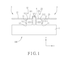
Referring to FIG. 1, a first preferred embodiment of an antenna module 100 according to the present invention is shown to include a grounding element 1, a first radiating conductor 2, a second radiating conductor 3 and a decoupling unit 4.
The grounding element 1 includes a first grounding end 11 and a second grounding end 12.
The first radiating conductor 2 includes a first feed-in portion 21, a first grounding portion 22 and a first radiating portion 23.
The first feed-in portion 21 is spaced apart from the grounding element 1, and includes a first feed-in end 211 and a first connecting end 212 opposite to the first feed-in end 211. The first feed-in end 211 is adjacent to the first grounding end 11 of the grounding element 1, and is configured to be fed with a first radio frequency signal.
The first grounding portion 22 is connected electrically between the grounding element 1 and the first connecting end 212 of the first feed-in portion 21. The first grounding portion 22 includes a first grounding segment 221 and a second grounding segment 222. The first grounding segment 221 is connected electrically to and extends from the first connecting end 212 of the first feed-in portion 21 in a −x direction toward the second radiating conductor 3. The second grounding segment 222 is connected electrically to the first grounding segment 221 opposite to the first connecting end 212 of the first feed-in portion 21. The second grounding segment 222 is substantially perpendicular to and extends from the first grounding segment 221 away from the first connecting end 212 in a −y direction to connect electrically with the grounding element 1.
The first radiating portion 23 is connected electrically to and extends from the first connecting end 212 of the first feed-in portion 21 in an x direction away from the first grounding portion 22.
The second radiating conductor 3 includes a second feed-in portion 31, a second grounding portion 32 and a second radiating portion 33.
The second feed-in portion 31 is spaced apart from the grounding element 1, and includes a second feed-in end 311 and a second connecting end 312 opposite to the second feed-in end 311. The second feed-in end 311 is adjacent to the second grounding end 12 of the grounding element 1, and is configured to be fed with a second radio frequency signal.
The second grounding portion 32 is connected electrically between the grounding element 1 and the second connecting end 312 of the second feed-in portion 31. The second grounding portion 32 includes a third grounding segment 321 and a fourth grounding segment 322. The third grounding segment 321 is connected electrically to and extends from the second connecting end 312 of the second feed-in portion 31 toward the first radiating conductor 2 in the x direction. The fourth grounding segment 322 is connected electrically to the third grounding segment 321 opposite to the second connecting end 312 of the second feed-in portion 31. The fourth grounding segment 322 is substantially perpendicular to and extends from the third grounding segment 321 away from the second connecting end 312 in the −y direction to connect electrically with the grounding element 1. It is noted that the fourth grounding segment 322 of the second radiating conductor 3 is proximate to the second grounding segment 222 of the first radiating conductor 2.
The second radiating portion 33 is connected electrically to and extends from the second connecting end 312 of the second feed-in portion 31 away from the second grounding portion 32.
In addition, the first grounding end 11 and the second grounding end 12 of this preferred embodiment are connected electrically to two conductive shields of two respective coaxial cables (not shown) for receiving grounding signals, respectively. The first feed-in end 211 and the second feed-in end 311 of this preferred embodiment are connected electrically to center cores of the coaxial cables for receiving the first radio frequency signal and the second radio frequency signal, respectively. Moreover, the first radiating conductor 2 of this preferred embodiment cooperates with the grounding element 1 to form an inverted-F antenna, and the second radiating conductor 3 of this preferred embodiment cooperates with the grounding element 1 to form another inverted-F antenna.
The decoupling unit 4 is connected electrically between a portion of the first radiating conductor 2 and a portion of the second radiating conductor 3 that are proximate to each other. In this preferred embodiment, the decoupling unit 4 is a decoupling capacitor (C) connected electrically between the second grounding segment 222 of the first grounding portion 22 of the first radiating conductor 2 and the fourth grounding segment 322 of the second grounding portion 32 of the second radiating conductor 3. The decoupling capacitor (C) may reduce an inductive coupling effect between the first and second radiating conductors 2, 3. In this preferred embodiment, the decoupling capacitor (C) is connected electrically between a portion of the second grounding segment 222 and a portion of the fourth grounding segment 322 that are away from the grounding element 1. However, the decoupling capacitor (C) may be connected electrically to other portions of the second and fourth grounding segments 222, 322 in other embodiments of the present invention.
FIG. 2 is a plot showing S-parameters of the antenna module 100 of the first preferred embodiment according to the present invention. A curve line (S11) indicates a return loss related to the first feed-in end 211 of the first feed-in portion 21 of the first radiating conductor 2. A curve line (S22) indicates a return loss related to the second feed-in end 311 of the second feed-in portion 31 of the second radiating conductor 3. A curve line (S21) indicates isolation between the first feed-in end 211 of the first radiating conductor 2 and the second feed-in end 311 of the second radiating conductor 3.
FIG. 3 is a plot showing S-parameters of an antenna module that differs from the first preferred embodiment in that the decoupling unit 4 is omitted. Comparing the curve line (S21) of FIG. 3 with the curve line (S21) of FIG. 2 under the frequency of around 1.9 GHz, it is evident that the decoupling unit 4 may effectively improve the isolation between the first and second radiating conductors 2, 3.
FIG. 4 is a radiation pattern of the first radiating conductor 2 operating with the grounding element 1 in the first preferred embodiment, and FIG. 5 is a radiation pattern of the second radiating conductor 3 operating with the grounding element 1 in the first preferred embodiment. The radiation pattern shown in FIG. 4 is substantially symmetrical with the radiation pattern shown in FIG. 5 about the y direction, and, correlation between the radiation patterns of the first and second radiating conductors 2, 3 is low. Therefore, the antenna module 100 of the first preferred embodiment is suitable to be applied to MIMO systems.
Referring to FIG. 6, a second preferred embodiment of the antenna module 100 according to the present invention is shown to be similar to the first preferred embodiment. The differences reside in the first radiating portion 23, the second radiating portion 33 and the decoupling unit 4.
In this preferred embodiment, the first radiating portion 23 includes a first connecting segment 231, a first intermediate segment 232 and a first free segment 233. The first connecting segment 231 includes a first end part 234 connected electrically to the first connecting end 212 of the first feed-in portion 21, and extends from the first connecting end 212 of the first feed-in portion 21 in the x direction away from the second radiating conductor 3. The first intermediate segment 232 is connected electrically to the first connecting segment 231 opposite to the first feed-in portion 21, and extends in the y direction away from the grounding element 1. The first free segment 233 is connected electrically to the first intermediate segment 232 opposite to the first connecting segment 231, extends in the −x direction toward the second radiating conductor 3, and includes a second end part 235 opposite to the first end part 234.
The second radiating portion 33 includes a second connecting segment 331, a second intermediate segment 332 and a second free segment 333. The second connecting segment 331 includes a third free end part 334 connected electrically to the second connecting end 312 of the second feed-in portion 31, and extends from the second connecting end 312 of the second feed-in portion 31 in the −x direction away from the first radiating conductor 2. The second intermediate segment 332 is connected electrically to the second connecting segment 331 opposite to the second feed-in portion 31, and extends in the y direction away from the grounding element 1. The second free segment 333 is connected electrically to the second intermediate segment 332 opposite to the second connecting segment 331, extends in the x direction toward the first radiating conductor 2, and includes a fourth end part 335 opposite to the third end part 334. The second end part 235 of the first radiating portion 23 is proximate to the fourth end part 335 of the second radiating portion 33.
In this embodiment, the decoupling unit 4 is a decoupling inductor (L) that is connected electrically between the second end part 235 of the first radiating portion 23 and the fourth end part 335 of the second radiating portion 33. The decoupling inductor (L) may reduce capacitive coupling effect between the first and second radiating conductors 2, 3.
FIG. 7 is a plot showing S-parameters of the antenna module 100 of the second preferred embodiment according to the present invention. FIG. 8 is a plot showing S-parameters of another antenna module that differs from the second preferred embodiment in that the decoupling unit 4 is omitted. Comparing the curve line (S21) of FIG. 7 with the curve line (S21) of FIG. 8 under the frequency of around 2.1 GHz, it is evident that the decoupling unit 4 may effectively improve the isolation between the first and second radiating conductors 2, 3.
FIG. 9 is a radiation pattern of the first radiating conductor 2 operating with the grounding element 1 in the second preferred embodiment, and FIG. 10 is a radiation pattern of the second radiating conductor 3 operating with the grounding element 1 in the second preferred embodiment. The radiation pattern shown in FIG. 9 is substantially symmetrical with the radiation pattern shown in FIG. 10 about the y axis, and, correlation between the radiation patterns of the first and second radiating conductors 2, 3 is low. Therefore, the second preferred embodiment of the antenna module 100 is suitable to be applied to MIMO systems.
Referring to FIG. 11, a third preferred embodiment of the antenna module 100 according to the present invention is shown to be similar to the first preferred embodiment. The major differences reside in the following. In this preferred embodiment, the first grounding portion 22 of the first radiating conductor 2 and the second grounding portion 32 of the second radiating conductor 3 are omitted. In other words, the first radiating conductor 2 and the grounding element 1 cooperatively form a monopole antenna, and the second radiating conductor 3 and the grounding element 1 cooperatively form another monopole antenna. The first feed-in portion 21 is proximate to the second feed-in portion 31 in this preferred embodiment. The decoupling unit 4 is the decoupling capacitor (C) connected electrically between the first feed-in portion 21 and the second feed-in portion 31. The decoupling capacitor (C) in this preferred embodiment is connected electrically between the first connecting end 212 of the first feed-in portion 21 and the second connecting end 312 of the second feed-in portion 31. However, the decoupling capacitor (C) may be connected electrically to other portions of the first and second feed-in portions 21, 31 in other embodiments of the present invention.
Referring to FIG. 12, a fourth preferred embodiment of the antenna module 100 according to the present invention is shown. In this preferred embodiment, the first grounding portion 22 of the first radiating conductor 2 and the second grounding portion 32 of the second radiating conductor 3 are omitted. In other words, the first radiating conductor 2 and the grounding element 1 cooperatively form a monopole antenna, and the second radiating conductor 3 and the grounding element 1 cooperatively form another monopole antenna. Moreover, the first radiating portion 23 is an elongated conductor extending from the first connecting end 212 of the first feed-in portion 21 in the −x direction toward the second radiating conductor 3. The second radiating portion 33 is an elongated conductor extending from the second connecting end 312 of the second feed-in portion 31 in the x direction toward the first radiating conductor 2. Similar to the second preferred embodiment, the second end part 235 of the first radiating portion 23 in this preferred embodiment is proximate to the fourth end part 335 of the second radiating portion 33. The decoupling unit 4 is the decoupling inductor (L) connected electrically between the second end part 235 and the fourth end part 335.
To conclude, according to the present invention, the decoupling unit 4 (i.e., the decoupling capacitor (C) or the decoupling inductor (L)) of the antenna module 100 are connected electrically between the positions of the first radiating conductor 2 and the second radiating conductor 3 that are proximate to each other, such that the inductive/capacitive coupling effect between the first radiating conductor 2 and the second radiating conductor 3 may be reduced. Therefore, the isolation between the first radiating conductor 2 and the second radiating conductor 3 under operation of the antenna module 100 may be improved, and signal transmission performance may be maintained. Further, the antenna module 100 may have a relatively small size.
While the present invention has been described in connection with what are considered the most practical and preferred embodiments, it is understood that this invention is not limited to the disclosed embodiments but is intended to cover various arrangements included within the spirit and scope of the broadest interpretation so as to encompass all such modifications and equivalent arrangements.

Claims (2)

What is claimed is:
1. An antenna module, comprising:
a grounding element including a first grounding end and a second grounding end;
a first radiating conductor including a first feed-in end that is adjacent to and spaced apart from said first grounding end of said grounding element and that is configured to be fed with a first radio frequency signal, said first radiating conductor including a first feed-in portion spaced apart from said grounding element and including said first feed-in end and a first connecting end opposite to said first feed-in end, a first grounding portion connected electrically between said grounding element and said first connecting end of said first feed-in portion, and a first radiating portion connected electrically to said first connecting end of said first feed-in portion;
a second radiating conductor adjacent to and spaced from said first radiating conductor, and including a second feed-in end that is adjacent to and spaced apart from said second grounding end of said grounding element and that is configured to be fed with a second radio frequency signal, said second radiating conductor including a second feed-in portion spaced apart from said grounding element and including said second feed-in end and a second connecting end opposite to said second feed-in end, a second grounding portion connected electrically between said grounding element and said second connecting end of said second feed-in portion and being proximate to said first grounding portion, and a second radiating portion connected electrically to said second connecting end of said second feed-in portion; and
a decoupling unit connected electrically between a portion of said first radiating conductor and a portion of said second radiating conductor that are proximate to each other, and being one of a decoupling capacitor and a decoupling inductor, said decoupling unit being a decoupling capacitor connected electrically between said first grounding portion and said second grounding portion,
wherein:
said first grounding portion includes a first grounding segment that extends from said first connecting end toward said second radiating conductor, and a second grounding segment that is substantially perpendicular to said first grounding segment and that is connected electrically between said grounding element and said first grounding segment;
said second grounding portion includes a third grounding segment that extends from said second connecting end toward said first radiating conductor, and a fourth grounding segment that is substantially perpendicular to said third grounding segment and that is connected electrically between said grounding element and said third grounding segment; and
said decoupling unit is connected electrically between said first grounding segment and said third grounding segment.
2. The antenna module as claimed in claim 1, wherein said first and second grounding ends of said grounding element are configured to be connected electrically to two conductive shields of respective two coaxial cables for receiving ground signals, respectively.
US14/303,028 2013-09-05 2014-06-12 Antenna module Expired - Fee Related US9450302B2 (en)

Applications Claiming Priority (3)

Application Number Priority Date Filing Date Title
TW102131999 2013-09-05
TW102131999A TW201511407A (en) 2013-09-05 2013-09-05 Antenna module
TW102131999A 2013-09-05

Publications (2)

Publication Number Publication Date
US20150061962A1 US20150061962A1 (en) 2015-03-05
US9450302B2 true US9450302B2 (en) 2016-09-20

Family

ID=52582462

Family Applications (1)

Application Number Title Priority Date Filing Date
US14/303,028 Expired - Fee Related US9450302B2 (en) 2013-09-05 2014-06-12 Antenna module

Country Status (3)

Country Link
US (1) US9450302B2 (en)
CN (1) CN104425891A (en)
TW (1) TW201511407A (en)

Cited By (1)

* Cited by examiner, † Cited by third party
Publication number Priority date Publication date Assignee Title
US11145990B2 (en) * 2018-03-21 2021-10-12 Wistron Neweb Corporation Antenna structure having multiple operating frequency bands

Families Citing this family (15)

* Cited by examiner, † Cited by third party
Publication number Priority date Publication date Assignee Title
TWI565137B (en) * 2014-04-11 2017-01-01 Quanta Comp Inc Broadband antenna module
TWI590524B (en) * 2014-10-15 2017-07-01 宏碁股份有限公司 Antenna system
CN105305081A (en) * 2015-12-10 2016-02-03 歌尔声学股份有限公司 Antenna device and mobile terminal
TWI619313B (en) 2016-04-29 2018-03-21 和碩聯合科技股份有限公司 Electronic apparatus and dual band printed antenna of the same
TWI629835B (en) * 2016-07-21 2018-07-11 和碩聯合科技股份有限公司 Antenna unit, antenna system and antenna control method
CN109309283A (en) * 2017-07-27 2019-02-05 国基电子(上海)有限公司 Antenna assembly
JP6903158B2 (en) * 2017-11-30 2021-07-14 株式会社ソニー・インタラクティブエンタテインメント Communication equipment
CN109546337B (en) * 2018-11-13 2020-11-10 北京理工大学 Compact 5G mobile terminal MIMO antenna
KR102614045B1 (en) 2019-01-25 2023-12-15 삼성전자주식회사 Electronic device having a plurality of antennas
CN110137664B (en) * 2019-05-08 2020-06-23 清华大学 Double-antenna integrated broadband 5G MIMO terminal antenna
CN110364809B (en) * 2019-06-30 2021-11-16 RealMe重庆移动通信有限公司 Wearable electronic equipment
CN111276806B (en) * 2020-02-14 2023-01-24 维沃移动通信有限公司 Antenna and electronic equipment
US11569585B2 (en) * 2020-12-30 2023-01-31 Industrial Technology Research Institute Highly integrated pattern-variable multi-antenna array
TWI765621B (en) * 2021-03-25 2022-05-21 神準科技股份有限公司 Dual feed antenna
WO2022210828A1 (en) * 2021-03-31 2022-10-06 原田工業株式会社 Antenna device

Citations (11)

* Cited by examiner, † Cited by third party
Publication number Priority date Publication date Assignee Title
US20080174508A1 (en) * 2007-01-19 2008-07-24 Hiroshi Iwai Array antenna apparatus having at least two feeding elements and operable in multiple frequency bands
USD606058S1 (en) 2009-02-13 2009-12-15 Skycross, Inc. Antenna structure
US8085202B2 (en) 2009-03-17 2011-12-27 Research In Motion Limited Wideband, high isolation two port antenna array for multiple input, multiple output handheld devices
US20130057438A1 (en) * 2010-05-13 2013-03-07 Panasonic Corporation Antenna device and portable wireless terminal equipped with the same
US20130120201A1 (en) * 2011-11-14 2013-05-16 Samsung Electronics Co. Ltd. Electronic apparatus for isolating signal generation device
US20130162497A1 (en) * 2011-05-19 2013-06-27 Panasonic Corporation Antenna
US20130257674A1 (en) * 2012-04-03 2013-10-03 Industrial Technology Research Institute Multi-band multi-antenna system and communiction device thereof
US20130328742A1 (en) * 2011-04-20 2013-12-12 Panasonic Corporation Antenna device and portable wireless terminal equipped with same
US20140313089A1 (en) * 2013-04-18 2014-10-23 Industrial Technology Research Institute Multi-antenna system
US20150255864A1 (en) * 2012-09-27 2015-09-10 Zte Corporation Multiple-input multiple-output antenna, system and mobile terminal
US20150295312A1 (en) * 2014-04-11 2015-10-15 Quanta Computer Inc. Wideband antenna module

Family Cites Families (3)

* Cited by examiner, † Cited by third party
Publication number Priority date Publication date Assignee Title
CN102570028A (en) * 2010-12-08 2012-07-11 上海安费诺永亿通讯电子有限公司 System and method for realizing high isolation of antennas between adjacent frequency bands
US8890763B2 (en) * 2011-02-21 2014-11-18 Funai Electric Co., Ltd. Multiantenna unit and communication apparatus
JP5626024B2 (en) * 2011-03-02 2014-11-19 船井電機株式会社 Multi-antenna device and communication device

Patent Citations (11)

* Cited by examiner, † Cited by third party
Publication number Priority date Publication date Assignee Title
US20080174508A1 (en) * 2007-01-19 2008-07-24 Hiroshi Iwai Array antenna apparatus having at least two feeding elements and operable in multiple frequency bands
USD606058S1 (en) 2009-02-13 2009-12-15 Skycross, Inc. Antenna structure
US8085202B2 (en) 2009-03-17 2011-12-27 Research In Motion Limited Wideband, high isolation two port antenna array for multiple input, multiple output handheld devices
US20130057438A1 (en) * 2010-05-13 2013-03-07 Panasonic Corporation Antenna device and portable wireless terminal equipped with the same
US20130328742A1 (en) * 2011-04-20 2013-12-12 Panasonic Corporation Antenna device and portable wireless terminal equipped with same
US20130162497A1 (en) * 2011-05-19 2013-06-27 Panasonic Corporation Antenna
US20130120201A1 (en) * 2011-11-14 2013-05-16 Samsung Electronics Co. Ltd. Electronic apparatus for isolating signal generation device
US20130257674A1 (en) * 2012-04-03 2013-10-03 Industrial Technology Research Institute Multi-band multi-antenna system and communiction device thereof
US20150255864A1 (en) * 2012-09-27 2015-09-10 Zte Corporation Multiple-input multiple-output antenna, system and mobile terminal
US20140313089A1 (en) * 2013-04-18 2014-10-23 Industrial Technology Research Institute Multi-antenna system
US20150295312A1 (en) * 2014-04-11 2015-10-15 Quanta Computer Inc. Wideband antenna module

Cited By (1)

* Cited by examiner, † Cited by third party
Publication number Priority date Publication date Assignee Title
US11145990B2 (en) * 2018-03-21 2021-10-12 Wistron Neweb Corporation Antenna structure having multiple operating frequency bands

Also Published As

Publication number Publication date
US20150061962A1 (en) 2015-03-05
CN104425891A (en) 2015-03-18
TW201511407A (en) 2015-03-16

Similar Documents

Publication Publication Date Title
US9450302B2 (en) Antenna module
US9590304B2 (en) Broadband antenna
US9425498B2 (en) Wideband antenna module
US9660326B2 (en) Conductive loop antennas
US9401543B2 (en) Broadband antenna
TWI411160B (en) Antenna and communication device having same
KR101638798B1 (en) Apparatus for multiple antennas in wireless communication system
US9748661B2 (en) Antenna for achieving effects of MIMO antenna
US9118117B2 (en) Receiving and transmitting device for wireless transceiver
US9397405B2 (en) Antenna device
US9013358B2 (en) Antenna assembly and wireless communication device provided with the same
US9281558B2 (en) High isolation electromagnetic transmitter and receiver
US9673531B2 (en) Antenna
EP3185354A1 (en) Antenna component and electronic device
US20170170555A1 (en) Decoupled Antennas For Wireless Communication
US11081785B2 (en) Antenna module
US8836605B2 (en) Embedded antenna
US20140347247A1 (en) Antenna device for electronic device
US20150180117A1 (en) Inverted-f antenna provided with an isolation unit
TWI533506B (en) Communication device and wideband decoupled dual-antenna element therein
US20080094303A1 (en) Planer inverted-F antenna device
US10790587B2 (en) Multiband antenna and radio communication apparatus
TW202036986A (en) Dual-band antenna
US10862214B2 (en) Antenna
US11233322B2 (en) Communication device

Legal Events

Date Code Title Description
AS Assignment

Owner name: QUANTA COMPUTER INC., TAIWAN

Free format text: ASSIGNMENT OF ASSIGNORS INTEREST;ASSIGNORS:LEE, CHI-HSUAN;TENG, PEI-LING;CHEN, KUO-CHENG;REEL/FRAME:033091/0130

Effective date: 20140521

STCF Information on status: patent grant

Free format text: PATENTED CASE

FEPP Fee payment procedure

Free format text: MAINTENANCE FEE REMINDER MAILED (ORIGINAL EVENT CODE: REM.); ENTITY STATUS OF PATENT OWNER: LARGE ENTITY

LAPS Lapse for failure to pay maintenance fees

Free format text: PATENT EXPIRED FOR FAILURE TO PAY MAINTENANCE FEES (ORIGINAL EVENT CODE: EXP.); ENTITY STATUS OF PATENT OWNER: LARGE ENTITY

STCH Information on status: patent discontinuation

Free format text: PATENT EXPIRED DUE TO NONPAYMENT OF MAINTENANCE FEES UNDER 37 CFR 1.362

FP Expired due to failure to pay maintenance fee

Effective date: 20200920