US9451162B2 - Camera array including camera modules - Google Patents
Camera array including camera modules Download PDFInfo
- Publication number
- US9451162B2 US9451162B2 US14/444,938 US201414444938A US9451162B2 US 9451162 B2 US9451162 B2 US 9451162B2 US 201414444938 A US201414444938 A US 201414444938A US 9451162 B2 US9451162 B2 US 9451162B2
- Authority
- US
- United States
- Prior art keywords
- camera
- camera module
- module
- modules
- array
- Prior art date
- Legal status (The legal status is an assumption and is not a legal conclusion. Google has not performed a legal analysis and makes no representation as to the accuracy of the status listed.)
- Active
Links
- 230000015654 memory Effects 0.000 claims abstract description 51
- 230000002776 aggregation Effects 0.000 claims description 28
- 238000004220 aggregation Methods 0.000 claims description 28
- 230000007812 deficiency Effects 0.000 claims description 14
- 230000001360 synchronised effect Effects 0.000 claims description 12
- 238000012546 transfer Methods 0.000 claims description 6
- 230000001133 acceleration Effects 0.000 claims description 2
- 230000000007 visual effect Effects 0.000 claims 4
- 230000006854 communication Effects 0.000 description 52
- 238000004891 communication Methods 0.000 description 52
- 238000000034 method Methods 0.000 description 30
- 238000001514 detection method Methods 0.000 description 22
- 238000003860 storage Methods 0.000 description 22
- 238000012937 correction Methods 0.000 description 14
- 238000004422 calculation algorithm Methods 0.000 description 10
- 239000000463 material Substances 0.000 description 10
- 230000006870 function Effects 0.000 description 8
- 230000008569 process Effects 0.000 description 8
- 230000000977 initiatory effect Effects 0.000 description 7
- 230000003287 optical effect Effects 0.000 description 6
- 238000012545 processing Methods 0.000 description 6
- 238000010586 diagram Methods 0.000 description 4
- 230000017525 heat dissipation Effects 0.000 description 4
- XLYOFNOQVPJJNP-UHFFFAOYSA-N water Substances O XLYOFNOQVPJJNP-UHFFFAOYSA-N 0.000 description 4
- 230000010267 cellular communication Effects 0.000 description 3
- 230000007246 mechanism Effects 0.000 description 3
- 239000002184 metal Substances 0.000 description 3
- 238000012986 modification Methods 0.000 description 3
- 230000004048 modification Effects 0.000 description 3
- 230000004044 response Effects 0.000 description 3
- 239000004065 semiconductor Substances 0.000 description 3
- 230000003068 static effect Effects 0.000 description 3
- 241001425390 Aphis fabae Species 0.000 description 2
- 238000007792 addition Methods 0.000 description 2
- 230000004931 aggregating effect Effects 0.000 description 2
- 230000008901 benefit Effects 0.000 description 2
- 239000003086 colorant Substances 0.000 description 2
- 230000008878 coupling Effects 0.000 description 2
- 238000010168 coupling process Methods 0.000 description 2
- 238000005859 coupling reaction Methods 0.000 description 2
- 230000000694 effects Effects 0.000 description 2
- 238000005516 engineering process Methods 0.000 description 2
- 238000004519 manufacturing process Methods 0.000 description 2
- 101001093748 Homo sapiens Phosphatidylinositol N-acetylglucosaminyltransferase subunit P Proteins 0.000 description 1
- 241000287181 Sturnus vulgaris Species 0.000 description 1
- 230000004075 alteration Effects 0.000 description 1
- 238000003491 array Methods 0.000 description 1
- 230000009286 beneficial effect Effects 0.000 description 1
- 230000007175 bidirectional communication Effects 0.000 description 1
- 230000005540 biological transmission Effects 0.000 description 1
- 238000007664 blowing Methods 0.000 description 1
- 238000004364 calculation method Methods 0.000 description 1
- 230000008859 change Effects 0.000 description 1
- 230000000295 complement effect Effects 0.000 description 1
- 230000006835 compression Effects 0.000 description 1
- 238000007906 compression Methods 0.000 description 1
- 238000004590 computer program Methods 0.000 description 1
- 238000012790 confirmation Methods 0.000 description 1
- 238000001816 cooling Methods 0.000 description 1
- 238000013461 design Methods 0.000 description 1
- 238000009826 distribution Methods 0.000 description 1
- 238000009499 grossing Methods 0.000 description 1
- 238000003384 imaging method Methods 0.000 description 1
- 230000002452 interceptive effect Effects 0.000 description 1
- 238000012544 monitoring process Methods 0.000 description 1
- APTZNLHMIGJTEW-UHFFFAOYSA-N pyraflufen-ethyl Chemical compound C1=C(Cl)C(OCC(=O)OCC)=CC(C=2C(=C(OC(F)F)N(C)N=2)Cl)=C1F APTZNLHMIGJTEW-UHFFFAOYSA-N 0.000 description 1
- 239000007787 solid Substances 0.000 description 1
- 238000006467 substitution reaction Methods 0.000 description 1
- 230000002194 synthesizing effect Effects 0.000 description 1
- 238000013022 venting Methods 0.000 description 1
Images


Classifications
-
- H—ELECTRICITY
- H04—ELECTRIC COMMUNICATION TECHNIQUE
- H04N—PICTORIAL COMMUNICATION, e.g. TELEVISION
- H04N23/00—Cameras or camera modules comprising electronic image sensors; Control thereof
- H04N23/90—Arrangement of cameras or camera modules, e.g. multiple cameras in TV studios or sports stadiums
-
- H04N5/23238—
-
- H—ELECTRICITY
- H04—ELECTRIC COMMUNICATION TECHNIQUE
- H04N—PICTORIAL COMMUNICATION, e.g. TELEVISION
- H04N13/00—Stereoscopic video systems; Multi-view video systems; Details thereof
- H04N13/10—Processing, recording or transmission of stereoscopic or multi-view image signals
- H04N13/106—Processing image signals
- H04N13/111—Transformation of image signals corresponding to virtual viewpoints, e.g. spatial image interpolation
- H04N13/117—Transformation of image signals corresponding to virtual viewpoints, e.g. spatial image interpolation the virtual viewpoint locations being selected by the viewers or determined by viewer tracking
-
- G—PHYSICS
- G06—COMPUTING; CALCULATING OR COUNTING
- G06F—ELECTRIC DIGITAL DATA PROCESSING
- G06F3/00—Input arrangements for transferring data to be processed into a form capable of being handled by the computer; Output arrangements for transferring data from processing unit to output unit, e.g. interface arrangements
- G06F3/01—Input arrangements or combined input and output arrangements for interaction between user and computer
- G06F3/011—Arrangements for interaction with the human body, e.g. for user immersion in virtual reality
- G06F3/013—Eye tracking input arrangements
-
- G—PHYSICS
- G06—COMPUTING; CALCULATING OR COUNTING
- G06F—ELECTRIC DIGITAL DATA PROCESSING
- G06F3/00—Input arrangements for transferring data to be processed into a form capable of being handled by the computer; Output arrangements for transferring data from processing unit to output unit, e.g. interface arrangements
- G06F3/01—Input arrangements or combined input and output arrangements for interaction between user and computer
- G06F3/048—Interaction techniques based on graphical user interfaces [GUI]
- G06F3/0481—Interaction techniques based on graphical user interfaces [GUI] based on specific properties of the displayed interaction object or a metaphor-based environment, e.g. interaction with desktop elements like windows or icons, or assisted by a cursor's changing behaviour or appearance
- G06F3/04815—Interaction with a metaphor-based environment or interaction object displayed as three-dimensional, e.g. changing the user viewpoint with respect to the environment or object
-
- G—PHYSICS
- G06—COMPUTING; CALCULATING OR COUNTING
- G06F—ELECTRIC DIGITAL DATA PROCESSING
- G06F3/00—Input arrangements for transferring data to be processed into a form capable of being handled by the computer; Output arrangements for transferring data from processing unit to output unit, e.g. interface arrangements
- G06F3/01—Input arrangements or combined input and output arrangements for interaction between user and computer
- G06F3/048—Interaction techniques based on graphical user interfaces [GUI]
- G06F3/0484—Interaction techniques based on graphical user interfaces [GUI] for the control of specific functions or operations, e.g. selecting or manipulating an object, an image or a displayed text element, setting a parameter value or selecting a range
- G06F3/04847—Interaction techniques to control parameter settings, e.g. interaction with sliders or dials
-
- G—PHYSICS
- G06—COMPUTING; CALCULATING OR COUNTING
- G06Q—INFORMATION AND COMMUNICATION TECHNOLOGY [ICT] SPECIALLY ADAPTED FOR ADMINISTRATIVE, COMMERCIAL, FINANCIAL, MANAGERIAL OR SUPERVISORY PURPOSES; SYSTEMS OR METHODS SPECIALLY ADAPTED FOR ADMINISTRATIVE, COMMERCIAL, FINANCIAL, MANAGERIAL OR SUPERVISORY PURPOSES, NOT OTHERWISE PROVIDED FOR
- G06Q30/00—Commerce
- G06Q30/02—Marketing; Price estimation or determination; Fundraising
- G06Q30/0241—Advertisements
- G06Q30/0242—Determining effectiveness of advertisements
- G06Q30/0246—Traffic
-
- G—PHYSICS
- G06—COMPUTING; CALCULATING OR COUNTING
- G06Q—INFORMATION AND COMMUNICATION TECHNOLOGY [ICT] SPECIALLY ADAPTED FOR ADMINISTRATIVE, COMMERCIAL, FINANCIAL, MANAGERIAL OR SUPERVISORY PURPOSES; SYSTEMS OR METHODS SPECIALLY ADAPTED FOR ADMINISTRATIVE, COMMERCIAL, FINANCIAL, MANAGERIAL OR SUPERVISORY PURPOSES, NOT OTHERWISE PROVIDED FOR
- G06Q30/00—Commerce
- G06Q30/02—Marketing; Price estimation or determination; Fundraising
- G06Q30/0241—Advertisements
- G06Q30/0251—Targeted advertisements
- G06Q30/0263—Targeted advertisements based upon Internet or website rating
-
- G—PHYSICS
- G06—COMPUTING; CALCULATING OR COUNTING
- G06Q—INFORMATION AND COMMUNICATION TECHNOLOGY [ICT] SPECIALLY ADAPTED FOR ADMINISTRATIVE, COMMERCIAL, FINANCIAL, MANAGERIAL OR SUPERVISORY PURPOSES; SYSTEMS OR METHODS SPECIALLY ADAPTED FOR ADMINISTRATIVE, COMMERCIAL, FINANCIAL, MANAGERIAL OR SUPERVISORY PURPOSES, NOT OTHERWISE PROVIDED FOR
- G06Q30/00—Commerce
- G06Q30/02—Marketing; Price estimation or determination; Fundraising
- G06Q30/0241—Advertisements
- G06Q30/0251—Targeted advertisements
- G06Q30/0269—Targeted advertisements based on user profile or attribute
-
- G—PHYSICS
- G06—COMPUTING; CALCULATING OR COUNTING
- G06Q—INFORMATION AND COMMUNICATION TECHNOLOGY [ICT] SPECIALLY ADAPTED FOR ADMINISTRATIVE, COMMERCIAL, FINANCIAL, MANAGERIAL OR SUPERVISORY PURPOSES; SYSTEMS OR METHODS SPECIALLY ADAPTED FOR ADMINISTRATIVE, COMMERCIAL, FINANCIAL, MANAGERIAL OR SUPERVISORY PURPOSES, NOT OTHERWISE PROVIDED FOR
- G06Q30/00—Commerce
- G06Q30/02—Marketing; Price estimation or determination; Fundraising
- G06Q30/0241—Advertisements
- G06Q30/0277—Online advertisement
-
- G—PHYSICS
- G06—COMPUTING; CALCULATING OR COUNTING
- G06Q—INFORMATION AND COMMUNICATION TECHNOLOGY [ICT] SPECIALLY ADAPTED FOR ADMINISTRATIVE, COMMERCIAL, FINANCIAL, MANAGERIAL OR SUPERVISORY PURPOSES; SYSTEMS OR METHODS SPECIALLY ADAPTED FOR ADMINISTRATIVE, COMMERCIAL, FINANCIAL, MANAGERIAL OR SUPERVISORY PURPOSES, NOT OTHERWISE PROVIDED FOR
- G06Q50/00—Systems or methods specially adapted for specific business sectors, e.g. utilities or tourism
- G06Q50/01—Social networking
-
- G—PHYSICS
- G06—COMPUTING; CALCULATING OR COUNTING
- G06T—IMAGE DATA PROCESSING OR GENERATION, IN GENERAL
- G06T19/00—Manipulating 3D models or images for computer graphics
- G06T19/006—Mixed reality
-
- G—PHYSICS
- G06—COMPUTING; CALCULATING OR COUNTING
- G06T—IMAGE DATA PROCESSING OR GENERATION, IN GENERAL
- G06T3/00—Geometric image transformation in the plane of the image
- G06T3/40—Scaling the whole image or part thereof
- G06T3/4038—Scaling the whole image or part thereof for image mosaicing, i.e. plane images composed of plane sub-images
-
- G06T7/0022—
-
- G—PHYSICS
- G06—COMPUTING; CALCULATING OR COUNTING
- G06T—IMAGE DATA PROCESSING OR GENERATION, IN GENERAL
- G06T7/00—Image analysis
- G06T7/97—Determining parameters from multiple pictures
-
- G—PHYSICS
- G11—INFORMATION STORAGE
- G11B—INFORMATION STORAGE BASED ON RELATIVE MOVEMENT BETWEEN RECORD CARRIER AND TRANSDUCER
- G11B27/00—Editing; Indexing; Addressing; Timing or synchronising; Monitoring; Measuring tape travel
- G11B27/10—Indexing; Addressing; Timing or synchronising; Measuring tape travel
- G11B27/11—Indexing; Addressing; Timing or synchronising; Measuring tape travel by using information not detectable on the record carrier
-
- G—PHYSICS
- G11—INFORMATION STORAGE
- G11B—INFORMATION STORAGE BASED ON RELATIVE MOVEMENT BETWEEN RECORD CARRIER AND TRANSDUCER
- G11B27/00—Editing; Indexing; Addressing; Timing or synchronising; Monitoring; Measuring tape travel
- G11B27/10—Indexing; Addressing; Timing or synchronising; Measuring tape travel
- G11B27/34—Indicating arrangements
-
- G—PHYSICS
- G11—INFORMATION STORAGE
- G11B—INFORMATION STORAGE BASED ON RELATIVE MOVEMENT BETWEEN RECORD CARRIER AND TRANSDUCER
- G11B31/00—Arrangements for the associated working of recording or reproducing apparatus with related apparatus
- G11B31/006—Arrangements for the associated working of recording or reproducing apparatus with related apparatus with video camera or receiver
-
- H04N13/0007—
-
- H04N13/0011—
-
- H04N13/0242—
-
- H04N13/0271—
-
- H—ELECTRICITY
- H04—ELECTRIC COMMUNICATION TECHNIQUE
- H04N—PICTORIAL COMMUNICATION, e.g. TELEVISION
- H04N13/00—Stereoscopic video systems; Multi-view video systems; Details thereof
- H04N13/10—Processing, recording or transmission of stereoscopic or multi-view image signals
- H04N13/106—Processing image signals
- H04N13/111—Transformation of image signals corresponding to virtual viewpoints, e.g. spatial image interpolation
-
- H—ELECTRICITY
- H04—ELECTRIC COMMUNICATION TECHNIQUE
- H04N—PICTORIAL COMMUNICATION, e.g. TELEVISION
- H04N13/00—Stereoscopic video systems; Multi-view video systems; Details thereof
- H04N13/10—Processing, recording or transmission of stereoscopic or multi-view image signals
- H04N13/189—Recording image signals; Reproducing recorded image signals
-
- H—ELECTRICITY
- H04—ELECTRIC COMMUNICATION TECHNIQUE
- H04N—PICTORIAL COMMUNICATION, e.g. TELEVISION
- H04N13/00—Stereoscopic video systems; Multi-view video systems; Details thereof
- H04N13/20—Image signal generators
- H04N13/204—Image signal generators using stereoscopic image cameras
- H04N13/243—Image signal generators using stereoscopic image cameras using three or more 2D image sensors
-
- H—ELECTRICITY
- H04—ELECTRIC COMMUNICATION TECHNIQUE
- H04N—PICTORIAL COMMUNICATION, e.g. TELEVISION
- H04N13/00—Stereoscopic video systems; Multi-view video systems; Details thereof
- H04N13/20—Image signal generators
- H04N13/271—Image signal generators wherein the generated image signals comprise depth maps or disparity maps
-
- H—ELECTRICITY
- H04—ELECTRIC COMMUNICATION TECHNIQUE
- H04N—PICTORIAL COMMUNICATION, e.g. TELEVISION
- H04N13/00—Stereoscopic video systems; Multi-view video systems; Details thereof
- H04N13/20—Image signal generators
- H04N13/282—Image signal generators for generating image signals corresponding to three or more geometrical viewpoints, e.g. multi-view systems
-
- H—ELECTRICITY
- H04—ELECTRIC COMMUNICATION TECHNIQUE
- H04N—PICTORIAL COMMUNICATION, e.g. TELEVISION
- H04N23/00—Cameras or camera modules comprising electronic image sensors; Control thereof
- H04N23/60—Control of cameras or camera modules
- H04N23/66—Remote control of cameras or camera parts, e.g. by remote control devices
- H04N23/661—Transmitting camera control signals through networks, e.g. control via the Internet
-
- H—ELECTRICITY
- H04—ELECTRIC COMMUNICATION TECHNIQUE
- H04N—PICTORIAL COMMUNICATION, e.g. TELEVISION
- H04N23/00—Cameras or camera modules comprising electronic image sensors; Control thereof
- H04N23/60—Control of cameras or camera modules
- H04N23/698—Control of cameras or camera modules for achieving an enlarged field of view, e.g. panoramic image capture
-
- G—PHYSICS
- G06—COMPUTING; CALCULATING OR COUNTING
- G06Q—INFORMATION AND COMMUNICATION TECHNOLOGY [ICT] SPECIALLY ADAPTED FOR ADMINISTRATIVE, COMMERCIAL, FINANCIAL, MANAGERIAL OR SUPERVISORY PURPOSES; SYSTEMS OR METHODS SPECIALLY ADAPTED FOR ADMINISTRATIVE, COMMERCIAL, FINANCIAL, MANAGERIAL OR SUPERVISORY PURPOSES, NOT OTHERWISE PROVIDED FOR
- G06Q30/00—Commerce
- G06Q30/02—Marketing; Price estimation or determination; Fundraising
- G06Q30/0241—Advertisements
- G06Q30/0273—Determination of fees for advertising
-
- G—PHYSICS
- G06—COMPUTING; CALCULATING OR COUNTING
- G06Q—INFORMATION AND COMMUNICATION TECHNOLOGY [ICT] SPECIALLY ADAPTED FOR ADMINISTRATIVE, COMMERCIAL, FINANCIAL, MANAGERIAL OR SUPERVISORY PURPOSES; SYSTEMS OR METHODS SPECIALLY ADAPTED FOR ADMINISTRATIVE, COMMERCIAL, FINANCIAL, MANAGERIAL OR SUPERVISORY PURPOSES, NOT OTHERWISE PROVIDED FOR
- G06Q30/00—Commerce
- G06Q30/02—Marketing; Price estimation or determination; Fundraising
- G06Q30/0283—Price estimation or determination
- G06Q30/0284—Time or distance, e.g. usage of parking meters or taximeters
-
- G—PHYSICS
- G06—COMPUTING; CALCULATING OR COUNTING
- G06T—IMAGE DATA PROCESSING OR GENERATION, IN GENERAL
- G06T2207/00—Indexing scheme for image analysis or image enhancement
- G06T2207/10—Image acquisition modality
- G06T2207/10004—Still image; Photographic image
- G06T2207/10012—Stereo images
-
- G—PHYSICS
- G06—COMPUTING; CALCULATING OR COUNTING
- G06T—IMAGE DATA PROCESSING OR GENERATION, IN GENERAL
- G06T2207/00—Indexing scheme for image analysis or image enhancement
- G06T2207/20—Special algorithmic details
- G06T2207/20228—Disparity calculation for image-based rendering
-
- H—ELECTRICITY
- H04—ELECTRIC COMMUNICATION TECHNIQUE
- H04N—PICTORIAL COMMUNICATION, e.g. TELEVISION
- H04N13/00—Stereoscopic video systems; Multi-view video systems; Details thereof
- H04N13/20—Image signal generators
- H04N13/204—Image signal generators using stereoscopic image cameras
-
- H—ELECTRICITY
- H04—ELECTRIC COMMUNICATION TECHNIQUE
- H04N—PICTORIAL COMMUNICATION, e.g. TELEVISION
- H04N7/00—Television systems
- H04N7/18—Closed-circuit television [CCTV] systems, i.e. systems in which the video signal is not broadcast
- H04N7/181—Closed-circuit television [CCTV] systems, i.e. systems in which the video signal is not broadcast for receiving images from a plurality of remote sources
Definitions
- the embodiments discussed herein are related to a camera system. More particularly, the embodiments discussed herein relate to a camera system including one or more camera modules for recording images.
- Existing camera systems using multiple cameras to record videos in different locations or the same location may generate videos with poor quality.
- cameras in a security system may capture videos independently without considering synchronization between the different cameras.
- Each camera may operate independently from the other cameras with no coordination between the different cameras.
- a camera system comprises a camera array comprising camera modules, the camera modules comprising a master camera that includes a processor, a memory, a sensor, a lens, a status indicator, and a switch, the switch configured to instruct the camera modules to initiate a start operation to start recording video data using the lens and the sensor in each of the camera modules and the switch configured to instruct the camera modules to initiate a stop operation to stop recording, the status indicator configured to indicate a status of at least one of the camera modules or the camera array.
- another innovative aspect of the subject matter described in this disclosure may be embodied in methods that include: housing forming apertures for the camera modules and wherein the camera modules comprise housing that is rotationally symmetrical; housing in the shape of a honeycomb, the center of each compartment of the honeycomb forming an aperture for one of the camera modules; a microphone array configured to capture audio for enabling reconstruction of sound from any arbitrary direction; an aggregation system for generating a stream of three-dimensional video and audio data for displaying panoramic images; a viewing system configured to decode and render the three-dimensional video and play the audio data on a virtual reality display and surround sound system; a connection hub linking the camera modules and configured to transfer the video data from at least one of the camera modules to a client device, the connection hub including a battery for supplying power to each of the camera modules.
- the features include: the camera modules forming a daisy chain with the master camera being coupled to a first camera module that is coupled to an “n” camera module that is coupled to the master camera; each camera module being positioned to have at least one overlapping field of view with another camera module; the status of one of the camera modules including a faulty status and the status indicator indicating the faulty status responsive to a fault occurring in one of the camera modules; the status indicator being an overall status indicator configured to indicate the faulty status of a fault occurring in any of the camera modules and wherein the camera modules further include individual status indicators configured to indicate the fault status of the fault occurring in one of the camera modules; the camera modules being synchronized through a daisy chain to capture corresponding video data in different directions simultaneously; wherein the camera modules pass control and status messages to one another via the daisy chain.
- a method comprises identifying, with one or more processors, a device identifier and a position of each camera module in a camera array, the camera modules including a master camera; confirming an absence of faults in the camera module; initiating a start operation in the master camera, the master camera instructing the other camera modules to start recording; receiving video data comprising image frames from the camera modules; stitching the image frames together based on the video data; generating three-dimensional video; synchronize audio data; and generating a stream of the three-dimensional video and the audio data for displaying panoramic images.
- the method is further configured to perform geometric calibration to identify a relative position of each camera module.
- the image frames are stitched together based on calibration relative position of each camera module.
- the method is further configured to generate a user interface for viewing video data from one of the camera modules
- the disclosure is particularly advantageous in a number of respects.
- the camera array generates a realistic three-dimensional experience for users.
- the camera modules are designed to be rotationally symmetrical with interchangeable components, which makes modifications easier to implement.
- the aggregation system includes a user interface for allowing a user to view different levels of detail including a preview of the virtual reality experience, and the images from individual camera modules.
- FIG. 1 illustrates a block diagram of some embodiments of an example camera system for recording video data using one or more camera modules
- FIG. 2 illustrates a block diagram of some embodiments of an example aggregation system
- FIG. 3A illustrates an example system comprising a camera array and a connection hub according to some embodiments
- FIG. 3B illustrates an example housing according to some embodiments
- FIG. 3C illustrates an example microphone array according to some embodiments
- FIG. 4 illustrates an example method for providing video data using a camera array according to some embodiments.
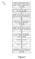
- FIG. 5 illustrates an example method for detecting a faulty camera module according to some embodiments.
- the disclosure relates to a camera system that includes a camera array with one or more camera modules.
- Applications for the camera system may include, but are not limited to, a rear camera system for a vehicle, a robot installed with a camera array including one or more camera modules, a high-end filming tool, and other suitable applications with virtual presence.
- one application of the camera system may include providing a virtual reality (VR) experience to users.
- An ideal virtual reality experience is one that creates a realistic sense of being in another place. Creating such an experience may involve reproducing three dimensional (3D) video for a scene.
- the disclosure may relate to a panoptic virtual presence system and method that is designed to create a realistic sense of being in another place by providing an immersive 3D viewing experience.
- Examples of 3D scenes that a user might enjoy experiencing include vacation spots, sporting events, a wedding, a conference, a press conference, confirming a location as part of mapping software, experiencing an underwater scene, experiencing a starling murmuration, scene changes that are accelerated with time-lapse photography, etc.
- the camera system may include a camera array, a connection hub (e.g., a universal serial bus (USB) hub) coupled to the camera array, and a client device (e.g., a laptop computer) coupled to the connection hub.
- the camera array may include multiple camera modules configured to capture video data for the same object or the same scene from multiple angles at the same time.
- Each camera module may include a processor, a memory, a sensor, and a lens.
- the camera modules in the camera array may be coupled in a daisy chain for passing control and status messages to one another via the daisy chain and synchronizing timing of image frames captured by different camera modules. For example, the camera modules are synchronized to start and to stop recording video data at the same time so that image frames from the different camera modules are synchronized.
- One of the camera modules in the camera array may be a master camera module that includes a switch (e.g., a micro switch) for controlling the operations of the camera modules. For example, a user may press the switch a first time to start recording video data simultaneously using all the camera modules in the camera array. The user may press the switch a second time to stop the recording of the video data.
- a switch e.g., a micro switch
- the camera array additionally includes an overall status indicator (e.g., a light-emitting diode (LED)) coupled to the last camera module in the daisy chain.
- the overall status indicator may indicate an overall status of the camera array. If all of the camera modules in the camera array are fault-free (e.g., all camera modules function properly), the overall status indicator indicates a normal status for the camera array. However, if a fault occurs to at least one of the camera modules, the overall status indicator indicates a faulty status for the camera array.
- Each camera module may additionally include a corresponding status indicator for indicating an individual status of the corresponding camera module.
- the overall status of the camera array and the individual statuses of the camera modules may be monitored at any time. For example, if a memory card in a camera module is full, both the overall status indicator and the individual status indicator corresponding to the camera module may indicate a faulty status, allowing a user operating the camera array to determine which camera module has a fault.
- the camera array may be at least part of a modular camera system, with each camera forming a module of the modular camera system.
- the camera array has a flexible structure so that it is easy to remove a particular camera module from the camera array and to add new camera modules to the camera array.
- the camera modules in the camera array may be configured in different geometries.
- the camera array includes multiple camera modules arranged in a line, a cylinder, a sphere, or another geometry.
- Each camera module may be configured to point to a different direction so that the camera array may capture an object or a scene from multiple directions at the same time.
- the camera modules may be coupled to the connection hub for transferring video data captured by the camera modules to the client device via the connection hub.
- the camera modules do not have built-in batteries, and the connection hub may include a battery for supplying power to the camera modules.
- the connection hub may be coupled to the client device for sending the video data to the client device.
- the camera system described herein may include two types of communication mechanisms, including a first communication mechanism for data communication between the different camera modules (e.g., a bus for communication between the different camera modules) and a second communication mechanism for centrally controlling the operation of the camera modules (e.g., a control bus for controlling operations of the camera modules).
- a first communication mechanism for data communication between the different camera modules e.g., a bus for communication between the different camera modules
- a second communication mechanism for centrally controlling the operation of the camera modules e.g., a control bus for controlling operations of the camera modules.
- the camera system described herein may additionally include a set of algorithms for processing the video data captured by the camera array.
- the set of algorithms are stored on a non-transitory memory for converting the input across multiple camera modules into a single stream of 3D video (e.g., a single compressed stream of 3D video data).
- the set of algorithms may be implemented in one or more “modules” as described in more detail below with reference to FIG. 2 .
- the set of algorithms includes color correction algorithms for smoothing and correcting colors in the video data.
- the set of algorithms may be implemented in software that stitches the video data from multiple cameras into two large-format, panoramic video streams for left and right eye viewing, and encodes and compresses the video using a standard MPEG format or other suitable encoding/compression format.
- Embodiments described herein contemplate various additions, modifications, and/or omissions to the above-described panoptic virtual presence system, which has been described by way of example only. Accordingly, the above-described camera system should not be construed as limiting.
- the camera system described with respect to FIG. 1 below may include additional and/or different components or functionality than described above without departing from the scope of the disclosure.
- FIG. 1 illustrates a block diagram of some embodiments of a camera system 100 arranged in accordance with at least one embodiment described herein.
- the illustrated system 100 includes a camera array 101 , a connection hub 123 , a client device 127 , and a server 129 .
- the client device 127 and the server 129 may be communicatively coupled via a network 105 . Additions, modifications, or omissions may be made to the illustrated embodiment without departing from the scope of the disclosure, as will be appreciated in view of the disclosure.
- FIG. 1 illustrates one camera array 101 , one connection hub 123 , one client device 127 , and one server 129
- the disclosure applies to a system architecture having one or more camera arrays 101 , one or more connection hubs 123 , one or more client devices 127 , and one or more servers 129 .
- FIG. 1 illustrates one network 105 coupled to the entities of the system 100
- one or more networks 105 may be connected to these entities and the one or more networks 105 may be of various and differing types.
- the system 100 includes a housing (not shown).
- the housing may be a single sheet of metal or other material with apertures where the camera modules 103 may be coupled to the camera array 101 .
- the housing may be water resistant or waterproof. Water resistant housing may be used outdoors during a rain storm without damaging the camera modules 103 . Waterproof housing may be used for capturing video underwater. In some embodiments, waterproof housing also withstands pressure for capturing video deep underwater.
- the housing may be constructed from a heat dissipating material that draws heat from the camera modules 103 for dissipation in the atmosphere.
- the camera modules 103 also including metal housing to create a path for the heat to exit the camera array 101 .
- Other devices for aiding in heat dissipation within the system 100 are possible, for example, the system 100 may include tubing for running water throughout the system to cool the components of the system 100 .
- Other examples may include a silent fan for blowing hot air out of the system 100 , heat sinks, and heat dissipating putty.
- Yet another example is to include slits in the housing for passive air cooling.
- the heat dissipating materials are selected based on their absence of noise so that they avoid interfering with the audio recording. Another way to improve heat dissipation is to configure the greatest heat producing components of the camera array to be as close to the surface as possible.
- the ISP 115 in the camera module 103 may be located along the edge of the camera module 103 .
- the system 100 includes a temperature sensor for determining the temperature of the camera array 101 .
- the temperature sensor is communicatively coupled to the heat dissipating material and instructs the heat dissipating material to respond to temperature changes. For example, when the temperature exceeds a certain threshold, the temperature sensor instructs the fan to blow harder.
- the temperature sensor is communicatively coupled to the master camera module 103 a and instructs the heat dissipating material based on information from the master camera module 103 a . For example, the temperature sensor instructs less water to run through tubing where the video recording is using a time lapse sequence and therefore produces less heat than streaming video.
- the temperature sensor instructs the heat dissipating materials to dissipate more heat. In yet another example, the temperature sensor instructs the heat dissipating materials to more aggressively dissipate heat when the scene being filmed is poorly illuminated, and image sensor noise is more apparent.
- the camera array 101 may be a modular camera system configured to capture raw video data including image frames.
- the camera array 101 includes camera modules 103 a , 103 b . . . 103 n (also referred to individually and collectively herein as camera module 103 ). While three camera modules 103 a , 103 b , 103 n are illustrated in FIG. 1 , the camera array 101 may include any number of camera modules 103 .
- the camera array 101 may be constructed using individual cameras with each camera module 103 .
- the camera array 101 may be constructed using various configurations.
- the camera modules 103 a , 103 b . . . 103 n in the camera array 101 may be configured in different geometries (e.g., a sphere, a line, a cylinder, a cone, a cube, etc.) with the corresponding lenses 113 facing in different directions.
- the camera modules 103 are positioned within the camera array 101 in a honeycomb pattern where each of the compartments form an aperture where a camera module 103 may be inserted.
- the camera array 101 includes multiple lenses along a horizontal axis and a smaller number of lenses on a vertical axis.
- the camera modules 103 a , 103 b . . . 103 n in the camera array 101 are oriented around a sphere in different directions with sufficient diameter and field-of-view to capture enough view disparity to render stereoscopic images.
- the camera array 101 may comprise HERO3 + GoPro® cameras that are distributed around a sphere.
- the camera array 101 may comprise 32 Point Grey Blackfly Gigabit Ethernet cameras distributed around a 20 centimeter diameter sphere. Camera models that are different from the HERO3+ or the Point Grey Blackfly camera model may be included in the camera array 101 .
- the camera array 101 comprises a sphere whose exterior surface is covered in one or more optical sensors configured to render 3D images or video.
- the optical sensors may be communicatively coupled to a controller.
- the entire exterior surface of the sphere may be covered in optical sensors configured to render 3D images or video.
- the camera array 101 has a flexible structure so that a particular camera module 103 may be removed from the camera array 101 easily.
- the camera modules 103 are rotationally symmetrical such that a camera module 103 may be inserted into the housing, removed, rotated 90 degrees, and reinserted into the housing.
- the sides of the housing may be equidistant, such as a camera module 103 with four equidistant sides. This allows for a landscape orientation or a portrait orientation of the image frames without changing the base.
- the lenses 113 and the camera modules 103 are interchangeable. New camera modules 103 may also be added to the camera array 101 .
- the camera modules 103 are connected to the camera array 101 via USB connectors.
- the camera modules 103 in the camera array 101 are positioned to have a sufficient field-of-view overlap so that all objects can be seen by more than one view point.
- having the camera array 101 configured so that an object may be viewed by more than one camera may be beneficial for correcting exposure or color deficiencies in the images captured by the camera array 101 .
- Other benefits include disparity/depth calculations, stereoscopic reconstruction, and the potential to perform multi-camera high-dynamic range (HDR) imaging using an alternating mosaic pattern of under- and over-exposure across the camera array.
- HDR high-dynamic range
- the camera array 101 may also include a microphone array (not shown in FIG. 1 ) for capturing sound from all directions.
- the microphone array may include a Core Sound Tetramic soundfield tetrahedral microphone array following the principles of ambisonics, enabling reconstruction of sound from any arbitrary direction.
- the microphone array includes the Eigenmike, which advantageously includes a greater number of microphones and, as a result, can perform higher-order (i.e. more spatially accurate) ambisonics.
- the microphone may be mounted to the top of the camera array 101 , be positioned between camera modules 103 , or be positioned within the body of the camera array 101 .
- the camera modules 103 in the camera array 101 do not include built-in batteries so that the sizes of the camera modules 103 are more compact.
- the camera modules 103 may obtain power from a battery 125 that is part of the connection hub 123 .
- the connection hub does not include a battery 125 and power is supplied by a different power source.
- a wall outlet, generator, power inventor or any combination of these elements provides power for a load such as the camera modules 103 .
- the power source may be alternating current (“AC”) or direct current (“DC”).
- the power source may be an AC power supply that is converted to a DC power supply.
- AC voltage from a generator or wall outlet is routed through a power inventor to provide DC voltage for the camera modules 103 .
- the power source may also include a power step down element to refine the power supply to a voltage level compatible with one or more loads.
- the power step down element may include one or more step-down transformers or any other element or combination of elements configured to step down AC voltage.
- the power step down element may include one or more series voltage dropping resistors, a voltage divider network or any other element or combination of elements configured to step down DC voltage.
- AC voltage from a generator or wall outlet is routed through a power inventor to provide DC voltage, and this DC voltage is routed through one or more series voltage dropping resistors to drop the DC voltage to a level appropriate for powering the camera modules.
- each camera module 103 may include a heat dissipation element.
- heat dissipation elements include, but are not limited to, heat sinks, fans, and heat dissipating putty.
- the camera module 103 a includes a processor 107 a , a memory 109 a , a sensor 111 a , a lens 113 a , an ISP 115 a , a switch 117 , and a status indicator 119 a.
- the processor 107 a may include an arithmetic logic unit, a microprocessor, a general purpose controller or some other processor array to perform computations and provide electronic display signals to a display device.
- the processor 107 a may process data signals and may include various computing architectures including a complex instruction set computer (CISC) architecture, a reduced instruction set computer (RISC) architecture, or an architecture implementing a combination of instruction sets.
- CISC complex instruction set computer
- RISC reduced instruction set computer
- a single processor is illustrated in the camera module 103 a , the camera module 103 a may include multiple processors.
- the memory 109 a includes a non-transitory memory that stores data for providing the functionality described herein.
- the memory 109 a may be a dynamic random access memory (DRAM) device, a static random access memory (SRAM) device, flash memory or some other memory devices.
- the memory 109 a may include one or more camera memory cards for storing raw video data (e.g., image frames) captured by the camera module 103 a .
- Example memory cards include, but are not limited to, a secure digital (SD) memory card, a secure digital high capacity (SDHC) memory card, a secure digital extra capacity (SDXC) memory card, and a compact flash (CF) memory card, etc.
- SD secure digital
- SDHC secure digital high capacity
- SDXC secure digital extra capacity
- CF compact flash
- the sensor 111 a is any device that senses physical changes.
- the sensor 111 a may be a device that converts an optical image to electrical signals.
- the sensor 111 captures light and converts the captured light into an electrical signal.
- Example sensors 111 a include, but are not limited to, semiconductor charge-coupled devices (CCD), active pixel sensors in complementary metal-oxide-semiconductor (CMOS), and N-type metal-oxide-semiconductor (NMOS, Live MOS), etc.
- CCD semiconductor charge-coupled devices
- CMOS complementary metal-oxide-semiconductor
- NMOS N-type metal-oxide-semiconductor
- Live MOS Live MOS
- the sensor 111 a may include a depth sensor.
- the depth sensor determines depth using structured light, such as a speckle pattern of infrared laser light.
- the depth sensor may include the PrimeSense depth sensor.
- the depth sensor determines depth using time-of-flight technology that determines depth based on the time it takes a light signal to travel between the camera and a subject. The depth sensor may be used to determine a depth map.
- the senor 111 a is a motion detector.
- the sensor 111 a is a gyroscope that measures orientation of the camera module 103 a .
- the sensor 111 a is an accelerometer that is used to measure acceleration of the camera module 103 a .
- the sensor 111 a includes location detection, such as a global positioning system (GPS), location detection through triangulation via a wireless network, etc.
- GPS global positioning system
- the senor 111 a includes a microphone for recording audio. Even if the camera array 101 has a separate microphone, including a microphone in each camera module 103 may be valuable for generating 3D audio to play with the 3D video.
- the lens 113 a may be an optical device capable of transmitting and refracting lights and converging or diverging a beam of light.
- the lens 113 a may be a camera lens.
- the image signal processor (ISP) 115 a receives an electrical signal from the sensor 111 a and performs demosaicing to determine pixel color from the electrical signals. In some embodiments, the ISP controls autofocus, exposure, and white balance. In some embodiments, the ISP 115 a compresses raw video data for faster transmission. In some other embodiments, the raw video data is compressed by the aggregation system 131 . The ISP embeds device identifier of the camera module 103 (e.g. the serial number) in the raw video data. The ISP 115 a may be interchangeable.
- the ISP 115 a generates a metadata log associated with each frame that includes attributes associated with the image frame and any image processing performed on the image file.
- the metadata file includes what kind of exposure and color processing was used.
- the switch 117 may be a device for controlling an operation of the camera module 103 a .
- the switch 117 includes a micro-switch or a button used to control a start operation and a stop operation of the camera module 103 a .
- the switch 117 may be exterior to the camera module 103 a and activated by a user. In another embodiment, the switch 117 is inside the camera module 103 a.
- the switch 117 is controlled wirelessly.
- the switch 117 may be controlled via dedicated short-range communication (“DSRC”), wireless fidelity (“WiFi”), BluetoothTM or any other wireless communication protocol.
- the switch 117 is a tangible hardware device.
- the switch 117 is code and routines stored on a tangible, non-transitory memory and executed by one or more processors.
- the switch 117 may be code and routines that are stored on a tangible, non-transitory memory and controlled by a processor-based computing device via a wired or wireless communicative coupling.
- the tangible, non-transitory memory that stores the code and routines of the switch 117 may or may not be an element of the processor-based computing device that controls the switch 117 via a wired or wireless communicative coupling.
- the camera module 103 a may be a master camera module of the camera array 101 and may control operations of other camera modules 103 in the same camera array 101 .
- an initiation of a start operation in the camera module 103 a may also cause an initiation of a start operation in other camera modules 103 so that all the camera modules 103 in the camera array 101 are synchronized to start recording raw video data at the same time, respectively.
- An initiation of a stop operation in the camera module 103 a may also cause an initiation of a stop operation in other camera modules 103 so that all the camera modules 103 in the camera array 101 may be synchronized to stop recording video data at the same time, respectively.
- the switch 117 not only controls the operation of the camera module 103 a , but also simultaneously controls operations of other camera modules 103 in the camera array 101 .
- a user may press the switch 117 a first time to start recording video data using the camera modules 103 in the camera array 101 .
- the user may press the switch 117 a second time to stop recording video data using the camera array 101 .
- the status indicator 119 a may be a device configured to indicate a status of the camera module 103 a .
- a status of the camera module 103 a may be one of a normal status and a faulty status.
- the status indicator 119 a indicates a normal status of the camera module 103 a if the camera module 103 a functions properly.
- the status indicator 119 a may indicate a faulty status of the camera module 103 a if a fault occurs at the camera module 103 a .
- the status indicator 119 a may indicate a faulty status showing that a fault occurs at the camera module 103 a .
- the status indicator may also indicate other statuses, for example indicating the camera is booting up or shutting down.
- the status indicator 119 a may include a light-emitting diode (LED).
- the LED may emit light if the status indicator 119 a indicates a normal status. Alternatively, the LED may not emit light if the status indicator 119 a indicates a faulty status. In some embodiments, the LED may emit multiple colors of light or emit light at different rates in order to indicate different statuses.
- the camera module 103 b includes a processor 107 b , a memory 109 b , a sensor 111 b , a lens 113 b , and a status indicator 119 b .
- the camera module 103 n includes a processor 107 n , a memory 109 n , a sensor 111 n , a lens 113 n , and a status indicator 119 n .
- the processors 107 b and 107 n are similar to the processor 107 a , the memories 109 b and 109 n are similar to the memory 109 a , the sensors 111 b and 111 n are similar to the sensor 111 a , the lenses 113 b and 113 n are similar to the lens 113 a , and the status indicators 119 b and 119 n are similar to the status indicator 119 a . The description will not be repeated herein.
- the camera modules 103 a , 103 b . . . 103 n in the camera array 101 may form a daisy chain in which the camera modules 103 a , 103 b . . . 103 n are connected in sequence.
- camera module 103 a is connected to camera module 103 b , which is connected to camera module 103 n , which completes the ring by being connected to camera module 103 a .
- the camera modules 103 a , 103 b . . . 103 n in the camera array 101 are synchronized through the daisy chain.
- One camera module 103 (e.g., the first camera module 103 a ) in the daisy chain may be configured as a master camera module that allows the camera array 101 to act as one entity by controlling clock signals for other camera modules in the camera array 101 .
- the clock signals may be used to synchronize operations of the camera modules 103 in the camera array 101 .
- the master camera module includes a switch for controlling operations of the master camera module as well as operations of other camera modules 103 in the same camera array 101 .
- the camera module 103 a is a master camera module including the switch 117 for controlling operations of the camera modules in the camera array 101 .
- the camera modules perform bidirectional communication.
- the master camera module 103 a is connected to the camera module 103 b via a signal line 114 for controlling a start operation or a stop operation of the camera module 103 b .
- a clock signal may be transmitted to the camera module 103 b via the signal line 114 , causing the camera module 103 a and the camera module 103 b to start recording video data at the same time, respectively.
- no clock signal is transmitted to the camera module 103 b , causing the camera module 103 a and the camera module 103 b to stop recording video data at the same time, respectively.
- the master camera module 103 a communicates with camera module 103 b directly via signal line 114 .
- the master camera module 103 a communicates with a connection hub 123 that is connected to a client device 127 , such as a laptop, which communicates the instructions back through the connection hub 123 to the camera module 103 b.
- the camera module 103 b is connected to a next camera module 103 in the daisy chain via a signal line 116 for supplying a clock signal from the camera module 103 b to the next camera module 103 , so that operations of the next camera module 103 is synchronized with the camera module 103 b by the clock signal.
- the camera module 103 n is connected to a preceding camera module 103 in the daisy chain via a signal line 118 for obtaining a clock signal from the preceding camera module 103 , so that operation of the camera module 103 n is synchronized with the preceding camera module 103 by the clock signal.
- operations e.g., the start operations, the stop operations
- the camera modules 103 a , 103 b . . . 103 n in the camera array 101 are synchronized, and the image frames in the respective video data captured by the camera modules 103 a , 103 b . . . 103 n are also synchronized.
- An initiation of a start operation (or a stop operation) in the master camera module 103 a may simultaneously cause an initiation of a start operation (or a stop operation) of all the other camera modules 103 in the camera array 101 .
- 103 b may be configured to synchronize start operations and stop operations of the camera modules 103 a , 103 b . . . 103 n , causing image frames captured by the camera modules 103 a , 103 b . . . 103 n to be synchronized.
- the clock signals in the camera modules 103 a , 103 b . . . 103 n may have a frequency of 60 Hz so that the camera modules 103 a , 103 b . . . 103 n in the camera array 101 capture 60 image frames per second, respectively.
- an overall status indicator 121 may be connected to one of the camera modules 103 to indicate a status of at least one of the camera modules 103 or an overall status of the camera array 101 . This may also be referred to as heartbeat monitoring.
- the overall status indicator 121 may be connected to the camera module 103 n via a signal line 120 .
- a clock signal may be supplied to the overall status indicator 121 from the camera module 103 n .
- An overall status of the camera array 101 may be one of a normal status and a faulty status. For example, if all the camera modules 103 in the camera array 101 are fault-free, the overall status indicator 121 indicates a normal status for the camera array 101 .
- the overall status indicator 121 indicates a faulty status for the camera array 101 .
- the camera module 103 b malfunctioned because it overheated or the memory card was full.
- the status indicator 119 b in the camera module 103 b may indicate a faulty status for the camera module 103 b
- the overall status indicator 121 may indicate an overall faulty status for the camera array 101 .
- the overall status of the camera array 101 and the individual status of the camera modules 103 may be monitored at any time.
- the overall status indicator 121 and the individual status indicators 119 are part of a single display.
- the overall status indicator 121 performs enumeration. For example, the overall status indicator 121 counts the number of camera modules 103 that are available in the camera array 101 .
- the camera modules 103 may be coupled to the connection hub 123 .
- the camera module 103 a is communicatively coupled to the connection hub 123 via a signal line 102 .
- the camera module 103 b is communicatively coupled to the connection hub 123 via a signal line 104 .
- the camera module 103 n is communicatively coupled to the connection hub 123 via a signal line 106 .
- Each of the signal lines 102 , 104 , and 106 may represent a wired connection (e.g., a USB cable, an Ethernet cable, a HDMI cable, a RCA cable, Firewire, CameraLink, Thunderbolt or custom bus to transmit image data) or a wireless connection (e.g., wireless fidelity (Wi-Fi), Bluetooth, etc.).
- a wired connection e.g., a USB cable, an Ethernet cable, a HDMI cable, a RCA cable, Firewire, CameraLink, Thunderbolt or custom bus to transmit image data
- a wireless connection e.g., wireless fidelity (Wi-Fi), Bluetooth, etc.
- the connection hub 123 may receive and aggregate streams of raw video data describing image frames from the respective camera modules 103 .
- the raw video data may be compressed.
- the connection hub 123 includes a memory card or other non-transitory memory where the raw video data is stored.
- the connection hub 123 may then transfer the raw video data to the client device 127 .
- the connection hub 123 may be a USB hub.
- the raw video data is streamed through the connection hub to the client device 127 .
- a user may manually remove the memory card from the hub 123 and extract the raw video data from the memory card to the client device 127 .
- connection hub 123 includes one or more batteries 125 for supplying power to the camera modules 103 in the camera array 101 .
- one or more batteries 125 may be coupled to the connection hub 123 for providing power to the camera modules 103 .
- the client device 127 may be a processor-based computing device.
- the client device 127 may be a personal computer, laptop, tablet computing device, smartphone, set top box, network-enabled television or any other processor based computing device.
- the client device 127 is coupled to the connection hub 123 via a signal line 108 .
- the client device 127 includes network functionality and is communicatively coupled to the network 105 via a signal line 110 .
- the client device 127 may be configured to transmit data to the server 129 or receive data from the server 129 via the network 105 .
- the client device 127 includes an aggregation system 131 for aggregating raw video data captured by the camera modules 103 to form 3D video data. Alternatively or additionally, the aggregation system 131 may be operable on the server 129 .
- the aggregation system 131 may include a set of code and routines that, when executed by a processor, aggregate raw video data (e.g., image frames) received from the camera modules 103 to form 3D video data.
- the aggregation system 131 may be configured to process the raw video data to generate a compressed stream of 3D video data.
- the compressed stream of 3D video may include one or more packets.
- the 3D video data may be configured for playback on a VR display or another suitable display.
- the 3D video data may describe a stereoscopic panorama of a scene.
- the aggregation system 131 includes a video and audio module 208 .
- the video and audio module 208 may generate the 3D video data based on raw video data received from the camera modules 103 in the camera array 101 .
- the camera array 101 may include multiple camera modules 103 to capture video data or images of a scene from multiple directions or views, roughly covering an entire 360 degree sphere in some embodiments. The various views provide enough view disparity for the video and audio module 208 to generate and render stereoscopic images.
- the video and audio module 208 may include a stitching algorithm for stitching images together to form a 3D panorama described by the 3D video data.
- the video and audio module 208 may stitch the video from multiple cameras into two large-format, panoramic video streams for left and right eye viewing.
- the aggregation system 131 includes code and routines configured to filter the video data to improve its quality.
- the aggregation system 131 may also include code and routines to intentionally change the appearance of the video with a video effect.
- the aggregation system 131 is described in more detail below with reference to FIG. 2 .
- the aggregation system 131 includes algorithms for processing sound from the microphone associated with the camera array 101 and/or the microphones associated with the camera modules 103 to generate 3D audio data.
- the server 129 may be a hardware server that includes a processor, a memory, and network communication capabilities.
- the server 129 is coupled to the network 105 via a signal line 112 .
- the server 129 sends and receives data to and from one or more of the other entities of system 100 via the network 105 .
- the server 129 receives 3D video data (or compressed 3D video data) from the client device 127 and stores the 3D video data in a storage associated with the server 129 .
- the server 129 includes the aggregation system 131 for receiving raw video data from the client device 127 and aggregating the raw video data to create 3D video data.
- the network 105 may be a conventional type, wired or wireless, and may have numerous different configurations including a star configuration, token ring configuration or other configurations. Furthermore, the network 105 may include a local area network (LAN), a wide area network (WAN) (e.g., the Internet), or other interconnected data paths across which multiple devices may communicate. In some embodiments, the network 105 may be a peer-to-peer network. The network 105 may also be coupled to or include portions of a telecommunications network for sending data in a variety of different communication protocols. In some embodiments, the network 105 may include Bluetooth communication networks or a cellular communications network for sending and receiving data including via short messaging service (SMS), multimedia messaging service (MMS), hypertext transfer protocol (HTTP), direct data connection, WAP, email, etc.
- SMS short messaging service
- MMS multimedia messaging service
- HTTP hypertext transfer protocol
- the system 100 may additionally include a viewing system (not shown).
- the viewing system decodes and renders the video on a VR display, adjusting the output as a user changes head orientation.
- the viewing system may include or use a computer to decode and render the video onto the Oculus Rift VR display or other suitable VR display.
- FIG. 2 is a block diagram of a computing device 200 that includes the aggregation system 131 , a memory 237 , a processor 235 , a communication unit 245 , and a storage device 241 .
- the components of the computing device 200 are communicatively coupled by a bus 220 .
- the computing device 200 may be one of a client device 127 , a server 129 , or another computing device.
- the processor 235 may include an arithmetic logic unit, a microprocessor, a general purpose controller or some other processor array to perform computations and provide electronic display signals to a display device.
- the processor 235 is coupled to the bus 220 for communication with the other components via a signal line 238 .
- the processor 235 may process data signals and may include various computing architectures including a complex instruction set computer (CISC) architecture, a reduced instruction set computer (RISC) architecture, or an architecture implementing a combination of instruction sets.
- FIG. 2 includes a single processor 235 , multiple processors may be included. Other processors, operating systems, sensors, displays and physical configurations may be possible.
- the memory 237 includes a non-transitory memory that stores data for providing the functionality described herein.
- the memory 237 may be a dynamic random access memory (DRAM) device, a static random access memory (SRAM) device, flash memory or some other memory devices.
- the memory 237 also includes a non-volatile memory or similar permanent storage device and media including a hard disk drive, a floppy disk drive, a CD-ROM device, a DVD-ROM device, a DVD-RAM device, a DVD-RW device, a flash memory device, or some other mass storage device for storing information on a more permanent basis.
- the memory 237 may store the code, routines and data necessary for the aggregation system 131 to provide its functionality.
- the memory 237 is coupled to the bus 220 via a signal line 244 .
- the communication unit 245 may transmit data to any of the entities that comprise the system 100 depicted in FIG. 1 . Similarly, the communication unit 245 may receive data from any of the entities that comprise the system 100 depicted in FIG. 1 .
- the communication unit 245 is coupled to the bus 220 via a signal line 246 .
- the communication unit 245 includes a port for direct physical connection to a network, such as a network 105 of FIG. 1 or to another communication channel.
- the communication unit 245 may include a port such as a USB, SD, RJ45 or similar port for wired communication with a client device.
- the communication unit 245 includes a wireless transceiver for exchanging data with the client device or other communication channels using one or more wireless communication methods, including IEEE 802.11, IEEE 802.16, BLUETOOTH® or another suitable wireless communication method.
- the communication unit 245 includes a cellular communications transceiver for sending and receiving data over a cellular communications network including via short messaging service (SMS), multimedia messaging service (MMS), hypertext transfer protocol (HTTP), direct data connection, WAP, e-mail or another suitable type of electronic communication.
- SMS short messaging service
- MMS multimedia messaging service
- HTTP hypertext transfer protocol
- the communication unit 245 includes a wired port and a wireless transceiver.
- the communication unit 245 also provides other conventional connections to a network for distribution of data using standard network protocols including TCP/IP, HTTP, HTTPS and SMTP, etc.
- the storage device 241 can be a non-transitory storage medium that stores data for providing the functionality described herein.
- the storage device 241 may be a dynamic random access memory (DRAM) device, a static random access memory (SRAM) device, flash memory, or some other memory devices.
- the storage device 241 also includes a non-volatile memory or similar permanent storage device and media including a hard disk drive, a floppy disk drive, a CD-ROM device, a DVD-ROM device, a DVD-RAM device, a DVD-RW device, a flash memory device, or some other mass storage device for storing information on a more permanent basis.
- the storage device 241 is communicatively coupled to the bus 220 via a signal line 242 .
- the storage device 241 may store data that was temporarily stored in the memory 237 .
- the aggregation system 131 includes a communication module 202 , a calibration module 204 , a fault detection module 206 , a video and audio module 208 , a correction module 210 , an access module 212 , and a user interface module 214 . These components of the aggregation system 131 are communicatively coupled to each other via the bus 220 .
- the communication module 202 can be software including routines for handling communications between the aggregation system 131 and other components of the computing device 200 .
- the communication module 202 can be a set of instructions executable by the processor 235 to provide the functionality described below for handling communications between the aggregation system 131 and other components of the computing device 200 .
- the communication module 202 can be stored in the memory 237 of the computing device 200 and can be accessible and executable by the processor 235 .
- the communication module 202 may be adapted for cooperation and communication with the processor 235 and other components of the computing device 200 via a signal line 222 .
- the communication module 202 sends and receives data, via the communication unit 245 , to and from one or more of the connection hub 123 , the client device 127 , and the server 129 depending upon where the aggregation system 131 may be stored.
- the communication module 202 receives, via the communication unit 245 , raw video data from the connection hub 123 and sends the raw video data to the video and audio module 208 .
- the communication module 202 receives instructions from the video and audio module 208 for starting and stopping the camera modules 103 that the communication module 202 transmits to the switch 117 .
- the communication module 202 receives data from components of the aggregation system 131 and stores the data in one or more of the storage device 241 and the memory 237 . In some embodiments, the communication module 202 retrieves data from the storage device 241 or the memory 237 and sends the data to one or more components of the aggregation system 131 . In some embodiments, the communication module 202 may handle communications between components of the aggregation system 131 . For example, the communication module 202 receives 3D video data after color correction from the correction module 210 and sends the 3D video data to the access module 212 .
- the calibration module 204 can be software including routines for calibrating the camera array 101 .
- the calibration module 204 can be a set of instructions executable by the processor 235 to provide the functionality described below for calibrating the camera array 101 .
- the calibration module 204 can be stored in the memory 237 of the computing device 200 and can be accessible and executable by the processor 235 .
- the calibration module 204 may be adapted for cooperation and communication with the processor 235 and other components of the computing device 200 via a signal line 224 .
- the calibration module 204 may be configured to identify a device identifier for each camera module 103 in the camera array 101 and perform geometric calibration to identify a relative position of each camera module 103 in the camera array 101 .
- the device identifier may include a device or lens serial number that is part of a video file.
- the calibration module 204 performs geometric calibration to correct for slight variations due to mechanical tolerances in production and during mounting.
- the camera modules 103 may include slight variations in camera orientation due to human error occurring when installing or manufacturing the camera modules 115 in the camera array 101 .
- the calibration module 204 performs geometric calibration by receiving information about recorded calibrated target images using a special rig and adjusts values accordingly.
- the calibration module 204 performs geometric calibration after the video is recorded using the video content.
- the calibration module 204 may receive inputs about external markers (e.g. the coordinates of external markers) and calibrate the camera modules 103 based on the inputs.
- the calibration module 204 may analyze the images captured by each camera module 103 , determine the errors present in the images and determine calibration factors used to calibrate the corresponding camera module 103 .
- the calibration factors may include data used to automatically modify the images captured by the corresponding camera module 115 so that the images include fewer errors.
- the calibration factors are applied to the images by the calibration module 204 so that the images include no errors that are detectable during user consumption of the 3D video content.
- the calibration module 204 may detect the deficiencies in the images caused by the calibration errors.
- the calibration module 204 may determine one or more pixels associated with the deficiencies.
- the calibration module 204 may determine the pixel values associated with these pixels and then modify the pixel values using the calibration factors so that the deficiencies are corrected.
- the calibration module 204 receives a configuration files with information about camera lens distortion that is determined by an external calibration box.
- the calibration factors may also be provided to an administrator of the camera array 101 who uses the calibration factors to manually correct the calibration deficiencies of the camera modules 103 in the camera array 101 .
- position and rotational offset are saved for each camera module 103 in a storage file.
- the fault detection module 206 can be software including routines for detecting a faulty camera module 103 in the camera array 101 .
- the fault detection module 206 can be a set of instructions executable by the processor 235 to provide the functionality described below for detecting a faulty camera module 103 in the camera array 101 .
- the fault detection module 206 can be stored in the memory 237 of the computing device 200 and can be accessible and executable by the processor 235 .
- the fault detection module 206 may be adapted for cooperation and communication with the processor 235 and other components of the computing device 200 via a signal line 226 .
- the fault detection module 206 monitors an overall status of the camera array 101 using the overall status indicator 121 .
- the overall status indicator 121 may indicate the overall status of the camera array 101 as a normal status if all the camera modules 103 function properly. Alternatively, the overall status indicator 121 may indicate the overall status of the camera array 101 as a faulty status if a fault occurs to at least one camera module 103 . If the overall status indicates a fault has occurred, the fault detection module 206 determines respective individual statuses of the camera modules 103 using the respective status indicators 119 . The fault detection module 206 determines a status indicator 119 associated with a faulty status.
- the fault detection module 206 determines a camera module 103 associated with the status indicator 119 that has the faulty status as a faulty camera module. For example, if the memory 109 b in the camera module 103 b is full, both the overall status indicator 121 and the status indicator 119 b may indicate a faulty status. Thus, the fault detection module 206 determines the camera module 103 b as a faulty camera module. If the fault detection module 206 determines an absence of faults, the video and audio module 208 may instruct the camera modules 103 to begin recording.
- the video and audio module 208 can be software including routines for generating 3D video, synthesizing audio data, and generating a stream of 3D video and audio data.
- the video and audio module 208 can be a set of instructions executable by the processor 235 to provide the functionality described below for generating a stream of 3D video and audio data.
- the video and audio module 208 can be stored in the memory 237 of the computing device 200 and can be accessible and executable by the processor 235 .
- the video and audio module 208 may be adapted for cooperation and communication with the processor 235 and other components of the computing device 200 via a signal line 280 .
- the video and audio module 208 receives an indication from the fault detection module 206 of an absence of faults in the camera array 101 .
- the video and audio module 208 then instructs the master camera module to start recording.
- the video and audio module 208 receives raw video data describing image frames from the camera modules 103 .
- the video and audio module 208 initiates a stop operation in the master camera module. For example, the video and audio module 208 initiates the stop operation in response to a manual input from a user, an expiration of time according to the clock, etc.
- the video and audio module 208 may generate the 3D video data based on the raw video data received from the camera modules 103 .
- the video and audio module 208 may stitch the image frames together based on a frame sync signal in the video and by using audio tracks from a mounted microphone and/or microphones in each camera module 103 to time-align audio tracks from the microphones.
- the stitching is also based on the geometric calibration.
- the video and audio module 208 may include a stitching algorithm for stitching images captured by the camera modules 103 together to form a 3D panorama described by the 3D video data.
- the video module 208 may stitch the raw video data from multiple cameras into two large-format, panoramic video streams for left and right eye viewing.
- the video and audio module 208 receives audio from multiple microphones and synthesizes audio based on timing associated with the audio tracks to generate 3D audio data that changes based on the user's head position. In some embodiments, the video and audio module 208 mixes audio from a 3D ambisonic microphone with spot microphones to create fully spatialized sound effects. The video and audio module 208 generates binaural audio. In some embodiments, the video and audio module 208 uses a head-related transfer function to generate real-time binaural audio. In some embodiments, the audio is compatible with Dolby® AtmosTM. In some embodiments, the video and audio module 208 generates a stream of 3D and audio data for displaying panoramic images.
- the video and audio module 208 may construct a stereoscopic panorama using images from multiple views from different directions.
- the camera array 101 includes multiple camera modules 103 with multiple lenses 113 arranged around all three hundred and sixty degrees of a sphere. The lenses 113 each point in different directions. Because the camera modules 103 are arranged around three hundred and sixty degrees of a sphere and taking images of the scene from multiple viewpoints, the video data includes multiple views from different directions.
- the resulting panoramic image is a spherical representation of the scene. Each pixel in the panorama may represent a view in a slightly different direction relative to neighboring pixels.
- the video and audio module 208 generates the stereoscopic panorama based on the location of the camera modules 103 . For example, where the camera modules 103 are daisy chained to each other and the master camera module instructs the other camera modules 103 to start recording, the video and audio module 208 uses the timestamp associated with the recordings to construct the stereoscopic panorama.
- the correction module 210 can be software including routines for detecting and correction exposure or color deficiencies in the images captured by the camera modules 103 .
- the correction module 210 can be a set of instructions executable by the processor 235 to provide the functionality described below for detecting and correction exposure or color deficiencies in the images captured by the camera modules 103 .
- the correction module 210 can be stored in the memory 237 of the computing device 200 and can be accessible and executable by the processor 235 .
- the correction module 210 may be adapted for cooperation and communication with the processor 235 and other components of the computing device 200 via a signal line 228 .
- the correction module 210 may detect the exposure or color deficiencies.
- the correction module 210 may determine one or more pixels associated with the exposure or color deficiencies.
- the correction module 210 may determine the pixel values associated with these pixels and then modify the pixel values so that the exposure or color deficiencies are not detectable by a user during consumption of the 3D video content using a client device.
- the camera modules 103 have overlapping fields of view and, exposure or color deficiencies in the images captured by the camera modules 103 can be corrected or auto-corrected using this overlap.
- exposure or color deficiencies in the images captured by the camera modules 103 can be corrected using calibration based on color charts of known values.
- the access module 212 can be software including routines for providing access to 3D video data.
- the access module 212 can be a set of instructions executable by the processor 235 to provide the functionality described below for providing access to 3D video data.
- the access module 212 can be stored in the memory 237 of the computing device 200 and can be accessible and executable by the processor 235 .
- the access module 212 may be adapted for cooperation and communication with the processor 235 and other components of the computing device 200 via a signal line 230 .
- the access module 212 stores the 3D video data received from the video and audio module 208 or the correction module 210 in the storage device 241 .
- the access module 212 allows a user to access the 3D video data in response to receiving an access request from the user.
- the access module 212 sends the 3D video data to a viewing system configured for viewing the 3D data, allowing a user to view the 3D video data from the viewing system.
- the access module 212 sends the 3D video data to the server 129 , allowing users to access the 3D video data from the server 129 via the network 105 .
- the user interface module 214 can be software including routines for generating graphical data for providing user interfaces.
- the user interface module 214 can be a set of instructions executable by the processor 235 to provide the functionality described below for generating graphical data for providing user interfaces.
- the user interface module 214 may be adapted for cooperation and communication with the processor 235 and other components of the computing device 200 via a signal line 232 .
- the user interface module 214 generates a user interface for the user of the client device 127 to specify when to start a recording operation and when to stop a recording operation.
- the user interface includes information about memory management, white balance, color temperature, gain, ISO, filters, clock, file name, wireless fidelity (WiFi), temperature, power consumption, serial numbers, a preview of the video stream, and the video being recorded by one or more of the camera modules 103 .
- the user may be able to modify some of the settings, such as the ISO, color temperature, white balance, filters, clock, file name, etc.
- the user interface module 214 generates information about the overall status indicator 121 and the individual status indicators 119 . For example, the user interface module 214 generates a notification for the user about which of the camera modules 103 is experiencing a problem. In some embodiments, the notification includes specific information about the problem, such as an overheated camera, full disk space, etc.
- the camera array 101 comprises a microphone array 301 and a spherical body for the camera modules 302 .
- the camera modules 302 are illustrated as having a disc containing the lens 303 that couples to the housing 304 .
- the housing includes several slits 305 for venting heat from inside the camera array 101 .
- the camera array 101 is coupled to a connection hub 306 that includes multiple cables for transmitting the raw video data to a client device 127 (not shown).
- FIG. 3B illustrates an example housing 350 that is designed to look like a spherical honeycomb.
- the housing 350 includes apertures for the camera modules 103 .
- the aperture includes disc space for the lens and rectangular housing with substantially equidistant sides for the body of the camera modules 103 .
- the rectangular space allows camera modules 103 to be inserted into the rectangular space, removed, rotated 90 degrees, and reinserted into the rectangular space.
- the camera modules 103 are physically mounted in the housing with screws to avoid extreme positional changes (e.g. camera rig geometry changes) over time.
- FIG. 3C illustrates an example microphone array 370 .
- the microphone array 370 includes four soundfield microphones 371 positioned in four different directions to capture audio for generating 3D audio. The positioning of the microphones allows for recording and reconstructing sonic directionality so that the audio can be adjusted in response to a user moving his or her head during the 3D experience.
- the microphone unit 370 also includes a mount 372 for mounting the microphone unit 370 to the camera array 101 .
- the mount design is advantageous over a boom microphone, which might interfere with the field of view of the lenses.
- FIG. 4 an example of a method 400 for providing video data using the camera array 101 is described, in accordance with at least one embodiment described herein.
- the method 400 is described with respect to FIGS. 1 and 2 . Although illustrated as discrete blocks, various blocks may be divided into additional blocks, combined into fewer blocks, or eliminated, depending on the desired implementation.
- the method 400 is performed by an aggregation system 131 comprising a calibration module 204 , a fault detection module 206 and a video and audio module 208 .
- the calibration module 204 identifies 402 a device identifier and a position of each camera module 103 in a camera array 101 , the camera modules 103 including a master camera.
- the fault detection module 206 confirms 404 an absence of faults in the camera modules 103 .
- the fault detection module 206 uses a threshold number of faults to determine whether to proceed. For example, the fault detection module 206 will proceed if two or fewer camera modules 103 are malfunctioning unless the camera modules 103 are next to each other.
- the fault detection module 206 transmits a confirmation to the video and audio module 208 that there are an absence of faults.
- the video and audio module 208 initiates 406 a start operation in the master camera, the master camera instructing the other camera modules 103 to start recording.
- the master camera includes a switch 117 that instructs the other camera modules 103 in the daisy chain configuration to begin recording.
- the video and audio module 208 may also provide a timestamp for the video data and instruct the camera modules 103 to use a particular filename.
- the video and audio module 208 receives 408 video data comprising image frames from the camera modules 103 .
- the video and audio module 208 stitches 410 the image frames together based on the video data, generates 412 3D video, synthesizes 414 audio data, and generates 416 a stream of the 3D video and the audio data for displaying panoramic images.
- the video and audio module 208 stitches the image frames together from each of the camera modules 103 based on a timestamp associated with each of the frames.
- FIG. 4 illustrates an example method 400 for detecting a faulty camera module in accordance with at least one embodiment described herein.
- the method 400 is described with respect to FIGS. 1 and 2 . Although illustrated as discrete blocks, various blocks may be divided into additional blocks, combined into fewer blocks, or eliminated, depending on the desired implementation.
- the method 400 is performed by an aggregation system 131 comprising a calibration module 204 , a fault detection module 206 and a video and audio module 208 .
- the calibration module 204 identifies 502 a device identifier for each camera module 103 in a camera array 101 , the camera modules 103 including a master camera.
- the fault detection module 206 determines 504 an absence of faults in the camera modules 103 .
- the fault detection module 206 transmits the determination to the video and audio module 208 .
- the video and audio module 208 initiates 506 a start operation in the master camera, the master camera instructing the camera modules 103 to start recording.
- the video and audio module 208 receives 508 video data describing image frames from the camera modules.
- the video and audio module 208 initiates 510 a stop operation in the master camera, the master camera instructing the camera modules to stop recording.
- the video and audio module 208 then stitches 512 the image frames together based on a relative position of each camera module 103 .
- the relative position is determined from an independently performed geometric calibration.
- the calibration module 204 performs geometric calibration after the video is recorded using the video content.
- the video and audio module 208 uses the relative position of each camera module 103 in combination with a stitching algorithm to perform the stitching.
- the video and audio module 208 generates 514 3D video data.
- the video and audio module 208 synthesizes 516 audio data.
- the video and audio module 208 uses the audio from four different microphones to create audio that is adjusted depending on the angle of the user's head during the virtual reality experience.
- the video and audio module 208 generates 518 a stream of 3D video and audio data for displaying panoramic images.
- inventions described herein may include the use of a special purpose or general-purpose computer including various computer hardware or software modules, as discussed in greater detail below.
- Embodiments described herein may be implemented using computer-readable media for carrying or having computer-executable instructions or data structures stored thereon.
- Such computer-readable media may be any available media that may be accessed by a general purpose or special purpose computer.
- Such computer-readable media may include tangible computer-readable storage media including Random Access Memory (RAM), Read-Only Memory (ROM), Electrically Erasable Programmable Read-Only Memory (EEPROM), Compact Disc Read-Only Memory (CD-ROM) or other optical disk storage, magnetic disk storage or other magnetic storage devices, flash memory devices (e.g., solid state memory devices), or any other storage medium which may be used to carry or store desired program code in the form of computer-executable instructions or data structures and which may be accessed by a general purpose or special purpose computer. Combinations of the above may also be included within the scope of computer-readable media.
- RAM Random Access Memory
- ROM Read-Only Memory
- EEPROM Electrically Erasable Programmable Read-Only Memory
- CD-ROM Compact Disc Read-
- Computer-executable instructions comprise, for example, instructions and data which cause a general purpose computer, special purpose computer, or special purpose processing device (e.g., one or more processors) to perform a certain function or group of functions.
- module or “component” may refer to specific hardware embodiments configured to perform the operations of the module or component and/or software objects or software routines that may be stored on and/or executed by general purpose hardware (e.g., computer-readable media, processing devices, etc.) of the computing system.
- general purpose hardware e.g., computer-readable media, processing devices, etc.
- the different components, modules, engines, and services described herein may be implemented as objects or processes that execute on the computing system (e.g., as separate threads). While some of the system and methods described herein are generally described as being implemented in software (stored on and/or executed by general purpose hardware), specific hardware embodiments or a combination of software and specific hardware embodiments are also possible and contemplated.
- a “computing entity” may be any computing system as previously defined herein, or any module or combination of modulates running on a computing system.
Abstract
Description
Claims (22)
Priority Applications (17)
| Application Number | Priority Date | Filing Date | Title |
|---|---|---|---|
| US14/444,938 US9451162B2 (en) | 2013-08-21 | 2014-07-28 | Camera array including camera modules |
| JP2016536325A JP6289641B2 (en) | 2013-08-21 | 2014-08-14 | Camera array including camera module |
| PCT/US2014/051136 WO2015026632A1 (en) | 2013-08-21 | 2014-08-14 | Camera array including camera modules |
| US14/726,118 US9911454B2 (en) | 2014-05-29 | 2015-05-29 | Camera array including camera modules |
| US14/810,479 US10368011B2 (en) | 2014-07-25 | 2015-07-28 | Camera array removing lens distortion |
| US14/841,452 US10186301B1 (en) | 2014-07-28 | 2015-08-31 | Camera array including camera modules |
| US14/842,465 US10701426B1 (en) | 2014-07-28 | 2015-09-01 | Virtual reality system including social graph |
| US14/845,137 US9363569B1 (en) | 2014-07-28 | 2015-09-03 | Virtual reality system including social graph |
| US15/146,774 US9851793B1 (en) | 2014-07-28 | 2016-05-04 | Virtual reality system including social graph |
| US15/243,122 US10425570B2 (en) | 2013-08-21 | 2016-08-22 | Camera array including camera modules |
| US15/617,878 US10440398B2 (en) | 2014-07-28 | 2017-06-08 | Probabilistic model to compress images for three-dimensional video |
| US15/803,599 US10691202B2 (en) | 2014-07-28 | 2017-11-03 | Virtual reality system including social graph |
| US15/910,932 US10210898B2 (en) | 2014-05-29 | 2018-03-02 | Camera array including camera modules |
| US16/239,525 US10665261B2 (en) | 2014-05-29 | 2019-01-03 | Camera array including camera modules |
| US16/443,830 US11108971B2 (en) | 2014-07-25 | 2019-06-17 | Camera array removing lens distortion |
| US16/559,613 US11025959B2 (en) | 2014-07-28 | 2019-09-03 | Probabilistic model to compress images for three-dimensional video |
| US16/569,067 US11032490B2 (en) | 2013-08-21 | 2019-09-12 | Camera array including camera modules |
Applications Claiming Priority (5)
| Application Number | Priority Date | Filing Date | Title |
|---|---|---|---|
| US201361868527P | 2013-08-21 | 2013-08-21 | |
| US201462004645P | 2014-05-29 | 2014-05-29 | |
| US201462008215P | 2014-06-05 | 2014-06-05 | |
| US201462029254P | 2014-07-25 | 2014-07-25 | |
| US14/444,938 US9451162B2 (en) | 2013-08-21 | 2014-07-28 | Camera array including camera modules |
Related Parent Applications (1)
| Application Number | Title | Priority Date | Filing Date |
|---|---|---|---|
| US14/726,118 Continuation-In-Part US9911454B2 (en) | 2014-05-29 | 2015-05-29 | Camera array including camera modules |
Related Child Applications (6)
| Application Number | Title | Priority Date | Filing Date |
|---|---|---|---|
| US14/726,118 Continuation-In-Part US9911454B2 (en) | 2014-05-29 | 2015-05-29 | Camera array including camera modules |
| US14/810,479 Continuation-In-Part US10368011B2 (en) | 2014-07-25 | 2015-07-28 | Camera array removing lens distortion |
| US14/841,452 Continuation-In-Part US10186301B1 (en) | 2014-07-28 | 2015-08-31 | Camera array including camera modules |
| US14/842,465 Continuation-In-Part US10701426B1 (en) | 2014-07-28 | 2015-09-01 | Virtual reality system including social graph |
| US14/845,137 Continuation-In-Part US9363569B1 (en) | 2014-07-28 | 2015-09-03 | Virtual reality system including social graph |
| US15/243,122 Continuation US10425570B2 (en) | 2013-08-21 | 2016-08-22 | Camera array including camera modules |
Publications (2)
| Publication Number | Publication Date |
|---|---|
| US20150055929A1 US20150055929A1 (en) | 2015-02-26 |
| US9451162B2 true US9451162B2 (en) | 2016-09-20 |
Family
ID=52479993
Family Applications (8)
| Application Number | Title | Priority Date | Filing Date |
|---|---|---|---|
| US14/444,938 Active US9451162B2 (en) | 2013-08-21 | 2014-07-28 | Camera array including camera modules |
| US14/465,570 Active 2035-10-21 US10708568B2 (en) | 2013-08-21 | 2014-08-21 | Generating content for a virtual reality system |
| US14/465,575 Active 2035-03-20 US10334220B2 (en) | 2013-08-21 | 2014-08-21 | Aggregating images and audio data to generate virtual reality content |
| US14/465,581 Active 2035-12-10 US9930238B2 (en) | 2013-08-21 | 2014-08-21 | Image stitching |
| US15/243,122 Expired - Fee Related US10425570B2 (en) | 2013-08-21 | 2016-08-22 | Camera array including camera modules |
| US15/585,154 Active US10666921B2 (en) | 2013-08-21 | 2017-05-02 | Generating content for a virtual reality system |
| US15/585,157 Active US11128812B2 (en) | 2013-08-21 | 2017-05-02 | Generating content for a virtual reality system |
| US16/569,067 Active US11032490B2 (en) | 2013-08-21 | 2019-09-12 | Camera array including camera modules |
Family Applications After (7)
| Application Number | Title | Priority Date | Filing Date |
|---|---|---|---|
| US14/465,570 Active 2035-10-21 US10708568B2 (en) | 2013-08-21 | 2014-08-21 | Generating content for a virtual reality system |
| US14/465,575 Active 2035-03-20 US10334220B2 (en) | 2013-08-21 | 2014-08-21 | Aggregating images and audio data to generate virtual reality content |
| US14/465,581 Active 2035-12-10 US9930238B2 (en) | 2013-08-21 | 2014-08-21 | Image stitching |
| US15/243,122 Expired - Fee Related US10425570B2 (en) | 2013-08-21 | 2016-08-22 | Camera array including camera modules |
| US15/585,154 Active US10666921B2 (en) | 2013-08-21 | 2017-05-02 | Generating content for a virtual reality system |
| US15/585,157 Active US11128812B2 (en) | 2013-08-21 | 2017-05-02 | Generating content for a virtual reality system |
| US16/569,067 Active US11032490B2 (en) | 2013-08-21 | 2019-09-12 | Camera array including camera modules |
Country Status (3)
| Country | Link |
|---|---|
| US (8) | US9451162B2 (en) |
| JP (2) | JP6289641B2 (en) |
| WO (2) | WO2015026632A1 (en) |
Cited By (4)
| Publication number | Priority date | Publication date | Assignee | Title |
|---|---|---|---|---|
| US20160091878A1 (en) * | 2014-09-26 | 2016-03-31 | Hong Fu Jin Precision Industry (Shenzhen) Co., Ltd. | Method of controlling electronic device |
| US20170078647A1 (en) * | 2015-09-15 | 2017-03-16 | Jaunt Inc. | Camera Array Including Camera Modules With Heat Sinks |
| US10390118B2 (en) * | 2017-07-05 | 2019-08-20 | Audio-Technica Corporation | Sound collecting device |
| US10681272B2 (en) * | 2016-12-02 | 2020-06-09 | Foundation For Research And Business, Seoul National University Of Science And Technology | Device for providing realistic media image |
Families Citing this family (254)
| Publication number | Priority date | Publication date | Assignee | Title |
|---|---|---|---|---|
| US9497380B1 (en) * | 2013-02-15 | 2016-11-15 | Red.Com, Inc. | Dense field imaging |
| US9426451B2 (en) * | 2013-03-15 | 2016-08-23 | Digimarc Corporation | Cooperative photography |
| US10652503B2 (en) | 2013-11-01 | 2020-05-12 | Charles W. Dozier | Camera video recorder |
| US9282309B1 (en) * | 2013-12-22 | 2016-03-08 | Jasmin Cosic | Methods, systems and apparatuses for multi-directional still pictures and/or multi-directional motion pictures |
| US9330436B2 (en) | 2014-04-01 | 2016-05-03 | Gopro, Inc. | Multi-camera array with adjacent fields of view |
| US9900722B2 (en) | 2014-04-29 | 2018-02-20 | Microsoft Technology Licensing, Llc | HRTF personalization based on anthropometric features |
| EP3189657B1 (en) * | 2014-09-03 | 2022-11-23 | Nevermind Capital LLC | Method and apparatus for transmitting and/or playing back stereoscopic content |
| DE102014217843A1 (en) * | 2014-09-05 | 2016-03-10 | Martin Cudzilo | Apparatus for facilitating the cleaning of surfaces and methods for detecting cleaning work done |
| US20160085426A1 (en) * | 2014-09-18 | 2016-03-24 | The Boeing Company | Interactive Imaging System |
| KR20160034037A (en) * | 2014-09-19 | 2016-03-29 | 삼성전자주식회사 | Method for capturing a display and electronic device thereof |
| US10250337B1 (en) * | 2014-10-24 | 2019-04-02 | Wahoo Technologies, LLC | System and method for providing underwater media capture |
| WO2016065294A1 (en) * | 2014-10-24 | 2016-04-28 | Wahoo Technologies, LLC | System and method for providing underwater video |
| US10235714B2 (en) * | 2014-12-01 | 2019-03-19 | Verizon Patent And Licensing Inc. | Customized virtual reality user environment control |
| JP6205069B2 (en) * | 2014-12-04 | 2017-09-27 | エスゼット ディージェイアイ テクノロジー カンパニー リミテッドSz Dji Technology Co.,Ltd | Imaging system and method |
| US9654868B2 (en) | 2014-12-05 | 2017-05-16 | Stages Llc | Multi-channel multi-domain source identification and tracking |
| US10609475B2 (en) | 2014-12-05 | 2020-03-31 | Stages Llc | Active noise control and customized audio system |
| US9747367B2 (en) | 2014-12-05 | 2017-08-29 | Stages Llc | Communication system for establishing and providing preferred audio |
| US9508335B2 (en) | 2014-12-05 | 2016-11-29 | Stages Pcs, Llc | Active noise control and customized audio system |
| US10210624B2 (en) | 2014-12-09 | 2019-02-19 | Inuitive Ltd. | Method for determining depth for stereoscopic reconstruction of three dimensional images |
| US9860635B2 (en) * | 2014-12-15 | 2018-01-02 | Panasonic Intellectual Property Management Co., Ltd. | Microphone array, monitoring system, and sound pickup setting method |
| US10356393B1 (en) * | 2015-02-16 | 2019-07-16 | Amazon Technologies, Inc. | High resolution 3D content |
| US10362290B2 (en) | 2015-02-17 | 2019-07-23 | Nextvr Inc. | Methods and apparatus for processing content based on viewing information and/or communicating content |
| EP3259739A4 (en) | 2015-02-17 | 2018-08-29 | NEXTVR Inc. | Methods and apparatus for generating and using reduced resolution images and/or communicating such images to a playback or content distribution device |
| US10462477B2 (en) | 2015-02-25 | 2019-10-29 | Cinova Media | Partial evaluator system and method |
| US9857939B2 (en) * | 2015-02-27 | 2018-01-02 | Accenture Global Services Limited | Three-dimensional virtualization |
| US9558760B2 (en) * | 2015-03-06 | 2017-01-31 | Microsoft Technology Licensing, Llc | Real-time remodeling of user voice in an immersive visualization system |
| TW201637432A (en) * | 2015-04-02 | 2016-10-16 | Ultracker Technology Co Ltd | Real-time image stitching device and real-time image stitching method |
| US9778740B2 (en) * | 2015-04-10 | 2017-10-03 | Finwe Oy | Method and system for tracking an interest of a user within a panoramic visual content |
| KR102360453B1 (en) | 2015-04-10 | 2022-02-09 | 삼성전자 주식회사 | Apparatus And Method For Setting A Camera |
| KR20160133230A (en) * | 2015-05-12 | 2016-11-22 | 엘지전자 주식회사 | Mobile terminal |
| US10825081B2 (en) | 2015-05-14 | 2020-11-03 | Ebay Inc. | Displaying a virtual environment of a session |
| TWI610250B (en) * | 2015-06-02 | 2018-01-01 | 鈺立微電子股份有限公司 | Monitor system and operation method thereof |
| US10102226B1 (en) | 2015-06-08 | 2018-10-16 | Jasmin Cosic | Optical devices and apparatuses for capturing, structuring, and using interlinked multi-directional still pictures and/or multi-directional motion pictures |
| US20180190388A1 (en) * | 2015-06-15 | 2018-07-05 | University Of Maryland, Baltimore | Method and Apparatus to Provide a Virtual Workstation With Enhanced Navigational Efficiency |
| US10084959B1 (en) | 2015-06-25 | 2018-09-25 | Amazon Technologies, Inc. | Color adjustment of stitched panoramic video |
| US10277813B1 (en) * | 2015-06-25 | 2019-04-30 | Amazon Technologies, Inc. | Remote immersive user experience from panoramic video |
| KR101683385B1 (en) * | 2015-06-26 | 2016-12-07 | 동서대학교산학협력단 | 360 VR 360 due diligence stereo recording and playback method applied to the VR experience space |
| EP3113485A1 (en) * | 2015-07-03 | 2017-01-04 | LG Electronics Inc. | Mobile terminal and method for controlling the same |
| GB2540225A (en) * | 2015-07-08 | 2017-01-11 | Nokia Technologies Oy | Distributed audio capture and mixing control |
| US9813622B2 (en) * | 2015-07-27 | 2017-11-07 | Futurewei Technologies, Inc. | Color corrected high resolution imaging |
| US10043237B2 (en) | 2015-08-12 | 2018-08-07 | Gopro, Inc. | Equatorial stitching of hemispherical images in a spherical image capture system |
| US10701318B2 (en) | 2015-08-14 | 2020-06-30 | Pcms Holdings, Inc. | System and method for augmented reality multi-view telepresence |
| US20170053413A1 (en) * | 2015-08-18 | 2017-02-23 | Nokia Technologies Oy | Method, apparatus, and computer program product for personalized stereoscopic content capture with single camera end user devices |
| US10169917B2 (en) | 2015-08-20 | 2019-01-01 | Microsoft Technology Licensing, Llc | Augmented reality |
| US10235808B2 (en) | 2015-08-20 | 2019-03-19 | Microsoft Technology Licensing, Llc | Communication system |
| US9609176B2 (en) * | 2015-08-27 | 2017-03-28 | Nokia Technologies Oy | Method and apparatus for modifying a multi-frame image based upon anchor frames |
| US10306267B2 (en) * | 2015-08-31 | 2019-05-28 | International Business Machines Corporation | System, method, and recording medium for compressing aerial videos |
| KR101716326B1 (en) * | 2015-09-08 | 2017-03-14 | 클릭트 주식회사 | Method and program for transmitting and playing virtual reality image |
| US20210337223A1 (en) * | 2015-09-09 | 2021-10-28 | Vantrix Corporation | Method and system for panoramic multimedia streaming enabling view-region selection |
| US20170200316A1 (en) * | 2015-09-10 | 2017-07-13 | Sphere Optics Company, Llc | Advertising system for virtual reality environments |
| US10511895B2 (en) * | 2015-10-09 | 2019-12-17 | Warner Bros. Entertainment Inc. | Cinematic mastering for virtual reality and augmented reality |
| US10249091B2 (en) * | 2015-10-09 | 2019-04-02 | Warner Bros. Entertainment Inc. | Production and packaging of entertainment data for virtual reality |
| WO2017066346A1 (en) * | 2015-10-12 | 2017-04-20 | Cinova Media | Method and apparatus for optimizing video streaming for virtual reality |
| US10460700B1 (en) | 2015-10-12 | 2019-10-29 | Cinova Media | Method and apparatus for improving quality of experience and bandwidth in virtual reality streaming systems |
| US11609427B2 (en) | 2015-10-16 | 2023-03-21 | Ostendo Technologies, Inc. | Dual-mode augmented/virtual reality (AR/VR) near-eye wearable displays |
| US9681111B1 (en) | 2015-10-22 | 2017-06-13 | Gopro, Inc. | Apparatus and methods for embedding metadata into video stream |
| US10033928B1 (en) | 2015-10-29 | 2018-07-24 | Gopro, Inc. | Apparatus and methods for rolling shutter compensation for multi-camera systems |
| US10206040B2 (en) | 2015-10-30 | 2019-02-12 | Essential Products, Inc. | Microphone array for generating virtual sound field |
| US11106273B2 (en) * | 2015-10-30 | 2021-08-31 | Ostendo Technologies, Inc. | System and methods for on-body gestural interfaces and projection displays |
| FR3043520B1 (en) * | 2015-11-10 | 2018-09-07 | La Tour Azur | SYSTEM FOR PRODUCTION AND DIFFUSION IN LIVE OR DIFFERENT, OF AUDIO-VIDEO 3D CONTENT |
| US9973696B1 (en) | 2015-11-23 | 2018-05-15 | Gopro, Inc. | Apparatus and methods for image alignment |
| US9792709B1 (en) * | 2015-11-23 | 2017-10-17 | Gopro, Inc. | Apparatus and methods for image alignment |
| US9848132B2 (en) | 2015-11-24 | 2017-12-19 | Gopro, Inc. | Multi-camera time synchronization |
| WO2017091019A1 (en) | 2015-11-27 | 2017-06-01 | Samsung Electronics Co., Ltd. | Electronic device and method for displaying and generating panoramic image |
| KR102632270B1 (en) * | 2015-11-27 | 2024-02-02 | 삼성전자주식회사 | Electronic apparatus and method for displaying and generating panorama video |
| US10593028B2 (en) * | 2015-12-03 | 2020-03-17 | Samsung Electronics Co., Ltd. | Method and apparatus for view-dependent tone mapping of virtual reality images |
| EP3391330B1 (en) | 2015-12-16 | 2020-02-05 | InterDigital CE Patent Holdings | Method and device for refocusing at least one plenoptic video |
| KR102410016B1 (en) | 2015-12-16 | 2022-06-16 | 삼성전자주식회사 | Apparatus for processing image and image processing system adopting the same |
| US10345594B2 (en) | 2015-12-18 | 2019-07-09 | Ostendo Technologies, Inc. | Systems and methods for augmented near-eye wearable displays |
| US10621433B1 (en) | 2015-12-18 | 2020-04-14 | EControls Holdings, KKC | Multiscopic whitetail scoring game camera systems and methods |
| GB2545729A (en) | 2015-12-23 | 2017-06-28 | Nokia Technologies Oy | Methods and apparatuses relating to the handling of a plurality of content streams |
| US9667859B1 (en) | 2015-12-28 | 2017-05-30 | Gopro, Inc. | Systems and methods for determining preferences for capture settings of an image capturing device |
| US10578882B2 (en) | 2015-12-28 | 2020-03-03 | Ostendo Technologies, Inc. | Non-telecentric emissive micro-pixel array light modulators and methods of fabrication thereof |
| US9794691B2 (en) * | 2015-12-28 | 2017-10-17 | Facebook, Inc. | Using bone transducers to imply positioning of audio data relative to a user |
| US9715638B1 (en) | 2015-12-31 | 2017-07-25 | Nokia Technologies Oy | Method and apparatus for identifying salient subimages within a panoramic image |
| CN107960121A (en) * | 2016-01-03 | 2018-04-24 | 人眼科技有限公司 | Frame is spliced into panoramic frame |
| US9922387B1 (en) | 2016-01-19 | 2018-03-20 | Gopro, Inc. | Storage of metadata and images |
| US9967457B1 (en) | 2016-01-22 | 2018-05-08 | Gopro, Inc. | Systems and methods for determining preferences for capture settings of an image capturing device |
| EP3196838A1 (en) * | 2016-01-25 | 2017-07-26 | Nokia Technologies Oy | An apparatus and associated methods |
| US10810701B2 (en) | 2016-02-09 | 2020-10-20 | Sony Interactive Entertainment Inc. | Video display system |
| US10742950B2 (en) * | 2016-02-15 | 2020-08-11 | Nvidia Corporation | Collecting and processing stereoscopic digital image data to produce a parallax corrected tilted head view |
| US9665098B1 (en) | 2016-02-16 | 2017-05-30 | Gopro, Inc. | Systems and methods for determining preferences for flight control settings of an unmanned aerial vehicle |
| US9743060B1 (en) | 2016-02-22 | 2017-08-22 | Gopro, Inc. | System and method for presenting and viewing a spherical video segment |
| US9602795B1 (en) | 2016-02-22 | 2017-03-21 | Gopro, Inc. | System and method for presenting and viewing a spherical video segment |
| US9973746B2 (en) | 2016-02-17 | 2018-05-15 | Gopro, Inc. | System and method for presenting and viewing a spherical video segment |
| US10491810B2 (en) | 2016-02-29 | 2019-11-26 | Nokia Technologies Oy | Adaptive control of image capture parameters in virtual reality cameras |
| US10148874B1 (en) * | 2016-03-04 | 2018-12-04 | Scott Zhihao Chen | Method and system for generating panoramic photographs and videos |
| US9761056B1 (en) * | 2016-03-10 | 2017-09-12 | Immersv, Inc. | Transitioning from a virtual reality application to an application install |
| CN205430338U (en) * | 2016-03-11 | 2016-08-03 | 依法儿环球有限公司 | Take VR content to gather smart mobile phone or portable electronic communication device of subassembly |
| US10088898B2 (en) * | 2016-03-31 | 2018-10-02 | Verizon Patent And Licensing Inc. | Methods and systems for determining an effectiveness of content in an immersive virtual reality world |
| WO2017172528A1 (en) | 2016-04-01 | 2017-10-05 | Pcms Holdings, Inc. | Apparatus and method for supporting interactive augmented reality functionalities |
| PL416742A1 (en) * | 2016-04-02 | 2017-10-09 | Vmg Eco Spółka Z Ograniczoną Odpowiedzialnością | Method for collecting data from several cameras for registering omnidirectional image and the device for collecting data from several cameras for registering omnidirectional image |
| US10609365B2 (en) * | 2016-04-05 | 2020-03-31 | Disney Enterprises, Inc. | Light ray based calibration system and method |
| US10353203B2 (en) | 2016-04-05 | 2019-07-16 | Ostendo Technologies, Inc. | Augmented/virtual reality near-eye displays with edge imaging lens comprising a plurality of display devices |
| EP3229470B1 (en) * | 2016-04-06 | 2021-12-22 | Facebook, Inc. | Efficient canvas view generation from intermediate views |
| US10057562B2 (en) * | 2016-04-06 | 2018-08-21 | Facebook, Inc. | Generating intermediate views using optical flow |
| JP6735592B2 (en) * | 2016-04-08 | 2020-08-05 | キヤノン株式会社 | Image processing apparatus, control method thereof, and image processing system |
| WO2017180728A1 (en) * | 2016-04-12 | 2017-10-19 | R-Stor Inc. | Method and apparatus for presenting advertisements in a virtualized environment |
| DE102016013512A1 (en) | 2016-04-18 | 2017-11-09 | Kastriot Merlaku | Lighting system for cameras of all kinds or for mobile phones with camera |
| US10453431B2 (en) | 2016-04-28 | 2019-10-22 | Ostendo Technologies, Inc. | Integrated near-far light field display systems |
| US10187568B1 (en) | 2016-05-02 | 2019-01-22 | Bao Tran | Video smart phone |
| US10522106B2 (en) | 2016-05-05 | 2019-12-31 | Ostendo Technologies, Inc. | Methods and apparatus for active transparency modulation |
| GB2550124B (en) * | 2016-05-06 | 2021-11-17 | Nctech Ltd | Camera |
| US10477137B2 (en) | 2016-05-20 | 2019-11-12 | Aqueti Incorporated | Array camera imaging system having distributed memory |
| JP6429829B2 (en) * | 2016-05-25 | 2018-11-28 | キヤノン株式会社 | Image processing system, image processing apparatus, control method, and program |
| JP6672075B2 (en) | 2016-05-25 | 2020-03-25 | キヤノン株式会社 | CONTROL DEVICE, CONTROL METHOD, AND PROGRAM |
| JP6833348B2 (en) * | 2016-05-25 | 2021-02-24 | キヤノン株式会社 | Information processing device, image processing system, information processing device control method, virtual viewpoint image generation method, and program |
| CN105915772A (en) * | 2016-05-27 | 2016-08-31 | 武汉理工大学 | Indoor panoramic data collection trolley |
| US10853435B2 (en) | 2016-06-17 | 2020-12-01 | Axon Enterprise, Inc. | Systems and methods for aligning event data |
| EP3264371B1 (en) * | 2016-06-28 | 2021-12-29 | Nokia Technologies Oy | Apparatus for sharing objects of interest and associated methods |
| FI20165547A (en) | 2016-06-30 | 2017-12-31 | Nokia Technologies Oy | Arrangement, procedure and computer programs for video coding and decoding |
| US9674435B1 (en) * | 2016-07-06 | 2017-06-06 | Lawrence Maxwell Monari | Virtual reality platforms for capturing content for virtual reality displays |
| WO2018008007A1 (en) * | 2016-07-08 | 2018-01-11 | Rodriguez Ortiz Miguel Angel | Vehicular camera system for improving a driver's visibility |
| KR102561371B1 (en) | 2016-07-11 | 2023-08-01 | 삼성전자주식회사 | Multimedia display apparatus and recording media |
| US10148876B1 (en) * | 2016-07-26 | 2018-12-04 | 360fly, Inc. | Panoramic video cameras, camera systems, and methods that facilitate handling multiple video streams while tracking an object |
| CN107666568A (en) * | 2016-07-28 | 2018-02-06 | 廖信凯 | Live panorama real-time volume is around the audio-visual transmission method of crossfire and system |
| US10089063B2 (en) | 2016-08-10 | 2018-10-02 | Qualcomm Incorporated | Multimedia device for processing spatialized audio based on movement |
| CN109644262A (en) | 2016-08-25 | 2019-04-16 | Lg电子株式会社 | The method for sending omnidirectional's video, the method for receiving omnidirectional's video, the device for sending omnidirectional's video and the device for receiving omnidirectional's video |
| BR112019003605A2 (en) | 2016-08-25 | 2019-05-21 | Lg Electronics Inc. | method for transmitting omni directional video, method for receiving omni directional video, apparatus for transmitting omni directional video, and apparatus for receiving omni directional video |
| JP6938123B2 (en) * | 2016-09-01 | 2021-09-22 | キヤノン株式会社 | Display control device, display control method and program |
| US20180063428A1 (en) * | 2016-09-01 | 2018-03-01 | ORBI, Inc. | System and method for virtual reality image and video capture and stitching |
| CN106161966A (en) * | 2016-09-08 | 2016-11-23 | 深圳市锐尔威视科技有限公司 | The double image capture method of VR and system thereof |
| US9934758B1 (en) | 2016-09-21 | 2018-04-03 | Gopro, Inc. | Systems and methods for simulating adaptation of eyes to changes in lighting conditions |
| US11025921B1 (en) | 2016-09-22 | 2021-06-01 | Apple Inc. | Providing a virtual view by streaming serialized data |
| US10410376B1 (en) * | 2016-09-26 | 2019-09-10 | Amazon Technologies, Inc. | Virtual reality media content decoding of portions of image frames |
| CN106485781A (en) * | 2016-09-30 | 2017-03-08 | 广州博进信息技术有限公司 | Three-dimensional scene construction method based on live video stream and its system |
| WO2018063957A1 (en) * | 2016-09-30 | 2018-04-05 | Silver VR Technologies, Inc. | Methods and systems for virtual reality streaming and replay of computer video games |
| US10268896B1 (en) | 2016-10-05 | 2019-04-23 | Gopro, Inc. | Systems and methods for determining video highlight based on conveyance positions of video content capture |
| JP6881110B2 (en) * | 2016-10-13 | 2021-06-02 | 株式会社リコー | Information processing systems, information processing methods and programs |
| US9980078B2 (en) | 2016-10-14 | 2018-05-22 | Nokia Technologies Oy | Audio object modification in free-viewpoint rendering |
| WO2018072817A1 (en) * | 2016-10-18 | 2018-04-26 | Photonic Sensors & Algorithms, S.L. | A device and method for obtaining distance information from views |
| KR102561860B1 (en) | 2016-10-25 | 2023-08-02 | 삼성전자주식회사 | Electronic apparatus and control method thereof |
| CN107993276B (en) * | 2016-10-25 | 2021-11-23 | 杭州海康威视数字技术股份有限公司 | Panoramic image generation method and device |
| WO2018079166A1 (en) * | 2016-10-26 | 2018-05-03 | ソニー株式会社 | Information processing device, information processing system, information processing method, and program |
| US9973792B1 (en) | 2016-10-27 | 2018-05-15 | Gopro, Inc. | Systems and methods for presenting visual information during presentation of a video segment |
| EP3533032A4 (en) * | 2016-10-27 | 2020-08-19 | Livelike Inc. | Spatial audio based advertising in virtual or augmented reality video streams |
| US10257395B2 (en) | 2016-10-31 | 2019-04-09 | Nokia Technologies Oy | Method, apparatus and computer program product for creating virtual reality content of an event |
| CN112738531B (en) | 2016-11-17 | 2024-02-23 | 英特尔公司 | Suggested viewport indication for panoramic video |
| US9980075B1 (en) | 2016-11-18 | 2018-05-22 | Stages Llc | Audio source spatialization relative to orientation sensor and output |
| US9980042B1 (en) | 2016-11-18 | 2018-05-22 | Stages Llc | Beamformer direction of arrival and orientation analysis system |
| US10945080B2 (en) | 2016-11-18 | 2021-03-09 | Stages Llc | Audio analysis and processing system |
| JP6298874B1 (en) * | 2016-12-01 | 2018-03-20 | 株式会社コロプラ | Information processing method and program for causing computer to execute information processing method |
| TWI632812B (en) | 2016-12-16 | 2018-08-11 | 財團法人工業技術研究院 | Video streaming stitching and transmitting method, video streaming gateway and video streaming viewer |
| US10805507B2 (en) * | 2016-12-21 | 2020-10-13 | Shanghai Xiaoyi Technology Co., Ltd. | Method and system for configuring cameras to capture images |
| US11636572B2 (en) | 2016-12-29 | 2023-04-25 | Nokia Technologies Oy | Method and apparatus for determining and varying the panning speed of an image based on saliency |
| CN106774930A (en) * | 2016-12-30 | 2017-05-31 | 中兴通讯股份有限公司 | A kind of data processing method, device and collecting device |
| US11210854B2 (en) * | 2016-12-30 | 2021-12-28 | Facebook, Inc. | Systems and methods for providing augmented reality personalized content |
| US10839591B2 (en) * | 2017-01-04 | 2020-11-17 | Nvidia Corporation | Stereoscopic rendering using raymarching and a virtual view broadcaster for such rendering |
| US10692262B2 (en) * | 2017-01-12 | 2020-06-23 | Electronics And Telecommunications Research Institute | Apparatus and method for processing information of multiple cameras |
| US10659906B2 (en) | 2017-01-13 | 2020-05-19 | Qualcomm Incorporated | Audio parallax for virtual reality, augmented reality, and mixed reality |
| US20190394509A1 (en) * | 2017-01-19 | 2019-12-26 | Sony Interactive Entertainment Inc. | Image delivery apparatus |
| US11096004B2 (en) * | 2017-01-23 | 2021-08-17 | Nokia Technologies Oy | Spatial audio rendering point extension |
| KR101949261B1 (en) * | 2017-01-23 | 2019-02-18 | 고범준 | method for generating VR video, method for processing VR video, and system for processing VR video |
| US10769679B2 (en) | 2017-01-25 | 2020-09-08 | Crackle, Inc. | System and method for interactive units within virtual reality environments |
| WO2018139250A1 (en) * | 2017-01-26 | 2018-08-02 | ソニー株式会社 | Entire celestial-sphere image capture device |
| EP3577631A1 (en) * | 2017-02-01 | 2019-12-11 | PCMS Holdings, Inc. | System and method for augmented reality content delivery in pre-captured environments |
| US10044980B1 (en) * | 2017-02-06 | 2018-08-07 | International Busines Machines Corporation | Conference management |
| US10607654B2 (en) * | 2017-02-09 | 2020-03-31 | Verizon Patent And Licensing Inc. | Using sharding to generate virtual reality content |
| CN108428211B (en) | 2017-02-15 | 2021-12-14 | 阿里巴巴集团控股有限公司 | Image processing method, device and machine readable medium |
| JP6824579B2 (en) | 2017-02-17 | 2021-02-03 | 株式会社ソニー・インタラクティブエンタテインメント | Image generator and image generation method |
| US10194101B1 (en) | 2017-02-22 | 2019-01-29 | Gopro, Inc. | Systems and methods for rolling shutter compensation using iterative process |
| US10885650B2 (en) * | 2017-02-23 | 2021-01-05 | Eys3D Microelectronics, Co. | Image device utilizing non-planar projection images to generate a depth map and related method thereof |
| WO2018157098A1 (en) * | 2017-02-27 | 2018-08-30 | Essential Products, Inc. | Microphone array for generating virtual sound field |
| WO2018159046A1 (en) | 2017-03-02 | 2018-09-07 | ソニーセミコンダクタソリューションズ株式会社 | Image sensor and control system |
| US10028070B1 (en) | 2017-03-06 | 2018-07-17 | Microsoft Technology Licensing, Llc | Systems and methods for HRTF personalization |
| US10278002B2 (en) | 2017-03-20 | 2019-04-30 | Microsoft Technology Licensing, Llc | Systems and methods for non-parametric processing of head geometry for HRTF personalization |
| US10531219B2 (en) | 2017-03-20 | 2020-01-07 | Nokia Technologies Oy | Smooth rendering of overlapping audio-object interactions |
| US11532128B2 (en) | 2017-03-23 | 2022-12-20 | Qualcomm Incorporated | Advanced signaling of regions of interest in omnidirectional visual media |
| US20180284954A1 (en) * | 2017-03-30 | 2018-10-04 | Lenovo Enterprise Solutions (Singapore) Pte. Ltd. | Identifying a target area to display a popup graphical element |
| US10306212B2 (en) * | 2017-03-31 | 2019-05-28 | Verizon Patent And Licensing Inc. | Methods and systems for capturing a plurality of three-dimensional sub-frames for use in forming a volumetric frame of a real-world scene |
| US10609283B2 (en) * | 2017-04-01 | 2020-03-31 | Intel Corporation | Sharing panoramic video images over a wireless display session |
| US10187607B1 (en) | 2017-04-04 | 2019-01-22 | Gopro, Inc. | Systems and methods for using a variable capture frame rate for video capture |
| US11451689B2 (en) * | 2017-04-09 | 2022-09-20 | Insoundz Ltd. | System and method for matching audio content to virtual reality visual content |
| US10726574B2 (en) | 2017-04-11 | 2020-07-28 | Dolby Laboratories Licensing Corporation | Passive multi-wearable-devices tracking |
| US20180300916A1 (en) * | 2017-04-14 | 2018-10-18 | Facebook, Inc. | Prompting creation of a networking system communication with augmented reality elements in a camera viewfinder display |
| US10362265B2 (en) | 2017-04-16 | 2019-07-23 | Facebook, Inc. | Systems and methods for presenting content |
| WO2018193713A1 (en) * | 2017-04-21 | 2018-10-25 | ソニー株式会社 | Imaging device |
| US10388077B2 (en) | 2017-04-25 | 2019-08-20 | Microsoft Technology Licensing, Llc | Three-dimensional environment authoring and generation |
| US10740972B2 (en) * | 2017-04-28 | 2020-08-11 | Harman International Industries, Incorporated | System and method for presentation and control of augmented vehicle surround views |
| US10880086B2 (en) | 2017-05-02 | 2020-12-29 | PracticalVR Inc. | Systems and methods for authenticating a user on an augmented, mixed and/or virtual reality platform to deploy experiences |
| TWI636316B (en) * | 2017-05-05 | 2018-09-21 | 致伸科技股份有限公司 | Communication device and optical device thereof |
| US11074036B2 (en) | 2017-05-05 | 2021-07-27 | Nokia Technologies Oy | Metadata-free audio-object interactions |
| US9843883B1 (en) * | 2017-05-12 | 2017-12-12 | QoSound, Inc. | Source independent sound field rotation for virtual and augmented reality applications |
| US10278001B2 (en) | 2017-05-12 | 2019-04-30 | Microsoft Technology Licensing, Llc | Multiple listener cloud render with enhanced instant replay |
| US10165386B2 (en) | 2017-05-16 | 2018-12-25 | Nokia Technologies Oy | VR audio superzoom |
| US10944971B1 (en) | 2017-05-22 | 2021-03-09 | Cinova Media | Method and apparatus for frame accurate field of view switching for virtual reality |
| US20180342043A1 (en) * | 2017-05-23 | 2018-11-29 | Nokia Technologies Oy | Auto Scene Adjustments For Multi Camera Virtual Reality Streaming |
| CN107315470B (en) * | 2017-05-25 | 2018-08-17 | 腾讯科技(深圳)有限公司 | Graphic processing method, processor and virtual reality system |
| CN109087235B (en) * | 2017-05-25 | 2023-09-15 | 钰立微电子股份有限公司 | Image processor and related image system |
| CN110999281B (en) | 2017-06-09 | 2021-11-26 | Pcms控股公司 | Method and device for allowing exploration in virtual landscape |
| CN109102312A (en) * | 2017-06-21 | 2018-12-28 | 华硕电脑股份有限公司 | Advertisement push system and its server and electronic device |
| GB2564642A (en) * | 2017-07-10 | 2019-01-23 | Nokia Technologies Oy | Methods and apparatuses for panoramic image processing |
| WO2019023659A1 (en) | 2017-07-28 | 2019-01-31 | Magical Technologies, Llc | Systems, methods and apparatuses of seamless integration of augmented, alternate, virtual, and/or mixed realities with physical realities for enhancement of web, mobile and/or other digital experiences |
| TWI658434B (en) * | 2017-08-22 | 2019-05-01 | 鴻海精密工業股份有限公司 | Apparatus and methods for image processing |
| CN109427040B (en) | 2017-08-22 | 2023-10-10 | 富联国基(上海)电子有限公司 | Image processing apparatus and method |
| KR102372808B1 (en) * | 2017-09-11 | 2022-03-15 | 삼성전자주식회사 | Apparatus and method for processing image received through a plurality of cameras |
| US20190108578A1 (en) | 2017-09-13 | 2019-04-11 | Magical Technologies, Llc | Systems and methods of rewards object spawning and augmented reality commerce platform supporting multiple seller entities |
| JP6419278B1 (en) | 2017-09-19 | 2018-11-07 | キヤノン株式会社 | Control device, control method, and program |
| CN109557998B (en) * | 2017-09-25 | 2021-10-15 | 腾讯科技(深圳)有限公司 | Information interaction method and device, storage medium and electronic device |
| US11395087B2 (en) | 2017-09-29 | 2022-07-19 | Nokia Technologies Oy | Level-based audio-object interactions |
| US10469968B2 (en) * | 2017-10-12 | 2019-11-05 | Qualcomm Incorporated | Rendering for computer-mediated reality systems |
| WO2019079826A1 (en) | 2017-10-22 | 2019-04-25 | Magical Technologies, Llc | Systems, methods and apparatuses of digital assistants in an augmented reality environment and local determination of virtual object placement and apparatuses of single or multi-directional lens as portals between a physical world and a digital world component of the augmented reality environment |
| EP3477466A1 (en) * | 2017-10-31 | 2019-05-01 | Nokia Technologies Oy | Provision of virtual reality content |
| IL255891B2 (en) * | 2017-11-23 | 2023-05-01 | Everysight Ltd | Site selection for display of information |
| EP3493162A1 (en) * | 2017-12-04 | 2019-06-05 | Canon Kabushiki Kaisha | Virtual viewpoint synthesis |
| DE102018130770A1 (en) * | 2017-12-13 | 2019-06-13 | Apple Inc. | Stereoscopic rendering of virtual 3D objects |
| US11006188B2 (en) | 2017-12-29 | 2021-05-11 | Comcast Cable Communications, Llc | Secondary media insertion systems, methods, and apparatuses |
| US20190206102A1 (en) * | 2017-12-29 | 2019-07-04 | Facebook, Inc. | Systems and methods for enhancing content |
| US10500496B2 (en) * | 2018-01-12 | 2019-12-10 | International Business Machines Corporation | Physical obstacle avoidance in a virtual reality environment |
| JP6967779B2 (en) * | 2018-01-12 | 2021-11-17 | ザインエレクトロニクス株式会社 | Video signal reception module and video signal transmission / reception system |
| CN108492123B (en) * | 2018-01-17 | 2022-02-15 | 上海大兮软件科技有限公司 | Advertisement publishing system based on virtual reality technology and publishing method thereof |
| US10904374B2 (en) | 2018-01-24 | 2021-01-26 | Magical Technologies, Llc | Systems, methods and apparatuses to facilitate gradual or instantaneous adjustment in levels of perceptibility of virtual objects or reality object in a digital scene |
| US11398088B2 (en) | 2018-01-30 | 2022-07-26 | Magical Technologies, Llc | Systems, methods and apparatuses to generate a fingerprint of a physical location for placement of virtual objects |
| KR102177401B1 (en) * | 2018-02-02 | 2020-11-11 | 재단법인 다차원 스마트 아이티 융합시스템 연구단 | A noiseless omnidirectional camera device |
| CN108470324B (en) * | 2018-03-21 | 2022-02-25 | 深圳市未来媒体技术研究院 | Robust binocular stereo image splicing method |
| KR102012589B1 (en) * | 2018-03-22 | 2019-08-20 | 주식회사 엘지유플러스 | Method and apparatus for generating image |
| US10542368B2 (en) | 2018-03-27 | 2020-01-21 | Nokia Technologies Oy | Audio content modification for playback audio |
| KR102508960B1 (en) * | 2018-03-28 | 2023-03-14 | 현대모비스 주식회사 | Real time 3d map building apparatus and method |
| KR102275695B1 (en) * | 2018-03-28 | 2021-07-09 | 현대모비스 주식회사 | Method And Apparatus for Real-Time Update of Three-Dimensional Distance Information for Use in 3D Map Building |
| GB2573094A (en) * | 2018-03-28 | 2019-10-30 | Stretfordend Ltd | Broadcast system |
| US11089265B2 (en) | 2018-04-17 | 2021-08-10 | Microsoft Technology Licensing, Llc | Telepresence devices operation methods |
| US10721510B2 (en) | 2018-05-17 | 2020-07-21 | At&T Intellectual Property I, L.P. | Directing user focus in 360 video consumption |
| US10482653B1 (en) | 2018-05-22 | 2019-11-19 | At&T Intellectual Property I, L.P. | System for active-focus prediction in 360 video |
| US10827225B2 (en) | 2018-06-01 | 2020-11-03 | AT&T Intellectual Propety I, L.P. | Navigation for 360-degree video streaming |
| JP7168969B2 (en) | 2018-06-06 | 2022-11-10 | 株式会社アルファコード | Heat map presentation device and heat map presentation program |
| KR102435519B1 (en) * | 2018-06-20 | 2022-08-24 | 삼성전자주식회사 | Method and apparatus for processing 360 degree image |
| KR102546764B1 (en) * | 2018-07-24 | 2023-06-22 | 한화비전 주식회사 | Apparatus and method for image processing |
| US11205443B2 (en) | 2018-07-27 | 2021-12-21 | Microsoft Technology Licensing, Llc | Systems, methods, and computer-readable media for improved audio feature discovery using a neural network |
| CN109272509B (en) * | 2018-09-06 | 2021-10-29 | 郑州云海信息技术有限公司 | Target detection method, device and equipment for continuous images and storage medium |
| EP3850573A1 (en) * | 2018-09-14 | 2021-07-21 | Philippe Laik | Interaction recommendation system |
| US11488189B2 (en) * | 2018-11-28 | 2022-11-01 | Kyndryl, Inc. | Interactive loyalty rewards structure |
| US11032607B2 (en) | 2018-12-07 | 2021-06-08 | At&T Intellectual Property I, L.P. | Methods, devices, and systems for embedding visual advertisements in video content |
| CN109489564B (en) * | 2018-12-29 | 2023-07-28 | 东莞市兆丰精密仪器有限公司 | Image measuring instrument with automatic anti-collision function and anti-collision method thereof |
| US11467656B2 (en) | 2019-03-04 | 2022-10-11 | Magical Technologies, Llc | Virtual object control of a physical device and/or physical device control of a virtual object |
| EP3712843A1 (en) * | 2019-03-19 | 2020-09-23 | Koninklijke Philips N.V. | Image signal representing a scene |
| US10825221B1 (en) * | 2019-04-23 | 2020-11-03 | Adobe Inc. | Music driven human dancing video synthesis |
| US11270338B2 (en) | 2019-06-19 | 2022-03-08 | International Business Machines Corporation | Optimizing a digital display |
| WO2021011888A1 (en) * | 2019-07-17 | 2021-01-21 | Factualvr, Inc. | System and method for error detection and correction in virtual reality and augmented reality environments |
| US11553123B2 (en) | 2019-07-18 | 2023-01-10 | Microsoft Technology Licensing, Llc | Dynamic detection and correction of light field camera array miscalibration |
| US11064154B2 (en) * | 2019-07-18 | 2021-07-13 | Microsoft Technology Licensing, Llc | Device pose detection and pose-related image capture and processing for light field based telepresence communications |
| US11082659B2 (en) | 2019-07-18 | 2021-08-03 | Microsoft Technology Licensing, Llc | Light field camera modules and light field camera module arrays |
| US11270464B2 (en) | 2019-07-18 | 2022-03-08 | Microsoft Technology Licensing, Llc | Dynamic detection and correction of light field camera array miscalibration |
| EP3928191A1 (en) * | 2019-09-27 | 2021-12-29 | Apple Inc. | Managing devices having additive displays |
| US10949986B1 (en) | 2020-05-12 | 2021-03-16 | Proprio, Inc. | Methods and systems for imaging a scene, such as a medical scene, and tracking objects within the scene |
| EP4179725A1 (en) * | 2020-07-10 | 2023-05-17 | Terraclear Inc. | Intelligent multi-visual camera system and method |
| WO2022043925A1 (en) * | 2020-08-26 | 2022-03-03 | Eunoe Llc | A system, modular platform and method for xr based self-feedback, dialogue, and publishing |
| JP7233454B2 (en) * | 2021-01-22 | 2023-03-06 | 株式会社Nttコノキュー | Processing device, processing method and processing program |
| CN112887842B (en) * | 2021-01-22 | 2023-08-11 | 惠州Tcl移动通信有限公司 | Video processing method, device, storage medium and mobile terminal |
| JP7204789B2 (en) * | 2021-01-26 | 2023-01-16 | キヤノン株式会社 | Control device, control method and program |
| US11610224B2 (en) | 2021-03-16 | 2023-03-21 | International Business Machines Corporation | Electronic display systems |
| DE102021005196B4 (en) | 2021-10-13 | 2023-11-02 | Paul Zetzsch | Restructuring of digital images by adapting to point-based network structures |
| US11706266B1 (en) * | 2022-03-09 | 2023-07-18 | Meta Platforms Technologies, Llc | Systems and methods for assisting users of artificial reality platforms |
| US11750930B1 (en) | 2022-03-17 | 2023-09-05 | Honeywell International Inc. | Panoramic vision system with parallax mitigation |
| NO20220340A1 (en) * | 2022-03-21 | 2023-09-22 | Pictorytale As | Integrating external messages in an augmented reality environment |
Citations (30)
| Publication number | Priority date | Publication date | Assignee | Title |
|---|---|---|---|---|
| US4507683A (en) * | 1982-04-02 | 1985-03-26 | Ampex Corporation | Camera status and diagnostics display system |
| US6141034A (en) * | 1995-12-15 | 2000-10-31 | Immersive Media Co. | Immersive imaging method and apparatus |
| US20010015751A1 (en) * | 1998-06-16 | 2001-08-23 | Genex Technologies, Inc. | Method and apparatus for omnidirectional imaging |
| US20020075295A1 (en) * | 2000-02-07 | 2002-06-20 | Stentz Anthony Joseph | Telepresence using panoramic imaging and directional sound |
| US20040027451A1 (en) * | 2002-04-12 | 2004-02-12 | Image Masters, Inc. | Immersive imaging system |
| US20040066449A1 (en) * | 2000-11-29 | 2004-04-08 | Dor Givon | System and method for spherical stereoscopic photographing |
| US20040246333A1 (en) * | 2003-06-03 | 2004-12-09 | Steuart Leonard P. (Skip) | Digital 3D/360 degree camera system |
| US20070035627A1 (en) * | 2005-08-11 | 2007-02-15 | Cleary Geoffrey A | Methods and apparatus for providing fault tolerance in a surveillance system |
| US20070146530A1 (en) * | 2005-12-28 | 2007-06-28 | Hiroyasu Nose | Photographing apparatus, image display method, computer program and storage medium |
| US20070263076A1 (en) | 2006-04-21 | 2007-11-15 | Andrews Carlton A | Virtual ring camera |
| US20100045773A1 (en) * | 2007-11-06 | 2010-02-25 | Ritchey Kurtis J | Panoramic adapter system and method with spherical field-of-view coverage |
| US20100315479A1 (en) * | 2009-06-10 | 2010-12-16 | Alcatel-Lucent Usa Inc. | System to freely configure video conferencing camera placement |
| US20110193956A1 (en) | 2010-02-05 | 2011-08-11 | Albert Gilg | Apparatus and a method for performing a difference measurement of an object image |
| US20110267510A1 (en) | 2010-05-03 | 2011-11-03 | Malone Michael R | Devices and methods for high-resolution image and video capture |
| US20120069236A1 (en) | 2006-08-01 | 2012-03-22 | Takaaki Namba | Camera device, liquid lens, and image pickup method |
| US20120162362A1 (en) * | 2010-12-22 | 2012-06-28 | Microsoft Corporation | Mapping sound spatialization fields to panoramic video |
| US20130044187A1 (en) | 2011-08-18 | 2013-02-21 | Sick Ag | 3d camera and method of monitoring a spatial zone |
| US20130188010A1 (en) * | 2012-01-20 | 2013-07-25 | Thermal Imaging Radar, LLC | Automated panoramic camera and sensor platform with computer and optional power supply |
| US20130250047A1 (en) * | 2009-05-02 | 2013-09-26 | Steven J. Hollinger | Throwable camera and network for operating the same |
| US20140071234A1 (en) * | 2012-09-10 | 2014-03-13 | Marshall Reed Millett | Multi-dimensional data capture of an environment using plural devices |
| US20140099022A1 (en) * | 2012-10-04 | 2014-04-10 | 3Dmedia Corporation | Image color matching and equalization devices and related methods |
| US20140097251A1 (en) * | 2012-10-04 | 2014-04-10 | Cognex Corporation | Systems and methods for operating symbology reader with multi-core processor |
| US20140104378A1 (en) * | 2011-04-08 | 2014-04-17 | Fraunhofer-Gesellschaft Zur Foerderung Der Angewandten Forschung E.V. | Capturing panoramic or semi-panoramic 3d scenes |
| US20140270684A1 (en) * | 2013-03-15 | 2014-09-18 | 3D-4U, Inc. | Apparatus and Method for Playback of Multiple Panoramic Videos with Control Codes |
| US20140267596A1 (en) * | 2013-03-14 | 2014-09-18 | Joergen Geerds | Camera system |
| US20140285486A1 (en) * | 2013-03-20 | 2014-09-25 | Siemens Product Lifecycle Management Software Inc. | Image-based 3d panorama |
| US20140368609A1 (en) * | 2013-06-14 | 2014-12-18 | Omnivision Technologies, Inc. | Systems And Methods For Generating A Panoramic Image |
| US9001226B1 (en) * | 2012-12-04 | 2015-04-07 | Lytro, Inc. | Capturing and relighting images using multiple devices |
| US20160037026A1 (en) * | 2012-11-05 | 2016-02-04 | 360 Heros, Inc. | 360 degree camera mount and related photographic and video system |
| US20160037030A1 (en) * | 2013-04-16 | 2016-02-04 | Fraunhofer-Gesellschaft Zur Foerderung Der Angewandten Forschung E.V. | Alignment of a camera system, camera system and alignment aid |
Family Cites Families (180)
| Publication number | Priority date | Publication date | Assignee | Title |
|---|---|---|---|---|
| US5495576A (en) | 1993-01-11 | 1996-02-27 | Ritchey; Kurtis J. | Panoramic image based virtual reality/telepresence audio-visual system and method |
| AU5317696A (en) | 1995-03-24 | 1996-10-16 | Ppt Vision, Inc. | High speed digital video serial link |
| US6747644B1 (en) | 1995-08-04 | 2004-06-08 | Sun Microsystems, Inc. | Decompression of surface normals in three-dimensional graphics data |
| JPH10334393A (en) | 1997-05-29 | 1998-12-18 | Mitsubishi Heavy Ind Ltd | Vehicle detector |
| US6128108A (en) | 1997-09-03 | 2000-10-03 | Mgi Software Corporation | Method and system for compositing images |
| JPH11103472A (en) * | 1997-09-26 | 1999-04-13 | Canon Inc | Method and device for photographing |
| AU4336300A (en) | 1999-04-08 | 2000-10-23 | Internet Pictures Corporation | Virtual theater |
| US7015954B1 (en) * | 1999-08-09 | 2006-03-21 | Fuji Xerox Co., Ltd. | Automatic video system using multiple cameras |
| US6865289B1 (en) | 2000-02-07 | 2005-03-08 | Canon Kabushiki Kaisha | Detection and removal of image occlusion errors |
| JP2001320616A (en) * | 2000-02-29 | 2001-11-16 | Matsushita Electric Ind Co Ltd | Image pickup system |
| US6767287B1 (en) | 2000-03-16 | 2004-07-27 | Sony Computer Entertainment America Inc. | Computer system and method for implementing a virtual reality environment for a multi-player game |
| US8707185B2 (en) | 2000-10-10 | 2014-04-22 | Addnclick, Inc. | Dynamic information management system and method for content delivery and sharing in content-, metadata- and viewer-based, live social networking among users concurrently engaged in the same and/or similar content |
| JP2002197376A (en) | 2000-12-27 | 2002-07-12 | Fujitsu Ltd | Method and device for providing virtual world customerized according to user |
| WO2003009599A1 (en) | 2001-07-16 | 2003-01-30 | Alogics Co., Ltd. | Video monitoring system using daisy chain |
| JP2003046758A (en) | 2001-07-31 | 2003-02-14 | Canon Inc | Imaging apparatus, information processing unit, image processing unit and method therefor, and image processing system |
| US6947059B2 (en) | 2001-08-10 | 2005-09-20 | Micoy Corporation | Stereoscopic panoramic image capture device |
| JP2003333569A (en) * | 2002-05-13 | 2003-11-21 | Sony Corp | File format, information processing system, information processing apparatus and method, recording medium, and program |
| US7525576B2 (en) | 2003-02-17 | 2009-04-28 | Axis, Ab | Method and apparatus for panning and tilting a camera |
| JP4270961B2 (en) * | 2003-07-17 | 2009-06-03 | 株式会社リコー | Digital camera |
| US8861922B2 (en) | 2003-09-29 | 2014-10-14 | Alcatel Lucent | Watermarking scheme for digital video |
| JP2005159691A (en) * | 2003-11-26 | 2005-06-16 | Hitachi Ltd | Supervisory system |
| JP2006054771A (en) * | 2004-08-16 | 2006-02-23 | Yokogawa Electric Corp | Network hub apparatus |
| US8750509B2 (en) | 2004-09-23 | 2014-06-10 | Smartvue Corporation | Wireless surveillance system releasably mountable to track lighting |
| US8842179B2 (en) | 2004-09-24 | 2014-09-23 | Smartvue Corporation | Video surveillance sharing system and method |
| US20060082663A1 (en) | 2004-10-15 | 2006-04-20 | Rooy Jan V | Video camera |
| JP2006128818A (en) * | 2004-10-26 | 2006-05-18 | Victor Co Of Japan Ltd | Recording program and reproducing program corresponding to stereoscopic video and 3d audio, recording apparatus, reproducing apparatus and recording medium |
| JP2006162692A (en) * | 2004-12-02 | 2006-06-22 | Hosei Univ | Automatic lecture content creating system |
| US7884848B2 (en) | 2005-05-25 | 2011-02-08 | Ginther Mark E | Viewing environment and recording system |
| US20070027844A1 (en) | 2005-07-28 | 2007-02-01 | Microsoft Corporation | Navigating recorded multimedia content using keywords or phrases |
| US9270976B2 (en) | 2005-11-02 | 2016-02-23 | Exelis Inc. | Multi-user stereoscopic 3-D panoramic vision system and method |
| KR100653200B1 (en) | 2006-01-09 | 2006-12-05 | 삼성전자주식회사 | Method and apparatus for providing panoramic view with geometry correction |
| US10387891B2 (en) | 2006-10-17 | 2019-08-20 | Oath Inc. | Method and system for selecting and presenting web advertisements in a full-screen cinematic view |
| GB2444533B (en) | 2006-12-06 | 2011-05-04 | Sony Uk Ltd | A method and an apparatus for generating image content |
| WO2008068456A2 (en) | 2006-12-06 | 2008-06-12 | Sony United Kingdom Limited | A method and an apparatus for generating image content |
| DE102007013239A1 (en) | 2007-03-15 | 2008-09-18 | Mobotix Ag | supervision order |
| US8601386B2 (en) | 2007-04-20 | 2013-12-03 | Ingenio Llc | Methods and systems to facilitate real time communications in virtual reality |
| US20080262910A1 (en) * | 2007-04-20 | 2008-10-23 | Utbk, Inc. | Methods and Systems to Connect People via Virtual Reality for Real Time Communications |
| US8681224B2 (en) | 2007-06-26 | 2014-03-25 | Dublin City University | Method for high precision lens distortion calibration and removal |
| US8924250B2 (en) * | 2007-09-13 | 2014-12-30 | International Business Machines Corporation | Advertising in virtual environments based on crowd statistics |
| US20090238378A1 (en) | 2008-03-18 | 2009-09-24 | Invism, Inc. | Enhanced Immersive Soundscapes Production |
| US8671349B2 (en) | 2008-05-15 | 2014-03-11 | International Business Machines Corporation | Virtual universe teleportation suggestion service |
| US20100097444A1 (en) | 2008-10-16 | 2010-04-22 | Peter Lablans | Camera System for Creating an Image From a Plurality of Images |
| WO2010017166A2 (en) | 2008-08-04 | 2010-02-11 | Dolby Laboratories Licensing Corporation | Overlapped block disparity estimation and compensation architecture |
| US20100036735A1 (en) | 2008-08-11 | 2010-02-11 | International Business Machines Corporation | Triggering immersive advertisements in a virtual universe |
| US8724007B2 (en) | 2008-08-29 | 2014-05-13 | Adobe Systems Incorporated | Metadata-driven method and apparatus for multi-image processing |
| US20100083139A1 (en) | 2008-09-26 | 2010-04-01 | International Business Machines Corporation | Virtual universe avatar companion |
| US8577156B2 (en) | 2008-10-03 | 2013-11-05 | 3M Innovative Properties Company | Systems and methods for multi-perspective scene analysis |
| RU2382406C1 (en) * | 2008-10-10 | 2010-02-20 | Корпорация "САМСУНГ ЭЛЕКТРОНИКС Ко., Лтд." | Method of improving disparity map and device for realising said method |
| US20100100429A1 (en) | 2008-10-17 | 2010-04-22 | Microsoft Corporation | Systems and methods for using world-space coordinates of ad objects and camera information for adverstising within a vitrtual environment |
| JP5046047B2 (en) | 2008-10-28 | 2012-10-10 | セイコーインスツル株式会社 | Image processing apparatus and image processing program |
| US8542232B2 (en) | 2008-12-28 | 2013-09-24 | Avaya Inc. | Method and apparatus for monitoring user attention with a computer-generated virtual environment |
| US20100169842A1 (en) | 2008-12-31 | 2010-07-01 | Microsoft Corporation | Control Function Gestures |
| US8774559B2 (en) | 2009-01-19 | 2014-07-08 | Sharp Laboratories Of America, Inc. | Stereoscopic dynamic range image sequence |
| RU2421933C2 (en) | 2009-03-24 | 2011-06-20 | Корпорация "САМСУНГ ЭЛЕКТРОНИКС Ко., Лтд." | System and method to generate and reproduce 3d video image |
| US9706903B2 (en) | 2009-06-18 | 2017-07-18 | Endochoice, Inc. | Multiple viewing elements endoscope system with modular imaging units |
| US8615713B2 (en) | 2009-06-26 | 2013-12-24 | Xerox Corporation | Managing document interactions in collaborative document environments of virtual worlds |
| DE102009039251A1 (en) | 2009-08-28 | 2011-03-17 | Fraunhofer-Gesellschaft zur Förderung der angewandten Forschung e.V. | Method and apparatus for merging multiple digital frames into one overall picture |
| GB2473248A (en) | 2009-09-04 | 2011-03-09 | Sony Corp | Determining image misalignment by comparing image characteristics at points along a line |
| JP2011135246A (en) | 2009-12-24 | 2011-07-07 | Sony Corp | Image processing apparatus, image capturing apparatus, image processing method, and program |
| US20130278631A1 (en) | 2010-02-28 | 2013-10-24 | Osterhout Group, Inc. | 3d positioning of augmented reality information |
| US20110222757A1 (en) | 2010-03-10 | 2011-09-15 | Gbo 3D Technology Pte. Ltd. | Systems and methods for 2D image and spatial data capture for 3D stereo imaging |
| JP5364627B2 (en) * | 2010-03-17 | 2013-12-11 | 富士フイルム株式会社 | Panorama image generation method, panorama image generation program, and imaging apparatus |
| JP5803910B2 (en) | 2010-06-03 | 2015-11-04 | 日本電気株式会社 | Region recommendation device, region recommendation method and program |
| WO2011162227A1 (en) | 2010-06-24 | 2011-12-29 | 富士フイルム株式会社 | Stereoscopic panoramic image synthesis device, image capturing device, stereoscopic panoramic image synthesis method, recording medium, and computer program |
| US8944928B2 (en) * | 2010-08-26 | 2015-02-03 | Blast Motion Inc. | Virtual reality system for viewing current and previously stored or calculated motion data |
| JP5005080B2 (en) | 2010-09-06 | 2012-08-22 | キヤノン株式会社 | Panorama image generation method |
| SG188630A1 (en) | 2010-09-24 | 2013-04-30 | Gnzo Inc | Video bit stream transmission system |
| US20130031475A1 (en) | 2010-10-18 | 2013-01-31 | Scene 53 Inc. | Social network based virtual assembly places |
| JP2012095229A (en) * | 2010-10-28 | 2012-05-17 | Sharp Corp | Image display device and computer program for image display device |
| WO2012056437A1 (en) | 2010-10-29 | 2012-05-03 | École Polytechnique Fédérale De Lausanne (Epfl) | Omnidirectional sensor array system |
| JP5742179B2 (en) | 2010-11-05 | 2015-07-01 | ソニー株式会社 | Imaging apparatus, image processing apparatus, image processing method, and program |
| WO2012083415A1 (en) | 2010-11-15 | 2012-06-28 | Tandemlaunch Technologies Inc. | System and method for interacting with and analyzing media on a display using eye gaze tracking |
| US9497154B2 (en) * | 2010-12-13 | 2016-11-15 | Facebook, Inc. | Measuring social network-based interaction with web content external to a social networking system |
| EP2652629B1 (en) | 2010-12-13 | 2018-11-07 | Nokia Technologies Oy | Method and apparatus for 3d capture syncronization |
| US9036001B2 (en) | 2010-12-16 | 2015-05-19 | Massachusetts Institute Of Technology | Imaging system for immersive surveillance |
| US9007432B2 (en) | 2010-12-16 | 2015-04-14 | The Massachusetts Institute Of Technology | Imaging systems and methods for immersive surveillance |
| US8548269B2 (en) | 2010-12-17 | 2013-10-01 | Microsoft Corporation | Seamless left/right views for 360-degree stereoscopic video |
| US8711238B2 (en) | 2011-02-01 | 2014-04-29 | Aptina Imaging Corporation | Systems and methods for synchronizing and controlling multiple image sensors |
| US20120203640A1 (en) | 2011-02-03 | 2012-08-09 | U Owe Me, Inc. | Method and system of generating an implicit social graph from bioresponse data |
| US9471934B2 (en) | 2011-02-25 | 2016-10-18 | Nokia Technologies Oy | Method and apparatus for feature-based presentation of content |
| US9661205B2 (en) | 2011-02-28 | 2017-05-23 | Custom Manufacturing & Engineering, Inc. | Method and apparatus for imaging |
| US8670183B2 (en) | 2011-03-07 | 2014-03-11 | Microsoft Corporation | Augmented view of advertisements |
| US20120232998A1 (en) | 2011-03-08 | 2012-09-13 | Kent Schoen | Selecting social endorsement information for an advertisement for display to a viewing user |
| US8601380B2 (en) | 2011-03-16 | 2013-12-03 | Nokia Corporation | Method and apparatus for displaying interactive preview information in a location-based user interface |
| JP2014112750A (en) * | 2011-03-23 | 2014-06-19 | Panasonic Corp | Video conversion device |
| US9300947B2 (en) | 2011-03-24 | 2016-03-29 | Kodak Alaris Inc. | Producing 3D images from captured 2D video |
| US20140099623A1 (en) | 2012-10-04 | 2014-04-10 | Karmarkar V. Amit | Social graphs based on user bioresponse data |
| US8581961B2 (en) | 2011-03-31 | 2013-11-12 | Vangogh Imaging, Inc. | Stereoscopic panoramic video capture system using surface identification and distance registration technique |
| EP2509300A1 (en) | 2011-04-05 | 2012-10-10 | American DJ Supply, Inc. | Controllable LED video camera system |
| US8510166B2 (en) * | 2011-05-11 | 2013-08-13 | Google Inc. | Gaze tracking system |
| WO2012164149A1 (en) | 2011-05-31 | 2012-12-06 | Nokia Corporation | Method and apparatus for controlling a perspective display of advertisements using sensor data |
| US9077458B2 (en) | 2011-06-17 | 2015-07-07 | Microsoft Technology Licensing, Llc | Selection of advertisements via viewer feedback |
| US9015746B2 (en) | 2011-06-17 | 2015-04-21 | Microsoft Technology Licensing, Llc | Interest-based video streams |
| KR101265667B1 (en) | 2011-06-21 | 2013-05-22 | ㈜베이다스 | Device for 3d image composition for visualizing image of vehicle around and method therefor |
| US20130016186A1 (en) | 2011-07-13 | 2013-01-17 | Qualcomm Incorporated | Method and apparatus for calibrating an imaging device |
| US8706137B2 (en) | 2011-08-02 | 2014-04-22 | Qualcomm Incorporated | Likelihood of mobile device portal transition |
| US8996510B2 (en) | 2011-08-23 | 2015-03-31 | Buckyball Mobile, Inc. | Identifying digital content using bioresponse data |
| US8749396B2 (en) | 2011-08-25 | 2014-06-10 | Satorius Stedim Biotech Gmbh | Assembling method, monitoring method, communication method, augmented reality system and computer program product |
| CA2847975A1 (en) | 2011-09-07 | 2013-03-14 | Tandemlaunch Technologies Inc. | System and method for using eye gaze information to enhance interactions |
| US9916538B2 (en) | 2012-09-15 | 2018-03-13 | Z Advanced Computing, Inc. | Method and system for feature detection |
| US9015084B2 (en) | 2011-10-20 | 2015-04-21 | Gil Thieberger | Estimating affective response to a token instance of interest |
| US9202251B2 (en) | 2011-11-07 | 2015-12-01 | Anurag Bist | System and method for granular tagging and searching multimedia content based on user reaction |
| US8879155B1 (en) | 2011-11-09 | 2014-11-04 | Google Inc. | Measurement method and system |
| WO2013103151A1 (en) * | 2012-01-04 | 2013-07-11 | 株式会社ニコン | Electronic device, method for generating information, and method for estimating position |
| KR101850101B1 (en) * | 2012-01-31 | 2018-04-19 | 한국전자통신연구원 | Method for providing advertising using eye-gaze |
| WO2013121098A1 (en) | 2012-02-14 | 2013-08-22 | Nokia Corporation | Method and apparatus for providing social interaction with programming content |
| US20130259447A1 (en) | 2012-03-28 | 2013-10-03 | Nokia Corporation | Method and apparatus for user directed video editing |
| US20130258044A1 (en) | 2012-03-30 | 2013-10-03 | Zetta Research And Development Llc - Forc Series | Multi-lens camera |
| US9317923B2 (en) | 2012-04-06 | 2016-04-19 | Brigham Young University | Stereo vision apparatus and method |
| US8644596B1 (en) | 2012-06-19 | 2014-02-04 | Google Inc. | Conversion of monoscopic visual content using image-depth database |
| US10022041B2 (en) | 2012-06-27 | 2018-07-17 | Camplex, Inc. | Hydraulic system for surgical applications |
| US9204041B1 (en) | 2012-07-03 | 2015-12-01 | Gopro, Inc. | Rolling shutter synchronization |
| US9699485B2 (en) | 2012-08-31 | 2017-07-04 | Facebook, Inc. | Sharing television and video programming through social networking |
| KR101479471B1 (en) | 2012-09-24 | 2015-01-13 | 네이버 주식회사 | Method and system for providing advertisement based on user sight |
| KR20140039920A (en) | 2012-09-25 | 2014-04-02 | 삼성전자주식회사 | Image data processing method and apparatus, and electronic device including the same |
| EP2712541B1 (en) | 2012-09-27 | 2015-12-30 | SensoMotoric Instruments Gesellschaft für innovative Sensorik mbH | Tiled image based scanning for head and/or eye position for eye tracking |
| US8902322B2 (en) | 2012-11-09 | 2014-12-02 | Bubl Technology Inc. | Systems and methods for generating spherical images |
| US20150124088A1 (en) | 2012-11-16 | 2015-05-07 | Scopix Inc. | Tubular camera module |
| US9264598B1 (en) | 2012-12-12 | 2016-02-16 | Amazon Technologies, Inc. | Collaborative image capturing |
| US20140359647A1 (en) | 2012-12-14 | 2014-12-04 | Biscotti Inc. | Monitoring, Trend Estimation, and User Recommendations |
| US9571726B2 (en) | 2012-12-20 | 2017-02-14 | Google Inc. | Generating attention information from photos |
| CN105008995B (en) | 2013-02-04 | 2019-08-23 | 瓦勒莱塞逊-瑞彻弛有限合伙公司 | Full three-dimensional imaging |
| KR102099086B1 (en) | 2013-02-20 | 2020-04-09 | 삼성전자주식회사 | Method of providing user specific interaction using user device and digital television and the user device and the digital television |
| WO2014130849A1 (en) | 2013-02-21 | 2014-08-28 | Pelican Imaging Corporation | Generating compressed light field representation data |
| US20140245335A1 (en) | 2013-02-25 | 2014-08-28 | Comcast Cable Communications, Llc | Environment Object Recognition |
| US10179543B2 (en) * | 2013-02-27 | 2019-01-15 | Magna Electronics Inc. | Multi-camera dynamic top view vision system |
| CA3157218A1 (en) | 2013-03-11 | 2014-10-09 | Magic Leap, Inc. | System and method for augmented and virtual reality |
| US9933921B2 (en) | 2013-03-13 | 2018-04-03 | Google Technology Holdings LLC | System and method for navigating a field of view within an interactive media-content item |
| US9454220B2 (en) | 2014-01-23 | 2016-09-27 | Derek A. Devries | Method and system of augmented-reality simulations |
| US9706008B2 (en) | 2013-03-15 | 2017-07-11 | Excalibur Ip, Llc | Method and system for efficient matching of user profiles with audience segments |
| US9483117B2 (en) * | 2013-04-08 | 2016-11-01 | Nokia Technologies Oy | Apparatus, method and computer program for controlling a near-eye display |
| US20140310630A1 (en) | 2013-04-12 | 2014-10-16 | Navteq B.V. | Method and apparatus for providing interactive three-dimensional indoor environments |
| US9123172B2 (en) | 2013-05-20 | 2015-09-01 | Steven Sebring | Systems and methods for producing visual representations of objects |
| US9742991B2 (en) | 2013-05-24 | 2017-08-22 | Robert Frank Latorre | 360 degree photobooth kiosk |
| US9589350B1 (en) | 2013-05-30 | 2017-03-07 | 360 Lab Llc. | Utilizing three overlapping images for exposure correction during panoramic image stitching |
| US9467750B2 (en) | 2013-05-31 | 2016-10-11 | Adobe Systems Incorporated | Placing unobtrusive overlays in video content |
| US10262462B2 (en) | 2014-04-18 | 2019-04-16 | Magic Leap, Inc. | Systems and methods for augmented and virtual reality |
| US20150026718A1 (en) | 2013-07-19 | 2015-01-22 | United Video Properties, Inc. | Systems and methods for displaying a selectable advertisement when video has a background advertisement |
| US9154761B2 (en) | 2013-08-19 | 2015-10-06 | Google Inc. | Content-based video segmentation |
| KR20150022276A (en) | 2013-08-22 | 2015-03-04 | 삼성전자주식회사 | Apparatas and method for extravting a encrypted message of image file in an electronic device |
| US9264770B2 (en) | 2013-08-30 | 2016-02-16 | Rovi Guides, Inc. | Systems and methods for generating media asset representations based on user emotional responses |
| WO2015039067A1 (en) | 2013-09-16 | 2015-03-19 | Duke University | Method for combining multiple image fields |
| WO2015070182A2 (en) | 2013-11-09 | 2015-05-14 | Firima Inc. | Optical eye tracking |
| KR20150054413A (en) | 2013-11-12 | 2015-05-20 | 삼성전자주식회사 | Apparatas and method for determining a location of content according to user's eyes data in an electronic device |
| US20150138065A1 (en) | 2013-11-21 | 2015-05-21 | Nvidia Corporation | Head-mounted integrated interface |
| US9891712B2 (en) | 2013-12-16 | 2018-02-13 | Leap Motion, Inc. | User-defined virtual interaction space and manipulation of virtual cameras with vectors |
| US10764645B2 (en) | 2014-01-22 | 2020-09-01 | Sunshine Partners LLC | Viewer-interactive enhanced video advertisements |
| US20150248918A1 (en) | 2014-02-28 | 2015-09-03 | United Video Properties, Inc. | Systems and methods for displaying a user selected object as marked based on its context in a program |
| US10203762B2 (en) | 2014-03-11 | 2019-02-12 | Magic Leap, Inc. | Methods and systems for creating virtual and augmented reality |
| US9270714B2 (en) | 2014-03-13 | 2016-02-23 | International Business Machines Corporation | Content preview generation using social network analysis |
| US9562773B2 (en) | 2014-03-15 | 2017-02-07 | Aurora Flight Sciences Corporation | Autonomous vehicle navigation system and method |
| US9282367B2 (en) | 2014-03-18 | 2016-03-08 | Vixs Systems, Inc. | Video system with viewer analysis and methods for use therewith |
| US9197885B2 (en) | 2014-03-20 | 2015-11-24 | Gopro, Inc. | Target-less auto-alignment of image sensors in a multi-camera system |
| EP3129849B1 (en) | 2014-04-11 | 2020-02-12 | Facebook Technologies, LLC | Systems and methods of eye tracking calibration |
| KR20150122355A (en) | 2014-04-23 | 2015-11-02 | 엘지전자 주식회사 | The Apparatus and Method for Head Mounted Display Device displaying Thumbnail image |
| US20150317353A1 (en) | 2014-05-02 | 2015-11-05 | At&T Intellectual Property I, L.P. | Context and activity-driven playlist modification |
| US9712761B2 (en) | 2014-05-28 | 2017-07-18 | Qualcomm Incorporated | Method for embedding product information in video using radio frequencey information |
| US9911454B2 (en) | 2014-05-29 | 2018-03-06 | Jaunt Inc. | Camera array including camera modules |
| US9349068B2 (en) | 2014-06-05 | 2016-05-24 | Honeywell International Inc. | Detecting camera conditions to initiate camera maintenance |
| US9420176B2 (en) | 2014-06-19 | 2016-08-16 | Omnivision Technologies, Inc. | 360 degree multi-camera system |
| US10438331B2 (en) | 2014-06-26 | 2019-10-08 | Intel Corporation | Distortion meshes against chromatic aberrations |
| US9858720B2 (en) | 2014-07-25 | 2018-01-02 | Microsoft Technology Licensing, Llc | Three-dimensional mixed-reality viewport |
| US10440398B2 (en) | 2014-07-28 | 2019-10-08 | Jaunt, Inc. | Probabilistic model to compress images for three-dimensional video |
| US9774887B1 (en) | 2016-09-19 | 2017-09-26 | Jaunt Inc. | Behavioral directional encoding of three-dimensional video |
| US9747011B2 (en) | 2014-09-16 | 2017-08-29 | Google Inc. | Continuation of playback of media content by different output devices |
| WO2016154359A1 (en) | 2015-03-23 | 2016-09-29 | Golfstream Inc. | Systems and methods for programmatically generating anamorphic images for presentation and 3d viewing in a physical gaming and entertainment suite |
| US20160295194A1 (en) | 2015-03-30 | 2016-10-06 | Ming Shi CO., LTD. | Stereoscopic vision system generatng stereoscopic images with a monoscopic endoscope and an external adapter lens and method using the same to generate stereoscopic images |
| US10156908B2 (en) | 2015-04-15 | 2018-12-18 | Sony Interactive Entertainment Inc. | Pinch and hold gesture navigation on a head-mounted display |
| US9396588B1 (en) | 2015-06-30 | 2016-07-19 | Ariadne's Thread (Usa), Inc. (Dba Immerex) | Virtual reality virtual theater system |
| US10388071B2 (en) | 2016-03-25 | 2019-08-20 | Sony Interactive Entertainment Inc. | Virtual reality (VR) cadence profile adjustments for navigating VR users in VR environments |
| WO2017197402A2 (en) | 2016-05-13 | 2017-11-16 | Maana, Inc. | Machine-assisted object matching |
| US10681341B2 (en) | 2016-09-19 | 2020-06-09 | Verizon Patent And Licensing Inc. | Using a sphere to reorient a location of a user in a three-dimensional virtual reality video |
| US11032536B2 (en) | 2016-09-19 | 2021-06-08 | Verizon Patent And Licensing Inc. | Generating a three-dimensional preview from a two-dimensional selectable icon of a three-dimensional reality video |
| US20180096507A1 (en) | 2016-10-04 | 2018-04-05 | Facebook, Inc. | Controls and Interfaces for User Interactions in Virtual Spaces |
| US20180176465A1 (en) | 2016-12-16 | 2018-06-21 | Prolific Technology Inc. | Image processing method for immediately producing panoramic images |
| US10499090B2 (en) | 2016-12-30 | 2019-12-03 | Facebook, Inc. | Systems and methods to transition between media content items |
| US10339692B2 (en) | 2017-06-09 | 2019-07-02 | Sony Interactive Entertainment Inc. | Foveal adaptation of particles and simulation models in a foveated rendering system |
| US10688662B2 (en) | 2017-12-13 | 2020-06-23 | Disney Enterprises, Inc. | Robot navigation in context of obstacle traffic including movement of groups |
| US10901687B2 (en) | 2018-02-27 | 2021-01-26 | Dish Network L.L.C. | Apparatus, systems and methods for presenting content reviews in a virtual world |
| US10694167B1 (en) | 2018-12-12 | 2020-06-23 | Verizon Patent And Licensing Inc. | Camera array including camera modules |
-
2014
- 2014-07-28 US US14/444,938 patent/US9451162B2/en active Active
- 2014-08-14 WO PCT/US2014/051136 patent/WO2015026632A1/en active Application Filing
- 2014-08-14 JP JP2016536325A patent/JP6289641B2/en not_active Expired - Fee Related
- 2014-08-21 JP JP2016536463A patent/JP2016537903A/en active Pending
- 2014-08-21 US US14/465,570 patent/US10708568B2/en active Active
- 2014-08-21 US US14/465,575 patent/US10334220B2/en active Active
- 2014-08-21 WO PCT/US2014/052168 patent/WO2015027105A1/en active Application Filing
- 2014-08-21 US US14/465,581 patent/US9930238B2/en active Active
-
2016
- 2016-08-22 US US15/243,122 patent/US10425570B2/en not_active Expired - Fee Related
-
2017
- 2017-05-02 US US15/585,154 patent/US10666921B2/en active Active
- 2017-05-02 US US15/585,157 patent/US11128812B2/en active Active
-
2019
- 2019-09-12 US US16/569,067 patent/US11032490B2/en active Active
Patent Citations (30)
| Publication number | Priority date | Publication date | Assignee | Title |
|---|---|---|---|---|
| US4507683A (en) * | 1982-04-02 | 1985-03-26 | Ampex Corporation | Camera status and diagnostics display system |
| US6141034A (en) * | 1995-12-15 | 2000-10-31 | Immersive Media Co. | Immersive imaging method and apparatus |
| US20010015751A1 (en) * | 1998-06-16 | 2001-08-23 | Genex Technologies, Inc. | Method and apparatus for omnidirectional imaging |
| US20020075295A1 (en) * | 2000-02-07 | 2002-06-20 | Stentz Anthony Joseph | Telepresence using panoramic imaging and directional sound |
| US20040066449A1 (en) * | 2000-11-29 | 2004-04-08 | Dor Givon | System and method for spherical stereoscopic photographing |
| US20040027451A1 (en) * | 2002-04-12 | 2004-02-12 | Image Masters, Inc. | Immersive imaging system |
| US20040246333A1 (en) * | 2003-06-03 | 2004-12-09 | Steuart Leonard P. (Skip) | Digital 3D/360 degree camera system |
| US20070035627A1 (en) * | 2005-08-11 | 2007-02-15 | Cleary Geoffrey A | Methods and apparatus for providing fault tolerance in a surveillance system |
| US20070146530A1 (en) * | 2005-12-28 | 2007-06-28 | Hiroyasu Nose | Photographing apparatus, image display method, computer program and storage medium |
| US20070263076A1 (en) | 2006-04-21 | 2007-11-15 | Andrews Carlton A | Virtual ring camera |
| US20120069236A1 (en) | 2006-08-01 | 2012-03-22 | Takaaki Namba | Camera device, liquid lens, and image pickup method |
| US20100045773A1 (en) * | 2007-11-06 | 2010-02-25 | Ritchey Kurtis J | Panoramic adapter system and method with spherical field-of-view coverage |
| US20130250047A1 (en) * | 2009-05-02 | 2013-09-26 | Steven J. Hollinger | Throwable camera and network for operating the same |
| US20100315479A1 (en) * | 2009-06-10 | 2010-12-16 | Alcatel-Lucent Usa Inc. | System to freely configure video conferencing camera placement |
| US20110193956A1 (en) | 2010-02-05 | 2011-08-11 | Albert Gilg | Apparatus and a method for performing a difference measurement of an object image |
| US20110267510A1 (en) | 2010-05-03 | 2011-11-03 | Malone Michael R | Devices and methods for high-resolution image and video capture |
| US20120162362A1 (en) * | 2010-12-22 | 2012-06-28 | Microsoft Corporation | Mapping sound spatialization fields to panoramic video |
| US20140104378A1 (en) * | 2011-04-08 | 2014-04-17 | Fraunhofer-Gesellschaft Zur Foerderung Der Angewandten Forschung E.V. | Capturing panoramic or semi-panoramic 3d scenes |
| US20130044187A1 (en) | 2011-08-18 | 2013-02-21 | Sick Ag | 3d camera and method of monitoring a spatial zone |
| US20130188010A1 (en) * | 2012-01-20 | 2013-07-25 | Thermal Imaging Radar, LLC | Automated panoramic camera and sensor platform with computer and optional power supply |
| US20140071234A1 (en) * | 2012-09-10 | 2014-03-13 | Marshall Reed Millett | Multi-dimensional data capture of an environment using plural devices |
| US20140097251A1 (en) * | 2012-10-04 | 2014-04-10 | Cognex Corporation | Systems and methods for operating symbology reader with multi-core processor |
| US20140099022A1 (en) * | 2012-10-04 | 2014-04-10 | 3Dmedia Corporation | Image color matching and equalization devices and related methods |
| US20160037026A1 (en) * | 2012-11-05 | 2016-02-04 | 360 Heros, Inc. | 360 degree camera mount and related photographic and video system |
| US9001226B1 (en) * | 2012-12-04 | 2015-04-07 | Lytro, Inc. | Capturing and relighting images using multiple devices |
| US20140267596A1 (en) * | 2013-03-14 | 2014-09-18 | Joergen Geerds | Camera system |
| US20140270684A1 (en) * | 2013-03-15 | 2014-09-18 | 3D-4U, Inc. | Apparatus and Method for Playback of Multiple Panoramic Videos with Control Codes |
| US20140285486A1 (en) * | 2013-03-20 | 2014-09-25 | Siemens Product Lifecycle Management Software Inc. | Image-based 3d panorama |
| US20160037030A1 (en) * | 2013-04-16 | 2016-02-04 | Fraunhofer-Gesellschaft Zur Foerderung Der Angewandten Forschung E.V. | Alignment of a camera system, camera system and alignment aid |
| US20140368609A1 (en) * | 2013-06-14 | 2014-12-18 | Omnivision Technologies, Inc. | Systems And Methods For Generating A Panoramic Image |
Non-Patent Citations (1)
| Title |
|---|
| PCT International Search Report and Written Opinion for PCT Application No. PCT/US2014/051136, mailed Nov. 11, 2014. |
Cited By (6)
| Publication number | Priority date | Publication date | Assignee | Title |
|---|---|---|---|---|
| US20160091878A1 (en) * | 2014-09-26 | 2016-03-31 | Hong Fu Jin Precision Industry (Shenzhen) Co., Ltd. | Method of controlling electronic device |
| US20170078647A1 (en) * | 2015-09-15 | 2017-03-16 | Jaunt Inc. | Camera Array Including Camera Modules With Heat Sinks |
| US10205930B2 (en) * | 2015-09-15 | 2019-02-12 | Jaunt Inc. | Camera allay including camera modules with heat sinks |
| US10819970B2 (en) | 2015-09-15 | 2020-10-27 | Verizon Patent And Licensing Inc. | Camera array including camera modules with heat sinks |
| US10681272B2 (en) * | 2016-12-02 | 2020-06-09 | Foundation For Research And Business, Seoul National University Of Science And Technology | Device for providing realistic media image |
| US10390118B2 (en) * | 2017-07-05 | 2019-08-20 | Audio-Technica Corporation | Sound collecting device |
Also Published As
| Publication number | Publication date |
|---|---|
| US9930238B2 (en) | 2018-03-27 |
| US10425570B2 (en) | 2019-09-24 |
| US11128812B2 (en) | 2021-09-21 |
| US20150055929A1 (en) | 2015-02-26 |
| US10708568B2 (en) | 2020-07-07 |
| JP2016537903A (en) | 2016-12-01 |
| US20160373640A1 (en) | 2016-12-22 |
| JP6289641B2 (en) | 2018-03-07 |
| US10666921B2 (en) | 2020-05-26 |
| WO2015027105A1 (en) | 2015-02-26 |
| US20170236149A1 (en) | 2017-08-17 |
| US20150055937A1 (en) | 2015-02-26 |
| US20150058102A1 (en) | 2015-02-26 |
| US20200007743A1 (en) | 2020-01-02 |
| US11032490B2 (en) | 2021-06-08 |
| JP2016538790A (en) | 2016-12-08 |
| US10334220B2 (en) | 2019-06-25 |
| US20170236162A1 (en) | 2017-08-17 |
| US20150054913A1 (en) | 2015-02-26 |
| WO2015026632A1 (en) | 2015-02-26 |
Similar Documents
| Publication | Publication Date | Title |
|---|---|---|
| US11032490B2 (en) | Camera array including camera modules | |
| US10665261B2 (en) | Camera array including camera modules | |
| US10368011B2 (en) | Camera array removing lens distortion | |
| US10694167B1 (en) | Camera array including camera modules | |
| US10819970B2 (en) | Camera array including camera modules with heat sinks | |
| US10186301B1 (en) | Camera array including camera modules | |
| US11108971B2 (en) | Camera array removing lens distortion | |
| US11051081B2 (en) | Virtual reality resource scheduling of processes in a cloud-based virtual reality processing system | |
| US11348202B2 (en) | Generating virtual reality content based on corrections to stitching errors | |
| US10412291B2 (en) | Intelligent interface for interchangeable sensors | |
| US10742951B2 (en) | Image generation apparatus and method of generating virtual view-point image | |
| US10652314B2 (en) | Cloud-based virtual reality project system | |
| JP2021514573A (en) | Systems and methods for capturing omni-stereo video using multi-sensors | |
| US10937462B2 (en) | Using sharding to generate virtual reality content | |
| US11431901B2 (en) | Aggregating images to generate content | |
| TW201327019A (en) | Capturing a perspective-flexible, viewpoint-synthesizing panoramic 3D image with a multi-view 3D camera | |
| CN217445411U (en) | System for generating successive images from independent image sources |
Legal Events
| Date | Code | Title | Description |
|---|---|---|---|
| AS | Assignment |
Owner name: JAUNT INC., CALIFORNIA Free format text: ASSIGNMENT OF ASSIGNORS INTEREST;ASSIGNORS:VAN HOFF, ARTHUR;ANNAU, THOMAS M.;CHRISTENSEN, JENS;AND OTHERS;REEL/FRAME:033406/0050 Effective date: 20140728 |
|
| STCF | Information on status: patent grant |
Free format text: PATENTED CASE |
|
| AS | Assignment |
Owner name: VERIZON PATENT AND LICENSING INC., NEW JERSEY Free format text: ASSIGNMENT OF ASSIGNORS INTEREST;ASSIGNOR:JAUNT, INC.;REEL/FRAME:050602/0853 Effective date: 20190927 |
|
| FEPP | Fee payment procedure |
Free format text: ENTITY STATUS SET TO UNDISCOUNTED (ORIGINAL EVENT CODE: BIG.); ENTITY STATUS OF PATENT OWNER: LARGE ENTITY |
|
| MAFP | Maintenance fee payment |
Free format text: PAYMENT OF MAINTENANCE FEE, 4TH YEAR, LARGE ENTITY (ORIGINAL EVENT CODE: M1551); ENTITY STATUS OF PATENT OWNER: LARGE ENTITY Year of fee payment: 4 |