US9460491B2 - Method for binary to contone conversion with non-solid edge detection - Google Patents
Method for binary to contone conversion with non-solid edge detection Download PDFInfo
- Publication number
- US9460491B2 US9460491B2 US12/197,348 US19734808A US9460491B2 US 9460491 B2 US9460491 B2 US 9460491B2 US 19734808 A US19734808 A US 19734808A US 9460491 B2 US9460491 B2 US 9460491B2
- Authority
- US
- United States
- Prior art keywords
- edge
- contone
- pixel
- image
- binary
- Prior art date
- Legal status (The legal status is an assumption and is not a legal conclusion. Google has not performed a legal analysis and makes no representation as to the accuracy of the status listed.)
- Active, expires
Links
- 239000007787 solid Substances 0.000 title claims abstract description 51
- 238000006243 chemical reaction Methods 0.000 title claims abstract description 30
- 238000003708 edge detection Methods 0.000 title claims abstract description 30
- 238000000034 method Methods 0.000 title abstract description 62
- 230000003044 adaptive effect Effects 0.000 claims abstract description 26
- 238000001914 filtration Methods 0.000 claims abstract description 24
- 230000008859 change Effects 0.000 claims abstract description 3
- 230000008569 process Effects 0.000 description 56
- 238000001514 detection method Methods 0.000 description 25
- 238000007906 compression Methods 0.000 description 5
- 238000012360 testing method Methods 0.000 description 5
- 238000013459 approach Methods 0.000 description 4
- 238000012545 processing Methods 0.000 description 4
- 230000007704 transition Effects 0.000 description 4
- 230000006835 compression Effects 0.000 description 3
- 238000010586 diagram Methods 0.000 description 3
- 230000006870 function Effects 0.000 description 3
- 238000003384 imaging method Methods 0.000 description 3
- 238000000926 separation method Methods 0.000 description 3
- 238000004458 analytical method Methods 0.000 description 2
- 230000008901 benefit Effects 0.000 description 2
- 238000013461 design Methods 0.000 description 2
- 230000006872 improvement Effects 0.000 description 2
- 230000004048 modification Effects 0.000 description 2
- 238000012986 modification Methods 0.000 description 2
- 230000009467 reduction Effects 0.000 description 2
- 230000002829 reductive effect Effects 0.000 description 2
- 238000003860 storage Methods 0.000 description 2
- 230000002411 adverse Effects 0.000 description 1
- 239000003086 colorant Substances 0.000 description 1
- 238000004891 communication Methods 0.000 description 1
- 238000000354 decomposition reaction Methods 0.000 description 1
- 230000002939 deleterious effect Effects 0.000 description 1
- 230000001419 dependent effect Effects 0.000 description 1
- 230000001627 detrimental effect Effects 0.000 description 1
- 238000011161 development Methods 0.000 description 1
- 230000000694 effects Effects 0.000 description 1
- 238000002347 injection Methods 0.000 description 1
- 239000007924 injection Substances 0.000 description 1
- 238000012432 intermediate storage Methods 0.000 description 1
- 230000002427 irreversible effect Effects 0.000 description 1
- 238000012804 iterative process Methods 0.000 description 1
- 230000000670 limiting effect Effects 0.000 description 1
- 230000000877 morphologic effect Effects 0.000 description 1
- 230000003287 optical effect Effects 0.000 description 1
- 238000005192 partition Methods 0.000 description 1
- 230000000737 periodic effect Effects 0.000 description 1
- 230000002441 reversible effect Effects 0.000 description 1
- 239000000243 solution Substances 0.000 description 1
- 230000009466 transformation Effects 0.000 description 1
Images


Classifications
-
- G06T5/70—
-
- G—PHYSICS
- G06—COMPUTING; CALCULATING OR COUNTING
- G06T—IMAGE DATA PROCESSING OR GENERATION, IN GENERAL
- G06T5/00—Image enhancement or restoration
- G06T5/001—Image restoration
- G06T5/002—Denoising; Smoothing
-
- G—PHYSICS
- G06—COMPUTING; CALCULATING OR COUNTING
- G06T—IMAGE DATA PROCESSING OR GENERATION, IN GENERAL
- G06T5/00—Image enhancement or restoration
- G06T5/20—Image enhancement or restoration by the use of local operators
-
- H—ELECTRICITY
- H04—ELECTRIC COMMUNICATION TECHNIQUE
- H04N—PICTORIAL COMMUNICATION, e.g. TELEVISION
- H04N1/00—Scanning, transmission or reproduction of documents or the like, e.g. facsimile transmission; Details thereof
- H04N1/40—Picture signal circuits
- H04N1/409—Edge or detail enhancement; Noise or error suppression
-
- H—ELECTRICITY
- H04—ELECTRIC COMMUNICATION TECHNIQUE
- H04N—PICTORIAL COMMUNICATION, e.g. TELEVISION
- H04N1/00—Scanning, transmission or reproduction of documents or the like, e.g. facsimile transmission; Details thereof
- H04N1/46—Colour picture communication systems
- H04N1/56—Processing of colour picture signals
- H04N1/58—Edge or detail enhancement; Noise or error suppression, e.g. colour misregistration correction
-
- G—PHYSICS
- G01—MEASURING; TESTING
- G01N—INVESTIGATING OR ANALYSING MATERIALS BY DETERMINING THEIR CHEMICAL OR PHYSICAL PROPERTIES
- G01N21/00—Investigating or analysing materials by the use of optical means, i.e. using sub-millimetre waves, infrared, visible or ultraviolet light
- G01N21/84—Systems specially adapted for particular applications
- G01N21/88—Investigating the presence of flaws or contamination
- G01N21/89—Investigating the presence of flaws or contamination in moving material, e.g. running paper or textiles
- G01N2021/8909—Scan signal processing specially adapted for inspection of running sheets
- G01N2021/891—Edge discrimination, e.g. by signal filtering
-
- G—PHYSICS
- G06—COMPUTING; CALCULATING OR COUNTING
- G06T—IMAGE DATA PROCESSING OR GENERATION, IN GENERAL
- G06T2207/00—Indexing scheme for image analysis or image enhancement
- G06T2207/20—Special algorithmic details
- G06T2207/20004—Adaptive image processing
- G06T2207/20012—Locally adaptive
-
- G—PHYSICS
- G06—COMPUTING; CALCULATING OR COUNTING
- G06T—IMAGE DATA PROCESSING OR GENERATION, IN GENERAL
- G06T2207/00—Indexing scheme for image analysis or image enhancement
- G06T2207/20—Special algorithmic details
- G06T2207/20172—Image enhancement details
- G06T2207/20192—Edge enhancement; Edge preservation
Definitions
- Digital multifunction reprographic systems are now well known and have replaced optical reprographic systems as a way to reproduce images.
- a scanner accepts a document to be copied and converts the document into electronic image(s).
- These images usually in the form of pages, are then passed to a central control unit which may re-order or reorganize these pages and then, depending on the request of the user of the device, send the pages or images to a destination.
- this destination is an attached printing unit which makes one or more copies of the original document.
- the central control unit is usually equipped with a combination of hardware and software elements that enable it to accept input from other sources.
- the other sources may include some sort of network interface and/or an interface to a telephone system to enable FAX input.
- the network interface is usually configured so that it can accept jobs to be printed from any computer source that is connected to the network.
- This configuration normally includes elements that can convert input documents formatted in one or more page description languages (PDLs) to the native format of the printing device.
- PDLs page description languages
- image path An important inner component of such a conventional multifunction digital device is the image path. This is the combination of software and hardware elements that accepts the electronic images from the multiplicity of sources and performs any operations needed to convert the images to the format desired for the various output paths.
- the image path is usually one of the more complex and costly components of such digital multifunction devices.
- the image path for a conventional multifunction device usually has several constraints.
- One the hand there is a desire to make the image path utilize data in a multi-bit per pixel format so as to provide for maximum image quality and a minimum loss of critical information in the transformation of documents from paper to electronic form.
- Conventional image path electronics may also utilize binary image paths. In this situation, if the input information is scanned in a binary manner at sufficiently high resolution, the scanned image can be reconstructed at the output with little or no perceptible loss of image quality.
- analog modulation schemes for the output.
- analog data in the form of multi-bit pixels, is presented to the modulator of the output printing device.
- the modulator compares the analog equivalent of the input byte of data to a periodic saw tooth wave.
- the output therefrom is a signal to the laser imaging component that is pulsewidth modulated by the data stream.
- One way to implement the resolution conversion is to pass the binary data through the digital equivalent of a two-dimensional low pass filter.
- the low pass filter may replace each pixel in the binary image by the average of the values within some window centered on the pixel of interest. While such a system does an adequate job of converting the high resolution binary data to analog data, these solutions also have the deleterious effect of smearing sharp edges in the original document. Such an effect is particularly detrimental when reproducing text and line art.
- a desirable modification to hybrid image paths would be a design wherein the conversion from binary format to analog format could take into account the existence of sharp edges in the image.
- Ideally such a scheme would be adaptive, that is, it would change its behavior so that it would apply a resolution conversion scheme appropriate to sharpen edges for those parts of the image that have such edges, but use a different scheme that was better adapted to more continuous tone parts of the image.
- any documents to be printed make heavy demands on the intermediate storage parts of the image path.
- the injection of such an image into the print path may be incompatible with the design of the copy image path which is designed to handle binary encoded image. This incompatibility is undesirable from a cost and performance standpoint.
- An alternative is to generate the images from the page description language as binary images. This makes the images from the page description language compatible with the copy path, but leaves a problem in that the images from the page description language are not tagged.
- the page description language “knows” the exact location of any edges, whenever the edges are associated with text or graphics. It would therefore be desirable if the page description language decomposition process could generate edge tags that would be compatible with those tags generated in the copy/scanning process so that images from the page description language would have the same high level of image quality as does the copy path.
- the page to be printed often contains embedded contone image objects. While the page description language processor has means to process these embedded contone objects, it does not normally contain any means for identifying any sharp edges in these contone image objects; and therefore, any benefit of edge sharpening cannot be applied to these objects.
- binary to contone systems have utilized a generated tag image plane associated with the image, which allows for edge information to be generated prior to the binarization process.
- These conventional binary to contone systems allowed for an image path with reduced size and complexity because the image is processed in a binary format instead of contone format, with an associated tag plane.
- tags are generated from the binary image just before the conversion of the binary image back to a contone format.
- FIG. 1 illustrates an architecture for a process for generating a contone image from edge information derived from a binary image
- FIG. 2 illustrates an architecture for a process for classifying if the current pixel is part of a solid edge
- FIG. 3 shows a process for classifying if the current pixel is part of a solid edge
- FIGS. 4 through 11 show various patterns that characterize various types of fuzzy edges
- FIG. 12 shows a process to determine if the current pixel is part of a fuzzy edge
- FIG. 13 illustrates a block diagram of a system for detecting a non-solid edge for use in a binary to contone conversion process
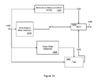
- FIG. 14 illustrates shows a process for detecting a solid edge and non-solid edge for use in a binary to contone conversion process.
- grayscale image is defined as a digital image with more than 1 bit per pixel (multi-bit depth), having 2 n “levels” of intensity wherein n is the number of bits-per-pixel; e.g., 4 bits-per-pixel corresponds to 16 levels of intensity.
- Grayscale image data may also include “contone” image data or “continuous tone” image data.
- binary image is defined as a digital image with only 1 bit per pixel (single-bit depth). As such, pixels of binary images are limited to only two levels: 0 and 1.
- Grayscale images can be combined with any number of other images to represent multiple separation images.
- each grayscale image may represent one of four separations of a CMYK color model (C, M, Y, K).
- the halftone process renders intensity or lightness levels by converting an incoming grayscale image to a halftoned image.
- a halftone representation is only an approximation of an original image.
- a grayscale image of 8 bits-per-pixel can be halftoned (using multi-level or grayscale halftoning method) to a grayscale image of 4 bits-per-pixel (16 levels).
- An example of halftoning is set forth in U.S. Pat. No. 4,149,194, which content is hereby incorporated by reference.
- Compression is the coding of data to minimize the space needed to store said data.
- the compression of images is motivated by the economic and logistic needs to conserve space in storage media and to save bandwidth in communication.
- the compression process may be referred to as “lossless” (also referred to as “reversible” or “noiseless”) if the reconstructed image is identical to the original.
- the compression process may be referred to as “lossy” compression (also referred to as “irreversible” or “noisy”) if the reconstructed image is not identical to the original (usually of inferior quality, though not necessarily visually detectable).
- a hard edge is an edge where the transition between the “dark” and “light” areas or pixels is very sharp, usually within the space of a single pixel. Such edges are characteristic of graphic images or text.
- a fuzzy edge is an edge where the transition between two levels (“dark” and “light”) on either side of the image is more gradual. These edges are characteristic of continuous tone (contone) originals such as photographs.
- FIG. 1 illustrates a process that generates inferred edge information from a binary image and uses the inferred information to aid the conversion of a binary image to a contone image.
- the process examines each pixel in the image to determine if it is part of either a hard edge or a fuzzy edge.
- the examination process not only identifies the type of edge, if present, but also identifies additional information related to the orientation of the edge.
- a binary image is received.
- An iterative process is started, at step S 104 , for each pixel in the image.
- a neighborhood around the pixel is first examined, at step S 106 , to see if a hard edge is present. If a hard edge is present, the pixel value is simply multiplied by 255, at step S 108 , to generate a contone value.
- the pixel neighborhood is examined, at step S 110 , to see if a fuzzy edge is present.
- the examination process also identifies the orientation of the edge in the window if it is present. If a fuzzy edge is identified, the pixel is converted to a contone value by an adaptive filter, at step S 1112 .
- the filtering, at step S 112 uses information about the type and edge orientation to choose a filter.
- the pixel is converted to a contone value, at step S 114 , by a filter which uses the neighborhood information.
- the process now checks to see if all pixels have been processed, at step S 116 , and if not the next pixel is selected, at step S 118 , and the process repeats. In this fashion, the entire image is processed and converted to a contone image.
- FIG. 2 shows the process of identifying hard edges in a binary image.
- the process in FIG. 2 examines the binary image using a 5 ⁇ 5 window centered on the pixel of interest. It is to be understood that the process in FIG. 2 is repeated for each pixel in the image. A variety of morphological operations are performed on the subset of the image that falls in the window.
- the number of pixel clusters is determined.
- pixels are part of a cluster if the pixels are connected in a “4-connection” sense.
- a “4-connection” sense means that only those pixels that are horizontally or vertically aligned with the pixel of interest are considered to be connected to it.
- step S 204 the number of clusters is checked. If the number of clusters is not greater than 5, there is no hard edge, and the process exits via step S 222 , marking the status as “ 0 ” indicating that the current pixel is not part of a hard edge.
- step S 206 checks for the potential for a zaggy edge.
- a zaggy edge is one where there are pixels sticking out from the edge, as opposed to a smooth edge. This check is made by seeing if there are any pixels sticking out along either the rows or columns.
- step S 208 If there is a zaggy edge present at step S 208 , the process exits via step S 222 with edge status of “ 0 .” If no zaggy edge is detected at step S 208 , step S 210 determines if there are any holes in the 5 ⁇ 5 window. In this check, pixels are considered connected in the “8-connection” sense, wherein both diagonally adjacent pixels are considered connected as well as horizontally and vertically adjacent ones as in the 4-connection sense.
- step S 212 If there are any holes detected at step S 212 , there is no hard edge present and the process exits via step S 222 with edge status “ 0 .”
- step S 214 the number of single pixel clusters is calculated. If such a condition exists at step S 216 , the pixel of interest is part of a hard edge, and the process exits via step S 224 with an edge status of “ 1 .”
- the image must be examined to see if it is possible that the edge is of the opposite sense—that is, for example, if the pixel is a light pixel at a light to dark transition or if it is a dark pixel in a light to dark transition.
- step S 218 the sense of the video is checked at step S 218 to see if both senses have been checked. If both senses have not been checked at step S 218 , the video is reversed at step S 220 and control proceeds back to step S 202 to repeat the checks with the reversed video sense.
- step S 218 If, however, both video senses have been checked at step S 218 , control exits via step S 226 where the edge status is marked as “ 0 .”
- FIG. 3 Before the process described in FIG. 2 is complete, a final check is made to eliminate potential artifacts from the process of FIG. 2 by a final filtering process.
- the final filtering process is illustrated in FIG. 3 .
- a three tag bit pattern which is output from the process of FIG. 2 , is checked.
- the three tag bit pattern is “101,” at step S 310 the three tag bit pattern is changed to “111.” If the three tag bit pattern is not “101,” at step S 306 , the three tag bit pattern is checked to see if the three tag bit pattern is “010.” If the three tag bit pattern is “010,” at step S 312 the pattern is changed to “000.”
- the previous window had only one object in it, the value of the tag bit at position i-1 is changed to “0” at step S 314 .
- the presence of a fuzzy edge is detected.
- certain patterns of pixels around the pixel can be analyzed.
- a 5 ⁇ 5 window can be used to identify the presence of a fuzzy edge and further differentiate between the various types of edges that may be present.
- seven separate cases or patterns can be used to clearly identify fuzzy edges in images. An example of these seven cases will be considered in describing the process illustrated in FIG. 12 .
- FIGS. 4 through 11 show various patterns that typify different classes of fuzzy edges. Each of these Figures illustrates a case where a pixel of interest, indicated by “C,” is actually part of the edge.
- pixels having a value of “1” are shown as shaded, while those pixels having a value of “0” are shown as clear.
- FIGS. 4 through 11 can be considered as hierarchical, with the patterns shown in FIG. 4 being of a higher priority than the patterns shown in FIG. 5 and so on.
- the process is considered in order from highest priority to lowest, and thus, if a particular case is found to apply, the lower priority cases are not considered.
- FIG. 4 shows the four patterns where the pixel is part of an edge such that the edge is the corner of an object that protrudes into the 5 ⁇ 5 window.
- Each of the patterns in FIG. 4 differs only in the orientation of the corner with respect to the 5 ⁇ 5 window.
- FIG. 5 shows the four patterns where the pixel might be part of a horizontal or vertical edge. Again, there are four possible patterns depending on which side of the 5 ⁇ 5 window the edge is located. Since the process is only interested in those cases where the pixel of interest lies on the edge, the “1” or “0” pixels cover two of the five rows or columns depending on which side the edge is located.
- FIG. 6 shows the four patterns where the edge is along a 45 degree diagonal through the center of the 5 ⁇ 5 window. All four possible 45 degree orientations are shown.
- FIG. 7 shows those patterns where the edge consists of a thin (3 pixel wide) line through the center of the 5 ⁇ 5 window. Both the patterns where the edge is dark (“1” pixels) and light (“0” pixels) are considered as well as both orientations are shown.
- FIG. 8 shows those patterns where the edge consists of a thin (3 pixel wide) line on a 45 degree diagonal through the center of the 5 ⁇ 5 window. Both the patterns where the edge is dark (“1” pixels) and light (“0” pixels) are considered as well as both orientations are shown.
- FIG. 9 shows the patterns where the edge consists of a 3 ⁇ 3 square centered on the 5 ⁇ 5 window. The pattern is shown where the square is “1” pixels, and the pattern where the square is “0” pixels is shown.
- FIG. 10 shows corner patterns where the pixel in the center is the point of a corner that protrudes into the window from one of the four sides.
- FIG. 11 shows the four patterns where the center pixel is part of an edge consisting of one of the horizontal, vertical or 45 degree lines through the center of the 5 ⁇ 5 window.
- step S 1202 the process begins at step S 1202 where the pattern/number of the pixels in a 5 ⁇ 5 window is considered.
- the pixel count for the 5 ⁇ 5 window is computed at step S 1204 , which is the number of pixels that identify one of the patterns, as illustrated in FIGS. 4-11 , under consideration.
- step S 1206 the sense of the center pixel is checked. If the center pixel is a “ 1 ,” control passes to steps S 1222 and/or S 1224 which determine if the pixel is part of a dark edge and if so sets the status bits appropriately at step S 1226 . These steps (S 1222 and/or S 1224 ) check to see that one half of the pattern is a zero and that the other half is above a threshold whose value is dependent on the particular case being checked.
- the values of the threshold may depend upon the imaging path characteristics. If the imaging path is noisy, a higher threshold may be used.
- step S 1206 If, at step S 1206 , the center pixel is a “ 0 ,” another set of tests are performed. First a check is made, at step S 1208 , to see if the edge count exceeds a threshold 2. If the count exceeds the threshold, control passes to the tests in steps S 1210 and/or S 1212 , where a check is made to see if the pixel is part of a fuzzy edge and on the dark side of the edge, and if so, the process sets the status bits appropriately at step S 1214 .
- step S 1228 a check is made to see if an edge has been detected. If step S 1228 determines that an edge has been detected, the fuzzy edge detection process is done and the process exits with the appropriate edge information for the other parts of the processing.
- the non-solid detection process can produce two types of output.
- One type of output, which the non-solid detection process can produce is a binary tag bit that represents whether the current pixel is an edge or not.
- the other type of output, which the non-solid detection process can produce is an edge code that indicates which partition group can be used for restoration, and within the group, which side of the two clusters of pixels can be used to determine the count.
- FIG. 13 illustrates a block diagram showing a binary to contone conversion module which can be utilized in for scanned and PCL/Tiff jobs (binary data) or PostScript jobs (four-bit data).
- the contone conversion module includes solid edge/area detection circuit 1315 , a non-solid or fuzzy edge detection circuit 1320 , a binary to contone conversion circuit (multiplier) 1330 , an adaptive (fuzzy) filtering circuit 1335 , a multiplexer 1310 , a multiplexer 1345 , a contrast detection circuit 1325 , and a four-bit to contone conversion circuit 1340 .
- One-bit binary image data 1300 is fed into the solid edge/area detection circuit 1315 and multiplexer 1310 . If the job being rendered is a scanned and PCL/Tiff job (binary data), the multiplexer 1310 feds the one-bit binary image data 1300 to the non-solid or fuzzy edge detection circuit 1320 .
- the solid edge/area detection circuit 1315 analyzes a predetermined window of pixels to determine if the pixel in question is a non-fuzzy or hard edge. This detection process has been discussed above.
- the solid edge/area detection circuit 1315 feds a signal to the multiplexer 1345 wherein the signal corresponds to the state of the pixel in question being a non-fuzzy or hard edge.
- the contone conversion circuit (multiplier) 1330 produces eight-bit contone image data from the one-bit binary image data and feds the eight-bit contone image data to the multiplexer 1345 .
- the non-solid or fuzzy edge detection circuit 1320 analyzes a predetermined window of pixels to determine if the pixel in question is a fuzzy or soft edge. Based upon the analysis, the non-solid or fuzzy edge detection circuit 1320 outputs information to the adaptive (fuzzy) filtering circuit 1335 .
- the adaptive (fuzzy) filtering circuit 1335 utilizes the information to control a filter bank of the adaptive (fuzzy) filtering circuit 1335 so as to perform an adaptive low pass filter upon the input image to produce eight-bit image data.
- the eight-bit image data is fed to the multiplexer 1345 .
- the four-bit image data 1305 is fed to the contrast detection circuit 1325 and multiplexer 1310 .
- the multiplexer 1310 feds the four-bit image data 1305 to the non-solid or fuzzy edge detection circuit 1320 .
- the contrast detection circuit 1325 determines, in a conventional manner, the contrast characteristics of the input data 1305 and feds this information to the four-bit to contone conversion circuit 1340 .
- the four-bit to contone conversion circuit 1340 utilizes the contrast information, in a conventional manner, to convert the four-bit data into eight-bit contone data and feds the eight-bit contone data to the multiplexer 1345 .
- the multiplexer 1345 outputs either the eight-bit contone image data from the contone conversion circuit (multiplier) 1330 or the eight-bit image data from the adaptive (fuzzy) filtering circuit 1335 based upon the state of the signal from the solid edge/area detection circuit 1315 . More specifically, the multiplexer 1345 outputs the eight-bit contone image data from the contone conversion circuit (multiplier) 1330 when the solid edge/area detection circuit 1315 detects a non-fuzzy or hard edge. On the other hand, the multiplexer 1345 outputs the eight-bit image data from the adaptive (fuzzy) filtering circuit 1335 when the solid edge/area detection circuit 1315 does not detect a non-fuzzy or hard edge.
- the multiplexer 1345 outputs either the eight-bit contone image data from the four-bit to contone conversion circuit 1340 or the eight-bit image data from the adaptive (fuzzy) filtering circuit 1335 based upon the state of the signal from the non-solid or fuzzy edge detection circuit 1320 . More specifically, the multiplexer 1345 outputs the eight-bit contone image data from the four-bit to contone conversion circuit 1340 when non-solid or fuzzy edge detection circuit 1320 does not detect a fuzzy or soft edge. On the other hand, the multiplexer 1345 outputs the eight-bit image data from the adaptive (fuzzy) filtering circuit 1335 when the non-solid or fuzzy edge detection circuit 1320 detects a fuzzy or soft edge.
- the output eight-bit image data from the multiplexer 1345 can be further processed by processing circuit 1350 to produce processed image data 1355 .
- the binary to contone conversion circuit (multiplier) 1420 converts the one-bit binary image data 1400 to eight-bit contone image data 1425 .
- the eight-bit image data 1445 and eight-bit contone image data 1425 are fed to multiplexer 1450 . If the solid edge/area detection circuit 1410 determines that the pixel in question is a non-fuzzy or hard edge, signal 1415 causes multiplexer 1450 to select eight-bit contone image data 1425 as the output data 1455 . If the solid edge/area detection circuit 1410 determines that the pixel in question is not a non-fuzzy or hard edge, signal 1415 causes multiplexer 1450 to select eight-bit image data 1445 as the output data 1455 . Thus, depending on the solid edge detection result, the output image data 1455 is either untouched solid area ( 1425 ) or the low pass filtered result ( 1445 ).
- FIG. 14 illustrates a block diagram showing a binary to contone conversion module utilizing both solid edge detection and fuzzy edge detection.
- the binary to contone conversion module includes solid edge/area detection circuit 1410 , a non-solid or fuzzy edge detection circuit 1430 , a binary to contone conversion circuit (multiplier) 1420 , an adaptive filtering circuit 1440 , and a multiplexer 1450 .
- One-bit binary image data 1400 is fed into the solid edge/area detection circuit 1410 , a non-solid or fuzzy edge detection circuit 1430 , binary to contone conversion circuit (multiplier) 1420 , and adaptive filtering circuit 1440 .
- the solid edge/area detection circuit 1410 analyzes a predetermined window of pixels to determine if the pixel in question is a non-fuzzy or hard edge. This detection process has been discussed above.
- the solid edge/area detection circuit 1410 feds a signal 1415 to the multiplexer 1450 wherein the signal corresponds to the state of the pixel in question being a non-fuzzy or hard edge.
- the non-solid or fuzzy edge detection circuit 1430 analyzes a predetermined window of pixels to determine if the pixel in question is a fuzzy or soft edge. Based upon the analysis, the non-solid or fuzzy edge detection circuit 1430 outputs a five-bit tag which is fed to the adaptive filtering circuit 1440 .
- the adaptive filtering circuit 1440 utilizes the five-bit tag to control the filter bank of the adaptive filtering circuit 1440 so as to perform an adaptive low pass filter upon the input image to produce eight-bit image data 1445 .
- the binary to contone conversion circuit (multiplier) 1420 converts the one-bit binary image data 1400 to eight-bit contone image data 1425 .
- the eight-bit image data 1445 and eight-bit contone image data 1425 are fed to multiplexer 1450 . If the solid edge/area detection circuit 1410 determines that the pixel in question is a non-fuzzy or hard edge, signal 1415 causes multiplexer 1450 to select eight-bit contone image data 1425 as the output data 1455 . If the solid edge/area detection circuit 1410 determines that the pixel in question is not a non-fuzzy or hard edge, signal 1415 causes multiplexer 1450 to select eight-bit image data 1445 as the output data 1455 . Thus, depending on the solid edge detection result, the output image data 1455 is either untouched solid area ( 1425 ) or the low pass filtered result ( 1445 ).
- the system of FIG. 14 is for a single channel of binary image data.
- the process is readily applicable to multiple channels of binary image data.
- cross channel information can be utilized to improve edge detection and therefore the restoration of the contone image data from the binary image data.
- the solid edge detection information can be fed into the fuzzy edge detection module to enable more intelligent fuzzy edge detection.
Abstract
Description
Claims (1)
Priority Applications (1)
| Application Number | Priority Date | Filing Date | Title |
|---|---|---|---|
| US12/197,348 US9460491B2 (en) | 2008-08-25 | 2008-08-25 | Method for binary to contone conversion with non-solid edge detection |
Applications Claiming Priority (1)
| Application Number | Priority Date | Filing Date | Title |
|---|---|---|---|
| US12/197,348 US9460491B2 (en) | 2008-08-25 | 2008-08-25 | Method for binary to contone conversion with non-solid edge detection |
Publications (2)
| Publication Number | Publication Date |
|---|---|
| US20100046856A1 US20100046856A1 (en) | 2010-02-25 |
| US9460491B2 true US9460491B2 (en) | 2016-10-04 |
Family
ID=41696468
Family Applications (1)
| Application Number | Title | Priority Date | Filing Date |
|---|---|---|---|
| US12/197,348 Active 2033-03-29 US9460491B2 (en) | 2008-08-25 | 2008-08-25 | Method for binary to contone conversion with non-solid edge detection |
Country Status (1)
| Country | Link |
|---|---|
| US (1) | US9460491B2 (en) |
Cited By (1)
| Publication number | Priority date | Publication date | Assignee | Title |
|---|---|---|---|---|
| US11535029B2 (en) | 2018-04-25 | 2022-12-27 | Hewlett-Packard Development Company, L.P. | Printing modes to print an outline and a fill area |
Families Citing this family (6)
| Publication number | Priority date | Publication date | Assignee | Title |
|---|---|---|---|---|
| US7773254B2 (en) * | 2005-11-10 | 2010-08-10 | Xerox Corporation | Method and system for improved copy quality in a multifunction reprographic system |
| US7561747B2 (en) * | 2005-12-23 | 2009-07-14 | Xerox Corporation | Image data processing system and method |
| US8797601B2 (en) | 2012-03-22 | 2014-08-05 | Xerox Corporation | Method and system for preserving image quality in an economy print mode |
| US9275467B2 (en) * | 2012-03-29 | 2016-03-01 | Analog Devices, Inc. | Incremental contour-extraction scheme for binary image segments |
| JP6477264B2 (en) * | 2015-06-01 | 2019-03-06 | 株式会社リコー | Image forming apparatus, image forming method, and image forming program |
| TWI729416B (en) * | 2019-06-19 | 2021-06-01 | 通寶半導體設計股份有限公司 | Method of optimizing printing |
Citations (75)
| Publication number | Priority date | Publication date | Assignee | Title |
|---|---|---|---|---|
| US4958236A (en) | 1987-06-11 | 1990-09-18 | Canon Kabushiki Kaisha | Image processing method and apparatus therefor |
| US5008950A (en) | 1987-01-22 | 1991-04-16 | Canon Kabushiki Kaisha | Image processing method and apparatus for error-dispersion digitization without moire or spurious stripe formation |
| US5065255A (en) | 1989-06-27 | 1991-11-12 | Fuji Photo Film Co., Ltd. | Method of and apparatus for smoothing an image having a periodic pattern |
| US5293430A (en) | 1991-06-27 | 1994-03-08 | Xerox Corporation | Automatic image segmentation using local area maximum and minimum image signals |
| US5323232A (en) | 1990-08-01 | 1994-06-21 | Matsushita Electric Industrial Co., Ltd. | Filter device for decimation and interpolation of chrominance components of a video signal |
| US5347599A (en) | 1991-06-14 | 1994-09-13 | Matsushita Electric Industrial Co., Ltd. | Adaptive interpolation method and apparatus using correlation detection |
| GB2291308A (en) | 1994-07-14 | 1996-01-17 | Samsung Electronics Co Ltd | Error diffusion image encoding |
| US5572606A (en) | 1985-10-18 | 1996-11-05 | Canon Kabushiki Kaisha | Image information processing method and apparatus therefor with multi-level data capability |
| JPH0951431A (en) | 1995-08-02 | 1997-02-18 | Fuji Xerox Co Ltd | Image processing unit |
| US5617216A (en) | 1993-07-07 | 1997-04-01 | Nec Corporation | Image formation device with binary/halftone pixel determination |
| US5617459A (en) | 1994-07-12 | 1997-04-01 | U.S. Philips Corporation | Method of processing images in order automatically to detect key points situated on the contour of an object and device for implementing this method |
| US5754710A (en) | 1993-08-06 | 1998-05-19 | Fuji Xerox Co., Ltd. | Image resolution conversion method and appratus thereof |
| US5805724A (en) * | 1996-09-24 | 1998-09-08 | Xerox Corporation | Method and system for hybrid error diffusion processing of image information using dynamic screens based on brightness/darkness settings |
| US5818964A (en) | 1994-12-27 | 1998-10-06 | Texas Instruments Incorporated | Method and apparatus for selecting an adaptive filter for image data |
| US5850474A (en) | 1996-07-26 | 1998-12-15 | Xerox Corporation | Apparatus and method for segmenting and classifying image data |
| US5898821A (en) * | 1997-01-21 | 1999-04-27 | Xerox Corporation | Printing system with halftone substitution capability |
| WO1999030547A2 (en) | 1997-12-08 | 1999-06-17 | Intel Corporation | A new edge-detection based noise removal algorithm |
| US5959290A (en) | 1998-01-08 | 1999-09-28 | Xerox Corporation | Image input device and method for providing scanning artifact detection |
| US6020979A (en) | 1998-03-23 | 2000-02-01 | Xerox Corporation | Method of encoding high resolution edge position information in continuous tone image information |
| US6097503A (en) * | 1998-01-23 | 2000-08-01 | Adobe Systems Incorporated | Bi-level to contone data conversion |
| US6130966A (en) * | 1995-11-17 | 2000-10-10 | Fuji Xerox Co., Ltd. | Image processing system and method for converting an input N-valued (N>or-Z) image into an M-valued (M>N) image |
| US6181829B1 (en) * | 1998-01-21 | 2001-01-30 | Xerox Corporation | Method and system for classifying and processing of pixels of image data |
| US6259823B1 (en) | 1997-02-15 | 2001-07-10 | Samsung Electronics Co., Ltd. | Signal adaptive filtering method and signal adaptive filter for reducing blocking effect and ringing noise |
| US6275303B1 (en) | 1997-09-30 | 2001-08-14 | Brother Kogyo Kabushiki Kaisha | Method and system for processing multi-level tone value images including text, graphic images and continuous tone images by using halftoning technique |
| US6282325B1 (en) | 1997-07-04 | 2001-08-28 | Samsung Electronics Co., Ltd. | Image processing technique for binarizing an image scanned by a shuttle type scanner |
| US6285464B1 (en) | 1987-11-16 | 2001-09-04 | Canon Kabushiki Kaisha | Apparatus and method for producing a half-tone image |
| US6343159B1 (en) | 1998-12-23 | 2002-01-29 | Xerox Corporation | Method and apparatus for modeling and reconstruction of halftoned images |
| US6427030B1 (en) | 1994-08-03 | 2002-07-30 | Xerox Corporation | Method and system for image conversion utilizing dynamic error diffusion |
| US20020126912A1 (en) | 2000-12-26 | 2002-09-12 | Rouvellou Laurent Jean Marie | Data processing method |
| US20020140983A1 (en) | 2001-03-27 | 2002-10-03 | Fuji Photo Film Co., Ltd. | Image conversion method, image conversion apparatus, and image conversion program storage medium |
| US20020159096A1 (en) | 2001-03-29 | 2002-10-31 | Sharp Laboratories Of America, Inc. | Adaptive image filtering based on a distance transform |
| US6477282B1 (en) | 1997-12-16 | 2002-11-05 | Sharp Kabushiki Kaisha | Image forming device |
| US20020181797A1 (en) | 2001-04-02 | 2002-12-05 | Eastman Kodak Company | Method for improving breast cancer diagnosis using mountain-view and contrast-enhancement presentation of mammography |
| US20020191857A1 (en) | 2001-05-14 | 2002-12-19 | Macy William W. | Inverse halftoning process |
| US20020196467A1 (en) | 2001-06-22 | 2002-12-26 | Marc Delhoune | Page composition in an image reproduction system using segmented page elements |
| US20030007687A1 (en) | 2001-07-05 | 2003-01-09 | Jasc Software, Inc. | Correction of "red-eye" effects in images |
| US20030043210A1 (en) | 2001-09-04 | 2003-03-06 | Hanks Darwin Mitchel | System and method for generating high-resolution images via resolution-limited devices |
| US20030091222A1 (en) | 2001-11-14 | 2003-05-15 | Eastman Kodak Company | Method for contrast-enhancement of digital portal images |
| US20030090729A1 (en) | 2001-10-01 | 2003-05-15 | Xerox Corporation | Rank-order error diffusion image processing |
| US6594401B1 (en) | 1999-10-20 | 2003-07-15 | Xerox Corporation | Detection and elimination of scanning artifacts |
| US20030133610A1 (en) | 2001-12-20 | 2003-07-17 | Xerox Corporation | Block level analysis of segmentation tags |
| US6606420B1 (en) | 1999-10-25 | 2003-08-12 | Xerox Corporation | Method and apparatus for digital image darkness control in saturated image structures |
| US6608701B1 (en) | 1999-07-07 | 2003-08-19 | Xerox Corporation | Compact high addressability rendering |
| US20030193680A1 (en) | 1999-05-18 | 2003-10-16 | Karidi Ron J. | Image reconstruction architecture |
| US6683702B1 (en) | 1999-07-07 | 2004-01-27 | Xerox Corporation | Compact-dot reproduction of scanned halftone screens |
| US20040066538A1 (en) | 2002-10-04 | 2004-04-08 | Rozzi William A. | Conversion of halftone bitmaps to continuous tone representations |
| US20040114814A1 (en) | 2002-12-13 | 2004-06-17 | Martin Boliek | Layout objects as image layers |
| US6771832B1 (en) | 1997-07-29 | 2004-08-03 | Panasonic Communications Co., Ltd. | Image processor for processing an image with an error diffusion process and image processing method for processing an image with an error diffusion process |
| US20040175037A1 (en) | 2003-03-06 | 2004-09-09 | Guleryuz Onur G. | Method and apparatus for segmentation of compound documents having low resolution halftones |
| US6873437B1 (en) | 1999-10-14 | 2005-03-29 | Matsushita Electric Industrial Co., Ltd. | Image processing method and image processing apparatus |
| US6920252B2 (en) | 2000-12-26 | 2005-07-19 | Koninklijke Philips Electronics N.V. | Data processing method |
| US20050163374A1 (en) | 2004-01-28 | 2005-07-28 | Ferman A. M. | Methods and systems for automatic detection of continuous-tone regions in document images |
| US20050206948A1 (en) | 2004-03-16 | 2005-09-22 | Fuji Xerox Co., Ltd. | Image formation assistance device, image formation assistance method and image formation assistance system |
| EP1583064A1 (en) | 2003-12-26 | 2005-10-05 | Matsushita Electric Industrial Co., Ltd. | Image signal processing apparatus and image signal processing method |
| US20050259886A1 (en) | 2004-05-20 | 2005-11-24 | Jizhang Shan | Methods and systems for locally adaptive image processing filters |
| US20050270582A1 (en) | 2004-06-08 | 2005-12-08 | Fuji Xerox Co., Ltd. | Image processing apparatus, image processing method, and image processing program |
| US6975434B1 (en) | 1999-10-05 | 2005-12-13 | Hewlett-Packard Development Company, L.P. | Method and apparatus for scanning oversized documents |
| US20060077489A1 (en) | 2004-08-20 | 2006-04-13 | Xerox Corporation | Uniformity compensation in halftoned images |
| US7043080B1 (en) | 2000-11-21 | 2006-05-09 | Sharp Laboratories Of America, Inc. | Methods and systems for text detection in mixed-context documents using local geometric signatures |
| US20060115182A1 (en) | 2004-11-30 | 2006-06-01 | Yining Deng | System and method of intensity correction |
| US20060132847A1 (en) | 2004-12-17 | 2006-06-22 | Xerox Corporation | Systems and methods for rank-order error diffusion image processing |
| US20060132850A1 (en) | 2004-12-22 | 2006-06-22 | Xerox Corporation | Systems and methods for improved line edge quality |
| US20060232798A1 (en) | 2005-04-13 | 2006-10-19 | Xerox Corporation. | Blended error diffusion and adaptive quantization |
| US20060257045A1 (en) * | 2005-05-11 | 2006-11-16 | Xerox Corporation | Method and system for extending binary image data to contone image data |
| US20070053003A1 (en) | 2005-09-02 | 2007-03-08 | Xerox Corporation | Color management of halftoned images |
| US20070103731A1 (en) | 2005-11-07 | 2007-05-10 | Xerox Corporation | Method and system for generating contone encoded binary print data streams |
| US20070109602A1 (en) | 2005-11-17 | 2007-05-17 | Xerox Corporation | Method and system for improved copy quality in a multifunction reprographic system |
| US20070172149A1 (en) | 2006-01-26 | 2007-07-26 | Xerox Corporation | System and method for boundary artifact elimination in parallel processing of large format images |
| US20070172148A1 (en) | 2006-01-25 | 2007-07-26 | Atalasoft, Inc. | Method of image analysis using sparse hough transform |
| US20070258101A1 (en) | 2005-11-10 | 2007-11-08 | Xerox Corporation | Method and system for improved copy quality in a multifunction reprographic system |
| US20080049238A1 (en) | 2006-08-28 | 2008-02-28 | Xerox Corporation | Method and system for automatic window classification in a digital reprographic system |
| US7352490B1 (en) * | 2006-09-13 | 2008-04-01 | Xerox Corporation | Method and system for generating contone encoded binary print data streams |
| US7372992B2 (en) | 2003-10-31 | 2008-05-13 | Ricoh Co., Ltd. | Image data processing machine |
| US7440139B2 (en) | 2005-01-13 | 2008-10-21 | Xerox Corporation | Systems and methods for controlling a tone reproduction curve using error diffusion |
| US20100232706A1 (en) * | 2009-03-12 | 2010-09-16 | Qualcomm Incorporated | Response to detection of blur in an image |
Family Cites Families (2)
| Publication number | Priority date | Publication date | Assignee | Title |
|---|---|---|---|---|
| US5296430A (en) * | 1989-09-20 | 1994-03-22 | Idemitsu Petrochemical Company, Ltd. | Method for the preparation of a stabilized catalyst for the polymerization of olefins |
| US6550515B2 (en) * | 2000-12-04 | 2003-04-22 | Edward Lavelle | Rolled material dispensing apparatus |
-
2008
- 2008-08-25 US US12/197,348 patent/US9460491B2/en active Active
Patent Citations (88)
| Publication number | Priority date | Publication date | Assignee | Title |
|---|---|---|---|---|
| US5572606A (en) | 1985-10-18 | 1996-11-05 | Canon Kabushiki Kaisha | Image information processing method and apparatus therefor with multi-level data capability |
| US5008950A (en) | 1987-01-22 | 1991-04-16 | Canon Kabushiki Kaisha | Image processing method and apparatus for error-dispersion digitization without moire or spurious stripe formation |
| US4958236A (en) | 1987-06-11 | 1990-09-18 | Canon Kabushiki Kaisha | Image processing method and apparatus therefor |
| US6285464B1 (en) | 1987-11-16 | 2001-09-04 | Canon Kabushiki Kaisha | Apparatus and method for producing a half-tone image |
| US5065255A (en) | 1989-06-27 | 1991-11-12 | Fuji Photo Film Co., Ltd. | Method of and apparatus for smoothing an image having a periodic pattern |
| US5323232A (en) | 1990-08-01 | 1994-06-21 | Matsushita Electric Industrial Co., Ltd. | Filter device for decimation and interpolation of chrominance components of a video signal |
| US5347599A (en) | 1991-06-14 | 1994-09-13 | Matsushita Electric Industrial Co., Ltd. | Adaptive interpolation method and apparatus using correlation detection |
| US5293430A (en) | 1991-06-27 | 1994-03-08 | Xerox Corporation | Automatic image segmentation using local area maximum and minimum image signals |
| US5617216A (en) | 1993-07-07 | 1997-04-01 | Nec Corporation | Image formation device with binary/halftone pixel determination |
| US5754710A (en) | 1993-08-06 | 1998-05-19 | Fuji Xerox Co., Ltd. | Image resolution conversion method and appratus thereof |
| US5617459A (en) | 1994-07-12 | 1997-04-01 | U.S. Philips Corporation | Method of processing images in order automatically to detect key points situated on the contour of an object and device for implementing this method |
| GB2291308A (en) | 1994-07-14 | 1996-01-17 | Samsung Electronics Co Ltd | Error diffusion image encoding |
| US6427030B1 (en) | 1994-08-03 | 2002-07-30 | Xerox Corporation | Method and system for image conversion utilizing dynamic error diffusion |
| US5818964A (en) | 1994-12-27 | 1998-10-06 | Texas Instruments Incorporated | Method and apparatus for selecting an adaptive filter for image data |
| JPH0951431A (en) | 1995-08-02 | 1997-02-18 | Fuji Xerox Co Ltd | Image processing unit |
| US6130966A (en) * | 1995-11-17 | 2000-10-10 | Fuji Xerox Co., Ltd. | Image processing system and method for converting an input N-valued (N>or-Z) image into an M-valued (M>N) image |
| US5850474A (en) | 1996-07-26 | 1998-12-15 | Xerox Corporation | Apparatus and method for segmenting and classifying image data |
| US6240205B1 (en) | 1996-07-26 | 2001-05-29 | Xerox Corporation | Apparatus and method for segmenting and classifying image data |
| US5805724A (en) * | 1996-09-24 | 1998-09-08 | Xerox Corporation | Method and system for hybrid error diffusion processing of image information using dynamic screens based on brightness/darkness settings |
| US5898821A (en) * | 1997-01-21 | 1999-04-27 | Xerox Corporation | Printing system with halftone substitution capability |
| US6259823B1 (en) | 1997-02-15 | 2001-07-10 | Samsung Electronics Co., Ltd. | Signal adaptive filtering method and signal adaptive filter for reducing blocking effect and ringing noise |
| US6282325B1 (en) | 1997-07-04 | 2001-08-28 | Samsung Electronics Co., Ltd. | Image processing technique for binarizing an image scanned by a shuttle type scanner |
| US6771832B1 (en) | 1997-07-29 | 2004-08-03 | Panasonic Communications Co., Ltd. | Image processor for processing an image with an error diffusion process and image processing method for processing an image with an error diffusion process |
| US6275303B1 (en) | 1997-09-30 | 2001-08-14 | Brother Kogyo Kabushiki Kaisha | Method and system for processing multi-level tone value images including text, graphic images and continuous tone images by using halftoning technique |
| US6229578B1 (en) | 1997-12-08 | 2001-05-08 | Intel Corporation | Edge-detection based noise removal algorithm |
| WO1999030547A2 (en) | 1997-12-08 | 1999-06-17 | Intel Corporation | A new edge-detection based noise removal algorithm |
| US6477282B1 (en) | 1997-12-16 | 2002-11-05 | Sharp Kabushiki Kaisha | Image forming device |
| US5959290A (en) | 1998-01-08 | 1999-09-28 | Xerox Corporation | Image input device and method for providing scanning artifact detection |
| US6181829B1 (en) * | 1998-01-21 | 2001-01-30 | Xerox Corporation | Method and system for classifying and processing of pixels of image data |
| US6097503A (en) * | 1998-01-23 | 2000-08-01 | Adobe Systems Incorporated | Bi-level to contone data conversion |
| US6020979A (en) | 1998-03-23 | 2000-02-01 | Xerox Corporation | Method of encoding high resolution edge position information in continuous tone image information |
| US6343159B1 (en) | 1998-12-23 | 2002-01-29 | Xerox Corporation | Method and apparatus for modeling and reconstruction of halftoned images |
| US20030193680A1 (en) | 1999-05-18 | 2003-10-16 | Karidi Ron J. | Image reconstruction architecture |
| US6608701B1 (en) | 1999-07-07 | 2003-08-19 | Xerox Corporation | Compact high addressability rendering |
| US6683702B1 (en) | 1999-07-07 | 2004-01-27 | Xerox Corporation | Compact-dot reproduction of scanned halftone screens |
| US6975434B1 (en) | 1999-10-05 | 2005-12-13 | Hewlett-Packard Development Company, L.P. | Method and apparatus for scanning oversized documents |
| US6873437B1 (en) | 1999-10-14 | 2005-03-29 | Matsushita Electric Industrial Co., Ltd. | Image processing method and image processing apparatus |
| US6594401B1 (en) | 1999-10-20 | 2003-07-15 | Xerox Corporation | Detection and elimination of scanning artifacts |
| US6606420B1 (en) | 1999-10-25 | 2003-08-12 | Xerox Corporation | Method and apparatus for digital image darkness control in saturated image structures |
| US7043080B1 (en) | 2000-11-21 | 2006-05-09 | Sharp Laboratories Of America, Inc. | Methods and systems for text detection in mixed-context documents using local geometric signatures |
| US6920252B2 (en) | 2000-12-26 | 2005-07-19 | Koninklijke Philips Electronics N.V. | Data processing method |
| US20020126912A1 (en) | 2000-12-26 | 2002-09-12 | Rouvellou Laurent Jean Marie | Data processing method |
| US20020140983A1 (en) | 2001-03-27 | 2002-10-03 | Fuji Photo Film Co., Ltd. | Image conversion method, image conversion apparatus, and image conversion program storage medium |
| US20020159096A1 (en) | 2001-03-29 | 2002-10-31 | Sharp Laboratories Of America, Inc. | Adaptive image filtering based on a distance transform |
| US20020181797A1 (en) | 2001-04-02 | 2002-12-05 | Eastman Kodak Company | Method for improving breast cancer diagnosis using mountain-view and contrast-enhancement presentation of mammography |
| US20020191857A1 (en) | 2001-05-14 | 2002-12-19 | Macy William W. | Inverse halftoning process |
| US20020196467A1 (en) | 2001-06-22 | 2002-12-26 | Marc Delhoune | Page composition in an image reproduction system using segmented page elements |
| US20030007687A1 (en) | 2001-07-05 | 2003-01-09 | Jasc Software, Inc. | Correction of "red-eye" effects in images |
| US20030043210A1 (en) | 2001-09-04 | 2003-03-06 | Hanks Darwin Mitchel | System and method for generating high-resolution images via resolution-limited devices |
| US20030090729A1 (en) | 2001-10-01 | 2003-05-15 | Xerox Corporation | Rank-order error diffusion image processing |
| US7079289B2 (en) | 2001-10-01 | 2006-07-18 | Xerox Corporation | Rank-order error diffusion image processing |
| US20030091222A1 (en) | 2001-11-14 | 2003-05-15 | Eastman Kodak Company | Method for contrast-enhancement of digital portal images |
| US20030133610A1 (en) | 2001-12-20 | 2003-07-17 | Xerox Corporation | Block level analysis of segmentation tags |
| US7039232B2 (en) | 2001-12-20 | 2006-05-02 | Xerox Corporation | Block level analysis of segmentation tags |
| US20040066538A1 (en) | 2002-10-04 | 2004-04-08 | Rozzi William A. | Conversion of halftone bitmaps to continuous tone representations |
| US20040114814A1 (en) | 2002-12-13 | 2004-06-17 | Martin Boliek | Layout objects as image layers |
| US20040175037A1 (en) | 2003-03-06 | 2004-09-09 | Guleryuz Onur G. | Method and apparatus for segmentation of compound documents having low resolution halftones |
| US7372992B2 (en) | 2003-10-31 | 2008-05-13 | Ricoh Co., Ltd. | Image data processing machine |
| EP1583064A1 (en) | 2003-12-26 | 2005-10-05 | Matsushita Electric Industrial Co., Ltd. | Image signal processing apparatus and image signal processing method |
| US20050163374A1 (en) | 2004-01-28 | 2005-07-28 | Ferman A. M. | Methods and systems for automatic detection of continuous-tone regions in document images |
| US20050206948A1 (en) | 2004-03-16 | 2005-09-22 | Fuji Xerox Co., Ltd. | Image formation assistance device, image formation assistance method and image formation assistance system |
| US20050259886A1 (en) | 2004-05-20 | 2005-11-24 | Jizhang Shan | Methods and systems for locally adaptive image processing filters |
| EP1601184A1 (en) | 2004-05-20 | 2005-11-30 | OmniVision Technologies, Inc. | Methods and systems for locally adaptive image processing filters |
| US20050270582A1 (en) | 2004-06-08 | 2005-12-08 | Fuji Xerox Co., Ltd. | Image processing apparatus, image processing method, and image processing program |
| US7460272B2 (en) * | 2004-06-08 | 2008-12-02 | Fuji Xerox Co., Ltd. | Image processing apparatus, image processing method, and image processing program |
| US20060077489A1 (en) | 2004-08-20 | 2006-04-13 | Xerox Corporation | Uniformity compensation in halftoned images |
| US20060115182A1 (en) | 2004-11-30 | 2006-06-01 | Yining Deng | System and method of intensity correction |
| US7460276B2 (en) | 2004-12-17 | 2008-12-02 | Xerox Corporation | Systems and methods for rank-order error diffusion image processing |
| US20060132847A1 (en) | 2004-12-17 | 2006-06-22 | Xerox Corporation | Systems and methods for rank-order error diffusion image processing |
| US20060132850A1 (en) | 2004-12-22 | 2006-06-22 | Xerox Corporation | Systems and methods for improved line edge quality |
| US7440139B2 (en) | 2005-01-13 | 2008-10-21 | Xerox Corporation | Systems and methods for controlling a tone reproduction curve using error diffusion |
| US20060232798A1 (en) | 2005-04-13 | 2006-10-19 | Xerox Corporation. | Blended error diffusion and adaptive quantization |
| US20060257045A1 (en) * | 2005-05-11 | 2006-11-16 | Xerox Corporation | Method and system for extending binary image data to contone image data |
| US7787703B2 (en) * | 2005-05-11 | 2010-08-31 | Xerox Corporation | Method and system for extending binary image data to contone image data |
| US20070053003A1 (en) | 2005-09-02 | 2007-03-08 | Xerox Corporation | Color management of halftoned images |
| US20070103731A1 (en) | 2005-11-07 | 2007-05-10 | Xerox Corporation | Method and system for generating contone encoded binary print data streams |
| US7580569B2 (en) | 2005-11-07 | 2009-08-25 | Xerox Corporation | Method and system for generating contone encoded binary print data streams |
| US20100157374A1 (en) | 2005-11-10 | 2010-06-24 | Xerox Corporation | Method and system for improved copy quality in a multifunction reprographic system |
| US20070258101A1 (en) | 2005-11-10 | 2007-11-08 | Xerox Corporation | Method and system for improved copy quality in a multifunction reprographic system |
| US7773254B2 (en) | 2005-11-10 | 2010-08-10 | Xerox Corporation | Method and system for improved copy quality in a multifunction reprographic system |
| US8023150B2 (en) | 2005-11-10 | 2011-09-20 | Xerox Corporation | Method and system for improved copy quality by generating contone value based on pixel pattern and image context type around pixel of interest |
| US20070109602A1 (en) | 2005-11-17 | 2007-05-17 | Xerox Corporation | Method and system for improved copy quality in a multifunction reprographic system |
| US7869093B2 (en) | 2005-11-17 | 2011-01-11 | Xerox Corporation | Method and system for improved copy quality in a multifunction reprographic system |
| US20070172148A1 (en) | 2006-01-25 | 2007-07-26 | Atalasoft, Inc. | Method of image analysis using sparse hough transform |
| US20070172149A1 (en) | 2006-01-26 | 2007-07-26 | Xerox Corporation | System and method for boundary artifact elimination in parallel processing of large format images |
| US20080049238A1 (en) | 2006-08-28 | 2008-02-28 | Xerox Corporation | Method and system for automatic window classification in a digital reprographic system |
| US7352490B1 (en) * | 2006-09-13 | 2008-04-01 | Xerox Corporation | Method and system for generating contone encoded binary print data streams |
| US20100232706A1 (en) * | 2009-03-12 | 2010-09-16 | Qualcomm Incorporated | Response to detection of blur in an image |
Non-Patent Citations (14)
| Title |
|---|
| A Machine Translation of Japanese patent publication JP09-051431 cited in a Japanese Office Action dated Nov. 30, 2009 for JPA 2006-128283, Japanese counterpart application of U.S. Appl. No. 11/126,970, JP09-051431 published Feb. 1997. |
| Aghdasi, Farzin; Ward, Rahab K.; Reduction of Boundary Artifacts in Image Restoration, IEEE Transactions on Image Processing, vol. 5, No. 4, Apr. 1996, pp. 611-618. |
| An unofficial copy of the File History as of Oct. 5, 2010 for U.S. Pat. No. 7,773,254 (U.S. Appl. No. 11/272,182). |
| An Unofficial copy of the File History as of Oct. 7, 2010 for U.S. Pat. No. 7,352,490 (U.S. Appl. No. 11/531,572). |
| An unofficial copy of the File History for as of Aug. 16, 2010 U.S. Pat. No. 7,580,569 (U.S. Appl. No. 11/268,147). |
| An unofficial copy of the Prosecution History as of Aug. 16, 2010 for U.S. Appl. No. 11/126,970. |
| An unofficial copy of the Prosecution History as of Oct. 5, 2010 for U.S. Appl. No. 11/281,267. |
| An Unofficial copy of the Prosecution History as of Oct. 5, 2010 for U.S. Appl. No. 12/719,233. |
| An unofficial copy of the Prosecution History as of Oct. 7, 2010 for U.S. Appl. No. 11/467,584. |
| He, Z.; Chang, T.; Allebach, J.; Bouman C.; Boundary Stitching Algorithm for Parallel Implementation of Error Diffusion; Xerox Corporation, provided Nov. 8, 2008, 12 pages. |
| U.S. Appl. No. 11/281,267-An Unofficial Copy of the Prosecution History Between Oct. 6, 2010 and Jan. 31, 2012 and of U.S. Pat. No. 7,869,093 Issued Jan. 11, 2011; U.S. Appl. No. 11/281,267, filed Nov. 17, 2005, Published May 17, 2007, as US-2007-0109602-A1; Inventor: Francis Kapo Tse et al. |
| U.S. Appl. No. 12/719,233-An Unofficial Copy of the Prosecution History Between Oct. 6, 2010 and Jan. 31, 2012 for U.S. Pat. No. 8,023,150 Issued Sep. 20, 2011; U.S. Appl. No. 12/719,233, filed Mar. 8, 2010, Published Jun. 24, 2010, as US-2010-0157374-A1; Inventor: Ramesh Nagarajan et al. |
| Unofficial European Office Action Dated Oct. 15, 2009 for European Patent Application EP06113615.6 (Corresponding to U.S. Appl. No. 11/126,970). |
| Unofficial European Search Report dated Feb. 25, 2009 for European Patent Application 06113615.6. (Corresponding to U.S. Appl. No. 11/126,970). |
Cited By (1)
| Publication number | Priority date | Publication date | Assignee | Title |
|---|---|---|---|---|
| US11535029B2 (en) | 2018-04-25 | 2022-12-27 | Hewlett-Packard Development Company, L.P. | Printing modes to print an outline and a fill area |
Also Published As
| Publication number | Publication date |
|---|---|
| US20100046856A1 (en) | 2010-02-25 |
Similar Documents
| Publication | Publication Date | Title |
|---|---|---|
| US7580569B2 (en) | Method and system for generating contone encoded binary print data streams | |
| US7352490B1 (en) | Method and system for generating contone encoded binary print data streams | |
| US5339172A (en) | Apparatus and method for segmenting an input image in one of a plurality of modes | |
| US9460491B2 (en) | Method for binary to contone conversion with non-solid edge detection | |
| US6137907A (en) | Method and apparatus for pixel-level override of halftone detection within classification blocks to reduce rectangular artifacts | |
| US6941014B2 (en) | Method and apparatus for segmenting an image using a combination of image segmentation techniques | |
| EP1505821B1 (en) | Image processing apparatus, an image forming apparatus and an image processing method | |
| US7787703B2 (en) | Method and system for extending binary image data to contone image data | |
| US6766053B2 (en) | Method and apparatus for classifying images and/or image regions based on texture information | |
| US8503036B2 (en) | System and method of improving image quality in digital image scanning and printing by reducing noise in output image data | |
| US8023150B2 (en) | Method and system for improved copy quality by generating contone value based on pixel pattern and image context type around pixel of interest | |
| US20080049238A1 (en) | Method and system for automatic window classification in a digital reprographic system | |
| JP5541672B2 (en) | Apparatus, method, program | |
| US20030206307A1 (en) | Neutral pixel detection using color space feature vectors wherein one color space coordinate represents lightness | |
| CN101902549A (en) | Image processing apparatus and image processing method | |
| US7869093B2 (en) | Method and system for improved copy quality in a multifunction reprographic system | |
| JP2017175213A (en) | Manuscript type recognition device, image forming apparatus, manuscript type recognition method and program | |
| US9948824B2 (en) | Image compressing device, image forming apparatus, image compressing method, and recording medium | |
| US20090110313A1 (en) | Device for performing image processing based on image attribute | |
| KR100747916B1 (en) | Data embedding scheme for duplex color laser printer | |
| US7106901B2 (en) | Method and apparatus for image classification | |
| US5995658A (en) | Image processing device and image output device converting binary image into multi-valued image | |
| JP4501696B2 (en) | Image processing apparatus and program | |
| US6411735B1 (en) | Method and apparatus for distinguishing between noisy continuous tone document types and other document types to maintain reliable image segmentation | |
| JP4656457B2 (en) | Image processing system |
Legal Events
| Date | Code | Title | Description |
|---|---|---|---|
| AS | Assignment |
Owner name: XEROX CORPORATION,CONNECTICUT Free format text: ASSIGNMENT OF ASSIGNORS INTEREST;ASSIGNORS:BAI, YINGJUN;LI, XING;SIGNING DATES FROM 20080904 TO 20080905;REEL/FRAME:021512/0267 Owner name: XEROX CORPORATION, CONNECTICUT Free format text: ASSIGNMENT OF ASSIGNORS INTEREST;ASSIGNORS:BAI, YINGJUN;LI, XING;SIGNING DATES FROM 20080904 TO 20080905;REEL/FRAME:021512/0267 |
|
| FEPP | Fee payment procedure |
Free format text: PAYOR NUMBER ASSIGNED (ORIGINAL EVENT CODE: ASPN); ENTITY STATUS OF PATENT OWNER: LARGE ENTITY |
|
| STCF | Information on status: patent grant |
Free format text: PATENTED CASE |
|
| FEPP | Fee payment procedure |
Free format text: MAINTENANCE FEE REMINDER MAILED (ORIGINAL EVENT CODE: REM.); ENTITY STATUS OF PATENT OWNER: LARGE ENTITY |
|
| FEPP | Fee payment procedure |
Free format text: SURCHARGE FOR LATE PAYMENT, LARGE ENTITY (ORIGINAL EVENT CODE: M1554); ENTITY STATUS OF PATENT OWNER: LARGE ENTITY |
|
| MAFP | Maintenance fee payment |
Free format text: PAYMENT OF MAINTENANCE FEE, 4TH YEAR, LARGE ENTITY (ORIGINAL EVENT CODE: M1551); ENTITY STATUS OF PATENT OWNER: LARGE ENTITY Year of fee payment: 4 |
|
| AS | Assignment |
Owner name: CITIBANK, N.A., AS AGENT, DELAWARE Free format text: SECURITY INTEREST;ASSIGNOR:XEROX CORPORATION;REEL/FRAME:062740/0214 Effective date: 20221107 |
|
| AS | Assignment |
Owner name: XEROX CORPORATION, CONNECTICUT Free format text: RELEASE OF SECURITY INTEREST IN PATENTS AT R/F 062740/0214;ASSIGNOR:CITIBANK, N.A., AS AGENT;REEL/FRAME:063694/0122 Effective date: 20230517 |
|
| AS | Assignment |
Owner name: CITIBANK, N.A., AS COLLATERAL AGENT, NEW YORK Free format text: SECURITY INTEREST;ASSIGNOR:XEROX CORPORATION;REEL/FRAME:064760/0389 Effective date: 20230621 |
|
| AS | Assignment |
Owner name: JEFFERIES FINANCE LLC, AS COLLATERAL AGENT, NEW YORK Free format text: SECURITY INTEREST;ASSIGNOR:XEROX CORPORATION;REEL/FRAME:065628/0019 Effective date: 20231117 |
|
| AS | Assignment |
Owner name: CITIBANK, N.A., AS COLLATERAL AGENT, NEW YORK Free format text: SECURITY INTEREST;ASSIGNOR:XEROX CORPORATION;REEL/FRAME:066741/0001 Effective date: 20240206 |