US9466830B1 - Method and system for processing lithiated electrode material - Google Patents
Method and system for processing lithiated electrode material Download PDFInfo
- Publication number
- US9466830B1 US9466830B1 US14/288,407 US201414288407A US9466830B1 US 9466830 B1 US9466830 B1 US 9466830B1 US 201414288407 A US201414288407 A US 201414288407A US 9466830 B1 US9466830 B1 US 9466830B1
- Authority
- US
- United States
- Prior art keywords
- conversion material
- lithiated
- cathode
- buli
- fluoride
- Prior art date
- Legal status (The legal status is an assumption and is not a legal conclusion. Google has not performed a legal analysis and makes no representation as to the accuracy of the status listed.)
- Expired - Fee Related, expires
Links
Images


Classifications
-
- H—ELECTRICITY
- H01—ELECTRIC ELEMENTS
- H01M—PROCESSES OR MEANS, e.g. BATTERIES, FOR THE DIRECT CONVERSION OF CHEMICAL ENERGY INTO ELECTRICAL ENERGY
- H01M4/00—Electrodes
- H01M4/02—Electrodes composed of, or comprising, active material
- H01M4/36—Selection of substances as active materials, active masses, active liquids
- H01M4/38—Selection of substances as active materials, active masses, active liquids of elements or alloys
- H01M4/381—Alkaline or alkaline earth metals elements
- H01M4/382—Lithium
-
- H—ELECTRICITY
- H01—ELECTRIC ELEMENTS
- H01M—PROCESSES OR MEANS, e.g. BATTERIES, FOR THE DIRECT CONVERSION OF CHEMICAL ENERGY INTO ELECTRICAL ENERGY
- H01M4/00—Electrodes
- H01M4/02—Electrodes composed of, or comprising, active material
- H01M4/04—Processes of manufacture in general
-
- H—ELECTRICITY
- H01—ELECTRIC ELEMENTS
- H01M—PROCESSES OR MEANS, e.g. BATTERIES, FOR THE DIRECT CONVERSION OF CHEMICAL ENERGY INTO ELECTRICAL ENERGY
- H01M4/00—Electrodes
- H01M4/02—Electrodes composed of, or comprising, active material
- H01M4/04—Processes of manufacture in general
- H01M4/0402—Methods of deposition of the material
- H01M4/0404—Methods of deposition of the material by coating on electrode collectors
-
- H—ELECTRICITY
- H01—ELECTRIC ELEMENTS
- H01M—PROCESSES OR MEANS, e.g. BATTERIES, FOR THE DIRECT CONVERSION OF CHEMICAL ENERGY INTO ELECTRICAL ENERGY
- H01M4/00—Electrodes
- H01M4/02—Electrodes composed of, or comprising, active material
- H01M4/04—Processes of manufacture in general
- H01M4/049—Manufacturing of an active layer by chemical means
-
- H—ELECTRICITY
- H01—ELECTRIC ELEMENTS
- H01M—PROCESSES OR MEANS, e.g. BATTERIES, FOR THE DIRECT CONVERSION OF CHEMICAL ENERGY INTO ELECTRICAL ENERGY
- H01M4/00—Electrodes
- H01M4/02—Electrodes composed of, or comprising, active material
- H01M4/13—Electrodes for accumulators with non-aqueous electrolyte, e.g. for lithium-accumulators; Processes of manufacture thereof
- H01M4/139—Processes of manufacture
- H01M4/1395—Processes of manufacture of electrodes based on metals, Si or alloys
-
- H—ELECTRICITY
- H01—ELECTRIC ELEMENTS
- H01M—PROCESSES OR MEANS, e.g. BATTERIES, FOR THE DIRECT CONVERSION OF CHEMICAL ENERGY INTO ELECTRICAL ENERGY
- H01M4/00—Electrodes
- H01M4/02—Electrodes composed of, or comprising, active material
- H01M4/13—Electrodes for accumulators with non-aqueous electrolyte, e.g. for lithium-accumulators; Processes of manufacture thereof
- H01M4/139—Processes of manufacture
- H01M4/1397—Processes of manufacture of electrodes based on inorganic compounds other than oxides or hydroxides, e.g. sulfides, selenides, tellurides, halogenides or LiCoFy
-
- H—ELECTRICITY
- H01—ELECTRIC ELEMENTS
- H01M—PROCESSES OR MEANS, e.g. BATTERIES, FOR THE DIRECT CONVERSION OF CHEMICAL ENERGY INTO ELECTRICAL ENERGY
- H01M4/00—Electrodes
- H01M4/02—Electrodes composed of, or comprising, active material
- H01M4/36—Selection of substances as active materials, active masses, active liquids
- H01M4/58—Selection of substances as active materials, active masses, active liquids of inorganic compounds other than oxides or hydroxides, e.g. sulfides, selenides, tellurides, halogenides or LiCoFy; of polyanionic structures, e.g. phosphates, silicates or borates
- H01M4/582—Halogenides
-
- Y—GENERAL TAGGING OF NEW TECHNOLOGICAL DEVELOPMENTS; GENERAL TAGGING OF CROSS-SECTIONAL TECHNOLOGIES SPANNING OVER SEVERAL SECTIONS OF THE IPC; TECHNICAL SUBJECTS COVERED BY FORMER USPC CROSS-REFERENCE ART COLLECTIONS [XRACs] AND DIGESTS
- Y02—TECHNOLOGIES OR APPLICATIONS FOR MITIGATION OR ADAPTATION AGAINST CLIMATE CHANGE
- Y02E—REDUCTION OF GREENHOUSE GAS [GHG] EMISSIONS, RELATED TO ENERGY GENERATION, TRANSMISSION OR DISTRIBUTION
- Y02E60/00—Enabling technologies; Technologies with a potential or indirect contribution to GHG emissions mitigation
- Y02E60/10—Energy storage using batteries
Definitions
- the present invention is directed to energy storage devices and methods thereof.
- cathode conversion material has been described in the U.S. patent application Ser. No. 13/922,214, entitled “NANOSTRUCTURED MATERIALS FOR ELECTROCHEMICAL CONVERSION REACTIONS” filed 19 Jun. 2013, which is incorporated by reference herein.
- the method of manufacturing cathode conversion material is described in the U.S. Provisional Patent Application No. 61/803,802, entitled “METHOD FOR FORMING IRON FLUORIDE MATERIAL”, filed 21 Mar. 2013, which is incorporated by reference herein.
- FIG. 1 is a simplified flow diagram illustrating a process for processing lithiated conversion material according to embodiments of the present invention.
- FIG. 2 is a simplified flow diagram illustrating a process of lithiating conversion material deposited on a current collector according to embodiments of the present invention.
- FIG. 3 is a simplified flow diagram illustrating a process of lithiating conversion material in powder form according to embodiments of the present invention.
- FIG. 4 is an XRD graph illustrating uniformity of conversion material manufactured using n-BuLi material according to an embodiment of the present invention.
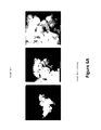
- FIGS. 5A and 5B are photos of lithiated conversion material deposited as thin film material processed according to embodiments of the present invention.
- FIGS. 6A and 6B are photos of lithiated conversion material in powder form processed according to embodiments of the present invention.
- FIG. 7 is a voltage versus capacity graph comparing the charged electrode film and lithiated electrode film processed according to embodiments of the present invention.
- FIGS. 8A and 8B are voltage versus capacity graphs comparing electrochemical performances of lithiated powders against conventional.
- the present invention is directed to energy storage devices and methods thereof. More specifically, embodiments of the present invention provide techniques for forming lithiated electrode material.
- a conversion material is processed using n-BuLi solution to form iron nanoparticles and lithiated fluoride and/or oxide material. There are other embodiments as well.
- any element in a claim that does not explicitly state “means for” performing a specified function, or “step for” performing a specific function, is not to be interpreted as a “means” or “step” clause as specified in 35 U.S.C. Section 112, Paragraph 6.
- the use of “step of” or “act of” in the Claims herein is not intended to invoke the provisions of 35 U.S.C. 112, Paragraph 6.
- conversion materials typically at the cathode portion of the battery
- conversion materials can provide many benefits and advantages, such as high energy density and low hysteresis.
- lithiation of conversion materials can be performed using solid state synthesis and solution process.
- the lithiation targets cover from FeF 3 , FeOF, and FeF 2 to other metal fluorides (e.g., CoF 2 , CuF 2 , NiF 2 , and others) in charged state, and the lithiation process produces products containing composite nanostructures.
- nanostructures include Fe 0 nanoparticles (and/or other metal nanoparticles) mixed with LiF nanoparticles forming regular nanodomains.
- the lithiated material produced in lithiation process can be used for making positive electrodes in conversion batteries without the need to fabricate Li metal as the anode.
- lithiation chemicals such as Li3N, and/or LiH can be used; in solution based processes, lithiation chemicals can be n-BuLi, n-hexyl lithium and/or LiBH4. It is to be appreciated that other materials are possible as well.
- the growth rate and the synthesis speed is control to obtain desirable nanoparticle size and distribution, as described below.
- the lithiation process can produce nanodomains containing metal and LiF nanoparticles, which can be cycled between 1.5-4.0 V (also potentially in larger voltage window). It is to be appreciated that a capacity of 200 mAh/g or higher can be reached for fully lithiated particles.
- FIG. 1 is a simplified flow diagram illustrating a process for processing lithiated conversion material according to embodiments of the present invention.
- This diagram is merely an example, which should not unduly limit the scope of the claims.
- One of ordinary skill in the art would recognize many variations, alternatives, and modifications. For example, various steps can be added, removed, repeated, overlapped, replaced, modified, and/or overlapped.
- n-BuLi material and iron fluoride material (FeF 3 ) material are mixed together. More specifically, the iron fluoride material is in a powder form, and the n-BuLi material is a solution.
- n-BuLi is an abbreviation referring to n-Butyllithium material with a molecular formula of C 4 H 9 Li, which is an organolithium reagent.
- the n-BuLi solution is characterized by a concentration of about 2M. It is to be appreciated that other concentration levels are possible as well, such as 0.5M, 1M, 10M, etc.
- the cathode conversion material is provided as a layer of thin-film, and the layer is characterized by a thickness of less than 100 um.
- the cathode conversion material comprises FeF 2 and/or FeF 3 material.
- the cathode conversion material may additionally include metal oxide material.
- the n-BuLi material is a solution and it is added to a container.
- the conversion material i.e., iron fluoride
- the conversion material is gradually (or performed in multiple steps) added to the n-BuLi so the two materials can be efficiently mixed.
- the temperature for the reaction is controlled.
- the n-BuLi temperature is predetermined to compensate for the heat generated by the reaction between the n-BuLi and the conversion material.
- the cathode conversion powder material is immersed within the n-BuLi solution for about 24 hours or even longer.
- a solid layer of a lithiated fluoride and/or oxide material and iron (Fe 0 ) nanoparticles and an organic byproduct material are formed over the surfaces of the cathode conversion material.
- centrifugation is performed to facilitate the reaction.
- the reaction mechanism between FeF 3 material and n-BuLi material can be attributed to alkyl group coupling and/or through ⁇ -hydride elimination.
- the mechanism for alkyl group coupling can be described by: 2FeF 3 +6 n BuLi ⁇ 2Fe—(LiF) 3 +3 n C 8 H 18 ( n Octane)
- the lithiated fluoride and/or oxide material is characterized by a primary size of about 10-300 nm containing a nanodomain of 1 to 5 nm homogeneously distributed Fe o and LiF nanoparticles, and a secondary size of about 200 nm up to microsize. It is to be appreciated that these particle sizes are suitable for manufacturing highly efficient secondary batteries, as explained below.
- the lithiated fluoride and/or oxide, and the iron nanoparticle can be readily used in the manufacturing of conversion batteries. For example, the
- Li 3 N with FeOF The mechanism for reaction between Li 3 N with FeOF can be described by: Li 3 N+FeOF ⁇ Fe 0 +LiFeO+2LiF+1 ⁇ 2N 2
- the organic byproduct e.g., octane, butane, and/or butene
- a substantially non-polar solvent such as hexane. It is to be appreciated that other types of solvents can be used as well.
- the layer of the lithiated fluoride and/or oxide material and the iron nanoparticles is then dried in a substantially vacuum environment at a temperature of between about 10 to 100 degrees Celsius to form a layer of lithiated cathode conversion material. In a specific embodiment, the drying temperature is about 80 degrees Celsius.
- the layer of lithiated cathode conversion material can be further processed. For example, carbon (C-65) additive and/or polymer binder (e.g., PVDF-HFP) can be added to the layer of lithiated cathode conversion material.
- the lithiated cathode conversion material is deposited on a cathode current collector, which can be aluminum, stainless steel, nickel, and/or other types of material.
- FIG. 2 is a simplified flow diagram illustrating a process of lithiating conversion material deposited on a current collector according to embodiments of the present invention. This diagram is merely an example, which should not unduly limit the scope of the claims. One of ordinary skill in the art would recognize many variations, alternatives, and modifications. For example, various steps can be added, removed, repeated, overlapped, replaced, modified, and/or overlapped.
- the process of lithiating conversion material is performed on the cathode conversion material, which is provided in step 201 , that is deposited on a current collector.
- the current collector can be made of aluminum, stainless steel, nickel, and/or other materials.
- the cathode conversion material is in a thin-film layer form and characterized by the thickness of less than 100 um. In a specific embodiment, the thickness is about 20 to 70 um.
- the conversion material comprises iron and fluoride and/or oxide material.
- an n-BuLi solution is needed to react with the cathode conversion material.
- an n-BuLi solution is provided and characterized by a concentration of about 2M. In a specific embodiment, the reaction concentration is about 0.5M to 1M. It is to be appreciated that the n-BuLi solution is substantially non-reactive with the current collector material.
- the surfaces of the cathode conversion material is immersed in the n-BuLi solution for at least 24 hours.
- the long immersion time is required to account for the slow reaction that takes time.
- Other durations may be possible as well, depending on the bathing condition of n-BuLi solution within the conversion material.
- the reaction time can be 1 hour, 2 hours and up to over 24 hours.
- the n-BuLi solution is stirred. It is to be appreciated that depending on the specific application, the immersion reaction is substantially exothermic and release heat, which is to be removed.
- the reaction takes place in a container or reaction vessel that is surrounding by cooling fluid, and the amount of cooling is controlled by a cooling apparatus, such as cooling bath.
- a cooling apparatus such as cooling bath.
- mixed chemicals such as acetone and/or dry ice, are used to lowered the temperature of the reactants.
- a substantially solid layer of a lithiated fluoride and/or oxide material and iron nanoparticles and an organic byproduct material are formed over the surfaces of the cathode conversion material.
- the lithiated fluoride and/or oxide material is characterized by a primary size of about 10-300 nm containing a nanodomain of 1 to 5 nm homogeneously distributed Fe o and LiF nanoparticles, and a secondary size of about 200 nm up to microsize.
- the organic byproduct is resulted from the reaction between the conversion material and the n-BuLi solution, where the n-BuLi solution contributes carbon material.
- the organic byproduct material is removed at step 205 using a substantially non-polar solvent.
- the solvent can be a hexane solution.
- the non-polar solvent is substantially non-reactive with the lithiated conversion material to prevent undesirable removal of conversion material.
- the surface of the layer of the lithiated fluoride and/or oxide material and the iron nanoparticles is dried at temperature of between about 10 to 100 degrees Celsius to form a layer of lithiated cathode conversion material.
- the drying is performed in a substantially vacuum environment.
- the drying temperature is about 80 degrees Celsius.
- the iron nanoparticles are characterized by a valence state of Fe 0 .
- the lithiated conversion material is further formulated.
- the layer of lithiated cathode conversion material is in a substantially formulated form with carbon additive and/or polymer binder by adding these materials.
- the carbon material can be carbon-65, Ketjen Black EC600JD (KJ600), and/or carbon material characterized by a high-surface-to-volume ratios
- the lithiated conversion material is used in the manufacturing of battery cell(s), at step 208 .
- electrolyte is deposited on the lithiated conversion material as the next step of processing.
- Other steps are to be performed as well, such as forming anode and anode current collector, etc.
- FIG. 3 is a simplified flow diagram illustrating a process of lithiating conversion material in powder form according to embodiments of the present invention. This diagram is merely an example, which should not unduly limit the scope of the claims.
- One of ordinary skill in the art would recognize many variations, alternatives, and modifications. For example, various steps can be added, removed, repeated, overlapped, replaced, modified, and/or overlapped.
- a powder material comprising iron material and fluoride material.
- the powder material may additionally include oxide material.
- the powder material is characterized by particle size of about 10 nm to 500 nm. Depending on the implementation, the powder material can have a size of about 50 nm to 70 nm. In an embodiment, the powder material can have a size of about 200 nm to 300 nm.
- a substantially non-polar solvent is prepared, and the powder material is immersed into the non-polar solvent to form a mixture material.
- the non-polar solvent facilitates reaction between the n-BuLi material and the conversion material.
- the non-polar solvent is characterized by a first molar quantity.
- n-BuLi solution is added to the mixture material.
- the n-BuLi solution is characterized by a second molar quantity.
- the ratio between the first quantity and the second quantity is at least about 1:3. Depending on the application, the ratio can be 1:3.1 to 1:3.5.
- the n-BuLi solution in an implementation, is added to the mixture material drop-wise, and if needed, while stirring the mixture material. For example, the mixture material is stirred by an automatic stir, while the n-BuLi is added to the mixture.
- a precipitated material is formed within the BuLi solution, at step 304 .
- the precipitated material comprises lithiated fluoride material, iron nanoparticles, and an organic byproduct.
- the lithiated fluoride and/or oxide material is characterized by a primary size of about 10-300 nm containing a nanodomain of 1 to 5 nm homogeneously distributed Fe o and LiF nanoparticles, and a secondary size of about 200 nm up to microsize.
- the organic byproduct is formed due to the organic material from the n-BuLi solution.
- the organic byproduct and excess n-BuLi material are removed from the precipitated material to obtain a lithiated conversion material.
- a non-polar solvent such as hexane, is used.
- the lithiated conversion is dried at temperature of between about 10 to 100 degrees Celsius.
- the drying is performed in a substantially vacuum environment.
- the drying temperature is about 80 degrees Celsius.
- the iron nanoparticles are characterized by a valence state of Fe 0 .
- the lithiated conversion material is further formulated.
- the layer of lithiated cathode conversion material is in a substantially formulated form with carbon additive and/or polymer binder by adding these materials.
- the lithiated conversion material can be deposited on a current collector, which can be made of aluminum, stainless steel, nickel, and/or other types of materials.
- the lithiated conversion material is used in the manufacturing of battery cell(s), at step 308 .
- electrolyte is deposited on the lithiated conversion material as the next step of processing.
- Other steps are to be performed as well, such as forming anode and anode current collector, etc.
- an electrochemical device utilizes the lithiated conversion material at its cathode component.
- an electrochemical device includes an anode current collector, a cathode current collector, and a layer of solid material positioned between the anode current collector and the cathode current collector, the solid material comprising iron nanoparticles and lithiated fluoride material characterized by a primary size of about 10-300 nm containing a nanodomain of 1 to 5 nm homogeneously distributed Fe o and LiF nanoparticles, and a secondary size of about 200 nm up to microsize.
- the solid material comprises substantially lithiated conversion material manufactured according to the processes described above.
- the layer of solid material may further include carbon material and/or polymer binder material. It is to be appreciated that the lithiated conversion material can provide a capacity of at least 200 mAh/g. There are other benefits as well.
- FIG. 4 is an XRD graph illustrating uniformity of conversion material manufactured using n-BuLi material according to an embodiment of the present invention.
- lithiated FeF 3 materials both annealed FeF 3 and solid state conversion material
- conversion material manufactured by other means exhibit much more non-uniformity demonstrated by the spikes in the XRD graph.
- uniformity is associated high performance and efficiency, and thus highly desirable.
- FIGS. 5A and 5B are photos of lithiated conversion material deposited as thin film material processed according to embodiments of the present invention.
- FIG. 5A shows a layer of lithiated conversion material on a 20 nm scale. As FIG. 5A shows, the particle sizes, which include both lithiated fluoride and iron nanoparticles, are substantially uniform. More specifically, the dark particles in FIG. 5A are iron nanoparticles.
- FIG. 5B shows the diffraction pattern of the lithiated conversion material. The concentric rings indicate that the material is substantially a crystalline structure with a high level of uniformity.
- FIGS. 6A and 6B are photos of lithiated conversion material in powder form processed according to embodiments of the present invention. As shown in FIG. 6A , the particle sizes for the lithiated conversion material is uniform, at 500 nm, 100 nm, and 50 nm scales. FIG. 6B shows the diffraction pattern of the lithiated conversion material in powder form. Similar to FIG. 5B , the concentric rings in FIG. 6 indicate that the material is substantially a crystalline structure with a high level of uniformity.
- FIG. 7 is a voltage versus capacity graph comparing the charged electrode film and lithiated electrode film processed according to embodiments of the present invention.
- the lithiated electrode film has close capacity and hysteresis performance to its charged counterparts, demonstrating the validity of chemical solution lithiation process, which can produce nanodomain (e.g., 1-5 nm) Fe and LiF nanoparticles well mixed together and exhibit excellent electrochemical performance.
- FIGS. 8A and 8B are voltage versus capacity graphs comparing electrochemical performances of lithiated powders against conventional.
- FIG. 8A shows the first cycling data in which the lithiated powder has a higher hysteresis in charging.
- FIG. 8B shows that from the second cycling and on, the high hysteresis of the lithiated powder is reduced, indicating the lithiated powders have also reached a high electrochemical performance.
- lithiated conversion material According to embodiments of the present invention, techniques for making lithiated conversion material according to embodiments of the present invention provide many benefits. As explained above, the lithiated material made according to embodiments of the present invention exhibit a high degree of uniformity at the nanometer scale, and thus afford a high level of performance and efficiency. The use of n-BuLi solution is compatible with existing techniques and available materials, and therefore can be used in large scale manufacturing process of electrochemical devices.
- processes according to the present invention provide better reaction control both, kinetically and hydrodynamically, in comparison to existing processes.
- the better reaction control affords better controlling of particle size and nanodomains for conversion batteries.
Abstract
Description
2FeF3+6nBuLi→2Fe—(LiF)3+3nC8H18(nOctane)
2FeF3+6nBuLi→2Fe—(LiF)3+3nC4H10(nbutane)+31-C4H8(1-butene)
Li3N+FeF3→Fe0+3LiF+½N2
Li3N+FeOF→Fe0+LiFeO+2LiF+½N2
Claims (15)
Priority Applications (1)
| Application Number | Priority Date | Filing Date | Title |
|---|---|---|---|
| US14/288,407 US9466830B1 (en) | 2013-07-25 | 2014-05-28 | Method and system for processing lithiated electrode material |
Applications Claiming Priority (2)
| Application Number | Priority Date | Filing Date | Title |
|---|---|---|---|
| US201361858602P | 2013-07-25 | 2013-07-25 | |
| US14/288,407 US9466830B1 (en) | 2013-07-25 | 2014-05-28 | Method and system for processing lithiated electrode material |
Publications (1)
| Publication Number | Publication Date |
|---|---|
| US9466830B1 true US9466830B1 (en) | 2016-10-11 |
Family
ID=57046645
Family Applications (1)
| Application Number | Title | Priority Date | Filing Date |
|---|---|---|---|
| US14/288,407 Expired - Fee Related US9466830B1 (en) | 2013-07-25 | 2014-05-28 | Method and system for processing lithiated electrode material |
Country Status (1)
| Country | Link |
|---|---|
| US (1) | US9466830B1 (en) |
Cited By (6)
| Publication number | Priority date | Publication date | Assignee | Title |
|---|---|---|---|---|
| WO2019172661A1 (en) * | 2018-03-07 | 2019-09-12 | 주식회사 엘지화학 | Method for manufacturing negative electrode |
| TWI754081B (en) * | 2017-07-07 | 2022-02-01 | 美商片片堅俄亥俄州工業公司 | Electrode binder slurry composition for lithium ion electrical storage devices |
| US11302967B2 (en) | 2018-01-15 | 2022-04-12 | International Business Machines Corporation | Low-voltage microbattery |
| US11424451B2 (en) | 2017-07-07 | 2022-08-23 | Ppg Industries Ohio, Inc. | Electrode slurry composition for lithium ion electrical storage devices |
| US11557756B2 (en) | 2014-02-25 | 2023-01-17 | Quantumscape Battery, Inc. | Hybrid electrodes with both intercalation and conversion materials |
| US11843118B2 (en) | 2017-07-07 | 2023-12-12 | Ppg Industries Ohio, Inc. | Electrode binder slurry composition for lithium ion electrical storage devices |
Citations (35)
| Publication number | Priority date | Publication date | Assignee | Title |
|---|---|---|---|---|
| US5296318A (en) | 1993-03-05 | 1994-03-22 | Bell Communications Research, Inc. | Rechargeable lithium intercalation battery with hybrid polymeric electrolyte |
| US5522955A (en) | 1994-07-07 | 1996-06-04 | Brodd; Ralph J. | Process and apparatus for producing thin lithium coatings on electrically conductive foil for use in solid state rechargeable electrochemical cells |
| US5788738A (en) | 1996-09-03 | 1998-08-04 | Nanomaterials Research Corporation | Method of producing nanoscale powders by quenching of vapors |
| US5824434A (en) | 1992-11-30 | 1998-10-20 | Canon Kabushiki Kaisha | Secondary battery |
| US6087042A (en) | 1996-10-18 | 2000-07-11 | Kabushiki Kaisha Toyota Chuo Kenkyusho | Positive electrode material for secondary lithium battery |
| US6635114B2 (en) | 1999-12-17 | 2003-10-21 | Applied Material, Inc. | High temperature filter for CVD apparatus |
| US6680145B2 (en) | 2001-08-07 | 2004-01-20 | 3M Innovative Properties Company | Lithium-ion batteries |
| US6689192B1 (en) | 2001-12-13 | 2004-02-10 | The Regents Of The University Of California | Method for producing metallic nanoparticles |
| US20040121235A1 (en) | 2002-10-01 | 2004-06-24 | Amatucci Glenn G. | Metal fluorides as electrode materials |
| US20040126659A1 (en) | 2002-09-10 | 2004-07-01 | Graetz Jason A. | High-capacity nanostructured silicon and lithium alloys thereof |
| US20040191633A1 (en) | 2003-02-26 | 2004-09-30 | The University Of Chicago | Electrodes for lithium batteries |
| US20060019163A1 (en) | 2002-10-01 | 2006-01-26 | Rutgers, The State University Of New Jersey | Copper fluoride based nanocomposites as electrode materials |
| US20070221635A1 (en) | 2006-03-08 | 2007-09-27 | Tekna Plasma Systems Inc. | Plasma synthesis of nanopowders |
| WO2008095197A2 (en) | 2007-02-02 | 2008-08-07 | Rutgers, The State University | Metal fluoride and phosphate nanocomposites as electrode materials |
| US7625671B2 (en) | 2002-10-01 | 2009-12-01 | Rutgers, The State University | Transition metal fluoride: carbon nanoamalgam rechargeable battery cell electrode material |
| EP1540752B1 (en) | 2002-09-13 | 2010-03-31 | Max-Planck-Gesellschaft zur Förderung der Wissenschaften e.V. | Novel electrodes for li-based electrochemical energy storage devices and a li-based electrochemical storage device |
| US20110065001A1 (en) | 2008-05-23 | 2011-03-17 | Nathalie Pereira | Iron Oxyfluoride Electrodes for Electrochemical Energy Storage |
| US7947392B2 (en) | 2004-10-01 | 2011-05-24 | Rutgers The State University of New Jersey, U.S. | Bismuth fluoride based nanocomposites as electrode materials |
| US8039149B2 (en) | 2004-10-01 | 2011-10-18 | Rutgers, The State University | Bismuth oxyfluoride based nanocomposites as electrode materials |
| US20120009469A1 (en) | 2003-10-14 | 2012-01-12 | Polyplus Battery Company | Active metal / aqueous electrochemical cells and systems |
| US20120032118A1 (en) | 2009-04-11 | 2012-02-09 | Maximilian Fichtner | Cathode material for fluoride-based conversion electrodes, method for the production thereof and use thereof |
| US20120225356A1 (en) | 2009-11-20 | 2012-09-06 | Ulrich Wietelmann | Galvanic elements containing oxygen-containing conversion electrodes |
| US20120263998A1 (en) | 2010-11-17 | 2012-10-18 | Uchicago Argonne, Llc | ELECTRODE STRUCTURES AND SURFACES FOR Li BATTERIES |
| US20130048924A1 (en) | 2009-11-09 | 2013-02-28 | Glenn G. Amatucci | Metal fluoride compositions for self formed batteries |
| US8388754B2 (en) | 2005-04-26 | 2013-03-05 | First Solar, Inc. | System and method for depositing a material on a substrate |
| US8449950B2 (en) | 2009-08-24 | 2013-05-28 | Applied Materials, Inc. | In-situ deposition of battery active lithium materials by plasma spraying |
| US8465602B2 (en) | 2006-12-15 | 2013-06-18 | Praxair S. T. Technology, Inc. | Amorphous-nanocrystalline-microcrystalline coatings and methods of production thereof |
| US20130344391A1 (en) | 2012-06-18 | 2013-12-26 | Sila Nanotechnologies Inc. | Multi-shell structures and fabrication methods for battery active materials with expansion properties |
| US20140170493A1 (en) | 2012-07-24 | 2014-06-19 | Quantumscape Corporation | Nanostructured materials for electrochemical conversion reactions |
| US20140272564A1 (en) | 2013-03-13 | 2014-09-18 | Quantumscape Corporation | Iron, fluorine, sulfur compounds for battery cell cathodes |
| US20140284526A1 (en) | 2013-03-21 | 2014-09-25 | Quantumscape Corporation | Method for forming metal fluoride material |
| WO2014186634A2 (en) | 2013-05-15 | 2014-11-20 | Quantumscape Corporation | Solid state catholyte or electrolyte for battery using liampbsc (m = si, ge, and/or sn) |
| WO2014197751A1 (en) | 2013-06-06 | 2014-12-11 | Quantumscape Corporation | Flash evaporation of solid state battery component |
| WO2015054320A2 (en) | 2013-10-07 | 2015-04-16 | Quantumscape Corporation | Garnet materials for li secondary batteries and methods of making and using garnet materials |
| US9048497B2 (en) | 2012-10-05 | 2015-06-02 | Rutgers, The State University Of New Jersey | Metal fluoride compositions for self formed batteries |
-
2014
- 2014-05-28 US US14/288,407 patent/US9466830B1/en not_active Expired - Fee Related
Patent Citations (40)
| Publication number | Priority date | Publication date | Assignee | Title |
|---|---|---|---|---|
| US5824434A (en) | 1992-11-30 | 1998-10-20 | Canon Kabushiki Kaisha | Secondary battery |
| US5296318A (en) | 1993-03-05 | 1994-03-22 | Bell Communications Research, Inc. | Rechargeable lithium intercalation battery with hybrid polymeric electrolyte |
| US5522955A (en) | 1994-07-07 | 1996-06-04 | Brodd; Ralph J. | Process and apparatus for producing thin lithium coatings on electrically conductive foil for use in solid state rechargeable electrochemical cells |
| US5788738A (en) | 1996-09-03 | 1998-08-04 | Nanomaterials Research Corporation | Method of producing nanoscale powders by quenching of vapors |
| US6087042A (en) | 1996-10-18 | 2000-07-11 | Kabushiki Kaisha Toyota Chuo Kenkyusho | Positive electrode material for secondary lithium battery |
| US6635114B2 (en) | 1999-12-17 | 2003-10-21 | Applied Material, Inc. | High temperature filter for CVD apparatus |
| US6680145B2 (en) | 2001-08-07 | 2004-01-20 | 3M Innovative Properties Company | Lithium-ion batteries |
| US6689192B1 (en) | 2001-12-13 | 2004-02-10 | The Regents Of The University Of California | Method for producing metallic nanoparticles |
| US20040126659A1 (en) | 2002-09-10 | 2004-07-01 | Graetz Jason A. | High-capacity nanostructured silicon and lithium alloys thereof |
| EP1540752B1 (en) | 2002-09-13 | 2010-03-31 | Max-Planck-Gesellschaft zur Förderung der Wissenschaften e.V. | Novel electrodes for li-based electrochemical energy storage devices and a li-based electrochemical storage device |
| US20040121235A1 (en) | 2002-10-01 | 2004-06-24 | Amatucci Glenn G. | Metal fluorides as electrode materials |
| US20060019163A1 (en) | 2002-10-01 | 2006-01-26 | Rutgers, The State University Of New Jersey | Copper fluoride based nanocomposites as electrode materials |
| US7371338B2 (en) | 2002-10-01 | 2008-05-13 | Rutgers, The State University | Metal fluorides as electrode materials |
| US7625671B2 (en) | 2002-10-01 | 2009-12-01 | Rutgers, The State University | Transition metal fluoride: carbon nanoamalgam rechargeable battery cell electrode material |
| US20040191633A1 (en) | 2003-02-26 | 2004-09-30 | The University Of Chicago | Electrodes for lithium batteries |
| US20120009469A1 (en) | 2003-10-14 | 2012-01-12 | Polyplus Battery Company | Active metal / aqueous electrochemical cells and systems |
| US8039149B2 (en) | 2004-10-01 | 2011-10-18 | Rutgers, The State University | Bismuth oxyfluoride based nanocomposites as electrode materials |
| US7947392B2 (en) | 2004-10-01 | 2011-05-24 | Rutgers The State University of New Jersey, U.S. | Bismuth fluoride based nanocomposites as electrode materials |
| US8388754B2 (en) | 2005-04-26 | 2013-03-05 | First Solar, Inc. | System and method for depositing a material on a substrate |
| US20070221635A1 (en) | 2006-03-08 | 2007-09-27 | Tekna Plasma Systems Inc. | Plasma synthesis of nanopowders |
| US8465602B2 (en) | 2006-12-15 | 2013-06-18 | Praxair S. T. Technology, Inc. | Amorphous-nanocrystalline-microcrystalline coatings and methods of production thereof |
| WO2008095197A2 (en) | 2007-02-02 | 2008-08-07 | Rutgers, The State University | Metal fluoride and phosphate nanocomposites as electrode materials |
| US20080199772A1 (en) | 2007-02-02 | 2008-08-21 | Glenn Amatucci | Metal Fluoride And Phosphate Nanocomposites As Electrode Materials |
| US8518604B2 (en) | 2007-02-02 | 2013-08-27 | Rutgers, The State University Of New Jersey | Metal fluoride and phosphate nanocomposites as electrode materials |
| US20110065001A1 (en) | 2008-05-23 | 2011-03-17 | Nathalie Pereira | Iron Oxyfluoride Electrodes for Electrochemical Energy Storage |
| US8623549B2 (en) | 2008-05-23 | 2014-01-07 | Nathalie Pereira | Iron oxyfluoride electrodes for electrochemical energy storage |
| US20120032118A1 (en) | 2009-04-11 | 2012-02-09 | Maximilian Fichtner | Cathode material for fluoride-based conversion electrodes, method for the production thereof and use thereof |
| US8449950B2 (en) | 2009-08-24 | 2013-05-28 | Applied Materials, Inc. | In-situ deposition of battery active lithium materials by plasma spraying |
| US20130048924A1 (en) | 2009-11-09 | 2013-02-28 | Glenn G. Amatucci | Metal fluoride compositions for self formed batteries |
| US20120225356A1 (en) | 2009-11-20 | 2012-09-06 | Ulrich Wietelmann | Galvanic elements containing oxygen-containing conversion electrodes |
| US20120263998A1 (en) | 2010-11-17 | 2012-10-18 | Uchicago Argonne, Llc | ELECTRODE STRUCTURES AND SURFACES FOR Li BATTERIES |
| US20130344391A1 (en) | 2012-06-18 | 2013-12-26 | Sila Nanotechnologies Inc. | Multi-shell structures and fabrication methods for battery active materials with expansion properties |
| WO2013192205A1 (en) | 2012-06-18 | 2013-12-27 | Sila Nanotechnologies Inc. | Multi-shell structures for battery active materials with expansion properties |
| US20140170493A1 (en) | 2012-07-24 | 2014-06-19 | Quantumscape Corporation | Nanostructured materials for electrochemical conversion reactions |
| US9048497B2 (en) | 2012-10-05 | 2015-06-02 | Rutgers, The State University Of New Jersey | Metal fluoride compositions for self formed batteries |
| US20140272564A1 (en) | 2013-03-13 | 2014-09-18 | Quantumscape Corporation | Iron, fluorine, sulfur compounds for battery cell cathodes |
| US20140284526A1 (en) | 2013-03-21 | 2014-09-25 | Quantumscape Corporation | Method for forming metal fluoride material |
| WO2014186634A2 (en) | 2013-05-15 | 2014-11-20 | Quantumscape Corporation | Solid state catholyte or electrolyte for battery using liampbsc (m = si, ge, and/or sn) |
| WO2014197751A1 (en) | 2013-06-06 | 2014-12-11 | Quantumscape Corporation | Flash evaporation of solid state battery component |
| WO2015054320A2 (en) | 2013-10-07 | 2015-04-16 | Quantumscape Corporation | Garnet materials for li secondary batteries and methods of making and using garnet materials |
Non-Patent Citations (71)
Cited By (9)
| Publication number | Priority date | Publication date | Assignee | Title |
|---|---|---|---|---|
| US11557756B2 (en) | 2014-02-25 | 2023-01-17 | Quantumscape Battery, Inc. | Hybrid electrodes with both intercalation and conversion materials |
| TWI754081B (en) * | 2017-07-07 | 2022-02-01 | 美商片片堅俄亥俄州工業公司 | Electrode binder slurry composition for lithium ion electrical storage devices |
| US11424451B2 (en) | 2017-07-07 | 2022-08-23 | Ppg Industries Ohio, Inc. | Electrode slurry composition for lithium ion electrical storage devices |
| US11764361B2 (en) | 2017-07-07 | 2023-09-19 | Ppg Industries Ohio, Inc. | Electrode slurry composition for lithium ion electrical storage devices |
| US11799086B2 (en) | 2017-07-07 | 2023-10-24 | Ppg Industries Ohio, Inc. | Electrode binder slurry composition for lithium ion electrical storage devices |
| US11843118B2 (en) | 2017-07-07 | 2023-12-12 | Ppg Industries Ohio, Inc. | Electrode binder slurry composition for lithium ion electrical storage devices |
| US11302967B2 (en) | 2018-01-15 | 2022-04-12 | International Business Machines Corporation | Low-voltage microbattery |
| WO2019172661A1 (en) * | 2018-03-07 | 2019-09-12 | 주식회사 엘지화학 | Method for manufacturing negative electrode |
| US11211595B2 (en) | 2018-03-07 | 2021-12-28 | Lg Chem, Ltd. | Method for manufacturing negative electrode |
Similar Documents
| Publication | Publication Date | Title |
|---|---|---|
| US9466830B1 (en) | Method and system for processing lithiated electrode material | |
| Kubota et al. | Towards K‐ion and Na‐ion batteries as “beyond Li‐ion” | |
| Srour et al. | Ionic liquid-based electrolytes for lithium-ion batteries: review of performances of various electrode systems | |
| Kang et al. | Enhancing the rate capability of high capacity xLi2MnO3·(1− x) LiMO2 (M= Mn, Ni, Co) electrodes by Li–Ni–PO4 treatment | |
| Ding et al. | Recent advances in cathode prelithiation additives and their use in lithium–ion batteries | |
| Omarova et al. | Nickel hexacyanoferrate nanoparticles as a low cost cathode material for lithium-ion batteries | |
| CN106410157B (en) | High-magnification long-life cathode material and preparation method thereof | |
| Qin et al. | A ternary molten salt approach for direct regeneration of LiNi0. 5Co0. 2Mn0. 3O2 cathode | |
| Hu et al. | High-conductive AZO nanoparticles decorated Ni-rich cathode material with enhanced electrochemical performance | |
| Jiang et al. | Synthesis of Ni-rich layered-oxide nanomaterials with enhanced Li-ion diffusion pathways as high-rate cathodes for Li-ion batteries | |
| Zhong et al. | The polyacrylic latex: an efficient water-soluble binder for LiNi 1/3 Co 1/3 Mn 1/3 O 2 cathode in li-ion batteries | |
| CN106571466B (en) | All-solid-state battery | |
| Lin et al. | Porous Li4Ti5O12 anode material synthesized by one-step solid state method for electrochemical properties enhancement | |
| KR101684082B1 (en) | Lithium cathode active materials, anode active materials coated with polymer and lithiumsecondary battery using the same, and preparation method thereof | |
| CN105814719A (en) | Positive electrode active material for lithium secondary battery, and lithium secondary battery comprising same | |
| CN102683665B (en) | Lithium-vanadium oxide over-long nano wire and preparation method and application thereof | |
| CN103403932A (en) | Electrode active substance and method for producing same | |
| WO2014092330A1 (en) | Electrode for lithium secondary battery, lithium secondary battery using same and method for manufacturing same | |
| Huang et al. | Nanoscale LiNi0. 5Co0. 2Mn0. 3O2 cathode materials for lithium ion batteries via a polymer-assisted chemical solution method | |
| CN109417165A (en) | Including core and the positive electrode active materials particle of shell of phosphoric acid cobalt lithium and preparation method thereof containing lithium and cobalt oxides | |
| CN113169333A (en) | Positive electrode active material for lithium secondary battery and lithium secondary battery comprising same | |
| Li et al. | ZnO-coated LiMn 2 O 4 cathode material for lithium-ion batteries synthesized by a combustion method | |
| CN103915623B (en) | The preparation method of nano porous metal sulfide rechargeable magnesium cell anode material | |
| Zhong et al. | Study on x LiVPO4F· y Li3V2 (PO4) 3/C Composite for High-Performance Cathode Material for Lithium-Ion Batteries | |
| Zhao et al. | Advanced structures in electrodeposited tin base anodes for lithium ion batteries |
Legal Events
| Date | Code | Title | Description |
|---|---|---|---|
| AS | Assignment |
Owner name: QUANTUMSCAPE CORPORATION, CALIFORNIA Free format text: ASSIGNMENT OF ASSIGNORS INTEREST;ASSIGNORS:SHAN, JINGNING;ZHANG, WEI;FASCHING, RAINER;AND OTHERS;SIGNING DATES FROM 20151023 TO 20151102;REEL/FRAME:036983/0503 |
|
| STCF | Information on status: patent grant |
Free format text: PATENTED CASE |
|
| FEPP | Fee payment procedure |
Free format text: ENTITY STATUS SET TO UNDISCOUNTED (ORIGINAL EVENT CODE: BIG.); ENTITY STATUS OF PATENT OWNER: LARGE ENTITY |
|
| FEPP | Fee payment procedure |
Free format text: MAINTENANCE FEE REMINDER MAILED (ORIGINAL EVENT CODE: REM.); ENTITY STATUS OF PATENT OWNER: LARGE ENTITY |
|
| LAPS | Lapse for failure to pay maintenance fees |
Free format text: PATENT EXPIRED FOR FAILURE TO PAY MAINTENANCE FEES (ORIGINAL EVENT CODE: EXP.); ENTITY STATUS OF PATENT OWNER: LARGE ENTITY |
|
| STCH | Information on status: patent discontinuation |
Free format text: PATENT EXPIRED DUE TO NONPAYMENT OF MAINTENANCE FEES UNDER 37 CFR 1.362 |
|
| FP | Lapsed due to failure to pay maintenance fee |
Effective date: 20201011 |