US9469410B2 - Aerial refueling system, apparatus and methods - Google Patents
Aerial refueling system, apparatus and methods Download PDFInfo
- Publication number
- US9469410B2 US9469410B2 US13/188,716 US201113188716A US9469410B2 US 9469410 B2 US9469410 B2 US 9469410B2 US 201113188716 A US201113188716 A US 201113188716A US 9469410 B2 US9469410 B2 US 9469410B2
- Authority
- US
- United States
- Prior art keywords
- drogue
- probe
- aircraft
- hose
- signal
- Prior art date
- Legal status (The legal status is an assumption and is not a legal conclusion. Google has not performed a legal analysis and makes no representation as to the accuracy of the status listed.)
- Active, expires
Links
- 238000000034 method Methods 0.000 title description 9
- 239000000523 sample Substances 0.000 claims abstract description 102
- 238000010168 coupling process Methods 0.000 claims abstract description 41
- 230000008878 coupling Effects 0.000 claims abstract description 40
- 238000005859 coupling reaction Methods 0.000 claims abstract description 40
- 239000000446 fuel Substances 0.000 claims description 14
- 230000001960 triggered effect Effects 0.000 claims description 8
- 230000033001 locomotion Effects 0.000 claims description 7
- 230000008859 change Effects 0.000 claims description 4
- 230000011664 signaling Effects 0.000 claims description 2
- 230000000977 initiatory effect Effects 0.000 claims 1
- 230000004044 response Effects 0.000 description 12
- 239000002828 fuel tank Substances 0.000 description 8
- 238000006073 displacement reaction Methods 0.000 description 4
- 230000003287 optical effect Effects 0.000 description 4
- 238000006243 chemical reaction Methods 0.000 description 3
- 230000008569 process Effects 0.000 description 3
- 238000004891 communication Methods 0.000 description 2
- 239000012530 fluid Substances 0.000 description 2
- 239000004020 conductor Substances 0.000 description 1
- 230000003111 delayed effect Effects 0.000 description 1
- 230000000694 effects Effects 0.000 description 1
- 230000010006 flight Effects 0.000 description 1
- 230000007257 malfunction Effects 0.000 description 1
- 238000005259 measurement Methods 0.000 description 1
- 230000007246 mechanism Effects 0.000 description 1
- 230000010355 oscillation Effects 0.000 description 1
- 238000000926 separation method Methods 0.000 description 1
- 230000001052 transient effect Effects 0.000 description 1
Images


Classifications
-
- B—PERFORMING OPERATIONS; TRANSPORTING
- B64—AIRCRAFT; AVIATION; COSMONAUTICS
- B64D—EQUIPMENT FOR FITTING IN OR TO AIRCRAFT; FLIGHT SUITS; PARACHUTES; ARRANGEMENTS OR MOUNTING OF POWER PLANTS OR PROPULSION TRANSMISSIONS IN AIRCRAFT
- B64D45/00—Aircraft indicators or protectors not otherwise provided for
-
- B—PERFORMING OPERATIONS; TRANSPORTING
- B64—AIRCRAFT; AVIATION; COSMONAUTICS
- B64D—EQUIPMENT FOR FITTING IN OR TO AIRCRAFT; FLIGHT SUITS; PARACHUTES; ARRANGEMENTS OR MOUNTING OF POWER PLANTS OR PROPULSION TRANSMISSIONS IN AIRCRAFT
- B64D39/00—Refuelling during flight
- B64D39/02—Means for paying-in or out hose
-
- B—PERFORMING OPERATIONS; TRANSPORTING
- B64—AIRCRAFT; AVIATION; COSMONAUTICS
- B64D—EQUIPMENT FOR FITTING IN OR TO AIRCRAFT; FLIGHT SUITS; PARACHUTES; ARRANGEMENTS OR MOUNTING OF POWER PLANTS OR PROPULSION TRANSMISSIONS IN AIRCRAFT
- B64D39/00—Refuelling during flight
- B64D39/06—Connecting hose to aircraft; Disconnecting hose therefrom
-
- B—PERFORMING OPERATIONS; TRANSPORTING
- B64—AIRCRAFT; AVIATION; COSMONAUTICS
- B64D—EQUIPMENT FOR FITTING IN OR TO AIRCRAFT; FLIGHT SUITS; PARACHUTES; ARRANGEMENTS OR MOUNTING OF POWER PLANTS OR PROPULSION TRANSMISSIONS IN AIRCRAFT
- B64D47/00—Equipment not otherwise provided for
- B64D47/02—Arrangements or adaptations of signal or lighting devices
-
- B—PERFORMING OPERATIONS; TRANSPORTING
- B64—AIRCRAFT; AVIATION; COSMONAUTICS
- B64D—EQUIPMENT FOR FITTING IN OR TO AIRCRAFT; FLIGHT SUITS; PARACHUTES; ARRANGEMENTS OR MOUNTING OF POWER PLANTS OR PROPULSION TRANSMISSIONS IN AIRCRAFT
- B64D2203/00—Aircraft or airfield lights using LEDs
Definitions
- the present invention relates to aerial refueling, and more particularly relates to improved system, apparatus and methods for controlling the slack in the refueling hose during the refueling operation.
- the process of aerial refueling is well known and allows a plane or other aircraft to be refueled in flight without the need to land. This is typically used by the military for long distance flights where landing of the air craft would be impossible, unsafe or otherwise undesirable.
- the refueling process consists of a leading aircraft which refuels a trailing aircraft via a rigid boom or flexible hose that typically includes a funnel-shaped device (referred to as a “drogue”) at the free end thereof which releasably engages with a probe leading to the fuel tank of the trailing aircraft.
- the trailing aircraft probe With the leading aircraft travelling at a constant speed and the hose/drogue freely extending therebehind, the trailing aircraft probe is aligned with the drogue and its speed is increased in an attempt to couple the probe and drogue. This maneuver is typically called “making a run at the drogue”. Sometimes the alignment is off and the coupling fails whereupon the sequence is repeated until a successful coupling has occurred.
- fuel may be delivered from an auxiliary fuel tank on the leading aircraft through the boom or hose to the probe of the trailing aircraft which leads to the trailing aircraft fuel tank(s), thereby refueling the trailing aircraft during flight.
- the '212 patent utilizes a reaction torque sensor and microprocessor which connects to the control valve of a variable displacement hydraulic motor which controls the deployment and retraction of the hose reel.
- the microprocessor receives data relating to the reaction torque on the hose reel (i.e., as a result of contact of the receiving aircraft's refueling probe with the drogue and/or air stream effects) from the reaction torque sensor 36 which is preferably a load cell electrically connected to the microprocessor.
- the microprocessor also receives data on the position (speed and direction) of the hose from a tachometer/position sensor 34 which is preferably connected to the drive shaft of the hose reel to measure how much length and how fast the hose is deploying from the reel.
- the microprocessor then sends signals to the hydraulic motor control valve in response to the signals it receives from the command instructions initiated by the tanker aircraft's pilot or by avionic equipment (e.g., deploy or retract hose), as well as the tachometer/position sensor and torque sensor.
- the hose is controlled in this instance by sensing the position and speed of the hose as it leaves the reel, and the torque on the reel as caused by forces acting on the drogue by the probe and/or air currents.
- the free drag torque is compared to the net drag torque and signals are generated and sent to the control valve according to the microprocessor algorithm.
- the '228 patent which is a continuation-in-part of the '212 patent, discloses the further step of retracting the hose prior to hook-up with the probe to record the free hose retraction force which is then compared to the retraction force following engagement with retraction continuing until the retraction force rises to about the same force as previously recorded.
- the '455 patent discloses drogue and probe positors (position sensors, transmitters and/or receivers) which are capable of determining the relative positions of the drogue and probe. Once the probe and drogue are in orthogonal alignment, the hose is extended further to reach and engage the probe (this is opposed to the trailing aircraft making a run at the drogue which the inventor states can cause slack in the hose). Air jets (thrusters) about the drogue may also be used to assist in the alignment of the probe and drogue.
- the present invention addresses the above need by providing, in one embodiment of the invention, an in-flight refueling system between a leading aircraft and a trailing aircraft through a hose having a first end attached to said leading aircraft and a second, free end connected to a drogue, the trailing aircraft having a probe in fluid communication with the trailing aircraft fuel tank, the probe adapted to releasably couple with said drogue while the leading and trailing aircraft are both in flight, said system comprising:
- the actuator may be an electric motor or hydraulic motor, for example, connected to the hose reel.
- the signal emitted by the drogue/probe coupling event may be designed as a predetermined function that varies according to the desired motor response or as a discrete on-off function.
- the trigger device may be anything that is capable of responding to a drogue/probe coupling event which occurs when the probe has fully coupled with the drogue which, in turn, initiates fuel delivery through the hose to the probe and fuel tank of the trailing aircraft.
- the trigger device is a mechanical switch that is located within the funnel of the drogue in a normally open position.
- one or more biased rollers are present in the drogue over which the outer surface of the probe passes as it enters the drogue. As the probe passes over the rollers, the rollers deflect a small amount in a radially outward direction.
- the switch may be attached to one or more of these rollers such that the switch closes when the respective roller deflects under pressure from the probe.
- the trigger device is a sensor which is activated by the probe when the probe has coupled with the drogue.
- the sensor may be a light source (e.g., LED) and a light detector positioned opposite each other in the drogue funnel beyond the location of the rollers in a direction toward the hose. With the light source normally on, the detector is receiving the signal from the light source. When the light path is broken by the probe passing therethrough (indicating a coupling event), the detector responds by sending a signal to the actuator on the leading aircraft hose reel which, in turn, responds by taking up slack in the hose.
- a light source e.g., LED
- the detector With the light source normally on, the detector is receiving the signal from the light source.
- the detector responds by sending a signal to the actuator on the leading aircraft hose reel which, in turn, responds by taking up slack in the hose.
- trigger device may be any type of proximity sensor that is positioned to activate upon sensing the probe has entered the drogue a distance sufficient to indicate a coupling event.
- the trigger devices described herein may work in the reverse to signal a decoupling event which occurs when the probe detaches from the drogue. This may be intentional, as when the fueling operation is completed, or unintentional due to such things as mechanical failure, unintentional pull away of the leading and trailing aircraft, and excessive wind forces, for example. Appropriate system responses (e.g., reel rewind of the hose) may then be designed into the system.
- FIG. 1 is a simplified side elevational view of a leading aircraft refueling a trailing aircraft
- FIG. 2 is a side elevational view of an embodiment of the probe of the present invention.
- FIG. 3A is a simplified schematic representation of an embodiment of the present invention.
- FIG. 3B is a simplified schematic representation of another embodiment of the present invention.
- FIG. 3C is a simplified schematic representation of yet another embodiment of the present invention.
- FIG. 3D is a simplified schematic representation of still another embodiment of the present invention.
- FIG. 4A is a simplified schematic representation of an embodiment of the invention showing the refueling pod with hose and drogue;
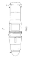
- FIG. 4B is a rear elevational view of an embodiment of the drogue
- FIG. 5A is a fragmented side elevational view of the drogue and probe immediately prior to engagement with one another;
- FIG. 5B is a fragmented side elevational view of the drogue and probe in full engagement with one another;
- FIG. 5C is a cross-sectional view of the drogue as taken generally along the line 5 C- 5 C in FIG. 5A ;
- FIG. 6 is a view similar to FIG. 5B showing another embodiment of the invention.
- FIGS. 7A-C are schematic representations of drogue-probe coupling event and concomitant signal and hose reel actuator responses.
- FIGS. 8A-B are schematic representations of drogue-probe uncoupling event and concomitant signal and hose reel actuator responses.
- FIG. 1 a simplified elevational view of a first plane, or leading aircraft 10 , and a second plane, or trailing aircraft 12 , which is to receive fuel from the leading aircraft 10 .
- the leading aircraft 10 includes a fuel tank which may be in the form of an auxiliary fuel pod 14 (see also FIG. 4A ).
- a fuel hose 16 connects to the fuel pod 14 and is carried on a hose reel 18 (depicted schematically in FIGS. 3A-D ) which rotates in either direction to alternately retract and wind the hose on the reel, or unwind and feed the hose from the reel.
- a hydraulic motor such as a hydraulic hose reel motor 20 as seen in FIGS. 3A-C , or an electric motor 22 as seen in FIG. 3D may be used as the hose reel actuator as will be explained more fully below.
- Hose 16 includes a free end 16 ′ located opposite the end which connects to the hose reel 18 .
- a drogue 26 is attached to hose free end 16 ′ and is funnel-shaped to provide a wide opening for the probe 28 of the trailing aircraft 12 .
- probe 28 connects to a hose fuel line that is in fluid communication with the fuel tank (not shown) of the trailing aircraft 12 .
- Probe 28 is configured to releasably couple with drogue 26 .
- drogue 26 includes a narrowed neck portion 26 b which includes one or more roller elements 30 , and preferably three roller elements 30 a - c positioned in substantially equally annularly spaced relation about neck portion 26 b (see FIG. 5C ).
- Probe 28 is elongated having a free distal end 28 a and opposite proximal end 28 b which attaches to the hose leading to the trailing aircraft fuel tank. Probe 28 further includes a narrowed ring segment 28 c which is configured to engage with rollers 30 a - c .
- FIG. 5A shows probe 28 entering drogue opening 26 a and FIGS. 5B and 6 show full coupling of the probe 28 to the drogue 26 with the drogue rollers (only roller 30 a seen) located within narrowed ring segment 28 c.
- the roller elements 30 a - c are each carried on another element which causes the rollers to be biased radially inwardly through a respective opening 27 a - c in neck segment 26 b toward the longitudinal axis X-X of drogue 26 ( FIG. 5C ).
- one or more rollers 30 a - c are carried on a respective pivoting connecting arm 32 a - c (only roller 30 a and arm 31 a shown).
- the rollers 30 a - c are normally biased radially inwardly (e.g., by a piston and connecting rod assembly 39 seen in FIG. 6 ) and deflect radially outwardly against the bias by the force of the probe outer surface segment 28 d which is located distally of ring segment 28 c (toward probe end 28 a ).
- probe outer surface segment 28 d tapers outwardly in the proximal direction to a maximum diameter D 1 ( FIG. 5B ) that is greater than the diameter D 2 of the imaginary circle “C” defined by the normally inwardly biased roller elements 30 a - c ( FIG. 5C ).
- Uncoupling of the drogue and probe is accomplished by a retraction force of probe 28 in the opposite direction away from drogue 26 .
- the retraction force must of course be strong enough to overcome the bias of the roller elements 30 a - c and this bias is therefore calculated and set to avoid unintentional decoupling due to the usual transient forces (e.g., cross winds) that may occur during the refueling process as is well known to those skilled in the art.
- the present invention utilizes the full drogue-probe coupling event as a control parameter in the hose control methodology of the aerial refueling system. Since coupling is achieved upon rollers 30 a - c locating within narrowed ring segment 28 c as described above, one or more trigger devices may be positioned at or adjacent the roller/ring segment interface such that the trigger devices are trigged once the rollers 30 a - c have located within the ring segment 28 c.
- the one or more trigger devices may be in the form of a sensor that is “tripped” by the presence of the probe 28 in the fully coupled position with drogue 26 .
- the word “tripped” is meant to indicate any detectable change in condition including, for example, an “on” to “off” condition or vice versa.
- a proximity sensor such as a light source (e.g., LED) 40 and a light detector 42 may be positioned opposite each other within drogue 26 distally of roller elements 30 a - c .
- FIG. 5A depicts an uninterrupted light beam between source 40 and detector 42 which is indicative of a “not coupled” condition between drogue 26 and probe 28 .
- FIG. 5B illustrates a full coupling event between drogue 26 and probe 28 wherein light line L 1 is no longer present, having been interrupted by the presence of probe 28 .
- Detector 42 which is no longer receiving a light signal from light source 40 , emits a signal which is received by one or more signal receiving devices on the leading aircraft 10 .
- the signal emitting devices may be modulated at a predetermined frequency.
- the signal emitting devices may be one of LEDs, infrared diodes, lasers, or radio or microwave emitters. Of course, it should be noted that the signal emitting devices may be any other type of devices capable of emitting signals that are known in the art.
- the signals emitted by the signal emitting devices may be received by signal receiving devices positioned on the leading aircraft 10 .
- the signal receiving device controls the actuator which, in turn, controls the hose reel which thereby takes up slack in the hose upon the drogue/probe coupling event, as more fully explained below.
- the signal emitting devices in some embodiments, may be modulated at a predetermined frequency.
- light source 40 and light detector 42 may be positioned a distance from roller elements 30 a - c which is about the same as or slightly shorter than the distance from probe tip 28 a to ring segment 28 c . As such, the light beam L 1 will not be interrupted until the probe has fully coupled with the drogue.
- the senor may be connected to a timer which prevents a signal being sent until a predetermined time period has passed (e.g., 50 milliseconds). This would prevent a coupling event signal being sent when the probe enters but fails to completely couple with the drogue and withdraws quickly due to unexpected turbulence, for example.
- a predetermined time period e.g. 50 milliseconds
- the one or more trigger devices may be directly connected to a respective roller element 30 a - c such that the trigger device is triggered in response to the movement of the roller element connecting arm which occurs when the probe enters the drogue, as described above.
- roller elements 30 a - c are each attached (only 30 a shown) to the free end 32 a ′ of a respective arm 32 a , the opposite end of which is pivotally connected at pivot point 32 a ′′ to the drogue 26 .
- One or more switches 44 , 46 may be positioned such that they are closed upon entry of the probe 28 into drogue 26 .
- any type of suitable switch may be used, for example, a contact switch 44 positioned to be tripped by a coupled probe 28 , or a mechanical switch 46 which is closed by movement of connecting arm 32 a caused by a coupled probe 28 .
- the optimal positions of the switches will be determined according to design preference but are desirably positioned so as to not be accidentally tripped by a “no couple” event.
- a variety of different types of signal sending and signal receiving devices may be used to indicate a coupling event between the drogue and probe.
- all types of signal sending devices in the Figures are represented generally by the reference numeral 100 and all types of signal receiving devices are represented generally by the reference numeral 200 .
- specific embodiments of the signal sending and receiving devices are also represented by unique reference numerals as set forth below.
- the signal sending means may be in the form of optical elements (e.g. including but not limited to lasers, LEDs (light emitting diodes), strobe lights, etc.) that may be perceived by a receiving device when the one or more optical elements are activated by a coupling event trigger.
- optical elements e.g. including but not limited to lasers, LEDs (light emitting diodes), strobe lights, etc.
- one or more LEDs 52 may be positioned in any desired strategic location such as the drogue rearward facing surface 26 b .
- the signal receiving element may be in the form of an optical sensor 54 located in a desired strategic signal-pick-up location such as the aircraft or fuel pod 14 , for example ( FIG. 4A ). More than one optical sensor may be provided as indicated at 56 to provide redundancy should the main sensor 54 malfunction or fail to see the coupling signal due to lack of line-of-sight and/or physical or atmospheric interference between the signal sending device and the main signal receiving device.
- the signal sending device may be in the form of a radio signal 58 which may be received by a radio detector or receiver 60 as seen in FIG. 3C .
- the radio receiver 60 is connected to the hose reel motor controller 23 which is connected to the hose reel motor 22 and hose reel 18 .
- the radio receiver 60 may be programmed to a predetermined frequency (see pulse 62 in FIG. 3C ) which may be used to ensure the coupling event has taken place. For example, a failed coupling event may trigger a very short pulse which is considered a false positive signal. In this instance, the radio receiver or other signal receiver would not cause the hose reel controller 23 to activate to take up hose slack.
- the receiver will only activate the hose reel controller when the parameter or predetermined threshold is reached which is indicative of a successful coupling event.
- any signal sending device may be matched to any cooperative signal receiving device and it is therefore understood the invention is not limited to the specific signal sending/receiver combinations illustrated in the Figures.
- the hose reel controller may also be of any desired type (e.g., hydraulic or electric controlled) and the invention is not limited to the specific embodiments shown and described herein.
- the signal sending device 100 is connected to a conductor (wire) 68 which is connected to and travels the length of hose 16 , ultimately connecting to the signal receiving element 200 .
- the actuator 23 may act to control the hose reel motor 20 which, in turn, may act to cause the hose reel 18 to turn and take up slack in the hose 16 .
- the ability of the actuator 23 to control the hose reel motor 20 and reel 18 and take up slack in the hose 16 may occur through a variety of mechanisms.
- the signal receiving device 200 when triggered, may act to switch the signal emitting device 100 to an “on or off” position, which, in turn, may act to emit a signal which is received by the receiving device 200 on the leading aircraft 10 .
- the actuator 23 may be activated to take up slack in the hose 16 while the drogue 26 and the probe 28 are engaged with one another.
- the signal sending device comprising LEDs 52 communicate with the signal receiving device comprising infrared camera 50 , on the leading aircraft 10 which, in turn, causes the actuator 23 to activate hose reel motor 20 take up slack in the hose 16 .
- one or more motion displacement measuring devices may be situated on the hose 16 .
- the one or more motion displacement measuring devices are designed to allow the difference between the detected drogue 26 position relative to the trailing aircraft 12 (e.g., by a device that optically measures the distance of the drogue from a predetermined location on the leading aircraft) and the detected displacement of the hose 16 (e.g., by a device measuring length markings on the hose or a device detecting the number of unwinding turns of the hose reel or an encoder located on the reel drive system) to be measured.
- the resulting measurements may be compared using appropriate electronics to determine the amount of slack in the hose 16 (slack is present when the measured location of the drogue relative to the leading aircraft is shorter than the length of hose unwound from the reel), which may, in turn, act to send a signal to and cause the actuator to take up the measured slack in the hose 16 so as to reduce or eliminate the potential for whipping of the hose 16 and resulting damage to systems or aircraft.
- the measured amount of slack in the hose 16 may also be used to trigger a fault indication signal to the aircraft control system of one or both of the leading aircraft 10 and the trailing aircraft 12 .
- the fault indication signal may serve to trigger the actuator to take up slack in the hose 16 .
- Taking up slack in the hose 16 , or retracting the hose 16 may occur through the application of additional retraction force applied to the hose reel 18 .
- the amount of additional force applied may range from about 100 lbs to about 300 lbs. In one embodiment, the difference between the amount of retraction force added and the original setting may be about 100 lbs. Since the pull out force of the probe 28 is generally between 300-400 lbs depending on the coupling, applying an additional 100 lbs of force to the original setting of about 100 lbs should not result in the separation of the probe 28 from the drogue 26 .
- This additional force may be maintained until the hose 16 ceases to move in any further (i.e., where the probe 28 has coupled and the trailing aircraft 12 is holding the additional 100 lbs of force) or until the hose 16 has retracted a predetermined additional length, e.g., about 10 ft.
- the system may return the retraction force to the original setting and/or reduce the retraction force until the hose 16 stops moving in. This may occur in a situation in which the probe 28 may engage the coupling enough to depress the rollers or otherwise signal a coupling event, but does not fully engage and instead pulls back from the drogue 26 .
- the hose 16 may be stopped from pulling in further and may be let out to full trail so as to prepare the hose 16 for another attempt at coupling.
- the trigger devices described herein may work in the reverse to signal a decoupling event which occurs when the probe 28 detaches from the drogue 26 .
- This may be intentional, as when the fueling operation is completed, or unintentional due to such things as mechanical failure, unintentional pull away of the leading aircraft 10 and trailing aircraft 12 , and excessive wind forces, for example.
- Appropriate system responses e.g., reel rewind of the hose
- FIGS. 7A-7C and FIGS. 8A and 8B schematically illustrate the coupling and uncoupling signals with the corresponding actuator response on the hose reel.
- FIG. 7B illustrates an optional delayed time “t” for actuator response which helps ensure there is a positive coupling event prior to the actuator signaling a hose reel response.
- FIG. 7C illustrates that the hose reel response may be programmed and varied depending on the aircraft and refueling equipment being utilized.
- FIG. 8A illustrates a connection pulse and the related output actuator control function for hose response in FIG. 8B . Upon receiving a drogue disconnect pulse as seen in FIG. 8A , the output control function at the hose reel ceases as seen in FIG. 8B .
Abstract
Description
- U.S. Pat. No. 6,454,212 issued to Bartov on Sep. 24, 2002
- U.S. Pat. No. 6,786,455 issued to Bartov on Sep. 7, 2004
- U.S. Pat. No. 6,866,228 issued to Bartov on Mar. 15, 2005
-
- a) an actuator on said leading aircraft to which said hose first end is connected, said actuator operable to control the extension and retraction of said hose with respect to said leading aircraft;
- b) one or more signal emitting devices on said drogue;
- c) one or more signal receiving devices connected to said leading aircraft and operable to control said actuator; and
- d) one or more trigger devices positioned to be triggered upon coupling of said probe with said drogue, said one or more trigger devices when triggered operable to cause said one or more signal emitting devices to emit a signal which is received by said one or more signal receiving devices on said leading aircraft which thereupon causes said actuator to take up slack in said hose while said drogue and said probe are coupled with one another.
Claims (15)
Priority Applications (6)
| Application Number | Priority Date | Filing Date | Title |
|---|---|---|---|
| US13/188,716 US9469410B2 (en) | 2011-07-22 | 2011-07-22 | Aerial refueling system, apparatus and methods |
| KR1020147004353A KR101931842B1 (en) | 2011-07-22 | 2012-07-20 | Aerial refueling system, apparatus and methods |
| PCT/US2012/047556 WO2013016173A2 (en) | 2011-07-22 | 2012-07-20 | Aerial refueling system, apparatus and methods |
| EP12817415.8A EP2734446B1 (en) | 2011-07-22 | 2012-07-20 | Apparatus for an aerial refueling system |
| IL230586A IL230586A0 (en) | 2011-07-22 | 2014-01-22 | Aerial refueling system, apparatus and methods |
| US15/266,339 US11377228B2 (en) | 2011-07-22 | 2016-09-15 | Aerial refueling system, apparatus and methods |
Applications Claiming Priority (1)
| Application Number | Priority Date | Filing Date | Title |
|---|---|---|---|
| US13/188,716 US9469410B2 (en) | 2011-07-22 | 2011-07-22 | Aerial refueling system, apparatus and methods |
Related Child Applications (1)
| Application Number | Title | Priority Date | Filing Date |
|---|---|---|---|
| US15/266,339 Continuation US11377228B2 (en) | 2011-07-22 | 2016-09-15 | Aerial refueling system, apparatus and methods |
Publications (2)
| Publication Number | Publication Date |
|---|---|
| US20130020441A1 US20130020441A1 (en) | 2013-01-24 |
| US9469410B2 true US9469410B2 (en) | 2016-10-18 |
Family
ID=47555121
Family Applications (2)
| Application Number | Title | Priority Date | Filing Date |
|---|---|---|---|
| US13/188,716 Active 2031-08-25 US9469410B2 (en) | 2011-07-22 | 2011-07-22 | Aerial refueling system, apparatus and methods |
| US15/266,339 Active 2032-03-24 US11377228B2 (en) | 2011-07-22 | 2016-09-15 | Aerial refueling system, apparatus and methods |
Family Applications After (1)
| Application Number | Title | Priority Date | Filing Date |
|---|---|---|---|
| US15/266,339 Active 2032-03-24 US11377228B2 (en) | 2011-07-22 | 2016-09-15 | Aerial refueling system, apparatus and methods |
Country Status (5)
| Country | Link |
|---|---|
| US (2) | US9469410B2 (en) |
| EP (1) | EP2734446B1 (en) |
| KR (1) | KR101931842B1 (en) |
| IL (1) | IL230586A0 (en) |
| WO (1) | WO2013016173A2 (en) |
Cited By (11)
| Publication number | Priority date | Publication date | Assignee | Title |
|---|---|---|---|---|
| US20180162545A1 (en) * | 2016-08-13 | 2018-06-14 | Marinus Ben Bosma | Refueling system and method |
| US10689113B2 (en) | 2017-12-21 | 2020-06-23 | Wing Aviation Llc | Active position control of tethered hook |
| US10975993B2 (en) | 2017-08-11 | 2021-04-13 | Norma U.S. Holding Llc | Fluid line connector and assembly with securement detection |
| US11008102B2 (en) * | 2018-10-16 | 2021-05-18 | Bell Textron Inc. | Maneuverable capture apparatus for airborne deployment and retrieval of parasite aircraft |
| US11048994B2 (en) | 2017-08-11 | 2021-06-29 | Norma U.S. Holding Llc | Fluid line connector and assembly with securement detection |
| US11053008B2 (en) | 2018-10-16 | 2021-07-06 | Bell Helicopter Textron Inc. | Parasite aircraft for airborne deployment and retrieval |
| US11104439B2 (en) | 2018-10-16 | 2021-08-31 | Bell Textron Inc. | System and method for deployment and retrieval of parasite aircraft |
| US11199282B2 (en) | 2017-08-11 | 2021-12-14 | Norma U.S. Holding Llc | Fluid line connector and assembly with securement detection |
| US11306857B2 (en) | 2017-08-11 | 2022-04-19 | Norma U.S. Holding Llc | Fluid line connector and assembly with securement detection |
| US11682535B2 (en) | 2021-03-12 | 2023-06-20 | Essex Industries, Inc. | Rocker switch |
| US11688568B2 (en) | 2021-03-15 | 2023-06-27 | Essex Industries, Inc. | Five-position switch |
Families Citing this family (19)
| Publication number | Priority date | Publication date | Assignee | Title |
|---|---|---|---|---|
| US9278761B2 (en) * | 2013-09-26 | 2016-03-08 | The Boeing Company | System and method for indicating pressure in aerial refueling assembly |
| US9631744B2 (en) | 2013-10-09 | 2017-04-25 | Mide Technology Corporation | Aerial refueling hose |
| EP2952434B1 (en) * | 2014-06-03 | 2019-03-20 | Airbus Defence and Space SA | Aerial refueling coupling for in-flight operation parameter measuring |
| KR101645567B1 (en) | 2015-10-12 | 2016-08-12 | 엘아이지넥스원 주식회사 | Wake stationary aerial refueling apparatus and method |
| CN105539865A (en) * | 2015-12-22 | 2016-05-04 | 上海洲跃生物科技有限公司 | Aerial self-service refueling technology for helicopter |
| US10414488B2 (en) * | 2016-09-09 | 2019-09-17 | Wing Aviation Llc | Methods and systems for damping oscillations of a payload |
| US10364030B2 (en) | 2016-09-09 | 2019-07-30 | Wing Aviation Llc | Methods and systems for user interaction and feedback via control of tether |
| US10793274B2 (en) | 2016-09-09 | 2020-10-06 | Wing Aviation Llc | Payload coupling apparatus for UAV and method of delivering a payload |
| US10793272B2 (en) | 2016-09-09 | 2020-10-06 | Wing Aviation Llc | Unmanned aerial vehicle and techniques for securing a payload to the UAV in a desired orientation |
| US10232940B2 (en) | 2016-09-09 | 2019-03-19 | Wing Aviation Llc | Methods and systems for raising and lowering a payload |
| US10000285B2 (en) | 2016-09-09 | 2018-06-19 | X Development Llc | Methods and systems for detecting and resolving failure events when raising and lowering a payload |
| CN107464259B (en) * | 2017-06-21 | 2020-10-20 | 南京航空航天大学 | Target detection method based on taper sleeve edge feature modeling |
| US10332294B2 (en) * | 2017-08-16 | 2019-06-25 | The Boeing Company | Methods and systems for head up display (HUD) of aerial refueling operation status and signaling |
| US10913649B2 (en) * | 2017-09-01 | 2021-02-09 | Eaton Intelligent Power Limited | Fluid nozzle with one or more sensors |
| US10343788B2 (en) | 2017-09-26 | 2019-07-09 | The Boeing Company | Telescoping refueling boom control systems and methods |
| CN108216655A (en) * | 2017-12-17 | 2018-06-29 | 四川航空工业川西机器有限责任公司 | A kind of aircraft straight-bar type is by oily feeler lever |
| KR102116940B1 (en) | 2019-09-18 | 2020-06-01 | 주식회사 아이온커뮤니케이션즈 | Fuel supply system and method of electric cart using aerial refueling drone |
| US11667402B2 (en) | 2020-09-08 | 2023-06-06 | Wing Aviation Llc | Landing pad with charging and loading functionality for unmanned aerial vehicle |
| US11866192B2 (en) * | 2021-04-29 | 2024-01-09 | Sky Launch Corporation | System and method for reconnectably coupling an AFT vehicle to a forward vehicle in flight |
Citations (14)
| Publication number | Priority date | Publication date | Assignee | Title |
|---|---|---|---|---|
| US5906336A (en) * | 1997-11-14 | 1999-05-25 | Eckstein; Donald | Method and apparatus for temporarily interconnecting an unmanned aerial vehicle |
| US6454212B1 (en) | 2000-08-22 | 2002-09-24 | Asher Bartov | Aerial refueling hose reel drive controlled by a variable displacement hydraulic motor and method for controlling aerial refueling hose reel |
| US20030136874A1 (en) * | 2001-12-10 | 2003-07-24 | Gjerdrum David Michael | Method for safer mid-air refueling |
| US6786455B1 (en) | 2002-09-05 | 2004-09-07 | Asher Bartov | Method for engaging a probe and drogue for aerial refueling |
| US6935595B2 (en) * | 2003-10-28 | 2005-08-30 | Honeywell International Inc. | Pilot director light utilizing light emitting diode (LED) technology |
| US6960750B2 (en) * | 2003-01-08 | 2005-11-01 | The Boeing Company | Optical positioning system and method, transceiver, and reflector |
| US20060060709A1 (en) * | 2004-08-26 | 2006-03-23 | The Boeing Company | In-flight refueling system, sensor system and method for damping oscillations in in-flight refueling system components |
| US20060202088A1 (en) * | 2003-08-14 | 2006-09-14 | Nir Padan | Apparatus and method for air-to-air arming of aerial vehicles |
| US7152828B1 (en) * | 2002-11-01 | 2006-12-26 | Sargent Fletcher, Inc. | Method and apparatus for the hookup of unmanned/manned (“hum”) multi purpose vehicles with each other |
| US20080054124A1 (en) * | 2005-06-20 | 2008-03-06 | The Boeing Company | Controllable refueling drogues and associated systems and methods |
| US20080075467A1 (en) * | 2005-02-25 | 2008-03-27 | Smiths Aerospace Llc | Optical tracking system for airborne objects |
| US20100237196A1 (en) * | 2003-08-29 | 2010-09-23 | Smiths Aerospace, Llc | Active stabilization of a refueling drogue |
| US20120153084A1 (en) * | 2009-04-08 | 2012-06-21 | Etzkorn Karen M | Automated receiver aircraft identification (arai) |
| US20120168564A1 (en) * | 2011-01-05 | 2012-07-05 | Michael Steven Feldmann | Method and system for a refueling drogue assembly |
Family Cites Families (13)
| Publication number | Priority date | Publication date | Assignee | Title |
|---|---|---|---|---|
| US5326052A (en) * | 1991-10-02 | 1994-07-05 | Enig Associates, Inc. | Controllable hose-and-drogue in-flight refueling system |
| US6866228B2 (en) * | 2000-07-21 | 2005-03-15 | Asher Bartov | Aerial refueling hose reel drive controlled by a variable displacement hydraulic motor and method for controlling aerial refueling hose reel |
| US6601800B2 (en) * | 2000-09-19 | 2003-08-05 | Charles Howard Ollar | Aerial refueling pod and constant tension line apparatus |
| GB0026512D0 (en) * | 2000-10-30 | 2000-12-13 | Benfell S Ltd | Protective beacon |
| US6604711B1 (en) * | 2000-11-20 | 2003-08-12 | Sargent Fletcher, Inc. | Autonomous system for the aerial refueling or decontamination of unmanned airborne vehicles |
| US20060018475A1 (en) | 2003-02-07 | 2006-01-26 | Magiq Technologies, Inc. | Kd systems with robust timing |
| US7185854B2 (en) * | 2004-06-18 | 2007-03-06 | The Boeing Company | In-flight refueling system and method for extending and retracting an in-flight refueling device |
| US7097139B2 (en) * | 2004-07-22 | 2006-08-29 | The Boeing Company | In-flight refueling system, damping device and method for damping oscillations in in-flight refueling system components |
| US7458543B2 (en) * | 2005-06-10 | 2008-12-02 | The Boeing Company | Aerial refueling system |
| US8186623B2 (en) * | 2005-12-22 | 2012-05-29 | Ge Aviation Systems, Llc | Controllable drogue |
| GB2443671B (en) | 2006-11-13 | 2011-03-09 | Steven Martin Hudson | Data transmission between electro-statically charged bodies |
| ES2390539B1 (en) * | 2010-01-08 | 2013-10-09 | Eads Construcciones Aeronauticas, S.A. | SYSTEM FOR DISCONNECTING A TUBE FOR THE FUEL TRANSFER. |
| EP2818413B1 (en) | 2013-06-28 | 2016-03-23 | Airbus Defence and Space SA | Communication methods between a tanker aircraft and a receiver aircraft in an in-flight refueling operation |
-
2011
- 2011-07-22 US US13/188,716 patent/US9469410B2/en active Active
-
2012
- 2012-07-20 EP EP12817415.8A patent/EP2734446B1/en active Active
- 2012-07-20 KR KR1020147004353A patent/KR101931842B1/en active IP Right Grant
- 2012-07-20 WO PCT/US2012/047556 patent/WO2013016173A2/en active Application Filing
-
2014
- 2014-01-22 IL IL230586A patent/IL230586A0/en unknown
-
2016
- 2016-09-15 US US15/266,339 patent/US11377228B2/en active Active
Patent Citations (15)
| Publication number | Priority date | Publication date | Assignee | Title |
|---|---|---|---|---|
| US5906336A (en) * | 1997-11-14 | 1999-05-25 | Eckstein; Donald | Method and apparatus for temporarily interconnecting an unmanned aerial vehicle |
| US6454212B1 (en) | 2000-08-22 | 2002-09-24 | Asher Bartov | Aerial refueling hose reel drive controlled by a variable displacement hydraulic motor and method for controlling aerial refueling hose reel |
| US20030136874A1 (en) * | 2001-12-10 | 2003-07-24 | Gjerdrum David Michael | Method for safer mid-air refueling |
| US6786455B1 (en) | 2002-09-05 | 2004-09-07 | Asher Bartov | Method for engaging a probe and drogue for aerial refueling |
| US7152828B1 (en) * | 2002-11-01 | 2006-12-26 | Sargent Fletcher, Inc. | Method and apparatus for the hookup of unmanned/manned (“hum”) multi purpose vehicles with each other |
| US6960750B2 (en) * | 2003-01-08 | 2005-11-01 | The Boeing Company | Optical positioning system and method, transceiver, and reflector |
| US20060202088A1 (en) * | 2003-08-14 | 2006-09-14 | Nir Padan | Apparatus and method for air-to-air arming of aerial vehicles |
| US20100237196A1 (en) * | 2003-08-29 | 2010-09-23 | Smiths Aerospace, Llc | Active stabilization of a refueling drogue |
| US6935595B2 (en) * | 2003-10-28 | 2005-08-30 | Honeywell International Inc. | Pilot director light utilizing light emitting diode (LED) technology |
| US20060060709A1 (en) * | 2004-08-26 | 2006-03-23 | The Boeing Company | In-flight refueling system, sensor system and method for damping oscillations in in-flight refueling system components |
| US20080075467A1 (en) * | 2005-02-25 | 2008-03-27 | Smiths Aerospace Llc | Optical tracking system for airborne objects |
| US20100163679A1 (en) * | 2005-02-25 | 2010-07-01 | Mickley Joseph G | Optical tracking system for airborne objects |
| US20080054124A1 (en) * | 2005-06-20 | 2008-03-06 | The Boeing Company | Controllable refueling drogues and associated systems and methods |
| US20120153084A1 (en) * | 2009-04-08 | 2012-06-21 | Etzkorn Karen M | Automated receiver aircraft identification (arai) |
| US20120168564A1 (en) * | 2011-01-05 | 2012-07-05 | Michael Steven Feldmann | Method and system for a refueling drogue assembly |
Cited By (14)
| Publication number | Priority date | Publication date | Assignee | Title |
|---|---|---|---|---|
| US20180162545A1 (en) * | 2016-08-13 | 2018-06-14 | Marinus Ben Bosma | Refueling system and method |
| US10654584B2 (en) * | 2016-08-13 | 2020-05-19 | Modern Technology Solutions, Inc. | Refueling system and method |
| US11048994B2 (en) | 2017-08-11 | 2021-06-29 | Norma U.S. Holding Llc | Fluid line connector and assembly with securement detection |
| US10975993B2 (en) | 2017-08-11 | 2021-04-13 | Norma U.S. Holding Llc | Fluid line connector and assembly with securement detection |
| US11199282B2 (en) | 2017-08-11 | 2021-12-14 | Norma U.S. Holding Llc | Fluid line connector and assembly with securement detection |
| US11306857B2 (en) | 2017-08-11 | 2022-04-19 | Norma U.S. Holding Llc | Fluid line connector and assembly with securement detection |
| US10974831B2 (en) | 2017-12-21 | 2021-04-13 | Wing Aviation Llc | Active position control of tethered hook |
| US10689113B2 (en) | 2017-12-21 | 2020-06-23 | Wing Aviation Llc | Active position control of tethered hook |
| US11008102B2 (en) * | 2018-10-16 | 2021-05-18 | Bell Textron Inc. | Maneuverable capture apparatus for airborne deployment and retrieval of parasite aircraft |
| US11053008B2 (en) | 2018-10-16 | 2021-07-06 | Bell Helicopter Textron Inc. | Parasite aircraft for airborne deployment and retrieval |
| US11104439B2 (en) | 2018-10-16 | 2021-08-31 | Bell Textron Inc. | System and method for deployment and retrieval of parasite aircraft |
| US11548608B2 (en) | 2018-10-16 | 2023-01-10 | Textron Innovations Inc. | Parasite aircraft for airborne deployment and retrieval |
| US11682535B2 (en) | 2021-03-12 | 2023-06-20 | Essex Industries, Inc. | Rocker switch |
| US11688568B2 (en) | 2021-03-15 | 2023-06-27 | Essex Industries, Inc. | Five-position switch |
Also Published As
| Publication number | Publication date |
|---|---|
| KR101931842B1 (en) | 2018-12-21 |
| US11377228B2 (en) | 2022-07-05 |
| US20130020441A1 (en) | 2013-01-24 |
| KR20140113896A (en) | 2014-09-25 |
| EP2734446A4 (en) | 2015-07-22 |
| EP2734446B1 (en) | 2023-09-13 |
| IL230586A0 (en) | 2014-03-31 |
| WO2013016173A3 (en) | 2013-05-10 |
| WO2013016173A2 (en) | 2013-01-31 |
| US20170137145A1 (en) | 2017-05-18 |
| EP2734446A2 (en) | 2014-05-28 |
Similar Documents
| Publication | Publication Date | Title |
|---|---|---|
| US11377228B2 (en) | Aerial refueling system, apparatus and methods | |
| US7152828B1 (en) | Method and apparatus for the hookup of unmanned/manned (“hum”) multi purpose vehicles with each other | |
| US9969502B2 (en) | In-flight refueling method and system for controlling motion of the hose and drogue | |
| KR102166624B1 (en) | Devices, systems and methods for refueling air vehicles | |
| EP2474475B1 (en) | Method and system for a refueling drogue assembly | |
| US6866228B2 (en) | Aerial refueling hose reel drive controlled by a variable displacement hydraulic motor and method for controlling aerial refueling hose reel | |
| US7887010B2 (en) | Controllable refueling drogues and associated systems and methods | |
| US9315277B2 (en) | System and method for transferring fuel in flight from a tanker aircraft to multiple receiver aircraft | |
| US6454212B1 (en) | Aerial refueling hose reel drive controlled by a variable displacement hydraulic motor and method for controlling aerial refueling hose reel | |
| US20060065785A1 (en) | Hose-and-drogue in-flight refueling system | |
| ES2745012T3 (en) | Tip with nozzle charge detection and wireless communication functionality for extendable refueling arm | |
| GB2237251A (en) | In-flight refueling apparatus | |
| US10850862B2 (en) | Systems and methods for signaling during aerial refueling operations | |
| US20220212810A1 (en) | Air to air active refuelling system and method for generating aerodynamic radial loads at a hose-end | |
| US7837151B1 (en) | Method and apparatus for the hookup of unmanned/manned (“HUM”) multi purpose air vehicles with each other | |
| US20100072320A1 (en) | Programmable aerial refueling range | |
| EP3889049A1 (en) | Drogue assembly for air-to-air engagement using a lidar system | |
| DK2962980T3 (en) | TOOLS FOR AIRCRAFT VESSELS AND A PROCEDURE FOR OPERATING SUCH A TOWING GAME | |
| US8047471B2 (en) | Indication system and method for refuelling operations | |
| EP3381810B1 (en) | Systems and methods for aircraft refueling | |
| EP3680178B1 (en) | Air-to-air refueling (aar) hose tension control | |
| RU2791625C1 (en) | Aircraft docking method, docking system and hitching device |
Legal Events
| Date | Code | Title | Description |
|---|---|---|---|
| AS | Assignment |
Owner name: CARLETON LIFE SUPPORT SYSTEMS INC., IOWA Free format text: ASSIGNMENT OF ASSIGNORS INTEREST;ASSIGNOR:PEAKE, STEVEN C.;REEL/FRAME:039767/0589 Effective date: 20160916 |
|
| STCF | Information on status: patent grant |
Free format text: PATENTED CASE |
|
| AS | Assignment |
Owner name: COBHAM MISSION SYSTEMS DAVENPORT LSS INC., IOWA Free format text: CHANGE OF NAME;ASSIGNOR:CARLETON LIFE SUPPORT SYSTEMS INC.;REEL/FRAME:050139/0423 Effective date: 20190402 |
|
| MAFP | Maintenance fee payment |
Free format text: PAYMENT OF MAINTENANCE FEE, 4TH YEAR, LARGE ENTITY (ORIGINAL EVENT CODE: M1551); ENTITY STATUS OF PATENT OWNER: LARGE ENTITY Year of fee payment: 4 |
|
| AS | Assignment |
Owner name: WILMINGTON TRUST, NATIONAL ASSOCIATION, MINNESOTA Free format text: FIRST LIEN US INTELLECTUAL PROPERTY SECURITY AGREEMENT;ASSIGNORS:COBHAM MISSION SYSTEMS DAVENPORT AAR INC.;COBHAM MISSION SYSTEMS DAVENPORT LSS INC.;COBHAM MISSION SYSTEMS ORCHARD PARK INC.;AND OTHERS;REEL/FRAME:052945/0547 Effective date: 20200612 Owner name: WILMINGTON TRUST, NATIONAL ASSOCIATION, MINNESOTA Free format text: SECOND LIEN US INTELLECTUAL PROPERTY SECURITY AGREEMENT;ASSIGNORS:COBHAM MISSION SYSTEMS DAVENPORT AAR INC.;COBHAM MISSION SYSTEMS DAVENPORT LSS INC.;COBHAM MISSION SYSTEMS ORCHARD PARK INC.;AND OTHERS;REEL/FRAME:052945/0653 Effective date: 20200612 |
|
| AS | Assignment |
Owner name: COBHAM MISSION SYSTEMS DAVENPORT AAR INC., IOWA Free format text: PARTIAL RELEASE OF SECURITY INTEREST IN INTELLECTUAL PROPERTY;ASSIGNOR:WILMINGTON TRUST, NATIONAL ASSOCIATION, AS SECURITY AGENT;REEL/FRAME:056461/0677 Effective date: 20210601 Owner name: COBHAM MISSION SYSTEMS DAVENPORT LSS INC., IOWA Free format text: PARTIAL RELEASE OF SECURITY INTEREST IN INTELLECTUAL PROPERTY;ASSIGNOR:WILMINGTON TRUST, NATIONAL ASSOCIATION, AS SECURITY AGENT;REEL/FRAME:056461/0677 Effective date: 20210601 Owner name: COBHAM MISSION SYSTEMS ORCHARD PARK INC., IOWA Free format text: PARTIAL RELEASE OF SECURITY INTEREST IN INTELLECTUAL PROPERTY;ASSIGNOR:WILMINGTON TRUST, NATIONAL ASSOCIATION, AS SECURITY AGENT;REEL/FRAME:056461/0677 Effective date: 20210601 Owner name: COBHAM MISSION SYSTEMS DAVENPORT AAR INC., IOWA Free format text: PARTIAL RELEASE OF SECURITY INTEREST IN INTELLECTUAL PROPERTY;ASSIGNOR:WILMINGTON TRUST, NATIONAL ASSOCIATION, AS SECURITY AGENT;REEL/FRAME:056461/0689 Effective date: 20210601 Owner name: COBHAM MISSION SYSTEMS DAVENPORT LSS INC., IOWA Free format text: PARTIAL RELEASE OF SECURITY INTEREST IN INTELLECTUAL PROPERTY;ASSIGNOR:WILMINGTON TRUST, NATIONAL ASSOCIATION, AS SECURITY AGENT;REEL/FRAME:056461/0689 Effective date: 20210601 Owner name: COBHAM MISSION SYSTEMS ORCHARD PARK INC., IOWA Free format text: PARTIAL RELEASE OF SECURITY INTEREST IN INTELLECTUAL PROPERTY;ASSIGNOR:WILMINGTON TRUST, NATIONAL ASSOCIATION, AS SECURITY AGENT;REEL/FRAME:056461/0689 Effective date: 20210601 |