US9480565B2 - Rapid deployment artificial chordae tendinae system - Google Patents
Rapid deployment artificial chordae tendinae system Download PDFInfo
- Publication number
- US9480565B2 US9480565B2 US15/013,612 US201615013612A US9480565B2 US 9480565 B2 US9480565 B2 US 9480565B2 US 201615013612 A US201615013612 A US 201615013612A US 9480565 B2 US9480565 B2 US 9480565B2
- Authority
- US
- United States
- Prior art keywords
- proximal
- distal
- conduit
- needle
- chord
- Prior art date
- Legal status (The legal status is an assumption and is not a legal conclusion. Google has not performed a legal analysis and makes no representation as to the accuracy of the status listed.)
- Active
Links
- 238000000034 method Methods 0.000 claims description 29
- 210000003540 papillary muscle Anatomy 0.000 claims description 29
- 239000000463 material Substances 0.000 claims description 24
- 229920001343 polytetrafluoroethylene Polymers 0.000 claims description 19
- 239000004810 polytetrafluoroethylene Substances 0.000 claims description 19
- 230000008878 coupling Effects 0.000 claims description 9
- 238000010168 coupling process Methods 0.000 claims description 9
- 238000005859 coupling reaction Methods 0.000 claims description 9
- -1 polytetrafluoroethylene Polymers 0.000 claims description 4
- 239000007788 liquid Substances 0.000 claims description 2
- 210000003698 chordae tendineae Anatomy 0.000 claims 1
- 241000935974 Paralichthys dentatus Species 0.000 description 35
- 229920000295 expanded polytetrafluoroethylene Polymers 0.000 description 25
- MFOUDYKPLGXPGO-UHFFFAOYSA-N propachlor Chemical compound ClCC(=O)N(C(C)C)C1=CC=CC=C1 MFOUDYKPLGXPGO-UHFFFAOYSA-N 0.000 description 24
- FAPWRFPIFSIZLT-UHFFFAOYSA-M Sodium chloride Chemical compound [Na+].[Cl-] FAPWRFPIFSIZLT-UHFFFAOYSA-M 0.000 description 18
- 239000011780 sodium chloride Substances 0.000 description 18
- 230000014759 maintenance of location Effects 0.000 description 14
- 230000008439 repair process Effects 0.000 description 14
- 239000007943 implant Substances 0.000 description 13
- 238000001356 surgical procedure Methods 0.000 description 13
- 210000001519 tissue Anatomy 0.000 description 12
- 241000242541 Trematoda Species 0.000 description 11
- HLXZNVUGXRDIFK-UHFFFAOYSA-N nickel titanium Chemical compound [Ti].[Ti].[Ti].[Ti].[Ti].[Ti].[Ti].[Ti].[Ti].[Ti].[Ti].[Ni].[Ni].[Ni].[Ni].[Ni].[Ni].[Ni].[Ni].[Ni].[Ni].[Ni].[Ni].[Ni].[Ni] HLXZNVUGXRDIFK-UHFFFAOYSA-N 0.000 description 7
- 229910001000 nickel titanium Inorganic materials 0.000 description 7
- 210000004115 mitral valve Anatomy 0.000 description 6
- 230000008569 process Effects 0.000 description 6
- 229920000431 shape-memory polymer Polymers 0.000 description 6
- 208000003430 Mitral Valve Prolapse Diseases 0.000 description 4
- 238000013459 approach Methods 0.000 description 4
- 230000007246 mechanism Effects 0.000 description 4
- 229910052751 metal Inorganic materials 0.000 description 4
- 239000002184 metal Substances 0.000 description 4
- 210000003205 muscle Anatomy 0.000 description 4
- 229910001220 stainless steel Inorganic materials 0.000 description 4
- 239000010935 stainless steel Substances 0.000 description 4
- 238000002788 crimping Methods 0.000 description 3
- 239000012530 fluid Substances 0.000 description 3
- 230000006870 function Effects 0.000 description 3
- 210000005003 heart tissue Anatomy 0.000 description 3
- 239000012781 shape memory material Substances 0.000 description 3
- 210000002435 tendon Anatomy 0.000 description 3
- 238000012360 testing method Methods 0.000 description 3
- 239000004677 Nylon Substances 0.000 description 2
- 229920000954 Polyglycolide Polymers 0.000 description 2
- 229920001710 Polyorthoester Polymers 0.000 description 2
- 210000003484 anatomy Anatomy 0.000 description 2
- 238000004873 anchoring Methods 0.000 description 2
- 210000000988 bone and bone Anatomy 0.000 description 2
- 210000003041 ligament Anatomy 0.000 description 2
- 208000005907 mitral valve insufficiency Diseases 0.000 description 2
- 238000012986 modification Methods 0.000 description 2
- 230000004048 modification Effects 0.000 description 2
- 229920001778 nylon Polymers 0.000 description 2
- 230000000399 orthopedic effect Effects 0.000 description 2
- 230000035515 penetration Effects 0.000 description 2
- 229920001606 poly(lactic acid-co-glycolic acid) Polymers 0.000 description 2
- 229920003229 poly(methyl methacrylate) Polymers 0.000 description 2
- 239000002745 poly(ortho ester) Substances 0.000 description 2
- 229920001610 polycaprolactone Polymers 0.000 description 2
- 239000004632 polycaprolactone Substances 0.000 description 2
- 239000004633 polyglycolic acid Substances 0.000 description 2
- 239000004926 polymethyl methacrylate Substances 0.000 description 2
- 208000011682 Mitral valve disease Diseases 0.000 description 1
- 240000007643 Phytolacca americana Species 0.000 description 1
- 235000009074 Phytolacca americana Nutrition 0.000 description 1
- 230000000712 assembly Effects 0.000 description 1
- 238000000429 assembly Methods 0.000 description 1
- 229910052797 bismuth Inorganic materials 0.000 description 1
- JCXGWMGPZLAOME-UHFFFAOYSA-N bismuth atom Chemical compound [Bi] JCXGWMGPZLAOME-UHFFFAOYSA-N 0.000 description 1
- 230000036760 body temperature Effects 0.000 description 1
- 230000015556 catabolic process Effects 0.000 description 1
- 238000006243 chemical reaction Methods 0.000 description 1
- 210000002808 connective tissue Anatomy 0.000 description 1
- 238000007796 conventional method Methods 0.000 description 1
- 229920001577 copolymer Polymers 0.000 description 1
- 230000003412 degenerative effect Effects 0.000 description 1
- 238000006731 degradation reaction Methods 0.000 description 1
- 239000002019 doping agent Substances 0.000 description 1
- 230000002526 effect on cardiovascular system Effects 0.000 description 1
- 229920005570 flexible polymer Polymers 0.000 description 1
- 230000009477 glass transition Effects 0.000 description 1
- 238000010438 heat treatment Methods 0.000 description 1
- 238000002513 implantation Methods 0.000 description 1
- 230000003601 intercostal effect Effects 0.000 description 1
- 230000007774 longterm Effects 0.000 description 1
- 238000002324 minimally invasive surgery Methods 0.000 description 1
- 239000000203 mixture Substances 0.000 description 1
- 229920002463 poly(p-dioxanone) polymer Polymers 0.000 description 1
- 239000000622 polydioxanone Substances 0.000 description 1
- 239000004626 polylactic acid Substances 0.000 description 1
- 229920000642 polymer Polymers 0.000 description 1
- 229920002635 polyurethane Polymers 0.000 description 1
- 239000004814 polyurethane Substances 0.000 description 1
- 230000003252 repetitive effect Effects 0.000 description 1
- 238000002271 resection Methods 0.000 description 1
- 210000004872 soft tissue Anatomy 0.000 description 1
- 238000011477 surgical intervention Methods 0.000 description 1
- 239000000725 suspension Substances 0.000 description 1
- 210000000591 tricuspid valve Anatomy 0.000 description 1
- 238000009966 trimming Methods 0.000 description 1
- 230000002792 vascular Effects 0.000 description 1
- XLYOFNOQVPJJNP-UHFFFAOYSA-N water Substances O XLYOFNOQVPJJNP-UHFFFAOYSA-N 0.000 description 1
- 238000009941 weaving Methods 0.000 description 1
Images


Classifications
-
- A—HUMAN NECESSITIES
- A61—MEDICAL OR VETERINARY SCIENCE; HYGIENE
- A61F—FILTERS IMPLANTABLE INTO BLOOD VESSELS; PROSTHESES; DEVICES PROVIDING PATENCY TO, OR PREVENTING COLLAPSING OF, TUBULAR STRUCTURES OF THE BODY, e.g. STENTS; ORTHOPAEDIC, NURSING OR CONTRACEPTIVE DEVICES; FOMENTATION; TREATMENT OR PROTECTION OF EYES OR EARS; BANDAGES, DRESSINGS OR ABSORBENT PADS; FIRST-AID KITS
- A61F2/00—Filters implantable into blood vessels; Prostheses, i.e. artificial substitutes or replacements for parts of the body; Appliances for connecting them with the body; Devices providing patency to, or preventing collapsing of, tubular structures of the body, e.g. stents
- A61F2/02—Prostheses implantable into the body
- A61F2/24—Heart valves ; Vascular valves, e.g. venous valves; Heart implants, e.g. passive devices for improving the function of the native valve or the heart muscle; Transmyocardial revascularisation [TMR] devices; Valves implantable in the body
- A61F2/2442—Annuloplasty rings or inserts for correcting the valve shape; Implants for improving the function of a native heart valve
- A61F2/2454—Means for preventing inversion of the valve leaflets, e.g. chordae tendineae prostheses
- A61F2/2457—Chordae tendineae prostheses
-
- A—HUMAN NECESSITIES
- A61—MEDICAL OR VETERINARY SCIENCE; HYGIENE
- A61B—DIAGNOSIS; SURGERY; IDENTIFICATION
- A61B17/00—Surgical instruments, devices or methods, e.g. tourniquets
- A61B17/04—Surgical instruments, devices or methods, e.g. tourniquets for suturing wounds; Holders or packages for needles or suture materials
- A61B17/0401—Suture anchors, buttons or pledgets, i.e. means for attaching sutures to bone, cartilage or soft tissue; Instruments for applying or removing suture anchors
-
- A—HUMAN NECESSITIES
- A61—MEDICAL OR VETERINARY SCIENCE; HYGIENE
- A61B—DIAGNOSIS; SURGERY; IDENTIFICATION
- A61B17/00—Surgical instruments, devices or methods, e.g. tourniquets
- A61B17/04—Surgical instruments, devices or methods, e.g. tourniquets for suturing wounds; Holders or packages for needles or suture materials
- A61B17/06—Needles ; Sutures; Needle-suture combinations; Holders or packages for needles or suture materials
- A61B17/06066—Needles, e.g. needle tip configurations
-
- A—HUMAN NECESSITIES
- A61—MEDICAL OR VETERINARY SCIENCE; HYGIENE
- A61B—DIAGNOSIS; SURGERY; IDENTIFICATION
- A61B17/00—Surgical instruments, devices or methods, e.g. tourniquets
- A61B17/04—Surgical instruments, devices or methods, e.g. tourniquets for suturing wounds; Holders or packages for needles or suture materials
- A61B17/06—Needles ; Sutures; Needle-suture combinations; Holders or packages for needles or suture materials
- A61B17/06166—Sutures
-
- A—HUMAN NECESSITIES
- A61—MEDICAL OR VETERINARY SCIENCE; HYGIENE
- A61F—FILTERS IMPLANTABLE INTO BLOOD VESSELS; PROSTHESES; DEVICES PROVIDING PATENCY TO, OR PREVENTING COLLAPSING OF, TUBULAR STRUCTURES OF THE BODY, e.g. STENTS; ORTHOPAEDIC, NURSING OR CONTRACEPTIVE DEVICES; FOMENTATION; TREATMENT OR PROTECTION OF EYES OR EARS; BANDAGES, DRESSINGS OR ABSORBENT PADS; FIRST-AID KITS
- A61F2/00—Filters implantable into blood vessels; Prostheses, i.e. artificial substitutes or replacements for parts of the body; Appliances for connecting them with the body; Devices providing patency to, or preventing collapsing of, tubular structures of the body, e.g. stents
- A61F2/02—Prostheses implantable into the body
- A61F2/24—Heart valves ; Vascular valves, e.g. venous valves; Heart implants, e.g. passive devices for improving the function of the native valve or the heart muscle; Transmyocardial revascularisation [TMR] devices; Valves implantable in the body
- A61F2/2442—Annuloplasty rings or inserts for correcting the valve shape; Implants for improving the function of a native heart valve
- A61F2/2466—Delivery devices therefor
-
- A—HUMAN NECESSITIES
- A61—MEDICAL OR VETERINARY SCIENCE; HYGIENE
- A61B—DIAGNOSIS; SURGERY; IDENTIFICATION
- A61B17/00—Surgical instruments, devices or methods, e.g. tourniquets
- A61B2017/00535—Surgical instruments, devices or methods, e.g. tourniquets pneumatically or hydraulically operated
- A61B2017/00539—Surgical instruments, devices or methods, e.g. tourniquets pneumatically or hydraulically operated hydraulically
-
- A—HUMAN NECESSITIES
- A61—MEDICAL OR VETERINARY SCIENCE; HYGIENE
- A61B—DIAGNOSIS; SURGERY; IDENTIFICATION
- A61B17/00—Surgical instruments, devices or methods, e.g. tourniquets
- A61B2017/00831—Material properties
- A61B2017/00946—Material properties malleable
-
- A—HUMAN NECESSITIES
- A61—MEDICAL OR VETERINARY SCIENCE; HYGIENE
- A61B—DIAGNOSIS; SURGERY; IDENTIFICATION
- A61B17/00—Surgical instruments, devices or methods, e.g. tourniquets
- A61B17/04—Surgical instruments, devices or methods, e.g. tourniquets for suturing wounds; Holders or packages for needles or suture materials
- A61B17/0401—Suture anchors, buttons or pledgets, i.e. means for attaching sutures to bone, cartilage or soft tissue; Instruments for applying or removing suture anchors
- A61B2017/0406—Pledgets
-
- A—HUMAN NECESSITIES
- A61—MEDICAL OR VETERINARY SCIENCE; HYGIENE
- A61B—DIAGNOSIS; SURGERY; IDENTIFICATION
- A61B17/00—Surgical instruments, devices or methods, e.g. tourniquets
- A61B17/04—Surgical instruments, devices or methods, e.g. tourniquets for suturing wounds; Holders or packages for needles or suture materials
- A61B17/0401—Suture anchors, buttons or pledgets, i.e. means for attaching sutures to bone, cartilage or soft tissue; Instruments for applying or removing suture anchors
- A61B2017/0409—Instruments for applying suture anchors
-
- A—HUMAN NECESSITIES
- A61—MEDICAL OR VETERINARY SCIENCE; HYGIENE
- A61B—DIAGNOSIS; SURGERY; IDENTIFICATION
- A61B17/00—Surgical instruments, devices or methods, e.g. tourniquets
- A61B17/04—Surgical instruments, devices or methods, e.g. tourniquets for suturing wounds; Holders or packages for needles or suture materials
- A61B17/0401—Suture anchors, buttons or pledgets, i.e. means for attaching sutures to bone, cartilage or soft tissue; Instruments for applying or removing suture anchors
- A61B2017/0417—T-fasteners
-
- A—HUMAN NECESSITIES
- A61—MEDICAL OR VETERINARY SCIENCE; HYGIENE
- A61B—DIAGNOSIS; SURGERY; IDENTIFICATION
- A61B17/00—Surgical instruments, devices or methods, e.g. tourniquets
- A61B17/04—Surgical instruments, devices or methods, e.g. tourniquets for suturing wounds; Holders or packages for needles or suture materials
- A61B17/0401—Suture anchors, buttons or pledgets, i.e. means for attaching sutures to bone, cartilage or soft tissue; Instruments for applying or removing suture anchors
- A61B2017/042—Suture anchors, buttons or pledgets, i.e. means for attaching sutures to bone, cartilage or soft tissue; Instruments for applying or removing suture anchors plastically deformed during insertion
-
- A—HUMAN NECESSITIES
- A61—MEDICAL OR VETERINARY SCIENCE; HYGIENE
- A61B—DIAGNOSIS; SURGERY; IDENTIFICATION
- A61B17/00—Surgical instruments, devices or methods, e.g. tourniquets
- A61B17/04—Surgical instruments, devices or methods, e.g. tourniquets for suturing wounds; Holders or packages for needles or suture materials
- A61B17/06—Needles ; Sutures; Needle-suture combinations; Holders or packages for needles or suture materials
- A61B2017/06052—Needle-suture combinations in which a suture is extending inside a hollow tubular needle, e.g. over the entire length of the needle
-
- A—HUMAN NECESSITIES
- A61—MEDICAL OR VETERINARY SCIENCE; HYGIENE
- A61B—DIAGNOSIS; SURGERY; IDENTIFICATION
- A61B17/00—Surgical instruments, devices or methods, e.g. tourniquets
- A61B17/04—Surgical instruments, devices or methods, e.g. tourniquets for suturing wounds; Holders or packages for needles or suture materials
- A61B17/06—Needles ; Sutures; Needle-suture combinations; Holders or packages for needles or suture materials
- A61B17/06066—Needles, e.g. needle tip configurations
- A61B2017/061—Needles, e.g. needle tip configurations hollow or tubular
-
- A—HUMAN NECESSITIES
- A61—MEDICAL OR VETERINARY SCIENCE; HYGIENE
- A61B—DIAGNOSIS; SURGERY; IDENTIFICATION
- A61B17/00—Surgical instruments, devices or methods, e.g. tourniquets
- A61B17/04—Surgical instruments, devices or methods, e.g. tourniquets for suturing wounds; Holders or packages for needles or suture materials
- A61B17/06—Needles ; Sutures; Needle-suture combinations; Holders or packages for needles or suture materials
- A61B17/06166—Sutures
- A61B2017/0619—Sutures thermoplastic, e.g. for bonding, welding, fusing or cutting the suture by melting it
-
- A—HUMAN NECESSITIES
- A61—MEDICAL OR VETERINARY SCIENCE; HYGIENE
- A61F—FILTERS IMPLANTABLE INTO BLOOD VESSELS; PROSTHESES; DEVICES PROVIDING PATENCY TO, OR PREVENTING COLLAPSING OF, TUBULAR STRUCTURES OF THE BODY, e.g. STENTS; ORTHOPAEDIC, NURSING OR CONTRACEPTIVE DEVICES; FOMENTATION; TREATMENT OR PROTECTION OF EYES OR EARS; BANDAGES, DRESSINGS OR ABSORBENT PADS; FIRST-AID KITS
- A61F2210/00—Particular material properties of prostheses classified in groups A61F2/00 - A61F2/26 or A61F2/82 or A61F9/00 or A61F11/00 or subgroups thereof
- A61F2210/0014—Particular material properties of prostheses classified in groups A61F2/00 - A61F2/26 or A61F2/82 or A61F9/00 or A61F11/00 or subgroups thereof using shape memory or superelastic materials, e.g. nitinol
-
- A—HUMAN NECESSITIES
- A61—MEDICAL OR VETERINARY SCIENCE; HYGIENE
- A61F—FILTERS IMPLANTABLE INTO BLOOD VESSELS; PROSTHESES; DEVICES PROVIDING PATENCY TO, OR PREVENTING COLLAPSING OF, TUBULAR STRUCTURES OF THE BODY, e.g. STENTS; ORTHOPAEDIC, NURSING OR CONTRACEPTIVE DEVICES; FOMENTATION; TREATMENT OR PROTECTION OF EYES OR EARS; BANDAGES, DRESSINGS OR ABSORBENT PADS; FIRST-AID KITS
- A61F2250/00—Special features of prostheses classified in groups A61F2/00 - A61F2/26 or A61F2/82 or A61F9/00 or A61F11/00 or subgroups thereof
- A61F2250/0004—Special features of prostheses classified in groups A61F2/00 - A61F2/26 or A61F2/82 or A61F9/00 or A61F11/00 or subgroups thereof adjustable
- A61F2250/0007—Special features of prostheses classified in groups A61F2/00 - A61F2/26 or A61F2/82 or A61F9/00 or A61F11/00 or subgroups thereof adjustable for adjusting length
Definitions
- Embodiments of the invention are in the field of cardiology-related medical devices.
- Mitral valve prolapse is a significant cause of cardiovascular morbidity and mortality. As a result, surgical intervention is often required. As one of the surgical options currently available, mitral valve repair is well established and is applicable in patients with mitral valve prolapse due to degenerative mitral-valve disease.
- the techniques of mitral valve repair include inserting a cloth-covered ring around the valve to bring the leaflets into contact with each other (annuloplasty), removal of redundant/loose segments of the leaflets (quadrangular resection), and re-suspension of the leaflets with artificial chordae (chordal replacement).
- FIGS. 1( a )-1( f ) depict varying chordae structures in embodiments of the invention.
- FIGS. 2( a )-2( b ) show angled and non-angle needles in embodiments of the invention.
- FIGS. 3( a )-3( f ) show various stages of deployment in a process of an embodiment of the invention.
- FIGS. 4( a )-4( b ) show varying length stages of an adjustable length embodiment of the invention.
- FIG. 5( a ) shows a multi-chord embodiment of the invention.
- FIGS. 5( b )-5( c ) show various stages of deployment of a multi-aperture embodiment of the invention.
- FIGS. 6( a )-6( c ) illustrate various components of a kit in an embodiment of the invention.
- FIGS. 7( a )-7( e ) illustrate various aspects of a crimped needle embodiment of the invention.
- FIGS. 8( a )-8( g ) illustrate various stages of deployment of a crimped needle embodiment of the invention.
- Coupled may indicate elements are in direct physical or electrical contact with each other and “coupled” may indicate elements co-operate or interact with each other, but they may or may not be in direct physical or electrical contact. Also, while similar or same numbers may be used to designate same or similar parts in different figures, doing so does not mean all figures including similar or same numbers constitute a single or same embodiment.
- chordal replacement replacement of diseased mitral valve chordae with expanded polytetrafluoroethylene (ePTFE) sutures is an established technique with good long-term results.
- ePTFE expanded polytetrafluoroethylene
- Various techniques have been described to assist the surgeon to establish the correct replacement chordal length.
- few effective products have been developed to assist surgeons with this challenging procedure.
- surgical approaches have centered on individual surgeon-based techniques including the use of a small tourniquet or weaving the suture through the leaflet to the mitral annulus and thereafter readjusting the length while the ventricle is filled under pressure. Applicant has noted how these varying techniques lead to inconsistencies and varying levels of clinical success.
- An embodiment includes a combination prosthesis and attachment/delivery device or system, which allows a surgeon to quickly implant prefabricated artificial chordae Tendinae prosthesis (e.g., to repair mitral valve regurgitation or prolapse).
- the embodiment allows the surgeon to, for example, click a trigger and fully deploy the implant, completely or almost completely eliminating the need for the surgeon to tie complicated and time-consuming knot bundles, or crimp additional components to secure the prosthesis (as is the case with conventional crimping systems).
- embodiments allow for minimally invasive (e.g., through a space between a patient's ribs) and trans-catheter deployment of the prosthesis, ultimately enabling quicker procedures and better patient outcomes.
- An embodiment includes a combination prosthesis and attachment/delivery device or system, which allows a surgeon to quickly implant prefabricated artificial chordae Tendinae prosthesis (e.g., to repair mitral valve regurgitation or prolapse).
- the embodiment allows the surgeon to, for example, fully deploy the implant using fluid pressure (e.g., saline), completely or almost completely eliminating the need for the surgeon to tie complicated and time-consuming knot bundles, or crimp additional components to secure the prosthesis (as is the case with conventional crimping systems).
- fluid pressure e.g., saline
- crimp additional components to secure the prosthesis (as is the case with conventional crimping systems).
- the embodiment allows for minimally invasive and trans-catheter deployment of the prosthesis, ultimately enabling quicker procedures and better patient outcomes.
- Embodiments address various problems found in conventional systems. For example, conventional techniques and products require the surgeon to take a much larger role in the surgery. For example, the surgeon must fabricate suture loops and then position, install, and adjust the loops and finally tie a series of knots to secure the prosthesis. In contrast, an embodiment is a rapid deployment system that requires significantly less of the surgeon and dramatically shortens the duration of the surgery.
- Embodiments of the invention addressed herein include various apparatuses, systems, and surgical techniques.
- FIGS. 1( a )-1( f ) depict varying chordae structures in embodiments of the invention.
- FIG. 1( a ) includes mechanical knots or melted ePTFE sutures 101 , 105 , PTFE strips 102 , 103 , and ePTFE suture 104 .
- FIG. 1( b ) includes components similar to FIG. 1( a ) but further adds PTFE felt pledgets 106 , 107 in place of the PTFE strips of FIG. 1( a ) .
- FIG. 1( f ) is similar to FIG. 1( b ) but includes pledgets shaped differently from those of FIG. 1( b ) .
- FIG. 1( c ) is similar to FIG.
- FIG. 1( a ) includes components similar to FIG. 1( a ) but further adds thickened ePTFE suture portions 108 , 109 in place of the PTFE strips of FIG. 1( a ) .
- FIG. 1( e ) includes components similar to FIG. 1( a ) but further adds slotted ePTFE tubes 110 , 111 in place of the PTFE strips of FIG. 1( a ) .
- the slotted tube is sometimes referred to herein as a “ferrule” or some form of conduit (a pipe or tube or trough through which something (such as suture) passes).
- Embodiments of FIGS. 1( a )-1( f ) feature a premeasured length of ePTFE 104 and a method of capping both ends of the construct with PTFE and/or ePTFE components (which may be rigid in some embodiments).
- ePTFE and PTFE have excellent biocompatibility, resistance to degradation, flexibility, and a long clinical history of use.
- Each of these assemblies comprises artificial mitral chordae tendinae prosthesis.
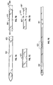
- FIGS. 2( a )-2( b ) respectively show angled and non-angle needles in embodiments of the invention.
- Each figure includes prosthesis 201 .
- Prosthesis 201 e.g., conduit
- Distal fluke 201 has a shoulder such that the ramrod 203 (only shown in FIG. 2( b ) ) may deploy the prosthesis.
- Needle 202 houses prosthesis 201 and ramrod 203 and pierces cardiac tissue. Needle 202 may be straight ( FIG. 2( b ) ), curved ( FIG. 2( a ) ), and/or malleable (to be made straight or curved) allowing the surgeon to choose the appropriate geometry.
- Ramrod 203 deploys the prosthesis when actuated.
- Ramrod 203 is, in an embodiment, hollow and flexible to follow the geometry of the needle, and is concentric to the prosthesis and the long needle.
- Ramrod 203 pushes on a shoulder or other appendage or projection or recess or surface of distal fluke 201 .
- Materials for the ram rod are thin walled stainless steel or nitinol tubing in embodiments.
- a device handle or actuation mechanism allows the surgeon to position and direct the needle into the cardiac tissue, and to deploy the prosthesis when desired.
- the prosthesis is preconfigured with an attachment device (e.g., chord is already located within needle along with, some embodiments, the ramrod), and delivered sterile to the surgeon.
- An embodiment is single use disposable.
- FIGS. 3( a )-3( f ) show various stages of deployment in a process of an embodiment of the invention.
- the surgeon measures the desired length for artificial chordae tendinae, and chooses an attachment device that is preconfigured with a prosthesis of corresponding length.
- Step 2 the surgeon pierces the mitral leaflet at the desired location (for chordal repair) with the distal tip of the attachment device ( FIG. 3( a ) ).
- Step 3 the surgeon pierces the papillary muscle at the desired location (for chordal repair) with the distal tip of the attachment device ( FIG. 3( b ) ).
- Step 4 the surgeon actuates the attachment device (e.g., deploys trigger that advances ramrod or manually pushes on ramrod), which advances the ramrod and deploys the distal end of the prosthesis at the far side of the papillary muscle ( FIG. 3( c ) ).
- Step 5 the surgeon retracts the attachment device out of the papillary muscle.
- a fluke 311 on the distal end of the prosthesis engages the papillary tissue 312 (rotates into position) and prevents the prosthesis from backing out ( FIG. 3( d ) ).
- Step 6 the surgeon continues to retract the attachment device beyond the leaflet 313 ( FIG. 3( e ) ). Once attachment device clears the leaflet, it is discarded.
- Step 7 the surgeon tests valve coaptation with the prosthesis by pressurizing the ventricle with saline.
- a flukes on the proximal end of the prosthesis engages the leaflet (rotates into position) and prevents prosthesis back out ( FIG. 3( f ) ).
- the surgeon may implant additional prostheses if additional chords are desired.
- FIGS. 4( a )-4( c ) shows varying length stages of an adjustable length embodiment of the invention.
- ePTFE suture segments 501 , 505 are knotted, welded, or bonded together outside of flukes.
- Any of the prosthesis designs from the previous figures e.g., FIGS. 1( a )-1( f )
- the surgeon may cut the short ePTFE segment to extend the artificial chord prosthesis overall by some predetermined fixed length ( ⁇ ) (the different between length 520 and 520 ′). Adjustment is performed after implantation, based on saline testing.
- FIG. 5( a ) shows a multi-chord embodiment of the invention.
- FIGS. 5( b )-5( c ) show various stages of deployment of a multi-aperture embodiment of the invention.
- FIG. 5( a ) depicts an adjustable embodiment.
- the embodiment provides a similar delivery needle 502 to that shown in FIG. 2( b ) .
- the prostheses of FIG. 5( a ) is adjustable having chord 1 ( 504 ) and chord 2 ( 504 ′) (which is longer than chord 1 ).
- the ramrod 503 or some similar actuation lever or arm still ejects the distal fluke 510 by abutting a shoulder or other such surface of the fluke.
- the embodiment includes two distal retention members 522 , 523 respectively on chords 1 and 2 (e.g., knots, welds, couplers, heat fused joints).
- chord 1 is not cut the retention member for chord 1 will abut the distal fluke and chord 1 may be deployed in tension when fully extended between the papillary muscle and leaflet. If chord 1 is cut then distal fluke may push the chord 1 retention member distally until the fluke abuts the retention member for chord 2 in addition to or instead of the retention member for chord 1 .
- the distal knot/coupler 526 may allow chords 1 and 2 to pass through it or the distal knot/coupler may be removed in some embodiments.
- the embodiment includes two proximal retention members 524 , 525 (e.g., knots, welds, couplers). If chord 1 is not cut the proximal retention member for chord 1 will abut the proximal fluke.
- proximal fluke 511 may push the chord 1 proximal retention member 527 proximally until the proximal fluke 511 abuts the proximal retention member for chord 2 instead of or in addition to the proximal retention member for chord 1 .
- the proximal knot/coupler may allow chords 1 and 2 to pass through it or may be removed in some embodiments.
- chord 1 retainers 528 may be included in an embodiment such that if chord 1 is cut between the two chord 1 retainers then the chord 1 retainers (in cooperation with the distal and proximal chord 1 retention members) will prevent proximal and distal chord 1 remnants from escaping into the patient's heart/vascular system separate from the implant chord 2 because the chord 1 retainers and chord 1 retention members are sized to not pass through the flukes.
- the distal retention members may be almost or entirely collinear with the chords 1 and 2 within the needle and the same is true for the proximal retention members for chords 1 and 2 .
- This allows for differently sized chords that still maintain a minimal profile to fit within a small diameter needle (i.e., prevents excess slack for chord 2 from jamming within the needle).
- proximal and/or distal couplers may be sized to fit within the flukes (see proximal fluke) or be too large to do so (e.g., see distal fluke) or again, may be omitted altogether.
- chord 1 By trimming chord 1 the length of chord 2 will determine the overall chord length for the patient. If chord 1 is properly sized, chord 2 will remain but will not affect the function of the valve since the chord 1 will be the determining factor in terms of actual function/coupling papillary muscle to leaflet.
- FIGS. 4( a ) and 5( a ) include an adjustable artificial replacement chordae device/system for mitral valve repair. More specifically, an embodiment provides adjustable artificial replacement chordae that allow for variable chordal lengths encountered during valve repair surgery (e.g., mitral valve repair surgery). Such an embodiment allows for a more consistent and simple deployment of replacement chordae.
- FIGS. 4( a ) and 5( a ) allow for adjustment of the artificial chordae once surgically attached to the papillary muscle.
- the mechanisms of the embodiment are simple in that the surgeon is able to make adjustments simply by severing appropriate structures within the device which, as a result of the severing, extend the chordal length a prescribed amount. This contrasts with techniques where the surgeon must manually implant the device, check for proper length, adjust and repeat until proper coaptation has been achieved.
- the chord may be deployed in a manner similar to the system of FIG. 2( b ) .
- other chords such as those shown in FIGS. 1( a )-1( f )
- may be coupled to and through any of the chord apertures see FIG. 5( c ) ) to implant multiple chords into a leaflet with only a single chord traversing the papillary muscle.
- FIGS. 6( a )-6( c ) illustrate various components of a kit in an embodiment of the invention.
- FIG. 6( a ) includes syringe 650 ′
- FIG. 6( b ) includes needle 652 housing a prosthesis with chord 654 and distal and proximal ferules 650 , 661 that abut distal and proximal knots 651 , 655 .
- the prosthesis is preconfigured inside of long needle 652 , and is packaged along with sterile saline syringes (e.g., syringe 650 ′).
- An embodiment includes a kit of between 3-5 needles and saline syringes (single use).
- FIGS. 7( a )-7( e ) illustrate various aspects of a crimped or compressed needle embodiment of the invention.
- the needle is externally crushed over a precision gauge pin, resulting in a short crushed oval section 670 .
- This oval shape presents a restriction to the circular fluke geometry.
- the implant is loaded into needle 652 , and the proximal fluke 661 is forced past the oval section 670 while the distal fluke 650 is loaded into needle 652 before the oval section.
- FIGS. 7( b ) and 7( d ) each shows a side view of section 670 and
- FIG. 7( c ) shows a top view of section 670 .
- FIG. 7( e ) shows one potential location for section 670 but other embodiments may include section 670 nearer either of flukes 650 , 661 .
- FIGS. 8( a )-8( g ) illustrate various stages of deployment of a crimped or compressed needle embodiment of the invention.
- the prosthesis is preloaded in the needle, ready for use ( FIG. 8( a ) ).
- the syringe with sterile saline is then attached to the needle ( FIG. 8( b ) ).
- the needle is primed with saline 871 .
- distal fluke 850 With moderate saline pressure, distal fluke 850 is deployed.
- Proximal fluke 861 is obstructed by oval region 870 and will remain in the needle 852 .
- the proximal fluke 861 cannot be fully deployed with saline pressure.
- light tension on the suture 854 allows the entire prosthesis to be pulled from the needle ( FIGS. 8( d )-8( g ) ).
- a process for implanting a saline deployed embodiment is similar to that of FIGS. 3( a )-3( f ) .
- the surgeon measures the desired length for artificial chordae tendinae, and chooses a needle that is preconfigured with a prosthesis of corresponding length.
- a saline syringe is coupled with the selected needle, and the needle is primed with saline.
- Step 1 the Surgeon pierces the mitral leaflet at the desired location (for chordal repair) with the needle.
- Step 2 the surgeon pierces the papillary muscle at the desired location (for chordal repair) with the needle, and continues until the needle tip emerges on the far side of the papillary.
- step 3 the surgeon applies moderate pressure to the syringe, which advances saline and deploys the distal end of the prosthesis at the far side of the papillary muscle.
- step 4 the surgeon retracts the needle out of the papillary muscle.
- the fluke on distal end of the prosthesis engage (rotates into position) and secures the prosthesis onto the papillary.
- step 5 the surgeon continues to retract the needle beyond the leaflet. Once the needle clears the leaflet, both syringe and needle can be discarded.
- step 6 the surgeon tests valve coaptation with the prosthesis by pressurizing the ventricle with saline.
- the fluke on the proximal end of the prosthesis engage (rotates into position) and secures prosthesis onto leaflet (analogous to FIG. 3( f ) ). Surgeon may repeat the process if additional chords are desired.
- An embodiment employs flukes (e.g., FIG. 3( f ) with or without saline) to enable rapid system deployment.
- the flukes function like a grappling hook or similar coupling member.
- the fluke passes through cardiac tissue in a collapsed state (e.g., FIGS. 3( c )-( d ) with or without saline) and then expands (e.g., rotates to position orthogonal with chord) on the far side of the tissue (e.g., FIGS. 3( d ) and 3( f ) with or without saline) to prevent the fluke and the chord attached thereto from backing out.
- This relieves the surgeon from manually knotting, crimping, and/or tying the prosthesis in place, which ultimately saves operation time.
- the prosthesis is prefabricated and preloaded into the attachment device (deployment tube) (e.g., see FIG. 2( b ) and FIG. 6( b ) ), which again relieves the burden on the surgeon from fabricating and/or loading the prosthesis at the table during surgery.
- deployment tube e.g., see FIG. 2( b ) and FIG. 6( b )
- An embodiment includes a kit that includes multiple chords and deployment tubes in a variety of predetermined lengths, which will allow the surgeon to accurately achieve the correct geometry for that particular patient. This feature eliminates or reduces the variability that comes from a hand-tied prosthesis, and ultimately offers a more consistent product.
- the surgeon may select several tubes to place several prostheses about a single leaflet or multiple leaflets. In such a case the surgeon may simply repeat the process in FIGS. 3( a )-3( f ) (with or without saline) to implant more than one chord.
- the papillary muscle and leaflet are such that they can handle several “pokes” or penetrations by delivery needles to implant chordae, considering the relatively small diameter of the delivery needles.
- the surgeon has an “in-and-out technique” that capitalizes on simplicity and quickness and the ability to deploy 1 or more chordae. For example, three different “shots” or penetrations with delivery needles (to deploy 3 chordae) would be tolerable by papillary muscle and a leaflet.
- the prosthesis that is implanted is comprised entirely of ePTFE and/or PTFE, which allows for excellent biocompatibility and tissue ingrowth into the construct.
- ePTFE and/or PTFE which allows for excellent biocompatibility and tissue ingrowth into the construct.
- other embodiments use other materials for the chord (e.g., nylon) and the fluke of the prosthesis may be fabricated from a polymer or metal (e.g., Nitinol) that allows the fluke to collapse about the chord.
- a polymer or metal e.g., Nitinol
- different versions of those same embodiments may include PTFE or other similar materials.
- embodiments may provide materials with doping.
- the ePTFE and/or PTFE materials described immediately above may be doped with, without limitation, Bismuth.
- the doping agent makes the implant ends radiopaque such that the surgeon can monitor the position of the implant during or after surgery.
- some embodiments include a long needle and a central ramrod which ejects the prosthesis.
- FIG. 2( a ) includes a curved long needle and ramrod.
- FIG. 2( b ) includes a straight long needle and ramrod.
- An embodiment includes a malleable needle which allows the surgeon to bend the needle to achieve the appropriate trajectory of the prosthesis, accounting for differing patient anatomy.
- the needle is flexible and will hold a bend such that the surgeon may position the needle in any orientation or angle to reach differing patient geometries (e.g., the malleable needle and ramrod may be formed into either of the configurations shown in FIGS. 2( a )-2( b ) ).
- the needle is a thin walled metal (e.g., stainless steel or Nitinol).
- the ramrod is similarly a flexible component made of, for example, stainless steel, Nitinol, or a flexible polymer.
- other embodiments are not malleable and may be straight or curved.
- the ramrod of FIG. 2( b ) may be thrust forward or distally by actuation of an actuation mechanism.
- an actuation device may take a number of forms including embodiments employing a scissor grip, pistol grip with trigger, wand with slider, syringe and plunger configuration, any of which can propel the ramrod forward to deploy a chord via one more clicks/actuations of the actuation mechanism.
- An embodiment is used for mitral chordae Tendinae repair/replacement.
- other embodiments may be used in other surgical procedures where it is desirable to anchor two soft tissues together in a rapid manner (e.g., coupling tendon to muscle).
- the orientation of the papillary muscle depends on the individual. Sometimes the muscle is in the base of the heart wall and rises up vertically like a water tower, on others it is on the side of the ventricle and juts out more horizontally. The surgeon may grab the tip of the muscle with forceps and manipulate the muscle to get the preferred orientation for surgery.
- system is a single use disposable attachment device containing a single prosthesis preloaded into the device.
- the system is delivered to the surgeon sterile.
- An embodiment translates to a minimally invasive procedure (e.g., trans-catheter approach or through an intercostal space via transthoracic entry). Since conventional systems require additional instrumentation or surgeon intervention to secure the prosthesis, the conventional systems may have difficulty translating to minimally invasive or trans-catheter deployment. Conventional systems require an open approach and several instruments and components. In contrast, with an embodiment the surgeon inserts one device in to the patient's tissue, clicks the trigger (or flushes syringe), deploys the prosthesis, removes the delivery system, and the surgery is complete.
- FIG. 4( a ) depicts an adjustable embodiment. While the embodiment of FIG. 4( a ) shows the longer and shorter cords joining at or near the knotted ends (or otherwise coupled ends), other embodiments may join the two chords more centrally such that the chords fuse or couple (e.g., by knot, bond, weld, etc.) just proximal to the distal fluke (fluke that abuts papillary muscle) and just distal to the proximal fluke (fluke that abuts leaflet) to ensure the fluke can achieve a small profile while loaded in a delivery needle.
- the chords fuse or couple (e.g., by knot, bond, weld, etc.) just proximal to the distal fluke (fluke that abuts papillary muscle) and just distal to the proximal fluke (fluke that abuts leaflet) to ensure the fluke can achieve a small profile while loaded in a delivery needle.
- the embodiment may include no knot but instead couple the chords to each other with a weld, or the chords may be monolithic with each other where the couple is just a location where the cords couple to each other.
- the chords may be cut or otherwise formed from a single piece of ePTFE.
- a surgeon may anchor a loose ligament or tendon using an embodiment of the system. One end of the system is secured to the free end of the ligament, while the other is anchored in the bone. Based on range of motion desired in the joint, the surgeon then cuts prosthetic segments (e.g., the shorter chord of the adjustable embodiments of FIG. 4( a ) and FIG. 5( a ) ) to achieve the correct length of tendon and the appropriate range of motion.
- the system may constitute a general anchoring or connective prosthesis.
- a pledget may abut the distal fluke and/or proximal fluke to further dissipate stress in addition to the stress dissipation provided by the flukes.
- a pledget is to be interpreted as a buttress or shield to prevent, for example, a suture/coupling member from cutting tissue over time due to repetitive movement of the suture/coupling member.
- Some embodiments include no pledget. Some embodiments allow for a system to be shipped with no pledget but coupled to a pledget at a later time once the shipping container is opened and is ready for use by the surgeon.
- materials are not restricted to ePTFE and/or PTFE and may include, for example (for the chords and/or flukes) silk, nylon, biodegradable materials (e.g., for suturing that is temporary in nature such as is the case with some orthopedic procedures) such as polyglycolic Acid (PGA), polylactic acid (PLA), poly(lactic-co-glycolic acid) (PLGA), polydioxanone (PDS), poly(orthoester) (POE), polycaprolactone (PCL), polymethylmethacrylate (PMMA), copolymer blends of the above, and the like.
- Other embodiments may include biological tissue for chord lengths.
- the system need not be limited to just one material.
- the chords may be PTFE and the flukes may be ePTFE.
- a “fluke” includes objects like conduits or ferrules that pass the chord there through but then anchor the chord by preventing an end of the chord from passing through the fluke.
- a fluke is similar to a “treasury tag” or India tag used to fasten sheets of paper together or to a folder.
- Such a tag includes lace/chord with a tag (e.g., metal or ePTFE) at each end (where the ends are sharpened in some embodiments).
- the tags may be threaded through apertures in documents, tissue, and the like.
- the tag may be orthogonal to the lace upon deployment but in line with the lace while traversing an aperture.
- the tag may have a slot or aperture on one half of the cylinder that comprises the tag such that the lace may move from in-line with the tag to orthogonal to the tag (see FIG. 1( e ) ).
- the lace/chord may or may not be resilient.
- the first and second chords may include separate ePTFE strands joined together via heat (e.g., laser), weld, chemical reaction, and the like.
- Knotless embodiments described herein improve device strength over current methods considering tying knots de-rates/lowers the strength of the base material (e.g., suture/chord).
- the knots introduce stress concentrations, which cause the knot to fail at a smaller load than the base material.
- eliminating/reducing the knots will improve the failure strength of the base material
- Embodiments described herein reduce variability over current methods.
- a current method of hand tying artificial chordae prosthetics out of ePTFE suture requires skill on the part of the surgeon.
- Each knot is comprised of between eight to ten throws in ePTFE suture. The knots could be tied incorrectly or the surgeon could miscount the requisite number of throws resulting in an inferior knot.
- an embodiment eliminates the variability that can be observed in the current method of hand tying artificial chordae prosthetics.
- An embodiment reduces operating room (OR) time compared to current methods. Since the prosthetic is not fabricated during surgery, the duration that the patient is in surgery is reduced.
- a staple or cinch may be coupled to the chord ends.
- a cinch/staple/crimped metal sleeve may be attached to the distal chord ends.
- FIGS. 6( a )-6( c ) please note such an embodiment is suitable for a trans-catheter approach.
- a needle e.g., FIG. 6( c ) , a flexible needle, a jointed needle, conduit
- the needle may couple to a fluid source, which may deploy the chord from the needle based on fluid pressure (e.g., from a plunger).
- fluid pressure e.g., from a plunger
- other embodiments are not so limited and may include inserting the needle through a space between the patient's ribs.
- Example 1 includes an artificial chordae tendonae kit comprising: a hollow first needle including a first proximal end portion having a first proximal aperture, a first distal end portion having a first distal aperture, and a first middle portion coupling the first proximal end portion to the first distal end portion; a flexible first chord coupled to both a first proximal conduit and a first distal conduit; wherein the first proximal end portion includes a first proximal inner diameter directly adjacent the first proximal aperture, the first distal end portion includes a first distal inner diameter directly adjacent the first distal aperture, the first middle portion includes a first narrowed portion with a first middle inner diameter that is less than either of the first proximal inner diameter and the first distal inner diameter; wherein the first chord, the first proximal conduit, and the first distal conduit are all included within the first needle with the first distal conduit distal to the first narrowed portion and the first proximal conduit proximal to the first
- the proximal and distal conduits may include the flukes or ferrules 110 , 111 of FIG. 1( e ) .
- the first middle inner diameter e.g., dimension 681 (marked additionally at 683 )
- the first proximal inner diameter e.g., 680
- the first distal inner diameter e.g., 682
- the dimensions are marked to outer diameters but assuming a consistent wall thickness, a person of ordinary skill in the art will understand the inner diameters would reflect the same relationships among each other as the outer diameters.
- Inner diameters are also marked at 683 ′, 681 ′ in FIG. 7( d ) . In FIGS.
- the long axes of the first proximal and distal conduits are substantially parallel to the long axis of the first needle 285 when the first chord is included within the first needle.
- the first distal conduit is configured to rotate 286 when deployed from the first needle such that the long axis of the first distal conduit 284 is orthogonal to the long axis 288 of the first chord when the first chord is fully extended into a linear orientation (i.e., such as the “linear orientation” shown in FIG. 2( b ) and not in FIG. 6( c ) ).
- Example 2 the subject matter of the Example 1 can optionally include a hollow second needle including a second proximal end portion having a second proximal aperture, a second distal end portion having a second distal aperture, and a second middle portion coupling the second proximal end portion to the second distal end portion; a flexible second chord coupled to both a second proximal conduit and a second distal conduit; wherein the second proximal end portion includes a second proximal inner diameter directly adjacent the second proximal aperture, the second distal end portion includes a second distal inner diameter directly adjacent the second distal aperture, the second middle portion includes a second narrowed portion with a second middle inner diameter that is less than either of the second proximal inner diameter and the second distal inner diameter; wherein the second chord is included within the second needle with the second distal conduit distal to the second narrowed portion and the second proximal conduit proximal to the second narrowed portion; wherein the second needle includes a long axis, the
- the kit may include similarly sized chords. However, the same kit may still have other chords of varying lengths and some kits may have only chords of varying lengths. Embodiments of kits accommodate varying anatomies and preferences of surgeons.
- the subject matter of the Examples 1-2 can optionally include a first proximal obstruction between the first proximal conduit and a proximal end of the first chord; and a first distal obstruction between the first distal conduit and a distal end of the first chord; wherein each of the first proximal and distal obstructions includes an outer diameter greater than an outer diameter of the first chord.
- knots of FIG. 1( a ) include such obstructions.
- Example 4 the subject matter of the Examples 1-3 can optionally include wherein the first chord passes through the first distal conduit.
- the subject matter of the Examples 1-4 can optionally include wherein: the first distal conduit couples to a parabolic portion coupled to a proximal end of the first distal conduit; a first axis, orthogonal to the long axis of the first distal conduit, intersects two portions of the first distal conduit and the first chord; a second axis, orthogonal to the long axis of the first distal conduit, intersects only a single portion of the parabolic portion and the first chord.
- Portion 289 of FIG. 1( h ) constitutes an example of such a parabolic portion.
- the subject matter of the Examples 1-5 can optionally include the first chord passes through the first proximal conduit; the first proximal conduit couples to an additional parabolic portion coupled to a distal end of the first proximal conduit; an additional first axis, orthogonal to the long axis of the first proximal conduit, intersects two portions of the first proximal conduit and the first chord; and an additional second axis, orthogonal to the long axis of the first proximal conduit, intersects only a single portion of the additional parabolic portion and the first chord.
- Example 7 the subject matter of the Examples 1-6 can optionally include a syringe configured to couple to the first proximal aperture of the first needle.
- Example 8 the subject matter of the Examples 1-7 can optionally include wherein the first proximal conduit has an outer diameter that is greater than the first middle inner diameter.
- the outer diameter of the conduit would be greater than the inner diameter 683 ′ of FIG. 7( d ) .
- the subject matter of the Examples 1-8 can optionally include wherein the first distal conduit has an outer diameter that is greater than the first middle inner diameter.
- Example 10 the subject matter of the Examples 1-9 can optionally include wherein at least one of the first proximal and distal conduits are slidably coupled to the first chord.
- conduits of FIG. 2( b ) may slide proximally and distally along the chord.
- the subject matter of the Examples 1-10 can optionally include wherein the first proximal conduit is deformable and configured to deform to slide past the first narrowed portion.
- the proximal conduit may be formed of polytetrafluoroethylene (PTFE) or expanded PTFE (ePTFE) and may deform or compress when passing the narrowed or compresses portion of the needle upon deployment.
- PTFE polytetrafluoroethylene
- ePTFE expanded PTFE
- the subject matter of the Examples 1-11 can optionally include wherein the first chord includes a first chord material, the first proximal conduit includes a first proximal conduit material, and the first distal conduit includes a first distal conduit material that is the same as the first chord material and the first proximal conduit material.
- Example 13 the subject matter of the Examples 1-12 can optionally include wherein the first distal conduit material includes polytetrafluoroethylene.
- Example 14 the subject matter of the Examples 1-13 can optionally include wherein the first narrowed portion is included in a distal third of the first needle.
- this positioning may be within 0.25 inches (6.35 mm) of the distal tip of the needle, such that the chord is within the needle for as long as possible and until the last moment when needle withdraws through the leaflet (e.g., FIG. 3( e ) ).
- Example 15 includes an apparatus comprising: a hollow needle with a narrowed inner diameter in a distal third of the needle; and a flexible chord coupled to proximal and distal conduits; wherein the distal conduit is in the needle and distal to the narrowed inner diameter and the proximal conduit is in the needle and proximal to the narrowed inner diameter; wherein: (a)(i) long axes of the proximal and distal conduits are substantially parallel to a long axis of the needle when the proximal and distal conduits are in the needle, and (a)(ii) the proximal and distal conduits are configured to rotate when deployed from the needle such that their long axes are not parallel to a long axis of the chord when the chord is fully extended.
- Example 16 the subject matter of the Example 15 can optionally include wherein: (b)(i) the chord passes through the proximal and distal conduits, and (b)(ii) the proximal conduit has an outer diameter that is greater than the narrowed inner diameter.
- Example 17 includes an apparatus comprising: a hollow needle; and a flexible chord coupled to compressed proximal and distal anchors; wherein the chord and the proximal and distal anchors are in the needle; wherein the proximal and distal anchors: (a) are compressed when in the needle, and (b) decompressed when deployed from the needle such that each of their decompressed maximum outer diameters is greater than a maximum outer diameter of the needle.
- the anchors may include ePTFE and/or PTFE, which can be compressed within the needle.
- Example 18 the subject matter of the Example 17 can optionally include wherein the proximal and distal anchors each include a shape memory material.
- the shape memory material may include Nitinol.
- the Nitinol may be formed into a helical element that is generally linear in the needle (i.e., in a second shape that is linear and not helical) but resumes its primary state of a helical member once deployed from the needle.
- a pledget may be included adjacent the helical member so the pledget resides between the deployed helical member and the tissue (e.g., papillary muscle, mitral leaflet, or any other tissue).
- the shape memory material may be shape memory polymer (SMP), such as a polyurethane SMP.
- the SMP may have a glass transition temperature near 37-39 degrees Celsius so it resumes its primary “uncompressed” state once deployed from the needle and exposed to body temperature.
- a pledget may be included adjacent the SMP so the pledget resides between the deployed SMP and the tissue (e.g., papillary muscle, mitral leaflet, or any other tissue).
- Example 19 includes a method comprising: providing a hollow needle, with a narrowed inner diameter in a distal third of the needle, and a flexible chord coupled to proximal and distal conduits; wherein (a)(i) the distal conduit is in the needle and distal to the narrowed inner diameter, and the proximal conduit is in the needle and proximal to the narrowed inner diameter; and (a)(ii) long axes of the proximal and distal conduits are substantially parallel to a long axis of the needle; traversing a mitral leaflet with the needle; traversing papillary muscle with the needle while still traversing the mitral leaflet with the needle; deploying the distal conduit from the needle and positioning the distal conduit against a first side of the papillary muscle; retracting the needle from the papillary muscle while leaving a portion of the chord traversing the papillary muscle from the first side of the papillary muscle to a second side of the papillary muscle; retracting the needle from the mitral
- the subject matter of the Examples 19 can optionally include wherein deploying the distal and proximal conduits comprises rotating the distal and proximal conduits so their long axes are not parallel to a long axis of the chord when the chord is fully extended.
- the subject matter of the Examples 19-20 can optionally include wherein deploying the distal conduit comprises injecting a liquid into the needle to force the distal conduit out of the needle.
Abstract
Description
Claims (18)
Priority Applications (2)
| Application Number | Priority Date | Filing Date | Title |
|---|---|---|---|
| US15/013,612 US9480565B2 (en) | 2015-02-02 | 2016-02-02 | Rapid deployment artificial chordae tendinae system |
| US15/334,888 US10213303B2 (en) | 2015-02-02 | 2016-10-26 | Rapid deployment artificial chordae Tendinae system |
Applications Claiming Priority (3)
| Application Number | Priority Date | Filing Date | Title |
|---|---|---|---|
| US201562110666P | 2015-02-02 | 2015-02-02 | |
| US201562237880P | 2015-10-06 | 2015-10-06 | |
| US15/013,612 US9480565B2 (en) | 2015-02-02 | 2016-02-02 | Rapid deployment artificial chordae tendinae system |
Related Child Applications (1)
| Application Number | Title | Priority Date | Filing Date |
|---|---|---|---|
| US15/334,888 Continuation US10213303B2 (en) | 2015-02-02 | 2016-10-26 | Rapid deployment artificial chordae Tendinae system |
Publications (2)
| Publication Number | Publication Date |
|---|---|
| US20160220372A1 US20160220372A1 (en) | 2016-08-04 |
| US9480565B2 true US9480565B2 (en) | 2016-11-01 |
Family
ID=56552686
Family Applications (2)
| Application Number | Title | Priority Date | Filing Date |
|---|---|---|---|
| US15/013,612 Active US9480565B2 (en) | 2015-02-02 | 2016-02-02 | Rapid deployment artificial chordae tendinae system |
| US15/334,888 Active 2036-11-17 US10213303B2 (en) | 2015-02-02 | 2016-10-26 | Rapid deployment artificial chordae Tendinae system |
Family Applications After (1)
| Application Number | Title | Priority Date | Filing Date |
|---|---|---|---|
| US15/334,888 Active 2036-11-17 US10213303B2 (en) | 2015-02-02 | 2016-10-26 | Rapid deployment artificial chordae Tendinae system |
Country Status (2)
| Country | Link |
|---|---|
| US (2) | US9480565B2 (en) |
| WO (1) | WO2016126699A1 (en) |
Cited By (3)
| Publication number | Priority date | Publication date | Assignee | Title |
|---|---|---|---|---|
| US10792036B2 (en) | 2017-11-15 | 2020-10-06 | Winter Innovations, Llc | Method and apparatus for double loop stitching |
| US11103350B2 (en) | 2016-06-01 | 2021-08-31 | On-X Life Technologies, Inc. | Pull-through chordae tendineae system |
| US11213290B2 (en) | 2017-11-15 | 2022-01-04 | Winter Innovations, Inc. | Methods and systems for double loop stitching |
Families Citing this family (24)
| Publication number | Priority date | Publication date | Assignee | Title |
|---|---|---|---|---|
| GB2536538B (en) | 2014-09-17 | 2018-07-18 | Cardiomech As | Anchor for implantation in body tissue |
| CN109771094B (en) * | 2017-11-14 | 2020-12-29 | 杭州德晋医疗科技有限公司 | Artificial chordae tendineae implantation system with position detection device |
| WO2019195860A2 (en) | 2018-04-04 | 2019-10-10 | Vdyne, Llc | Devices and methods for anchoring transcatheter heart valve |
| US11278437B2 (en) | 2018-12-08 | 2022-03-22 | Vdyne, Inc. | Compression capable annular frames for side delivery of transcatheter heart valve replacement |
| US10321995B1 (en) | 2018-09-20 | 2019-06-18 | Vdyne, Llc | Orthogonally delivered transcatheter heart valve replacement |
| US10595994B1 (en) | 2018-09-20 | 2020-03-24 | Vdyne, Llc | Side-delivered transcatheter heart valve replacement |
| US11344413B2 (en) | 2018-09-20 | 2022-05-31 | Vdyne, Inc. | Transcatheter deliverable prosthetic heart valves and methods of delivery |
| US11071627B2 (en) | 2018-10-18 | 2021-07-27 | Vdyne, Inc. | Orthogonally delivered transcatheter heart valve frame for valve in valve prosthesis |
| US11109969B2 (en) | 2018-10-22 | 2021-09-07 | Vdyne, Inc. | Guidewire delivery of transcatheter heart valve |
| US10653522B1 (en) | 2018-12-20 | 2020-05-19 | Vdyne, Inc. | Proximal tab for side-delivered transcatheter heart valve prosthesis |
| US11253359B2 (en) | 2018-12-20 | 2022-02-22 | Vdyne, Inc. | Proximal tab for side-delivered transcatheter heart valves and methods of delivery |
| US11273032B2 (en) | 2019-01-26 | 2022-03-15 | Vdyne, Inc. | Collapsible inner flow control component for side-deliverable transcatheter heart valve prosthesis |
| US11185409B2 (en) | 2019-01-26 | 2021-11-30 | Vdyne, Inc. | Collapsible inner flow control component for side-delivered transcatheter heart valve prosthesis |
| JP2022522411A (en) | 2019-03-05 | 2022-04-19 | ブイダイン,インコーポレイテッド | Tricuspid valve closure regurgitation controller for heart valve prosthesis with orthogonal transcatheter |
| US11076956B2 (en) | 2019-03-14 | 2021-08-03 | Vdyne, Inc. | Proximal, distal, and anterior anchoring tabs for side-delivered transcatheter mitral valve prosthesis |
| US11173027B2 (en) | 2019-03-14 | 2021-11-16 | Vdyne, Inc. | Side-deliverable transcatheter prosthetic valves and methods for delivering and anchoring the same |
| US10631983B1 (en) | 2019-03-14 | 2020-04-28 | Vdyne, Inc. | Distal subannular anchoring tab for side-delivered transcatheter valve prosthesis |
| US10758346B1 (en) | 2019-03-14 | 2020-09-01 | Vdyne, Inc. | A2 clip for side-delivered transcatheter mitral valve prosthesis |
| JP2022526046A (en) * | 2019-03-19 | 2022-05-20 | コアメディック・ゲゼルシャフト・ミット・ベシュレンクテル・ハフツング | A device for repairing the atrioventricular heart valve |
| CN114072106A (en) | 2019-05-04 | 2022-02-18 | 维迪内股份有限公司 | Cinching device and method for deploying a laterally delivered prosthetic heart valve in a native annulus |
| AU2020334080A1 (en) | 2019-08-20 | 2022-03-24 | Vdyne, Inc. | Delivery and retrieval devices and methods for side-deliverable transcatheter prosthetic valves |
| AU2020337235A1 (en) | 2019-08-26 | 2022-03-24 | Vdyne, Inc. | Side-deliverable transcatheter prosthetic valves and methods for delivering and anchoring the same |
| DE202020000044U1 (en) * | 2020-01-02 | 2020-03-31 | Vusal Hajiyev | Anchor for correcting a mitral valve prolapse anchor with central hole for attachment, pulling from the mitral valve sail |
| US11234813B2 (en) | 2020-01-17 | 2022-02-01 | Vdyne, Inc. | Ventricular stability elements for side-deliverable prosthetic heart valves and methods of delivery |
Citations (64)
| Publication number | Priority date | Publication date | Assignee | Title |
|---|---|---|---|---|
| US5307924A (en) * | 1993-03-26 | 1994-05-03 | Abbott Laboratories | Packaging for T-shaped tension devices |
| US5391182A (en) * | 1993-08-03 | 1995-02-21 | Origin Medsystems, Inc. | Apparatus and method for closing puncture wounds |
| US5431666A (en) | 1994-02-24 | 1995-07-11 | Lasersurge, Inc. | Surgical suture instrument |
| US6010531A (en) | 1993-02-22 | 2000-01-04 | Heartport, Inc. | Less-invasive devices and methods for cardiac valve surgery |
| US20020019649A1 (en) * | 1999-12-02 | 2002-02-14 | Smith & Nephew, Inc., Delaware Corporation | Closure device and method for tissue repair |
| US20020068849A1 (en) * | 1997-01-02 | 2002-06-06 | Myocor, Inc. | Heart wall tension reduction apparatus |
| US20020188170A1 (en) * | 2001-04-27 | 2002-12-12 | Santamore William P. | Prevention of myocardial infarction induced ventricular expansion and remodeling |
| US20030105519A1 (en) * | 1997-09-04 | 2003-06-05 | Roland Fasol | Artificial chordae replacement |
| US20040093023A1 (en) * | 1999-10-21 | 2004-05-13 | Allen William J. | Minimally invasive mitral valve repair method and apparatus |
| US6797002B2 (en) | 2000-02-02 | 2004-09-28 | Paul A. Spence | Heart valve repair apparatus and methods |
| US20050038509A1 (en) | 2003-08-14 | 2005-02-17 | Ashe Kassem Ali | Valve prosthesis including a prosthetic leaflet |
| US6869444B2 (en) | 2000-05-22 | 2005-03-22 | Shlomo Gabbay | Low invasive implantable cardiac prosthesis and method for helping improve operation of a heart valve |
| US6945996B2 (en) | 2003-04-18 | 2005-09-20 | Sedransk Kyra L | Replacement mitral valve |
| US6966916B2 (en) | 2002-09-26 | 2005-11-22 | Kumar Sarbjeet S | Device and method for surgical repair of abdominal wall hernias |
| US20050277966A1 (en) * | 2004-06-09 | 2005-12-15 | Usgi Medical Inc. | Compressible tissue anchor assemblies |
| US20050277981A1 (en) * | 2004-06-09 | 2005-12-15 | Usgi Medical Inc. | Apparatus and methods for optimizing anchoring force |
| US20060030885A1 (en) * | 2002-10-15 | 2006-02-09 | Hyde Gregory M | Apparatuses and methods for heart valve repair |
| US6997950B2 (en) | 2003-01-16 | 2006-02-14 | Chawla Surendra K | Valve repair device |
| US20060287716A1 (en) | 2005-06-08 | 2006-12-21 | The Cleveland Clinic Foundation | Artificial chordae |
| US20070049952A1 (en) * | 2005-08-30 | 2007-03-01 | Weiss Steven J | Apparatus and method for mitral valve repair without cardiopulmonary bypass, including transmural techniques |
| US20070051377A1 (en) * | 2003-11-12 | 2007-03-08 | Medtronic Vascular, Inc. | Cardiac valve annulus reduction system |
| US20070073316A1 (en) * | 2001-11-20 | 2007-03-29 | Jean-Claude Sgro | Fastener for fixing a prosthesis, and device for delivering this fastener |
| US20070100375A1 (en) * | 2003-06-06 | 2007-05-03 | Olympus Corporation | Suturing instrument |
| US20070112385A1 (en) * | 2005-11-15 | 2007-05-17 | Conlon Sean P | Expandable suture anchor |
| US20070112338A1 (en) * | 2005-11-01 | 2007-05-17 | Microfabrica Inc. | Microdevices for tissue approximation and retention, methods for using, and methods for making |
| US20070118151A1 (en) * | 2005-11-21 | 2007-05-24 | The Brigham And Women's Hospital, Inc. | Percutaneous cardiac valve repair with adjustable artificial chordae |
| US20070118213A1 (en) * | 2005-11-23 | 2007-05-24 | Didier Loulmet | Methods, devices, and kits for treating mitral valve prolapse |
| US7241257B1 (en) | 2002-06-28 | 2007-07-10 | Abbott Cardiovascular Systems, Inc. | Devices and methods to perform minimally invasive surgeries |
| US20080195126A1 (en) | 2007-02-14 | 2008-08-14 | Jan Otto Solem | Suture and method for repairing a heart |
| US20080208219A1 (en) * | 2007-02-27 | 2008-08-28 | Olympus Medical Systems Corporation | Endoscopic treatment instrument |
| US20080228223A1 (en) * | 2007-03-14 | 2008-09-18 | St. Jude Medical, Inc. | Heart valve chordae replacement methods and apparatus |
| US20080228272A1 (en) | 2006-12-04 | 2008-09-18 | Micardia Corporation | Dynamically adjustable suture and chordae tendinae |
| CA2369641C (en) | 1999-04-09 | 2009-02-10 | Evalve, Inc. | Methods and apparatus for cardiac valve repair |
| US20090043381A1 (en) | 2004-10-05 | 2009-02-12 | Macoviak John A | Atrioventricular valve annulus repair systems and methods including retro-chordal anchors |
| EP2023822A2 (en) | 2006-03-02 | 2009-02-18 | Uros Babic | Catheter based mitral valve repair method and apparatus |
| US20090088837A1 (en) | 2007-09-28 | 2009-04-02 | The Cleveland Clinic Foundation | Prosthetic chordae assembly and method of use |
| US20090177274A1 (en) | 2006-06-07 | 2009-07-09 | Marcio Scorsin | Device for replacing the chordae tendineae of an atrioventricular valve |
| US20090182192A1 (en) * | 2008-01-14 | 2009-07-16 | Olympus Medical Systems Corp. | Treating tool for endoscope |
| US7635386B1 (en) | 2006-03-07 | 2009-12-22 | University Of Maryland, Baltimore | Methods and devices for performing cardiac valve repair |
| US20100023118A1 (en) * | 2008-07-24 | 2010-01-28 | Edwards Lifesciences Corporation | Method and apparatus for repairing or replacing chordae tendinae |
| US20100042147A1 (en) * | 2008-08-14 | 2010-02-18 | Edwards Lifesciences Corporation | Method and apparatus for repairing or replacing chordae tendinae |
| US20100179574A1 (en) | 2009-01-14 | 2010-07-15 | James Longoria | Synthetic chord |
| US20100249919A1 (en) | 2009-03-31 | 2010-09-30 | The Cleveland Clinic Foundation | Pre-sized prosthetic chordae implantation system |
| US7871368B2 (en) | 2006-03-09 | 2011-01-18 | Edwards Lifesciences Corporation | Apparatus, system, and method for applying and adjusting a tensioning element to a hollow body organ |
| US7871433B2 (en) | 2001-12-08 | 2011-01-18 | Lattouf Omar M | Treatments for a patient with congestive heart failure |
| US20110011917A1 (en) | 2008-12-31 | 2011-01-20 | Hansen Medical, Inc. | Methods, devices, and kits for treating valve prolapse |
| US20110060407A1 (en) | 2005-02-07 | 2011-03-10 | Ted Ketai | Methods, systems and devices for cardiac valve repair |
| WO2012040865A1 (en) | 2010-10-01 | 2012-04-05 | Alberto Weber | Medical apparatus and method for heart valve repair |
| WO2012137208A1 (en) | 2011-04-04 | 2012-10-11 | The Medical Research, Infrastructure, And Health Services Fund Of The Tel Aviv Medical Center | Device and method for heart valve repair |
| US8292884B2 (en) | 2002-08-01 | 2012-10-23 | Levine Robert A | Cardiac devices and methods for minimally invasive repair of ischemic mitral regurgitation |
| US8323336B2 (en) | 2008-04-23 | 2012-12-04 | Medtronic, Inc. | Prosthetic heart valve devices and methods of valve replacement |
| US20130006352A1 (en) | 2011-06-29 | 2013-01-03 | Mitralix Ltd. | Heart valve repair devices and methods |
| US8500800B2 (en) | 2009-05-04 | 2013-08-06 | Valtech Cardio Ltd. | Implantation of repair chords in the heart |
| US8545553B2 (en) | 2009-05-04 | 2013-10-01 | Valtech Cardio, Ltd. | Over-wire rotation tool |
| US20130282059A1 (en) | 2005-02-07 | 2013-10-24 | Evalve, Inc. | Methods, systems and devices for cardiac valve repair |
| WO2014009386A1 (en) | 2012-07-09 | 2014-01-16 | Saint-Gobain Glass France | Process box, assembly, and method for processing a coated substrate |
| WO2014028725A1 (en) | 2012-08-17 | 2014-02-20 | On-X Life Technologies, Inc. | Biological chord repair system and methods |
| US20140114404A1 (en) | 2011-06-27 | 2014-04-24 | University Of Maryland, Baltimore | Transapical mitral valve repair device |
| US20140142689A1 (en) * | 2012-11-21 | 2014-05-22 | Didier De Canniere | Device and method of treating heart valve malfunction |
| EP2741711A2 (en) | 2011-08-11 | 2014-06-18 | Tendyne Holdings, Inc. | Improvements for prosthetic valves and related inventions |
| US8758393B2 (en) | 2007-10-18 | 2014-06-24 | Neochord, Inc. | Minimally invasive repair of a valve leaflet in a beating heart |
| US20140364938A1 (en) | 2013-06-05 | 2014-12-11 | Lc Therapeutics, Inc. | Synthetic chord for cardiac valve repair applications |
| AU2015200387A1 (en) | 2010-04-13 | 2015-02-19 | Atricure, Inc. | Methods and devices for accessing and delivering devices to a heart |
| US9060858B2 (en) | 2009-09-15 | 2015-06-23 | Evalve, Inc. | Methods, systems and devices for cardiac valve repair |
Family Cites Families (8)
| Publication number | Priority date | Publication date | Assignee | Title |
|---|---|---|---|---|
| US8425535B2 (en) | 2005-05-20 | 2013-04-23 | Neotract, Inc. | Multi-actuating trigger anchor delivery system |
| US7645286B2 (en) | 2005-05-20 | 2010-01-12 | Neotract, Inc. | Devices, systems and methods for retracting, lifting, compressing, supporting or repositioning tissues or anatomical structures |
| US7758594B2 (en) | 2005-05-20 | 2010-07-20 | Neotract, Inc. | Devices, systems and methods for treating benign prostatic hyperplasia and other conditions |
| US7896891B2 (en) | 2005-05-20 | 2011-03-01 | Neotract, Inc. | Apparatus and method for manipulating or retracting tissue and anatomical structure |
| US8333776B2 (en) | 2005-05-20 | 2012-12-18 | Neotract, Inc. | Anchor delivery system |
| US8157815B2 (en) | 2005-05-20 | 2012-04-17 | Neotract, Inc. | Integrated handle assembly for anchor delivery system |
| EP2345374B1 (en) | 2008-07-30 | 2020-05-20 | Neotract, Inc. | Anchor delivery system with replaceable cartridge |
| WO2014093861A1 (en) | 2012-12-14 | 2014-06-19 | Mayo Foundation For Medical Education And Research | Mitral valve repair devices |
-
2016
- 2016-02-02 WO PCT/US2016/016156 patent/WO2016126699A1/en active Application Filing
- 2016-02-02 US US15/013,612 patent/US9480565B2/en active Active
- 2016-10-26 US US15/334,888 patent/US10213303B2/en active Active
Patent Citations (72)
| Publication number | Priority date | Publication date | Assignee | Title |
|---|---|---|---|---|
| US6010531A (en) | 1993-02-22 | 2000-01-04 | Heartport, Inc. | Less-invasive devices and methods for cardiac valve surgery |
| US20040073301A1 (en) | 1993-02-22 | 2004-04-15 | Donlon Brian S. | Less-invasive devices and methods for cardiac valve surgery |
| US5307924A (en) * | 1993-03-26 | 1994-05-03 | Abbott Laboratories | Packaging for T-shaped tension devices |
| US5391182A (en) * | 1993-08-03 | 1995-02-21 | Origin Medsystems, Inc. | Apparatus and method for closing puncture wounds |
| US5431666A (en) | 1994-02-24 | 1995-07-11 | Lasersurge, Inc. | Surgical suture instrument |
| US20020068849A1 (en) * | 1997-01-02 | 2002-06-06 | Myocor, Inc. | Heart wall tension reduction apparatus |
| US20030105519A1 (en) * | 1997-09-04 | 2003-06-05 | Roland Fasol | Artificial chordae replacement |
| CA2369641C (en) | 1999-04-09 | 2009-02-10 | Evalve, Inc. | Methods and apparatus for cardiac valve repair |
| US20040093023A1 (en) * | 1999-10-21 | 2004-05-13 | Allen William J. | Minimally invasive mitral valve repair method and apparatus |
| US20020019649A1 (en) * | 1999-12-02 | 2002-02-14 | Smith & Nephew, Inc., Delaware Corporation | Closure device and method for tissue repair |
| US6797002B2 (en) | 2000-02-02 | 2004-09-28 | Paul A. Spence | Heart valve repair apparatus and methods |
| US6869444B2 (en) | 2000-05-22 | 2005-03-22 | Shlomo Gabbay | Low invasive implantable cardiac prosthesis and method for helping improve operation of a heart valve |
| US20020188170A1 (en) * | 2001-04-27 | 2002-12-12 | Santamore William P. | Prevention of myocardial infarction induced ventricular expansion and remodeling |
| US20070073316A1 (en) * | 2001-11-20 | 2007-03-29 | Jean-Claude Sgro | Fastener for fixing a prosthesis, and device for delivering this fastener |
| US7871433B2 (en) | 2001-12-08 | 2011-01-18 | Lattouf Omar M | Treatments for a patient with congestive heart failure |
| US8157719B1 (en) | 2002-06-28 | 2012-04-17 | Advanced Cardiovascular Systems, Inc. | Devices and methods to perform minimally invasive surgeries |
| US7241257B1 (en) | 2002-06-28 | 2007-07-10 | Abbott Cardiovascular Systems, Inc. | Devices and methods to perform minimally invasive surgeries |
| US8292884B2 (en) | 2002-08-01 | 2012-10-23 | Levine Robert A | Cardiac devices and methods for minimally invasive repair of ischemic mitral regurgitation |
| US6966916B2 (en) | 2002-09-26 | 2005-11-22 | Kumar Sarbjeet S | Device and method for surgical repair of abdominal wall hernias |
| US20060030885A1 (en) * | 2002-10-15 | 2006-02-09 | Hyde Gregory M | Apparatuses and methods for heart valve repair |
| US6997950B2 (en) | 2003-01-16 | 2006-02-14 | Chawla Surendra K | Valve repair device |
| US6945996B2 (en) | 2003-04-18 | 2005-09-20 | Sedransk Kyra L | Replacement mitral valve |
| US20070100375A1 (en) * | 2003-06-06 | 2007-05-03 | Olympus Corporation | Suturing instrument |
| US20050038509A1 (en) | 2003-08-14 | 2005-02-17 | Ashe Kassem Ali | Valve prosthesis including a prosthetic leaflet |
| US20070051377A1 (en) * | 2003-11-12 | 2007-03-08 | Medtronic Vascular, Inc. | Cardiac valve annulus reduction system |
| US20050277981A1 (en) * | 2004-06-09 | 2005-12-15 | Usgi Medical Inc. | Apparatus and methods for optimizing anchoring force |
| US20050277966A1 (en) * | 2004-06-09 | 2005-12-15 | Usgi Medical Inc. | Compressible tissue anchor assemblies |
| US20090043381A1 (en) | 2004-10-05 | 2009-02-12 | Macoviak John A | Atrioventricular valve annulus repair systems and methods including retro-chordal anchors |
| US20110060407A1 (en) | 2005-02-07 | 2011-03-10 | Ted Ketai | Methods, systems and devices for cardiac valve repair |
| US20130282059A1 (en) | 2005-02-07 | 2013-10-24 | Evalve, Inc. | Methods, systems and devices for cardiac valve repair |
| US20060287716A1 (en) | 2005-06-08 | 2006-12-21 | The Cleveland Clinic Foundation | Artificial chordae |
| US20070049952A1 (en) * | 2005-08-30 | 2007-03-01 | Weiss Steven J | Apparatus and method for mitral valve repair without cardiopulmonary bypass, including transmural techniques |
| US20070112338A1 (en) * | 2005-11-01 | 2007-05-17 | Microfabrica Inc. | Microdevices for tissue approximation and retention, methods for using, and methods for making |
| US20070112385A1 (en) * | 2005-11-15 | 2007-05-17 | Conlon Sean P | Expandable suture anchor |
| US20070118151A1 (en) * | 2005-11-21 | 2007-05-24 | The Brigham And Women's Hospital, Inc. | Percutaneous cardiac valve repair with adjustable artificial chordae |
| US8545551B2 (en) | 2005-11-23 | 2013-10-01 | Hansen Medical, Inc. | Methods, devices, and kits for treating mitral valve prolapse |
| US20070118213A1 (en) * | 2005-11-23 | 2007-05-24 | Didier Loulmet | Methods, devices, and kits for treating mitral valve prolapse |
| EP2023822A2 (en) | 2006-03-02 | 2009-02-18 | Uros Babic | Catheter based mitral valve repair method and apparatus |
| US7635386B1 (en) | 2006-03-07 | 2009-12-22 | University Of Maryland, Baltimore | Methods and devices for performing cardiac valve repair |
| US7871368B2 (en) | 2006-03-09 | 2011-01-18 | Edwards Lifesciences Corporation | Apparatus, system, and method for applying and adjusting a tensioning element to a hollow body organ |
| US20090177274A1 (en) | 2006-06-07 | 2009-07-09 | Marcio Scorsin | Device for replacing the chordae tendineae of an atrioventricular valve |
| US20080228272A1 (en) | 2006-12-04 | 2008-09-18 | Micardia Corporation | Dynamically adjustable suture and chordae tendinae |
| US20080195126A1 (en) | 2007-02-14 | 2008-08-14 | Jan Otto Solem | Suture and method for repairing a heart |
| US20130110230A1 (en) | 2007-02-14 | 2013-05-02 | Edwards Lifesciences Corporation | Suture and method for repairing a heart |
| US20080208219A1 (en) * | 2007-02-27 | 2008-08-28 | Olympus Medical Systems Corporation | Endoscopic treatment instrument |
| US20080228223A1 (en) * | 2007-03-14 | 2008-09-18 | St. Jude Medical, Inc. | Heart valve chordae replacement methods and apparatus |
| US8303622B2 (en) | 2007-03-14 | 2012-11-06 | St. Jude Medical, Inc. | Heart valve chordae replacement methods and apparatus |
| US20090088837A1 (en) | 2007-09-28 | 2009-04-02 | The Cleveland Clinic Foundation | Prosthetic chordae assembly and method of use |
| US8758393B2 (en) | 2007-10-18 | 2014-06-24 | Neochord, Inc. | Minimally invasive repair of a valve leaflet in a beating heart |
| US20090182192A1 (en) * | 2008-01-14 | 2009-07-16 | Olympus Medical Systems Corp. | Treating tool for endoscope |
| US8323336B2 (en) | 2008-04-23 | 2012-12-04 | Medtronic, Inc. | Prosthetic heart valve devices and methods of valve replacement |
| US20130096673A1 (en) | 2008-04-23 | 2013-04-18 | Medtronic, Inc. | Prosthetic Heart Valve Devices And Methods Of Valve Replacement |
| US20100023118A1 (en) * | 2008-07-24 | 2010-01-28 | Edwards Lifesciences Corporation | Method and apparatus for repairing or replacing chordae tendinae |
| US20100042147A1 (en) * | 2008-08-14 | 2010-02-18 | Edwards Lifesciences Corporation | Method and apparatus for repairing or replacing chordae tendinae |
| US8778016B2 (en) | 2008-08-14 | 2014-07-15 | Edwards Lifesciences Corporation | Method and apparatus for repairing or replacing chordae tendinae |
| US20110011917A1 (en) | 2008-12-31 | 2011-01-20 | Hansen Medical, Inc. | Methods, devices, and kits for treating valve prolapse |
| US20100179574A1 (en) | 2009-01-14 | 2010-07-15 | James Longoria | Synthetic chord |
| US8439969B2 (en) | 2009-03-31 | 2013-05-14 | The Cleveland Clinic Foundation | Pre-sized prosthetic chordae implantation system |
| US20100249919A1 (en) | 2009-03-31 | 2010-09-30 | The Cleveland Clinic Foundation | Pre-sized prosthetic chordae implantation system |
| US8500800B2 (en) | 2009-05-04 | 2013-08-06 | Valtech Cardio Ltd. | Implantation of repair chords in the heart |
| US8545553B2 (en) | 2009-05-04 | 2013-10-01 | Valtech Cardio, Ltd. | Over-wire rotation tool |
| US9060858B2 (en) | 2009-09-15 | 2015-06-23 | Evalve, Inc. | Methods, systems and devices for cardiac valve repair |
| AU2015200387A1 (en) | 2010-04-13 | 2015-02-19 | Atricure, Inc. | Methods and devices for accessing and delivering devices to a heart |
| WO2012040865A1 (en) | 2010-10-01 | 2012-04-05 | Alberto Weber | Medical apparatus and method for heart valve repair |
| WO2012137208A1 (en) | 2011-04-04 | 2012-10-11 | The Medical Research, Infrastructure, And Health Services Fund Of The Tel Aviv Medical Center | Device and method for heart valve repair |
| US20140114404A1 (en) | 2011-06-27 | 2014-04-24 | University Of Maryland, Baltimore | Transapical mitral valve repair device |
| US20130006352A1 (en) | 2011-06-29 | 2013-01-03 | Mitralix Ltd. | Heart valve repair devices and methods |
| EP2741711A2 (en) | 2011-08-11 | 2014-06-18 | Tendyne Holdings, Inc. | Improvements for prosthetic valves and related inventions |
| WO2014009386A1 (en) | 2012-07-09 | 2014-01-16 | Saint-Gobain Glass France | Process box, assembly, and method for processing a coated substrate |
| WO2014028725A1 (en) | 2012-08-17 | 2014-02-20 | On-X Life Technologies, Inc. | Biological chord repair system and methods |
| US20140142689A1 (en) * | 2012-11-21 | 2014-05-22 | Didier De Canniere | Device and method of treating heart valve malfunction |
| US20140364938A1 (en) | 2013-06-05 | 2014-12-11 | Lc Therapeutics, Inc. | Synthetic chord for cardiac valve repair applications |
Non-Patent Citations (16)
| Title |
|---|
| "Ti-Knot® Device: Features," LSI Solutions®, Isisolutions.com, Dec 23, 2009, https://web.archive.org/web/20091223024458/http://www.lsisolutions.com/tkfeatures, 2 pages. |
| Bajona, et al. "Beating-heart, off-pump mitral valve repair by implantation of artificial chordae tendineae: an acute in vivo animal study," The Journal of thoracic and cardiovascular surgery 137.1 (2009), 6 pages. |
| Bajona, et al., "Tension measurement of artificial chordae tendinae implanted between the anterior mitral valve leaflet and the left ventricular apex: an in vitro study," Innovations: Technology and Techniques in Cardiothoracic and Vascular Surgery 3.1 (2008), 5 pages. |
| Chiappini, et al., "Replacement of chordae tendineae with polytetrafluoroethylene (PTFE) sutures in mitral valve repair: early and long-term results," Journal of Heart Valve Disease 15.5 (2006), 7 pages. |
| Erickson, Ben, "Testing Wall Anchors and Picture Hangers," todayshomeowner.com, 2008, 8 pages. |
| Farndons Limited, "Solutions," Catalog, http://www.famdons.com/flipbook/Farndons-Catalogue-2015/files/assets/common/downloads/Farndons-Retail-Catalogue-2012.pdf, Feb. 1, 2016, 7 pages. |
| Hongyu Plastic String Co., Limited, "Elastic Rope With Metal Tipping/Elastic Treasury Tag," Online Catalog, http://hysjsd.en.alibaba.com/productlist.html, Jan. 30, 2015, 4 pages. |
| International Searching Authority, "Notification of Transmittal of the International Search Report and the Written Opinion of the International Searching Authority," mailed May 16, 2016 in International application No. PCT/US2016/016156. |
| Ionescu, et al., "Autologous fascia lata for heart valve replacement," Thorax 25.1 (1970), 11 pages. |
| Ionescu, et al., "Mitral valve replacement with aortic heterografts in humans," Thorax 22A (1967), 10 pages. |
| Kendall, "Fixation Device ProTack Pistol Grip 30 Titanium Helical Fasteners," Supreme Med, Mnf #: 174006, http://www.suprememed.com/fixation-device-protack-pistol-grip-30-titanium-helicalfasteners-152138, Feb. 1, 2016, 1 page. |
| Salvador, et al., "A 20-year experience with mitral valve repair with artificial chordae in 608 patients," The Journal of Thoracic and Cardiovascular Surgery 135.6 (2008), 9 pages. |
| Seeburger, et al., "Trans-apical beating-heart implantation of neo-chordae to mitral valve leaflets: results of an acute animal study," European Journal of Cardio-Thoracic Surgery 41.1 (2012): 4 pages. |
| Smallbusinesssupplies.net, "Products: Standard Tag-It 2 Barbs," Small Business Supplies, http://www.smallbusinesssupplies.net/tagging-guns-supplies. |
| Uline, "Long Needle Price Tag Gun / Fasteners," Online Catalog, http://www.uline.com/BL-476/Long-Needle-PriceTag-Gun-Fasteners, Jan. 23, 2015, 1 page. |
| Wikipedia, "Treasury Tag," http://en.wikipedia.org/wiki/Treasury-tag, Jan. 30, 2015, 2 pages. |
Cited By (3)
| Publication number | Priority date | Publication date | Assignee | Title |
|---|---|---|---|---|
| US11103350B2 (en) | 2016-06-01 | 2021-08-31 | On-X Life Technologies, Inc. | Pull-through chordae tendineae system |
| US10792036B2 (en) | 2017-11-15 | 2020-10-06 | Winter Innovations, Llc | Method and apparatus for double loop stitching |
| US11213290B2 (en) | 2017-11-15 | 2022-01-04 | Winter Innovations, Inc. | Methods and systems for double loop stitching |
Also Published As
| Publication number | Publication date |
|---|---|
| US20170105838A1 (en) | 2017-04-20 |
| US10213303B2 (en) | 2019-02-26 |
| US20160220372A1 (en) | 2016-08-04 |
| WO2016126699A1 (en) | 2016-08-11 |
Similar Documents
| Publication | Publication Date | Title |
|---|---|---|
| US10213303B2 (en) | Rapid deployment artificial chordae Tendinae system | |
| US20220039952A1 (en) | Pull-through chordae tendineae system | |
| JP7319021B2 (en) | Medical implants and methods for heart valve repair | |
| US20210236286A1 (en) | Biological Chord Repair System and Methods | |
| US10966830B2 (en) | Medical apparatus and method for heart valve repair | |
| JP6659845B2 (en) | Cardiac tissue anchor | |
| US11696828B2 (en) | Method and apparatus for mitral valve chord repair | |
| CN108289662B (en) | Medical devices and methods for heart valve repair | |
| US8277502B2 (en) | Tissue anchor for annuloplasty device | |
| US20150250590A1 (en) | Transapical mitral chordae replacement | |
| US11903831B2 (en) | Devices, systems, and methods for anchoring an artificial chordae tendineae to a papillary muscle or heart wall | |
| JP2010131404A (en) | Devices and methods for anchoring tissue | |
| CA2671966A1 (en) | Segmented ring placement | |
| US20240065838A1 (en) | Systems and methods for minimally invasive annuloplasty | |
| GB2581545A (en) | Device for heart repair | |
| US20230380969A1 (en) | Method and apparatus for mitral valve chord repair | |
| GB2581863A (en) | Device for heart repair |
Legal Events
| Date | Code | Title | Description |
|---|---|---|---|
| AS | Assignment |
Owner name: ON-X LIFE TECHNOLOGIES, INC., TEXAS Free format text: ASSIGNMENT OF ASSIGNORS INTEREST;ASSIGNORS:MEDEMA, RYAN;SEELEY, MARK;REEL/FRAME:038982/0629 Effective date: 20160621 |
|
| STCF | Information on status: patent grant |
Free format text: PATENTED CASE |
|
| AS | Assignment |
Owner name: DEUTSCHE BANK AG NEW YORK BRANCH, AS COLLATERAL AGENT, NEW YORK Free format text: PATENT SECURITY AGREEMENT;ASSIGNORS:CRYOLIFE, INC.;ON-X LIFE TECHNOLOGIES, INC. (F/K/A MCRI, INC.);REEL/FRAME:044616/0940 Effective date: 20171201 Owner name: DEUTSCHE BANK AG NEW YORK BRANCH, AS COLLATERAL AG Free format text: PATENT SECURITY AGREEMENT;ASSIGNORS:CRYOLIFE, INC.;ON-X LIFE TECHNOLOGIES, INC. (F/K/A MCRI, INC.);REEL/FRAME:044616/0940 Effective date: 20171201 |
|
| MAFP | Maintenance fee payment |
Free format text: PAYMENT OF MAINTENANCE FEE, 4TH YEAR, LARGE ENTITY (ORIGINAL EVENT CODE: M1551); ENTITY STATUS OF PATENT OWNER: LARGE ENTITY Year of fee payment: 4 |
|
| AS | Assignment |
Owner name: ARES CAPITAL CORPORATION, NEW YORK Free format text: SECURITY INTEREST;ASSIGNOR:ON-X LIFE TECHNOLOGIES, INC.;REEL/FRAME:066160/0237 Effective date: 20240118 |
|
| AS | Assignment |
Owner name: ON-X LIFE TECHNOLOGIES, INC., TEXAS Free format text: TERMINATION AND RELEASE OF SECURITY INTEREST IN PATENTS;ASSIGNOR:DEUTSCHE BANK AG NEW YORK BRANCH;REEL/FRAME:066360/0562 Effective date: 20240118 Owner name: CRYOLIFE, INC., GEORGIA Free format text: TERMINATION AND RELEASE OF SECURITY INTEREST IN PATENTS;ASSIGNOR:DEUTSCHE BANK AG NEW YORK BRANCH;REEL/FRAME:066360/0562 Effective date: 20240118 |