US9481301B2 - Vehicle vision system utilizing camera synchronization - Google Patents
Vehicle vision system utilizing camera synchronization Download PDFInfo
- Publication number
- US9481301B2 US9481301B2 US14/097,581 US201314097581A US9481301B2 US 9481301 B2 US9481301 B2 US 9481301B2 US 201314097581 A US201314097581 A US 201314097581A US 9481301 B2 US9481301 B2 US 9481301B2
- Authority
- US
- United States
- Prior art keywords
- vision system
- image sensor
- timing
- ecu
- image
- Prior art date
- Legal status (The legal status is an assumption and is not a legal conclusion. Google has not performed a legal analysis and makes no representation as to the accuracy of the status listed.)
- Active, expires
Links
- 230000001360 synchronised effect Effects 0.000 claims abstract description 26
- 238000000034 method Methods 0.000 claims abstract description 10
- 230000008569 process Effects 0.000 claims abstract description 7
- 239000000872 buffer Substances 0.000 claims description 45
- 238000012545 processing Methods 0.000 claims description 17
- 238000003384 imaging method Methods 0.000 description 22
- 230000033228 biological regulation Effects 0.000 description 7
- 230000008901 benefit Effects 0.000 description 3
- 238000004891 communication Methods 0.000 description 3
- 238000005516 engineering process Methods 0.000 description 3
- 101150052583 CALM1 gene Proteins 0.000 description 2
- 101150114882 CALM2 gene Proteins 0.000 description 2
- 230000008859 change Effects 0.000 description 2
- 238000001514 detection method Methods 0.000 description 2
- 238000004519 manufacturing process Methods 0.000 description 2
- 238000005259 measurement Methods 0.000 description 2
- 230000011664 signaling Effects 0.000 description 2
- 230000004913 activation Effects 0.000 description 1
- 230000005540 biological transmission Effects 0.000 description 1
- 238000004364 calculation method Methods 0.000 description 1
- 238000000576 coating method Methods 0.000 description 1
- 230000003111 delayed effect Effects 0.000 description 1
- 230000001419 dependent effect Effects 0.000 description 1
- 238000013461 design Methods 0.000 description 1
- 230000000694 effects Effects 0.000 description 1
- 238000005286 illumination Methods 0.000 description 1
- 239000004973 liquid crystal related substance Substances 0.000 description 1
- 239000000463 material Substances 0.000 description 1
- 238000012986 modification Methods 0.000 description 1
- 230000004048 modification Effects 0.000 description 1
- 238000012544 monitoring process Methods 0.000 description 1
- 238000012552 review Methods 0.000 description 1
- 238000005096 rolling process Methods 0.000 description 1
- 239000000758 substrate Substances 0.000 description 1
- 239000010409 thin film Substances 0.000 description 1
- 238000012546 transfer Methods 0.000 description 1
Images


Classifications
-
- B—PERFORMING OPERATIONS; TRANSPORTING
- B60—VEHICLES IN GENERAL
- B60R—VEHICLES, VEHICLE FITTINGS, OR VEHICLE PARTS, NOT OTHERWISE PROVIDED FOR
- B60R1/00—Optical viewing arrangements; Real-time viewing arrangements for drivers or passengers using optical image capturing systems, e.g. cameras or video systems specially adapted for use in or on vehicles
-
- H—ELECTRICITY
- H04—ELECTRIC COMMUNICATION TECHNIQUE
- H04N—PICTORIAL COMMUNICATION, e.g. TELEVISION
- H04N5/00—Details of television systems
- H04N5/04—Synchronising
-
- B—PERFORMING OPERATIONS; TRANSPORTING
- B60—VEHICLES IN GENERAL
- B60R—VEHICLES, VEHICLE FITTINGS, OR VEHICLE PARTS, NOT OTHERWISE PROVIDED FOR
- B60R1/00—Optical viewing arrangements; Real-time viewing arrangements for drivers or passengers using optical image capturing systems, e.g. cameras or video systems specially adapted for use in or on vehicles
- B60R1/20—Real-time viewing arrangements for drivers or passengers using optical image capturing systems, e.g. cameras or video systems specially adapted for use in or on vehicles
- B60R1/22—Real-time viewing arrangements for drivers or passengers using optical image capturing systems, e.g. cameras or video systems specially adapted for use in or on vehicles for viewing an area outside the vehicle, e.g. the exterior of the vehicle
- B60R1/23—Real-time viewing arrangements for drivers or passengers using optical image capturing systems, e.g. cameras or video systems specially adapted for use in or on vehicles for viewing an area outside the vehicle, e.g. the exterior of the vehicle with a predetermined field of view
- B60R1/27—Real-time viewing arrangements for drivers or passengers using optical image capturing systems, e.g. cameras or video systems specially adapted for use in or on vehicles for viewing an area outside the vehicle, e.g. the exterior of the vehicle with a predetermined field of view providing all-round vision, e.g. using omnidirectional cameras
-
- G—PHYSICS
- G06—COMPUTING; CALCULATING OR COUNTING
- G06V—IMAGE OR VIDEO RECOGNITION OR UNDERSTANDING
- G06V20/00—Scenes; Scene-specific elements
- G06V20/50—Context or environment of the image
- G06V20/56—Context or environment of the image exterior to a vehicle by using sensors mounted on the vehicle
- G06V20/58—Recognition of moving objects or obstacles, e.g. vehicles or pedestrians; Recognition of traffic objects, e.g. traffic signs, traffic lights or roads
-
- H—ELECTRICITY
- H04—ELECTRIC COMMUNICATION TECHNIQUE
- H04N—PICTORIAL COMMUNICATION, e.g. TELEVISION
- H04N23/00—Cameras or camera modules comprising electronic image sensors; Control thereof
- H04N23/45—Cameras or camera modules comprising electronic image sensors; Control thereof for generating image signals from two or more image sensors being of different type or operating in different modes, e.g. with a CMOS sensor for moving images in combination with a charge-coupled device [CCD] for still images
-
- H—ELECTRICITY
- H04—ELECTRIC COMMUNICATION TECHNIQUE
- H04N—PICTORIAL COMMUNICATION, e.g. TELEVISION
- H04N23/00—Cameras or camera modules comprising electronic image sensors; Control thereof
- H04N23/60—Control of cameras or camera modules
- H04N23/66—Remote control of cameras or camera parts, e.g. by remote control devices
- H04N23/661—Transmitting camera control signals through networks, e.g. control via the Internet
-
- H—ELECTRICITY
- H04—ELECTRIC COMMUNICATION TECHNIQUE
- H04N—PICTORIAL COMMUNICATION, e.g. TELEVISION
- H04N23/00—Cameras or camera modules comprising electronic image sensors; Control thereof
- H04N23/60—Control of cameras or camera modules
- H04N23/698—Control of cameras or camera modules for achieving an enlarged field of view, e.g. panoramic image capture
-
- H—ELECTRICITY
- H04—ELECTRIC COMMUNICATION TECHNIQUE
- H04N—PICTORIAL COMMUNICATION, e.g. TELEVISION
- H04N23/00—Cameras or camera modules comprising electronic image sensors; Control thereof
- H04N23/90—Arrangement of cameras or camera modules, e.g. multiple cameras in TV studios or sports stadiums
-
- H—ELECTRICITY
- H04—ELECTRIC COMMUNICATION TECHNIQUE
- H04N—PICTORIAL COMMUNICATION, e.g. TELEVISION
- H04N25/00—Circuitry of solid-state image sensors [SSIS]; Control thereof
- H04N25/70—SSIS architectures; Circuits associated therewith
- H04N25/76—Addressed sensors, e.g. MOS or CMOS sensors
-
- H04N5/2258—
-
- H04N5/23206—
-
- H—ELECTRICITY
- H04—ELECTRIC COMMUNICATION TECHNIQUE
- H04N—PICTORIAL COMMUNICATION, e.g. TELEVISION
- H04N7/00—Television systems
- H04N7/18—Closed-circuit television [CCTV] systems, i.e. systems in which the video signal is not broadcast
- H04N7/181—Closed-circuit television [CCTV] systems, i.e. systems in which the video signal is not broadcast for receiving images from a plurality of remote sources
-
- B—PERFORMING OPERATIONS; TRANSPORTING
- B60—VEHICLES IN GENERAL
- B60R—VEHICLES, VEHICLE FITTINGS, OR VEHICLE PARTS, NOT OTHERWISE PROVIDED FOR
- B60R2300/00—Details of viewing arrangements using cameras and displays, specially adapted for use in a vehicle
-
- B—PERFORMING OPERATIONS; TRANSPORTING
- B60—VEHICLES IN GENERAL
- B60R—VEHICLES, VEHICLE FITTINGS, OR VEHICLE PARTS, NOT OTHERWISE PROVIDED FOR
- B60R2300/00—Details of viewing arrangements using cameras and displays, specially adapted for use in a vehicle
- B60R2300/10—Details of viewing arrangements using cameras and displays, specially adapted for use in a vehicle characterised by the type of camera system used
- B60R2300/105—Details of viewing arrangements using cameras and displays, specially adapted for use in a vehicle characterised by the type of camera system used using multiple cameras
-
- B—PERFORMING OPERATIONS; TRANSPORTING
- B60—VEHICLES IN GENERAL
- B60R—VEHICLES, VEHICLE FITTINGS, OR VEHICLE PARTS, NOT OTHERWISE PROVIDED FOR
- B60R2300/00—Details of viewing arrangements using cameras and displays, specially adapted for use in a vehicle
- B60R2300/60—Details of viewing arrangements using cameras and displays, specially adapted for use in a vehicle characterised by monitoring and displaying vehicle exterior scenes from a transformed perspective
- B60R2300/607—Details of viewing arrangements using cameras and displays, specially adapted for use in a vehicle characterised by monitoring and displaying vehicle exterior scenes from a transformed perspective from a bird's eye viewpoint
Definitions
- the present invention relates to vehicles with cameras mounted thereon and in particular to vehicles with one or more exterior-facing cameras, such as forward facing cameras and/or sideward facing cameras and/or rearward facing cameras.
- the present invention provides a camera for a vision system that utilizes one or more cameras or image sensors to capture image data of a scene exterior (such as forwardly) of a vehicle and provides a display of images indicative of or representative of the captured image data.
- the vehicle vision system automatically synchronizes a number of cameras of the vision system without changing the system architecture.
- the vehicle vision system powers on or initializes a camera, and starts the camera synchronous to an ECU reference timing, and then regulates the camera timing synchronous to the ECU reference timing.
- the system may adjust or regulate the camera or sensor between a fast mode and a slow mode depending on whether a maximum buffer level achieved during processing exceeds a selected maximum buffer threshold and whether a minimum buffer level achieved during processing is below a selected minimum buffer threshold. By adjusting the mode of the camera or sensor, the system can regulate the camera and synchronize the camera to the ECU timing.
- FIG. 1 is a plan view of a vehicle with a vision system that incorporates cameras in accordance with the present invention
- FIG. 2A is a schematic of a multi-camera system in accordance with the present invention.
- FIG. 2B is a schematic of a multi-camera system with a hub in the path of video data transmission in accordance with the present invention, with some cameras (Cam1 and Cam2) running over the hub and some cameras (CamN) connected to the ECU directly;
- FIG. 3A is a schematic of an ECU structure of the vision system of the present invention, showing on-the-fly image processing without an image buffer, and behind the buffers the image pixels of all of the cameras are clock aligned;
- FIG. 3B is another schematic of an ECU structure of the vision system of the present invention, showing image processing with an image buffer within the pipeline;
- FIG. 4 is a flow chart showing the synchronization main states of the present invention.
- FIG. 5A is a flow chart of a smart camera operation in accordance with the present invention, showing a sequence when starting from reset;
- FIG. 5B is a flow chart of a smart camera operation in accordance with the present invention, showing a sequence when starting from standby;
- FIG. 6 is a flow chart of a regulation of the smart camera of the vision system of the present invention.
- a vehicle 10 includes an imaging system or vision system 12 that includes one or more imaging sensors or cameras (such as a rearward facing imaging sensor or camera 14 a and/or a forwardly facing camera 14 b at the front (or at the windshield) of the vehicle, and/or a sidewardly/rearwardly facing camera 14 c , 14 b at the sides of the vehicle), which capture images exterior of the vehicle, with the cameras having a lens for focusing images at or onto an imaging array or imaging plane of the camera ( FIG. 1 ).
- the vision system 12 is operable to process image data captured by the cameras and may provide displayed images at a display device 16 for viewing by the driver of the vehicle.
- the vision system may process image data to detect objects, such as objects to the rear of the subject or equipped vehicle during a reversing maneuver, or such as approaching or following vehicles or vehicles at a side lane adjacent to the subject or equipped vehicle or the like.
- a typical multi-camera video system as shown in FIG. 2A comprises several (2 to N) satellite cameras, an electronic control unit (ECU) and a display.
- the satellite cameras (such as exterior facing cameras such as cameras 14 a , 14 b , 14 c , 14 d of FIG. 1 ) are connected via a common video interface (such as NTSC (National Television System Committee) or PAL (Phase Alternating Line) or CameraLink or LVDS or the like) and an additional control channel (CAN, LIN, UART) to the ECU.
- Ethernet and LVDS Low Voltage Differential Signaling
- All of the mentioned interfaces are not able to distribute a common clock, generated inside the ECU, to the cameras. Therefore, all of the cameras and the ECU have their own clock sources or timing, although they normally have the same typical clock frequencies.
- the image signal processing uses images that are sensed at the same time to combine them without artifacts to the display output (particularly for generating a surround view display image based on image data captured from multiple exterior viewing cameras of the vehicle). Therefore, the sensors have to run synchronized all the time. This means their frame rates have to be substantially or exactly the same and the sensor readout has to be substantially or nearly at the same video line at a time. They thus typically run synchronously.
- the present invention provides a method that allows the system to synchronize any number of cameras without changing the system architecture. Although only one camera is discussed in the description below, the description applies to all of the cameras of a multi-camera vision system because every camera of a plurality of cameras of the vehicle may be synchronized to an ECU reference timing individually.
- FIG. 2B shows a system that has some cameras (Cam1 and Cam2) connected to and interfacing with a hub (with another camera or other cameras (CamN) connected to and interfacing with the ECU directly.
- the components for realizing the synchronization tasks in the ECU are shown in FIG. 3A .
- the camera video data Cam_Video is coming in to or is received by the Video Line Buffer via the Video Interface controlled by the transfer clock Cam_CLK.
- the side signals Cam_HS and Cam_VS are signaling the line period with blanking (horizontal timing) and frame period with blanking (vertical timing). Data is only written to the Video Line Buffer when Cam_HS and Cam_VS both do not signal a blank phase.
- the Video Line Buffer is organized in a FIFO (first in first out) manner, containing only the pixel data of about 1 to 2 lines or more. This depends of the clock tolerances and how fine the sensor timing can be adjusted.
- the Reference Timing Generator produces the internal pixel reference clock Ref_CLK and timing signals Ref_HS and Ref_VS, which nearly have the same timing properties as the camera signals. If the reference timing signals indicate valid data, the Video Line Buffer is read. Finally, Cam_CLK, Cam_Video, Cam_HS and Cam_VS are replaced by Ref_CLK, Sync_Video, Ref_HS and Ref_VS. This at first has the effect that the camera data path is clock-synchronized to the ECU reference timing.
- the Camera Sync Control instance has to control and ensure that the lines and frames are synchronized. This is achieved by taking care that primarily the camera is started at a well-defined time or timing point, so that the start of the first frame is written to the Video Line Buffer when the reading also starts. Secondly, the camera timing has to be programmed in a manner so that it is definitely a bit faster than the reference timing. This will lead to an increasing Buffer_level of the Video Line Buffer during the frame processing. After some frames, the Buffer_level arrives at a certain upper level threshold c_th_upper, where the camera sensor has to be adjusted to a timing, which is a bit slower than the reference timing. After this, the Buffer_level will decrease frame by frame.
- the threshold values c_th_upper and c_th_lower are constants, which have to be well determined or calculated to avoid a buffer overflow or underflow at all conditions.
- Ref_VS is required to find the right start point for the camera in Camera Sync Control.
- a physical Power Switch on the ECU to control the camera power is not required but may be an optional element of the system.
- the method or system of the present invention also works if camera power is switched somewhere else, such as, for example, by the vehicle ignition or a system activation switch.
- the FIFO or buffer has to equalize only the drifts between the sensor clock and the reference clock during one line. Behind the FIFO, the image alignment still has a drift of about 1-2 lines. This will be solved at the image buffer during the vertical blank period. The main benefit of this solution is the much smaller FIFO.
- the solution with the larger line buffer FIFO may also be used in systems with an image buffer in the pipeline.
- FIG. 3B The input structure for an ECU with an image buffer in the image pipeline is shown in FIG. 3B .
- the Cam_HS and Cam_VS signals are just sampled to the reference clock Ref_CLK and delayed by some clock period or time period. The delay has to be realized in a manner that the active periods of the lines are conserved.
- the FIFO is always empty. When a line starts, it is written from the camera side. Optionally, and desirably, when it is filled about half way, the reading also starts.
- the difference to the solution in FIG. 3A is that Sync_HS and Sync_VS in the system of FIG. 3B are still dependent from the sensor timing and therefore exist in parallel for each camera like Sync_Video.
- the Camera Sync Control is the same in both systems. Instead of the buffer level, there is calculated (in the system of FIG. 3B ) the distance in clock cycles between the start of frame (SOF) of the Reference Timing at Ref_VS and the SOF of the sensor timing at Sync_VS. This is the task of the Calc_Distance block.
- FIG. 4 shows the main tasks in a state-machine depending of the camera power (POWER_on).
- FIG. 5A A flowchart of the start camera task is shown in FIG. 5A .
- the link from ECU to camera is initialized, regardless of which interface technology is used.
- a communication to the camera sensor and optional parts such as, for example, an EEPROM or the like, is established.
- the EEPROM may contain production and calibration data, which is often named intrinsic data. This camera intrinsic data should be read next, because later-on it may be more time consuming or complicated.
- startup time of the sensor is varying from part to part, it may be helpful to measure individual behavior and adjust the start point individually.
- a good period to measure is reset to the start of frame (SOF) or reset to the end of frame (EOF). If this is likely constant, the measurement step with its reset before can be left-out.
- the sensor has to be reconfigured for application specific needs.
- the startup time from the sensor in that case, is different from the startup time with default values after the reset.
- the difference of these two times will be constant for all parts.
- the starting point related to the ECU reference Ref_VS can be calculated, so that the sensor will start its first frame slightly before the ECU wants to read it from the FIFO. The start point is then awaited after the triggering edge of Ref_VS.
- the startup of the sensor is initiated with a reset. This can be done either via hardware (HW), such as by pin toggling or the like, or via software (SW), such as by sending a command or the like. Then the application specific configurations are sent to the sensor, where at its end the sensor has the correct frame timing. At the end of this task, the sensor's start of its first frame will be synchronous with or synchronized to the ECU reference timing and first read.
- HW hardware
- SW software
- FIG. 5B A flowchart of the start camera task is shown in FIG. 5B .
- the link from ECU to camera is initialized, regardless of which interface technology is used.
- a communication to the camera sensor and optional parts, such as, for example, an EEPROM or the like, is established.
- the EEPROM may contain production and calibration data, which is often named intrinsic data. This data should be read next, because later-on it may be more time consuming or complicated to accomplish.
- the senor may be configured with application specific settings or application specific settings may be loaded into the sensor.
- the sensor After that, the sensor has to be put into the standby mode where the application specific settings may not be lost.
- the sensor start timing from standby to run mode may then be measured. If the startup time of the sensor is varying from part to part, it may be helpful to measure individual behavior and adjust the start point individually. A good period to measure is run to start of frame (SOF) or run to end of frame (EOF). If this is likely constant, the measurement step can be left-out.
- SOF start of frame
- EEF run to end of frame
- the start point is then awaited relating to the triggering edge of Ref_VS and the startup of the sensor is initiated by setting the sensor into run mode.
- the sensor's start of first frame will be synchronous to the ECU reference timing and first read.
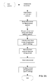
- FIG. 6 A flowchart of the regulation task is shown in FIG. 6 .
- Buffer_Level from FIG. 3A and Distance from FIG. 3B have the same meaning for the Regulation Task.
- the regulation task is a repeating process started once. As described before, the sensor is normally operating a bit faster than the ECU reference timing. This is the fast mode.
- the max_buffer_level is compared to the c_th_upper threshold. If the max buffer level is not greater than the c_th_upper threshold, then the buffer takes no risk to overflow in the next frame and the sensor can continue in fast mode.
- the sensor timing is switched to the slow mode. This is done during the vertical blanking period before the start of frame (SOF).
- the system saves the minimum occurred Buffer_Level in the slow mode to min_buffer_level.
- the min_buffer_level is compared to the c_th_lower threshold. If the minimum buffer level is not smaller than the c_th_lower threshold, then the buffer takes no risk to underflow in the next frame and the sensor can continue in slow mode. Otherwise, if the minimum buffer level is smaller than the threshold, the sensor timing is switched to the fast mode. This is done during the vertical blanking period before SOF. The regulation task then restarts again.
- the regulation task may also operate well if the min_buffer_level is not calculated and checked.
- the fast mode follows one frame period of slow mode automatically. This depends on the adjustment granularity of the sensor and the system design.
- a first option is to add an additional blank line. This enlarges the frame period by one line period. However, if the sensor has a rolling shutter, this method won't work, because it may conflict with the exposure control.
- a second and preferred option is to add blank pixels to the lines.
- the frame period enlarges by the number of lines multiplied with the added pixels per row.
- the exposure control is also influenced, but in a much smoother way, which cannot be recognized by the viewer viewing displayed images captured by the imager and displayed on a display.
- the present invention provides a system that automatically synchronizes a number of cameras of a vehicle vision system without changing the system architecture.
- the system of the present invention powers on or initializes a camera, and starts the camera synchronous to an ECU reference timing, and then regulates the camera timing synchronous to the ECU reference timing.
- the system may adjust or regulate the camera or sensor between a fast mode and a slow mode depending on whether a maximum buffer level achieved during processing exceeds a selected maximum buffer threshold and whether a minimum buffer level achieved during processing is below a selected minimum buffer threshold. By adjusting the mode of the camera or sensor, the system can regulate the camera and synchronize the camera to the ECU timing.
- the vehicle may include any type of sensor or sensors, such as imaging sensors or radar sensors or lidar sensors or ladar sensors or ultrasonic sensors or the like.
- the imaging sensor or camera may capture image data for image processing and may comprise any suitable camera or sensing device, such as, for example, an array of a plurality of photosensor elements arranged in at least 640 columns and 480 rows (preferably a megapixel imaging array or the like), with a respective lens focusing images onto respective portions of the array.
- the photosensor array may comprise a plurality of photosensor elements arranged in a photosensor array having rows and columns.
- the logic and control circuit of the imaging sensor may function in any known manner, and the image processing and algorithmic processing may comprise any suitable means for processing the images and/or image data.
- the vision system and/or processing and/or camera and/or circuitry may utilize aspects described in U.S. Pat. Nos. 7,005,974; 5,760,962; 5,877,897; 5,796,094; 5,949,331; 6,222,447; 6,302,545; 6,396,397; 6,498,620; 6,523,964; 6,611,202; 6,201,642; 6,690,268; 6,717,610; 6,757,109; 6,802,617; 6,806,452; 6,822,563; 6,891,563; 6,946,978; 7,859,565; 5,550,677; 5,670,935; 6,636,258; 7,145,519; 7,161,616; 7,230,640; 7,248,283; 7,295,229; 7,301,466; 7,592,928; 7,881,496; 7,720,580; 7,038,577; 6,882,287; 5,929,786 and/or 5,786,
- 61/754,804 filed Jan. 21, 2013; Ser. No. 61/736,104, filed Dec. 12, 2012; Ser. No. 61/736,103, filed Dec. 12, 2012; Ser. No. 61/734,457, filed Dec. 7, 2012; and/or Ser. No. 61/733,093, filed Dec. 4, 2012, which are all hereby incorporated herein by reference in their entireties.
- the system may communicate with other communication systems via any suitable means, such as by utilizing aspects of the systems described in International Publication Nos. WO/2010/144900; WO 2013/043661 and/or WO 2013/081985, and/or U.S. patent application Ser. No. 13/202,005, filed Aug. 17, 2011, which are hereby incorporated herein by reference in their entireties.
- the imaging device and control and image processor and any associated illumination source may comprise any suitable components, and may utilize aspects of the cameras and vision systems described in U.S. Pat. Nos. 5,550,677; 5,877,897; 6,498,620; 5,670,935; 5,796,094; 6,396,397; 6,806,452; 6,690,268; 7,005,974; 7,123,168; 7,004,606; 6,946,978; 7,038,577; 6,353,392; 6,320,176; 6,313,454; and 6,824,281, and/or International Publication No. WO 2010/099416, published Sep. 2, 2010, and/or PCT Application No. PCT/US10/47256, filed Aug. 31, 2010 and published Mar.
- the camera or cameras may comprise any suitable cameras or imaging sensors or camera modules, and may utilize aspects of the cameras or sensors described in U.S. patent application Ser. No. 12/091,359, filed Apr. 24, 2008 and published Oct. 1, 2009 as U.S.
- the imaging array sensor may comprise any suitable sensor, and may utilize various imaging sensors or imaging array sensors or cameras or the like, such as a CMOS imaging array sensor, a CCD sensor or other sensors or the like, such as the types described in U.S. Pat. Nos.
- the camera module and circuit chip or board and imaging sensor may be implemented and operated in connection with various vehicular vision-based systems, and/or may be operable utilizing the principles of such other vehicular systems, such as a vehicle headlamp control system, such as the type disclosed in U.S. Pat. Nos. 5,796,094; 6,097,023; 6,320,176; 6,559,435; 6,831,261; 7,004,606; 7,339,149; and/or 7,526,103, which are all hereby incorporated herein by reference in their entireties, a rain sensor, such as the types disclosed in commonly assigned U.S. Pat. Nos.
- a vehicle vision system such as a forwardly, sidewardly or rearwardly directed vehicle vision system utilizing principles disclosed in U.S. Pat. Nos.
- a reverse or sideward imaging system such as for a lane change assistance system or lane departure warning system or for a blind spot or object detection system, such as imaging or detection systems of the types disclosed in U.S. Pat. Nos. 7,720,580; 7,038,577; 5,929,786 and/or 5,786,772, and/or U.S. pat. applications, Ser. No. 11/239,980, filed Sep. 30, 2005, now U.S. Pat. No. 7,881,496, and/or U.S. provisional applications, Ser. No. 60/628,709, filed Nov. 17, 2004; Ser. No. 60/614,644, filed Sep. 30, 2004; Ser. No.
- the circuit board or chip may include circuitry for the imaging array sensor and or other electronic accessories or features, such as by utilizing compass-on-a-chip or EC driver-on-a-chip technology and aspects such as described in U.S. Pat. No. 7,255,451 and/or U.S. Pat. No. 7,480,149; and/or U.S. patent applications, Ser. No. 11/226,628, filed Sep. 14, 2005 and published Mar. 23, 2006 as U.S. Publication No. US-2006-0061008, and/or Ser. No. 12/578,732, filed Oct. 14, 2009, which are hereby incorporated herein by reference in their entireties.
- the vision system may include a display for displaying images captured by one or more of the imaging sensors for viewing by the driver of the vehicle while the driver is normally operating the vehicle.
- the vision system may include a video display device disposed at or in the interior rearview mirror assembly of the vehicle, such as by utilizing aspects of the video mirror display systems described in U.S. Pat. No. 6,690,268 and/or U.S. patent application Ser. No. 13/333,337, filed Dec. 21, 2011, which are hereby incorporated herein by reference in their entireties.
- the video mirror display may comprise any suitable devices and systems and optionally may utilize aspects of the compass display systems described in U.S. Pat. Nos.
- the video mirror display screen or device may be operable to display images captured by a rearward viewing camera of the vehicle during a reversing maneuver of the vehicle (such as responsive to the vehicle gear actuator being placed in a reverse gear position or the like) to assist the driver in backing up the vehicle, and optionally may be operable to display the compass heading or directional heading character or icon when the vehicle is not undertaking a reversing maneuver, such as when the vehicle is being driven in a forward direction along a road (such as by utilizing aspects of the display system described in PCT Application No. PCT/US2011/056295, filed Oct. 14, 2011 and published Apr. 19, 2012 as International Publication No. WO 2012/051500, which is hereby incorporated herein by reference in its entirety).
- the vision system (utilizing the forward facing camera and a rearward facing camera and other cameras disposed at the vehicle with exterior fields of view) may be part of or may provide a display of a top-down view or birds-eye view system of the vehicle or a surround view at the vehicle, such as by utilizing aspects of the vision systems described in International Publication Nos. WO 2010/099416; WO 2011/028686; WO2012/075250; WO 2013/019795; WO 2012/075250; WO 2012/145822; WO 2013/081985; WO 2013/086249; and/or WO 2013/109869, and/or U.S. patent application Ser. No. 13/333,337, filed Dec. 21, 2011, which are hereby incorporated herein by reference in their entireties.
- a video mirror display may be disposed rearward of and behind the reflective element assembly and may comprise a display such as the types disclosed in U.S. Pat. Nos. 5,530,240; 6,329,925; 7,855,755; 7,626,749; 7,581,859; 7,446,650; 7,370,983; 7,338,177; 7,274,501; 7,255,451; 7,195,381; 7,184,190; 5,668,663; 5,724,187 and/or 6,690,268, and/or in U.S. patent applications, Ser. No. 12/091,525, filed Apr. 25, 2008, now U.S. Pat. No. 7,855,755; Ser. No. 11/226,628, filed Sep. 14, 2005 and published Mar.
- the display is viewable through the reflective element when the display is activated to display information.
- the display element may be any type of display element, such as a vacuum fluorescent (VF) display element, a light emitting diode (LED) display element, such as an organic light emitting diode (OLED) or an inorganic light emitting diode, an electroluminescent (EL) display element, a liquid crystal display (LCD) element, a video screen display element or backlit thin film transistor (TFT) display element or the like, and may be operable to display various information (as discrete characters, icons or the like, or in a multi-pixel manner) to the driver of the vehicle, such as passenger side inflatable restraint (PSIR) information, tire pressure status, and/or the like.
- PSIR passenger side inflatable restraint
- the mirror assembly and/or display may utilize aspects described in U.S. Pat. Nos.
- the thicknesses and materials of the coatings on the substrates of the reflective element may be selected to provide a desired color or tint to the mirror reflective element, such as a blue colored reflector, such as is known in the art and such as described in U.S. Pat. Nos. 5,910,854; 6,420,036; and/or 7,274,501, which are hereby incorporated herein by reference in their entireties.
- the display or displays and any associated user inputs may be associated with various accessories or systems, such as, for example, a tire pressure monitoring system or a passenger air bag status or a garage door opening system or a telematics system or any other accessory or system of the mirror assembly or of the vehicle or of an accessory module or console of the vehicle, such as an accessory module or console of the types described in U.S. Pat. Nos. 7,289,037; 6,877,888; 6,824,281; 6,690,268; 6,672,744; 6,386,742; and 6,124,886, and/or U.S. patent application Ser. No. 10/538,724, filed Jun. 13, 2005 and published Mar. 9, 2006 as U.S. Publication No. US-2006-0050018, which are hereby incorporated herein by reference in their entireties.
- accessories or systems such as, for example, a tire pressure monitoring system or a passenger air bag status or a garage door opening system or a telematics system or any other accessory or system of the mirror assembly or
Abstract
A vehicular vision system includes an image sensor and an image processor. The image sensor is disposed at a vehicle and has an exterior field of view. The image sensor is operable to capture image data. The image processor is operable to process captured image data. The vision system is operable to automatically synchronize the image sensor to an ECU reference timing. The vision system may power on the image sensor synchronous to the ECU reference timing, and the vision system may regulate the timing of the image sensor synchronous to the ECU reference timing. The vision system may regulate the timing of the image sensor between a fast mode and a slow mode to synchronize the timing of the image sensor to the ECU reference timing.
Description
The present application claims the filing benefits of U.S. provisional application Ser. No. 61/733,598, filed Dec. 5, 2012, which is hereby incorporated herein by reference in its entirety.
The present invention relates to vehicles with cameras mounted thereon and in particular to vehicles with one or more exterior-facing cameras, such as forward facing cameras and/or sideward facing cameras and/or rearward facing cameras.
Use of imaging sensors in vehicle imaging systems is common and known. Examples of such known systems are described in U.S. Pat. Nos. 5,949,331; 5,670,935; and/or 5,550,677, which are hereby incorporated herein by reference in their entireties.
The present invention provides a camera for a vision system that utilizes one or more cameras or image sensors to capture image data of a scene exterior (such as forwardly) of a vehicle and provides a display of images indicative of or representative of the captured image data. The vehicle vision system automatically synchronizes a number of cameras of the vision system without changing the system architecture. The vehicle vision system powers on or initializes a camera, and starts the camera synchronous to an ECU reference timing, and then regulates the camera timing synchronous to the ECU reference timing. The system may adjust or regulate the camera or sensor between a fast mode and a slow mode depending on whether a maximum buffer level achieved during processing exceeds a selected maximum buffer threshold and whether a minimum buffer level achieved during processing is below a selected minimum buffer threshold. By adjusting the mode of the camera or sensor, the system can regulate the camera and synchronize the camera to the ECU timing.
These and other objects, advantages, purposes and features of the present invention will become apparent upon review of the following specification in conjunction with the drawings.
Referring now to the drawings and the illustrative embodiments depicted therein, a vehicle 10 includes an imaging system or vision system 12 that includes one or more imaging sensors or cameras (such as a rearward facing imaging sensor or camera 14 a and/or a forwardly facing camera 14 b at the front (or at the windshield) of the vehicle, and/or a sidewardly/rearwardly facing camera 14 c, 14 b at the sides of the vehicle), which capture images exterior of the vehicle, with the cameras having a lens for focusing images at or onto an imaging array or imaging plane of the camera (FIG. 1 ). The vision system 12 is operable to process image data captured by the cameras and may provide displayed images at a display device 16 for viewing by the driver of the vehicle. Optionally, the vision system may process image data to detect objects, such as objects to the rear of the subject or equipped vehicle during a reversing maneuver, or such as approaching or following vehicles or vehicles at a side lane adjacent to the subject or equipped vehicle or the like.
General Description:
A typical multi-camera video system as shown in FIG. 2A comprises several (2 to N) satellite cameras, an electronic control unit (ECU) and a display. Typically, the satellite cameras (such as exterior facing cameras such as cameras 14 a, 14 b, 14 c, 14 d of FIG. 1 ) are connected via a common video interface (such as NTSC (National Television System Committee) or PAL (Phase Alternating Line) or CameraLink or LVDS or the like) and an additional control channel (CAN, LIN, UART) to the ECU. Ethernet and LVDS (Low Voltage Differential Signaling) may combine the video and the control channel over one interface. All of the mentioned interfaces are not able to distribute a common clock, generated inside the ECU, to the cameras. Therefore, all of the cameras and the ECU have their own clock sources or timing, although they normally have the same typical clock frequencies.
In such a system, it is often desired or required that the image signal processing uses images that are sensed at the same time to combine them without artifacts to the display output (particularly for generating a surround view display image based on image data captured from multiple exterior viewing cameras of the vehicle). Therefore, the sensors have to run synchronized all the time. This means their frame rates have to be substantially or exactly the same and the sensor readout has to be substantially or nearly at the same video line at a time. They thus typically run synchronously.
The present invention provides a method that allows the system to synchronize any number of cameras without changing the system architecture. Although only one camera is discussed in the description below, the description applies to all of the cameras of a multi-camera vision system because every camera of a plurality of cameras of the vehicle may be synchronized to an ECU reference timing individually.
When running the video data over common high performance busses (such as Flexray or the like), there may be hubs instead of an ECU that the cameras are interfacing with and synchronized to. For example, see FIG. 2B , which shows a system that has some cameras (Cam1 and Cam2) connected to and interfacing with a hub (with another camera or other cameras (CamN) connected to and interfacing with the ECU directly. Although only the interfacing to an ECU is discussed in the description below, the present invention and description below applies to both a hub and an ECU as reference timing providing node to the camera or cameras.
ECU Entities for Synchronization:
The components for realizing the synchronization tasks in the ECU are shown in FIG. 3A . The camera video data Cam_Video is coming in to or is received by the Video Line Buffer via the Video Interface controlled by the transfer clock Cam_CLK. The side signals Cam_HS and Cam_VS are signaling the line period with blanking (horizontal timing) and frame period with blanking (vertical timing). Data is only written to the Video Line Buffer when Cam_HS and Cam_VS both do not signal a blank phase. The Video Line Buffer is organized in a FIFO (first in first out) manner, containing only the pixel data of about 1 to 2 lines or more. This depends of the clock tolerances and how fine the sensor timing can be adjusted.
The Reference Timing Generator produces the internal pixel reference clock Ref_CLK and timing signals Ref_HS and Ref_VS, which nearly have the same timing properties as the camera signals. If the reference timing signals indicate valid data, the Video Line Buffer is read. Finally, Cam_CLK, Cam_Video, Cam_HS and Cam_VS are replaced by Ref_CLK, Sync_Video, Ref_HS and Ref_VS. This at first has the effect that the camera data path is clock-synchronized to the ECU reference timing.
Then the Camera Sync Control instance has to control and ensure that the lines and frames are synchronized. This is achieved by taking care that primarily the camera is started at a well-defined time or timing point, so that the start of the first frame is written to the Video Line Buffer when the reading also starts. Secondly, the camera timing has to be programmed in a manner so that it is definitely a bit faster than the reference timing. This will lead to an increasing Buffer_level of the Video Line Buffer during the frame processing. After some frames, the Buffer_level arrives at a certain upper level threshold c_th_upper, where the camera sensor has to be adjusted to a timing, which is a bit slower than the reference timing. After this, the Buffer_level will decrease frame by frame. When the value arrives at a certain lower level threshold c_th_lower, the sensor has to be re-adjusted to the faster timing and so on. The threshold values c_th_upper and c_th_lower are constants, which have to be well determined or calculated to avoid a buffer overflow or underflow at all conditions.
Ref_VS is required to find the right start point for the camera in Camera Sync Control. A physical Power Switch on the ECU to control the camera power is not required but may be an optional element of the system. The method or system of the present invention also works if camera power is switched somewhere else, such as, for example, by the vehicle ignition or a system activation switch.
Synchronization for Image Pipeline with Image Buffer:
In the case where an image buffer is available in the image pipeline, the FIFO or buffer has to equalize only the drifts between the sensor clock and the reference clock during one line. Behind the FIFO, the image alignment still has a drift of about 1-2 lines. This will be solved at the image buffer during the vertical blank period. The main benefit of this solution is the much smaller FIFO. Optionally, the solution with the larger line buffer FIFO (FIG. 3A ) may also be used in systems with an image buffer in the pipeline.
The input structure for an ECU with an image buffer in the image pipeline is shown in FIG. 3B . In this case, the Cam_HS and Cam_VS signals are just sampled to the reference clock Ref_CLK and delayed by some clock period or time period. The delay has to be realized in a manner that the active periods of the lines are conserved. During the blank phases, the FIFO is always empty. When a line starts, it is written from the camera side. Optionally, and desirably, when it is filled about half way, the reading also starts. The difference to the solution in FIG. 3A is that Sync_HS and Sync_VS in the system of FIG. 3B are still dependent from the sensor timing and therefore exist in parallel for each camera like Sync_Video. The Camera Sync Control is the same in both systems. Instead of the buffer level, there is calculated (in the system of FIG. 3B ) the distance in clock cycles between the start of frame (SOF) of the Reference Timing at Ref_VS and the SOF of the sensor timing at Sync_VS. This is the task of the Calc_Distance block.
Camera Sync Control—Main Tasks:
To achieve a multi-camera system running synchronously in accordance with the present invention, two tasks are performed:
1) Start the camera synchronous to the ECU reference timing; and
2) Hold (regulate) the camera timing synchronous to the ECU timing.
Start Camera from Reset Task:
A flowchart of the start camera task is shown in FIG. 5A . After starting or powering-on a camera, the link from ECU to camera is initialized, regardless of which interface technology is used. After the link is initialized, a communication to the camera sensor and optional parts such as, for example, an EEPROM or the like, is established.
The EEPROM may contain production and calibration data, which is often named intrinsic data. This camera intrinsic data should be read next, because later-on it may be more time consuming or complicated.
If the startup time of the sensor is varying from part to part, it may be helpful to measure individual behavior and adjust the start point individually. A good period to measure is reset to the start of frame (SOF) or reset to the end of frame (EOF). If this is likely constant, the measurement step with its reset before can be left-out.
At the end, the sensor has to be reconfigured for application specific needs. The startup time from the sensor, in that case, is different from the startup time with default values after the reset. However, the difference of these two times will be constant for all parts. With knowledge of that time difference or delta time and under consideration of known or selected tolerances, the starting point related to the ECU reference Ref_VS can be calculated, so that the sensor will start its first frame slightly before the ECU wants to read it from the FIFO. The start point is then awaited after the triggering edge of Ref_VS.
The startup of the sensor is initiated with a reset. This can be done either via hardware (HW), such as by pin toggling or the like, or via software (SW), such as by sending a command or the like. Then the application specific configurations are sent to the sensor, where at its end the sensor has the correct frame timing. At the end of this task, the sensor's start of its first frame will be synchronous with or synchronized to the ECU reference timing and first read.
Start Camera from Standby Task:
A flowchart of the start camera task is shown in FIG. 5B . After starting or powering-on a camera, the link from ECU to camera is initialized, regardless of which interface technology is used. After that, a communication to the camera sensor and optional parts, such as, for example, an EEPROM or the like, is established.
The EEPROM may contain production and calibration data, which is often named intrinsic data. This data should be read next, because later-on it may be more time consuming or complicated to accomplish.
Optionally, the sensor may be configured with application specific settings or application specific settings may be loaded into the sensor.
After that, the sensor has to be put into the standby mode where the application specific settings may not be lost. The sensor start timing from standby to run mode may then be measured. If the startup time of the sensor is varying from part to part, it may be helpful to measure individual behavior and adjust the start point individually. A good period to measure is run to start of frame (SOF) or run to end of frame (EOF). If this is likely constant, the measurement step can be left-out.
Then the calculation of the starting point takes place which is related to the ECU reference Ref_VS, so that at the end the sensor will start this first frame slightly before the ECU wants to read it from the FIFO.
The start point is then awaited relating to the triggering edge of Ref_VS and the startup of the sensor is initiated by setting the sensor into run mode. At the end of this task, the sensor's start of first frame will be synchronous to the ECU reference timing and first read.
Regulation Task:
A flowchart of the regulation task is shown in FIG. 6 . Buffer_Level from FIG. 3A and Distance from FIG. 3B have the same meaning for the Regulation Task. The regulation task is a repeating process started once. As described before, the sensor is normally operating a bit faster than the ECU reference timing. This is the fast mode.
While the end of frame (EOF) is awaited, that system saves the maximum occurred Buffer_Level in fast mode to max_buffer_level. After the end of frame (EOF), the max_buffer_level is compared to the c_th_upper threshold. If the max buffer level is not greater than the c_th_upper threshold, then the buffer takes no risk to overflow in the next frame and the sensor can continue in fast mode.
Otherwise, if the max buffer level is greater than the c_th_upper threshold, the sensor timing is switched to the slow mode. This is done during the vertical blanking period before the start of frame (SOF).
While the end of frame is awaited, the system saves the minimum occurred Buffer_Level in the slow mode to min_buffer_level. After EOF, the min_buffer_level is compared to the c_th_lower threshold. If the minimum buffer level is not smaller than the c_th_lower threshold, then the buffer takes no risk to underflow in the next frame and the sensor can continue in slow mode. Otherwise, if the minimum buffer level is smaller than the threshold, the sensor timing is switched to the fast mode. This is done during the vertical blanking period before SOF. The regulation task then restarts again.
Optionally, the regulation task may also operate well if the min_buffer_level is not calculated and checked. In such an application, the fast mode follows one frame period of slow mode automatically. This depends on the adjustment granularity of the sensor and the system design.
Switching Sensor Timing:
In principle, there are two possibilities to slow down the sensor timing. A first option is to add an additional blank line. This enlarges the frame period by one line period. However, if the sensor has a rolling shutter, this method won't work, because it may conflict with the exposure control.
A second and preferred option is to add blank pixels to the lines. In this case the frame period enlarges by the number of lines multiplied with the added pixels per row. In this case, the exposure control is also influenced, but in a much smoother way, which cannot be recognized by the viewer viewing displayed images captured by the imager and displayed on a display.
Therefore, the present invention provides a system that automatically synchronizes a number of cameras of a vehicle vision system without changing the system architecture. The system of the present invention powers on or initializes a camera, and starts the camera synchronous to an ECU reference timing, and then regulates the camera timing synchronous to the ECU reference timing. The system may adjust or regulate the camera or sensor between a fast mode and a slow mode depending on whether a maximum buffer level achieved during processing exceeds a selected maximum buffer threshold and whether a minimum buffer level achieved during processing is below a selected minimum buffer threshold. By adjusting the mode of the camera or sensor, the system can regulate the camera and synchronize the camera to the ECU timing.
The vehicle may include any type of sensor or sensors, such as imaging sensors or radar sensors or lidar sensors or ladar sensors or ultrasonic sensors or the like. The imaging sensor or camera may capture image data for image processing and may comprise any suitable camera or sensing device, such as, for example, an array of a plurality of photosensor elements arranged in at least 640 columns and 480 rows (preferably a megapixel imaging array or the like), with a respective lens focusing images onto respective portions of the array. The photosensor array may comprise a plurality of photosensor elements arranged in a photosensor array having rows and columns. The logic and control circuit of the imaging sensor may function in any known manner, and the image processing and algorithmic processing may comprise any suitable means for processing the images and/or image data.
For example, the vision system and/or processing and/or camera and/or circuitry may utilize aspects described in U.S. Pat. Nos. 7,005,974; 5,760,962; 5,877,897; 5,796,094; 5,949,331; 6,222,447; 6,302,545; 6,396,397; 6,498,620; 6,523,964; 6,611,202; 6,201,642; 6,690,268; 6,717,610; 6,757,109; 6,802,617; 6,806,452; 6,822,563; 6,891,563; 6,946,978; 7,859,565; 5,550,677; 5,670,935; 6,636,258; 7,145,519; 7,161,616; 7,230,640; 7,248,283; 7,295,229; 7,301,466; 7,592,928; 7,881,496; 7,720,580; 7,038,577; 6,882,287; 5,929,786 and/or 5,786,772, and/or International Publication Nos. WO 2011/028686; WO 2010/099416; WO 2012/061567; WO 2012/068331; WO 2012/075250; WO 2012/103193; WO 2012/0116043; WO 2012/0145313; WO 2012/0145501; WO 2012/145818; WO 2012/145822; WO 2012/158167; WO 2012/075250; WO 2012/103193; WO 2012/0116043; WO 2012/0145501; WO 2012/0145343; WO 2012/154919; WO 2013/019707; WO 2013/016409; WO 2012/145822; WO 2013/067083; WO 2013/070539; WO 2013/043661; WO 2013/048994; WO 2013/063014, WO 2013/081984; WO 2013/081985; WO 2013/074604; WO 2013/086249; WO 2013/103548; WO 2013/109869; WO 2013/123161; WO 2013/126715; WO 2013/043661 and/or WO 2013/158592 and/or U.S. patent application Ser. No. 14/082,573, filed Nov. 18, 2013; Ser. No. 14/082,574, filed Nov. 18, 2013; Ser. No. 14/082,575, filed Nov. 18, 2013; Ser. No. 14/082,577, filed Nov. 18, 2013; Ser. No. 14/071,086, filed Nov. 4, 2013; Ser. No. 14/076,524, filed Nov. 11, 2013; Ser. No. 14/052,945, filed Oct. 14, 2013; Ser. No. 14/046,174, filed Oct. 4, 2013; Ser. No. 14/016,790, filed Oct. 3, 2013; Ser. No. 14/036,723, filed Sep. 25, 2013; Ser. No. 14/016,790, filed Sep. 3, 2013; Ser. No. 14/001,272, filed Aug. 23, 2013; Ser. No. 13/970,868, filed Aug. 20, 2013; Ser. No. 13/964,134, filed Aug. 12, 2013; Ser. No. 13/942,758, filed Jul. 16, 2013; Ser. No. 13/942,753, filed Jul. 16, 2013; Ser. No. 13/927,680, filed Jun. 26, 2013; Ser. No. 13/916,051, filed Jun. 12, 2013; Ser. No. 13/894,870, filed May 15, 2013; Ser. No. 13/887,724, filed May 6, 2013; Ser. No. 13/852,190, filed Mar. 28, 2013; Ser. No. 13/851,378, filed Mar. 27, 2013; Ser. No. 13/848,796, filed Mar. 22, 2012; Ser. No. 13/847,815, filed Mar. 20, 2013; Ser. No. 13/800,697, filed Mar. 13, 2013; Ser. No. 13/785,099, filed Mar. 5, 2013; Ser. No. 13/779,881, filed Feb. 28, 2013; Ser. No. 13/774,317, filed Feb. 22, 2013; Ser. No. 13/774,315, filed Feb. 22, 2013; Ser. No. 13/681,963, filed Nov. 20, 2012; Ser. No. 13/660,306, filed Oct. 25, 2012; Ser. No. 13/653,577, filed Oct. 17, 2012; and/or Ser. No. 13/534,657, filed Jun. 27, 2012, and/or U.S. provisional applications, Ser. No. 61/901,127, filed Nov. 7, 2013; Ser. No. 61/905,461, filed Nov. 18, 2013; Ser. No. 61/905,462, filed Nov. 18, 2013; Ser. No. 61/895,610, filed Oct. 25, 2013; Ser. No. 61/895,609, filed Oct. 25, 2013; Ser. No. 61/893,489, filed Oct. 21, 2013; Ser. No. 61/886,883, filed Oct. 4, 2013; Ser. No. 61/879,837, filed Sep. 19, 2013; Ser. No. 61/879,835, filed Sep. 19, 2013; Ser. No. 61/878,877, filed Sep. 17, 2013; Ser. No. 61/875,351, filed Sep. 9, 2013; Ser. No. 61/869,195, filed. Aug. 23, 2013; Ser. No. 61/864,835, filed Aug. 12, 2013; Ser. No. 61/864,836, filed Aug. 12, 2013; Ser. No. 61/864,837, filed Aug. 12, 2013; Ser. No. 61/864,838, filed Aug. 12, 2013; Ser. No. 61/856,843, filed Jul. 22, 2013, Ser. No. 61/845,061, filed Jul. 11, 2013; Ser. No. 61/844,630, filed Jul. 10, 2013; Ser. No. 61/844,173, filed Jul. 9, 2013; Ser. No. 61/844,171, filed Jul. 9, 2013; Ser. No. 61/842,644, filed Jul. 3, 2013; Ser. No. 61/840,542, filed Jun. 28, 2013; Ser. No. 61/838,619, filed Jun. 24, 2013; Ser. No. 61/838,621, filed Jun. 24, 2013; Ser. No. 61/837,955, filed Jun. 21, 2013; Ser. No. 61/836,900, filed Jun. 19, 2013; Ser. No. 61/836,380, filed Jun. 18, 2013; Ser. No. 61/834,129, filed Jun. 12, 2013; Ser. No. 61/833,080, filed Jun. 10, 2013; Ser. No. 61/830,375, filed Jun. 3, 2013; Ser. No. 61/830,377, filed Jun. 3, 2013; Ser. No. 61/825,752, filed May 21, 2013; Ser. No. 61/825,753, filed May 21, 2013; Ser. No. 61/823,648, filed May 15, 2013; Ser. No. 61/823,644, filed May 15, 2013; Ser. No. 61/821,922, filed May 10, 2013; Ser. No. 61/819,835, filed May 6, 2013; Ser. No. 61/819,033, filed May 3, 2013; Ser. No. 61/816,956, filed Apr. 29, 2013; Ser. No. 61/815,044, filed Apr. 23, 2013; Ser. No. 61/814,533, filed Apr. 22, 2013; Ser. No. 61/813,361, filed Apr. 18, 2013; Ser. No. 61/810,407, filed Apr. 10, 2013; Ser. No. 61/808,930, filed Apr. 5, 2013; Ser. No. 61/807,050, filed Apr. 1, 2013; Ser. No. 61/806,674, filed Mar. 29, 2013; Ser. No. 61/793,592, filed Mar. 15, 2013; Ser. No. 61/772,015, filed Mar. 4, 2013; Ser. No. 61/772,014, filed Mar. 4, 2013; Ser. No. 61/770,051, filed Feb. 27, 2013; Ser. No. 61/770,048, filed Feb. 27, 2013; Ser. No. 61/766,883, filed Feb. 20, 2013; Ser. No. 61/760,366, filed Feb. 4, 2013; Ser. No. 61/760,364, filed Feb. 4, 2013; Ser. No. 61/756,832, filed Jan. 25, 2013; Ser. No. 61/754,804, filed Jan. 21, 2013; Ser. No. 61/736,104, filed Dec. 12, 2012; Ser. No. 61/736,103, filed Dec. 12, 2012; Ser. No. 61/734,457, filed Dec. 7, 2012; and/or Ser. No. 61/733,093, filed Dec. 4, 2012, which are all hereby incorporated herein by reference in their entireties. The system may communicate with other communication systems via any suitable means, such as by utilizing aspects of the systems described in International Publication Nos. WO/2010/144900; WO 2013/043661 and/or WO 2013/081985, and/or U.S. patent application Ser. No. 13/202,005, filed Aug. 17, 2011, which are hereby incorporated herein by reference in their entireties.
The imaging device and control and image processor and any associated illumination source, if applicable, may comprise any suitable components, and may utilize aspects of the cameras and vision systems described in U.S. Pat. Nos. 5,550,677; 5,877,897; 6,498,620; 5,670,935; 5,796,094; 6,396,397; 6,806,452; 6,690,268; 7,005,974; 7,123,168; 7,004,606; 6,946,978; 7,038,577; 6,353,392; 6,320,176; 6,313,454; and 6,824,281, and/or International Publication No. WO 2010/099416, published Sep. 2, 2010, and/or PCT Application No. PCT/US10/47256, filed Aug. 31, 2010 and published Mar. 10, 2011 as International Publication No. WO 2011/028686, and/or U.S. patent application Ser. No. 12/508,840, filed Jul. 24, 2009, and published Jan. 28, 2010 as U.S. Pat. Publication No. US 2010-0020170, and/or PCT Application No. PCT/US2012/048110, filed Jul. 25, 2012, and/or U.S. patent application Ser. No. 13/534,657, filed Jun. 27, 2012, which are all hereby incorporated herein by reference in their entireties. The camera or cameras may comprise any suitable cameras or imaging sensors or camera modules, and may utilize aspects of the cameras or sensors described in U.S. patent application Ser. No. 12/091,359, filed Apr. 24, 2008 and published Oct. 1, 2009 as U.S. Publication No. US-2009-0244361, and/or Ser. No. 13/260,400, filed Sep. 26, 2011, and/or U.S. Pat. Nos. 7,965,336 and/or 7,480,149, which are hereby incorporated herein by reference in their entireties. The imaging array sensor may comprise any suitable sensor, and may utilize various imaging sensors or imaging array sensors or cameras or the like, such as a CMOS imaging array sensor, a CCD sensor or other sensors or the like, such as the types described in U.S. Pat. Nos. 5,550,677; 5,670,935; 5,760,962; 5,715,093; 5,877,897; 6,922,292; 6,757,109; 6,717,610; 6,590,719; 6,201,642; 6,498,620; 5,796,094; 6,097,023; 6,320,176; 6,559,435; 6,831,261; 6,806,452; 6,396,397; 6,822,563; 6,946,978; 7,339,149; 7,038,577; 7,004,606; and/or 7,720,580, and/or U.S. patent application Ser. No. 10/534,632, filed May 11, 2005, now U.S. Pat. No. 7,965,336; and/or PCT Application No. PCT/US2008/076022, filed Sep. 11, 2008 and published Mar. 19, 2009 as International Publication No. WO/2009/036176, and/or PCT Application No. PCT/US2008/078700, filed Oct. 3, 2008 and published Apr. 9, 2009 as International Publication No. WO/2009/046268, which are all hereby incorporated herein by reference in their entireties.
The camera module and circuit chip or board and imaging sensor may be implemented and operated in connection with various vehicular vision-based systems, and/or may be operable utilizing the principles of such other vehicular systems, such as a vehicle headlamp control system, such as the type disclosed in U.S. Pat. Nos. 5,796,094; 6,097,023; 6,320,176; 6,559,435; 6,831,261; 7,004,606; 7,339,149; and/or 7,526,103, which are all hereby incorporated herein by reference in their entireties, a rain sensor, such as the types disclosed in commonly assigned U.S. Pat. Nos. 6,353,392; 6,313,454; 6,320,176; and/or 7,480,149, which are hereby incorporated herein by reference in their entireties, a vehicle vision system, such as a forwardly, sidewardly or rearwardly directed vehicle vision system utilizing principles disclosed in U.S. Pat. Nos. 5,550,677; 5,670,935; 5,760,962; 5,877,897; 5,949,331; 6,222,447; 6,302,545; 6,396,397; 6,498,620; 6,523,964; 6,611,202; 6,201,642; 6,690,268; 6,717,610; 6,757,109; 6,802,617; 6,806,452; 6,822,563; 6,891,563; 6,946,978; and/or 7,859,565, which are all hereby incorporated herein by reference in their entireties, a trailer hitching aid or tow check system, such as the type disclosed in U.S. Pat. No. 7,005,974, which is hereby incorporated herein by reference in its entirety, a reverse or sideward imaging system, such as for a lane change assistance system or lane departure warning system or for a blind spot or object detection system, such as imaging or detection systems of the types disclosed in U.S. Pat. Nos. 7,720,580; 7,038,577; 5,929,786 and/or 5,786,772, and/or U.S. pat. applications, Ser. No. 11/239,980, filed Sep. 30, 2005, now U.S. Pat. No. 7,881,496, and/or U.S. provisional applications, Ser. No. 60/628,709, filed Nov. 17, 2004; Ser. No. 60/614,644, filed Sep. 30, 2004; Ser. No. 60/618,686, filed Oct. 14, 2004; Ser. No. 60/638,687, filed Dec. 23, 2004, which are hereby incorporated herein by reference in their entireties, a video device for internal cabin surveillance and/or video telephone function, such as disclosed in U.S. Pat. Nos. 5,760,962; 5,877,897; 6,690,268; and/or 7,370,983, and/or U.S. patent application Ser. No. 10/538,724, filed Jun. 13, 2005 and published Mar. 9, 2006 as U.S. Publication No. US-2006-0050018, which are hereby incorporated herein by reference in their entireties, a traffic sign recognition system, a system for determining a distance to a leading or trailing vehicle or object, such as a system utilizing the principles disclosed in U.S. Pat. Nos. 6,396,397 and/or 7,123,168, which are hereby incorporated herein by reference in their entireties, and/or the like.
Optionally, the circuit board or chip may include circuitry for the imaging array sensor and or other electronic accessories or features, such as by utilizing compass-on-a-chip or EC driver-on-a-chip technology and aspects such as described in U.S. Pat. No. 7,255,451 and/or U.S. Pat. No. 7,480,149; and/or U.S. patent applications, Ser. No. 11/226,628, filed Sep. 14, 2005 and published Mar. 23, 2006 as U.S. Publication No. US-2006-0061008, and/or Ser. No. 12/578,732, filed Oct. 14, 2009, which are hereby incorporated herein by reference in their entireties.
Optionally, the vision system may include a display for displaying images captured by one or more of the imaging sensors for viewing by the driver of the vehicle while the driver is normally operating the vehicle. Optionally, for example, the vision system may include a video display device disposed at or in the interior rearview mirror assembly of the vehicle, such as by utilizing aspects of the video mirror display systems described in U.S. Pat. No. 6,690,268 and/or U.S. patent application Ser. No. 13/333,337, filed Dec. 21, 2011, which are hereby incorporated herein by reference in their entireties. The video mirror display may comprise any suitable devices and systems and optionally may utilize aspects of the compass display systems described in U.S. Pat. Nos. 7,370,983; 7,329,013; 7,308,341; 7,289,037; 7,249,860; 7,004,593; 4,546,551; 5,699,044; 4,953,305; 5,576,687; 5,632,092; 5,677,851; 5,708,410; 5,737,226; 5,802,727; 5,878,370; 6,087,953; 6,173,508; 6,222,460; 6,513,252; and/or 6,642,851, and/or European patent application, published Oct. 11, 2000 under Publication No. EP 0 1043566, and/or U.S. patent application Ser. No. 11/226,628, filed Sep. 14, 2005 and published Mar. 23, 2006 as U.S. Publication No. US-2006-0061008, which are all hereby incorporated herein by reference in their entireties. Optionally, the video mirror display screen or device may be operable to display images captured by a rearward viewing camera of the vehicle during a reversing maneuver of the vehicle (such as responsive to the vehicle gear actuator being placed in a reverse gear position or the like) to assist the driver in backing up the vehicle, and optionally may be operable to display the compass heading or directional heading character or icon when the vehicle is not undertaking a reversing maneuver, such as when the vehicle is being driven in a forward direction along a road (such as by utilizing aspects of the display system described in PCT Application No. PCT/US2011/056295, filed Oct. 14, 2011 and published Apr. 19, 2012 as International Publication No. WO 2012/051500, which is hereby incorporated herein by reference in its entirety).
Optionally, the vision system (utilizing the forward facing camera and a rearward facing camera and other cameras disposed at the vehicle with exterior fields of view) may be part of or may provide a display of a top-down view or birds-eye view system of the vehicle or a surround view at the vehicle, such as by utilizing aspects of the vision systems described in International Publication Nos. WO 2010/099416; WO 2011/028686; WO2012/075250; WO 2013/019795; WO 2012/075250; WO 2012/145822; WO 2013/081985; WO 2013/086249; and/or WO 2013/109869, and/or U.S. patent application Ser. No. 13/333,337, filed Dec. 21, 2011, which are hereby incorporated herein by reference in their entireties.
Optionally, a video mirror display may be disposed rearward of and behind the reflective element assembly and may comprise a display such as the types disclosed in U.S. Pat. Nos. 5,530,240; 6,329,925; 7,855,755; 7,626,749; 7,581,859; 7,446,650; 7,370,983; 7,338,177; 7,274,501; 7,255,451; 7,195,381; 7,184,190; 5,668,663; 5,724,187 and/or 6,690,268, and/or in U.S. patent applications, Ser. No. 12/091,525, filed Apr. 25, 2008, now U.S. Pat. No. 7,855,755; Ser. No. 11/226,628, filed Sep. 14, 2005 and published Mar. 23, 2006 as U.S. Publication No. US-2006-0061008; and/or Ser. No. 10/538,724, filed Jun. 13, 2005 and published Mar. 9, 2006 as U.S. Publication No. US-2006-0050018, which are all hereby incorporated herein by reference in their entireties. The display is viewable through the reflective element when the display is activated to display information. The display element may be any type of display element, such as a vacuum fluorescent (VF) display element, a light emitting diode (LED) display element, such as an organic light emitting diode (OLED) or an inorganic light emitting diode, an electroluminescent (EL) display element, a liquid crystal display (LCD) element, a video screen display element or backlit thin film transistor (TFT) display element or the like, and may be operable to display various information (as discrete characters, icons or the like, or in a multi-pixel manner) to the driver of the vehicle, such as passenger side inflatable restraint (PSIR) information, tire pressure status, and/or the like. The mirror assembly and/or display may utilize aspects described in U.S. Pat. Nos. 7,184,190; 7,255,451; 7,446,924 and/or 7,338,177, which are all hereby incorporated herein by reference in their entireties. The thicknesses and materials of the coatings on the substrates of the reflective element may be selected to provide a desired color or tint to the mirror reflective element, such as a blue colored reflector, such as is known in the art and such as described in U.S. Pat. Nos. 5,910,854; 6,420,036; and/or 7,274,501, which are hereby incorporated herein by reference in their entireties.
Optionally, the display or displays and any associated user inputs may be associated with various accessories or systems, such as, for example, a tire pressure monitoring system or a passenger air bag status or a garage door opening system or a telematics system or any other accessory or system of the mirror assembly or of the vehicle or of an accessory module or console of the vehicle, such as an accessory module or console of the types described in U.S. Pat. Nos. 7,289,037; 6,877,888; 6,824,281; 6,690,268; 6,672,744; 6,386,742; and 6,124,886, and/or U.S. patent application Ser. No. 10/538,724, filed Jun. 13, 2005 and published Mar. 9, 2006 as U.S. Publication No. US-2006-0050018, which are hereby incorporated herein by reference in their entireties.
While the above description constitutes a plurality of embodiments of the present invention, it will be appreciated that the present invention is susceptible to further modification and change without departing from the fair meaning of the accompanying claims.
Claims (14)
1. A vehicular vision system, said vehicular vision system comprising:
an image sensor disposed at a vehicle and having an exterior field of view, wherein said image sensor is operable to capture image data;
an image processor operable to process captured image data;
an electronic control unit (ECU);
wherein said vision system is operable to automatically synchronize said image sensor to reference timing of said ECU;
wherein said vision system regulates said image sensor between a fast mode and a slow mode, and wherein said vision system regulates said image sensor between said fast mode and said slow mode depending on whether a maximum buffer level achieved during processing of captured image data by said image processor exceeds a selected maximum buffer threshold; and
wherein said vision system switches the timing of said image sensor to the slow mode when the maximum buffer level is greater than the selected maximum buffer threshold, and wherein said vision system switches the timing of said image sensor to the fast mode when the minimum buffer level is below the selected minimum buffer threshold.
2. The vehicular vision system of claim 1 , wherein said vision system is operable to power on said image sensor synchronous to the reference timing of said ECU.
3. The vehicular vision system of claim 1 , wherein said vision system is operable to regulate the timing of said image sensor synchronous to the reference timing of said ECU.
4. The vehicular vision system of claim 3 , wherein said vision system regulates the timing of said image sensor between the fast mode and the slow mode to synchronize the timing of said image sensor to the reference timing of said ECU.
5. The vehicular vision system of claim 1 , comprising a plurality of image sensors.
6. The vehicular vision system of claim 5 , wherein each of said plurality of image sensors is synchronized automatically and independently via a respective control signal to the reference timing of said ECU.
7. The vehicular vision system of claim 5 , comprising a hub in the path of image data captured by at least some of said plurality of image sensors to said ECU.
8. The vehicular vision system of claim 7 , wherein each of said at least some of said plurality of image sensors is synchronized automatically and independently via a respective control signal to a hub reference timing.
9. A vehicular vision system, said vehicular vision system comprising:
an image sensor disposed at a vehicle and having an exterior field of view, wherein said image sensor is operable to capture image data;
an image processor operable to process captured image data;
an electronic control unit (ECU);
wherein said vision system is operable to automatically synchronize said image sensor to reference timing of said ECU;
wherein said vision system is operable to power on said image sensor synchronous to the ECU reference timing;
wherein said vision system is operable to regulate the timing of said image sensor synchronous to the reference timing of said ECU;
wherein said vision system regulates said image sensor between a fast mode and a slow mode, and wherein said vision system regulates said image sensor between said fast mode and said slow mode depending on whether a maximum buffer level achieved during processing of captured image data by said image processor exceeds a selected maximum buffer threshold; and
wherein said vision system switches the timing of said image sensor to the slow mode when the maximum buffer level is greater than the selected maximum buffer threshold, and wherein said vision system switches the timing of said image sensor to the fast mode when the minimum buffer level is below the selected minimum buffer threshold.
10. The vehicular vision system of claim 9 , wherein said vision system regulates the timing of said image sensor between the fast mode and the slow mode to synchronize the timing of said image sensor to the reference timing of said ECU.
11. The vehicular vision system of claim 9 , comprising a plurality of image sensors, and wherein each of said plurality of image sensors is synchronized automatically and independently via a respective control signal to the reference timing of said ECU.
12. A vehicular vision system, said vehicular vision system comprising:
a plurality of image sensors disposed at a vehicle and having respective exterior fields of view;
wherein said plurality of image sensors comprises at least one first image sensor that interfaces directly with an electronic control unit (ECU);
wherein said plurality of image sensors comprises second image sensors that interface with a hub disposed in the path of captured image data captured from said second image sensors to said ECU;
wherein said first and second image sensors are operable to capture image data;
an image processor operable to process captured image data;
wherein said vision system is operable to automatically synchronize said first and second image sensors to reference timing of said ECU;
wherein said at least one first image sensor is synchronized automatically and independently via a respective control signal for each said at least one first image sensor to the reference timing of said ECU;
wherein said second image sensors are synchronized automatically and independently via a respective control signal for each said second image sensors to a hub reference timing;
wherein said vision system regulates said image sensor between a fast mode and a slow mode, and wherein said vision system regulates said image sensor between said fast mode and said slow mode depending on whether a maximum buffer level achieved during processing of captured image data by said image processor exceeds a selected maximum buffer threshold and whether a minimum buffer level achieved during processing of captured image data by said image processor is below a selected minimum buffer threshold; and
wherein said vision system switches the timing of said image sensor to the slow mode when the maximum buffer level is greater than the selected maximum buffer threshold, and wherein said vision system switches the timing of said image sensor to the fast mode when the minimum buffer level is below the selected minimum buffer threshold.
13. The vehicular vision system of claim 12 , wherein said vision system is operable to power on said image sensors synchronous to the reference timing of said ECU, and wherein said vision system is operable to regulate the timing of said image sensors synchronous to the reference timing of said ECU.
14. The vehicular vision system of claim 13 , wherein said vision system regulates the timing of each image sensor between the fast mode and the slow mode to synchronize the timing of said image sensor to the reference timing of said ECU.
Priority Applications (5)
| Application Number | Priority Date | Filing Date | Title |
|---|---|---|---|
| US14/097,581 US9481301B2 (en) | 2012-12-05 | 2013-12-05 | Vehicle vision system utilizing camera synchronization |
| US15/338,781 US9912841B2 (en) | 2012-12-05 | 2016-10-31 | Vehicle vision system utilizing camera synchronization |
| US15/911,442 US10171709B2 (en) | 2012-12-05 | 2018-03-05 | Vehicle vision system utilizing multiple cameras and ethernet links |
| US16/234,766 US10560610B2 (en) | 2012-12-05 | 2018-12-28 | Method of synchronizing multiple vehicular cameras with an ECU |
| US16/785,825 US10873682B2 (en) | 2012-12-05 | 2020-02-10 | Method of synchronizing multiple vehicular cameras with an ECU |
Applications Claiming Priority (2)
| Application Number | Priority Date | Filing Date | Title |
|---|---|---|---|
| US201261733598P | 2012-12-05 | 2012-12-05 | |
| US14/097,581 US9481301B2 (en) | 2012-12-05 | 2013-12-05 | Vehicle vision system utilizing camera synchronization |
Related Child Applications (1)
| Application Number | Title | Priority Date | Filing Date |
|---|---|---|---|
| US15/338,781 Continuation US9912841B2 (en) | 2012-12-05 | 2016-10-31 | Vehicle vision system utilizing camera synchronization |
Publications (2)
| Publication Number | Publication Date |
|---|---|
| US20140160291A1 US20140160291A1 (en) | 2014-06-12 |
| US9481301B2 true US9481301B2 (en) | 2016-11-01 |
Family
ID=50880551
Family Applications (5)
| Application Number | Title | Priority Date | Filing Date |
|---|---|---|---|
| US14/097,581 Active 2034-11-09 US9481301B2 (en) | 2012-12-05 | 2013-12-05 | Vehicle vision system utilizing camera synchronization |
| US15/338,781 Active US9912841B2 (en) | 2012-12-05 | 2016-10-31 | Vehicle vision system utilizing camera synchronization |
| US15/911,442 Active US10171709B2 (en) | 2012-12-05 | 2018-03-05 | Vehicle vision system utilizing multiple cameras and ethernet links |
| US16/234,766 Active US10560610B2 (en) | 2012-12-05 | 2018-12-28 | Method of synchronizing multiple vehicular cameras with an ECU |
| US16/785,825 Active US10873682B2 (en) | 2012-12-05 | 2020-02-10 | Method of synchronizing multiple vehicular cameras with an ECU |
Family Applications After (4)
| Application Number | Title | Priority Date | Filing Date |
|---|---|---|---|
| US15/338,781 Active US9912841B2 (en) | 2012-12-05 | 2016-10-31 | Vehicle vision system utilizing camera synchronization |
| US15/911,442 Active US10171709B2 (en) | 2012-12-05 | 2018-03-05 | Vehicle vision system utilizing multiple cameras and ethernet links |
| US16/234,766 Active US10560610B2 (en) | 2012-12-05 | 2018-12-28 | Method of synchronizing multiple vehicular cameras with an ECU |
| US16/785,825 Active US10873682B2 (en) | 2012-12-05 | 2020-02-10 | Method of synchronizing multiple vehicular cameras with an ECU |
Country Status (1)
| Country | Link |
|---|---|
| US (5) | US9481301B2 (en) |
Cited By (6)
| Publication number | Priority date | Publication date | Assignee | Title |
|---|---|---|---|---|
| US20160267725A1 (en) * | 2012-03-01 | 2016-09-15 | Magna Electronics Inc. | Process for determining state of a vehicle |
| US9912841B2 (en) | 2012-12-05 | 2018-03-06 | Magna Electronics Inc. | Vehicle vision system utilizing camera synchronization |
| US10531075B1 (en) | 2018-09-27 | 2020-01-07 | Honda Motor Co., Ltd. | Synchronization controller unit for sensor node |
| US10958830B2 (en) | 2018-05-24 | 2021-03-23 | Magna Electronics Inc. | Vehicle vision system with infrared LED synchronization |
| US20210123777A1 (en) * | 2019-10-24 | 2021-04-29 | Hyundai Mobis Co., Ltd. | Automotive sensor integration module |
| US11180117B2 (en) * | 2019-08-31 | 2021-11-23 | Light Labs Inc. | Methods and apparatus for capturing and using images in a system including wipers |
Families Citing this family (30)
| Publication number | Priority date | Publication date | Assignee | Title |
|---|---|---|---|---|
| DE112012003931T5 (en) | 2011-09-21 | 2014-07-10 | Magna Electronics, Inc. | Image processing system for a motor vehicle with image data transmission and power supply via a coaxial cable |
| WO2013081985A1 (en) | 2011-11-28 | 2013-06-06 | Magna Electronics, Inc. | Vision system for vehicle |
| US10089537B2 (en) | 2012-05-18 | 2018-10-02 | Magna Electronics Inc. | Vehicle vision system with front and rear camera integration |
| US10232797B2 (en) | 2013-04-29 | 2019-03-19 | Magna Electronics Inc. | Rear vision system for vehicle with dual purpose signal lines |
| US9205776B2 (en) * | 2013-05-21 | 2015-12-08 | Magna Electronics Inc. | Vehicle vision system using kinematic model of vehicle motion |
| US10567705B2 (en) | 2013-06-10 | 2020-02-18 | Magna Electronics Inc. | Coaxial cable with bidirectional data transmission |
| DE102015212218A1 (en) * | 2015-06-30 | 2017-01-05 | Robert Bosch Gmbh | Decentrally synchronized multi-sensor system |
| WO2017066585A1 (en) * | 2015-10-14 | 2017-04-20 | Rhodia Operations | Gelling fluids and related methods of use |
| WO2017075623A1 (en) * | 2015-10-30 | 2017-05-04 | Texas Instruments Incorporated | Method and system for boot time optimization of embedded multiprocessor systems |
| US10956169B2 (en) | 2015-10-30 | 2021-03-23 | Texas Instruments Incorporated | Method and system for boot time optimization of embedded multiprocessor systems |
| US10694150B2 (en) | 2016-04-12 | 2020-06-23 | Magna Electronics Inc. | Multi-camera vehicle vision system with distributed processing, data connection and power supply |
| KR20180008244A (en) * | 2016-07-14 | 2018-01-24 | 엘지이노텍 주식회사 | Method and apparatus for producing image |
| US10380439B2 (en) | 2016-09-06 | 2019-08-13 | Magna Electronics Inc. | Vehicle sensing system for detecting turn signal indicators |
| CN107168784B (en) * | 2017-05-15 | 2020-11-03 | 中科创达软件股份有限公司 | Program emergency starting method and device based on multi-core system |
| US10436885B2 (en) | 2017-10-19 | 2019-10-08 | DeepMap Inc. | Calibrating sensors mounted on an autonomous vehicle |
| JP2019083450A (en) * | 2017-10-31 | 2019-05-30 | 株式会社デンソー | Communication system and gateway |
| US20190158721A1 (en) * | 2017-11-17 | 2019-05-23 | Texas Instruments Incorporated | Multi-camera synchronization through receiver hub back channel |
| US10489222B2 (en) | 2018-02-23 | 2019-11-26 | Nauto, Inc. | Distributed computing resource management |
| CN108909630A (en) * | 2018-08-17 | 2018-11-30 | 深圳市荣者光电科技发展有限公司 | Vehicle drive assist system and its device |
| EP3641292A1 (en) * | 2018-10-18 | 2020-04-22 | Aptiv Technologies Limited | Camera for a vehicle vision system |
| US11683911B2 (en) | 2018-10-26 | 2023-06-20 | Magna Electronics Inc. | Vehicular sensing device with cooling feature |
| CN109672856B (en) * | 2018-11-14 | 2021-02-09 | 视联动力信息技术股份有限公司 | Resource synchronization method and device |
| US11609304B2 (en) | 2019-02-07 | 2023-03-21 | Magna Electronics Inc. | Vehicular front camera testing system |
| US11135883B2 (en) | 2019-05-13 | 2021-10-05 | Magna Electronics Inc. | Vehicular sensing system with ultrasonic sensor at trailer hitch |
| CN112752954A (en) * | 2019-08-30 | 2021-05-04 | 百度时代网络技术(北京)有限公司 | Synchronization sensor for autonomous vehicle |
| WO2021093586A1 (en) * | 2019-11-11 | 2021-05-20 | 北京嘀嘀无限科技发展有限公司 | Data synchronization system, and method |
| JP7261149B2 (en) * | 2019-12-04 | 2023-04-19 | 日立Astemo株式会社 | Electronic controller, control method, sensor system |
| DE102019219663B4 (en) * | 2019-12-16 | 2021-08-12 | Zf Friedrichshafen Ag | Device and method for processing video signals and controlling cameras in an autonomous or semi-autonomous vehicle |
| EP3883235A1 (en) * | 2020-03-17 | 2021-09-22 | Aptiv Technologies Limited | Camera control modules and methods |
| US11749105B2 (en) | 2020-10-01 | 2023-09-05 | Magna Electronics Inc. | Vehicular communication system with turn signal identification |
Citations (282)
| Publication number | Priority date | Publication date | Assignee | Title |
|---|---|---|---|---|
| US4987357A (en) | 1989-12-18 | 1991-01-22 | General Motors Corporation | Adaptive motor vehicle cruise control |
| US4991054A (en) | 1988-05-13 | 1991-02-05 | Pacific Scientific Company | Time-delay outdoor lighting control systems |
| US5001558A (en) | 1985-06-11 | 1991-03-19 | General Motors Corporation | Night vision system with color video camera |
| US5003288A (en) | 1988-10-25 | 1991-03-26 | Nartron Corporation | Ambient light sensing method and apparatus |
| US5012082A (en) | 1989-03-01 | 1991-04-30 | Hamamatsu Photonics K.K. | Two-dimensional incident position detector device for light or radiation |
| US5016977A (en) | 1989-02-06 | 1991-05-21 | Essilor International-Compagnie Generale | Optical lens for correcting astigmatism |
| US5027200A (en) | 1990-07-10 | 1991-06-25 | Edward Petrossian | Enhanced viewing at side and rear of motor vehicles |
| US5027001A (en) | 1989-08-29 | 1991-06-25 | Torbert William F | Moisture sensitive automatic windshield wiper and headlight control device |
| US5044706A (en) | 1990-02-06 | 1991-09-03 | Hughes Aircraft Company | Optical element employing aspherical and binary grating optical surfaces |
| US5055668A (en) | 1989-05-24 | 1991-10-08 | Nissan Motor Co., Ltd. | Photo-sensor cell suitable for IC chip |
| US5059877A (en) | 1989-12-22 | 1991-10-22 | Libbey-Owens-Ford Co. | Rain responsive windshield wiper control |
| US5064274A (en) | 1987-08-26 | 1991-11-12 | Siegel-Robert, Inc. | Automatic automobile rear view mirror assembly |
| US5072154A (en) | 1990-03-13 | 1991-12-10 | Chen Min Hsiung | Automatic luminosity control device for car and motor bicycle headlamps |
| US5086253A (en) | 1990-10-15 | 1992-02-04 | Lawler Louis N | Automatic headlight dimmer apparatus |
| US5097362A (en) | 1989-07-19 | 1992-03-17 | Lynas Robert M | Rearview mirror targeting and repositioning system |
| US5096287A (en) | 1990-03-15 | 1992-03-17 | Aisin Seiki K.K. | Video camera for an automobile |
| US5121200A (en) | 1990-07-06 | 1992-06-09 | Choi Seung Lyul | Travelling monitoring system for motor vehicles |
| US5124549A (en) | 1990-10-15 | 1992-06-23 | Lectron Products, Inc. | Automatic headlamp dimmer with optical baffle |
| US5130709A (en) | 1987-12-28 | 1992-07-14 | Aisin Aw Co., Ltd. | Navigation apparatus for vehicle |
| US5168378A (en) | 1992-02-10 | 1992-12-01 | Reliant Laser Corporation | Mirror with dazzle light attenuation zone |
| US5170374A (en) | 1981-05-13 | 1992-12-08 | Hitachi, Ltd. | Semiconductor memory |
| US5172235A (en) | 1990-04-23 | 1992-12-15 | Volkswagen Ag | Imaging system for simultaneous viewing of two images |
| US5177685A (en) | 1990-08-09 | 1993-01-05 | Massachusetts Institute Of Technology | Automobile navigation system using real time spoken driving instructions |
| US5182502A (en) | 1991-05-06 | 1993-01-26 | Lectron Products, Inc. | Automatic headlamp dimmer |
| US5184956A (en) | 1990-02-20 | 1993-02-09 | Codes Rousseau | Method and device for training in the driving of vehicles |
| US5189561A (en) | 1991-03-28 | 1993-02-23 | Hong Sun T | Automatic oscillating vehicle mirror |
| US5193000A (en) | 1991-08-28 | 1993-03-09 | Stereographics Corporation | Multiplexing technique for stereoscopic video system |
| US5204778A (en) | 1992-04-06 | 1993-04-20 | Gentex Corporation | Control system for automatic rearview mirrors |
| US5208701A (en) | 1991-12-24 | 1993-05-04 | Xerox Corporation | Wobble correction lens with binary diffractive optic surface and refractive cylindrical surface |
| US5245422A (en) | 1991-06-28 | 1993-09-14 | Zexel Corporation | System and method for automatically steering a vehicle within a lane in a road |
| US5276389A (en) | 1991-12-14 | 1994-01-04 | Leopold Kostal Gmbh & Co. Kg | Method of controlling a windshield wiper system |
| US5285060A (en) | 1992-12-15 | 1994-02-08 | Donnelly Corporation | Display for automatic rearview mirror |
| US5289182A (en) | 1991-10-16 | 1994-02-22 | Ii Bc-Sys | Electronic anti-collison device carried on board a vehicle |
| US5289321A (en) | 1993-02-12 | 1994-02-22 | Secor James O | Consolidated rear view camera and display system for motor vehicle |
| US5305012A (en) | 1992-04-15 | 1994-04-19 | Reveo, Inc. | Intelligent electro-optical system and method for automatic glare reduction |
| US5307136A (en) | 1991-10-22 | 1994-04-26 | Fuji Jukogyo Kabushiki Kaisha | Distance detection system for vehicles |
| US5309137A (en) | 1991-02-26 | 1994-05-03 | Mitsubishi Denki Kabushiki Kaisha | Motor car traveling control device |
| US5313072A (en) | 1993-02-16 | 1994-05-17 | Rockwell International Corporation | Optical detector for windshield wiper control |
| US5325096A (en) | 1992-08-14 | 1994-06-28 | Vorad Safety Systems, Inc. | Smart blind spot sensor |
| US5325386A (en) | 1992-04-21 | 1994-06-28 | Bandgap Technology Corporation | Vertical-cavity surface emitting laser assay display system |
| US5331312A (en) | 1991-08-23 | 1994-07-19 | Matsushita Electric Industrial Co., Ltd. | Obstacle-detecting apparatus |
| US5336980A (en) | 1992-12-10 | 1994-08-09 | Leopold Kostal Gmbh & Co. | Apparatus and method for controlling a windshield wiping system |
| US5341437A (en) | 1989-12-22 | 1994-08-23 | Honda Giken Kogyo Kabushiki Kaisha | Method of determining the configuration of a path for motor vehicle |
| US5351044A (en) | 1992-08-12 | 1994-09-27 | Rockwell International Corporation | Vehicle lane position detection system |
| US5355118A (en) | 1991-07-11 | 1994-10-11 | Nissan Motor Co., Ltd. | Vehicle collision alert system |
| US5374852A (en) | 1993-09-17 | 1994-12-20 | Parkes; Walter B. | Motor vehicle headlight activation apparatus for inclement weather conditions |
| US5386285A (en) | 1992-02-28 | 1995-01-31 | Mitsubishi Denki Kabushiki Kaisha | Obstacle detecting device for a vehicle |
| US5394333A (en) | 1991-12-23 | 1995-02-28 | Zexel Usa Corp. | Correcting GPS position in a hybrid naviation system |
| US5406395A (en) | 1993-11-01 | 1995-04-11 | Hughes Aircraft Company | Holographic parking assistance device |
| US5410346A (en) | 1992-03-23 | 1995-04-25 | Fuji Jukogyo Kabushiki Kaisha | System for monitoring condition outside vehicle using imaged picture by a plurality of television cameras |
| US5414257A (en) | 1991-04-23 | 1995-05-09 | Introlab Pty Limited | Moisture sensor for detecting moisture on a windshield |
| US5414461A (en) | 1991-11-15 | 1995-05-09 | Nissan Motor Co., Ltd. | Vehicle navigation apparatus providing simultaneous forward and rearward views |
| US5416478A (en) | 1992-03-12 | 1995-05-16 | Funai Electric Co., Ltd. | Car navigation system |
| US5416318A (en) | 1991-10-03 | 1995-05-16 | Hegyi; Dennis J. | Combined headlamp and climate control sensor having a light diffuser and a light modulator |
| US5424952A (en) | 1993-03-26 | 1995-06-13 | Mitsubishi Denki Kabushiki Kaisha | Vehicle-surroundings monitoring apparatus |
| US5426294A (en) | 1992-05-27 | 1995-06-20 | Koito Manufacturing Co., Ltd. | Glare sensor for a vehicle |
| US5430431A (en) | 1994-01-19 | 1995-07-04 | Nelson; Louis J. | Vehicle protection system and method |
| US5434407A (en) | 1993-08-23 | 1995-07-18 | Gentex Corporation | Automatic rearview mirror incorporating light pipe |
| US5440428A (en) | 1993-09-30 | 1995-08-08 | Hughes Aircraft Company | Automotive instrument 3-D virtual image display |
| US5444478A (en) | 1992-12-29 | 1995-08-22 | U.S. Philips Corporation | Image processing method and device for constructing an image from adjacent images |
| US5451822A (en) | 1991-03-15 | 1995-09-19 | Gentex Corporation | Electronic control system |
| US5457493A (en) | 1993-09-15 | 1995-10-10 | Texas Instruments Incorporated | Digital micro-mirror based image simulation system |
| US5461361A (en) | 1994-03-11 | 1995-10-24 | Chrysler Corporation | Automotive instrument panel apparatus |
| US5461357A (en) | 1992-01-29 | 1995-10-24 | Mazda Motor Corporation | Obstacle detection device for vehicle |
| US5469298A (en) | 1991-08-14 | 1995-11-21 | Prince Corporation | Reflective display at infinity |
| US5471515A (en) | 1994-01-28 | 1995-11-28 | California Institute Of Technology | Active pixel sensor with intra-pixel charge transfer |
| US5475494A (en) | 1992-12-22 | 1995-12-12 | Mitsubishi Denki Kabushiki Kaisha | Driving environment surveillance apparatus |
| US5498866A (en) | 1993-06-01 | 1996-03-12 | Leopold Kostal Gmbh & Co. Kg | Optoelectronic sensor for detecting moisture on a windshield with means to compensate for a metallic layer in the windshield |
| US5500766A (en) | 1995-05-04 | 1996-03-19 | Stonecypher; Bob | Blind spot side mirror |
| US5510983A (en) | 1992-11-13 | 1996-04-23 | Yazaki Corporation | On-vehicle display |
| US5515448A (en) | 1992-07-28 | 1996-05-07 | Yazaki Corporation | Distance measuring apparatus of a target tracking type |
| US5521633A (en) | 1992-09-25 | 1996-05-28 | Yazaki Corporation | Motor vehicle obstacle monitoring system using optical flow processing |
| US5528698A (en) | 1995-03-27 | 1996-06-18 | Rockwell International Corporation | Automotive occupant sensing device |
| US5529138A (en) | 1993-01-22 | 1996-06-25 | Shaw; David C. H. | Vehicle collision avoidance system |
| US5530420A (en) | 1993-12-27 | 1996-06-25 | Fuji Jukogyo Kabushiki Kaisha | Running guide apparatus for vehicle capable of keeping safety at passing through narrow path and the method thereof |
| US5535314A (en) | 1991-11-04 | 1996-07-09 | Hughes Aircraft Company | Video image processor and method for detecting vehicles |
| US5537003A (en) | 1994-04-08 | 1996-07-16 | Gentex Corporation | Control system for automotive vehicle headlamps and other vehicle equipment |
| US5539397A (en) | 1993-03-26 | 1996-07-23 | Honda Giken Kogyo Kabushiki Kaisha | Driving control system for vehicle |
| US5541590A (en) | 1992-08-04 | 1996-07-30 | Takata Corporation | Vehicle crash predictive and evasive operation system by neural networks |
| US5550677A (en) | 1993-02-26 | 1996-08-27 | Donnelly Corporation | Automatic rearview mirror system using a photosensor array |
| US5555555A (en) | 1993-01-19 | 1996-09-10 | Aisin Seiki Kabushiki Kaisha | Apparatus which detects lines approximating an image by repeatedly narrowing an area of the image to be analyzed and increasing the resolution in the analyzed area |
| US5568027A (en) | 1995-05-19 | 1996-10-22 | Libbey-Owens-Ford Co. | Smooth rain-responsive wiper control |
| US5574443A (en) | 1994-06-22 | 1996-11-12 | Hsieh; Chi-Sheng | Vehicle monitoring apparatus with broadly and reliably rearward viewing |
| US5581464A (en) | 1992-08-14 | 1996-12-03 | Vorad Safety Systems, Inc. | Recording of operational events in an automotive vehicle |
| US5594222A (en) | 1994-10-25 | 1997-01-14 | Integrated Controls | Touch sensor and control circuit therefor |
| US5614788A (en) | 1995-01-31 | 1997-03-25 | Autosmart Light Switches, Inc. | Automated ambient condition responsive daytime running light system |
| US5619370A (en) | 1994-03-28 | 1997-04-08 | Guinosso; Patrick J. | Optical system for viewing a remote location |
| US5632092A (en) | 1991-12-20 | 1997-05-27 | Donnelly Corporation | Compensation system for electronic compass |
| US5634709A (en) | 1994-12-27 | 1997-06-03 | Murakami Corporation | Inner mirror of a vehicle having a display device |
| US5642299A (en) | 1993-09-01 | 1997-06-24 | Hardin; Larry C. | Electro-optical range finding and speed detection system |
| US5648835A (en) | 1992-09-22 | 1997-07-15 | Olympus Optical Co., Ltd. | Optical system for monitor cameras to be mounted on vehicles |
| US5650944A (en) | 1993-03-24 | 1997-07-22 | Fuji Jukogyo Kabushiki Kaisha | Shutter speed control method and system |
| US5660454A (en) | 1992-08-28 | 1997-08-26 | Toyota Jidosha Kabushiki Kaisha | Apparatus and method for controlling light distribution of headlamp |
| US5661303A (en) | 1996-05-24 | 1997-08-26 | Libbey-Owens-Ford Co. | Compact moisture sensor with collimator lenses and prismatic coupler |
| US5666028A (en) | 1994-04-06 | 1997-09-09 | Gentex Corporation | Automobile headlamp and running light control system |
| US5670935A (en) | 1993-02-26 | 1997-09-23 | Donnelly Corporation | Rearview vision system for vehicle including panoramic view |
| US5677851A (en) | 1994-12-15 | 1997-10-14 | Novell, Inc. | Method and apparatus to secure digital directory object changes |
| US5699044A (en) | 1988-12-05 | 1997-12-16 | Prince Corporation | Electrical control system for vehicle options |
| US5724316A (en) | 1995-09-26 | 1998-03-03 | Delco Electronics Corporation | GPS based time determining system and method |
| US5732379A (en) | 1994-11-25 | 1998-03-24 | Itt Automotive Europe Gmbh | Brake system for a motor vehicle with yaw moment control |
| US5737226A (en) | 1995-06-05 | 1998-04-07 | Prince Corporation | Vehicle compass system with automatic calibration |
| US5760931A (en) | 1992-12-14 | 1998-06-02 | Nippondenso Co., Ltd. | Image display unit |
| US5760828A (en) | 1994-06-03 | 1998-06-02 | Idesa Accesorios, S.A. | Back-vision system for vehicles |
| US5761094A (en) | 1996-01-18 | 1998-06-02 | Prince Corporation | Vehicle compass system |
| US5765118A (en) | 1995-03-30 | 1998-06-09 | Toyota Jidosha Kabushiki Kaisha | Estimation method of movement state variable in turning of automotive vehicle |
| US5765116A (en) | 1993-08-28 | 1998-06-09 | Lucas Industries Public Limited Company | Driver assistance system for a vehicle |
| US5781437A (en) | 1992-04-21 | 1998-07-14 | Ibp Pietzsch Gmbh | Control system for controlling vehicles |
| US5786772A (en) | 1996-03-22 | 1998-07-28 | Donnelly Corporation | Vehicle blind spot detection display system |
| US5790403A (en) | 1994-07-12 | 1998-08-04 | Honda Giken Kogyo Kabushiki Kaisha | Lane image processing system for vehicle |
| US5790973A (en) | 1995-12-19 | 1998-08-04 | Prince Corporation | Last exit warning system |
| US5793420A (en) | 1994-10-28 | 1998-08-11 | Schmidt; William P. | Video recording system for vehicle |
| US5793308A (en) | 1992-07-02 | 1998-08-11 | Sensorvision Technologies, L.L.C. | Vehicular position monitoring system with integral mirror video display |
| US5796094A (en) | 1993-02-26 | 1998-08-18 | Donnelly Corporation | Vehicle headlight control using imaging sensor |
| US5835255A (en) | 1986-04-23 | 1998-11-10 | Etalon, Inc. | Visible spectrum modulator arrays |
| US5837994A (en) | 1997-04-02 | 1998-11-17 | Gentex Corporation | Control system to automatically dim vehicle head lamps |
| US5845000A (en) | 1992-05-05 | 1998-12-01 | Automotive Technologies International, Inc. | Optical identification and monitoring system using pattern recognition for use with vehicles |
| US5844682A (en) | 1994-03-25 | 1998-12-01 | Omron Corporation | Optical sensor device |
| US5844505A (en) | 1997-04-01 | 1998-12-01 | Sony Corporation | Automobile navigation system |
| US5850254A (en) | 1994-07-05 | 1998-12-15 | Hitachi, Ltd. | Imaging system for a vehicle which compares a reference image which includes a mark which is fixed to said vehicle to subsequent images |
| US5850176A (en) | 1996-07-10 | 1998-12-15 | Fuji Jukogyo Kabushiki Kaisha | Drive assist system for vehicle |
| US5848802A (en) | 1992-05-05 | 1998-12-15 | Automotive Technologies International, Inc. | Vehicle occupant position and velocity sensor |
| US5867591A (en) | 1995-04-21 | 1999-02-02 | Matsushita Electric Industrial Co., Ltd. | Method of matching stereo images and method of measuring disparity between these image |
| US5877707A (en) | 1997-01-17 | 1999-03-02 | Kowalick; Thomas M. | GPS based seat belt monitoring system & method for using same |
| US5878370A (en) | 1995-12-01 | 1999-03-02 | Prince Corporation | Vehicle compass system with variable resolution |
| US5878357A (en) | 1996-09-03 | 1999-03-02 | Ford Global Technologies, Inc. | Method and apparatus for vehicle yaw rate estimation |
| US5877897A (en) | 1993-02-26 | 1999-03-02 | Donnelly Corporation | Automatic rearview mirror, vehicle lighting control and vehicle interior monitoring system using a photosensor array |
| US5883739A (en) | 1993-10-04 | 1999-03-16 | Honda Giken Kogyo Kabushiki Kaisha | Information display device for vehicle |
| US5884212A (en) | 1994-04-15 | 1999-03-16 | Thomson-Csf | Process for monitoring traffic for automatic vehicle incident detection |
| US5890021A (en) | 1996-12-05 | 1999-03-30 | Canon Kabushiki Kaisha | Distance detecting device, focus state detecting device and camera having same |
| US5896085A (en) | 1995-09-07 | 1999-04-20 | Toyota Jidosha Kabushiki Kaisha | Apparatus for controlling light distributions of head lamps |
| US5899956A (en) | 1998-03-31 | 1999-05-04 | Advanced Future Technologies, Inc. | Vehicle mounted navigation device |
| US5915800A (en) | 1995-06-19 | 1999-06-29 | Fuji Jukogyo Kabushiki Kaisha | System for controlling braking of an automotive vehicle |
| US5923027A (en) | 1997-09-16 | 1999-07-13 | Gentex Corporation | Moisture sensor and windshield fog detector using an image sensor |
| US5924212A (en) | 1996-10-09 | 1999-07-20 | Donnelly Corporation | Electronic compass |
| US5959555A (en) | 1996-08-23 | 1999-09-28 | Furuta; Yoshihisa | Apparatus for checking blind spots of vehicle |
| US5963247A (en) | 1994-05-31 | 1999-10-05 | Banitt; Shmuel | Visual display systems and a system for producing recordings for visualization thereon and methods therefor |
| US5990469A (en) | 1997-04-02 | 1999-11-23 | Gentex Corporation | Control circuit for image array sensors |
| US5990649A (en) | 1997-07-01 | 1999-11-23 | Murakami Corporation | Control device for quick angle adjustment of rearview mirror |
| US6020704A (en) | 1997-12-02 | 2000-02-01 | Valeo Electrical Systems, Inc. | Windscreen sensing and wiper control system |
| US6049171A (en) | 1998-09-18 | 2000-04-11 | Gentex Corporation | Continuously variable headlamp control |
| US6066933A (en) | 1998-10-02 | 2000-05-23 | Ponziana; Richard L. | Rain sensing system and method having automatically registered and oriented rain sensor |
| US6084519A (en) | 1993-05-07 | 2000-07-04 | Control Devices, Inc. | Multi-function light sensor for vehicle |
| US6100799A (en) | 1996-06-17 | 2000-08-08 | Bayerische Motoren Werke Aktiengesellschaft | Process and device for indicating braking power or delay in cars |
| US6144022A (en) | 1999-03-15 | 2000-11-07 | Valeo Electrical Systems, Inc. | Rain sensor using statistical analysis |
| US6175300B1 (en) | 1998-09-03 | 2001-01-16 | Byron K. Kendrick | Blind spot viewing system |
| US6178034B1 (en) | 1996-04-10 | 2001-01-23 | Donnelly Corporation | Electrochromic devices |
| US6201642B1 (en) | 1999-07-27 | 2001-03-13 | Donnelly Corporation | Vehicular vision system with a wide angle lens including a diffractive element |
| US6202164B1 (en) * | 1998-07-02 | 2001-03-13 | Advanced Micro Devices, Inc. | Data rate synchronization by frame rate adjustment |
| US6223114B1 (en) | 1998-03-20 | 2001-04-24 | Daimlerchrysler Ag | Process for controlling driving dynamics of a street vehicle |
| US6227689B1 (en) | 1999-09-28 | 2001-05-08 | Donnelly Corporation | Illumination device for exterior mirror |
| US6266442B1 (en) | 1998-10-23 | 2001-07-24 | Facet Technology Corp. | Method and apparatus for identifying objects depicted in a videostream |
| US6266082B1 (en) | 1995-12-19 | 2001-07-24 | Canon Kabushiki Kaisha | Communication apparatus image processing apparatus communication method and image processing method |
| US6279058B1 (en) * | 1998-07-02 | 2001-08-21 | Advanced Micro Devices, Inc. | Master isochronous clock structure having a clock controller coupling to a CPU and two data buses |
| US6285393B1 (en) | 1993-09-08 | 2001-09-04 | Sumitomo Electric Industries, Ltd. | Object recognition apparatus and method |
| US6294989B1 (en) | 1998-12-16 | 2001-09-25 | Donnelly Corporation | Tire inflation assistance monitoring system |
| US6297781B1 (en) | 1999-02-16 | 2001-10-02 | Gentex Corporation | Rearview mirror with integrated microwave receiver |
| US6310611B1 (en) | 1996-12-10 | 2001-10-30 | Touchsensor Technologies, Llc | Differential touch sensor and control circuit therefor |
| US6317057B1 (en) | 2000-04-03 | 2001-11-13 | Hyundai Motor Company | Method for detecting lane deviation of vehicle |
| US6320282B1 (en) | 1999-01-19 | 2001-11-20 | Touchsensor Technologies, Llc | Touch switch with integral control circuit |
| US6333759B1 (en) | 1999-03-16 | 2001-12-25 | Joseph J. Mazzilli | 360 ° automobile video camera system |
| US20020015153A1 (en) | 2000-07-27 | 2002-02-07 | Downs Michael John | Jamin-type interferometers and components therefor |
| US6353392B1 (en) | 1997-10-30 | 2002-03-05 | Donnelly Corporation | Rain sensor with fog discrimination |
| US6370329B1 (en) | 1999-01-20 | 2002-04-09 | Zeiss Optronik Gmbh | Stabilized camera |
| US6392315B1 (en) | 1999-04-05 | 2002-05-21 | Delphi Technologies, Inc. | Compensation circuit for an automotive ignition sensing system |
| US6396397B1 (en) | 1993-02-26 | 2002-05-28 | Donnelly Corporation | Vehicle imaging system with stereo imaging |
| US6411204B1 (en) | 1999-11-15 | 2002-06-25 | Donnelly Corporation | Deceleration based anti-collision safety light control for vehicle |
| US6424273B1 (en) | 2001-03-30 | 2002-07-23 | Koninklijke Philips Electronics N.V. | System to aid a driver to determine whether to change lanes |
| US6430303B1 (en) | 1993-03-31 | 2002-08-06 | Fujitsu Limited | Image processing apparatus |
| US20020113873A1 (en) | 2001-02-20 | 2002-08-22 | Williams Michael R. | Rear vision system for large vehicles |
| US6442465B2 (en) | 1992-05-05 | 2002-08-27 | Automotive Technologies International, Inc. | Vehicular component control systems and methods |
| US6477464B2 (en) | 2000-03-09 | 2002-11-05 | Donnelly Corporation | Complete mirror-based global-positioning system (GPS) navigation solution |
| US6498620B2 (en) | 1993-02-26 | 2002-12-24 | Donnelly Corporation | Vision system for a vehicle including an image capture device and a display system having a long focal length |
| US6497503B1 (en) | 2001-06-21 | 2002-12-24 | Ford Global Technologies, Inc. | Headlamp system with selectable beam pattern |
| US6534884B2 (en) | 1998-12-16 | 2003-03-18 | Donnelly Corporation | Proximity sensing system for vehicles |
| US6539306B2 (en) | 2001-06-15 | 2003-03-25 | Gentex Corporation | Automotive mirror with integrated Loran components |
| US6547133B1 (en) | 1998-04-08 | 2003-04-15 | Donnelly Corporation | Vehicle mounted remote transaction interface system |
| US6553130B1 (en) | 1993-08-11 | 2003-04-22 | Jerome H. Lemelson | Motor vehicle warning and control system and method |
| US20030081935A1 (en) * | 2001-10-30 | 2003-05-01 | Kirmuss Charles Bruno | Storage of mobile video recorder content |
| US6574033B1 (en) | 2002-02-27 | 2003-06-03 | Iridigm Display Corporation | Microelectromechanical systems device and method for fabricating same |
| US20030125854A1 (en) * | 2001-12-28 | 2003-07-03 | Yoshiteru Kawasaki | Vehicle information recording system |
| US6589625B1 (en) | 2001-08-01 | 2003-07-08 | Iridigm Display Corporation | Hermetic seal and method to create the same |
| US6594583B2 (en) | 2000-01-31 | 2003-07-15 | Yazaki Corporation | Side-monitoring apparatus for motor vehicle |
| US20030137586A1 (en) | 2002-01-22 | 2003-07-24 | Infinite Innovations, Inc. | Vehicle video switching system and method |
| US6611610B1 (en) | 1997-04-02 | 2003-08-26 | Gentex Corporation | Vehicle lamp control |
| US6636258B2 (en) | 2001-10-19 | 2003-10-21 | Ford Global Technologies, Llc | 360° vision system for a vehicle |
| US6650455B2 (en) | 1994-05-05 | 2003-11-18 | Iridigm Display Corporation | Photonic mems and structures |
| US20030222982A1 (en) | 2002-03-28 | 2003-12-04 | Hamdan Majil M. | Integrated video/data information system and method for application to commercial vehicles to enhance driver awareness |
| US6674562B1 (en) | 1994-05-05 | 2004-01-06 | Iridigm Display Corporation | Interferometric modulation of radiation |
| US6672731B2 (en) | 2000-11-20 | 2004-01-06 | Donnelly Corporation | Vehicular rearview mirror with blind spot viewing system |
| US6680792B2 (en) | 1994-05-05 | 2004-01-20 | Iridigm Display Corporation | Interferometric modulation of radiation |
| US6690268B2 (en) | 2000-03-02 | 2004-02-10 | Donnelly Corporation | Video mirror systems incorporating an accessory module |
| US6700605B1 (en) | 1998-05-15 | 2004-03-02 | Matsushita Electric Industrial Co., Ltd. | Apparatus for monitoring |
| US6704621B1 (en) | 1999-11-26 | 2004-03-09 | Gideon P. Stein | System and method for estimating ego-motion of a moving vehicle using successive images recorded along the vehicle's path of motion |
| US6711474B1 (en) | 2000-01-24 | 2004-03-23 | G. Victor Treyz | Automobile personal computer systems |
| US6710908B2 (en) | 1994-05-05 | 2004-03-23 | Iridigm Display Corporation | Controlling micro-electro-mechanical cavities |
| US6714331B2 (en) | 2001-04-20 | 2004-03-30 | Microvision, Inc. | Scanned imaging apparatus with switched feeds |
| US6717610B1 (en) | 1998-11-25 | 2004-04-06 | Donnelly Corporation | Wide angle image capture system for vehicle |
| US6735506B2 (en) | 1992-05-05 | 2004-05-11 | Automotive Technologies International, Inc. | Telematics system |
| US6741377B2 (en) | 2002-07-02 | 2004-05-25 | Iridigm Display Corporation | Device having a light-absorbing mask and a method for fabricating same |
| US6744353B2 (en) | 1999-12-15 | 2004-06-01 | Sjoenell Goeran | Blind spot detector |
| US20040114381A1 (en) | 2002-12-13 | 2004-06-17 | Ford Global Technologies, Llc | Adaptive vehicle communication controlled lighting system |
| US6762867B2 (en) | 1999-08-05 | 2004-07-13 | Microvision, Inc. | Scanned display with plurality of scanning assemblies |
| US6795221B1 (en) | 1999-08-05 | 2004-09-21 | Microvision, Inc. | Scanned display with switched feeds and distortion correction |
| US6794119B2 (en) | 2002-02-12 | 2004-09-21 | Iridigm Display Corporation | Method for fabricating a structure for a microelectromechanical systems (MEMS) device |
| US6806452B2 (en) | 1997-09-22 | 2004-10-19 | Donnelly Corporation | Interior rearview mirror system including a forward facing video device |
| US6819231B2 (en) | 2002-02-05 | 2004-11-16 | Donnelly Hohe Gmbh & Co. Kg | Parking and/or maneuvering assistance device |
| US6823241B2 (en) | 2000-10-02 | 2004-11-23 | Nissan Motor Co., Ltd. | Lane recognition apparatus for vehicle |
| US6824281B2 (en) | 2002-01-31 | 2004-11-30 | Donnelly Corporation | Vehicle accessory module |
| US6889161B2 (en) | 2001-04-12 | 2005-05-03 | Robert Bosch Gmbh | Method for recognizing a change in lane of a vehicle |
| US6909753B2 (en) | 2001-12-05 | 2005-06-21 | Koninklijke Philips Electronics, N.V. | Combined MPEG-4 FGS and modulation algorithm for wireless video transmission |
| US6946978B2 (en) | 2002-04-25 | 2005-09-20 | Donnelly Corporation | Imaging system for vehicle |
| US20050225636A1 (en) * | 2004-03-26 | 2005-10-13 | Mitsubishi Jidosha Kogyo Kabushiki Kaisha | Nose-view monitoring apparatus |
| US6975775B2 (en) | 2002-03-06 | 2005-12-13 | Radiant Imaging, Inc. | Stray light correction method for imaging light and color measurement system |
| US20050285938A1 (en) * | 2004-06-08 | 2005-12-29 | Nissan Motor Co., Ltd. | Image conversion device |
| US6989736B2 (en) | 2002-09-25 | 2006-01-24 | Donnelly Hohe Gmbh & Co. Kg | Monitoring device for a motor vehicle |
| US20060018511A1 (en) | 2000-03-20 | 2006-01-26 | Stam Joseph S | System for controlling vehicle equipment |
| US7004606B2 (en) | 2002-04-23 | 2006-02-28 | Donnelly Corporation | Automatic headlamp control |
| US7038577B2 (en) | 2002-05-03 | 2006-05-02 | Donnelly Corporation | Object detection system for vehicle |
| US20060103727A1 (en) | 2004-11-17 | 2006-05-18 | Huan-Chin Tseng | Vehicle back up camera |
| US7062300B1 (en) | 2000-11-09 | 2006-06-13 | Ki Il Kim | Cellular phone holder with charger mounted to vehicle dashboard |
| US7065432B2 (en) | 2003-10-02 | 2006-06-20 | Daimlerchrysler Ag | Device for improving the visibility conditions in a motor vehicle |
| US7079017B2 (en) | 2001-04-23 | 2006-07-18 | Lang-Mekra North America, Llc | Warning device in motor vehicles |
| US20060164221A1 (en) | 2005-01-18 | 2006-07-27 | Jensen John M | Sensor-activated controlled safety or warning light mounted on or facing toward rear of vehicle |
| US7085637B2 (en) | 1997-10-22 | 2006-08-01 | Intelligent Technologies International, Inc. | Method and system for controlling a vehicle |
| US7111968B2 (en) | 1998-09-15 | 2006-09-26 | Gentex Corporation | Systems and components for enhancing rear vision from a vehicle |
| US7116246B2 (en) | 2001-10-03 | 2006-10-03 | Maryann Winter | Apparatus and method for sensing the occupancy status of parking spaces in a parking lot |
| US7123168B2 (en) | 2002-04-25 | 2006-10-17 | Donnelly Corporation | Driving separation distance indicator |
| US20060250501A1 (en) | 2005-05-06 | 2006-11-09 | Widmann Glenn R | Vehicle security monitor system and method |
| US7136753B2 (en) | 2002-12-05 | 2006-11-14 | Denso Corporation | Object recognition apparatus for vehicle, inter-vehicle control apparatus, and distance measurement apparatus |
| US20060257140A1 (en) * | 2003-02-07 | 2006-11-16 | Ulrich Seger | Device and method for generating images |
| US7145519B2 (en) | 2002-04-18 | 2006-12-05 | Nissan Motor Co., Ltd. | Image display apparatus, method, and program for automotive vehicle |
| US7149613B2 (en) | 2001-03-05 | 2006-12-12 | Gentex Corporation | Image processing system to control vehicle headlamps or other vehicle equipment |
| US20060290479A1 (en) | 2005-06-28 | 2006-12-28 | Honda Motor Co., Ltd. | Driver-assistance vehicle |
| US7161616B1 (en) | 1999-04-16 | 2007-01-09 | Matsushita Electric Industrial Co., Ltd. | Image processing device and monitoring system |
| US7195381B2 (en) | 2001-01-23 | 2007-03-27 | Donnelly Corporation | Vehicle interior LED lighting system |
| US7202776B2 (en) | 1997-10-22 | 2007-04-10 | Intelligent Technologies International, Inc. | Method and system for detecting objects external to a vehicle |
| US20070104476A1 (en) | 2005-11-04 | 2007-05-10 | Konica Minolta Photo Imaging, Inc. | Camera system and controller |
| US7227611B2 (en) | 2004-08-23 | 2007-06-05 | The Boeing Company | Adaptive and interactive scene illumination |
| US7365769B1 (en) | 2000-07-06 | 2008-04-29 | Donald Mager | Activating a vehicle's own brake lights and/or brakes when brake lights are sensed in front of the vehicle, including responsively to the proximity of, and/or rate of closure with, a forward vehicle |
| US20080189036A1 (en) * | 2007-02-06 | 2008-08-07 | Honeywell International Inc. | Method and system for three-dimensional obstacle mapping for navigation of autonomous vehicles |
| US7460951B2 (en) | 2005-09-26 | 2008-12-02 | Gm Global Technology Operations, Inc. | System and method of target tracking using sensor fusion |
| US20090002491A1 (en) * | 2005-09-16 | 2009-01-01 | Haler Robert D | Vehicle-mounted video system with distributed processing |
| US7490007B2 (en) | 2000-03-02 | 2009-02-10 | Donnelly Corporation | Video mirror system for a vehicle |
| US20090093938A1 (en) | 2007-10-09 | 2009-04-09 | Denso Corporation | Speed control system for vehicles |
| US7526103B2 (en) | 2004-04-15 | 2009-04-28 | Donnelly Corporation | Imaging system for vehicle |
| US20090113509A1 (en) | 2007-10-30 | 2009-04-30 | Av Tech Corporation | Video system, video transmitter, video receiver and control method for the same |
| US20090177347A1 (en) | 2008-01-04 | 2009-07-09 | Karsten Breuer | Vehicle driver assistance system and method |
| US7592928B2 (en) | 2005-06-07 | 2009-09-22 | Nissan Motor Co., Ltd. | Image display device and method |
| US20090244361A1 (en) | 2005-10-28 | 2009-10-01 | Magna Electronics Inc. | Camera module for vehicle vision system |
| US20090245223A1 (en) * | 2008-03-28 | 2009-10-01 | Godfrey Tim G | Techniques for reducing buffer overflow in a communication system |
| US20090243824A1 (en) | 2008-03-31 | 2009-10-01 | Magna Mirrors Of America, Inc. | Interior rearview mirror system |
| US20090265069A1 (en) | 2008-04-17 | 2009-10-22 | Herman Desbrunes | Land vehicle braking system |
| US7639149B2 (en) | 2006-05-09 | 2009-12-29 | Denso Corporation | Automatic lighting device and method for controlling light |
| US20100020170A1 (en) | 2008-07-24 | 2010-01-28 | Higgins-Luthman Michael J | Vehicle Imaging System |
| US7681960B2 (en) | 2003-10-28 | 2010-03-23 | Continental Teves Ag & Co. Ohg | Method and system for improving the driving behavior of a vehicle |
| US7720580B2 (en) | 2004-12-23 | 2010-05-18 | Donnelly Corporation | Object detection system for vehicle |
| US7724962B2 (en) | 2006-07-07 | 2010-05-25 | Siemens Corporation | Context adaptive approach in vehicle detection under various visibility conditions |
| US20100228437A1 (en) | 2005-12-27 | 2010-09-09 | Daisuke Hanzawa | Vehicle and steering control device for vehicle |
| US20100231771A1 (en) * | 2009-03-12 | 2010-09-16 | Micron Technology, Inc. | Methods and apparatus for high dynamic operation of a pixel cell |
| US7855755B2 (en) | 2005-11-01 | 2010-12-21 | Donnelly Corporation | Interior rearview mirror assembly with display |
| US7881496B2 (en) | 2004-09-30 | 2011-02-01 | Donnelly Corporation | Vision system for vehicle |
| US20110069170A1 (en) * | 2008-06-23 | 2011-03-24 | Mitsubishi Electric Corporation | In-train monitor system |
| US7952490B2 (en) | 2005-02-22 | 2011-05-31 | Continental Temic Microelectronic GmbH | Method for identifying the activation of the brake lights of preceding vehicles |
| US20110193961A1 (en) * | 2010-02-10 | 2011-08-11 | Magna Mirrors Of America, Inc. | Imaging and display system for vehicle |
| US8013780B2 (en) | 2007-01-25 | 2011-09-06 | Magna Electronics Inc. | Radar sensing system for vehicle |
| US8027029B2 (en) | 2007-11-07 | 2011-09-27 | Magna Electronics Inc. | Object detection and tracking system |
| US20120044066A1 (en) | 2010-08-23 | 2012-02-23 | Harman Becker Automotive Systems Gmbh | System for vehicle braking detection |
| US20120062743A1 (en) | 2009-02-27 | 2012-03-15 | Magna Electronics Inc. | Alert system for vehicle |
| US20120075465A1 (en) * | 2010-09-28 | 2012-03-29 | Alcatel-Lucent Usa Inc. | System and method for controllably viewing digital video streams captured by surveillance cameras |
| US20120188355A1 (en) * | 2011-01-25 | 2012-07-26 | Denso Corporation | Face imaging system and method for controlling the face imaging system |
| US20120218412A1 (en) | 2009-06-12 | 2012-08-30 | Magna Electronics Inc. | Scalable integrated electronic control unit for vehicle |
| US20120262340A1 (en) | 2011-04-12 | 2012-10-18 | Magna Electronics Inc. | Step filter for estimating distance in a time-of-flight ranging system |
| US20130038681A1 (en) * | 2010-02-08 | 2013-02-14 | Ooo "Sistemy Peredovykh Tekhnologiy" | Method and Device for Determining the Speed of Travel and Coordinates of Vehicles and Subsequently Identifying Same and Automatically Recording Road Traffic Offences |
| US20130124052A1 (en) | 2011-11-10 | 2013-05-16 | GM Global Technology Operations LLC | Method for operating a motor vehicle safety system and a safety system for a motor vehicle |
| US20130129150A1 (en) | 2011-11-17 | 2013-05-23 | Fuji Jukogyo Kabushiki Kaisha | Exterior environment recognition device and exterior environment recognition method |
| US20130131918A1 (en) | 2011-11-10 | 2013-05-23 | GM Global Technology Operations LLC | System and method for an information and entertainment system of a motor vehicle |
| US20140067206A1 (en) | 2012-09-04 | 2014-03-06 | Magna Electronics Inc. | Driver assistant system using influence mapping for conflict avoidance path determination |
| US20140156157A1 (en) | 2012-11-19 | 2014-06-05 | Magna Electronics Inc. | Braking control system for vehicle |
| US20140222280A1 (en) | 2013-02-04 | 2014-08-07 | Magna Electronics Inc. | Vehicular vision system |
| US8849495B2 (en) | 2012-03-01 | 2014-09-30 | Magna Electronics Inc. | Vehicle vision system with yaw rate determination |
| US20140313339A1 (en) | 2011-11-28 | 2014-10-23 | Magna Electronics Inc. | Vision system for vehicle |
| US20140379233A1 (en) | 2013-06-19 | 2014-12-25 | Magna Electronics Inc. | Vehicle vision system with collision mitigation |
Family Cites Families (8)
| Publication number | Priority date | Publication date | Assignee | Title |
|---|---|---|---|---|
| US7834910B2 (en) * | 2006-03-01 | 2010-11-16 | David M. DeLorme | Method and apparatus for panoramic imaging |
| US9019377B2 (en) * | 2007-02-13 | 2015-04-28 | Fujitsu Ten Limited | Drive recorder, drive recorder system, vehicle-mounted video recording apparatus, and vehicle-mounted video recording method |
| EP2449485A1 (en) * | 2009-07-01 | 2012-05-09 | E-Plate Limited | Video acquisition and compilation system and method of assembling and distributing a composite video |
| JP4952765B2 (en) * | 2009-10-21 | 2012-06-13 | トヨタ自動車株式会社 | Vehicle night vision support device |
| US9227568B1 (en) * | 2012-01-04 | 2016-01-05 | Spirited Eagle Enterprises LLC | System and method for managing driver sensory communication devices in a transportation vehicle |
| US9387813B1 (en) * | 2012-03-21 | 2016-07-12 | Road-Iq, Llc | Device, system and method for aggregating networks and serving data from those networks to computers |
| US9161019B2 (en) * | 2012-09-10 | 2015-10-13 | Aemass, Inc. | Multi-dimensional data capture of an environment using plural devices |
| US9481301B2 (en) | 2012-12-05 | 2016-11-01 | Magna Electronics Inc. | Vehicle vision system utilizing camera synchronization |
-
2013
- 2013-12-05 US US14/097,581 patent/US9481301B2/en active Active
-
2016
- 2016-10-31 US US15/338,781 patent/US9912841B2/en active Active
-
2018
- 2018-03-05 US US15/911,442 patent/US10171709B2/en active Active
- 2018-12-28 US US16/234,766 patent/US10560610B2/en active Active
-
2020
- 2020-02-10 US US16/785,825 patent/US10873682B2/en active Active
Patent Citations (293)
| Publication number | Priority date | Publication date | Assignee | Title |
|---|---|---|---|---|
| US5170374A (en) | 1981-05-13 | 1992-12-08 | Hitachi, Ltd. | Semiconductor memory |
| US5001558A (en) | 1985-06-11 | 1991-03-19 | General Motors Corporation | Night vision system with color video camera |
| US5835255A (en) | 1986-04-23 | 1998-11-10 | Etalon, Inc. | Visible spectrum modulator arrays |
| US5064274A (en) | 1987-08-26 | 1991-11-12 | Siegel-Robert, Inc. | Automatic automobile rear view mirror assembly |
| US5130709A (en) | 1987-12-28 | 1992-07-14 | Aisin Aw Co., Ltd. | Navigation apparatus for vehicle |
| US4991054A (en) | 1988-05-13 | 1991-02-05 | Pacific Scientific Company | Time-delay outdoor lighting control systems |
| US5003288A (en) | 1988-10-25 | 1991-03-26 | Nartron Corporation | Ambient light sensing method and apparatus |
| US5699044A (en) | 1988-12-05 | 1997-12-16 | Prince Corporation | Electrical control system for vehicle options |
| US5016977A (en) | 1989-02-06 | 1991-05-21 | Essilor International-Compagnie Generale | Optical lens for correcting astigmatism |
| US5012082A (en) | 1989-03-01 | 1991-04-30 | Hamamatsu Photonics K.K. | Two-dimensional incident position detector device for light or radiation |
| US5055668A (en) | 1989-05-24 | 1991-10-08 | Nissan Motor Co., Ltd. | Photo-sensor cell suitable for IC chip |
| US5097362A (en) | 1989-07-19 | 1992-03-17 | Lynas Robert M | Rearview mirror targeting and repositioning system |
| US5027001A (en) | 1989-08-29 | 1991-06-25 | Torbert William F | Moisture sensitive automatic windshield wiper and headlight control device |
| US4987357A (en) | 1989-12-18 | 1991-01-22 | General Motors Corporation | Adaptive motor vehicle cruise control |
| US5059877A (en) | 1989-12-22 | 1991-10-22 | Libbey-Owens-Ford Co. | Rain responsive windshield wiper control |
| US5341437A (en) | 1989-12-22 | 1994-08-23 | Honda Giken Kogyo Kabushiki Kaisha | Method of determining the configuration of a path for motor vehicle |
| US5044706A (en) | 1990-02-06 | 1991-09-03 | Hughes Aircraft Company | Optical element employing aspherical and binary grating optical surfaces |
| US5184956A (en) | 1990-02-20 | 1993-02-09 | Codes Rousseau | Method and device for training in the driving of vehicles |
| US5072154A (en) | 1990-03-13 | 1991-12-10 | Chen Min Hsiung | Automatic luminosity control device for car and motor bicycle headlamps |
| US5096287A (en) | 1990-03-15 | 1992-03-17 | Aisin Seiki K.K. | Video camera for an automobile |
| US5172235A (en) | 1990-04-23 | 1992-12-15 | Volkswagen Ag | Imaging system for simultaneous viewing of two images |
| US5121200A (en) | 1990-07-06 | 1992-06-09 | Choi Seung Lyul | Travelling monitoring system for motor vehicles |
| US5027200A (en) | 1990-07-10 | 1991-06-25 | Edward Petrossian | Enhanced viewing at side and rear of motor vehicles |
| US5177685A (en) | 1990-08-09 | 1993-01-05 | Massachusetts Institute Of Technology | Automobile navigation system using real time spoken driving instructions |
| US5086253A (en) | 1990-10-15 | 1992-02-04 | Lawler Louis N | Automatic headlight dimmer apparatus |
| US5124549A (en) | 1990-10-15 | 1992-06-23 | Lectron Products, Inc. | Automatic headlamp dimmer with optical baffle |
| US5309137A (en) | 1991-02-26 | 1994-05-03 | Mitsubishi Denki Kabushiki Kaisha | Motor car traveling control device |
| US5451822A (en) | 1991-03-15 | 1995-09-19 | Gentex Corporation | Electronic control system |
| US5189561A (en) | 1991-03-28 | 1993-02-23 | Hong Sun T | Automatic oscillating vehicle mirror |
| US5414257A (en) | 1991-04-23 | 1995-05-09 | Introlab Pty Limited | Moisture sensor for detecting moisture on a windshield |
| US5182502A (en) | 1991-05-06 | 1993-01-26 | Lectron Products, Inc. | Automatic headlamp dimmer |
| US5329206A (en) | 1991-05-06 | 1994-07-12 | Lectron Products, Inc. | Automatic headlamp dimmer having improved signal discrimination and signal processing |
| US5245422A (en) | 1991-06-28 | 1993-09-14 | Zexel Corporation | System and method for automatically steering a vehicle within a lane in a road |
| US5355118A (en) | 1991-07-11 | 1994-10-11 | Nissan Motor Co., Ltd. | Vehicle collision alert system |
| US5469298A (en) | 1991-08-14 | 1995-11-21 | Prince Corporation | Reflective display at infinity |
| US5331312A (en) | 1991-08-23 | 1994-07-19 | Matsushita Electric Industrial Co., Ltd. | Obstacle-detecting apparatus |
| US5193000A (en) | 1991-08-28 | 1993-03-09 | Stereographics Corporation | Multiplexing technique for stereoscopic video system |
| US5416318A (en) | 1991-10-03 | 1995-05-16 | Hegyi; Dennis J. | Combined headlamp and climate control sensor having a light diffuser and a light modulator |
| US5289182A (en) | 1991-10-16 | 1994-02-22 | Ii Bc-Sys | Electronic anti-collison device carried on board a vehicle |
| US5307136A (en) | 1991-10-22 | 1994-04-26 | Fuji Jukogyo Kabushiki Kaisha | Distance detection system for vehicles |
| US5535314A (en) | 1991-11-04 | 1996-07-09 | Hughes Aircraft Company | Video image processor and method for detecting vehicles |
| US5414461A (en) | 1991-11-15 | 1995-05-09 | Nissan Motor Co., Ltd. | Vehicle navigation apparatus providing simultaneous forward and rearward views |
| US5276389A (en) | 1991-12-14 | 1994-01-04 | Leopold Kostal Gmbh & Co. Kg | Method of controlling a windshield wiper system |
| US5632092A (en) | 1991-12-20 | 1997-05-27 | Donnelly Corporation | Compensation system for electronic compass |
| US5394333A (en) | 1991-12-23 | 1995-02-28 | Zexel Usa Corp. | Correcting GPS position in a hybrid naviation system |
| US5208701A (en) | 1991-12-24 | 1993-05-04 | Xerox Corporation | Wobble correction lens with binary diffractive optic surface and refractive cylindrical surface |
| US5461357A (en) | 1992-01-29 | 1995-10-24 | Mazda Motor Corporation | Obstacle detection device for vehicle |
| US5168378A (en) | 1992-02-10 | 1992-12-01 | Reliant Laser Corporation | Mirror with dazzle light attenuation zone |
| US5386285A (en) | 1992-02-28 | 1995-01-31 | Mitsubishi Denki Kabushiki Kaisha | Obstacle detecting device for a vehicle |
| US5416478A (en) | 1992-03-12 | 1995-05-16 | Funai Electric Co., Ltd. | Car navigation system |
| US5410346A (en) | 1992-03-23 | 1995-04-25 | Fuji Jukogyo Kabushiki Kaisha | System for monitoring condition outside vehicle using imaged picture by a plurality of television cameras |
| US5204778A (en) | 1992-04-06 | 1993-04-20 | Gentex Corporation | Control system for automatic rearview mirrors |
| US5305012A (en) | 1992-04-15 | 1994-04-19 | Reveo, Inc. | Intelligent electro-optical system and method for automatic glare reduction |
| US5325386A (en) | 1992-04-21 | 1994-06-28 | Bandgap Technology Corporation | Vertical-cavity surface emitting laser assay display system |
| US5781437A (en) | 1992-04-21 | 1998-07-14 | Ibp Pietzsch Gmbh | Control system for controlling vehicles |
| US6442465B2 (en) | 1992-05-05 | 2002-08-27 | Automotive Technologies International, Inc. | Vehicular component control systems and methods |
| US5848802A (en) | 1992-05-05 | 1998-12-15 | Automotive Technologies International, Inc. | Vehicle occupant position and velocity sensor |
| US6735506B2 (en) | 1992-05-05 | 2004-05-11 | Automotive Technologies International, Inc. | Telematics system |
| US5845000A (en) | 1992-05-05 | 1998-12-01 | Automotive Technologies International, Inc. | Optical identification and monitoring system using pattern recognition for use with vehicles |
| US5426294A (en) | 1992-05-27 | 1995-06-20 | Koito Manufacturing Co., Ltd. | Glare sensor for a vehicle |
| US5793308A (en) | 1992-07-02 | 1998-08-11 | Sensorvision Technologies, L.L.C. | Vehicular position monitoring system with integral mirror video display |
| US5515448A (en) | 1992-07-28 | 1996-05-07 | Yazaki Corporation | Distance measuring apparatus of a target tracking type |
| US5541590A (en) | 1992-08-04 | 1996-07-30 | Takata Corporation | Vehicle crash predictive and evasive operation system by neural networks |
| US5351044A (en) | 1992-08-12 | 1994-09-27 | Rockwell International Corporation | Vehicle lane position detection system |
| US5581464B1 (en) | 1992-08-14 | 1999-02-09 | Vorad Safety Systems Inc | Recording of operational events in an automotive vehicle |
| US5581464A (en) | 1992-08-14 | 1996-12-03 | Vorad Safety Systems, Inc. | Recording of operational events in an automotive vehicle |
| US5325096A (en) | 1992-08-14 | 1994-06-28 | Vorad Safety Systems, Inc. | Smart blind spot sensor |
| US5660454A (en) | 1992-08-28 | 1997-08-26 | Toyota Jidosha Kabushiki Kaisha | Apparatus and method for controlling light distribution of headlamp |
| US5648835A (en) | 1992-09-22 | 1997-07-15 | Olympus Optical Co., Ltd. | Optical system for monitor cameras to be mounted on vehicles |
| US5521633A (en) | 1992-09-25 | 1996-05-28 | Yazaki Corporation | Motor vehicle obstacle monitoring system using optical flow processing |
| US5510983A (en) | 1992-11-13 | 1996-04-23 | Yazaki Corporation | On-vehicle display |
| US5336980A (en) | 1992-12-10 | 1994-08-09 | Leopold Kostal Gmbh & Co. | Apparatus and method for controlling a windshield wiping system |
| US5760931A (en) | 1992-12-14 | 1998-06-02 | Nippondenso Co., Ltd. | Image display unit |
| US5530240A (en) | 1992-12-15 | 1996-06-25 | Donnelly Corporation | Display for automatic rearview mirror |
| US5416313A (en) | 1992-12-15 | 1995-05-16 | Donnelly Corporation | Display for automatic rearview mirror |
| US5285060A (en) | 1992-12-15 | 1994-02-08 | Donnelly Corporation | Display for automatic rearview mirror |
| US5475494A (en) | 1992-12-22 | 1995-12-12 | Mitsubishi Denki Kabushiki Kaisha | Driving environment surveillance apparatus |
| US5444478A (en) | 1992-12-29 | 1995-08-22 | U.S. Philips Corporation | Image processing method and device for constructing an image from adjacent images |
| US5555555A (en) | 1993-01-19 | 1996-09-10 | Aisin Seiki Kabushiki Kaisha | Apparatus which detects lines approximating an image by repeatedly narrowing an area of the image to be analyzed and increasing the resolution in the analyzed area |
| US5529138A (en) | 1993-01-22 | 1996-06-25 | Shaw; David C. H. | Vehicle collision avoidance system |
| US5289321A (en) | 1993-02-12 | 1994-02-22 | Secor James O | Consolidated rear view camera and display system for motor vehicle |
| US5313072A (en) | 1993-02-16 | 1994-05-17 | Rockwell International Corporation | Optical detector for windshield wiper control |
| US5796094A (en) | 1993-02-26 | 1998-08-18 | Donnelly Corporation | Vehicle headlight control using imaging sensor |
| US6498620B2 (en) | 1993-02-26 | 2002-12-24 | Donnelly Corporation | Vision system for a vehicle including an image capture device and a display system having a long focal length |
| US5877897A (en) | 1993-02-26 | 1999-03-02 | Donnelly Corporation | Automatic rearview mirror, vehicle lighting control and vehicle interior monitoring system using a photosensor array |
| US5550677A (en) | 1993-02-26 | 1996-08-27 | Donnelly Corporation | Automatic rearview mirror system using a photosensor array |
| US6396397B1 (en) | 1993-02-26 | 2002-05-28 | Donnelly Corporation | Vehicle imaging system with stereo imaging |
| US5670935A (en) | 1993-02-26 | 1997-09-23 | Donnelly Corporation | Rearview vision system for vehicle including panoramic view |
| US5986796A (en) | 1993-03-17 | 1999-11-16 | Etalon Inc. | Visible spectrum modulator arrays |
| US5650944A (en) | 1993-03-24 | 1997-07-22 | Fuji Jukogyo Kabushiki Kaisha | Shutter speed control method and system |
| US5539397A (en) | 1993-03-26 | 1996-07-23 | Honda Giken Kogyo Kabushiki Kaisha | Driving control system for vehicle |
| US5424952A (en) | 1993-03-26 | 1995-06-13 | Mitsubishi Denki Kabushiki Kaisha | Vehicle-surroundings monitoring apparatus |
| US6430303B1 (en) | 1993-03-31 | 2002-08-06 | Fujitsu Limited | Image processing apparatus |
| US6084519A (en) | 1993-05-07 | 2000-07-04 | Control Devices, Inc. | Multi-function light sensor for vehicle |
| US5498866A (en) | 1993-06-01 | 1996-03-12 | Leopold Kostal Gmbh & Co. Kg | Optoelectronic sensor for detecting moisture on a windshield with means to compensate for a metallic layer in the windshield |
| US6553130B1 (en) | 1993-08-11 | 2003-04-22 | Jerome H. Lemelson | Motor vehicle warning and control system and method |
| US5434407A (en) | 1993-08-23 | 1995-07-18 | Gentex Corporation | Automatic rearview mirror incorporating light pipe |
| US5765116A (en) | 1993-08-28 | 1998-06-09 | Lucas Industries Public Limited Company | Driver assistance system for a vehicle |
| US5642299A (en) | 1993-09-01 | 1997-06-24 | Hardin; Larry C. | Electro-optical range finding and speed detection system |
| US6285393B1 (en) | 1993-09-08 | 2001-09-04 | Sumitomo Electric Industries, Ltd. | Object recognition apparatus and method |
| US5457493A (en) | 1993-09-15 | 1995-10-10 | Texas Instruments Incorporated | Digital micro-mirror based image simulation system |
| US5374852A (en) | 1993-09-17 | 1994-12-20 | Parkes; Walter B. | Motor vehicle headlight activation apparatus for inclement weather conditions |
| US5440428A (en) | 1993-09-30 | 1995-08-08 | Hughes Aircraft Company | Automotive instrument 3-D virtual image display |
| US5883739A (en) | 1993-10-04 | 1999-03-16 | Honda Giken Kogyo Kabushiki Kaisha | Information display device for vehicle |
| US5406395A (en) | 1993-11-01 | 1995-04-11 | Hughes Aircraft Company | Holographic parking assistance device |
| US5530420A (en) | 1993-12-27 | 1996-06-25 | Fuji Jukogyo Kabushiki Kaisha | Running guide apparatus for vehicle capable of keeping safety at passing through narrow path and the method thereof |
| US5430431A (en) | 1994-01-19 | 1995-07-04 | Nelson; Louis J. | Vehicle protection system and method |
| US5471515A (en) | 1994-01-28 | 1995-11-28 | California Institute Of Technology | Active pixel sensor with intra-pixel charge transfer |
| US5461361A (en) | 1994-03-11 | 1995-10-24 | Chrysler Corporation | Automotive instrument panel apparatus |
| US5844682A (en) | 1994-03-25 | 1998-12-01 | Omron Corporation | Optical sensor device |
| US5619370A (en) | 1994-03-28 | 1997-04-08 | Guinosso; Patrick J. | Optical system for viewing a remote location |
| US5666028A (en) | 1994-04-06 | 1997-09-09 | Gentex Corporation | Automobile headlamp and running light control system |
| US5537003A (en) | 1994-04-08 | 1996-07-16 | Gentex Corporation | Control system for automotive vehicle headlamps and other vehicle equipment |
| US5884212A (en) | 1994-04-15 | 1999-03-16 | Thomson-Csf | Process for monitoring traffic for automatic vehicle incident detection |
| US6680792B2 (en) | 1994-05-05 | 2004-01-20 | Iridigm Display Corporation | Interferometric modulation of radiation |
| US6710908B2 (en) | 1994-05-05 | 2004-03-23 | Iridigm Display Corporation | Controlling micro-electro-mechanical cavities |
| US6674562B1 (en) | 1994-05-05 | 2004-01-06 | Iridigm Display Corporation | Interferometric modulation of radiation |
| US6650455B2 (en) | 1994-05-05 | 2003-11-18 | Iridigm Display Corporation | Photonic mems and structures |
| US5963247A (en) | 1994-05-31 | 1999-10-05 | Banitt; Shmuel | Visual display systems and a system for producing recordings for visualization thereon and methods therefor |
| US5760828A (en) | 1994-06-03 | 1998-06-02 | Idesa Accesorios, S.A. | Back-vision system for vehicles |
| US5574443A (en) | 1994-06-22 | 1996-11-12 | Hsieh; Chi-Sheng | Vehicle monitoring apparatus with broadly and reliably rearward viewing |
| US5850254A (en) | 1994-07-05 | 1998-12-15 | Hitachi, Ltd. | Imaging system for a vehicle which compares a reference image which includes a mark which is fixed to said vehicle to subsequent images |
| US5790403A (en) | 1994-07-12 | 1998-08-04 | Honda Giken Kogyo Kabushiki Kaisha | Lane image processing system for vehicle |
| US5594222A (en) | 1994-10-25 | 1997-01-14 | Integrated Controls | Touch sensor and control circuit therefor |
| US5793420A (en) | 1994-10-28 | 1998-08-11 | Schmidt; William P. | Video recording system for vehicle |
| US5732379A (en) | 1994-11-25 | 1998-03-24 | Itt Automotive Europe Gmbh | Brake system for a motor vehicle with yaw moment control |
| US5677851A (en) | 1994-12-15 | 1997-10-14 | Novell, Inc. | Method and apparatus to secure digital directory object changes |
| US5634709A (en) | 1994-12-27 | 1997-06-03 | Murakami Corporation | Inner mirror of a vehicle having a display device |
| US5614788A (en) | 1995-01-31 | 1997-03-25 | Autosmart Light Switches, Inc. | Automated ambient condition responsive daytime running light system |
| US5528698A (en) | 1995-03-27 | 1996-06-18 | Rockwell International Corporation | Automotive occupant sensing device |
| US5765118A (en) | 1995-03-30 | 1998-06-09 | Toyota Jidosha Kabushiki Kaisha | Estimation method of movement state variable in turning of automotive vehicle |
| US5867591A (en) | 1995-04-21 | 1999-02-02 | Matsushita Electric Industrial Co., Ltd. | Method of matching stereo images and method of measuring disparity between these image |
| US5500766A (en) | 1995-05-04 | 1996-03-19 | Stonecypher; Bob | Blind spot side mirror |
| US5568027A (en) | 1995-05-19 | 1996-10-22 | Libbey-Owens-Ford Co. | Smooth rain-responsive wiper control |
| US5737226A (en) | 1995-06-05 | 1998-04-07 | Prince Corporation | Vehicle compass system with automatic calibration |
| US5915800A (en) | 1995-06-19 | 1999-06-29 | Fuji Jukogyo Kabushiki Kaisha | System for controlling braking of an automotive vehicle |
| US5896085A (en) | 1995-09-07 | 1999-04-20 | Toyota Jidosha Kabushiki Kaisha | Apparatus for controlling light distributions of head lamps |
| US5724316A (en) | 1995-09-26 | 1998-03-03 | Delco Electronics Corporation | GPS based time determining system and method |
| US5878370A (en) | 1995-12-01 | 1999-03-02 | Prince Corporation | Vehicle compass system with variable resolution |
| US6266082B1 (en) | 1995-12-19 | 2001-07-24 | Canon Kabushiki Kaisha | Communication apparatus image processing apparatus communication method and image processing method |
| US5790973A (en) | 1995-12-19 | 1998-08-04 | Prince Corporation | Last exit warning system |
| US5761094A (en) | 1996-01-18 | 1998-06-02 | Prince Corporation | Vehicle compass system |
| US5786772A (en) | 1996-03-22 | 1998-07-28 | Donnelly Corporation | Vehicle blind spot detection display system |
| US6178034B1 (en) | 1996-04-10 | 2001-01-23 | Donnelly Corporation | Electrochromic devices |
| US5661303A (en) | 1996-05-24 | 1997-08-26 | Libbey-Owens-Ford Co. | Compact moisture sensor with collimator lenses and prismatic coupler |
| US6100799A (en) | 1996-06-17 | 2000-08-08 | Bayerische Motoren Werke Aktiengesellschaft | Process and device for indicating braking power or delay in cars |
| US5850176A (en) | 1996-07-10 | 1998-12-15 | Fuji Jukogyo Kabushiki Kaisha | Drive assist system for vehicle |
| US5959555A (en) | 1996-08-23 | 1999-09-28 | Furuta; Yoshihisa | Apparatus for checking blind spots of vehicle |
| US5878357A (en) | 1996-09-03 | 1999-03-02 | Ford Global Technologies, Inc. | Method and apparatus for vehicle yaw rate estimation |
| US5924212A (en) | 1996-10-09 | 1999-07-20 | Donnelly Corporation | Electronic compass |
| US5890021A (en) | 1996-12-05 | 1999-03-30 | Canon Kabushiki Kaisha | Distance detecting device, focus state detecting device and camera having same |
| US6310611B1 (en) | 1996-12-10 | 2001-10-30 | Touchsensor Technologies, Llc | Differential touch sensor and control circuit therefor |
| US5877707A (en) | 1997-01-17 | 1999-03-02 | Kowalick; Thomas M. | GPS based seat belt monitoring system & method for using same |
| US5844505A (en) | 1997-04-01 | 1998-12-01 | Sony Corporation | Automobile navigation system |
| US5837994A (en) | 1997-04-02 | 1998-11-17 | Gentex Corporation | Control system to automatically dim vehicle head lamps |
| US6611610B1 (en) | 1997-04-02 | 2003-08-26 | Gentex Corporation | Vehicle lamp control |
| US5837994C1 (en) | 1997-04-02 | 2001-10-16 | Gentex Corp | Control system to automatically dim vehicle head lamps |
| US5990469A (en) | 1997-04-02 | 1999-11-23 | Gentex Corporation | Control circuit for image array sensors |
| US20060018512A1 (en) | 1997-04-02 | 2006-01-26 | Stam Joseph S | Vehicle automatic exterior light control |
| US20060091813A1 (en) | 1997-04-02 | 2006-05-04 | Stam Joseph S | Control system to automatically control vehicle headlamps |
| US5990649A (en) | 1997-07-01 | 1999-11-23 | Murakami Corporation | Control device for quick angle adjustment of rearview mirror |
| US6097024A (en) | 1997-09-16 | 2000-08-01 | Gentex Corporation | Moisture sensor and windshield fog detector |
| US5923027A (en) | 1997-09-16 | 1999-07-13 | Gentex Corporation | Moisture sensor and windshield fog detector using an image sensor |
| US6806452B2 (en) | 1997-09-22 | 2004-10-19 | Donnelly Corporation | Interior rearview mirror system including a forward facing video device |
| US7085637B2 (en) | 1997-10-22 | 2006-08-01 | Intelligent Technologies International, Inc. | Method and system for controlling a vehicle |
| US7202776B2 (en) | 1997-10-22 | 2007-04-10 | Intelligent Technologies International, Inc. | Method and system for detecting objects external to a vehicle |
| US6353392B1 (en) | 1997-10-30 | 2002-03-05 | Donnelly Corporation | Rain sensor with fog discrimination |
| US6020704A (en) | 1997-12-02 | 2000-02-01 | Valeo Electrical Systems, Inc. | Windscreen sensing and wiper control system |
| US6223114B1 (en) | 1998-03-20 | 2001-04-24 | Daimlerchrysler Ag | Process for controlling driving dynamics of a street vehicle |
| US5899956A (en) | 1998-03-31 | 1999-05-04 | Advanced Future Technologies, Inc. | Vehicle mounted navigation device |
| US6547133B1 (en) | 1998-04-08 | 2003-04-15 | Donnelly Corporation | Vehicle mounted remote transaction interface system |
| US6700605B1 (en) | 1998-05-15 | 2004-03-02 | Matsushita Electric Industrial Co., Ltd. | Apparatus for monitoring |
| US6202164B1 (en) * | 1998-07-02 | 2001-03-13 | Advanced Micro Devices, Inc. | Data rate synchronization by frame rate adjustment |
| US6279058B1 (en) * | 1998-07-02 | 2001-08-21 | Advanced Micro Devices, Inc. | Master isochronous clock structure having a clock controller coupling to a CPU and two data buses |
| US6175300B1 (en) | 1998-09-03 | 2001-01-16 | Byron K. Kendrick | Blind spot viewing system |
| US7111968B2 (en) | 1998-09-15 | 2006-09-26 | Gentex Corporation | Systems and components for enhancing rear vision from a vehicle |
| US6049171A (en) | 1998-09-18 | 2000-04-11 | Gentex Corporation | Continuously variable headlamp control |
| US6066933A (en) | 1998-10-02 | 2000-05-23 | Ponziana; Richard L. | Rain sensing system and method having automatically registered and oriented rain sensor |
| US6266442B1 (en) | 1998-10-23 | 2001-07-24 | Facet Technology Corp. | Method and apparatus for identifying objects depicted in a videostream |
| US7092548B2 (en) | 1998-10-23 | 2006-08-15 | Facet Technology Corporation | Method and apparatus for identifying objects depicted in a videostream |
| US6717610B1 (en) | 1998-11-25 | 2004-04-06 | Donnelly Corporation | Wide angle image capture system for vehicle |
| US6534884B2 (en) | 1998-12-16 | 2003-03-18 | Donnelly Corporation | Proximity sensing system for vehicles |
| US6294989B1 (en) | 1998-12-16 | 2001-09-25 | Donnelly Corporation | Tire inflation assistance monitoring system |
| US6320282B1 (en) | 1999-01-19 | 2001-11-20 | Touchsensor Technologies, Llc | Touch switch with integral control circuit |
| US6370329B1 (en) | 1999-01-20 | 2002-04-09 | Zeiss Optronik Gmbh | Stabilized camera |
| US6297781B1 (en) | 1999-02-16 | 2001-10-02 | Gentex Corporation | Rearview mirror with integrated microwave receiver |
| US6144022A (en) | 1999-03-15 | 2000-11-07 | Valeo Electrical Systems, Inc. | Rain sensor using statistical analysis |
| US6333759B1 (en) | 1999-03-16 | 2001-12-25 | Joseph J. Mazzilli | 360 ° automobile video camera system |
| US6392315B1 (en) | 1999-04-05 | 2002-05-21 | Delphi Technologies, Inc. | Compensation circuit for an automotive ignition sensing system |
| US7161616B1 (en) | 1999-04-16 | 2007-01-09 | Matsushita Electric Industrial Co., Ltd. | Image processing device and monitoring system |
| US6201642B1 (en) | 1999-07-27 | 2001-03-13 | Donnelly Corporation | Vehicular vision system with a wide angle lens including a diffractive element |
| US6762867B2 (en) | 1999-08-05 | 2004-07-13 | Microvision, Inc. | Scanned display with plurality of scanning assemblies |
| US6795221B1 (en) | 1999-08-05 | 2004-09-21 | Microvision, Inc. | Scanned display with switched feeds and distortion correction |
| US6227689B1 (en) | 1999-09-28 | 2001-05-08 | Donnelly Corporation | Illumination device for exterior mirror |
| US6411204B1 (en) | 1999-11-15 | 2002-06-25 | Donnelly Corporation | Deceleration based anti-collision safety light control for vehicle |
| US6850156B2 (en) | 1999-11-15 | 2005-02-01 | Donnelly Corporation | Anti-collision safety system for vehicle |
| US6704621B1 (en) | 1999-11-26 | 2004-03-09 | Gideon P. Stein | System and method for estimating ego-motion of a moving vehicle using successive images recorded along the vehicle's path of motion |
| US6744353B2 (en) | 1999-12-15 | 2004-06-01 | Sjoenell Goeran | Blind spot detector |
| US6711474B1 (en) | 2000-01-24 | 2004-03-23 | G. Victor Treyz | Automobile personal computer systems |
| US6594583B2 (en) | 2000-01-31 | 2003-07-15 | Yazaki Corporation | Side-monitoring apparatus for motor vehicle |
| US6690268B2 (en) | 2000-03-02 | 2004-02-10 | Donnelly Corporation | Video mirror systems incorporating an accessory module |
| US7490007B2 (en) | 2000-03-02 | 2009-02-10 | Donnelly Corporation | Video mirror system for a vehicle |
| US6477464B2 (en) | 2000-03-09 | 2002-11-05 | Donnelly Corporation | Complete mirror-based global-positioning system (GPS) navigation solution |
| US20060018511A1 (en) | 2000-03-20 | 2006-01-26 | Stam Joseph S | System for controlling vehicle equipment |
| US6317057B1 (en) | 2000-04-03 | 2001-11-13 | Hyundai Motor Company | Method for detecting lane deviation of vehicle |
| US7365769B1 (en) | 2000-07-06 | 2008-04-29 | Donald Mager | Activating a vehicle's own brake lights and/or brakes when brake lights are sensed in front of the vehicle, including responsively to the proximity of, and/or rate of closure with, a forward vehicle |
| US20020015153A1 (en) | 2000-07-27 | 2002-02-07 | Downs Michael John | Jamin-type interferometers and components therefor |
| US6823241B2 (en) | 2000-10-02 | 2004-11-23 | Nissan Motor Co., Ltd. | Lane recognition apparatus for vehicle |
| US7062300B1 (en) | 2000-11-09 | 2006-06-13 | Ki Il Kim | Cellular phone holder with charger mounted to vehicle dashboard |
| US6672731B2 (en) | 2000-11-20 | 2004-01-06 | Donnelly Corporation | Vehicular rearview mirror with blind spot viewing system |
| US7195381B2 (en) | 2001-01-23 | 2007-03-27 | Donnelly Corporation | Vehicle interior LED lighting system |
| US20020113873A1 (en) | 2001-02-20 | 2002-08-22 | Williams Michael R. | Rear vision system for large vehicles |
| US7149613B2 (en) | 2001-03-05 | 2006-12-12 | Gentex Corporation | Image processing system to control vehicle headlamps or other vehicle equipment |
| US6424273B1 (en) | 2001-03-30 | 2002-07-23 | Koninklijke Philips Electronics N.V. | System to aid a driver to determine whether to change lanes |
| US6889161B2 (en) | 2001-04-12 | 2005-05-03 | Robert Bosch Gmbh | Method for recognizing a change in lane of a vehicle |
| US6714331B2 (en) | 2001-04-20 | 2004-03-30 | Microvision, Inc. | Scanned imaging apparatus with switched feeds |
| US7079017B2 (en) | 2001-04-23 | 2006-07-18 | Lang-Mekra North America, Llc | Warning device in motor vehicles |
| US6539306B2 (en) | 2001-06-15 | 2003-03-25 | Gentex Corporation | Automotive mirror with integrated Loran components |
| US6497503B1 (en) | 2001-06-21 | 2002-12-24 | Ford Global Technologies, Inc. | Headlamp system with selectable beam pattern |
| US6589625B1 (en) | 2001-08-01 | 2003-07-08 | Iridigm Display Corporation | Hermetic seal and method to create the same |
| US7116246B2 (en) | 2001-10-03 | 2006-10-03 | Maryann Winter | Apparatus and method for sensing the occupancy status of parking spaces in a parking lot |
| US6636258B2 (en) | 2001-10-19 | 2003-10-21 | Ford Global Technologies, Llc | 360° vision system for a vehicle |
| US20030081935A1 (en) * | 2001-10-30 | 2003-05-01 | Kirmuss Charles Bruno | Storage of mobile video recorder content |
| US6909753B2 (en) | 2001-12-05 | 2005-06-21 | Koninklijke Philips Electronics, N.V. | Combined MPEG-4 FGS and modulation algorithm for wireless video transmission |
| US20030125854A1 (en) * | 2001-12-28 | 2003-07-03 | Yoshiteru Kawasaki | Vehicle information recording system |
| US20030137586A1 (en) | 2002-01-22 | 2003-07-24 | Infinite Innovations, Inc. | Vehicle video switching system and method |
| US6824281B2 (en) | 2002-01-31 | 2004-11-30 | Donnelly Corporation | Vehicle accessory module |
| US6819231B2 (en) | 2002-02-05 | 2004-11-16 | Donnelly Hohe Gmbh & Co. Kg | Parking and/or maneuvering assistance device |
| US6794119B2 (en) | 2002-02-12 | 2004-09-21 | Iridigm Display Corporation | Method for fabricating a structure for a microelectromechanical systems (MEMS) device |
| US6574033B1 (en) | 2002-02-27 | 2003-06-03 | Iridigm Display Corporation | Microelectromechanical systems device and method for fabricating same |
| US6975775B2 (en) | 2002-03-06 | 2005-12-13 | Radiant Imaging, Inc. | Stray light correction method for imaging light and color measurement system |
| US20030222982A1 (en) | 2002-03-28 | 2003-12-04 | Hamdan Majil M. | Integrated video/data information system and method for application to commercial vehicles to enhance driver awareness |
| US7145519B2 (en) | 2002-04-18 | 2006-12-05 | Nissan Motor Co., Ltd. | Image display apparatus, method, and program for automotive vehicle |
| US7004606B2 (en) | 2002-04-23 | 2006-02-28 | Donnelly Corporation | Automatic headlamp control |
| US6946978B2 (en) | 2002-04-25 | 2005-09-20 | Donnelly Corporation | Imaging system for vehicle |
| US7123168B2 (en) | 2002-04-25 | 2006-10-17 | Donnelly Corporation | Driving separation distance indicator |
| US7038577B2 (en) | 2002-05-03 | 2006-05-02 | Donnelly Corporation | Object detection system for vehicle |
| US6741377B2 (en) | 2002-07-02 | 2004-05-25 | Iridigm Display Corporation | Device having a light-absorbing mask and a method for fabricating same |
| US6989736B2 (en) | 2002-09-25 | 2006-01-24 | Donnelly Hohe Gmbh & Co. Kg | Monitoring device for a motor vehicle |
| US7136753B2 (en) | 2002-12-05 | 2006-11-14 | Denso Corporation | Object recognition apparatus for vehicle, inter-vehicle control apparatus, and distance measurement apparatus |
| US20040114381A1 (en) | 2002-12-13 | 2004-06-17 | Ford Global Technologies, Llc | Adaptive vehicle communication controlled lighting system |
| US20060257140A1 (en) * | 2003-02-07 | 2006-11-16 | Ulrich Seger | Device and method for generating images |
| US7065432B2 (en) | 2003-10-02 | 2006-06-20 | Daimlerchrysler Ag | Device for improving the visibility conditions in a motor vehicle |
| US7681960B2 (en) | 2003-10-28 | 2010-03-23 | Continental Teves Ag & Co. Ohg | Method and system for improving the driving behavior of a vehicle |
| US20050225636A1 (en) * | 2004-03-26 | 2005-10-13 | Mitsubishi Jidosha Kogyo Kabushiki Kaisha | Nose-view monitoring apparatus |
| US7526103B2 (en) | 2004-04-15 | 2009-04-28 | Donnelly Corporation | Imaging system for vehicle |
| US20050285938A1 (en) * | 2004-06-08 | 2005-12-29 | Nissan Motor Co., Ltd. | Image conversion device |
| US7227611B2 (en) | 2004-08-23 | 2007-06-05 | The Boeing Company | Adaptive and interactive scene illumination |
| US7881496B2 (en) | 2004-09-30 | 2011-02-01 | Donnelly Corporation | Vision system for vehicle |
| US20060103727A1 (en) | 2004-11-17 | 2006-05-18 | Huan-Chin Tseng | Vehicle back up camera |
| US7720580B2 (en) | 2004-12-23 | 2010-05-18 | Donnelly Corporation | Object detection system for vehicle |
| US20060164221A1 (en) | 2005-01-18 | 2006-07-27 | Jensen John M | Sensor-activated controlled safety or warning light mounted on or facing toward rear of vehicle |
| US7952490B2 (en) | 2005-02-22 | 2011-05-31 | Continental Temic Microelectronic GmbH | Method for identifying the activation of the brake lights of preceding vehicles |
| US20060250501A1 (en) | 2005-05-06 | 2006-11-09 | Widmann Glenn R | Vehicle security monitor system and method |
| US7592928B2 (en) | 2005-06-07 | 2009-09-22 | Nissan Motor Co., Ltd. | Image display device and method |
| US20060290479A1 (en) | 2005-06-28 | 2006-12-28 | Honda Motor Co., Ltd. | Driver-assistance vehicle |
| US20090002491A1 (en) * | 2005-09-16 | 2009-01-01 | Haler Robert D | Vehicle-mounted video system with distributed processing |
| US7460951B2 (en) | 2005-09-26 | 2008-12-02 | Gm Global Technology Operations, Inc. | System and method of target tracking using sensor fusion |
| US20090244361A1 (en) | 2005-10-28 | 2009-10-01 | Magna Electronics Inc. | Camera module for vehicle vision system |
| US7855755B2 (en) | 2005-11-01 | 2010-12-21 | Donnelly Corporation | Interior rearview mirror assembly with display |
| US20070104476A1 (en) | 2005-11-04 | 2007-05-10 | Konica Minolta Photo Imaging, Inc. | Camera system and controller |
| US20100228437A1 (en) | 2005-12-27 | 2010-09-09 | Daisuke Hanzawa | Vehicle and steering control device for vehicle |
| US7639149B2 (en) | 2006-05-09 | 2009-12-29 | Denso Corporation | Automatic lighting device and method for controlling light |
| US7724962B2 (en) | 2006-07-07 | 2010-05-25 | Siemens Corporation | Context adaptive approach in vehicle detection under various visibility conditions |
| US8013780B2 (en) | 2007-01-25 | 2011-09-06 | Magna Electronics Inc. | Radar sensing system for vehicle |
| US20080189036A1 (en) * | 2007-02-06 | 2008-08-07 | Honeywell International Inc. | Method and system for three-dimensional obstacle mapping for navigation of autonomous vehicles |
| US20090093938A1 (en) | 2007-10-09 | 2009-04-09 | Denso Corporation | Speed control system for vehicles |
| US20090113509A1 (en) | 2007-10-30 | 2009-04-30 | Av Tech Corporation | Video system, video transmitter, video receiver and control method for the same |
| US8027029B2 (en) | 2007-11-07 | 2011-09-27 | Magna Electronics Inc. | Object detection and tracking system |
| US20090177347A1 (en) | 2008-01-04 | 2009-07-09 | Karsten Breuer | Vehicle driver assistance system and method |
| US20090245223A1 (en) * | 2008-03-28 | 2009-10-01 | Godfrey Tim G | Techniques for reducing buffer overflow in a communication system |
| US20090243824A1 (en) | 2008-03-31 | 2009-10-01 | Magna Mirrors Of America, Inc. | Interior rearview mirror system |
| US20090265069A1 (en) | 2008-04-17 | 2009-10-22 | Herman Desbrunes | Land vehicle braking system |
| US20110069170A1 (en) * | 2008-06-23 | 2011-03-24 | Mitsubishi Electric Corporation | In-train monitor system |
| US20100020170A1 (en) | 2008-07-24 | 2010-01-28 | Higgins-Luthman Michael J | Vehicle Imaging System |
| US20120062743A1 (en) | 2009-02-27 | 2012-03-15 | Magna Electronics Inc. | Alert system for vehicle |
| US20100231771A1 (en) * | 2009-03-12 | 2010-09-16 | Micron Technology, Inc. | Methods and apparatus for high dynamic operation of a pixel cell |
| US20120218412A1 (en) | 2009-06-12 | 2012-08-30 | Magna Electronics Inc. | Scalable integrated electronic control unit for vehicle |
| US20130038681A1 (en) * | 2010-02-08 | 2013-02-14 | Ooo "Sistemy Peredovykh Tekhnologiy" | Method and Device for Determining the Speed of Travel and Coordinates of Vehicles and Subsequently Identifying Same and Automatically Recording Road Traffic Offences |
| US20110193961A1 (en) * | 2010-02-10 | 2011-08-11 | Magna Mirrors Of America, Inc. | Imaging and display system for vehicle |
| US20120044066A1 (en) | 2010-08-23 | 2012-02-23 | Harman Becker Automotive Systems Gmbh | System for vehicle braking detection |
| US20120075465A1 (en) * | 2010-09-28 | 2012-03-29 | Alcatel-Lucent Usa Inc. | System and method for controllably viewing digital video streams captured by surveillance cameras |
| US20120188355A1 (en) * | 2011-01-25 | 2012-07-26 | Denso Corporation | Face imaging system and method for controlling the face imaging system |
| US20120262340A1 (en) | 2011-04-12 | 2012-10-18 | Magna Electronics Inc. | Step filter for estimating distance in a time-of-flight ranging system |
| US20130124052A1 (en) | 2011-11-10 | 2013-05-16 | GM Global Technology Operations LLC | Method for operating a motor vehicle safety system and a safety system for a motor vehicle |
| US20130131918A1 (en) | 2011-11-10 | 2013-05-23 | GM Global Technology Operations LLC | System and method for an information and entertainment system of a motor vehicle |
| US20130129150A1 (en) | 2011-11-17 | 2013-05-23 | Fuji Jukogyo Kabushiki Kaisha | Exterior environment recognition device and exterior environment recognition method |
| US20140313339A1 (en) | 2011-11-28 | 2014-10-23 | Magna Electronics Inc. | Vision system for vehicle |
| US8849495B2 (en) | 2012-03-01 | 2014-09-30 | Magna Electronics Inc. | Vehicle vision system with yaw rate determination |
| US20140067206A1 (en) | 2012-09-04 | 2014-03-06 | Magna Electronics Inc. | Driver assistant system using influence mapping for conflict avoidance path determination |
| US20140156157A1 (en) | 2012-11-19 | 2014-06-05 | Magna Electronics Inc. | Braking control system for vehicle |
| US20140222280A1 (en) | 2013-02-04 | 2014-08-07 | Magna Electronics Inc. | Vehicular vision system |
| US20140379233A1 (en) | 2013-06-19 | 2014-12-25 | Magna Electronics Inc. | Vehicle vision system with collision mitigation |
Cited By (15)
| Publication number | Priority date | Publication date | Assignee | Title |
|---|---|---|---|---|
| US9715769B2 (en) * | 2012-03-01 | 2017-07-25 | Magna Electronics Inc. | Process for determining state of a vehicle |
| US9916699B2 (en) | 2012-03-01 | 2018-03-13 | Magna Electronics Inc. | Process for determining state of a vehicle |
| US10127738B2 (en) | 2012-03-01 | 2018-11-13 | Magna Electronics Inc. | Method for vehicular control |
| US20160267725A1 (en) * | 2012-03-01 | 2016-09-15 | Magna Electronics Inc. | Process for determining state of a vehicle |
| US10873682B2 (en) | 2012-12-05 | 2020-12-22 | Magna Electronics Inc. | Method of synchronizing multiple vehicular cameras with an ECU |
| US9912841B2 (en) | 2012-12-05 | 2018-03-06 | Magna Electronics Inc. | Vehicle vision system utilizing camera synchronization |
| US10171709B2 (en) | 2012-12-05 | 2019-01-01 | Magna Electronics Inc. | Vehicle vision system utilizing multiple cameras and ethernet links |
| US10560610B2 (en) | 2012-12-05 | 2020-02-11 | Magna Electronics Inc. | Method of synchronizing multiple vehicular cameras with an ECU |
| US10958830B2 (en) | 2018-05-24 | 2021-03-23 | Magna Electronics Inc. | Vehicle vision system with infrared LED synchronization |
| US11240427B2 (en) | 2018-05-24 | 2022-02-01 | Magna Electronics Inc. | Vehicular vision system with infrared emitter synchronization |
| US11627389B2 (en) | 2018-05-24 | 2023-04-11 | Magna Electronics Inc. | Vehicular vision system with infrared emitter synchronization |
| US11849215B2 (en) | 2018-05-24 | 2023-12-19 | Magna Electronics Inc. | Vehicular vision system with camera and near-infrared emitter synchronization |
| US10531075B1 (en) | 2018-09-27 | 2020-01-07 | Honda Motor Co., Ltd. | Synchronization controller unit for sensor node |
| US11180117B2 (en) * | 2019-08-31 | 2021-11-23 | Light Labs Inc. | Methods and apparatus for capturing and using images in a system including wipers |
| US20210123777A1 (en) * | 2019-10-24 | 2021-04-29 | Hyundai Mobis Co., Ltd. | Automotive sensor integration module |
Also Published As
| Publication number | Publication date |
|---|---|
| US20140160291A1 (en) | 2014-06-12 |
| US20190158706A1 (en) | 2019-05-23 |
| US20170048424A1 (en) | 2017-02-16 |
| US10171709B2 (en) | 2019-01-01 |
| US9912841B2 (en) | 2018-03-06 |
| US20200177770A1 (en) | 2020-06-04 |
| US10560610B2 (en) | 2020-02-11 |
| US20180191928A1 (en) | 2018-07-05 |
| US10873682B2 (en) | 2020-12-22 |
Similar Documents
| Publication | Publication Date | Title |
|---|---|---|
| US10873682B2 (en) | Method of synchronizing multiple vehicular cameras with an ECU | |
| US11548444B2 (en) | Vehicular multi-camera surround view system with video display | |
| US11616910B2 (en) | Vehicular vision system with video display | |
| US10232797B2 (en) | Rear vision system for vehicle with dual purpose signal lines | |
| US20140354811A1 (en) | Vehicle vision system with enhanced low light capabilities | |
| US11833979B2 (en) | Multi-camera vehicle vision system with data synchronization | |
| US10025994B2 (en) | Vehicle vision system utilizing corner detection | |
| WO2012142026A1 (en) | Image synchronization for a multiple imager system and method thereof |
Legal Events
| Date | Code | Title | Description |
|---|---|---|---|
| STCF | Information on status: patent grant |
Free format text: PATENTED CASE |
|
| MAFP | Maintenance fee payment |
Free format text: PAYMENT OF MAINTENANCE FEE, 4TH YEAR, LARGE ENTITY (ORIGINAL EVENT CODE: M1551); ENTITY STATUS OF PATENT OWNER: LARGE ENTITY Year of fee payment: 4 |