US9486028B1 - Chin strap buckle assembly for sports helmet - Google Patents
Chin strap buckle assembly for sports helmet Download PDFInfo
- Publication number
- US9486028B1 US9486028B1 US14/790,508 US201514790508A US9486028B1 US 9486028 B1 US9486028 B1 US 9486028B1 US 201514790508 A US201514790508 A US 201514790508A US 9486028 B1 US9486028 B1 US 9486028B1
- Authority
- US
- United States
- Prior art keywords
- buckle assembly
- bridge
- side wall
- intermediate portion
- side walls
- Prior art date
- Legal status (The legal status is an assumption and is not a legal conclusion. Google has not performed a legal analysis and makes no representation as to the accuracy of the status listed.)
- Active, expires
Links
- 229910052751 metal Inorganic materials 0.000 claims abstract description 66
- 239000002184 metal Substances 0.000 claims abstract description 66
- 230000000284 resting effect Effects 0.000 claims description 2
- 239000004033 plastic Substances 0.000 description 11
- 229920003023 plastic Polymers 0.000 description 11
- 239000000463 material Substances 0.000 description 5
- 239000004417 polycarbonate Substances 0.000 description 4
- 229920000515 polycarbonate Polymers 0.000 description 4
- -1 but not limited to Substances 0.000 description 3
- 230000013011 mating Effects 0.000 description 3
- 229920001343 polytetrafluoroethylene Polymers 0.000 description 3
- 239000004810 polytetrafluoroethylene Substances 0.000 description 3
- XECAHXYUAAWDEL-UHFFFAOYSA-N acrylonitrile butadiene styrene Chemical compound C=CC=C.C=CC#N.C=CC1=CC=CC=C1 XECAHXYUAAWDEL-UHFFFAOYSA-N 0.000 description 2
- 229920000122 acrylonitrile butadiene styrene Polymers 0.000 description 2
- 239000004676 acrylonitrile butadiene styrene Substances 0.000 description 2
- 238000013037 co-molding Methods 0.000 description 2
- 238000000034 method Methods 0.000 description 2
- 230000001681 protective effect Effects 0.000 description 2
- OKTJSMMVPCPJKN-UHFFFAOYSA-N Carbon Chemical compound [C] OKTJSMMVPCPJKN-UHFFFAOYSA-N 0.000 description 1
- VGGSQFUCUMXWEO-UHFFFAOYSA-N Ethene Chemical compound C=C VGGSQFUCUMXWEO-UHFFFAOYSA-N 0.000 description 1
- 239000005977 Ethylene Substances 0.000 description 1
- CERQOIWHTDAKMF-UHFFFAOYSA-N Methacrylic acid Chemical compound CC(=C)C(O)=O CERQOIWHTDAKMF-UHFFFAOYSA-N 0.000 description 1
- 239000004677 Nylon Substances 0.000 description 1
- 229920003182 Surlyn® Polymers 0.000 description 1
- 239000004809 Teflon Substances 0.000 description 1
- 229920006362 Teflon® Polymers 0.000 description 1
- 229910052782 aluminium Inorganic materials 0.000 description 1
- XAGFODPZIPBFFR-UHFFFAOYSA-N aluminium Chemical compound [Al] XAGFODPZIPBFFR-UHFFFAOYSA-N 0.000 description 1
- 239000000919 ceramic Substances 0.000 description 1
- 229920001577 copolymer Polymers 0.000 description 1
- 239000011521 glass Substances 0.000 description 1
- 229910002804 graphite Inorganic materials 0.000 description 1
- 239000010439 graphite Substances 0.000 description 1
- JEIPFZHSYJVQDO-UHFFFAOYSA-N iron(III) oxide Inorganic materials O=[Fe]O[Fe]=O JEIPFZHSYJVQDO-UHFFFAOYSA-N 0.000 description 1
- 238000000465 moulding Methods 0.000 description 1
- 229920001778 nylon Polymers 0.000 description 1
- 229910001220 stainless steel Inorganic materials 0.000 description 1
- 239000010935 stainless steel Substances 0.000 description 1
- 229920002994 synthetic fiber Polymers 0.000 description 1
- BFKJFAAPBSQJPD-UHFFFAOYSA-N tetrafluoroethene Chemical compound FC(F)=C(F)F BFKJFAAPBSQJPD-UHFFFAOYSA-N 0.000 description 1
Images


Classifications
-
- A—HUMAN NECESSITIES
- A42—HEADWEAR
- A42B—HATS; HEAD COVERINGS
- A42B3/00—Helmets; Helmet covers ; Other protective head coverings
- A42B3/04—Parts, details or accessories of helmets
- A42B3/08—Chin straps or similar retention devices
-
- A—HUMAN NECESSITIES
- A44—HABERDASHERY; JEWELLERY
- A44B—BUTTONS, PINS, BUCKLES, SLIDE FASTENERS, OR THE LIKE
- A44B11/00—Buckles; Similar fasteners for interconnecting straps or the like, e.g. for safety belts
- A44B11/006—Attachment of buckle to strap
-
- A—HUMAN NECESSITIES
- A44—HABERDASHERY; JEWELLERY
- A44B—BUTTONS, PINS, BUCKLES, SLIDE FASTENERS, OR THE LIKE
- A44B11/00—Buckles; Similar fasteners for interconnecting straps or the like, e.g. for safety belts
- A44B11/02—Buckles; Similar fasteners for interconnecting straps or the like, e.g. for safety belts frictionally engaging surface of straps
- A44B11/04—Buckles; Similar fasteners for interconnecting straps or the like, e.g. for safety belts frictionally engaging surface of straps without movable parts
-
- A—HUMAN NECESSITIES
- A44—HABERDASHERY; JEWELLERY
- A44B—BUTTONS, PINS, BUCKLES, SLIDE FASTENERS, OR THE LIKE
- A44B11/00—Buckles; Similar fasteners for interconnecting straps or the like, e.g. for safety belts
- A44B11/02—Buckles; Similar fasteners for interconnecting straps or the like, e.g. for safety belts frictionally engaging surface of straps
- A44B11/06—Buckles; Similar fasteners for interconnecting straps or the like, e.g. for safety belts frictionally engaging surface of straps with clamping devices
- A44B11/065—Buckles; Similar fasteners for interconnecting straps or the like, e.g. for safety belts frictionally engaging surface of straps with clamping devices with strap tightening means
-
- A—HUMAN NECESSITIES
- A44—HABERDASHERY; JEWELLERY
- A44B—BUTTONS, PINS, BUCKLES, SLIDE FASTENERS, OR THE LIKE
- A44B17/00—Press-button or snap fasteners
- A44B17/0005—Fastening of press-button fasteners
-
- A—HUMAN NECESSITIES
- A44—HABERDASHERY; JEWELLERY
- A44B—BUTTONS, PINS, BUCKLES, SLIDE FASTENERS, OR THE LIKE
- A44B17/00—Press-button or snap fasteners
- A44B17/0023—Press-button fasteners in which the elastic retaining action is obtained by the own elasticity of the material constituting the fastener
-
- A—HUMAN NECESSITIES
- A44—HABERDASHERY; JEWELLERY
- A44B—BUTTONS, PINS, BUCKLES, SLIDE FASTENERS, OR THE LIKE
- A44B17/00—Press-button or snap fasteners
- A44B17/0064—Details
- A44B17/0088—Details made from sheet metal
Definitions
- the present invention relates generally to the field of sports helmets, and in particular to a new and useful buckle assembly for the chin strap of a sports helmet, such as, but not limited to, a football, lacrosse or hockey helmet.
- Buckles for the chin strap of sports helmets are usually made of metal for strength.
- Metal buckles have the drawback of having hard, potentially sharp edges that can catch on clothing or the skin of the user or of a competitor or team mate.
- a metal buckle can also scratch the surface of a helmet or other sports equipment, especially in fast moving contact sports like football, lacrosse and hockey.
- U.S. Pat. Nos. 6,481,066; 6,497,012; and 6,532,632 disclose a buckle for receiving a strap and for snap-fitting to a snap member or stud located on a helmet, the buckle including a metal member with plastic material substantially encasing the metal member except at certain areas.
- These patents teach complex and costly co-molding of the metal parts of the buckle with a molten plastic to partially encase the metal component. Co-molding equipment is therefore required and more of the buckle is covered than is necessary for safety.
- U.S. Pat. No. 7,475,453 discloses a buckle including a metal component with a rust resistant plastic component substantially encasing the metal component. Encasing the metal parts inside the plastic components is again complex and costly.
- a buckle assembly for holding a chin strap to a sports helmet, that comprises a metal part that is securely connected to a plastic part in a manner that cannot easily be disconnected.
- the metal part comprises a metal plate having an outer perimeter with opposite end portions and a center portion between the end portions, a slot extending side-to-side in each end portion for receiving the strap, and a snap member, e.g. a female snap member of a snap set, fixed to the center portion.
- a mating male span member of the snap set would be fixed at an appropriate location to the sports helmet.
- the snap members can alternatively be reversed, with the male member being on the buckle assembly and the female member being on the helmet, within the invention.
- the non-marring part comprises a tray, made for example of polycarbonate, having two end walls and two side walls connected between the end walls, the end and side walls together defining an inner perimeter corresponding in shape to, and receiving, the outer perimeter of the metal plate.
- a shelf extends side-to-side on an inner surface of each end wall, a plurality of locking tabs are on an inner surface of each side wall and at least one intermediate portion is connected to the inside surface of each side wall.
- the metal plate rests on the shelves and on each intermediate portion, and is securely locked in and to the tray by the locking tabs.
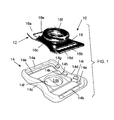
- FIG. 1 is an exploded perspective view of the buckle assembly of the invention before a metal part of the buckle is mated to a non-marring part of the assembly;
- FIG. 2 is an inside perspective view of the assembly, ready to receive a chin strap and be snapped to a mating snap member fixed a sports helmet;
- FIG. 3 is an outside perspective view of the buckle assembly
- FIG. 4 is an inside perspective view of the non-marring part of an alternate embodiment of the buckle assembly of the invention.
- FIG. 5 is an inside perspective view of the non-marring part of a further embodiment of the buckle assembly of the invention.
- FIG. 6 is an inside perspective view of the non-marring part of a still further embodiment of the buckle assembly of the invention.
- FIG. 7 is an inside perspective view of the non-marring part of another alternate embodiment of the buckle assembly of the invention.
- FIG. 8 is an outside perspective view of the metal part of the buckle assembly before it is connected to the non-marring part;
- FIG. 9 is an inside perspective view of the non-marring part of another alternate embodiment of the buckle assembly of the invention.
- FIG. 10 is an outside exploded perspective view of a buckle assembly of the embodiment of FIG. 9 , with its metal part also shown;
- FIG. 11 is an exploded view of a further embodiment of the invention.
- FIG. 12 is a sectional view of the embodiment of FIG. 11 .
- FIG. 1 illustrates a buckle assembly 10 for holding a chin strap (not shown) to a sports helmet (not shown).
- the buckle assembly comprises a metal part 12 securely connected to a non-marring part 14 .
- the metal part can be made of any suitably strong metal such as, but not limited to, stainless steel or aluminum.
- the non-marring part can be made of any suitably strong synthetic material such as, but not limited to, polycarbonate or ABS (Acrylonitrile Butadiene Styrene).
- the non-marring part may also be coated with a layer of polytetrafluoroethylene (PTFE), for example, as sold under the trademark TEFLON by DuPont Co.
- PTFE polytetrafluoroethylene
- the non-marring or protective part 14 forms a protective buckle sleeve and can be made of any non-marring material or material combination that is less likely to scratch a helmet shell or catch on clothing or injure a player.
- Non-limiting examples include: graphite, ceramic, any strong plastic or plastic coated structure such as PTFE coated metal, or a copolymer of ethylene and methacrylic acid that is available from Dupont under the trademark SURLYN, or glass-filled nylon.
- the metal part 12 comprises a metal plate 16 having an outer perimeter with opposite end portions 16 a and 16 b , and a center portion 16 c between the end portions.
- the center portion 16 c is advantageously narrower than the end portions 16 a and 16 b for a compact buckle profile.
- a slots 16 d and 16 e extend side-to-side in each end portion.
- a snap member 16 f such as but not limited to a female snap member, is fixed to the center portion 16 c , for example, by a rivet 16 g shown in FIG. 8 , that extends through aligned holes in the center portion 16 c and in the snap member 16 f .
- the enlarged head of the rivet 16 g is visible in FIG. 8 , while the opposite end of the rivet is flared in the usual manner inside the snap member, for securing the snap member to the plate 16 , the flared end being partly visible on FIG. 2 .
- the non-marring part 14 comprises a tray made of polycarbonate or other strong plastics material.
- the tray has two end walls 14 a and 14 b , and two side walls 14 c and 14 d that are connected between the end walls.
- the end and side walls together defining an inner perimeter corresponding in shape and size to the outer perimeter of the metal plate 16 , and closely receives the metal plate within the tray.
- a shelve 14 e and 14 e extend side-to-side on an inner surface of each end wall, and each extends partly onto the inner surfaces of the adjacent side walls 14 c and 14 d as well.
- Three wedge-shaped locking tabs 14 g , 14 h and 14 i are molded into the inner surface of each side wall 14 c and 14 d.
- each wedge-shaped locking tab has an entry surface 141 that is inclined with respect to the inner surface of the side wall to which the locking tab is connected, and a locking surface 14 m that is substantially perpendicular to the inner surface of the side wall to which the locking tab is connected.
- This operation can be expedited by first wedging the opposite side edge of plate 16 , under the locking tabs on the opposite side wall 14 c , so that the other plate edge need pass only one set of tabs 14 g , 14 h and 14 i on the opposite side wall.
- the non-marring part 14 also includes one intermediate portion 14 n that connected to and between the inside surfaces of the side walls.
- this intermediate portion 14 n acts like a bridge between the side walls 14 c and 14 d .
- there are two intermediate portions 14 n each connected to one of the side walls.
- each slot 16 d and 16 e has one side with plural teeth 16 h and 16 i , each side with plural teeth being at the same end of the metal part.
- each end walls 14 a and 14 b is lower than each side walls 14 c and 14 d to the extend that the upper surface of each end wall as shown in FIG. 2 , is coplanar with the upper surface of the metal plate 16 at each end of the buckle assembly. This allows the chin strap to be easily passed through the slots 16 d and 16 e until the strap is pulled taught and is engaged by the teeth 16 h and 16 j which thereafter prevents any further relative motion between the buckle assembly and the strap.
- one intermediate portion 14 n when one intermediate portion 14 n is used, is forms a bridge connected between the side walls 14 c and 14 d .
- the one intermediate portion 14 n includes a recess 14 j for receiving the enlarged end of the rivet 16 g that projected above the surface of the plate 16 .
- the bridge 14 n has an end-to-end width that is about 12 to 45 percent of the total end-to-end width of the non-marring part 14 . As shown FIG.
- this range may be about 40 to 45 percent of the total end-to-end width of the non-marring part 14 if the rivet head is to be fully covered, or, as shown in FIG. 5 , this range may be about 12 to 20 percent of the total end-to-end width of the non-marring part 14 if the rivet head is to be partly covered.
- the intermediate portion 14 n may comprise separate ledges 14 n 1 and 14 n 2 on the inner surfaces of the respective side walls 14 c and 14 d .
- the ledges 14 n 1 and 14 n 2 are rectangular.
- they are concave and shaped to receive respective parts of the rivet 16 g .
- the intermediate portion ledges 14 n 1 , 14 n 2 are convex.
- the one intermediate portion 14 n or two intermediate portion ledges 14 n 1 and 14 n 2 also include a slot or opening 14 k adjacent each side wall 14 d under the adjacent locking tab 14 h with its locking surface 14 m spaced over the opening.
- This opening is about the same width as the width of the locking surface 14 m the was found to be necessary to properly mold the locking tab 14 h accurately to shape and was only discovered as part of the invention development process.
- FIGS. 9 and 10 illustrate a still further embodiment of the buckle assembly of the invention with small two intermediate ledge portions 14 n 1 and 14 n 2 so that the non-marring part 14 is in the form of a buckle sleeve around the metal plate of the metal part 12 .
- the non-marring part 14 comprises a tray made of polycarbonate or other strong plastics material.
- the tray has two end walls 14 a and 14 b , and two side walls 14 c and 14 d that are connected between the end walls and a bridge 14 n connected between the side walls 14 c , 14 d .
- the end and side walls together defining an inner perimeter corresponding in shape and size to the outer perimeter of the metal plate of the metal part 12 , and closely receives the metal plate within the tray.
- a single continuous rectangular shelf extends around the inside of the part 14 and a flexible strap 20 , such as the chin strap of a football helmet, extends through the aligned slots of the parts 12 and 14 to keep the parts together with no other locking of the parts to each other, other than the plate of the metal part being nested in the perimeter and on the shelf of the non-marring part.
- the strap 20 lies in a recess defined by the bridge 14 n which is recessed lower than the outer surfaces of the side walls 14 c , 14 d by about the thickness of the strap.
Abstract
Description
Claims (23)
Priority Applications (1)
| Application Number | Priority Date | Filing Date | Title |
|---|---|---|---|
| US14/790,508 US9486028B1 (en) | 2015-07-02 | 2015-07-02 | Chin strap buckle assembly for sports helmet |
Applications Claiming Priority (1)
| Application Number | Priority Date | Filing Date | Title |
|---|---|---|---|
| US14/790,508 US9486028B1 (en) | 2015-07-02 | 2015-07-02 | Chin strap buckle assembly for sports helmet |
Publications (1)
| Publication Number | Publication Date |
|---|---|
| US9486028B1 true US9486028B1 (en) | 2016-11-08 |
Family
ID=57210823
Family Applications (1)
| Application Number | Title | Priority Date | Filing Date |
|---|---|---|---|
| US14/790,508 Active 2035-07-29 US9486028B1 (en) | 2015-07-02 | 2015-07-02 | Chin strap buckle assembly for sports helmet |
Country Status (1)
| Country | Link |
|---|---|
| US (1) | US9486028B1 (en) |
Cited By (4)
| Publication number | Priority date | Publication date | Assignee | Title |
|---|---|---|---|---|
| USD877656S1 (en) * | 2018-10-04 | 2020-03-10 | Duraflex Hong Kong Limited | Buckle |
| US10869518B1 (en) * | 2020-05-05 | 2020-12-22 | Lionhead Helmet Intellectual Properties, Lp | Chin strap assembly for a protective helmet |
| USD948376S1 (en) * | 2020-04-17 | 2022-04-12 | Shanjun Liu | Slack |
| USD951081S1 (en) * | 2020-02-05 | 2022-05-10 | Sae Han Byul Cho | Strap length adjuster |
Citations (19)
| Publication number | Priority date | Publication date | Assignee | Title |
|---|---|---|---|---|
| US1712976A (en) * | 1924-03-05 | 1929-05-14 | Mishawaka Rubber & Woolen Mfg | Fastener |
| US3237257A (en) * | 1964-03-26 | 1966-03-01 | United Carr Inc | Plastic buckle |
| US3977839A (en) * | 1973-11-21 | 1976-08-31 | The Empire Plating Company | Coated metal article and method of coating |
| US5259096A (en) * | 1992-09-22 | 1993-11-09 | Athletic Specialties, Inc. | Slide socket and method for making same |
| US20020148081A1 (en) * | 2001-02-07 | 2002-10-17 | Thad Ide | Buckle |
| US6481066B1 (en) * | 2001-02-07 | 2002-11-19 | Southern Impact Research Center, Llc | Buckle |
| US6532632B1 (en) * | 2001-02-07 | 2003-03-18 | P. David Halstead | Buckle |
| US20060242803A1 (en) * | 2005-04-27 | 2006-11-02 | Hos Development Corporation | Buckle |
| US7246384B2 (en) * | 2005-01-07 | 2007-07-24 | William George Bentz | Headgear and chin strap with magnetic fastener |
| US20070193006A1 (en) * | 2006-02-17 | 2007-08-23 | Katsushi Kitano | One-way safety locking buckles |
| USD628515S1 (en) * | 2009-10-22 | 2010-12-07 | Paul Schiebl | Injection molded snap |
| US8056151B2 (en) * | 2008-10-15 | 2011-11-15 | Riddell, Inc. | Buckle for a chin strap assembly for a sports helmet |
| US20140068843A1 (en) * | 2012-09-11 | 2014-03-13 | James D. Wegener | Helmet |
| US8813317B2 (en) * | 2010-11-09 | 2014-08-26 | Home Team Sports, LLC. | Strap latching device |
| USD713759S1 (en) * | 2008-01-11 | 2014-09-23 | Resmed Limited | Buckle |
| USD714683S1 (en) * | 2014-02-20 | 2014-10-07 | GSG Fasteners, LLC | Buckle for helmet strap |
| US9144270B2 (en) * | 2013-03-15 | 2015-09-29 | Home Team Sports, Llc | Strap latching device |
| USD750530S1 (en) * | 2015-04-30 | 2016-03-01 | Kranos Ip Corporation | Chin strap buckle sleeve |
| USD760067S1 (en) * | 2013-10-17 | 2016-06-28 | Hellermanntyton Corporation | Mount |
-
2015
- 2015-07-02 US US14/790,508 patent/US9486028B1/en active Active
Patent Citations (22)
| Publication number | Priority date | Publication date | Assignee | Title |
|---|---|---|---|---|
| US1712976A (en) * | 1924-03-05 | 1929-05-14 | Mishawaka Rubber & Woolen Mfg | Fastener |
| US3237257A (en) * | 1964-03-26 | 1966-03-01 | United Carr Inc | Plastic buckle |
| US3977839A (en) * | 1973-11-21 | 1976-08-31 | The Empire Plating Company | Coated metal article and method of coating |
| US5259096A (en) * | 1992-09-22 | 1993-11-09 | Athletic Specialties, Inc. | Slide socket and method for making same |
| US20020148081A1 (en) * | 2001-02-07 | 2002-10-17 | Thad Ide | Buckle |
| US6481066B1 (en) * | 2001-02-07 | 2002-11-19 | Southern Impact Research Center, Llc | Buckle |
| US6497012B2 (en) * | 2001-02-07 | 2002-12-24 | Southern Impact Research Center, Llc | Buckle |
| US6532632B1 (en) * | 2001-02-07 | 2003-03-18 | P. David Halstead | Buckle |
| US7246384B2 (en) * | 2005-01-07 | 2007-07-24 | William George Bentz | Headgear and chin strap with magnetic fastener |
| US7475453B2 (en) * | 2005-04-27 | 2009-01-13 | Melas, Inc. | Buckle |
| US20060242803A1 (en) * | 2005-04-27 | 2006-11-02 | Hos Development Corporation | Buckle |
| US20070193006A1 (en) * | 2006-02-17 | 2007-08-23 | Katsushi Kitano | One-way safety locking buckles |
| USD713759S1 (en) * | 2008-01-11 | 2014-09-23 | Resmed Limited | Buckle |
| US8056151B2 (en) * | 2008-10-15 | 2011-11-15 | Riddell, Inc. | Buckle for a chin strap assembly for a sports helmet |
| USD628515S1 (en) * | 2009-10-22 | 2010-12-07 | Paul Schiebl | Injection molded snap |
| US8813317B2 (en) * | 2010-11-09 | 2014-08-26 | Home Team Sports, LLC. | Strap latching device |
| US20140068843A1 (en) * | 2012-09-11 | 2014-03-13 | James D. Wegener | Helmet |
| US9125446B2 (en) * | 2012-09-11 | 2015-09-08 | James D. Wegener | Helmet with a chin strap buckle system |
| US9144270B2 (en) * | 2013-03-15 | 2015-09-29 | Home Team Sports, Llc | Strap latching device |
| USD760067S1 (en) * | 2013-10-17 | 2016-06-28 | Hellermanntyton Corporation | Mount |
| USD714683S1 (en) * | 2014-02-20 | 2014-10-07 | GSG Fasteners, LLC | Buckle for helmet strap |
| USD750530S1 (en) * | 2015-04-30 | 2016-03-01 | Kranos Ip Corporation | Chin strap buckle sleeve |
Cited By (4)
| Publication number | Priority date | Publication date | Assignee | Title |
|---|---|---|---|---|
| USD877656S1 (en) * | 2018-10-04 | 2020-03-10 | Duraflex Hong Kong Limited | Buckle |
| USD951081S1 (en) * | 2020-02-05 | 2022-05-10 | Sae Han Byul Cho | Strap length adjuster |
| USD948376S1 (en) * | 2020-04-17 | 2022-04-12 | Shanjun Liu | Slack |
| US10869518B1 (en) * | 2020-05-05 | 2020-12-22 | Lionhead Helmet Intellectual Properties, Lp | Chin strap assembly for a protective helmet |
Similar Documents
| Publication | Publication Date | Title |
|---|---|---|
| US9486028B1 (en) | Chin strap buckle assembly for sports helmet | |
| US7634820B2 (en) | Adjustment mechanism for a helmet | |
| US20160143785A1 (en) | Protective eye mask, particularly for skiing | |
| US10244831B2 (en) | Two-part watch strap | |
| US9372384B2 (en) | Camera quick attachment and release mechanism | |
| US8402569B2 (en) | Swim goggles | |
| US8056151B2 (en) | Buckle for a chin strap assembly for a sports helmet | |
| US11266197B2 (en) | Mounting assembly for a face shield with an enhanced base | |
| US10188175B2 (en) | Buckle assembly and respiratory mask including the same | |
| US9770074B2 (en) | Cap structure having a plurality of breach hole features and zipper head assembly structure using the same | |
| US20130181021A1 (en) | Fully integrated molded firearm holster retention system | |
| US20180084859A1 (en) | Helmet assembly and helmet fastening system | |
| US9560900B2 (en) | Adjustable watch strap | |
| US20160192726A1 (en) | Adjustment device of the position of a first part with respect to a second part and protective helmet comprising one such device | |
| WO2021143704A1 (en) | Buckle | |
| US20170035614A1 (en) | Fixed structure for the constricting band of snow goggles | |
| US20090113607A1 (en) | Connection of goggle and mask | |
| US5327619A (en) | Plunger releasable latch | |
| CA2934392C (en) | Mechanical connector and helmet assembly including the same | |
| US8857019B1 (en) | Service belt buckle | |
| US6497012B2 (en) | Buckle | |
| US20180228271A1 (en) | Back frame | |
| US20210153588A1 (en) | Anti-off device, and protective hat having the same | |
| US10485306B1 (en) | Quick release system for body armor | |
| US20070234526A1 (en) | Clipping piece structure for goggles |
Legal Events
| Date | Code | Title | Description |
|---|---|---|---|
| AS | Assignment |
Owner name: KRANOS IP CORPORATION, ILLINOIS Free format text: ASSIGNMENT OF ASSIGNORS INTEREST;ASSIGNORS:VANHOUTIN, LOUIS ANTHONY;HALPIN, NORMAN M.;WARMOUTH, CORTNEY;AND OTHERS;SIGNING DATES FROM 20150417 TO 20150707;REEL/FRAME:036224/0503 |
|
| AS | Assignment |
Owner name: GARRISON LOAN AGENCY SERVICES LLC, NEW YORK Free format text: SECURITY AGREEMENT SUPPLEMENT;ASSIGNORS:KRANOS ACQUISITION CORPORATION;KRANOS CORPORATION;KRANOS RE CORPORATION;AND OTHERS;REEL/FRAME:038891/0548 Effective date: 20160526 |
|
| AS | Assignment |
Owner name: WELLS FARGO CAPITAL FINANCE, LLC, CALIFORNIA Free format text: PATENT SECURITY AGREEMENT SUPPLEMENT;ASSIGNORS:KRANOS ACQUISITION CORPORATION;KRANOS CORPORATION;KRANOS RE CORPORATION;AND OTHERS;REEL/FRAME:039053/0255 Effective date: 20160526 |
|
| STCF | Information on status: patent grant |
Free format text: PATENTED CASE |
|
| AS | Assignment |
Owner name: KRANOS ACQUISITION CORPORATION, ILLINOIS Free format text: RELEASE OF SECURITY INTERESTS IN PATENTS;ASSIGNOR:WELLS FARGO BANK, NATIONAL ASSOCIATION;REEL/FRAME:046090/0671 Effective date: 20180430 Owner name: KRANOS IP II CORPORATION, ILLINOIS Free format text: RELEASE OF SECURITY INTERESTS IN PATENTS;ASSIGNOR:WELLS FARGO BANK, NATIONAL ASSOCIATION;REEL/FRAME:046090/0671 Effective date: 20180430 Owner name: KRANOS IP III CORPORATION, ILLINOIS Free format text: RELEASE OF SECURITY INTERESTS IN PATENTS;ASSIGNOR:WELLS FARGO BANK, NATIONAL ASSOCIATION;REEL/FRAME:046090/0671 Effective date: 20180430 Owner name: KRANOS CORPORATION, ILLINOIS Free format text: RELEASE OF SECURITY INTERESTS IN PATENTS;ASSIGNOR:WELLS FARGO BANK, NATIONAL ASSOCIATION;REEL/FRAME:046090/0671 Effective date: 20180430 Owner name: KRANOS IP CORPORATION, ILLINOIS Free format text: RELEASE OF SECURITY INTERESTS IN PATENTS;ASSIGNOR:WELLS FARGO BANK, NATIONAL ASSOCIATION;REEL/FRAME:046090/0671 Effective date: 20180430 Owner name: KRANOS RE CORPORATION, ILLINOIS Free format text: RELEASE OF SECURITY INTERESTS IN PATENTS;ASSIGNOR:WELLS FARGO BANK, NATIONAL ASSOCIATION;REEL/FRAME:046090/0671 Effective date: 20180430 |
|
| AS | Assignment |
Owner name: ISRAEL DISCOUNT BANK OF NEW YORK, NEW YORK Free format text: SECURITY AGREEMENT;ASSIGNORS:KRANOS IP CORPORATION;KRANOS IP II CORPORATION;KRANOS IP III CORPORATION;AND OTHERS;REEL/FRAME:050610/0004 Effective date: 20190930 |
|
| AS | Assignment |
Owner name: INNOVATUS FLAGSHIP FUND I, LP, ADMINISTRATIVE AGEN Free format text: SECURITY INTEREST;ASSIGNOR:KRANOS IP CORPORATION;REEL/FRAME:050632/0398 Effective date: 20191001 Owner name: INNOVATUS FLAGSHIP FUND I, LP, ADMINISTRATIVE AGENT, NEW YORK Free format text: SECURITY INTEREST;ASSIGNOR:KRANOS IP CORPORATION;REEL/FRAME:050632/0398 Effective date: 20191001 |
|
| MAFP | Maintenance fee payment |
Free format text: PAYMENT OF MAINTENANCE FEE, 4TH YR, SMALL ENTITY (ORIGINAL EVENT CODE: M2551); ENTITY STATUS OF PATENT OWNER: SMALL ENTITY Year of fee payment: 4 |
|
| AS | Assignment |
Owner name: SCHUTT SPORTS IP, LLC, ILLINOIS Free format text: ASSIGNMENT OF ASSIGNORS INTEREST;ASSIGNOR:KRANOS IP CORPORATION;REEL/FRAME:054635/0265 Effective date: 20201204 |
|
| AS | Assignment |
Owner name: SIENA LENDING GROUP LLC, CONNECTICUT Free format text: SECURITY AGREEMENT;ASSIGNORS:SCHUTT SPORTS, LLC;SCHUTT SPORTS RE, LLC;SCHUTT SPORTS IP, LLC;AND OTHERS;REEL/FRAME:056648/0771 Effective date: 20210618 |
|
| AS | Assignment |
Owner name: SCHUTT SPORTS IP, LLC, ILLINOIS Free format text: RELEASE BY SECURED PARTY;ASSIGNOR:ISRAEL DISCOUNT BANK OF NEW YORK;REEL/FRAME:056815/0954 Effective date: 20210618 |
|
| AS | Assignment |
Owner name: INNOVATUS FLAGSHIP FUND I, LP, NEW YORK Free format text: SECURITY INTEREST;ASSIGNORS:CERTOR SPORTS, LLC;VICIS ACQUISITIONCO, LLC;VICIS, LLC;AND OTHERS;REEL/FRAME:056893/0877 Effective date: 20210618 |
|
| AS | Assignment |
Owner name: SIENA LENDING GROUP LLC, CONNECTICUT Free format text: SECURITY INTEREST;ASSIGNORS:SCHUTT SPORTS IP, LLC;VICIS IP, LLC;REEL/FRAME:060692/0032 Effective date: 20220713 |
|
| FEPP | Fee payment procedure |
Free format text: ENTITY STATUS SET TO UNDISCOUNTED (ORIGINAL EVENT CODE: BIG.); ENTITY STATUS OF PATENT OWNER: LARGE ENTITY |