US9488273B2 - Neutral locking system, tool and method for a vehicle - Google Patents
Neutral locking system, tool and method for a vehicle Download PDFInfo
- Publication number
- US9488273B2 US9488273B2 US14/074,674 US201314074674A US9488273B2 US 9488273 B2 US9488273 B2 US 9488273B2 US 201314074674 A US201314074674 A US 201314074674A US 9488273 B2 US9488273 B2 US 9488273B2
- Authority
- US
- United States
- Prior art keywords
- rotatable element
- rotatable
- release shaft
- park release
- fixture
- Prior art date
- Legal status (The legal status is an assumption and is not a legal conclusion. Google has not performed a legal analysis and makes no representation as to the accuracy of the status listed.)
- Active, expires
Links
Images


Classifications
-
- F—MECHANICAL ENGINEERING; LIGHTING; HEATING; WEAPONS; BLASTING
- F16—ENGINEERING ELEMENTS AND UNITS; GENERAL MEASURES FOR PRODUCING AND MAINTAINING EFFECTIVE FUNCTIONING OF MACHINES OR INSTALLATIONS; THERMAL INSULATION IN GENERAL
- F16H—GEARING
- F16H63/00—Control outputs from the control unit to change-speed- or reversing-gearings for conveying rotary motion or to other devices than the final output mechanism
- F16H63/02—Final output mechanisms therefor; Actuating means for the final output mechanisms
- F16H63/30—Constructional features of the final output mechanisms
- F16H63/34—Locking or disabling mechanisms
- F16H63/3416—Parking lock mechanisms or brakes in the transmission
- F16H63/3491—Emergency release or engagement of parking locks or brakes
-
- Y—GENERAL TAGGING OF NEW TECHNOLOGICAL DEVELOPMENTS; GENERAL TAGGING OF CROSS-SECTIONAL TECHNOLOGIES SPANNING OVER SEVERAL SECTIONS OF THE IPC; TECHNICAL SUBJECTS COVERED BY FORMER USPC CROSS-REFERENCE ART COLLECTIONS [XRACs] AND DIGESTS
- Y10—TECHNICAL SUBJECTS COVERED BY FORMER USPC
- Y10T—TECHNICAL SUBJECTS COVERED BY FORMER US CLASSIFICATION
- Y10T74/00—Machine element or mechanism
- Y10T74/20—Control lever and linkage systems
- Y10T74/20012—Multiple controlled elements
- Y10T74/20018—Transmission control
- Y10T74/20085—Restriction of shift, gear selection, or gear engagement
- Y10T74/20104—Shift element interlock
Definitions
- Vehicle transmissions sometimes must be put into a neutral state in order for various service operations to be performed on the vehicle.
- this can be as simple as moving the manual shift lever to the neutral position.
- a locking mechanism is provided for engaging the manual shift lever and holding or locking the shift lever in the neutral position so as to prevent the shift lever from inadvertently moving out of the neutral position.
- a particular method and/or arrangement may be needed for the particular transmission that is to be placed into the neutral state.
- a neutral locking system for a vehicle includes a park release shaft operatively connected to a transmission of the vehicle such that rotation of the park release shaft in a first rotatable direction places the transmission in a neutral state.
- the park release shaft is located adjacent an aperture of a transmission case housing the transmission.
- the neutral locking system further includes a neutral locking tool for rotating the park release shaft.
- the neutral locking tool includes a fixture element for positioning over the aperture of the transmission case and a rotatable element rotatably received within the fixture element and having one end configured to nonrotatably and removably couple to the park release shaft such that rotation of the rotatable element within the fixture element rotates the park release shaft.
- a neutral locking method for rotating a transmission park release shaft of a vehicle to place a transmission of the vehicle in a neutral state.
- a neutral locking tool is provided that has a fixture element for positioning over an aperture of a transmission case of the transmission and a rotatable element rotatably received within the fixture element.
- One end of the rotatable element is nonrotatably and removably coupled to the park release shaft such that rotation of the rotatable element within the fixture element rotates the park release shaft.
- a neutral locking tool for a vehicle includes a fixture element and a rotatable element.
- the fixture element is for positioning over an aperture of a transmission case adjacent which a park release shaft is located that is operatively connected to a vehicle transmission for placing the transmission in a neutral state upon rotation thereof.
- the rotatable element is rotatably received within the fixture element and has one end configured to nonrotatably and removably couple with the park release shaft such that rotation of the rotatable element within the fixture element rotates the park release shaft.
- FIG. 1 is a perspective view of a neutral locking tool according to one exemplary embodiment.
- FIG. 2 is an exploded perspective view of the neutral locking tool of FIG. 1 .
- FIG. 3 is a side elevation view, partially in cross-section, of the neutral locking tool of FIG. 1 .
- FIG. 4 is a top plan view of the neutral locking tool of FIG. 1 .
- FIG. 5 is an underside plan view of the neutral locking tool of FIG. 1 .
- FIG. 6 is a partial perspective view of a neutral locking system including park release shaft of a vehicle transmission and the neutral locking tool of FIGS. 1-5 for removably coupling and rotating the park release shaft.
- FIG. 7 is a partial perspective view of a neutral locking system showing the neutral locking tool and the park release shaft disposed within an engine compartment, and further showing a ratchet tool removably secured to the neutral locking tool for rotating the park release shaft via the neutral locking tool.
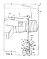
- FIG. 8 is another partial perspective view, similar to FIG. 7 , but showing the ratchet tool rotated to rotate a rotatable element of the neutral locking tool, which thereby rotates the park release shaft to place the transmission in a neutral state.
- FIG. 9 is a cross-section view taken along the line 9 - 9 of FIG. 7 .
- FIG. 10 is a cross-section view taken along the line 10 - 10 of FIG. 8 .
- FIG. 12 is a perspective view similar to FIG. 11 , but showing the transmission in the neutral state.
- FIG. 13 is a process flow diagram illustrating a neutral locking method for a transmission of a vehicle.
- FIGS. 1-6 illustrate a neutral locking system 10 for a vehicle 12 that includes a neutral locking tool 14 for rotating a park release shaft 16 of the vehicle 12 .
- the park release shaft 16 is operatively coupled or connected to a transmission 18 of the vehicle 12 such that rotation of the park release shaft 16 places the transmission 18 in a neutral state.
- the transmission 18 in such a neutral state can allow for various service operations to be performed on the vehicle 12 .
- a polygonal-shaped portion or protuberance 24 in the shape of a block member is positioned on, or extends or protrudes upward from, the transmission case 20 , and more specifically on/from a top wall or upper side 20 a of the transmission case 20 .
- the aperture 22 is specifically defined in or by the protuberance 24 with an open end 22 a of the aperture 22 defined in an upper surface 24 a of the protuberance 24 .
- the park release shaft 16 is shown inside the transmission case 20 .
- a plate member 26 is fixably secured to the park release shaft 16 inside the transmission case 20 such that rotation of the park release shaft 16 causes rotation of the plate member 26 .
- the plate member 26 can be specifically arranged such that a vertical axis of the park release shaft 16 defined by a longitudinal or axial extent of the park release shaft 16 is orthogonally oriented relative to a plane in which the plate member 26 resides.
- the plate member 26 has an arm portion 26 a to which a proximal end 28 a of a park release rod 28 is connected.
- a distal end 28 b of the park release rod 28 normally urges and/or maintains a parking pawl 30 in an engaged position ( FIG. 11 ) against the biasing of a parking pawl spring 32 wherein a tooth 30 a of the parking pawl 30 meshes with gear teeth 34 a of a parking gear 34 of the transmission 18 .
- This position can correspond to the transmission 18 being in a park state (and/or can correspond to an engine of the vehicle 12 being off) and functions to limit vehicle movement.
- the distal end 28 b includes an engaging member 36 slidably disposed on the park release rod 28 for engaging the parking pawl 30 which, in turn, causes the tooth 30 a to engage and/or mesh with the parking gear teeth 34 a.
- the engaging member 36 is urged away from the proximal end 28 a by a coil spring 38 arranged between the engaging member 36 and a washer member 40 arranged on the park release rod 28 between the proximal and distal ends 28 a, 28 b.
- a spring 42 can be connected to an arm portion 26 b of the plate member 26 for biasing the plate member 26 and thereby the park release shaft 16 in a second rotatable direction (a rotatable direction opposite the first rotatable direction).
- the plate member 26 When the park release shaft 16 is rotated in the first rotatable direction, as shown in FIG. 12 , the plate member 26 likewise rotates and causes the park release rod 28 to move away from the parking pawl 30 . This in turn causes the engaging member 36 to pull away from the parking pawl 30 thereby allowing the parking pawl spring 32 to rotate the parking pawl 30 out of meshing engagement with the parking gear 34 . This disengages the parking gear 34 . Accordingly, the parking gear 34 is then free to rotate and the transmission is placed in a neutral state.
- the neutral locking tool 14 of the illustrated embodiment includes a fixture element 50 for positioning over the aperture 22 of the transmission case 20 and a rotatable element 52 rotatably received within the fixture element 50 .
- the rotatable element 52 has one end (i.e., lower end 52 a ) configured to nonrotatably and removably couple to the park release shaft 16 such that rotation of the rotatable element 52 within the fixture element 50 rotates the park release shaft 16 .
- the rotatable element 52 is rotatably movable within the fixture element 50 between a first rotatable element position corresponding to the park release shaft being a non-neutral position and a second rotatable element position corresponding to the park release shaft being in a neutral position.
- the neutral locking tool can include one or both of a rotation limiting feature and a rotation locking feature.
- the fixture element 50 and the rotatable element 52 can be configured such that cooperative engagement between the rotatable element 52 and the fixture element 50 can limit a degree of rotation of the rotatable element 52 relative to the fixture element 50 .
- the fixture element 50 and the rotatable element 52 can be configured such that cooperative engagement therebetween can limit axial movement of the elements 50 , 52 relative to one another. More particularly, in the illustrated embodiment, the cooperative engagement between the rotatable element 52 and the fixture element 50 limits rotation of the rotatable element 52 between the first rotatable element position (shown in FIGS.
- one of the fixture element 50 and the rotatable element 52 can define a circumferentially elongated slot (e.g., circumferentially elongated slot 54 ) and the other of the fixture element 50 and the rotatable element 52 can include a fixedly secured pin (e.g., fixedly secured pin 56 ), wherein the pin is received in the circumferentially elongated slot to limit rotation of the rotatable element 52 relative to the fixture element 50 .
- the fixture element 50 can define the circumferentially elongated slot 54 in a cylindrical sleeve portion 58 and the rotatable element 52 , which can be cylinder-shaped and received within the cylindrical sleeve portion 58 , can include the fixedly secured pin 56 .
- the rotatable element 52 of the illustrated embodiment is received in the cylindrical sleeve portion 58 with a radial extent of the rotation of the rotatable element 52 relative to the fixture element 50 limited by the circumferentially elongated slot 54 . That is, rotation of the rotatable element 52 causes rotation of the fixedly secured pin 56 within the circumferentially elongated slot 54 .
- Elongated ends 54 a, 54 b of the slot 54 define limit stops for the pin 56 and thus for rotation of the rotatable element 52 within the fixture element 50 .
- the pin 56 in contact with the end 54 a of the slot 54 can correspond to the rotatable element 52 being in the first rotatable element position and the pin 56 in contact with the end 54 b of the slot 54 can correspond to the rotatable element 54 being in the second rotatable element position.
- the pin 56 in the slot 54 also fixes the axial position of the rotatable element 52 and the fixture element 50 relative to one another (i.e., the elements 50 , 52 cannot move axially relative to one another).
- the park release shaft 16 is a stub shaft that protrudes only slightly from the transmission case 20 , and particularly from the protuberance 24 of the transmission case 20 .
- the park release shaft 16 can be disposed such that its upper end is vertically spaced apart from an upper end of an engine compartment 60 .
- the park release shaft 16 of the illustrated embodiment has a keyed configuration that can be cooperatively engaged by the lower end 52 a of the rotatable element 52 for rotation of the park release shaft 16 .
- the mating slot 62 can be formed by a diametrically extending cross slot drilled through the rotatable element 52 .
- a counterbore portion 68 can be disposed below the mating slot 62 .
- the mating slot 62 is shown centrally located on the rotatable element 52 and likewise the keyed portion 16 a is centrally provided on the park release shaft 16 , it is to be understood and appreciated by those skilled in the art that other arrangements could be employed (e.g., the keyed portion 16 a and the mating slot 62 could be eccentrically located).
- the precise cooperative axial engagement between the rotatable element 52 and the park release shaft 16 can vary from what is shown in the illustrated embodiment as the cooperative engagement need only transfer rotation of the rotatable element 52 to rotation of the park release shaft 16 .
- the rotatable element 52 can additionally include a tool slot 64 adjacent an upper end 52 b thereof, which can be referred to as an upper axial end, for receipt of a rotating tool 66 configured to rotate the rotatable element 52 and thereby the park release shaft 16 .
- the rotating tool 66 can be a ratchet that includes an elongated engaging shaft 66 a to facilitate the lower end thereof reaching the tool slot 64 on the rotatable element 52 , which is disposed adjacent the park release shaft 16 , particularly in environments where the park release shaft 16 projects a minimal amount from the transmission case 20 (e.g., as shown in FIGS.
- the rotating tool 66 can include a handle 66 b for providing leveraged rotation or turning on the rotatable element 52 . This can assist in rotating the park release shaft 16 in the first rotatable direction since such rotation is against the urging of the park release shaft 16 in the second rotatable direction. While the rotating tool 66 is shown as a ratchet in the illustrated embodiment, it is to be appreciated that other rotating tools could be used (e.g., a T-handle, etc.).
- the neutral locking tool 14 can further include a plunger element 72 disposed on the fixture element 50 .
- the plunger element 72 can be radially movable between a retracted position (shown in FIG. 9 ) wherein relative rotation of the rotatable element 52 is allowed, at least within the extent permitted by the slot 54 , and a locking position (shown in FIG. 10 ) wherein the plunger element 72 inhibits relative rotation of the rotatable element 52 .
- a spring 74 can urge the plunger element 72 toward the locking position wherein the plunger element 72 inserts into the rotatable element 52 to limit rotation of the rotatable element 52 relative to the fixture element 50 .
- the rotatable element 52 includes an aperture 76 into which the plunger element 72 is received when the plunger element 72 is in the locking position and the rotatable element 52 is rotated to thereby rotate the park release shaft 16 and place the transmission in the neutral state.
- the plunger element 72 includes a flange portion 72 a and is axially disposed within a threaded member 78 .
- the spring 74 is axially interposed between the flange portion 72 a and one end 78 a of the threaded member 78 .
- the threaded member 78 is threadedly secured to a sleeve portion 80 protruding radially from the cylindrical sleeve portion 58 at the location of an aperture 82 defined in the cylindrical sleeve portion 58 .
- the plunger element 72 can include a ring member 84 for pulling the plunger element 72 radially outwardly toward the retracted position against the urging of the spring 74 when desired (e.g., when desired to remove the plunger element 72 from the aperture 76 of the rotatable element 52 ).
- the plunger element 72 engages the rotatable element 52 via the urging of the spring 74 but only about a circumferential surface of the rotatable element 52 .
- the aperture 76 is aligned with the aperture 82 and the spring 74 can forcibly move the plunger element 72 so that the plunger element 72 inserts into the aperture 76 of the rotatable element 52 to thereby lock the rotatable position of the rotatable element 52 relative to the fixture element 50 .
- the fixture element 50 can additionally have a lower end portion 86 configured to complementarily fit over and couple with the protuberance 24 to axially align the rotatable element 52 with the park release shaft 16 .
- the lower end portion 86 includes a main body 88 and plate members 90 , 92 secured to lateral sides of the main body 88 .
- the main body 88 can include a counterbore 94 shaped and sized to complementarily fit a lower end 58 a of the cylindrical sleeve portion 58 . These parts 58 , 88 can be welded together as shown in FIG. 1 .
- a throughole 96 can be defined through the main body 88 for partially receiving the rotatable element 52 , particularly the lower end 52 a thereof.
- Stepped sections 98 , 100 can be defined in an underside of the main body 88 for complementarily fitting over the protuberance 24 .
- the method can also include positioning the fixture element 50 over the aperture 22 of the transmission case 20 as indicated at 112 .
- Such positioning of the fixture element 50 can be as described hereinabove with respect to the lower end portion 86 of the fixture element 50 being positioned about the protuberance 24 of the transmission case 20 .
- the neutral locking tool 14 can be nonrotatably and removably coupled to the park release shaft 16 as indicated at 114 .
- the lower end 52 a of the rotatable element 52 can be axially coupled to the park release shaft 16 such that rotation of the rotatable element 52 within the fixture element 50 rotates the park release shaft 16 .
- the neutral locking tool 14 can be rotated to rotate the park release shaft 16 .
- the rotatable element 52 can be rotated within and relative to the fixture element 50 after nonrotatably and removably coupling the one end (i.e., the lower end 52 a ) of the rotatable element 52 to the park release shaft 16 to rotate the park release shaft 16 and place the transmission 18 in the neutral state.
- rotation of the rotatable element 52 relative to the fixture element 50 can be limited by receipt of the pin 56 fixably secured to one of the rotatable element 52 and the fixture element 50 (i.e., fixably secured to the fixture element 50 in the illustrated embodiment) within the circumferentially elongated slot 54 defined in the other of the rotatable element 50 and the fixture element 52 (i.e., defined in the fixture element 50 in the illustrated embodiment).
- the neutral locking tool 14 can be locked in position as described hereinabove with respect to the plunger element 72 .
- relative rotation between the rotatable element 52 and the fixture element 50 can be locked by radially inserting the plunger element 72 of the fixture element 50 into the radially defined aperture 76 in the rotatable element 52 .
- the plunger element 72 can be retracted against the urging of the spring 74 via the ring member 84 so as to unlock the rotatable element 52 and enable rotation of the neutral locking tool, and particularly the rotatable element 52 , back to the first rotatable element position.
Abstract
A neutral locking system and method for a vehicle includes a park release shaft and a neutral locking tool. The park release shaft is operatively connected to a transmission of the vehicle such that rotation of the park release shaft in a first rotatable direction places the transmission in a neutral state. The neutral locking includes a fixture element and a rotatable element rotatably received within the fixture element. The rotatable element has one end configured to nonrotatably and removably couple to the park release shaft such that rotation of the rotatable element within the fixture element rotates the park release shaft.
Description
Vehicle transmissions sometimes must be put into a neutral state in order for various service operations to be performed on the vehicle. In a manual transmission, this can be as simple as moving the manual shift lever to the neutral position. In one known manual transmission, a locking mechanism is provided for engaging the manual shift lever and holding or locking the shift lever in the neutral position so as to prevent the shift lever from inadvertently moving out of the neutral position. In automatic transmissions, a particular method and/or arrangement may be needed for the particular transmission that is to be placed into the neutral state.
According to one aspect, a neutral locking system for a vehicle includes a park release shaft operatively connected to a transmission of the vehicle such that rotation of the park release shaft in a first rotatable direction places the transmission in a neutral state. The park release shaft is located adjacent an aperture of a transmission case housing the transmission. The neutral locking system further includes a neutral locking tool for rotating the park release shaft. The neutral locking tool includes a fixture element for positioning over the aperture of the transmission case and a rotatable element rotatably received within the fixture element and having one end configured to nonrotatably and removably couple to the park release shaft such that rotation of the rotatable element within the fixture element rotates the park release shaft.
According to another aspect, a neutral locking method is provided for rotating a transmission park release shaft of a vehicle to place a transmission of the vehicle in a neutral state. In the method, a neutral locking tool is provided that has a fixture element for positioning over an aperture of a transmission case of the transmission and a rotatable element rotatably received within the fixture element. One end of the rotatable element is nonrotatably and removably coupled to the park release shaft such that rotation of the rotatable element within the fixture element rotates the park release shaft.
According to a further aspect, a neutral locking tool for a vehicle includes a fixture element and a rotatable element. The fixture element is for positioning over an aperture of a transmission case adjacent which a park release shaft is located that is operatively connected to a vehicle transmission for placing the transmission in a neutral state upon rotation thereof. The rotatable element is rotatably received within the fixture element and has one end configured to nonrotatably and removably couple with the park release shaft such that rotation of the rotatable element within the fixture element rotates the park release shaft.
Referring now to the drawings wherein the showings are for purposes of illustrating one or more exemplary embodiments and not for purposes of limiting the same, FIGS. 1-6 illustrate a neutral locking system 10 for a vehicle 12 that includes a neutral locking tool 14 for rotating a park release shaft 16 of the vehicle 12. As will be described in more detail below, the park release shaft 16 is operatively coupled or connected to a transmission 18 of the vehicle 12 such that rotation of the park release shaft 16 places the transmission 18 in a neutral state. The transmission 18 in such a neutral state can allow for various service operations to be performed on the vehicle 12.
More particularly, in the illustrated embodiment, a transmission case 20 houses the transmission 18 of the vehicle 12. As shown, the transmission case 20 can have an aperture 22 defined therein with the park release shaft 16 located adjacent the aperture 22 (e.g., extending through the aperture 22) such that the park release shaft 16 is accessible. The park release shaft 16 is operatively connected to the transmission 18 such that rotation of the park release shaft 16 in a first rotatable direction (i.e., counter clockwise in FIG. 6 ) places the transmission 18 into the neutral state. In the illustrated embodiment, a polygonal-shaped portion or protuberance 24 in the shape of a block member is positioned on, or extends or protrudes upward from, the transmission case 20, and more specifically on/from a top wall or upper side 20 a of the transmission case 20. The aperture 22 is specifically defined in or by the protuberance 24 with an open end 22 a of the aperture 22 defined in an upper surface 24 a of the protuberance 24.
With brief additional reference to FIGS. 11 and 12 , the park release shaft 16 is shown inside the transmission case 20. In the illustrated embodiment, a plate member 26 is fixably secured to the park release shaft 16 inside the transmission case 20 such that rotation of the park release shaft 16 causes rotation of the plate member 26. As shown, the plate member 26 can be specifically arranged such that a vertical axis of the park release shaft 16 defined by a longitudinal or axial extent of the park release shaft 16 is orthogonally oriented relative to a plane in which the plate member 26 resides. The plate member 26 has an arm portion 26 a to which a proximal end 28 a of a park release rod 28 is connected. A distal end 28 b of the park release rod 28 normally urges and/or maintains a parking pawl 30 in an engaged position (FIG. 11 ) against the biasing of a parking pawl spring 32 wherein a tooth 30 a of the parking pawl 30 meshes with gear teeth 34 a of a parking gear 34 of the transmission 18. This position can correspond to the transmission 18 being in a park state (and/or can correspond to an engine of the vehicle 12 being off) and functions to limit vehicle movement.
In the illustrated embodiment, the distal end 28 b includes an engaging member 36 slidably disposed on the park release rod 28 for engaging the parking pawl 30 which, in turn, causes the tooth 30 a to engage and/or mesh with the parking gear teeth 34 a. The engaging member 36 is urged away from the proximal end 28 a by a coil spring 38 arranged between the engaging member 36 and a washer member 40 arranged on the park release rod 28 between the proximal and distal ends 28 a, 28 b. The sliding arrangement of the engaging member 36 on the park release rod 28 allows for smoother cooperation between the park release rod 28 and the parking pawl 30, particularly when the tooth 30 a of the parking pawl 30 is not precisely aligned between two adjacent ones of the gear teeth 34 a of the parking gear 34. A spring 42 can be connected to an arm portion 26 b of the plate member 26 for biasing the plate member 26 and thereby the park release shaft 16 in a second rotatable direction (a rotatable direction opposite the first rotatable direction).
When the park release shaft 16 is rotated in the first rotatable direction, as shown in FIG. 12 , the plate member 26 likewise rotates and causes the park release rod 28 to move away from the parking pawl 30. This in turn causes the engaging member 36 to pull away from the parking pawl 30 thereby allowing the parking pawl spring 32 to rotate the parking pawl 30 out of meshing engagement with the parking gear 34. This disengages the parking gear 34. Accordingly, the parking gear 34 is then free to rotate and the transmission is placed in a neutral state.
Returning reference to FIGS. 1-6 , the neutral locking tool 14 of the illustrated embodiment includes a fixture element 50 for positioning over the aperture 22 of the transmission case 20 and a rotatable element 52 rotatably received within the fixture element 50. The rotatable element 52 has one end (i.e., lower end 52 a) configured to nonrotatably and removably couple to the park release shaft 16 such that rotation of the rotatable element 52 within the fixture element 50 rotates the park release shaft 16. The rotatable element 52 is rotatably movable within the fixture element 50 between a first rotatable element position corresponding to the park release shaft being a non-neutral position and a second rotatable element position corresponding to the park release shaft being in a neutral position. As will be describe in more detail below, the neutral locking tool can include one or both of a rotation limiting feature and a rotation locking feature.
As concerns the rotation limiting feature, the fixture element 50 and the rotatable element 52 can be configured such that cooperative engagement between the rotatable element 52 and the fixture element 50 can limit a degree of rotation of the rotatable element 52 relative to the fixture element 50. Also, the fixture element 50 and the rotatable element 52 can be configured such that cooperative engagement therebetween can limit axial movement of the elements 50, 52 relative to one another. More particularly, in the illustrated embodiment, the cooperative engagement between the rotatable element 52 and the fixture element 50 limits rotation of the rotatable element 52 between the first rotatable element position (shown in FIGS. 7 and 9 ) corresponding to the park release shaft 16 being in a normal, non-neutral position and a second rotatable element position (shown in FIGS. 8 and 10 ) corresponding to the park release shaft 16 being in a neutral position. In particular, one of the fixture element 50 and the rotatable element 52 can define a circumferentially elongated slot (e.g., circumferentially elongated slot 54) and the other of the fixture element 50 and the rotatable element 52 can include a fixedly secured pin (e.g., fixedly secured pin 56), wherein the pin is received in the circumferentially elongated slot to limit rotation of the rotatable element 52 relative to the fixture element 50.
More specifically, and particular to the illustrated embodiment, the fixture element 50 can define the circumferentially elongated slot 54 in a cylindrical sleeve portion 58 and the rotatable element 52, which can be cylinder-shaped and received within the cylindrical sleeve portion 58, can include the fixedly secured pin 56. As shown, the rotatable element 52 of the illustrated embodiment is received in the cylindrical sleeve portion 58 with a radial extent of the rotation of the rotatable element 52 relative to the fixture element 50 limited by the circumferentially elongated slot 54. That is, rotation of the rotatable element 52 causes rotation of the fixedly secured pin 56 within the circumferentially elongated slot 54. Elongated ends 54 a, 54 b of the slot 54 define limit stops for the pin 56 and thus for rotation of the rotatable element 52 within the fixture element 50. The pin 56 in contact with the end 54 a of the slot 54 can correspond to the rotatable element 52 being in the first rotatable element position and the pin 56 in contact with the end 54 b of the slot 54 can correspond to the rotatable element 54 being in the second rotatable element position. The pin 56 in the slot 54 also fixes the axial position of the rotatable element 52 and the fixture element 50 relative to one another (i.e., the elements 50, 52 cannot move axially relative to one another).
In the illustrated embodiment, and with further reference to FIGS. 7-10 , the park release shaft 16 is a stub shaft that protrudes only slightly from the transmission case 20, and particularly from the protuberance 24 of the transmission case 20. The park release shaft 16 can be disposed such that its upper end is vertically spaced apart from an upper end of an engine compartment 60. The park release shaft 16 of the illustrated embodiment has a keyed configuration that can be cooperatively engaged by the lower end 52 a of the rotatable element 52 for rotation of the park release shaft 16. In particular, the park release shaft 16 can have a keyed portion 16 a and the rotatable element 52 can include a mating slot 62 adjacent the lower end 52 a, which can also be referred to as a lower axial end, wherein the key portion 16 a is configured for cooperative axial receipt within the mating slot 62. Thus, the keyed portion 16 a of the park release shaft 16 can cooperatively fit within the mating slot 62 defined in the lower end 52 a of the rotatable element 52.
As shown, the mating slot 62 can be formed by a diametrically extending cross slot drilled through the rotatable element 52. Optionally, and as included in the illustrated embodiment, a counterbore portion 68 can be disposed below the mating slot 62. While in the illustrated embodiment, the mating slot 62 is shown centrally located on the rotatable element 52 and likewise the keyed portion 16 a is centrally provided on the park release shaft 16, it is to be understood and appreciated by those skilled in the art that other arrangements could be employed (e.g., the keyed portion 16 a and the mating slot 62 could be eccentrically located). Moreover, the precise cooperative axial engagement between the rotatable element 52 and the park release shaft 16 can vary from what is shown in the illustrated embodiment as the cooperative engagement need only transfer rotation of the rotatable element 52 to rotation of the park release shaft 16.
As shown, the rotatable element 52 can additionally include a tool slot 64 adjacent an upper end 52 b thereof, which can be referred to as an upper axial end, for receipt of a rotating tool 66 configured to rotate the rotatable element 52 and thereby the park release shaft 16. The rotating tool 66 can be a ratchet that includes an elongated engaging shaft 66 a to facilitate the lower end thereof reaching the tool slot 64 on the rotatable element 52, which is disposed adjacent the park release shaft 16, particularly in environments where the park release shaft 16 projects a minimal amount from the transmission case 20 (e.g., as shown in FIGS. 7 and 8 ) and/or where the park release shaft 16 is disposed deep or low into the engine compartment 60 of the vehicle 12 causing the park release shaft 16 to be relatively inaccessible. The rotating tool 66 can include a handle 66 b for providing leveraged rotation or turning on the rotatable element 52. This can assist in rotating the park release shaft 16 in the first rotatable direction since such rotation is against the urging of the park release shaft 16 in the second rotatable direction. While the rotating tool 66 is shown as a ratchet in the illustrated embodiment, it is to be appreciated that other rotating tools could be used (e.g., a T-handle, etc.).
As concerns the rotation locking feature, the neutral locking tool 14 can further include a plunger element 72 disposed on the fixture element 50. The plunger element 72 can be radially movable between a retracted position (shown in FIG. 9 ) wherein relative rotation of the rotatable element 52 is allowed, at least within the extent permitted by the slot 54, and a locking position (shown in FIG. 10 ) wherein the plunger element 72 inhibits relative rotation of the rotatable element 52. A spring 74 can urge the plunger element 72 toward the locking position wherein the plunger element 72 inserts into the rotatable element 52 to limit rotation of the rotatable element 52 relative to the fixture element 50. In the illustrated embodiment, the rotatable element 52 includes an aperture 76 into which the plunger element 72 is received when the plunger element 72 is in the locking position and the rotatable element 52 is rotated to thereby rotate the park release shaft 16 and place the transmission in the neutral state.
In the illustrated embodiment, the plunger element 72 includes a flange portion 72 a and is axially disposed within a threaded member 78. The spring 74 is axially interposed between the flange portion 72 a and one end 78 a of the threaded member 78. The threaded member 78 is threadedly secured to a sleeve portion 80 protruding radially from the cylindrical sleeve portion 58 at the location of an aperture 82 defined in the cylindrical sleeve portion 58. The plunger element 72 can include a ring member 84 for pulling the plunger element 72 radially outwardly toward the retracted position against the urging of the spring 74 when desired (e.g., when desired to remove the plunger element 72 from the aperture 76 of the rotatable element 52). When the rotatable element 52 is first removably and nonrotatably coupled to the park release shaft 16 wherein the rotatable element 52 is in the first rotatable element position shown in FIG. 9 , the plunger element 72 engages the rotatable element 52 via the urging of the spring 74 but only about a circumferential surface of the rotatable element 52. Once the rotatable element 52 is rotated (e.g., approximately 20 degrees), the aperture 76 is aligned with the aperture 82 and the spring 74 can forcibly move the plunger element 72 so that the plunger element 72 inserts into the aperture 76 of the rotatable element 52 to thereby lock the rotatable position of the rotatable element 52 relative to the fixture element 50.
The fixture element 50 can additionally have a lower end portion 86 configured to complementarily fit over and couple with the protuberance 24 to axially align the rotatable element 52 with the park release shaft 16. In the illustrated embodiment, the lower end portion 86 includes a main body 88 and plate members 90, 92 secured to lateral sides of the main body 88. The main body 88 can include a counterbore 94 shaped and sized to complementarily fit a lower end 58 a of the cylindrical sleeve portion 58. These parts 58, 88 can be welded together as shown in FIG. 1 . A throughole 96 can be defined through the main body 88 for partially receiving the rotatable element 52, particularly the lower end 52 a thereof. Stepped sections 98, 100 can be defined in an underside of the main body 88 for complementarily fitting over the protuberance 24.
With reference now to FIGS. 7-10 and 13 , a neutral locking method for rotating a transmission park release shaft of a vehicle to place a transmission of the vehicle in a neutral state will now be described. In particular, the method will be described in association with the neutral locking system 10 and neutral locking tool 14 described hereinabove though it is to be appreciated that the method could be used with other neutral locking systems and/or neutral locking tools. In one exemplary method, the neutral locking tool 14 is provided as indicated at 110, wherein the neutral locking tool includes the fixture element 50 for positioning over the aperture 22 of the transmission case 20 of the transmission 18 and also includes the rotatable element 52 rotatably received within the fixture element 50.
The method can also include positioning the fixture element 50 over the aperture 22 of the transmission case 20 as indicated at 112. Such positioning of the fixture element 50 can be as described hereinabove with respect to the lower end portion 86 of the fixture element 50 being positioned about the protuberance 24 of the transmission case 20. Also, as facilitated by such positioning, the neutral locking tool 14 can be nonrotatably and removably coupled to the park release shaft 16 as indicated at 114. For example, as shown in FIG. 7 , the lower end 52 a of the rotatable element 52 can be axially coupled to the park release shaft 16 such that rotation of the rotatable element 52 within the fixture element 50 rotates the park release shaft 16.
Once coupled, the neutral locking tool 14, and more particularly the rotatable element 52, can be rotated to rotate the park release shaft 16. In particular, the rotatable element 52 can be rotated within and relative to the fixture element 50 after nonrotatably and removably coupling the one end (i.e., the lower end 52 a) of the rotatable element 52 to the park release shaft 16 to rotate the park release shaft 16 and place the transmission 18 in the neutral state. As described hereinabove, rotation of the rotatable element 52 relative to the fixture element 50 can be limited by receipt of the pin 56 fixably secured to one of the rotatable element 52 and the fixture element 50 (i.e., fixably secured to the fixture element 50 in the illustrated embodiment) within the circumferentially elongated slot 54 defined in the other of the rotatable element 50 and the fixture element 52 (i.e., defined in the fixture element 50 in the illustrated embodiment).
Once in the neutral state, the neutral locking tool 14, and particularly the rotatable element 52 thereof, can be locked in position as described hereinabove with respect to the plunger element 72. In particular, relative rotation between the rotatable element 52 and the fixture element 50 can be locked by radially inserting the plunger element 72 of the fixture element 50 into the radially defined aperture 76 in the rotatable element 52. When desired, such as after completing service on the transmission 18, the plunger element 72 can be retracted against the urging of the spring 74 via the ring member 84 so as to unlock the rotatable element 52 and enable rotation of the neutral locking tool, and particularly the rotatable element 52, back to the first rotatable element position.
It will be appreciated that various of the above-disclosed and other features and functions, or alternatives or varieties thereof, may be desirably combined into many other different systems or applications. Also that various presently unforeseen or unanticipated alternatives, modifications, variations or improvements therein may be subsequently made by those skilled in the art which are also intended to be encompassed by the following claims.
Claims (18)
1. A neutral locking system for a vehicle, comprising:
a park release shaft operatively connected to a transmission of the vehicle such that rotation of the park release shaft in a first rotatable direction places the transmission in a neutral state, the park release shaft located adjacent an aperture of a transmission case housing the transmission; and
a neutral locking tool for rotating the park release shaft, the neutral locking tool including:
a fixture element for positioning over the aperture of the transmission case,
a plunger element disposed on the fixture element, the plunger element radially movable between a retracted position wherein relative rotation of the rotatable element is allowed and a locking position wherein the plunger element inhibits relative rotation of the rotatable element, and
a rotatable element rotatably received within the fixture element and having one end configured to nonrotatably and removably couple to the park release shaft such that rotation of the rotatable element within the fixture element rotates the park release shaft, wherein the rotatable element includes an aperture into which the plunger element is received when the plunger element is in the locking position and the rotatable element is rotated to thereby rotate the park release shaft and place the transmission in the neutral state.
2. The neutral locking system of claim 1 wherein the park release shaft is biased in a second rotatable direction that is opposite the first rotatable direction, and wherein rotation of the park release shaft with the neutral locking tool in the first rotatable direction is against said biasing in the second rotatable direction.
3. The neutral locking system of claim 1 wherein cooperative engagement between the rotatable element and the fixture element limits a degree of rotation of the rotatable element relative to the fixture element.
4. The neutral locking system of claim 3 wherein the cooperative engagement between the rotatable element and the fixture element limits rotation of the rotatable element between a first rotatable element position corresponding to the park release shaft being in a normal non-neutral position and a second rotatable element position corresponding to the park release shaft being in a neutral position.
5. The neutral locking system of claim 1 wherein one of the fixture element and the rotatable element defines a circumferentially elongated slot and the other of the fixture element and the rotatable element includes a fixedly secured pin, the pin received in the circumferentially elongated slot to limit rotation of the rotatable element relative to the fixture element.
6. The neutral locking system of claim 5 wherein the fixture element defines the circumferentially elongated slot in a cylindrical sleeve portion and the rotatable element includes the fixedly secured pin, the rotatable element received in the cylindrical sleeve portion with a radial extent of the rotation of the rotatable element relative to the fixture element limited by the circumferentially elongated slot.
7. The neutral locking system of claim 1 wherein rotatable element includes a mating slot adjacent a lower axial end thereof and the park release shaft includes a keyed portion configured for cooperative axial receipt within the mating slot.
8. The neutral locking system of claim 5 wherein the rotatable element includes a tool slot adjacent an upper axial end thereof for receipt of a rotating tool configured to rotate the rotatable element and thereby the park release shaft.
9. The neutral locking system of claim 1 further including:
a spring urging the plunger element toward the locking position wherein the plunger element inserts into the rotatable element to limit rotation of the rotatable element relative to the fixture element.
10. The neutral locking system of claim 1 wherein the park release shaft is a stub shaft that protrudes only slightly from the transmission case and is disposed vertically spaced apart from an upper end of the engine compartment.
11. A neutral locking system for a vehicle, comprising:
a park release shaft operatively connected to a transmission of the vehicle such that rotation of the park release shaft in a first rotatable direction places the transmission in a neutral state, the park release shaft located adjacent an aperture of a transmission case housing the transmission; and
a neutral locking tool for rotating the park release shaft, the neutral locking tool including:
a fixture element for positioning over the aperture of the transmission case, and
a rotatable element rotatably received within the fixture element and having one end configured to nonrotatably and removably couple to the park release shaft such that rotation of the rotatable element within the fixture element rotates the park release shaft,
wherein the park release shaft is a stub shaft that protrudes only slightly from the transmission case and is disposed vertically spaced apart from an upper end of the engine compartment, and
wherein the transmission case includes an upper side with a polygonal shaped portion protruding upward therefrom, an open end of the aperture defined in an upper surface of the polygonal shaped portion, and wherein the fixture element has a lower end portion configured to complementarily fit over and couple with the polygonal shaped portion to axially align the rotatable element with the stub shaft.
12. A neutral locking method for rotating a transmission park release shaft of a vehicle to place a transmission of the vehicle in a neutral state, the method comprising:
providing a neutral locking tool having a fixture element for positioning over an aperture of a transmission case of the transmission and a rotatable element rotatably received within the fixture element;
positioning the fixture element over the aperture of the transmission case; and
nonrotatably and removably coupling one end of the rotatable element to the park release shaft such that rotation of the rotatable element within the fixture element rotates the park release shaft wherein the nonrotatably and removably coupling includes axially coupling a lower end of the rotatable element to the park release shaft, wherein the rotatable element includes a mating slot adjacent a lower axial end thereof and the park release shaft includes a keyed portion configured for cooperative axial receipt within the mating slot.
13. The neutral locking method of claim 12 further including:
rotating the rotatable element within and relative to the fixture element after nonrotatably and removably coupling the one end of the rotatable element to the park release shaft to rotate the park release shaft and place the transmission in the neutral state, wherein rotation of the of the rotatable element relative to the fixture element is limited by receipt of a pin fixedly secured to one of the rotatable element and the fixture element within a circumferentially elongated slot defined in the other of the rotatable element and the fixture element.
14. The neutral locking method of claim 13 further including:
locking relative rotation between the rotatable element and the fixture element by radially inserting a plunger element of the fixture element into a radially defined aperture in the rotatable element.
15. The neutral locking system of claim 11 further including:
a plunger element disposed on the fixture element, the plunger element radially movable between a retracted position wherein relative rotation of the rotatable element is allowed and a locking position wherein the plunger element inhibits relative rotation of the rotatable element.
16. The neutral locking system of claim 10 wherein the transmission case includes an upper side with a polygonal shaped portion protruding upward therefrom, an open end of the aperture defined in an upper surface of the polygonal shaped portion, and wherein the fixture element has a lower end portion configured to complementarily fit over and couple with the polygonal shaped portion to axially align the rotatable element with the stub shaft.
17. The neutral locking system of claim 15 further including:
a spring urging the plunger element toward the locking position wherein the plunger element inserts into the rotatable element to limit rotation of the rotatable element relative to the fixture element.
18. The neutral locking system of claim 15 wherein the rotatable element includes an aperture into which the plunger element is received when the plunger element is in the locking position and the rotatable element is rotated to thereby rotate the park release shaft and place the transmission in the neutral state.
Priority Applications (1)
| Application Number | Priority Date | Filing Date | Title |
|---|---|---|---|
| US14/074,674 US9488273B2 (en) | 2013-11-07 | 2013-11-07 | Neutral locking system, tool and method for a vehicle |
Applications Claiming Priority (1)
| Application Number | Priority Date | Filing Date | Title |
|---|---|---|---|
| US14/074,674 US9488273B2 (en) | 2013-11-07 | 2013-11-07 | Neutral locking system, tool and method for a vehicle |
Publications (2)
| Publication Number | Publication Date |
|---|---|
| US20150122068A1 US20150122068A1 (en) | 2015-05-07 |
| US9488273B2 true US9488273B2 (en) | 2016-11-08 |
Family
ID=53006004
Family Applications (1)
| Application Number | Title | Priority Date | Filing Date |
|---|---|---|---|
| US14/074,674 Active 2034-10-15 US9488273B2 (en) | 2013-11-07 | 2013-11-07 | Neutral locking system, tool and method for a vehicle |
Country Status (1)
| Country | Link |
|---|---|
| US (1) | US9488273B2 (en) |
Cited By (2)
| Publication number | Priority date | Publication date | Assignee | Title |
|---|---|---|---|---|
| US10443724B2 (en) * | 2017-05-05 | 2019-10-15 | Fca Us Llc | Manual park release for electronically shiftable transmissions |
| US10704684B2 (en) * | 2017-12-11 | 2020-07-07 | Hyundai Motor Company | Transmission parking system including neutral state maintaining lock and release device |
Families Citing this family (5)
| Publication number | Priority date | Publication date | Assignee | Title |
|---|---|---|---|---|
| US9447876B2 (en) * | 2014-06-11 | 2016-09-20 | Honda Motor Co., Ltd. | Transmission actuator and methods of use and manufacture thereof |
| JP6538638B2 (en) * | 2016-11-11 | 2019-07-03 | トヨタ自動車株式会社 | Manual release device for parking lock mechanism |
| US10598281B2 (en) * | 2016-12-07 | 2020-03-24 | Ford Global Technologies, Llc | Override for shifting a shift-by-wire transmission |
| US10437065B2 (en) * | 2017-10-03 | 2019-10-08 | Microsoft Technology Licensing, Llc | IPD correction and reprojection for accurate mixed reality object placement |
| US11261965B2 (en) * | 2020-04-24 | 2022-03-01 | Comeup Industries Inc | Release mechanism of brake device used in power transmission process |
Citations (25)
| Publication number | Priority date | Publication date | Assignee | Title |
|---|---|---|---|---|
| US3161093A (en) * | 1962-08-03 | 1964-12-15 | Gilbert L Hoag | Socket wrench with captive handle |
| US4480511A (en) * | 1981-05-04 | 1984-11-06 | Nickipuck Michael F | Locking socket wrench drive device |
| US4531422A (en) * | 1983-08-29 | 1985-07-30 | Dana Corporation | Transmission shift rod interlock system |
| US4779477A (en) * | 1987-09-21 | 1988-10-25 | Dresser Industries, Inc. | Single handle transmission control apparatus |
| US4998444A (en) * | 1987-07-16 | 1991-03-12 | Automotive Products (Usa) Inc. | Control system for electric shift apparatus |
| US5197356A (en) * | 1991-03-29 | 1993-03-30 | Nissan Motor Co., Ltd. | Vehicle ignition lock and transmission shift lock control mechanism |
| US5220985A (en) * | 1992-05-04 | 1993-06-22 | General Motors Corporation | Shift range selection mechanism for an automatic transmission |
| US5478003A (en) * | 1991-10-18 | 1995-12-26 | United States Surgical Corporation | Surgical apparatus |
| US5588330A (en) * | 1994-03-31 | 1996-12-31 | Fujikiko Kabushiki Kaisha | Gear shifting device with locking disengageable mechanism manually operated by a tool |
| US5647818A (en) * | 1995-03-27 | 1997-07-15 | Pontiac Coil, Inc. | Shifter interlock for an automatic transmission |
| US5797295A (en) * | 1995-06-15 | 1998-08-25 | Fuji Kiko Co., Ltd. | Shift lock mechanism for shift lever device |
| US5881853A (en) * | 1996-09-04 | 1999-03-16 | Daimler-Benz Ag | Arrangement for actuating a change-speed gearbox shift mechanism and for engaging and disengaging a main clutch |
| US5924540A (en) * | 1995-11-22 | 1999-07-20 | Daewoo Motor Co., Ltd. | Selector lever lock device for an automatic transmission in a motor vehicle |
| US5938562A (en) * | 1998-02-17 | 1999-08-17 | Pontiac Coil, Inc. | Brake shifter interlock with improved park lock switch |
| US6286396B1 (en) * | 1998-06-01 | 2001-09-11 | Mark P. Johnson | Socket ratchet and extension handle |
| US6341544B1 (en) * | 2000-07-21 | 2002-01-29 | Loren P. Falzone | Adjustable head wrench |
| US6679361B2 (en) * | 1996-11-12 | 2004-01-20 | Luk Getriebe-Systeme Gmbh | Emergency facilities for influencing defective constituents of power trains in motor vehicles |
| US6972115B1 (en) * | 1999-09-03 | 2005-12-06 | American Inter-Metallics, Inc. | Apparatus and methods for the production of powders |
| US20060016287A1 (en) * | 2004-07-26 | 2006-01-26 | Grossman Patrick S | Shifter having neutral lock |
| US20070144295A1 (en) * | 2005-12-22 | 2007-06-28 | Kabushiki Kaisha Tokai-Rika-Denki-Seisakusho | Shift lever device |
| US7278341B1 (en) * | 2005-06-24 | 2007-10-09 | Selective Site Consultants, Inc. | Structural bolt security apparatus |
| US7516822B2 (en) * | 2003-08-14 | 2009-04-14 | Arvinmeritor Technology, Llc | Simple electric parking brake actuator motor |
| US20090241718A1 (en) * | 2008-03-27 | 2009-10-01 | Hyundai Motor Company | Apparatus for Locking Shift Lever of Automatic Transmission in Vehicle |
| US7677140B2 (en) * | 2005-12-14 | 2010-03-16 | Ricky Eugene Hull | Tool having a telescoping handle |
| US20140116835A1 (en) * | 2012-10-31 | 2014-05-01 | Ford Global Technologies, Llc | Vehicle park lock assembly |
-
2013
- 2013-11-07 US US14/074,674 patent/US9488273B2/en active Active
Patent Citations (25)
| Publication number | Priority date | Publication date | Assignee | Title |
|---|---|---|---|---|
| US3161093A (en) * | 1962-08-03 | 1964-12-15 | Gilbert L Hoag | Socket wrench with captive handle |
| US4480511A (en) * | 1981-05-04 | 1984-11-06 | Nickipuck Michael F | Locking socket wrench drive device |
| US4531422A (en) * | 1983-08-29 | 1985-07-30 | Dana Corporation | Transmission shift rod interlock system |
| US4998444A (en) * | 1987-07-16 | 1991-03-12 | Automotive Products (Usa) Inc. | Control system for electric shift apparatus |
| US4779477A (en) * | 1987-09-21 | 1988-10-25 | Dresser Industries, Inc. | Single handle transmission control apparatus |
| US5197356A (en) * | 1991-03-29 | 1993-03-30 | Nissan Motor Co., Ltd. | Vehicle ignition lock and transmission shift lock control mechanism |
| US5478003A (en) * | 1991-10-18 | 1995-12-26 | United States Surgical Corporation | Surgical apparatus |
| US5220985A (en) * | 1992-05-04 | 1993-06-22 | General Motors Corporation | Shift range selection mechanism for an automatic transmission |
| US5588330A (en) * | 1994-03-31 | 1996-12-31 | Fujikiko Kabushiki Kaisha | Gear shifting device with locking disengageable mechanism manually operated by a tool |
| US5647818A (en) * | 1995-03-27 | 1997-07-15 | Pontiac Coil, Inc. | Shifter interlock for an automatic transmission |
| US5797295A (en) * | 1995-06-15 | 1998-08-25 | Fuji Kiko Co., Ltd. | Shift lock mechanism for shift lever device |
| US5924540A (en) * | 1995-11-22 | 1999-07-20 | Daewoo Motor Co., Ltd. | Selector lever lock device for an automatic transmission in a motor vehicle |
| US5881853A (en) * | 1996-09-04 | 1999-03-16 | Daimler-Benz Ag | Arrangement for actuating a change-speed gearbox shift mechanism and for engaging and disengaging a main clutch |
| US6679361B2 (en) * | 1996-11-12 | 2004-01-20 | Luk Getriebe-Systeme Gmbh | Emergency facilities for influencing defective constituents of power trains in motor vehicles |
| US5938562A (en) * | 1998-02-17 | 1999-08-17 | Pontiac Coil, Inc. | Brake shifter interlock with improved park lock switch |
| US6286396B1 (en) * | 1998-06-01 | 2001-09-11 | Mark P. Johnson | Socket ratchet and extension handle |
| US6972115B1 (en) * | 1999-09-03 | 2005-12-06 | American Inter-Metallics, Inc. | Apparatus and methods for the production of powders |
| US6341544B1 (en) * | 2000-07-21 | 2002-01-29 | Loren P. Falzone | Adjustable head wrench |
| US7516822B2 (en) * | 2003-08-14 | 2009-04-14 | Arvinmeritor Technology, Llc | Simple electric parking brake actuator motor |
| US20060016287A1 (en) * | 2004-07-26 | 2006-01-26 | Grossman Patrick S | Shifter having neutral lock |
| US7278341B1 (en) * | 2005-06-24 | 2007-10-09 | Selective Site Consultants, Inc. | Structural bolt security apparatus |
| US7677140B2 (en) * | 2005-12-14 | 2010-03-16 | Ricky Eugene Hull | Tool having a telescoping handle |
| US20070144295A1 (en) * | 2005-12-22 | 2007-06-28 | Kabushiki Kaisha Tokai-Rika-Denki-Seisakusho | Shift lever device |
| US20090241718A1 (en) * | 2008-03-27 | 2009-10-01 | Hyundai Motor Company | Apparatus for Locking Shift Lever of Automatic Transmission in Vehicle |
| US20140116835A1 (en) * | 2012-10-31 | 2014-05-01 | Ford Global Technologies, Llc | Vehicle park lock assembly |
Cited By (2)
| Publication number | Priority date | Publication date | Assignee | Title |
|---|---|---|---|---|
| US10443724B2 (en) * | 2017-05-05 | 2019-10-15 | Fca Us Llc | Manual park release for electronically shiftable transmissions |
| US10704684B2 (en) * | 2017-12-11 | 2020-07-07 | Hyundai Motor Company | Transmission parking system including neutral state maintaining lock and release device |
Also Published As
| Publication number | Publication date |
|---|---|
| US20150122068A1 (en) | 2015-05-07 |
Similar Documents
| Publication | Publication Date | Title |
|---|---|---|
| US9488273B2 (en) | Neutral locking system, tool and method for a vehicle | |
| JP6461123B2 (en) | Device for locking the operating elements of an automatic transmission of a vehicle, method for operating such a device and shifting device for shifting an automatic transmission of a vehicle | |
| JP6371382B2 (en) | Device for displacing an operating element of an automatic transmission of a vehicle to a parking position, a method for operating such a device and a shift device for shifting an automatic transmission of a vehicle | |
| US9255640B1 (en) | Park lock mechanism | |
| JP6110333B2 (en) | Vehicle parking lock release device | |
| US9062752B2 (en) | Park release apparatus for a transmission | |
| EP2349648A1 (en) | Quick-change socket and hex key retainer assembly for a fastener installation tool | |
| US9239107B2 (en) | Neutral locking system and tool for vehicle | |
| US20080200076A1 (en) | Electric plug connector | |
| CN109605262B (en) | Sleeve barrel | |
| US9291262B2 (en) | Shift interlock for a transmission | |
| ATE458917T1 (en) | DEVICE FOR SECURING A SHAFT-HUB CONNECTION OF TWO SHAFTS | |
| US9902224B2 (en) | Trailer hitch coupler locking device | |
| US20140069221A1 (en) | Misoperation preventing device of manual transmission | |
| DE102012015012B4 (en) | Parking lock | |
| CA3096865A1 (en) | Park lock rod assembly | |
| US1511651A (en) | Lock for clutch mechanisms | |
| US11614168B2 (en) | Park lock roller assembly | |
| CN107606130B (en) | Gear shifting actuating mechanism | |
| JP6881255B2 (en) | Vehicle shift-by-wire equipment | |
| JP2012110988A (en) | Shear wrench socket and shear wrench | |
| US10316885B2 (en) | Side loading transmission pin cable attachment device | |
| JP5896831B2 (en) | Piping connector | |
| US1344554A (en) | Lock device for gear-shift levers | |
| JP2010215110A (en) | Steering wheel locking device of vehicle |
Legal Events
| Date | Code | Title | Description |
|---|---|---|---|
| AS | Assignment |
Owner name: HONDA MOTOR CO., LTD., JAPAN Free format text: ASSIGNMENT OF ASSIGNORS INTEREST;ASSIGNOR:HOPKINS, MARCUS E.;REEL/FRAME:031564/0816 Effective date: 20131031 |
|
| STCF | Information on status: patent grant |
Free format text: PATENTED CASE |
|
| MAFP | Maintenance fee payment |
Free format text: PAYMENT OF MAINTENANCE FEE, 4TH YEAR, LARGE ENTITY (ORIGINAL EVENT CODE: M1551); ENTITY STATUS OF PATENT OWNER: LARGE ENTITY Year of fee payment: 4 |