US9489560B2 - On-the go touchless fingerprint scanner - Google Patents
On-the go touchless fingerprint scanner Download PDFInfo
- Publication number
- US9489560B2 US9489560B2 US14/620,238 US201514620238A US9489560B2 US 9489560 B2 US9489560 B2 US 9489560B2 US 201514620238 A US201514620238 A US 201514620238A US 9489560 B2 US9489560 B2 US 9489560B2
- Authority
- US
- United States
- Prior art keywords
- hand
- camera
- scanning area
- image
- fingerprint
- Prior art date
- Legal status (The legal status is an assumption and is not a legal conclusion. Google has not performed a legal analysis and makes no representation as to the accuracy of the status listed.)
- Expired - Fee Related, expires
Links
- 238000012545 processing Methods 0.000 claims description 27
- 238000005286 illumination Methods 0.000 claims description 16
- 238000013528 artificial neural network Methods 0.000 claims description 11
- 238000001514 detection method Methods 0.000 claims description 6
- 238000012937 correction Methods 0.000 claims description 3
- 150000001875 compounds Chemical class 0.000 claims description 2
- 238000000034 method Methods 0.000 abstract description 38
- 210000003811 finger Anatomy 0.000 description 76
- 238000010586 diagram Methods 0.000 description 34
- 238000003384 imaging method Methods 0.000 description 14
- 238000012549 training Methods 0.000 description 13
- 230000006870 function Effects 0.000 description 10
- 230000008569 process Effects 0.000 description 8
- 239000013598 vector Substances 0.000 description 7
- 230000003287 optical effect Effects 0.000 description 6
- 230000011218 segmentation Effects 0.000 description 6
- 210000004247 hand Anatomy 0.000 description 4
- 238000012986 modification Methods 0.000 description 4
- 230000004048 modification Effects 0.000 description 4
- 238000012546 transfer Methods 0.000 description 4
- 238000012952 Resampling Methods 0.000 description 3
- 230000008859 change Effects 0.000 description 3
- 230000001419 dependent effect Effects 0.000 description 3
- 238000005516 engineering process Methods 0.000 description 3
- 238000000513 principal component analysis Methods 0.000 description 3
- 230000003068 static effect Effects 0.000 description 3
- 210000003813 thumb Anatomy 0.000 description 3
- 230000001960 triggered effect Effects 0.000 description 3
- 230000000007 visual effect Effects 0.000 description 3
- 230000003044 adaptive effect Effects 0.000 description 2
- 238000013459 approach Methods 0.000 description 2
- 230000010339 dilation Effects 0.000 description 2
- 230000003628 erosive effect Effects 0.000 description 2
- 210000003128 head Anatomy 0.000 description 2
- 238000012795 verification Methods 0.000 description 2
- 230000004075 alteration Effects 0.000 description 1
- 238000005452 bending Methods 0.000 description 1
- 230000000981 bystander Effects 0.000 description 1
- 239000000470 constituent Substances 0.000 description 1
- 230000002596 correlated effect Effects 0.000 description 1
- 230000000875 corresponding effect Effects 0.000 description 1
- 238000013480 data collection Methods 0.000 description 1
- 230000007423 decrease Effects 0.000 description 1
- 210000004905 finger nail Anatomy 0.000 description 1
- 229910052736 halogen Inorganic materials 0.000 description 1
- 150000002367 halogens Chemical class 0.000 description 1
- 230000003993 interaction Effects 0.000 description 1
- 238000011835 investigation Methods 0.000 description 1
- 238000004519 manufacturing process Methods 0.000 description 1
- 239000000463 material Substances 0.000 description 1
- 238000010606 normalization Methods 0.000 description 1
- 238000005192 partition Methods 0.000 description 1
- 238000012805 post-processing Methods 0.000 description 1
- 238000003672 processing method Methods 0.000 description 1
- 210000001747 pupil Anatomy 0.000 description 1
- 238000007670 refining Methods 0.000 description 1
- 238000009877 rendering Methods 0.000 description 1
- 230000000717 retained effect Effects 0.000 description 1
- 230000002207 retinal effect Effects 0.000 description 1
- 238000000638 solvent extraction Methods 0.000 description 1
Images


Classifications
-
- G—PHYSICS
- G06—COMPUTING; CALCULATING OR COUNTING
- G06V—IMAGE OR VIDEO RECOGNITION OR UNDERSTANDING
- G06V40/00—Recognition of biometric, human-related or animal-related patterns in image or video data
- G06V40/10—Human or animal bodies, e.g. vehicle occupants or pedestrians; Body parts, e.g. hands
- G06V40/12—Fingerprints or palmprints
- G06V40/13—Sensors therefor
- G06V40/1312—Sensors therefor direct reading, e.g. contactless acquisition
-
- G06K9/00033—
-
- G06K9/00382—
-
- G—PHYSICS
- G06—COMPUTING; CALCULATING OR COUNTING
- G06V—IMAGE OR VIDEO RECOGNITION OR UNDERSTANDING
- G06V40/00—Recognition of biometric, human-related or animal-related patterns in image or video data
- G06V40/10—Human or animal bodies, e.g. vehicle occupants or pedestrians; Body parts, e.g. hands
- G06V40/107—Static hand or arm
- G06V40/11—Hand-related biometrics; Hand pose recognition
-
- G—PHYSICS
- G06—COMPUTING; CALCULATING OR COUNTING
- G06V—IMAGE OR VIDEO RECOGNITION OR UNDERSTANDING
- G06V40/00—Recognition of biometric, human-related or animal-related patterns in image or video data
- G06V40/10—Human or animal bodies, e.g. vehicle occupants or pedestrians; Body parts, e.g. hands
- G06V40/12—Fingerprints or palmprints
- G06V40/1365—Matching; Classification
Definitions
- the present disclosure generally relates to a biometric sensor, and more particularly, to an on-the-go, touchless fingerprint scanner.
- Biometric identity management is a foundational tool used by numerous security and law enforcement agencies to provide secured access as well as to identify and track individuals under surveillance. Additionally, civilian and other organizations looking to provide secured access to physical as well as virtual systems, locations, and data utilize biometric identity management systems (i.e., “biometrics”). To that end, various biometric identity management systems are employed including retinal scanning systems, face and voice recognition systems, DNA recognition, and fingerprint matching and verification systems.
- Fingerprint matching and verification form a foundational part of biometric identity management.
- Traditional fingerprint scanners require a subject to stop, place his hand on a scanner platen, or, an ink pad so that his fingerprints may be scanned. That is, the subject's fingers and/or hand must be static or motionless. Due to this and other constraints, traditional static fingerprint scanners suffer from long processing times.
- An on-the-go fingerprint scanner can include a scanning area and a beam break sensor disposed coincident to the scanning area such that the beam break sensor detects when an object passes through the scanning area.
- the scanner can also include at least one hand camera configured to capture a video image of the scanning area such that when the beam break sensor detects that an object has passed through the scanning area, the hand camera detects whether the object is a human hand and the location of any fingers on said hand, and at least one fingerprint camera configured to receive the location of any fingers within the scanning area from the hand camera and capture a high-resolution image of at least a portion of any of said fingers passing through the scanning area.
- an on-the-go fingerprint scanner comprises a scanning area, a beam break sensor disposed coincident to the scanning area such that the beam break sensor detects when an object passes through the scanning area, and at least one hand camera configured to capture a video image of the scanning area.
- the hand camera can capture the video image such that when the beam break sensor detects that an object has passed through the scanning area, the hand camera acquires an image of the object, detects whether the object is a human hand by determining a contour around the perimeter of the object, applying landmark points to the contour, and comparing the contour to a previously trained Active Shape Model of a hand, and detects the location of any fingers on said detected hand by processing the location of the landmark points, and detects the presence or absence of any fingers using a neural network.
- the scanner can include at least one fingerprint camera configured to receive the location of any fingers within the scanning area from the hand camera and capture a plurality of high-resolution images of at least a portion of any of said fingers passing through the scanning area.
- a method of capturing a fingerprint on-the-go can include determining that an object is passing through a predefined scanning area, and acquiring an image of the object and detecting whether the object is a human hand by determining a contour around the perimeter of the object, applying landmark points to the contour, and comparing the contour to a previously trained Active Shape Model of a hand.
- the method can further include detecting the location of any fingers on said detected hand by processing the location of the landmark points, and detecting the presence or absence of any fingers by applying a neural network, and acquiring at least one high-resolution image of a tip portion of any detected finger.
- FIG. 1 is perspective view of an on-the-go fingerprint scanner
- FIG. 2 is a perspective view of the on-the-go fingerprint scanner of FIG. 1 ;
- FIG. 3 is a perspective view of a scanning area of the on-the-go fingerprint scanner of FIG. 1 ;
- FIG. 4 is a close-up view of an imaging subsystem of the on-the-go fingerprint scanner of FIG. 1 ;
- FIG. 5 is an exploded schematic view of an exemplary illumination source
- FIG. 6 is an example binarized and grey-level fingerprint produced by the on-the-go fingerprint scanner of FIG. 1 ;
- FIG. 7 is a block diagram of an example hand camera control and processing algorithm
- FIG. 8A is a block diagram of an example hand camera control and processing algorithm utilized to find a set of landmark points for a new image
- FIG. 8B is an example of a binarized image of a hand as used in the block diagram of FIG. 8A ;
- FIG. 8C is an example landmark point and k-curvature rendering as used in the block diagram of FIG. 8A ;
- FIG. 8D is an example k-Curvature Magnitude chart as used in the block diagram of FIG. 8A ;
- FIG. 9 is a block diagram of an example hand camera control and processing algorithm applying an Active Shape Model to a new image
- FIG. 10A is a block diagram of an example hand camera control and processing algorithm to train an Active Shape Model
- FIG. 10B is an example array of training images for use in the block diagram of FIG. 10A ;
- FIG. 10C is an example landmarks for use in the block diagram of FIG. 10A ;
- FIG. 11 is a block diagram of an example hand camera control and processing algorithm to determine finger positions
- FIG. 12 is a block diagram of an example hand camera control and processing algorithm to detect missing fingers
- FIG. 13 is a block diagram of an example fingerprint camera control and processing algorithm
- FIG. 14A is a block diagram of an example fingerprint camera control and processing algorithm for finding the location of the four fingerprints in the first fingerprint camera image
- FIG. 14B is an example image used in the block diagram of FIG. 14A ;
- FIG. 14C is an example image used in the block diagram of FIG. 14A ;
- FIG. 14D is an example image used in the block diagram of FIG. 14A ;
- FIG. 15A is a block diagram of an example fingerprint camera control and processing algorithm for finding the location of the four fingerprints in the subsequent fingerprint camera images
- FIG. 15B is an example image used in the block diagram of FIG. 15A ;
- FIG. 15C is an example image used in the block diagram of FIG. 15A ;
- FIG. 16A is a block diagram of an example fingerprint camera control and processing algorithm for finding the highest focus print for all four fingers
- FIG. 16B is an example image used in the block diagram of FIG. 16A ;
- FIG. 17A is a block diagram of an example fingerprint camera control and processing algorithm for determining whether the print is a valid fingerprint
- FIG. 17B is an example image used in the block diagram of FIG. 17A ;
- FIG. 18A is a block diagram of an example fingerprint camera control and processing algorithm for creating a binary print
- FIG. 18B is an example image used in the block diagram of FIG. 18A ;
- FIG. 18C is an example binary print produced with the block diagram of FIG. 18A ;
- FIG. 19A is a block diagram of an example fingerprint camera control and processing algorithm for creating a grey-level print
- FIG. 19B is an example image used in the block diagram of FIG. 19A ;
- FIG. 19C is an example grey-level print produced with the block diagram of FIG. 19A ;
- FIG. 20 is a schematic of an example on-the-go fingerprint scanner.
- like-numbered components generally have similar features, and thus each feature of each like-numbered component is not necessarily fully elaborated upon.
- linear or circular dimensions are used in the description of the disclosed systems, devices, and methods, such dimensions are not intended to limit the types of shapes that can be used in conjunction with such systems, devices, and methods. A person skilled in the art will recognize that an equivalent to such linear and circular dimensions can be determined for any geometric shape. Sizes and shapes of the systems and devices, and the components thereof, can depend at least on the size and shape of the components with which the systems and devices will be used, and the methods and procedures in which the systems and devices will be used.
- Biometric scanning is a critical tool utilized by security and law enforcement agencies, such as the Federal Bureau of Investigation (“FBI”).
- FBI Federal Bureau of Investigation
- on-the-go fingerprint scanners and methods of capturing fingerprints on-the-go provide fast and reliable scanning.
- “On-the-go” also referred to as “on the go” or “OTG”
- OOG on the go
- a desired hand or finger to be imaged and printed is in motion (i.e., dynamic or not static). That is, a subject can either be moving his or her hand, fingers, or the entire subject can be in motion, such as when a person is walking or being pushed in a wheelchair.
- the FBI and other organizations have established that fingerprint scanners should scan and register a minimum of 30 subjects per minute.
- the on-the-go fingerprint scanners and methods described herein can achieve this minimum of 30 subjects per minute and, in some aspects, the on-the-go fingerprint scanners and methods disclosed herein can reliably and accurately provide fingerprint scans of more than approximately 50 subjects per minute.
- example on-the-go fingerprint scanners can include a scanning area, a beam break sensor, and a variety of cameras for scanning a subject's fingerprints.
- on-the-go fingerprint scanners can include a fingerprint camera (also referred to as “print camera”), one or more range sensors, one or more illumination sources, a second camera (the “hand camera” or “guidance camera”), and a display.
- On-the-go scanners can also include a data acquisition and processing platform, and software and algorithms for image processing.
- FIGS. 1-3 illustrate an on-the-go fingerprint scanner.
- the on-the-go fingerprint scanner 100 includes an entrance frame 102 and an imaging frame 104 .
- the entrance frame defines a scanning area 106 and contains a beam break sensor 108 that is disposed coincidentally to the scanning area 106 .
- the imaging frame 104 holds a lighting system 110 , a fingerprint camera 112 , and a hand camera system 114 .
- electronic systems can be contained within the frames 102 , 104 or otherwise be operatively coupled thereto.
- the entrance frame 102 and the imaging frame 104 can be separated by a frame member 103 such that the entrance frame 102 and the imaging frame 104 are coupled to one another to maintain a specific distance. In other aspects, however, the imaging frame and entrance frame can be separated without being mechanically connected to one another. In either aspect, the imaging frame and the entrance frame can be any desired distance apart so as to allow optimum imaging of the scanning area.
- the imaging frame 104 can be about 5 meters or less from the entrance frame 102 . In some aspects, for example, the imaging frame can be about 1 meter from the entrance frame 102 .
- the entrance frame 102 can physically define the scanning area 106 , as is shown in FIGS. 1-3 .
- the entrance frame 102 can optionally hold a visual display 116 and a lane control light 118 .
- the visual display 116 can be any display including a computer monitor, television, touch-screen monitor, tablet, or other display device.
- the display 116 can be used to provide instructions to a user of the fingerprint scanner, display advertising, or to display any other visual representation desired.
- the scanning area 106 can be defined by the entrance frame 102 , as shown in FIGS. 1-3 . That is, the scanning area 106 can be a physical area that is bounded by portions of the entrance frame 102 A, 102 B, and 102 C. Alternatively, the scanning area 106 can be a point, plane, and/or region in space that is not directly defined by the entrance frame 102 .
- the fingerprint scanner can be incorporated into a system that lacks a defined entrance frame, such as an x-ray or back-scatter system used in airport security.
- the entrance frame and scanning area can be a portion of the existing x-ray or backscatter machine.
- the scanning area can be the area above a subjects head such that the beam break sensor is triggered as the subject raises his or her hands above their head in the normal course of operating the back-scatter system.
- the beam break sensor 108 can include a commercial beam break system 120 , a cueing light 122 , and a cover 124 .
- the beam break system can be, but is not limited to, a lighting source on one end, and a detector strip on the other.
- the beam break sensor 108 is an infra-red beam break sensor.
- the beam break sensor 108 can be disposed coincidentally to the scanning area. That is, the beam break sensor 108 can be disposed such that the beam break sensor 108 is triggered slightly before a subject's hand is in focus of the hand camera.
- the hand camera can—as is discussed in detail below—determine if the object is a hand, and the fingerprint camera can begin to capture images before the hand is in focus as the hand passes through the scanning area. This can allow the fingerprint camera algorithms to monitor the focus of each finger—as detailed below—identifying which frame is best focused for each finger.
- the beam break sensor 108 is aligned longitudinally to the scanning area.
- the cueing light 122 can be, but is not limited to, an LED strip, with multiple color LEDs.
- the cover 204 can be transparent to allow the cueing light 122 to shine therethrough and soft such that if a user accidentally strikes the cover 124 , the user's hand is not injured and does not cause pain.
- the imaging frame 404 can include a mounting plate 426 , an illumination source 428 , and a plurality of cameras 430 , 432 . Furthermore, as described above, the imaging frame 404 can include any number of electronic systems—such as a power supply, controller, memory, and/or processor—that are configured to operate the illumination source, cameras, and any other on-the-go fingerprint scanner components described herein.
- a power supply such as a power supply, controller, memory, and/or processor
- the fingerprint camera 432 can be of sufficient frame rate, resolution, and size to acquire sufficient detail of a fingerprint at a range of, for example, 10 meters or less.
- the fingerprint camera can be of sufficient frame rate, resolution, and size to acquire sufficient detail of a fingerprint at a range of about 5 meters or less, about 1 meter or less, about 0.75 meters or less, about 0.5 meters or less, and/or any other desired distance.
- the FBI requires that the fingerprint camera produce at least 500 pixels per inch (“PPI”) of object, and that a modulation transfer function of the camera and associated lens provide at sufficient contrast at a spatial frequency of about 9.8 lp/mm on the object.
- the fingerprint camera can produce images having between about 100 pixels per inch (“PPI”) and 10000 PPI, for example 1000 PPI.
- the camera frame rate can be any desired frame rate, for example it can be such that the depth of field of the camera is equal to or greater than the distance traveled by the subject's hand between successive frames. Depth of field is determined by pixel size, distance, and f/#. A larger f/# (smaller aperture) leads to a deeper depth of field (until the diffraction limit is reached). For example and without limitation, with a 5 micron pixel size, 100 cm focal length, at f/8, the depth of field is approximately 0.75 cm. In that scenario, with a subject's hand moving through the scanning area at a rate of approximately 1 meter/second, and 0.75 cm depth of field, a frame rate of 150 frames/second can be used to capture sufficient in-focus images.
- the camera frame rate can be in the range of approximately 20 fps to approximately 300 fps.
- suitable frame rates can include 24 fps, 25 fps, 30 fps, 48 fps, 90 fps, 100 fps, 120 fps, 125 fps, 150 fps, and 240 fps.
- the fingerprint camera i.e., “Print Camera” is a visible, grayscale, 4096 ⁇ 3072 camera, which acquires images at approximately 125 fps.
- a 12 Megapixel camera (with pixels of about 5.0 microns in height and width) miming at 165 frames per second (fps) can be utilized.
- the camera can include a 100 mm focal length lens operating at f/8 and the plane of focus can be located approximately 750 mm from the entrance pupil of the lens.
- the fingerprint camera can utilize an exposure time short enough to minimize the impact of lateral motion on the modulation transfer function of the system. Additionally, the fingerprint camera can utilize an exposure time short enough to minimize the impact of apparent lateral motion due to magnification change during the exposure time at the limit of the field of view. Lateral motion does, however, blur the image, but it does not affect the system's modulation transfer function as the system is configured so that the lateral motion's blur is lower than the blur caused by the system's modulation transfer function, so that image quality is not affected by lateral motion.
- the fingerprint camera can capture images during the hand traversal of the plane of focus (i.e., as the hand travels through the scanning area).
- the frame rate of the camera can be sufficient such that the best focused image of each finger occurs within a distance equivalent to a change in magnification of one percent. That is, in some aspects, the scale of the fingerprint with respect to the pixel grid is known and the magnification of the image from the object plane (the plane of focus) to the image does not change by more than one percent in order to meet certain standards in fingerprint acquisition. Thus, the plane of focus in object space can be pre-defined and known to better than one percent of the nominal range.
- the subject's hand might be presented to the system at an angle to the plane that is in focus. Also, subjects may present their hand in a slightly cupped manner. This means that not all the fingers are in focus at the same time. Thus, the multiple frame approach described herein can be utilized in some aspects to compensate for these issues.
- the on-the-go fingerprint scanners and methods disclosed herein can ensure that the fingerprint camera takes a plurality of images during the correct window in time by detecting the range of the subject's hand from the plane of focus using one of several means of range detection. For example, when the hand reaches the distal edge of the acquisition region (i.e., scanning area), the range sensor can trigger the illumination and camera frame sequence. Thus, in some aspects, when the hand leaves the region of acquisition, the illumination turns off and the camera ceases frame acquisition.
- the range sensing can be provided by an infrared range sensor, and/or, an acoustic range sensor. In some aspects, the beam brake sensor described above is the range sensor.
- the hand camera 430 can be a video camera and can also include an infrared (“IR”) lighting system. Furthermore, in some aspects, the hand camera can be configured to function as a hand guidance system. In this aspect, the hand camera images the hand and displays both the hand and an overlay on the display. The overlay corresponds to the field of view of the fingerprint camera such that if the subject's hand aligns with the overlay, then the hand will be in the acceptable region for data acquisition by the fingerprint camera. Although this aspect is optional and not needed in all aspects, the display with the overlay and hand image allow the subject to self-correct the position of the hand as the subject approaches the data collection region.
- IR infrared
- the illumination source 428 can be configured to illuminate the scanning area 106 such that a subject's hand and fingers are illuminated sufficiently to allow a camera to take an image with acceptable signal to noise ratio.
- the illumination source can include a high power, extended light source 500 , a compound hyperbolic concentrator (CHC) 502 , a lens 504 , and a diffuser 506 .
- the illumination subsystem may also include a baffle 508 .
- the light source can be narrow band or broad band visible source and could be an LED array, halogen, or other source of sufficient intensity and spatial distribution.
- the illumination is provided by two LED lamps that produce at least 100 klux over an area sufficient to encompass a complete hand.
- the concentrator 502 is a reflecting, imaging form which exhibits particular properties.
- the concentrator 502 collects a high percentage of the light emitted from the source. It creates a virtual image of the emitting source in which the edges of the image are in focus while the interior of the image is out of focus. This virtual image is then imaged by the lens 504 to the field position.
- the diffuser 506 further diffuses the interior image to create uniform illumination over the field while minimizing light distributed outside the intended field.
- the baffle 508 further minimizes the possibility of light scattered from any surface in the illumination subsystem from entering a subject's or bystander's eyes.
- Deconvolution may be used to extend the effective depth of field, but in many optical systems this is limited by uncertainty in the range dependent point spread function.
- this system includes a range sensor, and can, in principle, be configured to track the range of each finger, we also recognize that a range dependent deconvolution operation may be performed in order to extend the depth of field, and consequently reduce the frame rate demands on the camera.
- a large field of view can be desirable. This may be accomplished by several means, the simplest of which is using multiple imagers synced, and stitched such that an aggregate field of view may be obtained. In addition, using multiple cameras, cameras may be set to acquire data at different focal planes, thus trading frame rate for a multiplicity of sensors.
- the on-the-go fingerprint scanner can produce, as shown in FIG. 6 , a binarized image 602 of the subject's finger print(s), a grey-level image 604 of the subject's finger print(s), or both.
- an approaching subject passes his/her hand through the scanning area. This activates the beam break sensor.
- the beam break sensor is triggered and sends an electrical signal to the electronic system.
- the electronic system switches the color of the cueing light to red, indicating a need for the next person to wait. After the fingerprint camera completes its tasks, the electronic system can switch the cueing light back to green.
- the beam break sensor also triggers the electronic system to examine the last frame from the hand camera video image. If the electronic system determines that the frame contains a hand, it turns on the lighting system 428 and instructs the fingerprint camera 106 to capture at least one image, or, in some aspects, a sequence of images. The resulting fingerprint image or plurality of images is processed by the electronic system using software described in more detail below.
- the electronic system implements various algorithms to process the images received from the hand camera, and the fingerprint camera if it is determined that a hand and fingers are present.
- these various algorithms are described in more detail in FIGS. 7-19 below, but a person of ordinary skill in the art will understand that these algorithms are by example only and are not limiting.
- the various system components can perform various aspects of the below described algorithm(s) utilizing electronic systems (such as a processor, controller, and memory) that are localized on each individual system component (i.e., the hand camera), or a system-wide controller, processor, and/or memory can operate, control, and perform the algorithm(s) described herein.
- FIG. 7 illustrates an algorithm used to process the last frame from the hand camera after the beam brake sensor signals an object is in the scanning area.
- the hand camera acquires a pre-processed image of the object from the last frame of the video image.
- the system then rotates this image so that the fingers are pointed in an upward direction and masks out any non-hand guide pixels.
- the system obtains landmark points around the contour of the perimeter of the object.
- the algorithm automatically selects landmark points around the perimeter, or contour of the object or hand. These landmark points are then—as shown in FIG. 9 —compared to a previously trained Active Shape Model of a hand to determine if the acquired object is a hand.
- An “Active Shape Model” is a set of landmarks for a mean hand shape plus variation about that shape for each principal component.
- the “Active Shape Model” can be preprogramed into the system, or can be created using the hand camera as described in FIGS. 10A-10C .
- the landmark points also define the locations of the fingertips that are communicated to the Print Camera algorithms.
- the algorithm inputs landmark points into a previously trained neural network to determine if any missing fingers are present.
- the neural network takes as input the principal components acquired while fitting the Active Shape Hand Model to the current image landmarks.
- the output of the neural network is a four element vector indicating if each finger is present or not.
- the algorithm assumes that a finger substantially shorter than normal is “missing.”
- the on-the-go scanner can use a neural network, or multiple neural networks, to determine if any missing fingers are present in the hand camera image. In some aspects, though, another way this determination can be made is if the processed fingerprint is exceptionally poor, then the finger might be missing.
- Training the neural network requires using a large set of training imagery.
- the training imagery can be captured using the hand camera, or can be preloaded into the system. As shown in FIG. 10B , the training imagery can consist of as many different people's hands as possible. The hands should be of normal (no missing fingers) as well as missing fingers. Missing fingers can be simulated by bending a particular finger down so it appears much shorter. Fingers should also be spread as well as merged for a variety of hand configurations.
- the training imagery is run through a landmark detection algorithm as well as a hand model fitting algorithm to create a ten element primary component vector for each training image. This vector is the “input”.
- the expected output can be manually annotated from the training imagery.
- the expected or target output can be a four element vector containing a “0” for a present finger and a “1” for a missing finger.
- Principal component analysis is a standard statistical technique that can take a collection of correlated variables (the Landmark points) and convert them into a set of linearly uncorrelated variables, also called principal components.
- Each principal component can be seen as describing a kind of motion a typical hand can do. For example, a single principal component might describe the motion of the thumb. A value of ⁇ 1 might describe a thumb which is spread far from the hand. A value of +1 might describe a thumb which is up against the pointing finger. Another principal component might describe when the fingers are spread apart, vs.
- the principal component analysis does not care about what the data represents, it just finds the relationships between all the data and sorts the data into a minimum number of linearly independent components describing all possible hand positions represented in the training data set.
- a ten element primary component vector can be used to describe the motion of hands. Because these ten principal components sufficiently describe the position, configuration, and finger length of a hand, they can be used to train a neural network to detect missing fingers by, for example, dividing the principal component vectors for all of the training images with additional descriptors indicating if a particular finger is missing or not. This is enough information to train the neural network to perform the same task.
- the fingerprint camera can be configured to operate using the algorithm(s) shown in FIGS. 13-19 .
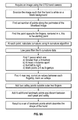
- the fingerprint camera (“Print Camera”) algorithm acquires an image from the fingerprint camera, and fingertip locations from the hand camera algorithm. If the frame is not dark, the prints can be segmented from the image. To determine if the frame is dark (“Dark Frame Detection”), the algorithm determines whether a sum of all pixels is above a threshold. If yes, then the image is passed to the Segmentation Algorithm. If it is below threshold for three consecutive frames, then processing stops.
- the fingerprint camera (“Print Camera”) algorithm acquires an image from the fingerprint camera, and fingertip locations from the hand camera algorithm. If the frame is not dark, the prints can be segmented from the image. To determine if the frame is dark (“Dark Frame Detection”), the algorithm determines whether a sum of all pixels is above a threshold. If yes, then the image is passed to the Segmentation Algorithm. If it is below threshold for three consecutive frames, then processing stops.
- the algorithm processes these segmented prints to find a more accurate print location for the next frame to be acquired.
- the fingerprint image(s) are also evaluated using a focus algorithm. The prints with the highest focus metric are retained for further processing after image acquisition is completed.
- the hand camera and fingerprint camera do not capture images at exactly the same time, hand motion perpendicular to the cameras' axis can induces a position error between the hand camera and the print camera finger positions. If the error is too high, it can be difficult to draw correspondences between fingers captured in both cameras. It can be important to draw these correspondences because, for example, the hand camera algorithm is responsible for positively numbering fingers. To account for this position error, the fingerprint camera image(s) are processed in the following way:
- the algorithm can obtain an initial box size that is used for tracking the size of the print and increasing the box size as necessary as the print grows. Further aspects include segmenting the fingers from one another. To do so, the algorithm can receive the four finger positions from the finger position correction algorithm (described above) and then proceeds to segment four prints from the Print Camera image. In some aspects, the segmented image can have a box size of about 512 ⁇ 768.
- Binarize Print Image block As well as the Focus Metric block.
- the Binarize Print Image block and the next in the chain can further refine the actual position of each print so that a good segmentation can be performed even in the presence of noise, bad lighting, and neighboring fingers. Binarization of the print involves the following steps:
- the algorithm can use curvature to again update the fingertip location in each image.
- the algorithm further processes the processing began by the binarization process by performing the following steps:
- the algorithm can additionally apply a focus metric.
- the purpose of this block is to find the single frame that contains the best focused print for each of the four fingers.
- Each segmented print is processed in the following way to create four focus metrics for each Print Camera image:
- the algorithm can retain only the image that has the highest focus metric for each finger identified. That is, if there are 4 fingers present, the image having the highest focus metric for each individual finger may be one image or could be up to four images.
- the algorithm stores in memory all of focus metric scores for each print segmentation, and a processor then compares the metrics and keeps the highest one for each finger. When image acquisition stops, this block outputs the four prints that have the highest focus metrics for that finger. These four focused prints are passed to the next section of the Print Camera algorithm for post processing. Additionally, this block can also keep track of when to stop image acquisition, stopping acquisition when the peak focus point of all fingers has been acquired. For example, the algorithm can 1) set a flag when an increase in focus has been detected for a single finger, and 2) stop image acquisition when focus decreases for all fingers three consecutive frames.
- the algorithm further processes the image(s) having the highest focus metric as described.
- the lighting used to illuminate the four fingers is not perfect. Therefore, during calibration of the on-the-go fingerprint scanners and methods described herein, a brightness map can be acquired of the lighting. This brightness map can then be used to calculate a brightness correction. Essentially, darker areas of the image(s) are gained up so that they approximately match the exposure of the bright areas.
- the algorithm can mask off neighboring fingers that do not belong to the individual print being created (i.e., if focusing on the index finger, the pinky finger can be masked off). For example, if fingers are close together, this block can remove any parts of neighboring fingers currently in the segmented print. This block can also resize the print window to better fit the particular finger.
- the following processing can be performed:
- the image(s) can be downsampled to a lower pixel per inch.
- Image resampling is simply a way to smoothly interpolate the data contained in an image, and optimally produce an image of a different size containing fewer pixels, yet still look the same.
- Downsampling can be performed by any known method, such as bilinear interpolation, and typical image resampling (i.e., downsampling) algorithms include nearest neighbor, bilinear, bicubic, as well as more advanced algorithms such as Lanczos resampling.
- the particular PPI that the image is downsampled to is dependent upon the particular application and can be any PPI desired.
- the image can be downsampled to between about 100 pixels per inch (“PPI”) and about 2000 PPI.
- the image can be downsampled to about 500 PPI.
- each print can be evaluated for “print likeness.”
- Print likeness can be evaluated using a variety of methods, including but not limited to an NFIQ score and a simplified ridge frequency detection algorithm.
- NFIQ is a complex algorithm that takes into account more aspects of the print ridges. Because of this complexity, it is better at excluding non-finger-like objects than other methods. These objects might be the wrong side of the hand, a band-aid obscuring the actual print, or an intentionally smudged finger.
- all prints receiving an NFIQ score of 5 are marked as “Not a Print.”
- the second print-likeness algorithm is based on ridge frequencies. This algorithm is designed to find where in the print segmentation box the print-like object actually is. This location can be used for things like refining the print segmentation, and excluding long fingernails.
- the ridge frequency algorithm performs the following steps.
- each print is processed for both binary and grey-level output.
- each print is cropped and centered. To do this, the algorithm can perform the following steps:
- Grey-level (or “gray-level”) processing can be performed to create a desired grey-level fingerprint output (such as that shown in FIG. 6 and FIG. 19C ).
- Grey-line processing can be performed in any manner suitable.
- a suitable processing method includes:
- the image(s) can be processed to form binarized prints, such as is shown in FIG. 6 and FIG. 18C .
- any suitable method can be used to produce binarized prints.
- a baseline method or an optional method can be utilized.
- a baseline method includes utilizing 1) a low pass Gaussian blur, and 2) adaptive threshold binarization.
- An optional method includes utilizing:
- the scanner can output said prints to an output device or user.
- the scanner can cross-reference the prints against a database of known biometric data—including fingerprints—to either obtain the identity of the subject or otherwise provide or obtain information about the subject. Additionally, the scanner can build a local database of prints and other biometric and identifying data.
- scanners can be utilized to confirm security access to buildings and other secured areas, confirm that the identity of a passenger is the same as the identity corresponding to a particular ticket, act as a form of identification or payment wherein the payment information (i.e., bank account and routing numbers) are keyed to your individual fingerprints, or any other application where a set of data is cross-referenced or checked against a scanned fingerprint.
- payment information i.e., bank account and routing numbers
- FIG. 20 shows an on-the-go fingerprint scanner having a frame 2000 holding beam break sensor 2002 that is replaced with a mirror 2004 , held in place by a mounting apparatus 2006 .
- the beam break sensor 2002 is now located on frame 2000 , and optical, imaging subsystem 2008 (including the illumination system, hand camera, and fingerprint camera) is in accordance with the above description.
- optical, imaging subsystem 2008 including the illumination system, hand camera, and fingerprint camera
- the mounting apparatus 2006 could be any of a number of configurations, in addition to that shown.
- the beam break sensor 2002 initiates the operation. Instead of a direct optical path from optical subsystem 2008 to the hand, mirror 2004 reflects the optical path back to the location of beam break sensor 2002 , now located close to optical subsystem 2008 .
- the lighting system, fingerprint camera, and hand camera systems all perform as described above.
- mirror 2008 is passive.
- Mirror 2004 is located at approximately half (1 ⁇ 2) the distance that hand break sensor 2002 was located in the aspects described above.
- mirror 2008 can be placed further away, allowing increased focal length of fingerprint camera and increased depth of field.
- the mounting apparatus 2006 can provide a folding operation to allow a more compact non-operational mode, for ease in transportation, or to reduce footprint when not operating.
- the mounting apparatus should, however, provide a stable positioning of the mirror, which can be provided by a variety of means.
- a group of items linked with the conjunction “and” should not be read as requiring that each and every one of those items be present in the grouping, but rather should be read as “and/or” unless expressly stated otherwise.
- a group of items linked with the conjunction “or” should not be read as requiring mutual exclusivity among that group, but rather should also be read as “and/or” unless expressly stated otherwise.
- items, elements or components of the invention may be described or claimed in the singular, the plural is contemplated to be within the scope thereof unless limitation to the singular is explicitly stated.
- module does not imply that the components or functionality described or claimed as part of the module are all configured in a common package. Indeed, any or all of the various components of a module, whether control logic or other components, may be combined in a single package or separately maintained and may further be distributed across multiple locations.
Abstract
Description
-
- 1) Acquire image from Print Camera;
- 2) Binarize image;
- 3) Draw line across bottom of image to connect fingers;
- 4) Find perimeter of largest blob in image;
- 5) Calculate curvature of the perimeter;
- 6) Find four highest curvature points, furthest from base of hand;
- 7) Measure distance from each highest curvature point to the finger position points passed from the Hand Camera;
- 8) Draw correspondences between finger positions and identify number of four fingers;
- 9) Measure distances from all hand finger positions to all print finger positions;
- 10) Identify direction of motion; and
- 11) Correct correspondences should have similar position errors for all fingers.
-
- 1) Binarize print image at a threshold;
- 2) Smooth edges of the binarization with erosion and dilation; and
- 3) Keep only the biggest blob, assumed to be the print.
-
- 1) Find perimeter of binary blob;
- 2) Calculate curvature of perimeter;
- 3) Find point of highest curvature; and
- 4) Update box to reflect new fingertip location and area.
-
- 1) Low Pass filter each segmented print with a Gaussian blur kernel;
- 2) Binarize; and
- 3) Sum all pixels in frame above threshold to create focus metric.
-
- 1) Binarize;
- 2) Acquire curvature of perimeter;
- 3) Shift box in original frame to center on the highest curvature, highest point close to center of current box;
- 4) If we still have a point of strong negative curvature (valley between fingers) resize box to eliminate everything outside of valley point;
- 5) If there are two valleys, do operation (4) for both sides of box;
- 6) Binarize original print, with new box size and position with Otsu's method;
- 7) Erosion and Dilation of print mask;
- 8) Fit an ellipse to the thresholded image;
- 9) Rotate image by ellipse angle so that print is approximately vertical;
- 10) Reset the bounding box left and right sides to match the fitted ellipse; and
- 11) Resize box to 1 inch in y direction (height) so you don't get too long a finger print.
-
- 1) Divide print box into blocks;
- 2) Perform a single row and single column FFT;
- 3) Create mask containing all blocks with particular box to frequency ratio; and
- 4) Erode mask.
-
- 1) Perform binary center of mass adjustment;
- 2) Cut off all four edges such that new box is 85% of old box size; and
- 3) Draw ellipse from center to the extents of the box.
At this point the algorithm, in some aspects, also flips all prints from left to right so that the prints match those captured by a traditional print reader.
-
- 1) Locally normalize raw grayscale print image;
- 2) Mask with binary print;
- 3) Invert polarity; and
- 4) Enhance contrast.
-
- 1) A low pass Gaussian blur;
- 2) Local normalization;
- 3) Adaptive threshold binarization with standard deviation offset; and
- 4) Median blur.
Claims (6)
Priority Applications (2)
| Application Number | Priority Date | Filing Date | Title |
|---|---|---|---|
| US14/620,238 US9489560B2 (en) | 2014-02-12 | 2015-02-12 | On-the go touchless fingerprint scanner |
| US15/219,400 US20170017827A1 (en) | 2014-02-12 | 2016-07-26 | On-the-go touchless fingerprint scanner |
Applications Claiming Priority (3)
| Application Number | Priority Date | Filing Date | Title |
|---|---|---|---|
| US201461938748P | 2014-02-12 | 2014-02-12 | |
| US201462092494P | 2014-12-16 | 2014-12-16 | |
| US14/620,238 US9489560B2 (en) | 2014-02-12 | 2015-02-12 | On-the go touchless fingerprint scanner |
Related Child Applications (1)
| Application Number | Title | Priority Date | Filing Date |
|---|---|---|---|
| US15/219,400 Continuation US20170017827A1 (en) | 2014-02-12 | 2016-07-26 | On-the-go touchless fingerprint scanner |
Publications (2)
| Publication Number | Publication Date |
|---|---|
| US20150227774A1 US20150227774A1 (en) | 2015-08-13 |
| US9489560B2 true US9489560B2 (en) | 2016-11-08 |
Family
ID=53775194
Family Applications (2)
| Application Number | Title | Priority Date | Filing Date |
|---|---|---|---|
| US14/620,238 Expired - Fee Related US9489560B2 (en) | 2014-02-12 | 2015-02-12 | On-the go touchless fingerprint scanner |
| US15/219,400 Abandoned US20170017827A1 (en) | 2014-02-12 | 2016-07-26 | On-the-go touchless fingerprint scanner |
Family Applications After (1)
| Application Number | Title | Priority Date | Filing Date |
|---|---|---|---|
| US15/219,400 Abandoned US20170017827A1 (en) | 2014-02-12 | 2016-07-26 | On-the-go touchless fingerprint scanner |
Country Status (2)
| Country | Link |
|---|---|
| US (2) | US9489560B2 (en) |
| CA (1) | CA2939637A1 (en) |
Cited By (2)
| Publication number | Priority date | Publication date | Assignee | Title |
|---|---|---|---|---|
| US20190266377A1 (en) * | 2006-04-26 | 2019-08-29 | Aware, Inc. | Fingerprint preview quality and segmentation |
| US11531756B1 (en) | 2017-03-20 | 2022-12-20 | Hid Global Corporation | Apparatus for directing presentation attack detection in biometric scanners |
Families Citing this family (21)
| Publication number | Priority date | Publication date | Assignee | Title |
|---|---|---|---|---|
| US9213781B1 (en) | 2012-09-19 | 2015-12-15 | Placemeter LLC | System and method for processing image data |
| US11373439B1 (en) | 2013-03-14 | 2022-06-28 | Telos Corporation | Touchless fingerprint matching systems and methods |
| US9710691B1 (en) * | 2014-01-23 | 2017-07-18 | Diamond Fortress Technologies, Inc. | Touchless fingerprint matching systems and methods |
| JP2017525064A (en) | 2014-05-30 | 2017-08-31 | プレイスメーター インコーポレイテッドPlacemeter Inc. | System and method for activity monitoring using video data |
| US11263432B2 (en) * | 2015-02-06 | 2022-03-01 | Veridium Ip Limited | Systems and methods for performing fingerprint based user authentication using imagery captured using mobile devices |
| US9424458B1 (en) * | 2015-02-06 | 2016-08-23 | Hoyos Labs Ip Ltd. | Systems and methods for performing fingerprint based user authentication using imagery captured using mobile devices |
| US9361507B1 (en) * | 2015-02-06 | 2016-06-07 | Hoyos Labs Ip Ltd. | Systems and methods for performing fingerprint based user authentication using imagery captured using mobile devices |
| US10043078B2 (en) | 2015-04-21 | 2018-08-07 | Placemeter LLC | Virtual turnstile system and method |
| CN105518708B (en) * | 2015-04-29 | 2018-06-12 | 北京旷视科技有限公司 | For verifying the method for living body faces, equipment and computer program product |
| US11138442B2 (en) | 2015-06-01 | 2021-10-05 | Placemeter, Inc. | Robust, adaptive and efficient object detection, classification and tracking |
| US10242427B2 (en) * | 2016-07-29 | 2019-03-26 | Massachusetts Institute Of Technology | Deviation magnification: revealing departures from ideal geometries |
| CN107194331B (en) * | 2017-05-08 | 2019-04-12 | 维沃移动通信有限公司 | A kind of fingerprint identification method and mobile terminal |
| US11507646B1 (en) * | 2017-09-29 | 2022-11-22 | Amazon Technologies, Inc. | User authentication using video analysis |
| CN108154141B (en) * | 2018-01-24 | 2021-09-07 | 江再玉 | Biological parameter identification system using finger veins |
| ES2837382T3 (en) * | 2018-03-16 | 2021-06-30 | Identy Inc | Procedure to identify an object within an image and mobile device to execute the procedure |
| AT521934A1 (en) * | 2018-12-05 | 2020-06-15 | Ait Austrian Inst Tech Gmbh | Procedure for capturing fingerprints |
| US10984219B2 (en) * | 2019-07-19 | 2021-04-20 | Idmission, Llc | Fingerprint processing with liveness detection |
| DE102020200569A1 (en) | 2020-01-17 | 2021-07-22 | Brno University of Technology | Device for biometric identification with the aid of fingerprints and / or hand characteristics and methods for biometric identification with the aid of these characteristics |
| CN111400689A (en) * | 2020-03-25 | 2020-07-10 | Oppo广东移动通信有限公司 | Terminal unlocking method and device, storage medium and terminal |
| WO2021206736A1 (en) * | 2020-04-10 | 2021-10-14 | Hewlett-Packard Development Company, L.P. | Fluid ejection device testing |
| FR3113152B1 (en) * | 2020-07-30 | 2023-10-06 | Idemia Identity & Security France | Biometric terminal, in particular for access control |
Citations (24)
| Publication number | Priority date | Publication date | Assignee | Title |
|---|---|---|---|---|
| US5929443A (en) | 1995-12-18 | 1999-07-27 | The Research Foundation City College Of New York | Imaging of objects based upon the polarization or depolarization of light |
| US20010026632A1 (en) | 2000-03-24 | 2001-10-04 | Seiichiro Tamai | Apparatus for identity verification, a system for identity verification, a card for identity verification and a method for identity verification, based on identification by biometrics |
| US20010041073A1 (en) | 2000-02-03 | 2001-11-15 | Noam Sorek | Active aid for a handheld camera |
| US6404904B1 (en) | 1998-04-24 | 2002-06-11 | Tst-Touchless Sensor Technology Ag | System for the touchless recognition of hand and finger lines |
| US20050226474A1 (en) | 2003-10-08 | 2005-10-13 | Tbs Holding Ag | Touchless biometric recognition |
| US20050265586A1 (en) | 2004-06-01 | 2005-12-01 | Lumidigm, Inc. | Multispectral biometric imaging |
| US20060113381A1 (en) | 2004-11-29 | 2006-06-01 | John Hochstein | Batteryless contact fingerprint-enabled smartcard that enables contactless capability |
| US20070040017A1 (en) | 2005-08-22 | 2007-02-22 | Douglas Kozlay | Wireless biometric cardholder apparatus, method, & system |
| US20070131759A1 (en) | 2005-12-14 | 2007-06-14 | Cox Mark A | Smartcard and magnetic stripe emulator with biometric authentication |
| US20080080751A1 (en) | 2006-10-02 | 2008-04-03 | Wison Technology Corp. | Method of capturing fingerprint image |
| US7397943B2 (en) | 2003-04-08 | 2008-07-08 | Tbs Holding Ag | Method and arrangement for touchless detection of data of uneven surfaces |
| US20080219522A1 (en) | 2007-03-09 | 2008-09-11 | Authentec, Inc. | Finger sensor using polarized light and associated methods |
| US7587071B2 (en) | 2001-06-13 | 2009-09-08 | Tst Biometrics Holding Ag | Method and device for recognition of natural skin during contact-free biometric identification of a person |
| US20090245591A1 (en) | 2006-07-19 | 2009-10-01 | Lumidigm, Inc. | Contactless Multispectral Biometric Capture |
| US7599531B2 (en) | 2004-08-24 | 2009-10-06 | Tbs Holding Ag | Method and arrangement for optical recording of biometric finger data |
| US20100014717A1 (en) | 2008-07-21 | 2010-01-21 | Airborne Biometrics Group, Inc. | Managed Biometric-Based Notification System and Method |
| US7660442B2 (en) | 2006-09-01 | 2010-02-09 | Handshot, Llc | Method and system for capturing fingerprints, palm prints and hand geometry |
| US20100165090A1 (en) | 2008-07-25 | 2010-07-01 | Sweeney Latanya A | Frontal Hand Capture of Fingerprints, Palm Prints and Hand Geometry Using Contactless Photography |
| US20100172548A1 (en) | 2006-09-19 | 2010-07-08 | Mil Shtein Samson | Circumferential Contact-Less Line Scanning of Biometric Objects |
| US7812963B2 (en) | 2002-09-09 | 2010-10-12 | Zygo Corporation | Interferometry method for ellipsometry, reflectometry, and scatterometry measurements, including characterization of thin film structures |
| US20110279663A1 (en) | 2010-05-12 | 2011-11-17 | Vision Bright, Incorporated | Real-time embedded vision-based human hand detection |
| US20120016798A1 (en) | 2010-07-13 | 2012-01-19 | Tec Solutions, Inc. | Biometric authentication system and biometric sensor configured for single user authentication |
| US20120076369A1 (en) | 2010-09-24 | 2012-03-29 | Gil Abramovich | System and method for contactless multi-fingerprint collection |
| US20120086794A1 (en) | 2010-10-08 | 2012-04-12 | Advanced Optical Systems, Inc | Contactless fingerprint acquisition and processing |
-
2015
- 2015-02-12 CA CA2939637A patent/CA2939637A1/en not_active Abandoned
- 2015-02-12 US US14/620,238 patent/US9489560B2/en not_active Expired - Fee Related
-
2016
- 2016-07-26 US US15/219,400 patent/US20170017827A1/en not_active Abandoned
Patent Citations (24)
| Publication number | Priority date | Publication date | Assignee | Title |
|---|---|---|---|---|
| US5929443A (en) | 1995-12-18 | 1999-07-27 | The Research Foundation City College Of New York | Imaging of objects based upon the polarization or depolarization of light |
| US6404904B1 (en) | 1998-04-24 | 2002-06-11 | Tst-Touchless Sensor Technology Ag | System for the touchless recognition of hand and finger lines |
| US20010041073A1 (en) | 2000-02-03 | 2001-11-15 | Noam Sorek | Active aid for a handheld camera |
| US20010026632A1 (en) | 2000-03-24 | 2001-10-04 | Seiichiro Tamai | Apparatus for identity verification, a system for identity verification, a card for identity verification and a method for identity verification, based on identification by biometrics |
| US7587071B2 (en) | 2001-06-13 | 2009-09-08 | Tst Biometrics Holding Ag | Method and device for recognition of natural skin during contact-free biometric identification of a person |
| US7812963B2 (en) | 2002-09-09 | 2010-10-12 | Zygo Corporation | Interferometry method for ellipsometry, reflectometry, and scatterometry measurements, including characterization of thin film structures |
| US7397943B2 (en) | 2003-04-08 | 2008-07-08 | Tbs Holding Ag | Method and arrangement for touchless detection of data of uneven surfaces |
| US20050226474A1 (en) | 2003-10-08 | 2005-10-13 | Tbs Holding Ag | Touchless biometric recognition |
| US20050265586A1 (en) | 2004-06-01 | 2005-12-01 | Lumidigm, Inc. | Multispectral biometric imaging |
| US7599531B2 (en) | 2004-08-24 | 2009-10-06 | Tbs Holding Ag | Method and arrangement for optical recording of biometric finger data |
| US20060113381A1 (en) | 2004-11-29 | 2006-06-01 | John Hochstein | Batteryless contact fingerprint-enabled smartcard that enables contactless capability |
| US20070040017A1 (en) | 2005-08-22 | 2007-02-22 | Douglas Kozlay | Wireless biometric cardholder apparatus, method, & system |
| US20070131759A1 (en) | 2005-12-14 | 2007-06-14 | Cox Mark A | Smartcard and magnetic stripe emulator with biometric authentication |
| US20090245591A1 (en) | 2006-07-19 | 2009-10-01 | Lumidigm, Inc. | Contactless Multispectral Biometric Capture |
| US7660442B2 (en) | 2006-09-01 | 2010-02-09 | Handshot, Llc | Method and system for capturing fingerprints, palm prints and hand geometry |
| US20100172548A1 (en) | 2006-09-19 | 2010-07-08 | Mil Shtein Samson | Circumferential Contact-Less Line Scanning of Biometric Objects |
| US20080080751A1 (en) | 2006-10-02 | 2008-04-03 | Wison Technology Corp. | Method of capturing fingerprint image |
| US20080219522A1 (en) | 2007-03-09 | 2008-09-11 | Authentec, Inc. | Finger sensor using polarized light and associated methods |
| US20100014717A1 (en) | 2008-07-21 | 2010-01-21 | Airborne Biometrics Group, Inc. | Managed Biometric-Based Notification System and Method |
| US20100165090A1 (en) | 2008-07-25 | 2010-07-01 | Sweeney Latanya A | Frontal Hand Capture of Fingerprints, Palm Prints and Hand Geometry Using Contactless Photography |
| US20110279663A1 (en) | 2010-05-12 | 2011-11-17 | Vision Bright, Incorporated | Real-time embedded vision-based human hand detection |
| US20120016798A1 (en) | 2010-07-13 | 2012-01-19 | Tec Solutions, Inc. | Biometric authentication system and biometric sensor configured for single user authentication |
| US20120076369A1 (en) | 2010-09-24 | 2012-03-29 | Gil Abramovich | System and method for contactless multi-fingerprint collection |
| US20120086794A1 (en) | 2010-10-08 | 2012-04-12 | Advanced Optical Systems, Inc | Contactless fingerprint acquisition and processing |
Non-Patent Citations (5)
| Title |
|---|
| International Preliminary Report on Patentability for International Patent Application No. PCT/US2011/055192 filed Oct. 7, 2011, 6 pages. |
| International Search Report for International Application No. PCT/US15/15538; International Filing Date: Feb. 12, 2015; Date of Mailing Jun. 3, 2015; 7 pgs. |
| International Search Report for International Patent Application No. PCT/US2011/055192 filed Oct. 7, 2011. |
| Written Opinion for International Patent Application No. PCT/US2011/055192 filed Oct. 7, 2011. |
| Written Opinion of the International Searching Authority for International Application No. PCT/US15/15538; International Filing Date: Februry 12, 2015; Date of Mailing: Jun. 3, 2015; 4 pages. |
Cited By (4)
| Publication number | Priority date | Publication date | Assignee | Title |
|---|---|---|---|---|
| US20190266377A1 (en) * | 2006-04-26 | 2019-08-29 | Aware, Inc. | Fingerprint preview quality and segmentation |
| US10776604B2 (en) * | 2006-04-26 | 2020-09-15 | Aware, Inc. | Fingerprint preview quality and segmentation |
| US11250239B2 (en) | 2006-04-26 | 2022-02-15 | Aware, Inc. | Fingerprint preview quality and segmentation |
| US11531756B1 (en) | 2017-03-20 | 2022-12-20 | Hid Global Corporation | Apparatus for directing presentation attack detection in biometric scanners |
Also Published As
| Publication number | Publication date |
|---|---|
| US20150227774A1 (en) | 2015-08-13 |
| CA2939637A1 (en) | 2015-08-20 |
| US20170017827A1 (en) | 2017-01-19 |
Similar Documents
| Publication | Publication Date | Title |
|---|---|---|
| US9489560B2 (en) | On-the go touchless fingerprint scanner | |
| KR102587193B1 (en) | System and method for performing fingerprint-based user authentication using images captured using a mobile device | |
| US9959478B2 (en) | Method and system for biometric recognition | |
| US8803963B2 (en) | Vein pattern recognition based biometric system and methods thereof | |
| KR101683712B1 (en) | An iris and ocular recognition system using trace transforms | |
| RU2431190C2 (en) | Facial prominence recognition method and device | |
| JP2020501264A (en) | System and method for performing fingerprint authentication using images captured with a mobile device | |
| JP2006302276A (en) | Automated, non-invasive iris recognition system and method | |
| JP2009544108A (en) | Multispectral image for multiple biometric authentication | |
| JP2000259814A (en) | Image processor and method therefor | |
| CN112232155B (en) | Non-contact fingerprint identification method and device, terminal and storage medium | |
| CN112232163B (en) | Fingerprint acquisition method and device, fingerprint comparison method and device, and equipment | |
| Matey et al. | Iris recognition in less constrained environments | |
| CN112016525A (en) | Non-contact fingerprint acquisition method and device | |
| US11080511B2 (en) | Contactless rolled fingerprints | |
| CN112232159A (en) | Fingerprint identification method, device, terminal and storage medium | |
| Parziale et al. | Advanced technologies for touchless fingerprint recognition | |
| EP3105712A1 (en) | On-the-go touchless fingerprint scanner | |
| US20220121869A1 (en) | Biometric authentication device and biometric authentication method | |
| CN112232157B (en) | Fingerprint area detection method, device, equipment and storage medium | |
| CN112668539A (en) | Biological characteristic acquisition and identification system and method, terminal equipment and storage medium | |
| Bashir et al. | Video surveillance for biometrics: long-range multi-biometric system | |
| CN112232152B (en) | Non-contact fingerprint identification method and device, terminal and storage medium | |
| KR102237458B1 (en) | Apparatus for recognizing iris and operating method thereof | |
| Yoo et al. | A simply integrated dual-sensor based non-intrusive iris image acquisition system |
Legal Events
| Date | Code | Title | Description |
|---|---|---|---|
| AS | Assignment |
Owner name: ADVANCED OPTICAL SYSTEMS, INC., ALABAMA Free format text: ASSIGNMENT OF ASSIGNORS INTEREST;ASSIGNORS:BALCH, MICHAEL KEVIN;FOX, STEPHEN HARRIS;HARTMAN, RICHARD LEON;AND OTHERS;SIGNING DATES FROM 20150210 TO 20150211;REEL/FRAME:034970/0700 |
|
| FEPP | Fee payment procedure |
Free format text: ENTITY STATUS SET TO SMALL (ORIGINAL EVENT CODE: SMAL); ENTITY STATUS OF PATENT OWNER: SMALL ENTITY |
|
| STCF | Information on status: patent grant |
Free format text: PATENTED CASE |
|
| FEPP | Fee payment procedure |
Free format text: MAINTENANCE FEE REMINDER MAILED (ORIGINAL EVENT CODE: REM.); ENTITY STATUS OF PATENT OWNER: SMALL ENTITY |
|
| LAPS | Lapse for failure to pay maintenance fees |
Free format text: PATENT EXPIRED FOR FAILURE TO PAY MAINTENANCE FEES (ORIGINAL EVENT CODE: EXP.); ENTITY STATUS OF PATENT OWNER: SMALL ENTITY |
|
| STCH | Information on status: patent discontinuation |
Free format text: PATENT EXPIRED DUE TO NONPAYMENT OF MAINTENANCE FEES UNDER 37 CFR 1.362 |
|
| FP | Lapsed due to failure to pay maintenance fee |
Effective date: 20201108 |
|
| AS | Assignment |
Owner name: ZEROCONZERO, LLC, ALABAMA Free format text: ASSIGNMENT OF ASSIGNORS INTEREST;ASSIGNOR:ESTATE OF DOROTHY CAROLYN SMITH DAVIDSON;REEL/FRAME:062807/0401 Effective date: 20220630 |
|
| FEPP | Fee payment procedure |
Free format text: PETITION RELATED TO MAINTENANCE FEES FILED (ORIGINAL EVENT CODE: PMFP); ENTITY STATUS OF PATENT OWNER: SMALL ENTITY |
|
| FEPP | Fee payment procedure |
Free format text: PETITION RELATED TO MAINTENANCE FEES DISMISSED (ORIGINAL EVENT CODE: PMFS); ENTITY STATUS OF PATENT OWNER: SMALL ENTITY |
|
| AS | Assignment |
Owner name: DOROTHY DAVIDSON, ALABAMA Free format text: PURCHASE OF SECURITY INTEREST;ASSIGNOR:FIRST COMMERCIAL BANK, A DIVISION OF SYNOVUS BANK;REEL/FRAME:065890/0320 Effective date: 20180323 |