US9492599B2 - Hall sensor mounting in an implantable blood pump - Google Patents
Hall sensor mounting in an implantable blood pump Download PDFInfo
- Publication number
- US9492599B2 US9492599B2 US14/015,542 US201314015542A US9492599B2 US 9492599 B2 US9492599 B2 US 9492599B2 US 201314015542 A US201314015542 A US 201314015542A US 9492599 B2 US9492599 B2 US 9492599B2
- Authority
- US
- United States
- Prior art keywords
- rotor
- circuit board
- printed circuit
- molded interconnect
- stator
- Prior art date
- Legal status (The legal status is an assumption and is not a legal conclusion. Google has not performed a legal analysis and makes no representation as to the accuracy of the status listed.)
- Active, expires
Links
- 210000004369 blood Anatomy 0.000 title claims abstract description 73
- 239000008280 blood Substances 0.000 title claims abstract description 73
- 230000002463 transducing effect Effects 0.000 claims abstract description 4
- 230000017531 blood circulation Effects 0.000 claims description 54
- 230000005291 magnetic effect Effects 0.000 claims description 40
- 239000000853 adhesive Substances 0.000 claims description 25
- 230000001070 adhesive effect Effects 0.000 claims description 25
- 238000000034 method Methods 0.000 claims description 23
- 238000005339 levitation Methods 0.000 claims description 17
- 238000003780 insertion Methods 0.000 claims description 3
- 230000037431 insertion Effects 0.000 claims description 3
- 230000002093 peripheral effect Effects 0.000 description 23
- XEEYBQQBJWHFJM-UHFFFAOYSA-N Iron Chemical compound [Fe] XEEYBQQBJWHFJM-UHFFFAOYSA-N 0.000 description 18
- 238000013461 design Methods 0.000 description 12
- 239000000463 material Substances 0.000 description 8
- 229910052742 iron Inorganic materials 0.000 description 6
- 239000004593 Epoxy Substances 0.000 description 5
- 230000008569 process Effects 0.000 description 5
- JPOPEORRMSDUIP-UHFFFAOYSA-N 1,2,4,5-tetrachloro-3-(2,3,5,6-tetrachlorophenyl)benzene Chemical compound ClC1=CC(Cl)=C(Cl)C(C=2C(=C(Cl)C=C(Cl)C=2Cl)Cl)=C1Cl JPOPEORRMSDUIP-UHFFFAOYSA-N 0.000 description 4
- 230000008901 benefit Effects 0.000 description 4
- 230000005672 electromagnetic field Effects 0.000 description 4
- 230000007704 transition Effects 0.000 description 4
- 238000007588 break-off test Methods 0.000 description 3
- 238000004891 communication Methods 0.000 description 3
- 239000012530 fluid Substances 0.000 description 3
- 239000007788 liquid Substances 0.000 description 3
- 230000007935 neutral effect Effects 0.000 description 3
- 238000003466 welding Methods 0.000 description 3
- KGSSUTVUTPLSQW-UHFFFAOYSA-N Robustone Chemical compound C1=C2OCOC2=CC(C2=COC=3C=C4OC(C=CC4=C(O)C=3C2=O)(C)C)=C1 KGSSUTVUTPLSQW-UHFFFAOYSA-N 0.000 description 2
- 230000009471 action Effects 0.000 description 2
- 230000004075 alteration Effects 0.000 description 2
- 210000000601 blood cell Anatomy 0.000 description 2
- 230000000694 effects Effects 0.000 description 2
- 239000003302 ferromagnetic material Substances 0.000 description 2
- 230000004907 flux Effects 0.000 description 2
- 238000010348 incorporation Methods 0.000 description 2
- 230000003993 interaction Effects 0.000 description 2
- 229910000679 solder Inorganic materials 0.000 description 2
- 238000001356 surgical procedure Methods 0.000 description 2
- 239000000725 suspension Substances 0.000 description 2
- 230000002861 ventricular Effects 0.000 description 2
- 206010007559 Cardiac failure congestive Diseases 0.000 description 1
- 206010019280 Heart failures Diseases 0.000 description 1
- 229910000831 Steel Inorganic materials 0.000 description 1
- 210000001015 abdomen Anatomy 0.000 description 1
- 230000008859 change Effects 0.000 description 1
- 230000004087 circulation Effects 0.000 description 1
- 230000035602 clotting Effects 0.000 description 1
- 239000011248 coating agent Substances 0.000 description 1
- 238000000576 coating method Methods 0.000 description 1
- 239000004020 conductor Substances 0.000 description 1
- 239000013078 crystal Substances 0.000 description 1
- 230000006870 function Effects 0.000 description 1
- 230000004217 heart function Effects 0.000 description 1
- 230000017525 heat dissipation Effects 0.000 description 1
- 230000001788 irregular Effects 0.000 description 1
- 238000005304 joining Methods 0.000 description 1
- 210000005240 left ventricle Anatomy 0.000 description 1
- 230000007774 longterm Effects 0.000 description 1
- 238000004519 manufacturing process Methods 0.000 description 1
- 230000007246 mechanism Effects 0.000 description 1
- 238000012986 modification Methods 0.000 description 1
- 230000004048 modification Effects 0.000 description 1
- 238000012544 monitoring process Methods 0.000 description 1
- 229920000642 polymer Polymers 0.000 description 1
- 238000004382 potting Methods 0.000 description 1
- 238000005086 pumping Methods 0.000 description 1
- 238000011084 recovery Methods 0.000 description 1
- 239000004447 silicone coating Substances 0.000 description 1
- 230000003068 static effect Effects 0.000 description 1
- 239000010959 steel Substances 0.000 description 1
- 238000006467 substitution reaction Methods 0.000 description 1
- 239000013589 supplement Substances 0.000 description 1
- 238000012360 testing method Methods 0.000 description 1
- 238000005382 thermal cycling Methods 0.000 description 1
- 238000011144 upstream manufacturing Methods 0.000 description 1
- 238000004804 winding Methods 0.000 description 1
Images


Classifications
-
- A61M1/12—
-
- A61M1/1086—
-
- A61M1/122—
-
- A—HUMAN NECESSITIES
- A61—MEDICAL OR VETERINARY SCIENCE; HYGIENE
- A61M—DEVICES FOR INTRODUCING MEDIA INTO, OR ONTO, THE BODY; DEVICES FOR TRANSDUCING BODY MEDIA OR FOR TAKING MEDIA FROM THE BODY; DEVICES FOR PRODUCING OR ENDING SLEEP OR STUPOR
- A61M60/00—Blood pumps; Devices for mechanical circulatory actuation; Balloon pumps for circulatory assistance
- A61M60/10—Location thereof with respect to the patient's body
- A61M60/122—Implantable pumps or pumping devices, i.e. the blood being pumped inside the patient's body
- A61M60/126—Implantable pumps or pumping devices, i.e. the blood being pumped inside the patient's body implantable via, into, inside, in line, branching on, or around a blood vessel
- A61M60/148—Implantable pumps or pumping devices, i.e. the blood being pumped inside the patient's body implantable via, into, inside, in line, branching on, or around a blood vessel in line with a blood vessel using resection or like techniques, e.g. permanent endovascular heart assist devices
-
- A—HUMAN NECESSITIES
- A61—MEDICAL OR VETERINARY SCIENCE; HYGIENE
- A61M—DEVICES FOR INTRODUCING MEDIA INTO, OR ONTO, THE BODY; DEVICES FOR TRANSDUCING BODY MEDIA OR FOR TAKING MEDIA FROM THE BODY; DEVICES FOR PRODUCING OR ENDING SLEEP OR STUPOR
- A61M60/00—Blood pumps; Devices for mechanical circulatory actuation; Balloon pumps for circulatory assistance
- A61M60/10—Location thereof with respect to the patient's body
- A61M60/122—Implantable pumps or pumping devices, i.e. the blood being pumped inside the patient's body
- A61M60/165—Implantable pumps or pumping devices, i.e. the blood being pumped inside the patient's body implantable in, on, or around the heart
- A61M60/178—Implantable pumps or pumping devices, i.e. the blood being pumped inside the patient's body implantable in, on, or around the heart drawing blood from a ventricle and returning the blood to the arterial system via a cannula external to the ventricle, e.g. left or right ventricular assist devices
-
- A—HUMAN NECESSITIES
- A61—MEDICAL OR VETERINARY SCIENCE; HYGIENE
- A61M—DEVICES FOR INTRODUCING MEDIA INTO, OR ONTO, THE BODY; DEVICES FOR TRANSDUCING BODY MEDIA OR FOR TAKING MEDIA FROM THE BODY; DEVICES FOR PRODUCING OR ENDING SLEEP OR STUPOR
- A61M60/00—Blood pumps; Devices for mechanical circulatory actuation; Balloon pumps for circulatory assistance
- A61M60/20—Type thereof
- A61M60/205—Non-positive displacement blood pumps
- A61M60/216—Non-positive displacement blood pumps including a rotating member acting on the blood, e.g. impeller
-
- A—HUMAN NECESSITIES
- A61—MEDICAL OR VETERINARY SCIENCE; HYGIENE
- A61M—DEVICES FOR INTRODUCING MEDIA INTO, OR ONTO, THE BODY; DEVICES FOR TRANSDUCING BODY MEDIA OR FOR TAKING MEDIA FROM THE BODY; DEVICES FOR PRODUCING OR ENDING SLEEP OR STUPOR
- A61M60/00—Blood pumps; Devices for mechanical circulatory actuation; Balloon pumps for circulatory assistance
- A61M60/40—Details relating to driving
- A61M60/403—Details relating to driving for non-positive displacement blood pumps
- A61M60/419—Details relating to driving for non-positive displacement blood pumps the force acting on the blood contacting member being permanent magnetic, e.g. from a rotating magnetic coupling between driving and driven magnets
-
- A—HUMAN NECESSITIES
- A61—MEDICAL OR VETERINARY SCIENCE; HYGIENE
- A61M—DEVICES FOR INTRODUCING MEDIA INTO, OR ONTO, THE BODY; DEVICES FOR TRANSDUCING BODY MEDIA OR FOR TAKING MEDIA FROM THE BODY; DEVICES FOR PRODUCING OR ENDING SLEEP OR STUPOR
- A61M60/00—Blood pumps; Devices for mechanical circulatory actuation; Balloon pumps for circulatory assistance
- A61M60/40—Details relating to driving
- A61M60/403—Details relating to driving for non-positive displacement blood pumps
- A61M60/422—Details relating to driving for non-positive displacement blood pumps the force acting on the blood contacting member being electromagnetic, e.g. using canned motor pumps
-
- A—HUMAN NECESSITIES
- A61—MEDICAL OR VETERINARY SCIENCE; HYGIENE
- A61M—DEVICES FOR INTRODUCING MEDIA INTO, OR ONTO, THE BODY; DEVICES FOR TRANSDUCING BODY MEDIA OR FOR TAKING MEDIA FROM THE BODY; DEVICES FOR PRODUCING OR ENDING SLEEP OR STUPOR
- A61M60/00—Blood pumps; Devices for mechanical circulatory actuation; Balloon pumps for circulatory assistance
- A61M60/50—Details relating to control
- A61M60/508—Electronic control means, e.g. for feedback regulation
- A61M60/515—Regulation using real-time patient data
-
- A—HUMAN NECESSITIES
- A61—MEDICAL OR VETERINARY SCIENCE; HYGIENE
- A61M—DEVICES FOR INTRODUCING MEDIA INTO, OR ONTO, THE BODY; DEVICES FOR TRANSDUCING BODY MEDIA OR FOR TAKING MEDIA FROM THE BODY; DEVICES FOR PRODUCING OR ENDING SLEEP OR STUPOR
- A61M60/00—Blood pumps; Devices for mechanical circulatory actuation; Balloon pumps for circulatory assistance
- A61M60/50—Details relating to control
- A61M60/508—Electronic control means, e.g. for feedback regulation
- A61M60/538—Regulation using real-time blood pump operational parameter data, e.g. motor current
-
- F—MECHANICAL ENGINEERING; LIGHTING; HEATING; WEAPONS; BLASTING
- F04—POSITIVE - DISPLACEMENT MACHINES FOR LIQUIDS; PUMPS FOR LIQUIDS OR ELASTIC FLUIDS
- F04D—NON-POSITIVE-DISPLACEMENT PUMPS
- F04D13/00—Pumping installations or systems
- F04D13/02—Units comprising pumps and their driving means
- F04D13/06—Units comprising pumps and their driving means the pump being electrically driven
- F04D13/0606—Canned motor pumps
- F04D13/064—Details of the magnetic circuit
-
- F—MECHANICAL ENGINEERING; LIGHTING; HEATING; WEAPONS; BLASTING
- F04—POSITIVE - DISPLACEMENT MACHINES FOR LIQUIDS; PUMPS FOR LIQUIDS OR ELASTIC FLUIDS
- F04D—NON-POSITIVE-DISPLACEMENT PUMPS
- F04D15/00—Control, e.g. regulation, of pumps, pumping installations or systems
- F04D15/0077—Safety measures
-
- G—PHYSICS
- G01—MEASURING; TESTING
- G01B—MEASURING LENGTH, THICKNESS OR SIMILAR LINEAR DIMENSIONS; MEASURING ANGLES; MEASURING AREAS; MEASURING IRREGULARITIES OF SURFACES OR CONTOURS
- G01B7/00—Measuring arrangements characterised by the use of electric or magnetic techniques
- G01B7/003—Measuring arrangements characterised by the use of electric or magnetic techniques for measuring position, not involving coordinate determination
-
- G—PHYSICS
- G01—MEASURING; TESTING
- G01B—MEASURING LENGTH, THICKNESS OR SIMILAR LINEAR DIMENSIONS; MEASURING ANGLES; MEASURING AREAS; MEASURING IRREGULARITIES OF SURFACES OR CONTOURS
- G01B7/00—Measuring arrangements characterised by the use of electric or magnetic techniques
- G01B7/30—Measuring arrangements characterised by the use of electric or magnetic techniques for measuring angles or tapers; for testing the alignment of axes
-
- G—PHYSICS
- G01—MEASURING; TESTING
- G01D—MEASURING NOT SPECIALLY ADAPTED FOR A SPECIFIC VARIABLE; ARRANGEMENTS FOR MEASURING TWO OR MORE VARIABLES NOT COVERED IN A SINGLE OTHER SUBCLASS; TARIFF METERING APPARATUS; MEASURING OR TESTING NOT OTHERWISE PROVIDED FOR
- G01D5/00—Mechanical means for transferring the output of a sensing member; Means for converting the output of a sensing member to another variable where the form or nature of the sensing member does not constrain the means for converting; Transducers not specially adapted for a specific variable
- G01D5/12—Mechanical means for transferring the output of a sensing member; Means for converting the output of a sensing member to another variable where the form or nature of the sensing member does not constrain the means for converting; Transducers not specially adapted for a specific variable using electric or magnetic means
- G01D5/14—Mechanical means for transferring the output of a sensing member; Means for converting the output of a sensing member to another variable where the form or nature of the sensing member does not constrain the means for converting; Transducers not specially adapted for a specific variable using electric or magnetic means influencing the magnitude of a current or voltage
- G01D5/142—Mechanical means for transferring the output of a sensing member; Means for converting the output of a sensing member to another variable where the form or nature of the sensing member does not constrain the means for converting; Transducers not specially adapted for a specific variable using electric or magnetic means influencing the magnitude of a current or voltage using Hall-effect devices
-
- G—PHYSICS
- G01—MEASURING; TESTING
- G01R—MEASURING ELECTRIC VARIABLES; MEASURING MAGNETIC VARIABLES
- G01R33/00—Arrangements or instruments for measuring magnetic variables
- G01R33/02—Measuring direction or magnitude of magnetic fields or magnetic flux
- G01R33/06—Measuring direction or magnitude of magnetic fields or magnetic flux using galvano-magnetic devices
- G01R33/07—Hall effect devices
- G01R33/072—Constructional adaptation of the sensor to specific applications
-
- H—ELECTRICITY
- H05—ELECTRIC TECHNIQUES NOT OTHERWISE PROVIDED FOR
- H05K—PRINTED CIRCUITS; CASINGS OR CONSTRUCTIONAL DETAILS OF ELECTRIC APPARATUS; MANUFACTURE OF ASSEMBLAGES OF ELECTRICAL COMPONENTS
- H05K1/00—Printed circuits
- H05K1/02—Details
- H05K1/0277—Bendability or stretchability details
- H05K1/028—Bending or folding regions of flexible printed circuits
-
- H—ELECTRICITY
- H05—ELECTRIC TECHNIQUES NOT OTHERWISE PROVIDED FOR
- H05K—PRINTED CIRCUITS; CASINGS OR CONSTRUCTIONAL DETAILS OF ELECTRIC APPARATUS; MANUFACTURE OF ASSEMBLAGES OF ELECTRICAL COMPONENTS
- H05K1/00—Printed circuits
- H05K1/02—Details
- H05K1/11—Printed elements for providing electric connections to or between printed circuits
- H05K1/119—Details of rigid insulating substrates therefor, e.g. three-dimensional details
-
- H—ELECTRICITY
- H05—ELECTRIC TECHNIQUES NOT OTHERWISE PROVIDED FOR
- H05K—PRINTED CIRCUITS; CASINGS OR CONSTRUCTIONAL DETAILS OF ELECTRIC APPARATUS; MANUFACTURE OF ASSEMBLAGES OF ELECTRICAL COMPONENTS
- H05K1/00—Printed circuits
- H05K1/18—Printed circuits structurally associated with non-printed electric components
- H05K1/189—Printed circuits structurally associated with non-printed electric components characterised by the use of a flexible or folded printed circuit
-
- H—ELECTRICITY
- H05—ELECTRIC TECHNIQUES NOT OTHERWISE PROVIDED FOR
- H05K—PRINTED CIRCUITS; CASINGS OR CONSTRUCTIONAL DETAILS OF ELECTRIC APPARATUS; MANUFACTURE OF ASSEMBLAGES OF ELECTRICAL COMPONENTS
- H05K3/00—Apparatus or processes for manufacturing printed circuits
- H05K3/30—Assembling printed circuits with electric components, e.g. with resistor
- H05K3/303—Surface mounted components, e.g. affixing before soldering, aligning means, spacing means
-
- H—ELECTRICITY
- H05—ELECTRIC TECHNIQUES NOT OTHERWISE PROVIDED FOR
- H05K—PRINTED CIRCUITS; CASINGS OR CONSTRUCTIONAL DETAILS OF ELECTRIC APPARATUS; MANUFACTURE OF ASSEMBLAGES OF ELECTRICAL COMPONENTS
- H05K3/00—Apparatus or processes for manufacturing printed circuits
- H05K3/30—Assembling printed circuits with electric components, e.g. with resistor
- H05K3/32—Assembling printed circuits with electric components, e.g. with resistor electrically connecting electric components or wires to printed circuits
-
- A61M1/1031—
-
- A—HUMAN NECESSITIES
- A61—MEDICAL OR VETERINARY SCIENCE; HYGIENE
- A61M—DEVICES FOR INTRODUCING MEDIA INTO, OR ONTO, THE BODY; DEVICES FOR TRANSDUCING BODY MEDIA OR FOR TAKING MEDIA FROM THE BODY; DEVICES FOR PRODUCING OR ENDING SLEEP OR STUPOR
- A61M2205/00—General characteristics of the apparatus
- A61M2205/33—Controlling, regulating or measuring
- A61M2205/3317—Electromagnetic, inductive or dielectric measuring means
-
- A—HUMAN NECESSITIES
- A61—MEDICAL OR VETERINARY SCIENCE; HYGIENE
- A61M—DEVICES FOR INTRODUCING MEDIA INTO, OR ONTO, THE BODY; DEVICES FOR TRANSDUCING BODY MEDIA OR FOR TAKING MEDIA FROM THE BODY; DEVICES FOR PRODUCING OR ENDING SLEEP OR STUPOR
- A61M2205/00—General characteristics of the apparatus
- A61M2205/33—Controlling, regulating or measuring
- A61M2205/3331—Pressure; Flow
- A61M2205/3334—Measuring or controlling the flow rate
-
- A—HUMAN NECESSITIES
- A61—MEDICAL OR VETERINARY SCIENCE; HYGIENE
- A61M—DEVICES FOR INTRODUCING MEDIA INTO, OR ONTO, THE BODY; DEVICES FOR TRANSDUCING BODY MEDIA OR FOR TAKING MEDIA FROM THE BODY; DEVICES FOR PRODUCING OR ENDING SLEEP OR STUPOR
- A61M2205/00—General characteristics of the apparatus
- A61M2205/33—Controlling, regulating or measuring
- A61M2205/3365—Rotational speed
-
- A—HUMAN NECESSITIES
- A61—MEDICAL OR VETERINARY SCIENCE; HYGIENE
- A61M—DEVICES FOR INTRODUCING MEDIA INTO, OR ONTO, THE BODY; DEVICES FOR TRANSDUCING BODY MEDIA OR FOR TAKING MEDIA FROM THE BODY; DEVICES FOR PRODUCING OR ENDING SLEEP OR STUPOR
- A61M2207/00—Methods of manufacture, assembly or production
-
- A—HUMAN NECESSITIES
- A61—MEDICAL OR VETERINARY SCIENCE; HYGIENE
- A61M—DEVICES FOR INTRODUCING MEDIA INTO, OR ONTO, THE BODY; DEVICES FOR TRANSDUCING BODY MEDIA OR FOR TAKING MEDIA FROM THE BODY; DEVICES FOR PRODUCING OR ENDING SLEEP OR STUPOR
- A61M60/00—Blood pumps; Devices for mechanical circulatory actuation; Balloon pumps for circulatory assistance
- A61M60/80—Constructional details other than related to driving
- A61M60/802—Constructional details other than related to driving of non-positive displacement blood pumps
- A61M60/818—Bearings
- A61M60/824—Hydrodynamic or fluid film bearings
-
- H—ELECTRICITY
- H05—ELECTRIC TECHNIQUES NOT OTHERWISE PROVIDED FOR
- H05K—PRINTED CIRCUITS; CASINGS OR CONSTRUCTIONAL DETAILS OF ELECTRIC APPARATUS; MANUFACTURE OF ASSEMBLAGES OF ELECTRICAL COMPONENTS
- H05K2201/00—Indexing scheme relating to printed circuits covered by H05K1/00
- H05K2201/05—Flexible printed circuits [FPCs]
- H05K2201/052—Branched
-
- H—ELECTRICITY
- H05—ELECTRIC TECHNIQUES NOT OTHERWISE PROVIDED FOR
- H05K—PRINTED CIRCUITS; CASINGS OR CONSTRUCTIONAL DETAILS OF ELECTRIC APPARATUS; MANUFACTURE OF ASSEMBLAGES OF ELECTRICAL COMPONENTS
- H05K2201/00—Indexing scheme relating to printed circuits covered by H05K1/00
- H05K2201/10—Details of components or other objects attached to or integrated in a printed circuit board
- H05K2201/10007—Types of components
- H05K2201/10151—Sensor
-
- H—ELECTRICITY
- H05—ELECTRIC TECHNIQUES NOT OTHERWISE PROVIDED FOR
- H05K—PRINTED CIRCUITS; CASINGS OR CONSTRUCTIONAL DETAILS OF ELECTRIC APPARATUS; MANUFACTURE OF ASSEMBLAGES OF ELECTRICAL COMPONENTS
- H05K3/00—Apparatus or processes for manufacturing printed circuits
- H05K3/46—Manufacturing multilayer circuits
- H05K3/4688—Composite multilayer circuits, i.e. comprising insulating layers having different properties
- H05K3/4691—Rigid-flexible multilayer circuits comprising rigid and flexible layers, e.g. having in the bending regions only flexible layers
-
- Y—GENERAL TAGGING OF NEW TECHNOLOGICAL DEVELOPMENTS; GENERAL TAGGING OF CROSS-SECTIONAL TECHNOLOGIES SPANNING OVER SEVERAL SECTIONS OF THE IPC; TECHNICAL SUBJECTS COVERED BY FORMER USPC CROSS-REFERENCE ART COLLECTIONS [XRACs] AND DIGESTS
- Y10—TECHNICAL SUBJECTS COVERED BY FORMER USPC
- Y10T—TECHNICAL SUBJECTS COVERED BY FORMER US CLASSIFICATION
- Y10T29/00—Metal working
- Y10T29/49—Method of mechanical manufacture
- Y10T29/49002—Electrical device making
- Y10T29/49009—Dynamoelectric machine
-
- Y—GENERAL TAGGING OF NEW TECHNOLOGICAL DEVELOPMENTS; GENERAL TAGGING OF CROSS-SECTIONAL TECHNOLOGIES SPANNING OVER SEVERAL SECTIONS OF THE IPC; TECHNICAL SUBJECTS COVERED BY FORMER USPC CROSS-REFERENCE ART COLLECTIONS [XRACs] AND DIGESTS
- Y10—TECHNICAL SUBJECTS COVERED BY FORMER USPC
- Y10T—TECHNICAL SUBJECTS COVERED BY FORMER US CLASSIFICATION
- Y10T29/00—Metal working
- Y10T29/49—Method of mechanical manufacture
- Y10T29/49002—Electrical device making
- Y10T29/49117—Conductor or circuit manufacturing
- Y10T29/49124—On flat or curved insulated base, e.g., printed circuit, etc.
- Y10T29/49128—Assembling formed circuit to base
Definitions
- This description relates to mounting a Hall sensor in an implantable blood pump.
- Ventricular assist devices are implantable blood pumps used for both short-term and long-term applications where a patient's heart is incapable of providing adequate circulation.
- a patient suffering from heart failure may use a VAD while awaiting a heart transplant.
- a patient may use a VAD while recovering from heart surgery.
- a VAD can supplement a weak heart or can effectively replace the natural heart's function.
- VADs can be implanted in the patient's body and powered by an electrical power source inside or outside the patient's body.
- the present disclosure describes one or more general aspects, implementations or embodiments involving devices, systems and methods for mounting a Hall sensor in an implantable blood pump.
- One or more of the following aspects of this disclosure can be embodied alone or in combination as methods that include the corresponding operations.
- One or more of the following aspects of this disclosure can be implemented alone or in combination in a molded interconnect device or in an implantable blood pump that perform operations according to the one or more of the following aspects.
- One or more of the following aspects of this disclosure can be implemented alone or in combination in a molded interconnect device or in an implantable blood pump that includes parts according to the one or more of the following aspects.
- a molded interconnect device carrying a Hall sensor for transducing a position of a rotor of an implantable blood pump the molded interconnect device is comprising: one or more integrated electronic circuit traces configured to electrically connect the hall sensor with a printed circuit board of the implantable blood pump, wherein the molded interconnect device is configured to be mounted to the printed circuit board.
- the molded interconnect device further comprises: at least one recess on a surface of the device, the surface being oriented towards the printed circuit board or facing the printed circuit board.
- Aspect 5 according to any one of aspects 2 to 4, wherein the recess is adapted to be form-fit with a soldered joint that electrically connects the printed circuit board with the one or more integrated electronic circuit traces of the molded interconnect device.
- Aspect 6 according to any one of aspects 3 to 5, wherein the adhesive is applied between the hall sensor and the printed circuit board and/or between a surface of the device and the printed circuit board.
- Aspect 7 according to any one of aspects 1 to 6, wherein the molded interconnect device is configured to be attached on the printed circuit board between pole pieces of a stator of the pump.
- Aspect 8 according to any one of aspects 1 to 7, wherein the hall sensor is configured to output a voltage that is directly proportional to a strength of a magnetic field that is located in a proximity of pole pieces of a stator of the pump and the rotor of the pump.
- an implantable blood pump comprising: a housing defining an inlet opening and an outlet opening; a dividing wall within the housing defining a blood flow conduit, the blood flow conduit extending between the inlet opening and the outlet opening of the housing; a rotary motor including a stator and a rotor, the stator being disposed within the housing circumferentially about the dividing wall such that the blood flow conduit extends through the stator, the stator being disposed circumferentially about at least a part of the rotor and being positioned relative to the rotor such that in use blood flows within the blood flow conduit through the stator before reaching the rotor, and the rotor having permanent magnetic poles for magnetic levitation of the rotor; and a molded interconnect device carrying a Hall sensor, the Hall sensor being configured to transduce a position of the rotor.
- the molded interconnect device comprises one or more integrated electronic circuit traces that are configured to electrically connect the hall sensor with the printed circuit board.
- stator includes a first coil for driving the rotor and a second coil for adjusting a radial position of the rotor, the first coil and the second coil being wound around one or more of the pole pieces of the stator.
- Aspect 13 according to any one of aspects 9 to 12, further comprising: at least one recess on a surface of the molded interconnect device, the surface being oriented towards the printed circuit board or facing the printed circuit board.
- Aspect 15 according to any one of aspects 13 to 14, wherein the recess is adapted to be form-fit with a soldered joint that electrically connects the printed circuit board with the one or more integrated electronic circuit traces of the molded interconnect device.
- Aspect 16 according to any one of aspects 9 to 15, wherein the hall sensor is configured to output a voltage that is directly proportional to a strength of a magnetic field that is located in a proximity of the pole pieces and the rotor of the pump.
- Aspect 17 according to any one of aspects 1 to 16, further comprising: an active electromagnetic control system configured to radially center the rotor within a blood flow conduit if the position transduced by the hall sensor is outside a predefined volume within the blood flow conduit.
- Aspect 18, combinable with any one of aspects 1 to 17, is a method of assembling a blood pump, the method comprising: assembling a motor stator and control electronics in a housing circumferentially about an internal dividing wall, the internal dividing wall defining the a blood flow conduit that extends from an inlet opening to an outlet opening of the housing, the stator being assembled in the housing such that the blood flow conduit extends through the motor stator; disposing a magnetically-levitated rotor within the blood flow conduit and surrounded by the stator such that impeller blades carried by the rotor are downstream of the rotor from the inlet opening, and such that, in use, the impeller pumps blood from the inlet opening to the outlet opening through the stator; mounting a molded interconnect device between pole pieces of the motor stator onto a printed circuit board of the motor stator, wherein the molded interconnect device carries a Hall sensor that is configured to transduce a position of the rotor; and electrically connecting the Hall sensor with the printed circuit board and electrically
- Aspect 20 according to any one of aspects 9 to 19, wherein the molded interconnect device is in accordance with any one of the aspects 1 to 8.
- an implantable blood pump in one general aspect, includes a housing and a blood flow conduit. Within the housing, the blood pump includes a stator located about the blood flow conduit and a magnetically-levitated rotor.
- an implantable blood pump in another general aspect, includes a housing defining an inlet opening and an outlet opening. Within the housing, a dividing wall defines a blood flow conduit extending between the inlet opening and the outlet opening of the housing.
- the blood pump has a rotary motor that includes a stator and a rotor. The stator is disposed within the housing circumferentially about the dividing wall such that the inner blood flow conduit extends through the stator.
- an implantable blood pump in another general aspect, includes a puck-shaped housing having a first face defining an inlet opening, a peripheral sidewall, and a second face opposing the first face.
- the blood pump has an internal dividing wall defining an inner blood flow conduit extending between the inlet opening and an outlet opening of the housing.
- the puck-shaped housing has a thickness from the first face to the second face that is less than a width of the housing between opposing portions of the peripheral sidewall.
- the blood pump also has a motor having a stator and a rotor.
- the stator is disposed in the housing circumferentially about the blood flow conduit and includes magnetic levitation components operable to control an axial position and a radial position of the rotor.
- the rotor is disposed in the inner blood flow conduit and includes an impeller operable to pump blood from the inlet opening to the outlet opening through at least a portion of the magnetic levitation components of the stator.
- the stator is disposed circumferentially about at least a part of the rotor and is positioned relative to the rotor such that in use blood flows within the blood flow conduit through the stator before reaching the rotor.
- the rotor has permanent magnetic poles for magnetic levitation of the rotor.
- a passive magnetic control system is configured to control an axial position of the rotor relative to the stator, and an active electromagnetic control system is configured to radially center the rotor within the inner blood flow conduit.
- An electromagnetic control system controls at least one of a radial position and an axial position of the rotor relative to the stator, and the electromagnetic control system has control electronics located within the housing about the dividing wall.
- the control electronics are located between the inlet opening and the stator.
- the control electronics can be configured to control the active magnetic control system.
- the rotor has only one magnetic moment.
- the stator includes a first coil for driving the rotor and a second coil for controlling a radial position of the rotor, and the first coil and the second coil are wound around a first pole piece of the stator.
- the housing has a first face that defines the inlet opening, a second face opposing the first face, and a peripheral wall extending from the first face to the second face.
- the housing includes a rounded transition from the second face to the peripheral wall.
- the housing defines a volute located such that in use blood flows within the blood flow conduit through the stator before reaching the volute.
- the volute can be located between the stator and the second face.
- the housing can also include a cap that includes the second face, defines at least part of the volute, and defines at least part of the outlet. The cap is engaged with the peripheral wall of the housing.
- the housing also includes an inlet cannula extending from the first face and in fluid communication with the inlet opening. The inlet cannula can be inserted into the patient's heart.
- the outlet opening is defined in the second face and/or the peripheral wall. A thickness of the housing between the first face and the second face is less than a width of the housing.
- a method in another general aspect, includes inserting a puck-shaped blood pump housing into a patient's body.
- the blood pump is inserted such that an opening defined in a first flat face of the housing that is proximate to a stator of the blood pump faces the patient's heart.
- the blood pump is inserted such that a second rounded face of the housing that is proximate to an impeller of the blood pump faces away from the patient's heart.
- the first face is disposed against a portion of the patient's heart such that the second face of the housing faces away from the heart of the patient.
- the method includes inserting an inlet cannula of the housing into the patient's heart.
- making a blood pump includes assembling a motor stator and control electronics in a puck-shaped housing circumferentially about an internal dividing wall.
- the internal dividing wall defines an inner blood flow conduit that extends from an inlet opening to an outlet opening of the housing.
- the stator is assembled in the housing such that the inner blood flow conduit extends through the motor stator.
- Disposed within the inner blood flow conduit is a magnetically-levitated rotor.
- the rotor is surrounded by the stator such that impeller blades carried by the rotor are downstream of the stator from the inlet opening. In use, the impeller pumps blood from the inlet opening to the outlet opening through the stator.
- the rotor has only one magnetic moment.
- the stator includes at least one first coil for driving the rotor and at least one second coil for controlling a radial position of the rotor, the at least one first coil and the at least one second coil being wound around a first pole piece of the stator.
- the housing includes a first face that defines the inlet opening, and further comprising engaging an end cap with a peripheral wall of the housing, the end cap including a second face, defining at least part of a volute, and defining at least part of the outlet opening.
- the housing includes a rounded transition from the second face to the peripheral wall.
- the housing further includes an inlet cannula extending from the first face and in fluid communication with the inlet opening. A thickness of the housing between the first face and the second face is less than a width of the housing.
- a method of pumping blood includes magnetically rotating a centrifugal pump impeller of a blood pump device to draw blood from a patient's heart through an inlet opening of a housing of the blood pump device into an inner blood flow conduit within a stator in the housing, through the inner blood flow conduit, and through an outlet opening of the housing.
- the method includes selectively controlling a radial position of the impeller within the inner blood flow conduit.
- a sensor mount assembly in another general aspect, includes a printed circuit board having rigid and flexible portions, sensors having rigid material attached thereto, and a carrier for supporting the printed circuit board and the sensors.
- the carrier has rails to locate the rigid material attached to the sensors.
- FIG. 1 is an illustration of a blood pump in a use position implanted in a patient's body.
- FIG. 2 is a cross-sectional view of the blood pump of FIG. 1 .
- FIG. 3 is a partial cut-away perspective view of a stator of a blood pump.
- FIG. 4 is a bottom perspective view of a blood pump.
- FIG. 5 is a top perspective view of the blood pump of FIG. 4 .
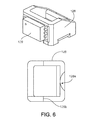
- FIG. 6 is a bottom perspective view and side perspective view of an exemplary hall sensor of FIG. 3 .
- FIG. 7 is a top perspective view and side perspective view of an exemplary hall sensor in bump design.
- FIG. 8 is a top perspective view and side perspective view of an exemplary hall sensor in via design.
- FIG. 9 is a top perspective view and side perspective view of an exemplary hall sensor in pocket design.
- FIG. 10 is an illustration of an alternative embodiment of a sensor mount.
- FIG. 11 is a top view of a rigid-flex PCB of the sensor mount of FIG. 10 .
- FIG. 12 illustrates a break-away tab of the rigid-flex PCT of FIG. 11 .
- This description relates to mounting a Hall sensor in an implantable blood pump.
- a molded interconnect device may allow a Hall sensor to be positioned at an adequate position within the blood pump, while the device may be inserted into the pump with insertion machines employed for the assembly of the pump.
- the implementations or aspects described herein allow a Hall sensor to be positioned and mounted on a printed circuit board of a stator of the pump thereby allowing the Hall sensor to transduce a position of a rotor during operation of the pump.
- mechanical stress on integrated electronic conductive traces of the molded interconnect device may be reduced and may thereby enhance the robustness of a connection between the device and a printed circuit board.
- particular aspects described herein may provide improved robustness of the device carrying the Hall sensor on the board and within the pump, e.g. for halt or break off test of the motor of the pump.
- the molded interconnect device carrying the Hall sensor may allow adhesives to be easily employed to further enhance the stability of the Hall sensor in the pump.
- the force applied to a soldered joint between the printed circuit board and the molded interconnect device during operation of the pump may be reduced, e.g. the force may a centrifugal force, a shear force and/or a frictional force.
- a left ventricular assist blood pump 100 having a puck-shaped housing 110 is implanted in a patient's body with a first face 111 of the housing 110 positioned against the patient's heart H and a second face 113 of the housing 110 facing away from the heart H.
- the first face 111 of the housing 110 includes an inlet cannula 112 extending into the left ventricle LV of the heart H.
- the second face 113 of the housing 110 has a chamfered edge 114 to avoid irritating other tissue that may come into contact with the blood pump 100 , such as the patient's diaphragm.
- a stator 120 and electronics 130 of the pump 100 are positioned on the inflow side of the housing toward first face 111 , and a rotor 140 of the pump 100 is positioned along the second face 113 .
- This positioning of the stator 120 , electronics 130 , and rotor 140 permits the edge 114 to be chamfered along the contour of the rotor 140 , as illustrated in at least FIGS. 2, 4, and 5 , for example.
- the blood pump 100 includes a dividing wall 115 within the housing 110 defining a blood flow conduit 103 .
- the blood flow conduit 103 extends from an inlet opening 101 of the inlet cannula 112 through the stator 120 to an outlet opening 105 defined by the housing 110 .
- the rotor 140 is positioned within the blood flow conduit 103 .
- the stator 120 is disposed circumferentially about a first portion 140 a of the rotor 140 , for example about a permanent magnet 141 .
- the stator 120 is also positioned relative to the rotor 140 such that, in use, blood flows within the blood flow conduit 103 through the stator 120 before reaching the rotor 140 .
- the permanent magnet 141 has a permanent magnetic north pole N and a permanent magnetic south pole S for combined active and passive magnetic levitation of the rotor 140 and for rotation of the rotor 140 .
- the rotor 140 also has a second portion 140 b that includes impeller blades 143 .
- the impeller blades 143 are located within a volute 107 of the blood flow conduit such that the impeller blades 143 are located proximate to the second face 113 of the housing 110 .
- the puck-shaped housing 110 further includes a peripheral wall 116 that extends between the first face 111 and a removable cap 118 .
- the peripheral wall 116 is formed as a hollow circular cylinder having a width W between opposing portions of the peripheral wall 116 .
- the housing 110 also has a thickness T between the first face 111 and the second face 113 that is less than the width W.
- the thickness T is from about 0.5 inches to about 1.5 inches, and the width W is from about 1 inch to about 4 inches.
- the width W can be approximately 2 inches, and the thickness T can be approximately 1 inch.
- the peripheral wall 116 encloses an internal compartment 117 that surrounds the dividing wall 115 and the blood flow conduit 103 , with the stator 120 and the electronics 130 disposed in the internal compartment 117 about the dividing wall 115 .
- the removable cap 118 includes the second face 113 , the chamfered edge 114 , and defines the outlet opening 105 .
- the cap 118 can be threadedly engaged with the peripheral wall 116 to seal the cap 118 in engagement with the peripheral wall 116 .
- the cap 118 includes an inner surface 118 a of the cap 118 that defines the volute 107 that is in fluid communication with the outlet opening 105 .
- the electronics 130 are positioned adjacent to the first face 111 and the stator 120 is positioned adjacent to the electronics 130 on an opposite side of the electronics 130 from the first face 111 .
- the electronics 130 include circuit boards 131 and various components 133 carried on the circuit boards 131 to control the operation of the pump 100 by controlling the electrical supply to the stator 120 .
- the housing 110 is configured to receive the circuit boards 131 within the internal compartment 117 generally parallel to the first face 111 for efficient use of the space within the internal compartment 117 .
- the circuit boards also extend radially-inward towards the dividing wall 115 and radially-outward towards the peripheral wall 116 .
- the internal compartment 117 is generally sized no larger than necessary to accommodate the circuit boards 131 , and space for heat dissipation, material expansion, potting materials, and/or other elements used in installing the circuit boards 131 .
- the external shape of the housing 110 proximate the first face 111 generally fits the shape of the circuits boards 131 closely to provide external dimensions that are not much greater than the dimensions of the circuit boards 131 .
- the stator 120 includes a back iron 121 and pole pieces 123 a - 123 f arranged at intervals around the dividing wall 115 .
- the back iron 121 extends around the dividing wall 115 and is formed as a generally flat disc of a ferromagnetic material, such as steel, in order to conduct magnetic flux.
- the back iron 121 is arranged beside the control electronics 130 and provides a base for the pole pieces 123 a - 123 f.
- Each of the pole piece 123 a - 123 f is L-shaped and has a drive coil 125 for generating an electromagnetic field to rotate the rotor 140 .
- the pole piece 123 a has a first leg 124 a that contacts the back iron 121 and extends from the back iron 121 towards the second face 113 .
- the pole piece 123 a may also have a second leg 124 b that extends from the first leg 124 a through an opening 132 of a printed circuit board 131 towards the dividing wall 115 proximate the location of the permanent magnet 141 of the rotor 140 .
- each of the second legs 124 b of the pole pieces 123 a - 123 f is sticking through an opening 132 of the printed circuit board 131 .
- each of the first legs 124 a of the pole pieces 123 a - 123 f is sticking through an opening 132 of the printed circuit board 131 .
- the openings 132 of the printed circuit board are enclosing the first legs 124 a of the pole pieces 123 a - 123 f.
- At least one molded interconnect device 128 is mounted on the printed circuit board of the pump 100 , e.g. the at least one molded interconnect device 128 is mounted on the printed circuit board of the stator 120 .
- the molded interconnect device 128 comprises a Hall sensor 129 , e.g., the molded interconnect device 128 carries the Hall sensor 129 .
- the molded interconnect device 128 may be mounted on the printed circuit board 131 via one or more of integrated electric circuit traces, soldered joint and adhesive.
- the molded interconnect device 128 may be mounted to the printed circuit board 131 using an epoxy or liquid polymer crystals as the adhesive.
- the molded interconnect device 128 may be glued to the printed circuit board 131 .
- the epoxy is a rapid curing, fast flowing, liquid epoxy for use as capillary flow underfill on printed circuit boards, wherein when the epoxy is fully cured, it may reduce (e.g., minimize) induced stress at solder joints between the printed circuit board 131 and the molded interconnect device 128 .
- the adhesive may improve a thermal cycling performance of the printed circuit board 131 , the molded interconnect device 128 and/or the soldered joints.
- the adhesive provides the functionality of an underfill between the printed circuit board 131 and the at least one molded interconnect device 128 .
- the adhesive may be applied (e.g., as underfill) between the Hall sensor 129 and the printed circuit board 131 and/or between the printed circuit board 131 and the molded interconnect device 128 .
- the Hall sensor 129 may be configured to transduce a position of the rotor 140 of the pump 100 .
- the Hall sensor may be in upright position on the printed circuit board 131 .
- the Hall sensor may be standing orthogonally on the printed circuit board 131 .
- a longest edge of the Hall sensor may be aligned to possess an orthogonal component with respect to the surface of the printed circuit board 131 .
- the Hall sensor 129 may be adapted to sense a position of the rotor 140 of the pump 100 .
- the Hall sensor 129 may provide an output voltage, which is directly proportional to a strength of a magnetic field that is located in between at least one of the pole pieces 123 a - 123 f and the permanent magnet 141 .
- the Hall sensor 129 may provide an output voltage, which is directly proportional to a strength of a magnetic field that is located in a proximity of at least one of the pole pieces 123 a - 123 f and the rotor 140 of the pump 100 .
- the Hall sensor 129 may provide an output voltage, which is directly proportional to a strength of a magnetic field that is located in between at least one of the pole pieces 123 a - 123 f and the permanent magnet 141 , and wherein the output voltage is directly proportional to a current flowing in the Hall sensor 129 .
- the Hall sensor 129 may provide an output voltage, which is directly proportional to a strength of a magnetic field that is located in between at least one of the pole pieces 123 a - 123 f and the permanent magnet 141 , and the output voltage may provide feedback to the control electronics 130 of the pump 100 to determine if the rotor 140 and/or the permanent magnet 141 is not at its intended position for the operation of the pump 100 .
- a position of the rotor 140 and/or the permanent magnet 141 may be adjusted, e.g. the rotor 140 or the permanent magnet 141 may be pushed or pulled towards a center of the blood flow conduit 103 or towards a center of the stator 120 .
- Each of the pole pieces 123 a - 123 f also has a levitation coil 127 for generating an electromagnetic field to control the radial position of the rotor 140 .
- Each of the drive coils 125 and the levitation coils 127 includes multiple windings of a conductor around the pole pieces 123 a - 123 f .
- each of the drive coils 125 is wound around two adjacent ones of the pole pieces 123 , such as pole pieces 123 d and 123 e , and each levitation coil 127 is wound around a single pole piece.
- the drive coils 125 and the levitation coils 127 are wound around the first legs of the pole pieces 123 , and magnetic flux generated by passing electrical current though the coils 125 and 127 during use is conducted through the first legs and the second legs of the pole pieces 123 and the back iron 121 .
- the drive coils 125 and the levitation coils 127 of the stator 120 are arranged in opposing pairs and are controlled to drive the rotor and to radially levitate the rotor 140 by generating electromagnetic fields that interact with the permanent magnetic poles S and N of the permanent magnet 141 .
- stator 120 includes both the drive coils 125 and the levitation coils 127 , only a single stator is needed to levitate the rotor 140 using only passive and active magnetic forces.
- the permanent magnet 141 in this configuration has only one magnetic moment and is formed from a monolithic permanent magnetic body 141 .
- the stator 120 can be controlled as discussed in U.S. Pat. No. 6,351,048, the entire contents of which are incorporated herein for all purposes by reference.
- the control electronics 130 and the stator 120 receive electrical power from a remote power supply via a cable 119 ( FIG. 1 ). Further related patents, namely U.S. Pat. No. 5,708,346, U.S. Pat. No. 6,053,705, U.S. Pat. No.
- the rotor 140 is arranged within the housing 110 such that its permanent magnet 141 is located upstream of impeller blades in a location closer to the inlet opening 101 .
- the permanent magnet 141 is received within the blood flow conduit 103 proximate the second legs 124 b of the pole pieces 123 to provide the passive axial centering force though interaction of the permanent magnet 141 and ferromagnetic material of the pole pieces 123 .
- the permanent magnet 141 of the rotor 140 and the dividing wall 115 form a gap 108 between the permanent magnet 141 and the dividing wall 115 when the rotor 140 is centered within the dividing wall 115 .
- the gap 108 may be from about 0.2 millimeters to about 2 millimeters.
- the gap 108 is approximately 1 millimeter.
- the north permanent magnetic pole N and the south permanent magnetic pole S of the permanent magnet 141 provide a permanent magnetic attractive force between the rotor 140 and the stator 120 that acts as a passive axial centering force that tends to maintain the rotor 140 generally centered within the stator 120 and tends to resist the rotor 140 from moving towards the first face 111 or towards the second face 113 .
- the rotor 140 also includes a shroud 145 that covers the ends of the impeller blades 143 facing the second face 113 that assists in directing blood flow into the volute 107 .
- the shroud 145 and the inner surface 118 a of the cap 118 form a gap 109 between the shroud 145 and the inner surface 118 a when the rotor 140 is levitated by the stator 120 .
- the gap 109 is from about 0.2 millimeters to about 2 millimeters. For example, the gap 109 is approximately 1 millimeter.
- the exemplary gaps 108 and 109 are large enough to allow adequate blood flow to limit clot formation that may occur if the blood is allowed to become stagnant.
- the gaps 108 and 109 are also large enough to limit pressure forces on the blood cells such that the blood is not damaged when flowing through the pump 100 .
- the gaps 108 and 109 are too large to provide a meaningful hydrodynamic suspension effect. That is to say, the blood does not act as a bearing within the exemplary gaps 108 and 109 , and the rotor is only magnetically-levitated.
- the gaps 108 and 109 are sized and dimensioned so the blood flowing through the gaps forms a film that provides a hydrodynamic suspension effect. In this manner, the rotor can be suspended by magnetic forces, hydrodynamic forces, or both.
- the exemplary rotor 140 is radially suspended by active control of the levitation coils 127 as discussed above, and because the rotor 140 is axially suspended by passive interaction of the permanent magnet 141 and the stator 120 , no rotor levitation components are needed proximate the second face 113 .
- the incorporation of all the components for rotor levitation in the stator 120 i.e., the levitation coils 127 and the pole pieces 123 ) allows the cap 118 to be contoured to the shape of the impeller blades 143 and the volute 107 . Additionally, incorporation of all the rotor levitation components in the stator 120 eliminates the need for electrical connectors extending from the compartment 117 to the cap 118 , which allows the cap to be easily installed and/or removed and eliminates potential sources of pump failure.
- the drive coils 125 of the stator 120 generates electromagnetic fields through the pole pieces 123 that selectively attract and repel the magnetic north pole N and the magnetic south pole S of the rotor 140 to cause the rotor 140 to rotate within stator 120 .
- the Hall sensor 129 may sense a current position of the rotor 140 and/or the permanent magnet 141 , wherein the output voltage of the Hall sensor 129 may be used to selectively attract and repel the magnetic north pole N and the magnetic south pole S of the rotor 140 to cause the rotor 140 to rotate within stator 120 .
- the impeller blades 143 force blood into the volute 107 such that blood is forced out of the outlet opening 105 .
- the rotor draws blood into pump 100 through the inlet opening 101 .
- the blood flows through the inlet opening 101 and flows through the control electronics 130 and the stator 120 toward the rotor 140 .
- Blood flows through the aperture 141 a of the permanent magnet 141 and between the impeller blades 143 , the shroud 145 , and the permanent magnet 141 , and into the volute 107 .
- Blood also flows around the rotor 140 , through the gap 108 and through the gap 109 between the shroud 145 and the inner surface 118 a of the cap 118 .
- the blood exits the volute 107 through the outlet opening 105 .
- FIG. 6 describes a bottom and side view of an exemplary molded interconnect device 128 according to an aspect described herein.
- the molded interconnect device 128 may carry the Hall sensor 129 on one surface of the molded interconnect device 128 , wherein the Hall sensor may be electrically connected with the molded interconnect device 128 via one or more integrated electronic circuit traces 133 .
- the Hall sensor 129 may be located inside the device 128 or may be partially enclosed by the device 128 .
- the bottom of the molded interconnect device 128 is facing the bottom side of the pump 100 .
- the top of the molded interconnect device 128 is facing the printed circuit board 131 of the pump 100 .
- the bottom perspective of the molded interconnect device is illustrated in FIG. 6 (lower illustration).
- the molded interconnect device 128 may possess a cut-out 128 a , wherein film gate material may be removed.
- a thickness 128 b of walls of the molded interconnect device 128 may be adapted for the molded interconnect device 128 to be aligned on the printed circuit board 131 with an automated assembly machine, wherein the automated assembly machine may also be used to assemble the printed circuit board 131 and/or the stator 120 of the pump 100 .
- the thickness 128 b may be below 1 millimeter, preferentially about 0.7 millimeters.
- An adhesive e.g. an underfill material
- This particular aspect or implementation may limit force flow through the integrated circuit traces and rather leads the forces directly through the adhesive into the printed circuit board 131 .
- the adhesive may be easily implemented with the printed circuit board assembly and manufacturing process.
- the molded interconnect device 128 may be designed with recesses (e.g., pockets) that enable a form fit between the molded interconnect device 128 and soldered joints of the printed circuit board 131 .
- laser parameters for structuring the molded interconnect device 128 may be optimized and a width of the integrated electronic circuit traces may be increased.
- mechanical forces may be generated due to thermal expansion and metallized traces or joints may become separated from their supporting material, wherein the metallized traces may experience a fracture during pump operation.
- halt tests and/or break off tests of the motor were performed and rendered one or more of the following designs of the molded interconnect device 128 particularly mechanically robust during operation of the pump.
- FIG. 7 describes an exemplary top and side view of a hall sensor in a bump design according to one or more aspects of the present disclosure.
- the molded interconnect device 128 carries a Hall sensor 129 and includes multiple integrated electronic circuit traces 133 , wherein one or more bumps 132 may be added to the traces 133 .
- This particular aspect may reduce mechanical stress on the traces 133 , e.g., by using a mechanical form fit.
- the size of the bump 132 may be below 1 millimeters, preferentially be 0.73 millimeters.
- the molded interconnect device 128 may include four bumps that are located at each corner of one surface of the device 128 , wherein the surface is facing the printed circuit board 131 when the device 128 is mounted on the printed circuit board 131 .
- FIG. 8 describes an exemplary top and side view of a Hall sensor in a via design according to one or more aspects of the present disclosure.
- the molded interconnect device 128 carries a Hall sensor 129 and includes one or more integrated electronic circuit traces 133 , wherein one or more electrically conductive pins 134 may each include at least one via 134 a .
- the pins 134 may be a part of the traces 133 .
- This particular implementation may increase a strength of the connection between the traces 133 and the molded interconnect device 128 by implementing the via 134 a that may extend through a wall of the device 128 .
- the via 134 a is a hole or a hollow channel extending through the wall of the molded interconnect device 128 .
- the pins 134 may be soldered to the printed circuit board 131 thereby electrically connecting the Hall sensor 129 with the board 131 .
- FIG. 9 describes an exemplary top and side view of a Hall sensor in a pocket design according to one or more aspects of the present disclosure.
- the molded interconnect device 128 carries a Hall sensor 129 and includes one or more integrated electronic circuit traces 133 , wherein one or more electrically conductive recesses 135 or pockets 135 may be located at one or more surfaces of the device 128 .
- the recess or pocket 135 may be an electrically conductive pin that is formed by a cut-out of a wall of the device 128 .
- the recess or pocket 135 may be formed by cutting-out a fraction of a wall of the molded interconnect device 128 .
- the fraction may be cut out at a corner of the device 128 , wherein the corner is facing the printed circuit board 131 when the device 128 is mounted on the board 131 .
- the width 135 b of the recess 135 may be less than 1 millimeter, preferentially 0.6 millimeter.
- the length 135 a of the recess 135 may be less than 1 millimeter, preferentially 0.8 millimeter.
- the height of the recess 135 may be less than 1 millimeter.
- the molded interconnect device is wedge- or trapeze-shaped with an apex angle 128 c between 10 and 45 degrees, preferentially 25 degrees or 30 degrees.
- the recess or pocket 135 may be form-fit with soldered joints, the soldered joints electrically and/or mechanically connecting the printed circuit board 131 with the integrated electronic circuit traces 133 of the molded interconnect device 128 .
- each recess or pocket 135 of the device 128 may at least partially enclose a soldered joint, the soldered joints electrically and/or mechanically connecting the printed circuit board 131 with the integrated electronic circuit traces 133 of the molded interconnect device 128 .
- the recess or pocket 135 may be at least partially filled with an adhesive, which mounts the device 128 to the printed circuit board 131 and secures mounting of the molded interconnect device 128 to the printed circuit board 131 of the pump 100 during operation of the pump 100 .
- the adhesive e.g., a liquid epoxy
- the particular implementation described herein may remove forces applied to the traces 133 and/or the soldered joints during operation of the pump 100 and may guide these forces between the device 128 and the board 131 through the adhesive (e.g. underfill), wherein the forces may for example be centrifugal forces, shear forces and/or frictional forces.
- the particular implementation of the pocket design described in the context of FIG. 9 may reduce mechanical stress on the traces 133 of the molded interconnect device 128 and may thereby enhance the robustness of a connection between the device 128 and the board 131 .
- the particular implementation of the pocket design described herein may increase the stability of the integrated electronic circuit traces 133 of the molded interconnect device 128 .
- the particular implementation of the pocket design described herein may increase the stability of the connection between the integrated electronic circuit traces 133 and the molded interconnect device 128 .
- the particular implementation of the pocket design described herein may reduce the force applied to the integrated electronic circuit traces 133 of the molded interconnect device 128 , e.g.
- the force may a centrifugal force, a shear force and/or a frictional force that may occur during operation of the implantable blood pump 100 .
- the particular implementation of the pocket design described in the context of FIG. 9 may reduce the force applied to the soldered joint between the printed circuit board 131 and the molded interconnect device 128 , e.g. the force may a centrifugal force, a shear force and/or a frictional force that may occur during operation of the implantable blood pump 100 .
- the particular implementations or aspects described in FIGS. 7, 8 and 9 may provide improved robustness of the device 128 on the board 131 within the pump 100 , e.g. the robustness may be determined or classified by a halt or break off test of the motor of the pump 100 .
- using silicone coating in a proximity of the molded interconnect device 128 on the printed circuit board 131 may be a buffer and may reduce mechanical stress on the device 128 and/or the Hall sensor 129 .
- the width of the integrated electronic circuit traces 133 may be 0.2-0.25 millimeters.
- lead-free solder may be applied between the Hall sensor 129 and the molded interconnect device 128 .
- the molded interconnect device 128 is directly soldered on the printed circuit board 131 of the pump 100 .
- a printed circuit board 202 having rigid 204 and flexible 206 portions provides mechanical compliance between the individual sensors 208 while maintaining a single set of soldered electrical interconnects between the sensor and the remainder of the system.
- mechanical positioning tolerances in the mechanical fixturing can be accommodated without placing excessive stress on the electrical interconnectors.
- Eight axi-symmetric sensors 208 are placed in a rigid, plastic mechanical carrier 210 and the Rigid-Flex PCB 202 is placed onto the carrier.
- the mechanical carrier uses guide rails 212 to locate electrically neutral rigid PCB portions 214 attached to the top edges of the sensors 208 and to locate the Rigid-Flex PCB 202 . Excess rigid break-away tabs 216 of the rigid-flex PCB 202 (shown in FIG. 11 ) have been removed in FIG. 10 .
- the electrically neutral rigid PCB portions 214 are attached to their top edges.
- This rigid PCB portion allows the person or robot assembling the sensor unit to grab the rigid PCB supporting each sensor without causing mechanical damage to the sensor itself.
- this neutral portion of rigid PCB can be masked with a static dissipative coating that minimizes the change of electrostatic discharge (ESD) damage to the sensor IC.
- ESD electrostatic discharge
- the excess portion 216 of the rigid PCB is broken off by the assembler, leaving a minimum amount of rigid PCB to support the sensor and allowing an overall smaller assembly.
- the excess rigid PCB 216 is removed through the use of carefully positioned “break-away” scoring marks 218 and/or small holes 219 commonly called “mouse bites”.
- the cap 118 can be engaged with the peripheral wall 116 using a different attachment mechanism or technique, including snap-fit engagement, adhesives, or welding.
- the cap 118 has been described as defining the outlet opening 105 and the chamfered edge 114
- the outlet opening 105 and/or the chamfered edge 114 can be defined by the peripheral wall 116 or by both the peripheral wall 116 and the cap 118 .
- the dividing wall 115 can be formed as part of the cap 118 .
- the rotor 140 can include two or more permanent magnets.
- the number and configuration of the pole pieces 123 can also be varied.
- the operation of the control electronics 130 is selected to account for the number and position of pole pieces of the stator and permanent magnets of the rotor.
- the cap 118 can be engaged with the peripheral wall using other techniques, such as adhesives, welding, snap-fit, shrink-fit, or other technique or structure.
- the first face 111 may be formed from a separate piece of material than the peripheral wall 116 and the first face 111 , including the inlet cannula 112 , can be attached to the peripheral wall 116 , such as by welding, after the control electronics 130 and the stator 120 have been mounted in the internal compartment 117 .
- the shroud 145 may be omitted and optionally replaced by other flow control devices to achieve a desired pump efficiency.
- the control electronics 130 can be located external to the pump 100 , such as in a separate housing implanted in the patient's abdomen, or external to the patient's body.
- the dimensions of the housing 110 can be larger or smaller than those described above.
- the ratio of the width W of the housing 110 to the thickness T of the housing can be different than the ratio described above.
- the width W can be from about 1.1 to about 5 times greater than the thickness T.
- the permanent magnet 141 of the rotor 140 can include two or more pairs of north and south magnetic poles. While the peripheral wall 116 and the dividing wall 115 are illustrated as cylinders having circular cross-sectional shapes, one or both can alternatively be formed having other cross-sectional shapes, such as oval, or an irregular shape. Similarly, the peripheral wall 116 can be tapered such that the housing does not have a constant width W from the first face 111 to the second face 113 .
- the blood pump 100 can be used to assist a patient's heart during a transition period, such as during a recovery from illness and/or surgery or other treatment.
- the blood pump 100 can be used to partially or completely replace the function of the patient's heart on a generally permanent basis.
- the molded interconnect device 128 carrying the Hall sensor 129 may allow to monitor the position of the rotor of the pump 100 and may thereby help to ensure a proper operating status of the implantable blood pump 100 .
- example Hall sensor 129 or molded interconnect device 128 contemplates using, implementing, or executing any suitable technique for performing these and other tasks. It will be understood that these processes and parts are for illustration purposes only and that the described or similar techniques may be performed at any appropriate time, including concurrently, individually, in parallel, and/or in combination. In addition, many of the steps or parts in these processes may take place simultaneously, concurrently, in parallel, and/or in different orders than as shown. Moreover, molded interconnect device 128 may use components with additional parts, fewer parts, and/or different parts, so long as the devices remain appropriate.
Abstract
Description
Claims (18)
Priority Applications (2)
| Application Number | Priority Date | Filing Date | Title |
|---|---|---|---|
| US14/015,542 US9492599B2 (en) | 2012-08-31 | 2013-08-30 | Hall sensor mounting in an implantable blood pump |
| US15/286,449 US10413650B2 (en) | 2012-08-31 | 2016-10-05 | Hall sensor mounting in an implantable blood pump |
Applications Claiming Priority (2)
| Application Number | Priority Date | Filing Date | Title |
|---|---|---|---|
| US201261695624P | 2012-08-31 | 2012-08-31 | |
| US14/015,542 US9492599B2 (en) | 2012-08-31 | 2013-08-30 | Hall sensor mounting in an implantable blood pump |
Related Child Applications (1)
| Application Number | Title | Priority Date | Filing Date |
|---|---|---|---|
| US15/286,449 Continuation US10413650B2 (en) | 2012-08-31 | 2016-10-05 | Hall sensor mounting in an implantable blood pump |
Publications (2)
| Publication Number | Publication Date |
|---|---|
| US20140067056A1 US20140067056A1 (en) | 2014-03-06 |
| US9492599B2 true US9492599B2 (en) | 2016-11-15 |
Family
ID=50184424
Family Applications (4)
| Application Number | Title | Priority Date | Filing Date |
|---|---|---|---|
| US14/015,542 Active 2034-01-05 US9492599B2 (en) | 2012-08-31 | 2013-08-30 | Hall sensor mounting in an implantable blood pump |
| US14/015,630 Active 2035-07-11 US9579436B2 (en) | 2012-08-31 | 2013-08-30 | Sensor mounting in an implantable blood pump |
| US15/286,449 Active 2033-12-21 US10413650B2 (en) | 2012-08-31 | 2016-10-05 | Hall sensor mounting in an implantable blood pump |
| US15/408,136 Active 2034-09-04 US10485911B2 (en) | 2012-08-31 | 2017-01-17 | Sensor mounting in an implantable blood pump |
Family Applications After (3)
| Application Number | Title | Priority Date | Filing Date |
|---|---|---|---|
| US14/015,630 Active 2035-07-11 US9579436B2 (en) | 2012-08-31 | 2013-08-30 | Sensor mounting in an implantable blood pump |
| US15/286,449 Active 2033-12-21 US10413650B2 (en) | 2012-08-31 | 2016-10-05 | Hall sensor mounting in an implantable blood pump |
| US15/408,136 Active 2034-09-04 US10485911B2 (en) | 2012-08-31 | 2017-01-17 | Sensor mounting in an implantable blood pump |
Country Status (3)
| Country | Link |
|---|---|
| US (4) | US9492599B2 (en) |
| EP (1) | EP2890417A4 (en) |
| WO (1) | WO2014036419A1 (en) |
Cited By (5)
| Publication number | Priority date | Publication date | Assignee | Title |
|---|---|---|---|---|
| US20170016449A1 (en) * | 2015-07-14 | 2017-01-19 | Hamilton Sundstrand Corporation | Axial-flux induction motor pump |
| US9551379B1 (en) * | 2016-01-15 | 2017-01-24 | Matteo B. Gravina | Thermal efficiency heat rate improvement over power generation and emissions control |
| US10485911B2 (en) | 2012-08-31 | 2019-11-26 | Tc1 Llc | Sensor mounting in an implantable blood pump |
| US10947986B2 (en) * | 2018-07-11 | 2021-03-16 | Ch Biomedical (Usa) Inc. | Compact centrifugal pump with magnetically suspended impeller |
| US20210205600A1 (en) * | 2018-01-10 | 2021-07-08 | Tc1 Llc | Bearingless Implantable Blood Pump |
Families Citing this family (17)
| Publication number | Priority date | Publication date | Assignee | Title |
|---|---|---|---|---|
| EP2564771A1 (en) | 2011-09-05 | 2013-03-06 | ECP Entwicklungsgesellschaft mbH | Medicinal product with a functional element for invasive use in the body of a patient |
| JP6446212B2 (en) * | 2014-09-12 | 2018-12-26 | 泉工医科工業株式会社 | Drive device for centrifugal blood pump |
| AU2014409584B2 (en) | 2014-10-22 | 2017-12-21 | Halliburton Energy Services, Inc. | Mounting plate apparatus, systems, and methods |
| US10236742B2 (en) | 2014-11-25 | 2019-03-19 | Black & Decker Inc. | Brushless motor for a power tool |
| GB2541031B (en) * | 2015-08-07 | 2017-09-06 | Magpumps Ltd | Gear pump for pumping fluid |
| US11624362B2 (en) | 2015-08-07 | 2023-04-11 | Magpumps Limited | Device for pumping fluid |
| US10500708B2 (en) | 2015-10-14 | 2019-12-10 | Black & Decker Inc. | Power tool |
| US10292268B2 (en) * | 2015-12-24 | 2019-05-14 | Htc Corporation | Flexible printed circuit board, supporting holder and controller |
| CN106922079B (en) * | 2015-12-24 | 2019-07-05 | 宏达国际电子股份有限公司 | Flexible circuit board, bearing seat and controller |
| EP3634528B1 (en) | 2017-06-07 | 2023-06-07 | Shifamed Holdings, LLC | Intravascular fluid movement devices, systems, and methods of use |
| DE102017122804A1 (en) * | 2017-09-29 | 2019-04-04 | Fresenius Medical Care Deutschland Gmbh | Medical pump drive, pump and blood treatment device |
| EP3710076B1 (en) | 2017-11-13 | 2023-12-27 | Shifamed Holdings, LLC | Intravascular fluid movement devices, systems, and methods of use |
| EP3746149A4 (en) | 2018-02-01 | 2021-10-27 | Shifamed Holdings, LLC | Intravascular blood pumps and methods of use and manufacture |
| US10838023B2 (en) * | 2019-01-25 | 2020-11-17 | Aktiebolaget Skf | High performance magnetic ring and sensor arrangement |
| US11654275B2 (en) | 2019-07-22 | 2023-05-23 | Shifamed Holdings, Llc | Intravascular blood pumps with struts and methods of use and manufacture |
| WO2021062265A1 (en) | 2019-09-25 | 2021-04-01 | Shifamed Holdings, Llc | Intravascular blood pump systems and methods of use and control thereof |
| EP4006351A1 (en) * | 2020-11-26 | 2022-06-01 | Wilo Se | Centrifugal pump with a motor |
Citations (174)
| Publication number | Priority date | Publication date | Assignee | Title |
|---|---|---|---|---|
| US845816A (en) | 1902-03-05 | 1907-03-05 | Charles H Tompkins | Centripetal-centrifugal pump and condenser. |
| US888654A (en) | 1902-03-05 | 1908-05-26 | Charles H Tompkins | Means for transmitting power. |
| US1026101A (en) | 1910-12-23 | 1912-05-14 | Elon A Marsh | Centrifugal pump. |
| US2128988A (en) | 1937-04-02 | 1938-09-06 | Christian John Russell | Game board |
| US2747512A (en) | 1951-05-24 | 1956-05-29 | Fouche Rene Paul | Motor pump |
| US2864552A (en) | 1954-08-18 | 1958-12-16 | Sir George Godfrey & Partners | Shaft or like bearings |
| US3005117A (en) | 1959-03-20 | 1961-10-17 | Gen Electric | Electro-mechanical device |
| US3066849A (en) | 1960-08-18 | 1962-12-04 | Exemplar Inc | High vacuum pump systems |
| US3122101A (en) | 1960-09-22 | 1964-02-25 | North American Aviation Inc | Bearingless pump |
| US3225608A (en) | 1962-11-27 | 1965-12-28 | Gen Motors Corp | Diamagnetic suspension system |
| US3401640A (en) | 1965-12-03 | 1968-09-17 | Newage Lyon Ltd | Centrifugal pumps |
| US3499274A (en) | 1967-08-25 | 1970-03-10 | Rector C Fergason | Cotton harvester |
| US3575536A (en) | 1969-02-07 | 1971-04-20 | Jet Spray Cooler Inc | Pump for beverage dispenser |
| US3597022A (en) | 1969-07-22 | 1971-08-03 | Robert D Waldron | Diamagnetic levitation and/or stabilizing devices |
| US3608088A (en) | 1969-04-17 | 1971-09-28 | Univ Minnesota | Implantable blood pump |
| US3611815A (en) | 1969-12-24 | 1971-10-12 | Us Navy | Frictionless gyroscope |
| US3647324A (en) | 1969-12-18 | 1972-03-07 | Edson Howard Rafferty | Electrically driven pumps capable of use as heart pumps |
| US3650581A (en) | 1969-06-30 | 1972-03-21 | Karl Boden Wilhelm Groth & Die | Bearing systems |
| US3938913A (en) | 1971-12-20 | 1976-02-17 | Maschinenfabrik Augsburg-Nurnberg Aktiengesellschaft | Flow machine for an aggressive, radioactive or special-purity flow medium |
| US3957389A (en) | 1967-10-26 | 1976-05-18 | Bio-Medicus, Inc. | Pumping apparatus and process characterized by gentle operation |
| GB1491710A (en) | 1974-08-15 | 1977-11-16 | Howarth A | Induction machines |
| US4082376A (en) | 1974-12-06 | 1978-04-04 | Arthur Pfeiffer Vakuumtechnik Wetzlar Gmbh | Bearing arrangement |
| US4135253A (en) | 1976-11-30 | 1979-01-23 | Medtronic, Inc. | Centrifugal blood pump for cardiac assist |
| US4167296A (en) | 1977-12-30 | 1979-09-11 | Sperry Rand Corporation | Protective control system for magnetic suspension and magnetically suspended devices |
| US4213207A (en) | 1978-04-07 | 1980-07-22 | Wilson Frederick M | Artificial heart and method of pumping blood |
| US4340260A (en) | 1979-09-25 | 1982-07-20 | Siemens Aktiengesellschaft | Magnetic suspension bearing |
| US4382199A (en) | 1980-11-06 | 1983-05-03 | Nu-Tech Industries, Inc. | Hydrodynamic bearing system for a brushless DC motor |
| US4398773A (en) | 1979-05-12 | 1983-08-16 | Kernforschungsanlage Julich Gesellschaft Mit Beschrankter Haftung | Magnetic suspension assembly for a rotor |
| US4405286A (en) | 1982-01-21 | 1983-09-20 | The United States Of America As Represented By The Administrator Of The National Aeronautics And Space Administration | Actively suspended counter-rotating machine |
| US4408966A (en) | 1979-12-27 | 1983-10-11 | Matsushita Electric Industrial Co., Ltd. | Pump for supplying liquid fuel |
| US4475866A (en) | 1981-04-30 | 1984-10-09 | Doryokuro Kakunenryo Kaihatsu Jigyodan | Liquid metal mechanical pump |
| US4507048A (en) | 1979-03-16 | 1985-03-26 | Jacques Belenger | Centrifugal clinical blood pump |
| US4547039A (en) | 1982-04-16 | 1985-10-15 | Amp Incorporated | Housing mountable on printed circuit board to interconnect fiber optic connectors |
| US4589822A (en) | 1984-07-09 | 1986-05-20 | Mici Limited Partnership Iv | Centrifugal blood pump with impeller |
| US4642036A (en) | 1984-09-17 | 1987-02-10 | Young Niels O | Magnet ball pump |
| US4688998A (en) | 1981-03-18 | 1987-08-25 | Olsen Don B | Magnetically suspended and rotated impellor pump apparatus and method |
| US4704121A (en) | 1983-09-28 | 1987-11-03 | Nimbus, Inc. | Anti-thrombogenic blood pump |
| US4763032A (en) | 1983-11-29 | 1988-08-09 | Fraunhofer-Gesellschaft Zur Forderung Der Angewandten Forschung E.V. | Magnetic rotor bearing |
| US4779614A (en) | 1987-04-09 | 1988-10-25 | Nimbus Medical, Inc. | Magnetically suspended rotor axial flow blood pump |
| US4844707A (en) | 1987-06-12 | 1989-07-04 | Kletschka Harold D | Rotary pump |
| US4876492A (en) | 1988-02-26 | 1989-10-24 | General Electric Company | Electronically commutated motor driven apparatus including an impeller in a housing driven by a stator on the housing |
| US4878831A (en) | 1988-10-24 | 1989-11-07 | Forney International, Inc. | Infrared flame detector adaptable for different fuels |
| US4898759A (en) | 1988-07-27 | 1990-02-06 | Nidec Corporation | Molded printed circuit board for use with a brushless electric motor |
| US4922199A (en) * | 1988-05-27 | 1990-05-01 | Enprotech Corp. | Rotary position transducer having hinged circuit boards |
| US4929158A (en) | 1987-04-09 | 1990-05-29 | Societe Europeenne De Propulsion | Turbopump with actine suspension for a propulsion system |
| EP0378251A2 (en) | 1981-03-18 | 1990-07-18 | Günther Walter Otto Bramm | Magnetically suspended and rotated impellor pump apparatus |
| US4944748A (en) | 1986-10-12 | 1990-07-31 | Bramm Gunter W | Magnetically suspended and rotated rotor |
| US4957504A (en) | 1988-12-02 | 1990-09-18 | Chardack William M | Implantable blood pump |
| US5055005A (en) | 1990-10-05 | 1991-10-08 | Kletschka Harold D | Fluid pump with levitated impeller |
| US5078741A (en) | 1986-10-12 | 1992-01-07 | Life Extenders Corporation | Magnetically suspended and rotated rotor |
| US5106273A (en) | 1990-03-07 | 1992-04-21 | Alcatel Cit | Vacuum pump for producing a clean molecular vacuum |
| US5112202A (en) | 1990-01-31 | 1992-05-12 | Ntn Corporation | Turbo pump with magnetically supported impeller |
| US5112200A (en) | 1990-05-29 | 1992-05-12 | Nu-Tech Industries, Inc. | Hydrodynamically suspended rotor axial flow blood pump |
| US5127792A (en) | 1988-08-22 | 1992-07-07 | Ebara Corporation | Centrifugal pump having magnet bearing |
| US5159219A (en) | 1991-05-16 | 1992-10-27 | University Of Houston-University Park | Opposed-magnet bearing with interposed superconductor |
| US5177387A (en) | 1990-12-04 | 1993-01-05 | University Of Houston-University Park | High temperature superconducting magnetic bearings |
| US5195877A (en) | 1990-10-05 | 1993-03-23 | Kletschka Harold D | Fluid pump with magnetically levitated impeller |
| US5220232A (en) | 1991-09-03 | 1993-06-15 | Allied Signal Aerospace | Stacked magnet superconducting bearing |
| US5341059A (en) | 1991-09-30 | 1994-08-23 | International Superconductivity Technology Center | Superconducting bearing unit and operating method thereof |
| US5470208A (en) | 1990-10-05 | 1995-11-28 | Kletschka; Harold D. | Fluid pump with magnetically levitated impeller |
| US5652473A (en) | 1994-12-26 | 1997-07-29 | Alcatel Cit | Rotary assembly including in particular radial support means and a magnetic axial abutment |
| US5708346A (en) | 1994-01-10 | 1998-01-13 | Sulzer Electronics Ag | Method and control apparatus for controlling an AC-machine |
| US5725357A (en) | 1995-04-03 | 1998-03-10 | Ntn Corporation | Magnetically suspended type pump |
| US5798454A (en) | 1996-01-31 | 1998-08-25 | Ntn Corporation | Magnetically suspended device with function of measuring viscosity |
| US5808437A (en) | 1994-12-02 | 1998-09-15 | Sulzer Electronics Ag | Method for compensation of periodic shaking forces in an electrical rotating field machine |
| US5917297A (en) | 1996-07-25 | 1999-06-29 | Lust Antriebstechnik Gmbh | Arrangement and method for operating a magnetically suspended, electromotoric drive apparatus in the event of a mains disturbance |
| US5928131A (en) | 1997-11-26 | 1999-07-27 | Vascor, Inc. | Magnetically suspended fluid pump and control system |
| US5947703A (en) | 1996-01-31 | 1999-09-07 | Ntn Corporation | Centrifugal blood pump assembly |
| WO1999053974A2 (en) | 1998-04-22 | 1999-10-28 | University Of Utah | Implantable centrifugal blood pump with hybrid magnetic bearings |
| US6023115A (en) | 1996-01-31 | 2000-02-08 | Seiko Seiki Kabushiki Kaisha | Magnetic bearing apparatus with radial position correcting electromagnet |
| US6053705A (en) | 1996-09-10 | 2000-04-25 | Sulzer Electronics Ag | Rotary pump and process to operate it |
| US6100618A (en) | 1995-04-03 | 2000-08-08 | Sulzer Electronics Ag | Rotary machine with an electromagnetic rotary drive |
| US6121704A (en) | 1997-07-30 | 2000-09-19 | Nsk Ltd. | Magnetic bearing |
| US6130494A (en) | 1995-08-18 | 2000-10-10 | Sulzer Electroncis Ag | Magnetic bearing apparatus and a method for operating the same |
| US6146325A (en) | 1999-06-03 | 2000-11-14 | Arrow International, Inc. | Ventricular assist device |
| US6191513B1 (en) | 1997-10-27 | 2001-02-20 | Mohawk Innovative Technology, Inc. | Stator-controlled magnetic bearing |
| US6222290B1 (en) | 1998-08-24 | 2001-04-24 | Sulzer Electronics Ag | Sensor arrangement in an electromagnetic rotary drive and a method for the operation of a rotary drive of this kind |
| US6227797B1 (en) | 1997-09-05 | 2001-05-08 | Ventrassist Pty Ltd And University Of Technology | Rotary pump with hydrodynamically suspended impeller |
| US6232687B1 (en) | 1999-03-25 | 2001-05-15 | General Electric Company | Electric motor having snap connection assembly |
| US6234772B1 (en) | 1999-04-28 | 2001-05-22 | Kriton Medical, Inc. | Rotary blood pump |
| US6249067B1 (en) | 1998-08-24 | 2001-06-19 | Sulzer Electronics Ag | Method and sensor arrangement for the determination of the radial position of a permanent magnetic rotor |
| US6259179B1 (en) | 1998-11-13 | 2001-07-10 | Nsk Ltd. | Magnetic bearing system |
| US6264635B1 (en) | 1998-12-03 | 2001-07-24 | Kriton Medical, Inc. | Active magnetic bearing system for blood pump |
| US6278251B1 (en) | 1998-09-24 | 2001-08-21 | Sulzer Electronics Ag | Permanent magnetically excited electrical rotary drive |
| US6293901B1 (en) | 1997-11-26 | 2001-09-25 | Vascor, Inc. | Magnetically suspended fluid pump and control system |
| US6302661B1 (en) | 1996-05-03 | 2001-10-16 | Pratap S. Khanwilkar | Electromagnetically suspended and rotated centrifugal pumping apparatus and method |
| US6348752B1 (en) | 1992-04-06 | 2002-02-19 | General Electric Company | Integral motor and control |
| US6351048B1 (en) | 1999-06-22 | 2002-02-26 | Levitronix Llc | Electrical rotary drive |
| US6394769B1 (en) | 1996-05-03 | 2002-05-28 | Medquest Products, Inc. | Pump having a magnetically suspended rotor with one active control axis |
| US6447266B2 (en) | 1996-06-26 | 2002-09-10 | University Of Pittsburgh | Blood pump having a magnetically suspended rotor |
| US6468041B2 (en) | 2000-05-25 | 2002-10-22 | Ntn Corporation | Magnetically levitated apparatus |
| US6559567B2 (en) | 2000-05-12 | 2003-05-06 | Levitronix Llc | Electromagnetic rotary drive |
| US6575717B2 (en) | 1999-12-27 | 2003-06-10 | Ntn Corporation | Magnetically levitated pump |
| US6589030B2 (en) | 2000-06-20 | 2003-07-08 | Ntn Corporation | Magnetically levitated pump apparatus |
| US6605032B2 (en) | 1997-10-02 | 2003-08-12 | Micromed Technology, Inc. | Implantable pump system |
| US6623475B1 (en) | 1998-12-02 | 2003-09-23 | Impella Cardiosystems Ag | Blood pump without bearing |
| US6626644B2 (en) | 2000-10-30 | 2003-09-30 | Ntn Corporation | Magnetically levitated pump and controlling circuit |
| US6634224B1 (en) | 1998-07-10 | 2003-10-21 | Levitronix Llc | Method for the determination of the pressure in and/or of the through-flow through a pump |
| US6640617B2 (en) | 2001-08-16 | 2003-11-04 | Levitronix Llc | Apparatus and a method for determining the viscosity of a fluid |
| US6688861B2 (en) | 1996-02-20 | 2004-02-10 | Heartware, Inc. | Sealless rotary blood pump |
| US6707200B2 (en) | 2000-11-14 | 2004-03-16 | Airex Corporation | Integrated magnetic bearing |
| US6711943B1 (en) | 1998-06-22 | 2004-03-30 | Levitronix Llc | Method for the determination of the viscosity of a liquid such as blood |
| US6717311B2 (en) | 2001-06-14 | 2004-04-06 | Mohawk Innovative Technology, Inc. | Combination magnetic radial and thrust bearing |
| US6817836B2 (en) | 2002-09-10 | 2004-11-16 | Miwatec Incorporated | Methods and apparatus for controlling a continuous flow rotary blood pump |
| US20040236420A1 (en) | 2001-07-12 | 2004-11-25 | Takashi Yamane | Artificial heart pump equipped with hydrodynamic bearing |
| US20050004421A1 (en) | 1994-04-15 | 2005-01-06 | Pacella John J. | Blood pump device and method of producing |
| US6879074B2 (en) | 2000-07-16 | 2005-04-12 | Levitronix Llc | Stator field providing torque and levitation |
| US20050147512A1 (en) | 2003-10-03 | 2005-07-07 | Foster-Miller, Inc. | Rotary pump with electromagnetic LCR bearing |
| US6949066B2 (en) | 2002-08-21 | 2005-09-27 | World Heart Corporation | Rotary blood pump diagnostics and cardiac output controller |
| US7070398B2 (en) | 2003-09-25 | 2006-07-04 | Medforte Research Foundation | Axial-flow blood pump with magnetically suspended, radially and axially stabilized impeller |
| US7112903B1 (en) | 1997-08-25 | 2006-09-26 | Levitronix Llc | Magnetically journalled rotational arrangement including a rotor for generating a unipolar bias magnetic flux |
| US7138776B1 (en) | 1999-07-08 | 2006-11-21 | Heartware, Inc. | Method and apparatus for controlling brushless DC motors in implantable medical devices |
| US7150711B2 (en) | 2001-04-30 | 2006-12-19 | Berlin Heart Ag | Method for controlling an assist pump for fluid delivery systems with pulsatile pressure |
| USD534548S1 (en) | 2005-05-26 | 2007-01-02 | Matsushita Electric Industrial Co., Ltd. | Pump |
| US7160242B2 (en) | 2002-09-30 | 2007-01-09 | Terumo Kabushiki Kaisha | Blood pump system |
| US20070100196A1 (en) | 2004-12-03 | 2007-05-03 | Larose Jeffrey A | Axial flow pump with mult-grooved rotor |
| US7229474B2 (en) | 2001-04-30 | 2007-06-12 | Berlin Heart Ag | Method for controlling the position of a permanent magnetically supported rotating component |
| US7229258B2 (en) | 2003-09-25 | 2007-06-12 | Medforte Research Foundation | Streamlined unobstructed one-pass axial-flow pump |
| US7239098B2 (en) | 2002-06-13 | 2007-07-03 | Halliburton Energy Services, Inc. | Digital adaptive sensorless commutational drive controller for a brushless DC motor |
| US7284956B2 (en) | 2002-09-10 | 2007-10-23 | Miwatec Co., Ltd. | Methods and apparatus for controlling a continuous flow rotary blood pump |
| US7338521B2 (en) | 2002-06-13 | 2008-03-04 | World Heart, Inc. | Low profile inlet for an implantable blood pump |
| US20080068815A1 (en) | 2006-09-18 | 2008-03-20 | Oliver Richard Astley | Interface Assembly And Method for Integrating A Data Acquisition System on a Sensor Array |
| US7497116B2 (en) | 2004-04-15 | 2009-03-03 | Sun Medical Technology Research Corporation | Flow rate estimation method of blood pump |
| US20090064755A1 (en) | 2007-09-11 | 2009-03-12 | Levitronix Llc | Method for the calibration of a flow measurement in a flow system, and flow system for carrying out the method |
| US7511443B2 (en) | 2002-09-26 | 2009-03-31 | Barrett Technology, Inc. | Ultra-compact, high-performance motor controller and method of using same |
| US20090234447A1 (en) | 2007-04-30 | 2009-09-17 | Larose Jeffrey A | Centrifugal rotary blood pump |
| US7591777B2 (en) | 2004-05-25 | 2009-09-22 | Heartware Inc. | Sensorless flow estimation for implanted ventricle assist device |
| US7645225B2 (en) | 2000-03-27 | 2010-01-12 | Alexander Medvedev | Chronic performance control system for rotodynamic blood pumps |
| US7699588B2 (en) | 2003-07-04 | 2010-04-20 | Jostra Ag | Centrifugal pump |
| US20100130809A1 (en) | 2007-04-05 | 2010-05-27 | Micromed Technology, Inc. | Blood pump system |
| US20100150749A1 (en) | 2008-12-16 | 2010-06-17 | Cleveland Clinic Foundation | Centrifugal pump with offset volute |
| WO2010036815A3 (en) | 2008-09-26 | 2010-06-17 | Launchpoint Technologies, Inc. | Magnetically-levitated blood pump with optimization method enabling miniaturization |
| US20100241223A1 (en) | 2007-06-06 | 2010-09-23 | WorldHeart, Inc. | Wearable vad controller with reserve battery |
| US20100327687A1 (en) | 2009-06-24 | 2010-12-30 | Victor Iannello | Systems, Devices, and/or Methods for Managing Magnetic Bearings |
| US20110002794A1 (en) | 2009-07-06 | 2011-01-06 | Levitronix Gmbh | Centrifugal pump and method for compensating the axial thrust in a centrifugal pump |
| US20110031836A1 (en) | 2008-04-30 | 2011-02-10 | Levitronix Gmbh | Rotational machine, method for the determination of a tilting of a rotor of a rotational machine, as well as a processing plant |
| US20110054239A1 (en) | 2006-05-09 | 2011-03-03 | Thoratec Corporation | Pulsatile Control System for a Rotary Blood Pump |
| US20110071337A1 (en) | 2008-03-26 | 2011-03-24 | Cardio Assist Ltd. | Heart assist device |
| US7951062B2 (en) | 2002-01-07 | 2011-05-31 | Micromed Technology, Inc. | Blood pump system and method of operation |
| US20110144413A1 (en) | 2008-08-08 | 2011-06-16 | Calon Cardio Technology Ltd | Heart Assist Apparatus |
| US7963705B2 (en) | 2009-02-24 | 2011-06-21 | Avago Technologies Fiber Ip (Singapore) Pte. Ltd. | Molded interconnect device (MID) optical connector with metal retaining clip |
| US20110156197A1 (en) | 2009-12-31 | 2011-06-30 | Tivarus Cristian A | Interwafer interconnects for stacked CMOS image sensors |
| US7976271B2 (en) | 2006-01-13 | 2011-07-12 | Heartware, Inc. | Stabilizing drive for contactless rotary blood pump impeller |
| US20110187217A1 (en) | 2010-01-29 | 2011-08-04 | Levitronix Gmbh | Magnetic bearing apparatus |
| US20110245582A1 (en) | 2000-09-13 | 2011-10-06 | Cardiacassist, Inc. | Method and System for Closed Chest Blood Flow Support |
| US20110313237A1 (en) | 2008-10-28 | 2011-12-22 | Hi-Lex Corporation | Medical device or instrument having porous structure |
| US20120035411A1 (en) | 2006-01-13 | 2012-02-09 | Heartware, Inc. | Stabilizing drive for contactless rotary blood pump impeller |
| US20120032629A1 (en) | 2010-08-06 | 2012-02-09 | Emerson Electric Co. | Electric Motor and Motor Control |
| US20120046514A1 (en) | 2010-08-20 | 2012-02-23 | Kevin Bourque | Implantable blood pump |
| US20120059212A1 (en) | 2010-08-06 | 2012-03-08 | Larose Jeffrey A | Conduit device for use with a ventricular assist device |
| WO2012028181A1 (en) | 2010-09-01 | 2012-03-08 | Levitronix Gmbh | Rotary pump |
| US8157720B2 (en) | 2006-01-27 | 2012-04-17 | Circulite, Inc. | Heart assist system |
| US20120112347A1 (en) | 2010-06-11 | 2012-05-10 | Helmut Eckhardt | Flexible electronic devices and related methods |
| US20120126795A1 (en) * | 2009-07-13 | 2012-05-24 | Sensile Pat Ag | Pump with rotor position measurement system |
| US20120134832A1 (en) | 2010-10-18 | 2012-05-31 | World Heart Corporation | Blood pump with splitter impeller blades and splitter stator vanes and related methods |
| US20120226097A1 (en) | 2005-06-06 | 2012-09-06 | Smith William A | Blood pump |
| US20120245680A1 (en) * | 2009-04-16 | 2012-09-27 | Bivacor Pty Ltd. | Heart pump controller |
| US20120245681A1 (en) | 2011-01-21 | 2012-09-27 | Fernando Casas | Flow estimation in a blood pump |
| US20120253103A1 (en) | 2011-03-30 | 2012-10-04 | Robert Jarvik Md | Centrifugal blood pumps with reverse flow washout |
| US8303482B2 (en) | 2004-09-07 | 2012-11-06 | Micromed | Method and system for physiologic control of a blood pump |
| US20120310036A1 (en) | 2009-11-06 | 2012-12-06 | Hans-Erhard Peters | Blood pump |
| US8382830B2 (en) | 2007-06-06 | 2013-02-26 | World Heart Corporation | Implantable VAD with replaceable percutaneous cable |
| US8556795B2 (en) | 2010-11-23 | 2013-10-15 | Minnetronix Inc. | Portable controller with integral power source for mechanical circulation support systems |
| US8597350B2 (en) | 2010-12-09 | 2013-12-03 | Heartware, Inc. | Controller and power source for implantable blood pump |
| US20130331934A1 (en) | 2012-06-08 | 2013-12-12 | Cameron International Corporation | Artificial heart system |
| US20140062462A1 (en) | 2012-08-31 | 2014-03-06 | Mark McChrystal | Sensor Mounting in an Implantable Blood Pump |
| US20140100413A1 (en) | 2011-01-21 | 2014-04-10 | Heartware, Inc. | Suction detection on an axial blood pump using bemf data |
| US8764621B2 (en) | 2011-07-11 | 2014-07-01 | Vascor, Inc. | Transcutaneous power transmission and communication for implanted heart assist and other devices |
| US20140194985A1 (en) | 2013-01-04 | 2014-07-10 | Heartware, Inc. | Controller and power source for implantable blood pump |
| US20140275723A1 (en) | 2013-03-14 | 2014-09-18 | Circulite, Inc. | Magnetically levitated and driven blood pump and method for using the same |
| US20140303426A1 (en) | 2013-04-05 | 2014-10-09 | Circulite, Inc. | Implantable blood pump, blood pump system, and method for data transfer in a blood pump system |
| US20140357937A1 (en) | 2013-06-04 | 2014-12-04 | Heartware, Inc. | Axial flow pump pressure algorithm |
| US20150051438A1 (en) | 2013-08-14 | 2015-02-19 | Heartware, Inc. | Impeller for axial flow pump |
| US8981245B2 (en) | 2012-06-08 | 2015-03-17 | Richard Hung Dinh | Modular molded interconnect devices |
Family Cites Families (14)
| Publication number | Priority date | Publication date | Assignee | Title |
|---|---|---|---|---|
| US4757022A (en) | 1986-04-15 | 1988-07-12 | Markwell Medical Institute, Inc. | Biological fluid measuring device |
| JPH01257792A (en) | 1988-04-06 | 1989-10-13 | Fujitsu Ltd | Pump device |
| JPH0216390A (en) | 1988-06-30 | 1990-01-19 | Shimadzu Corp | Turbo molecular drag pump |
| US5096669A (en) | 1988-09-15 | 1992-03-17 | I-Stat Corporation | Disposable sensing device for real time fluid analysis |
| US5284570A (en) | 1991-06-26 | 1994-02-08 | Ppg Industries, Inc. | Fluid sample analyte collector and calibration assembly |
| WO1993000582A1 (en) | 1991-06-26 | 1993-01-07 | Ppg Industries, Inc. | Integrated circuit hydrated sensor apparatus |
| US6047470A (en) * | 1997-08-20 | 2000-04-11 | Micron Technology, Inc. | Singulation methods |
| US6123820A (en) | 1998-06-05 | 2000-09-26 | Grupo Ch-Werfen, S.A. | Sensor cartridges |
| US6225716B1 (en) * | 1998-12-15 | 2001-05-01 | Honeywell International Inc | Commutator assembly apparatus for hall sensor devices |
| US6489586B1 (en) * | 1999-04-29 | 2002-12-03 | Cad-Tech, Inc. | Method and apparatus for verification of assembled printed circuit boards |
| US6576102B1 (en) | 2001-03-23 | 2003-06-10 | Virotek, L.L.C. | Electrochemical sensor and method thereof |
| US9197533B1 (en) | 2005-05-09 | 2015-11-24 | Cisco Technology, Inc. | Technique for maintaining and enforcing relative policies with thresholds |
| US20090026982A1 (en) * | 2007-07-24 | 2009-01-29 | American Bright Lighting, Inc. | Structure for LED lamp and method for forming the improved structure |
| EP3632308B1 (en) * | 2010-09-29 | 2023-12-06 | Dexcom, Inc. | Advanced continuous analyte monitoring system |
-
2013
- 2013-08-30 WO PCT/US2013/057553 patent/WO2014036419A1/en unknown
- 2013-08-30 US US14/015,542 patent/US9492599B2/en active Active
- 2013-08-30 US US14/015,630 patent/US9579436B2/en active Active
- 2013-08-30 EP EP13832936.2A patent/EP2890417A4/en not_active Withdrawn
-
2016
- 2016-10-05 US US15/286,449 patent/US10413650B2/en active Active
-
2017
- 2017-01-17 US US15/408,136 patent/US10485911B2/en active Active
Patent Citations (195)
| Publication number | Priority date | Publication date | Assignee | Title |
|---|---|---|---|---|
| US845816A (en) | 1902-03-05 | 1907-03-05 | Charles H Tompkins | Centripetal-centrifugal pump and condenser. |
| US888654A (en) | 1902-03-05 | 1908-05-26 | Charles H Tompkins | Means for transmitting power. |
| US1026101A (en) | 1910-12-23 | 1912-05-14 | Elon A Marsh | Centrifugal pump. |
| US2128988A (en) | 1937-04-02 | 1938-09-06 | Christian John Russell | Game board |
| US2747512A (en) | 1951-05-24 | 1956-05-29 | Fouche Rene Paul | Motor pump |
| US2864552A (en) | 1954-08-18 | 1958-12-16 | Sir George Godfrey & Partners | Shaft or like bearings |
| US3005117A (en) | 1959-03-20 | 1961-10-17 | Gen Electric | Electro-mechanical device |
| US3066849A (en) | 1960-08-18 | 1962-12-04 | Exemplar Inc | High vacuum pump systems |
| US3122101A (en) | 1960-09-22 | 1964-02-25 | North American Aviation Inc | Bearingless pump |
| US3225608A (en) | 1962-11-27 | 1965-12-28 | Gen Motors Corp | Diamagnetic suspension system |
| US3401640A (en) | 1965-12-03 | 1968-09-17 | Newage Lyon Ltd | Centrifugal pumps |
| US3499274A (en) | 1967-08-25 | 1970-03-10 | Rector C Fergason | Cotton harvester |
| US3957389A (en) | 1967-10-26 | 1976-05-18 | Bio-Medicus, Inc. | Pumping apparatus and process characterized by gentle operation |
| US3575536A (en) | 1969-02-07 | 1971-04-20 | Jet Spray Cooler Inc | Pump for beverage dispenser |
| US3608088A (en) | 1969-04-17 | 1971-09-28 | Univ Minnesota | Implantable blood pump |
| US3650581A (en) | 1969-06-30 | 1972-03-21 | Karl Boden Wilhelm Groth & Die | Bearing systems |
| US3597022A (en) | 1969-07-22 | 1971-08-03 | Robert D Waldron | Diamagnetic levitation and/or stabilizing devices |
| US3647324A (en) | 1969-12-18 | 1972-03-07 | Edson Howard Rafferty | Electrically driven pumps capable of use as heart pumps |
| US3611815A (en) | 1969-12-24 | 1971-10-12 | Us Navy | Frictionless gyroscope |
| US3938913A (en) | 1971-12-20 | 1976-02-17 | Maschinenfabrik Augsburg-Nurnberg Aktiengesellschaft | Flow machine for an aggressive, radioactive or special-purity flow medium |
| GB1491710A (en) | 1974-08-15 | 1977-11-16 | Howarth A | Induction machines |
| US4082376A (en) | 1974-12-06 | 1978-04-04 | Arthur Pfeiffer Vakuumtechnik Wetzlar Gmbh | Bearing arrangement |
| US4135253A (en) | 1976-11-30 | 1979-01-23 | Medtronic, Inc. | Centrifugal blood pump for cardiac assist |
| US4167296A (en) | 1977-12-30 | 1979-09-11 | Sperry Rand Corporation | Protective control system for magnetic suspension and magnetically suspended devices |
| US4213207A (en) | 1978-04-07 | 1980-07-22 | Wilson Frederick M | Artificial heart and method of pumping blood |
| US4507048A (en) | 1979-03-16 | 1985-03-26 | Jacques Belenger | Centrifugal clinical blood pump |
| US4398773A (en) | 1979-05-12 | 1983-08-16 | Kernforschungsanlage Julich Gesellschaft Mit Beschrankter Haftung | Magnetic suspension assembly for a rotor |
| US4340260A (en) | 1979-09-25 | 1982-07-20 | Siemens Aktiengesellschaft | Magnetic suspension bearing |
| US4408966A (en) | 1979-12-27 | 1983-10-11 | Matsushita Electric Industrial Co., Ltd. | Pump for supplying liquid fuel |
| US4382199A (en) | 1980-11-06 | 1983-05-03 | Nu-Tech Industries, Inc. | Hydrodynamic bearing system for a brushless DC motor |
| US4688998A (en) | 1981-03-18 | 1987-08-25 | Olsen Don B | Magnetically suspended and rotated impellor pump apparatus and method |
| EP0378251A2 (en) | 1981-03-18 | 1990-07-18 | Günther Walter Otto Bramm | Magnetically suspended and rotated impellor pump apparatus |
| EP0060569B1 (en) | 1981-03-18 | 1990-12-19 | Günther Walter Otto Bramm | Magnetically suspended and rotated impellor pump apparatus |
| US4475866A (en) | 1981-04-30 | 1984-10-09 | Doryokuro Kakunenryo Kaihatsu Jigyodan | Liquid metal mechanical pump |
| US4405286A (en) | 1982-01-21 | 1983-09-20 | The United States Of America As Represented By The Administrator Of The National Aeronautics And Space Administration | Actively suspended counter-rotating machine |
| US5385581A (en) | 1982-04-04 | 1995-01-31 | Life Extenders Corporation | Magnetically suspended and rotated rotor |
| US4547039A (en) | 1982-04-16 | 1985-10-15 | Amp Incorporated | Housing mountable on printed circuit board to interconnect fiber optic connectors |
| US4704121A (en) | 1983-09-28 | 1987-11-03 | Nimbus, Inc. | Anti-thrombogenic blood pump |
| EP0150320B1 (en) | 1983-11-29 | 1990-05-23 | Fraunhofer-Gesellschaft Zur Förderung Der Angewandten Forschung E.V. | Magnetic bearing |
| US4763032A (en) | 1983-11-29 | 1988-08-09 | Fraunhofer-Gesellschaft Zur Forderung Der Angewandten Forschung E.V. | Magnetic rotor bearing |
| US4589822A (en) | 1984-07-09 | 1986-05-20 | Mici Limited Partnership Iv | Centrifugal blood pump with impeller |
| US4642036A (en) | 1984-09-17 | 1987-02-10 | Young Niels O | Magnet ball pump |
| US4944748A (en) | 1986-10-12 | 1990-07-31 | Bramm Gunter W | Magnetically suspended and rotated rotor |
| US5078741A (en) | 1986-10-12 | 1992-01-07 | Life Extenders Corporation | Magnetically suspended and rotated rotor |
| US4929158A (en) | 1987-04-09 | 1990-05-29 | Societe Europeenne De Propulsion | Turbopump with actine suspension for a propulsion system |
| US5126612A (en) | 1987-04-09 | 1992-06-30 | Societe Europeenne De Propulsion | Active radial magnetic bearing combined with a back-up bearing |
| US4779614A (en) | 1987-04-09 | 1988-10-25 | Nimbus Medical, Inc. | Magnetically suspended rotor axial flow blood pump |
| US4844707A (en) | 1987-06-12 | 1989-07-04 | Kletschka Harold D | Rotary pump |
| US4876492A (en) | 1988-02-26 | 1989-10-24 | General Electric Company | Electronically commutated motor driven apparatus including an impeller in a housing driven by a stator on the housing |
| US4922199A (en) * | 1988-05-27 | 1990-05-01 | Enprotech Corp. | Rotary position transducer having hinged circuit boards |
| US4898759A (en) | 1988-07-27 | 1990-02-06 | Nidec Corporation | Molded printed circuit board for use with a brushless electric motor |
| US5127792A (en) | 1988-08-22 | 1992-07-07 | Ebara Corporation | Centrifugal pump having magnet bearing |
| US4878831A (en) | 1988-10-24 | 1989-11-07 | Forney International, Inc. | Infrared flame detector adaptable for different fuels |
| US4957504A (en) | 1988-12-02 | 1990-09-18 | Chardack William M | Implantable blood pump |
| US5112202A (en) | 1990-01-31 | 1992-05-12 | Ntn Corporation | Turbo pump with magnetically supported impeller |
| US5106273A (en) | 1990-03-07 | 1992-04-21 | Alcatel Cit | Vacuum pump for producing a clean molecular vacuum |
| US5112200A (en) | 1990-05-29 | 1992-05-12 | Nu-Tech Industries, Inc. | Hydrodynamically suspended rotor axial flow blood pump |
| US5195877A (en) | 1990-10-05 | 1993-03-23 | Kletschka Harold D | Fluid pump with magnetically levitated impeller |
| US5055005A (en) | 1990-10-05 | 1991-10-08 | Kletschka Harold D | Fluid pump with levitated impeller |
| US5470208A (en) | 1990-10-05 | 1995-11-28 | Kletschka; Harold D. | Fluid pump with magnetically levitated impeller |
| US5177387A (en) | 1990-12-04 | 1993-01-05 | University Of Houston-University Park | High temperature superconducting magnetic bearings |
| US5159219A (en) | 1991-05-16 | 1992-10-27 | University Of Houston-University Park | Opposed-magnet bearing with interposed superconductor |
| US5220232A (en) | 1991-09-03 | 1993-06-15 | Allied Signal Aerospace | Stacked magnet superconducting bearing |
| US5341059A (en) | 1991-09-30 | 1994-08-23 | International Superconductivity Technology Center | Superconducting bearing unit and operating method thereof |
| US6348752B1 (en) | 1992-04-06 | 2002-02-19 | General Electric Company | Integral motor and control |
| US5708346A (en) | 1994-01-10 | 1998-01-13 | Sulzer Electronics Ag | Method and control apparatus for controlling an AC-machine |
| US20100152526A1 (en) | 1994-04-15 | 2010-06-17 | Pacella John J | Blood pump device and method of producing |
| US20050004421A1 (en) | 1994-04-15 | 2005-01-06 | Pacella John J. | Blood pump device and method of producing |
| US5808437A (en) | 1994-12-02 | 1998-09-15 | Sulzer Electronics Ag | Method for compensation of periodic shaking forces in an electrical rotating field machine |
| US5652473A (en) | 1994-12-26 | 1997-07-29 | Alcatel Cit | Rotary assembly including in particular radial support means and a magnetic axial abutment |
| US5725357A (en) | 1995-04-03 | 1998-03-10 | Ntn Corporation | Magnetically suspended type pump |
| US6100618A (en) | 1995-04-03 | 2000-08-08 | Sulzer Electronics Ag | Rotary machine with an electromagnetic rotary drive |
| US6130494A (en) | 1995-08-18 | 2000-10-10 | Sulzer Electroncis Ag | Magnetic bearing apparatus and a method for operating the same |
| US5947703A (en) | 1996-01-31 | 1999-09-07 | Ntn Corporation | Centrifugal blood pump assembly |
| US6023115A (en) | 1996-01-31 | 2000-02-08 | Seiko Seiki Kabushiki Kaisha | Magnetic bearing apparatus with radial position correcting electromagnet |
| US5798454A (en) | 1996-01-31 | 1998-08-25 | Ntn Corporation | Magnetically suspended device with function of measuring viscosity |
| US6688861B2 (en) | 1996-02-20 | 2004-02-10 | Heartware, Inc. | Sealless rotary blood pump |
| US6394769B1 (en) | 1996-05-03 | 2002-05-28 | Medquest Products, Inc. | Pump having a magnetically suspended rotor with one active control axis |
| US6302661B1 (en) | 1996-05-03 | 2001-10-16 | Pratap S. Khanwilkar | Electromagnetically suspended and rotated centrifugal pumping apparatus and method |
| US6447266B2 (en) | 1996-06-26 | 2002-09-10 | University Of Pittsburgh | Blood pump having a magnetically suspended rotor |
| US5917297A (en) | 1996-07-25 | 1999-06-29 | Lust Antriebstechnik Gmbh | Arrangement and method for operating a magnetically suspended, electromotoric drive apparatus in the event of a mains disturbance |
| US6053705A (en) | 1996-09-10 | 2000-04-25 | Sulzer Electronics Ag | Rotary pump and process to operate it |
| US6121704A (en) | 1997-07-30 | 2000-09-19 | Nsk Ltd. | Magnetic bearing |
| US7112903B1 (en) | 1997-08-25 | 2006-09-26 | Levitronix Llc | Magnetically journalled rotational arrangement including a rotor for generating a unipolar bias magnetic flux |
| US6227797B1 (en) | 1997-09-05 | 2001-05-08 | Ventrassist Pty Ltd And University Of Technology | Rotary pump with hydrodynamically suspended impeller |
| US6605032B2 (en) | 1997-10-02 | 2003-08-12 | Micromed Technology, Inc. | Implantable pump system |
| US6191513B1 (en) | 1997-10-27 | 2001-02-20 | Mohawk Innovative Technology, Inc. | Stator-controlled magnetic bearing |
| US5928131A (en) | 1997-11-26 | 1999-07-27 | Vascor, Inc. | Magnetically suspended fluid pump and control system |
| US6293901B1 (en) | 1997-11-26 | 2001-09-25 | Vascor, Inc. | Magnetically suspended fluid pump and control system |
| US7462019B1 (en) | 1998-04-22 | 2008-12-09 | Allarie Paul E | Implantable centrifugal blood pump with hybrid magnetic bearings |
| WO1999053974A2 (en) | 1998-04-22 | 1999-10-28 | University Of Utah | Implantable centrifugal blood pump with hybrid magnetic bearings |
| US6711943B1 (en) | 1998-06-22 | 2004-03-30 | Levitronix Llc | Method for the determination of the viscosity of a liquid such as blood |
| US6634224B1 (en) | 1998-07-10 | 2003-10-21 | Levitronix Llc | Method for the determination of the pressure in and/or of the through-flow through a pump |
| US6355998B1 (en) | 1998-08-24 | 2002-03-12 | Levitronix Llc | Sensor arrangement in an electromagnetic rotary drive and a method for the operation of a rotary drive of this kind |
| US6222290B1 (en) | 1998-08-24 | 2001-04-24 | Sulzer Electronics Ag | Sensor arrangement in an electromagnetic rotary drive and a method for the operation of a rotary drive of this kind |
| US6249067B1 (en) | 1998-08-24 | 2001-06-19 | Sulzer Electronics Ag | Method and sensor arrangement for the determination of the radial position of a permanent magnetic rotor |
| US6278251B1 (en) | 1998-09-24 | 2001-08-21 | Sulzer Electronics Ag | Permanent magnetically excited electrical rotary drive |
| US6259179B1 (en) | 1998-11-13 | 2001-07-10 | Nsk Ltd. | Magnetic bearing system |
| US6623475B1 (en) | 1998-12-02 | 2003-09-23 | Impella Cardiosystems Ag | Blood pump without bearing |
| US6264635B1 (en) | 1998-12-03 | 2001-07-24 | Kriton Medical, Inc. | Active magnetic bearing system for blood pump |
| US6232687B1 (en) | 1999-03-25 | 2001-05-15 | General Electric Company | Electric motor having snap connection assembly |
| US6234772B1 (en) | 1999-04-28 | 2001-05-22 | Kriton Medical, Inc. | Rotary blood pump |
| US6146325A (en) | 1999-06-03 | 2000-11-14 | Arrow International, Inc. | Ventricular assist device |
| US6351048B1 (en) | 1999-06-22 | 2002-02-26 | Levitronix Llc | Electrical rotary drive |
| US7138776B1 (en) | 1999-07-08 | 2006-11-21 | Heartware, Inc. | Method and apparatus for controlling brushless DC motors in implantable medical devices |
| US6575717B2 (en) | 1999-12-27 | 2003-06-10 | Ntn Corporation | Magnetically levitated pump |
| US7645225B2 (en) | 2000-03-27 | 2010-01-12 | Alexander Medvedev | Chronic performance control system for rotodynamic blood pumps |
| US6559567B2 (en) | 2000-05-12 | 2003-05-06 | Levitronix Llc | Electromagnetic rotary drive |
| US6468041B2 (en) | 2000-05-25 | 2002-10-22 | Ntn Corporation | Magnetically levitated apparatus |
| US6589030B2 (en) | 2000-06-20 | 2003-07-08 | Ntn Corporation | Magnetically levitated pump apparatus |
| US6879074B2 (en) | 2000-07-16 | 2005-04-12 | Levitronix Llc | Stator field providing torque and levitation |
| US20110245582A1 (en) | 2000-09-13 | 2011-10-06 | Cardiacassist, Inc. | Method and System for Closed Chest Blood Flow Support |
| US6626644B2 (en) | 2000-10-30 | 2003-09-30 | Ntn Corporation | Magnetically levitated pump and controlling circuit |
| US6707200B2 (en) | 2000-11-14 | 2004-03-16 | Airex Corporation | Integrated magnetic bearing |
| US7229474B2 (en) | 2001-04-30 | 2007-06-12 | Berlin Heart Ag | Method for controlling the position of a permanent magnetically supported rotating component |
| US7150711B2 (en) | 2001-04-30 | 2006-12-19 | Berlin Heart Ag | Method for controlling an assist pump for fluid delivery systems with pulsatile pressure |
| US6717311B2 (en) | 2001-06-14 | 2004-04-06 | Mohawk Innovative Technology, Inc. | Combination magnetic radial and thrust bearing |
| US20040236420A1 (en) | 2001-07-12 | 2004-11-25 | Takashi Yamane | Artificial heart pump equipped with hydrodynamic bearing |
| US6640617B2 (en) | 2001-08-16 | 2003-11-04 | Levitronix Llc | Apparatus and a method for determining the viscosity of a fluid |
| US7951062B2 (en) | 2002-01-07 | 2011-05-31 | Micromed Technology, Inc. | Blood pump system and method of operation |
| US7239098B2 (en) | 2002-06-13 | 2007-07-03 | Halliburton Energy Services, Inc. | Digital adaptive sensorless commutational drive controller for a brushless DC motor |
| US7338521B2 (en) | 2002-06-13 | 2008-03-04 | World Heart, Inc. | Low profile inlet for an implantable blood pump |
| US6949066B2 (en) | 2002-08-21 | 2005-09-27 | World Heart Corporation | Rotary blood pump diagnostics and cardiac output controller |
| US7578782B2 (en) | 2002-08-21 | 2009-08-25 | World Heart, Inc. | Methods and systems for determining a viscosity of a fluid |
| US6817836B2 (en) | 2002-09-10 | 2004-11-16 | Miwatec Incorporated | Methods and apparatus for controlling a continuous flow rotary blood pump |
| US7284956B2 (en) | 2002-09-10 | 2007-10-23 | Miwatec Co., Ltd. | Methods and apparatus for controlling a continuous flow rotary blood pump |
| US7854631B2 (en) | 2002-09-26 | 2010-12-21 | Barrett Technology, Inc. | Ultra-compact, high-performance motor controller |
| US7511443B2 (en) | 2002-09-26 | 2009-03-31 | Barrett Technology, Inc. | Ultra-compact, high-performance motor controller and method of using same |
| US7160242B2 (en) | 2002-09-30 | 2007-01-09 | Terumo Kabushiki Kaisha | Blood pump system |
| US7699588B2 (en) | 2003-07-04 | 2010-04-20 | Jostra Ag | Centrifugal pump |
| US7229258B2 (en) | 2003-09-25 | 2007-06-12 | Medforte Research Foundation | Streamlined unobstructed one-pass axial-flow pump |
| US7070398B2 (en) | 2003-09-25 | 2006-07-04 | Medforte Research Foundation | Axial-flow blood pump with magnetically suspended, radially and axially stabilized impeller |
| US20050147512A1 (en) | 2003-10-03 | 2005-07-07 | Foster-Miller, Inc. | Rotary pump with electromagnetic LCR bearing |
| US7497116B2 (en) | 2004-04-15 | 2009-03-03 | Sun Medical Technology Research Corporation | Flow rate estimation method of blood pump |
| US7861582B2 (en) | 2004-04-15 | 2011-01-04 | Sun Medical Technology Research Corporation | Flow rate estimation method of blood pump |
| US7591777B2 (en) | 2004-05-25 | 2009-09-22 | Heartware Inc. | Sensorless flow estimation for implanted ventricle assist device |
| US7887479B2 (en) | 2004-05-25 | 2011-02-15 | Heartware, Inc. | Sensorless flow estimation for implanted ventricle assist device |
| US8506470B2 (en) | 2004-05-25 | 2013-08-13 | Heartware, Inc. | Sensorless flow estimation for implanted ventricle assist device |
| US8303482B2 (en) | 2004-09-07 | 2012-11-06 | Micromed | Method and system for physiologic control of a blood pump |
| US20070100196A1 (en) | 2004-12-03 | 2007-05-03 | Larose Jeffrey A | Axial flow pump with mult-grooved rotor |
| USD534548S1 (en) | 2005-05-26 | 2007-01-02 | Matsushita Electric Industrial Co., Ltd. | Pump |
| US20120226097A1 (en) | 2005-06-06 | 2012-09-06 | Smith William A | Blood pump |
| US20120035411A1 (en) | 2006-01-13 | 2012-02-09 | Heartware, Inc. | Stabilizing drive for contactless rotary blood pump impeller |
| US7976271B2 (en) | 2006-01-13 | 2011-07-12 | Heartware, Inc. | Stabilizing drive for contactless rotary blood pump impeller |
| US8157720B2 (en) | 2006-01-27 | 2012-04-17 | Circulite, Inc. | Heart assist system |
| US20110054239A1 (en) | 2006-05-09 | 2011-03-03 | Thoratec Corporation | Pulsatile Control System for a Rotary Blood Pump |
| US20080068815A1 (en) | 2006-09-18 | 2008-03-20 | Oliver Richard Astley | Interface Assembly And Method for Integrating A Data Acquisition System on a Sensor Array |
| US20100130809A1 (en) | 2007-04-05 | 2010-05-27 | Micromed Technology, Inc. | Blood pump system |
| US20090234447A1 (en) | 2007-04-30 | 2009-09-17 | Larose Jeffrey A | Centrifugal rotary blood pump |
| US8152493B2 (en) | 2007-04-30 | 2012-04-10 | Hearthware Inc. | Centrifugal rotary blood pump with impeller having a hydrodynamic thrust bearing surface |
| US8382830B2 (en) | 2007-06-06 | 2013-02-26 | World Heart Corporation | Implantable VAD with replaceable percutaneous cable |
| US20100241223A1 (en) | 2007-06-06 | 2010-09-23 | WorldHeart, Inc. | Wearable vad controller with reserve battery |
| US20090064755A1 (en) | 2007-09-11 | 2009-03-12 | Levitronix Llc | Method for the calibration of a flow measurement in a flow system, and flow system for carrying out the method |
| US20110071337A1 (en) | 2008-03-26 | 2011-03-24 | Cardio Assist Ltd. | Heart assist device |
| US20110031836A1 (en) | 2008-04-30 | 2011-02-10 | Levitronix Gmbh | Rotational machine, method for the determination of a tilting of a rotor of a rotational machine, as well as a processing plant |
| US20110144413A1 (en) | 2008-08-08 | 2011-06-16 | Calon Cardio Technology Ltd | Heart Assist Apparatus |
| WO2010036815A3 (en) | 2008-09-26 | 2010-06-17 | Launchpoint Technologies, Inc. | Magnetically-levitated blood pump with optimization method enabling miniaturization |
| US20110237863A1 (en) | 2008-09-26 | 2011-09-29 | WorldHeart, Inc. | Magnetically-levitated blood pump with optimization method enabling miniaturization |
| US20110313237A1 (en) | 2008-10-28 | 2011-12-22 | Hi-Lex Corporation | Medical device or instrument having porous structure |
| US8517699B2 (en) | 2008-12-16 | 2013-08-27 | Cleveland Clinic Foundation | Centrifugal pump with offset volute |
| US20100150749A1 (en) | 2008-12-16 | 2010-06-17 | Cleveland Clinic Foundation | Centrifugal pump with offset volute |
| US7963705B2 (en) | 2009-02-24 | 2011-06-21 | Avago Technologies Fiber Ip (Singapore) Pte. Ltd. | Molded interconnect device (MID) optical connector with metal retaining clip |
| US20120245680A1 (en) * | 2009-04-16 | 2012-09-27 | Bivacor Pty Ltd. | Heart pump controller |
| US20100327687A1 (en) | 2009-06-24 | 2010-12-30 | Victor Iannello | Systems, Devices, and/or Methods for Managing Magnetic Bearings |
| US20110002794A1 (en) | 2009-07-06 | 2011-01-06 | Levitronix Gmbh | Centrifugal pump and method for compensating the axial thrust in a centrifugal pump |
| US20120126795A1 (en) * | 2009-07-13 | 2012-05-24 | Sensile Pat Ag | Pump with rotor position measurement system |
| US20120310036A1 (en) | 2009-11-06 | 2012-12-06 | Hans-Erhard Peters | Blood pump |
| US20110156197A1 (en) | 2009-12-31 | 2011-06-30 | Tivarus Cristian A | Interwafer interconnects for stacked CMOS image sensors |
| EP2357374A1 (en) | 2010-01-29 | 2011-08-17 | Levitronix GmbH | Magnetic bearing device |
| US20110187217A1 (en) | 2010-01-29 | 2011-08-04 | Levitronix Gmbh | Magnetic bearing apparatus |
| US20120112347A1 (en) | 2010-06-11 | 2012-05-10 | Helmut Eckhardt | Flexible electronic devices and related methods |
| US8870739B2 (en) | 2010-08-06 | 2014-10-28 | Heartware, Inc. | Conduit device for use with a ventricular assist device |
| US20120059212A1 (en) | 2010-08-06 | 2012-03-08 | Larose Jeffrey A | Conduit device for use with a ventricular assist device |
| US20120032629A1 (en) | 2010-08-06 | 2012-02-09 | Emerson Electric Co. | Electric Motor and Motor Control |
| US20120046514A1 (en) | 2010-08-20 | 2012-02-23 | Kevin Bourque | Implantable blood pump |
| WO2012028181A1 (en) | 2010-09-01 | 2012-03-08 | Levitronix Gmbh | Rotary pump |
| US20130164161A1 (en) | 2010-09-01 | 2013-06-27 | Levitronix Gmbh | Rotary pump |
| US20120134832A1 (en) | 2010-10-18 | 2012-05-31 | World Heart Corporation | Blood pump with splitter impeller blades and splitter stator vanes and related methods |
| US8556795B2 (en) | 2010-11-23 | 2013-10-15 | Minnetronix Inc. | Portable controller with integral power source for mechanical circulation support systems |
| US8956275B2 (en) | 2010-11-23 | 2015-02-17 | Minnetronix Inc. | Portable controller with integral power source for mechanical circulation support systems |
| US8597350B2 (en) | 2010-12-09 | 2013-12-03 | Heartware, Inc. | Controller and power source for implantable blood pump |
| US20120245681A1 (en) | 2011-01-21 | 2012-09-27 | Fernando Casas | Flow estimation in a blood pump |
| US20140100413A1 (en) | 2011-01-21 | 2014-04-10 | Heartware, Inc. | Suction detection on an axial blood pump using bemf data |
| US20120253103A1 (en) | 2011-03-30 | 2012-10-04 | Robert Jarvik Md | Centrifugal blood pumps with reverse flow washout |
| US8764621B2 (en) | 2011-07-11 | 2014-07-01 | Vascor, Inc. | Transcutaneous power transmission and communication for implanted heart assist and other devices |
| US20130331934A1 (en) | 2012-06-08 | 2013-12-12 | Cameron International Corporation | Artificial heart system |
| US8981245B2 (en) | 2012-06-08 | 2015-03-17 | Richard Hung Dinh | Modular molded interconnect devices |
| WO2014036419A1 (en) | 2012-08-31 | 2014-03-06 | Thoratec Corporation | Hall sensor mounting in an implantable blood pump |
| US20140062462A1 (en) | 2012-08-31 | 2014-03-06 | Mark McChrystal | Sensor Mounting in an Implantable Blood Pump |
| US20140194985A1 (en) | 2013-01-04 | 2014-07-10 | Heartware, Inc. | Controller and power source for implantable blood pump |
| US20140275723A1 (en) | 2013-03-14 | 2014-09-18 | Circulite, Inc. | Magnetically levitated and driven blood pump and method for using the same |
| US8882477B2 (en) | 2013-03-14 | 2014-11-11 | Circulite, Inc. | Magnetically levitated and driven blood pump and method for using the same |
| US20140303426A1 (en) | 2013-04-05 | 2014-10-09 | Circulite, Inc. | Implantable blood pump, blood pump system, and method for data transfer in a blood pump system |
| US20140357937A1 (en) | 2013-06-04 | 2014-12-04 | Heartware, Inc. | Axial flow pump pressure algorithm |
| US20150051438A1 (en) | 2013-08-14 | 2015-02-19 | Heartware, Inc. | Impeller for axial flow pump |
Non-Patent Citations (13)
| Title |
|---|
| "Flexible Circuits for Medical Device Manufacturers," AllFlex Inc., reprinted from http://www.allflexinc.com/medical-device.shtml (accessed Aug. 22, 2013). |
| "Flexible Printed Circuit Boards, Flexible PCBs and Rigid Flex Circuits," Rigid-Flex Inc., reprinted from http://www.rigid-flex.com/ (accessed Aug. 22, 2013). |
| "IPC-4101 Reference Guide," reprinted from http://www.lyncolec.co.uk/page43.html (accessed 8-28-28). |
| "IPC-4101 Specification for Base Materials for Rigid and Multilayer Printed Boards," Institute for Interconnecting and Packaging Electronic Circuits, reprinted from http://www.hitech.com.mk/Resources/Documents/IPC-4101-MultiLayer-PCb-Materials.pdf, Dec. 1997. |
| "IPC-4202 Flexible Base Dielectrics for Use in Flexible Printed Circuitry," Institute for Interconnecting and Packaging Electronic Circuits, reprinted from http://www.dynamixtechnology.com/docs/ipc-4202s.pdf, May 2002. |
| "Rigid Flex Printed Circuit Boards," San Francisco Circuits, reprinted from http://www.sfcircuits.com/pcb-production-capabilities/rigid-flex-pcbs (accessed Aug. 22, 2013). |
| "Why Rigid Flex?," Printed Circuits Inc., reprinted from http://printedcircuits.com/ (accessed Aug. 22, 2013). |
| Barletta and Schob, "Design of a bearingless blood pump" in Proc.3rd Int. Symp. on Magnetic Suspension Technology, Tallahassee FL, Dec. 13-15, 1995, pp. 265-274. |
| International Preliminary Report on Patentability for Application No. PCT/US2011/048259, mailed Mar. 7, 2013, 9 pages. |
| International Search Report and Written Opinion for Application No. PCT/US2011/048259 mailed Dec. 20, 2011, 13 pages. |
| Notification of Transmittal of the International Search Report and the Written Opinion of the International Searching Authority, or the Declaration; International Search Report and Written Opinion of the International Searching Authority for corresponding International application No. PCT/US2013/057553 mailed on Dec. 13, 2013, 14 pages. |
| Office Action for U.S. Appl. No. 13/212,813, dated Mar. 25, 2013, 6 pages. |
| Office Action for U.S. Appl. No. 13/212,813, dated Sep. 23, 2013, 9 pages. |
Cited By (6)
| Publication number | Priority date | Publication date | Assignee | Title |
|---|---|---|---|---|
| US10485911B2 (en) | 2012-08-31 | 2019-11-26 | Tc1 Llc | Sensor mounting in an implantable blood pump |
| US20170016449A1 (en) * | 2015-07-14 | 2017-01-19 | Hamilton Sundstrand Corporation | Axial-flux induction motor pump |
| US9551379B1 (en) * | 2016-01-15 | 2017-01-24 | Matteo B. Gravina | Thermal efficiency heat rate improvement over power generation and emissions control |
| US20210205600A1 (en) * | 2018-01-10 | 2021-07-08 | Tc1 Llc | Bearingless Implantable Blood Pump |
| US10947986B2 (en) * | 2018-07-11 | 2021-03-16 | Ch Biomedical (Usa) Inc. | Compact centrifugal pump with magnetically suspended impeller |
| US11378090B2 (en) * | 2018-07-11 | 2022-07-05 | Ch Biomedical (Usa) Inc. | Compact centrifugal pump with magnetically suspended impeller |
Also Published As
| Publication number | Publication date |
|---|---|
| US20170065755A1 (en) | 2017-03-09 |
| US10485911B2 (en) | 2019-11-26 |
| US20170119946A1 (en) | 2017-05-04 |
| WO2014036419A1 (en) | 2014-03-06 |
| US20140062462A1 (en) | 2014-03-06 |
| US10413650B2 (en) | 2019-09-17 |
| EP2890417A1 (en) | 2015-07-08 |
| US20140067056A1 (en) | 2014-03-06 |
| US9579436B2 (en) | 2017-02-28 |
| EP2890417A4 (en) | 2016-04-27 |
Similar Documents
| Publication | Publication Date | Title |
|---|---|---|
| US10413650B2 (en) | Hall sensor mounting in an implantable blood pump | |
| CA2808658C (en) | Implantable blood pump | |
| US11806517B2 (en) | Impeller displacement based flow estimation | |
| EP2890420B1 (en) | Instability detection algorithm for an implantable blood pump | |
| EP2693609B1 (en) | Rotation and drive device and centrifugal pump device using same | |
| US20190209752A1 (en) | Bearingless implantable blood pump | |
| WO2022134956A1 (en) | Blood pump | |
| US20210236800A1 (en) | Thermal Interconnect for Implantable Blood Pump |
Legal Events
| Date | Code | Title | Description |
|---|---|---|---|
| AS | Assignment |
Owner name: THORATEC CORPORATION, CALIFORNIA Free format text: ASSIGNMENT OF ASSIGNORS INTEREST;ASSIGNORS:SCHIMPF, SAMUEL;MCCHRYSTAL, MARK;STARK, JOSEPH C., III;AND OTHERS;SIGNING DATES FROM 20130828 TO 20130829;REEL/FRAME:032156/0069 |
|
| STCF | Information on status: patent grant |
Free format text: PATENTED CASE |
|
| AS | Assignment |
Owner name: THORATEC LLC, CALIFORNIA Free format text: CHANGE OF NAME;ASSIGNOR:THORATEC CORPORATION;REEL/FRAME:041474/0173 Effective date: 20151112 |
|
| AS | Assignment |
Owner name: TC1 LLC, MINNESOTA Free format text: ASSIGNMENT OF ASSIGNORS INTEREST;ASSIGNOR:THORATEC LLC;REEL/FRAME:041528/0333 Effective date: 20161220 |
|
| MAFP | Maintenance fee payment |
Free format text: PAYMENT OF MAINTENANCE FEE, 4TH YEAR, LARGE ENTITY (ORIGINAL EVENT CODE: M1551); ENTITY STATUS OF PATENT OWNER: LARGE ENTITY Year of fee payment: 4 |
|
| MAFP | Maintenance fee payment |
Free format text: PAYMENT OF MAINTENANCE FEE, 8TH YEAR, LARGE ENTITY (ORIGINAL EVENT CODE: M1552); ENTITY STATUS OF PATENT OWNER: LARGE ENTITY Year of fee payment: 8 |