US9492722B2 - Golf club - Google Patents
Golf club Download PDFInfo
- Publication number
- US9492722B2 US9492722B2 US14/145,761 US201314145761A US9492722B2 US 9492722 B2 US9492722 B2 US 9492722B2 US 201314145761 A US201314145761 A US 201314145761A US 9492722 B2 US9492722 B2 US 9492722B2
- Authority
- US
- United States
- Prior art keywords
- channel
- club head
- golf club
- face
- sole
- Prior art date
- Legal status (The legal status is an assumption and is not a legal conclusion. Google has not performed a legal analysis and makes no representation as to the accuracy of the status listed.)
- Active, expires
Links
Images


Classifications
-
- A—HUMAN NECESSITIES
- A63—SPORTS; GAMES; AMUSEMENTS
- A63B—APPARATUS FOR PHYSICAL TRAINING, GYMNASTICS, SWIMMING, CLIMBING, OR FENCING; BALL GAMES; TRAINING EQUIPMENT
- A63B53/00—Golf clubs
- A63B53/04—Heads
- A63B53/047—Heads iron-type
- A63B53/0475—Heads iron-type with one or more enclosed cavities
-
- A—HUMAN NECESSITIES
- A63—SPORTS; GAMES; AMUSEMENTS
- A63B—APPARATUS FOR PHYSICAL TRAINING, GYMNASTICS, SWIMMING, CLIMBING, OR FENCING; BALL GAMES; TRAINING EQUIPMENT
- A63B53/00—Golf clubs
- A63B53/04—Heads
- A63B53/0433—Heads with special sole configurations
-
- A—HUMAN NECESSITIES
- A63—SPORTS; GAMES; AMUSEMENTS
- A63B—APPARATUS FOR PHYSICAL TRAINING, GYMNASTICS, SWIMMING, CLIMBING, OR FENCING; BALL GAMES; TRAINING EQUIPMENT
- A63B53/00—Golf clubs
- A63B53/04—Heads
- A63B53/047—Heads iron-type
-
- A—HUMAN NECESSITIES
- A63—SPORTS; GAMES; AMUSEMENTS
- A63B—APPARATUS FOR PHYSICAL TRAINING, GYMNASTICS, SWIMMING, CLIMBING, OR FENCING; BALL GAMES; TRAINING EQUIPMENT
- A63B60/00—Details or accessories of golf clubs, bats, rackets or the like
-
- A—HUMAN NECESSITIES
- A63—SPORTS; GAMES; AMUSEMENTS
- A63B—APPARATUS FOR PHYSICAL TRAINING, GYMNASTICS, SWIMMING, CLIMBING, OR FENCING; BALL GAMES; TRAINING EQUIPMENT
- A63B60/00—Details or accessories of golf clubs, bats, rackets or the like
- A63B60/52—Details or accessories of golf clubs, bats, rackets or the like with slits
-
- A—HUMAN NECESSITIES
- A63—SPORTS; GAMES; AMUSEMENTS
- A63B—APPARATUS FOR PHYSICAL TRAINING, GYMNASTICS, SWIMMING, CLIMBING, OR FENCING; BALL GAMES; TRAINING EQUIPMENT
- A63B60/00—Details or accessories of golf clubs, bats, rackets or the like
- A63B60/54—Details or accessories of golf clubs, bats, rackets or the like with means for damping vibrations
-
- A63B2053/005—
-
- A63B2053/0408—
-
- A63B2053/0412—
-
- A63B2053/0433—
-
- A63B2053/0445—
-
- A—HUMAN NECESSITIES
- A63—SPORTS; GAMES; AMUSEMENTS
- A63B—APPARATUS FOR PHYSICAL TRAINING, GYMNASTICS, SWIMMING, CLIMBING, OR FENCING; BALL GAMES; TRAINING EQUIPMENT
- A63B2209/00—Characteristics of used materials
-
- A—HUMAN NECESSITIES
- A63—SPORTS; GAMES; AMUSEMENTS
- A63B—APPARATUS FOR PHYSICAL TRAINING, GYMNASTICS, SWIMMING, CLIMBING, OR FENCING; BALL GAMES; TRAINING EQUIPMENT
- A63B53/00—Golf clubs
- A63B53/005—Club sets
-
- A—HUMAN NECESSITIES
- A63—SPORTS; GAMES; AMUSEMENTS
- A63B—APPARATUS FOR PHYSICAL TRAINING, GYMNASTICS, SWIMMING, CLIMBING, OR FENCING; BALL GAMES; TRAINING EQUIPMENT
- A63B53/00—Golf clubs
- A63B53/04—Heads
- A63B53/0408—Heads characterised by specific dimensions, e.g. thickness
-
- A—HUMAN NECESSITIES
- A63—SPORTS; GAMES; AMUSEMENTS
- A63B—APPARATUS FOR PHYSICAL TRAINING, GYMNASTICS, SWIMMING, CLIMBING, OR FENCING; BALL GAMES; TRAINING EQUIPMENT
- A63B53/00—Golf clubs
- A63B53/04—Heads
- A63B53/0408—Heads characterised by specific dimensions, e.g. thickness
- A63B53/0412—Volume
-
- A—HUMAN NECESSITIES
- A63—SPORTS; GAMES; AMUSEMENTS
- A63B—APPARATUS FOR PHYSICAL TRAINING, GYMNASTICS, SWIMMING, CLIMBING, OR FENCING; BALL GAMES; TRAINING EQUIPMENT
- A63B53/00—Golf clubs
- A63B53/04—Heads
- A63B53/0445—Details of grooves or the like on the impact surface
-
- A—HUMAN NECESSITIES
- A63—SPORTS; GAMES; AMUSEMENTS
- A63B—APPARATUS FOR PHYSICAL TRAINING, GYMNASTICS, SWIMMING, CLIMBING, OR FENCING; BALL GAMES; TRAINING EQUIPMENT
- A63B53/00—Golf clubs
- A63B53/04—Heads
- A63B53/0458—Heads with non-uniform thickness of the impact face plate
Definitions
- the present disclosure relates to golf club heads, golf clubs, and sets of golf clubs. More specifically, the present disclosure relates to golf club heads for iron type golf clubs, and golf clubs and sets of golf clubs including such golf club heads.
- a golf club set includes various types of clubs for use in different conditions or circumstances in which a ball is hit during a golf game.
- a set of clubs typically includes a “driver” for hitting the ball the longest distance on a course.
- a fairway “wood” can be used for hitting the ball shorter distances than the driver.
- a set of irons is used for hitting the ball within a range of distances typically shorter than the driver or woods. Every club has an ideal striking location or “sweet spot” that represents the best hitting zone on the face for maximizing the probability of the golfer achieving the best and most predictable shot using the particular club.
- An iron has a flat face that normally contacts the ball whenever the ball is being hit with the iron. Irons have angled faces for achieving lofts ranging from about 18 degrees to about 64 degrees.
- the size of an iron's sweet spot is generally related to the size (i.e., surface area) of the iron's striking face, and iron sets are available with oversize club heads to provide a large sweet spot that is desirable to many golfers. Most golfers strive to make contact with the ball inside the sweet spot to achieve a desired ball speed, distance, and trajectory.
- Period weighted irons which include “cavity-back” and “hollow” iron designs.
- Cavity-back irons have a cavity directly behind the striking plate which permits club head mass to be distributed about the perimeter of the striking plate, and such clubs tend to be more forgiving to off-center hits.
- Hollow irons have features similar to cavity-back irons, but the cavity is enclosed by a rear wall to form a hollow region behind the striking plate.
- Perimeter weighted, cavity back, and hollow iron designs permit club designers to redistribute club head mass to achieve intended playing characteristics associated with, for example, placement of club head center of mass or a moment of inertia. These designs also permit club designers to provide striking plates that have relatively large face areas that are unsupported by the main body of the golf club head.
- a golf club head includes a club body including a heel portion, a sole portion, a toe portion, a top-line portion, and a face portion.
- the face portion has an ideal striking location and at least one channel defined in the face.
- the golf club head has a striking face and at least one channel defined in the striking face.
- the golf club head has an ideal striking location and at least one non-ideal striking location.
- FIG. 1A is a front view of an embodiment of a golf club head.
- FIG. 1B is an elevated toe perspective view of a golf club head.
- FIG. 1C is a cross-sectional view taken along section lines 1 B- 1 B in FIG. 1A , showing an embodiment of a hollow club head.
- FIG. 1D is a cross-sectional view taken along section lines 1 B- 1 B in FIG. 1A , showing an embodiment of a cavity back club head.
- FIG. 1E is a cross-sectional view taken along section lines 1 B- 1 B in FIG. 1A , showing another embodiment of a hollow club head.
- FIG. 1F is a cross-sectional view showing a portion of the embodiment of the hollow club head shown in FIG. 1E .
- FIG. 2A is a bottom perspective view of an embodiment of a golf club head.
- FIG. 2B is a bottom view of the sole of the golf club head shown in FIG. 2A .
- FIG. 2C is a cross-sectional view of the golf club head shown in FIG. 2A .
- FIGS. 2D-E are schematic representations of a profile of the outer surface of a portion of a club head that surrounds and includes the region of a channel.
- FIGS. 2F-H are cross-sectional views of a channel region of an embodiment of a golf club head.
- FIGS. 3A-3B, 4A-4B, and 5A-5B are cross-sectional views of exemplary golf club heads.
- FIGS. 6A-B are bottom views of the soles of exemplary golf club heads.
- FIGS. 7A-7B, 8A-8B, and 9 are cross-sectional views of exemplary golf club heads.
- FIG. 10A is a bottom view of the sole of and exemplary golf club head.
- FIG. 10B is a cross-sectional view of the golf club head shown in FIG. 10A .
- FIGS. 11A-J are bottom views of the soles of exemplary golf club heads.
- FIGS. 12A-C are elevated toe perspective views of exemplary golf club heads.
- FIG. 13 is a front view of an exemplary golf club head including a schematic representation of the projections of a pair of channels on the striking face.
- FIGS. 14A-C are front views of additional exemplary golf club heads including schematic representations of the projections of a channel on the striking face.
- FIGS. 15A-C are cross-sectional views of exemplary golf club heads.
- FIG. 16 is an illustration of an embodiment of a golf club set.
- FIG. 17A is a cross-sectional view of another embodiment of a golf club head.
- FIG. 17B is a close-up cross-sectional view of a portion of the golf club head shown in FIG. 17A .
- FIGS. 18A-B are cross-sectional views of two embodiments of golf club heads taken along section line 18 - 18 in FIG. 17B .
- FIG. 18C is a close-up view of a cutout or window of the golf club head shown in FIG. 18A .
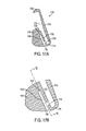
- FIG. 19A is a cross-sectional view of another embodiment of a golf club head.
- FIG. 19B is a close-up cross-sectional view of a portion of the golf club head shown in FIG. 19A .
- FIG. 19C is a close-up cross-sectional view of a golf club head having a slot including a filler material.
- FIG. 20A is a cross-sectional view of another embodiment of a golf club head.
- FIG. 20B is a close-up cross-sectional view of a portion of the golf club head shown in FIG. 20A .
- FIG. 21 is a front side view of a golf club head in accord with one embodiment of the current disclosure.
- FIG. 22A is a front side view of one exemplary embodiment of the golf club head of FIG. 21 .
- FIG. 22B is a front side view of one exemplary embodiment of the golf club head of FIG. 21 .
- FIG. 22C is a front side view of one exemplary embodiment of the golf club head of FIG. 21 .
- FIG. 22D is a front side view of one exemplary embodiment of the golf club head of FIG. 21 .
- FIG. 22E is a front side view of one exemplary embodiment of the golf club head of FIG. 21 .
- FIG. 23 is a front side view of a golf club head in accord with one embodiment of the current disclosure.
- FIG. 24A is a front side view of one exemplary embodiment of the golf club head of FIG. 23 .
- FIG. 24B is a front side view of one exemplary embodiment of the golf club head of FIG. 23 .
- FIG. 24C is a front side view of one exemplary embodiment of the golf club head of FIG. 23 .
- FIG. 24D is a front side view of one exemplary embodiment of the golf club head of FIG. 23 .
- FIG. 24E is a front side view of one exemplary embodiment of the golf club head of FIG. 23 .
- FIG. 25A is a cross-sectional view from the top a golf club head in accord with one embodiment of the current disclosure.
- FIG. 25B is a cross-sectional view from the top a golf club head in accord with one embodiment of the current disclosure.
- FIG. 26A is a front side view of a golf club head in accord with one embodiment of the current disclosure.
- FIG. 26B is a back side view of the golf club head of FIG. 26A .
- FIG. 27A is a front side view of a golf club head in accord with one embodiment of the current disclosure.
- FIG. 27B is a front side view of a golf club head in accord with one embodiment of the current disclosure.
- FIG. 28A is a back side view of a golf club head in accord with one embodiment of the current disclosure.
- FIG. 28B is a cross-sectional view of the golf club head of FIG. 28A taken in the plane indicated by line 28 B- 28 B.
- FIG. 29A is a front side view of a golf club head in accord with one embodiment of the current disclosure.
- FIG. 29B is a back side view of the golf club head of FIG. 29A .
- FIG. 29C is an alternate back side view of the golf club head of FIG. 29A .
- FIG. 30A is a front side view of a golf club head in accord with one embodiment of the current disclosure.
- FIG. 30B is a cross-sectional view of the golf club head of FIG. 30A taken in the plane indicated by line 30 B- 30 B.
- FIG. 30C is a perspective view of the golf club head of FIG. 30A .
- FIG. 31A is a front side view of a golf club head in accord with one embodiment of the current disclosure.
- FIG. 31B is a cross-sectional view of the golf club head of FIG. 31A taken in the plane indicated by line 31 B- 31 B.
- FIG. 31C is a perspective view of the golf club head of FIG. 31A .
- FIG. 32A is a front side view of a golf club head in accord with one embodiment of the current disclosure.
- FIG. 32B is a cross-sectional view of the golf club head of FIG. 32A taken in the plane indicated by line 32 B- 32 B.
- FIG. 32C is a perspective view of the golf club head of FIG. 32A .
- FIG. 33A is a front side view of a golf club head in accord with one embodiment of the current disclosure.
- FIG. 33B is a perspective view of the golf club head of FIG. 33A .
- FIG. 34A is a front side view of a golf club head in accord with one embodiment of the current disclosure.
- FIG. 34B is a perspective view of the golf club head of FIG. 34A .
- FIG. 34C is a cross-sectional view of the golf club head of FIG. 34A taken in the plane indicated by line 34 C- 34 C.
- FIG. 35A is a perspective view of a golf club head in accord with one embodiment of the current disclosure.
- FIG. 35B is a top view of the golf club head of FIG. 35A .
- FIG. 35C is a cross-sectional view of the golf club head of FIG. 35A taken in the plane indicated by line 35 C- 35 C in FIG. 35B .
- FIG. 35D is a perspective view of the golf club head of FIG. 35A .
- FIG. 36A is a perspective view of a golf club head in accord with one embodiment of the current disclosure.
- FIG. 36B is a perspective view of a golf club head in accord with one embodiment of the current disclosure.
- FIG. 37A is a perspective view of a golf club head in accord with one embodiment of the current disclosure.
- FIG. 37B is a perspective view of a golf club head in accord with one embodiment of the current disclosure.
- FIG. 38 is a front side view of various embodiments of golf club heads of the current disclosure indicating various strike locations.
- FIG. 39A is a perspective view of an experimental golf club head in accord with one embodiment of the current disclosure.
- FIG. 39B is a graph indicating COR of strikes at various locations of the golf club head of FIG. 39A .
- FIG. 40A is a perspective view of an experimental golf club head in accord with one embodiment of the current disclosure.
- FIG. 40B is a graph indicating COR of strikes at various locations of the golf club head of FIG. 40B .
- FIG. 41A is a perspective view of an experimental golf club head in accord with one embodiment of the current disclosure.
- FIG. 41B is a graph indicating COR of strikes at various locations of the golf club head of FIG. 41A .
- FIG. 42 is a modal comparison of various embodiments of golf club heads in accord with embodiments of the current disclosure.
- FIG. 43A is a front side view of a golf club head in accord with one embodiment of the current disclosure.
- FIG. 43B is a cross-sectional view of the golf club head of FIG. 43A taken along the plane indicated by line 43 B- 43 B.
- FIG. 43C is a cross-sectional view of the golf club head of FIG. 43A taken along the plane indicated by line 43 C- 43 C in FIG. 43B .
- FIG. 43D is a bottom side view of the golf club head of FIG. 43A .
- FIG. 43E is a cross-sectional view of the golf club head of FIG. 43A taken along the plane indicated by line 43 E- 43 E in FIG. 43D .
- FIG. 43F is a perspective view of the golf club head of FIG. 43A .
- FIG. 43G is a back side view of the golf club head of FIG. 43A .
- the present disclosure describes iron type golf club heads typically including a head body and a striking plate.
- the head body includes a heel portion, a toe portion, a topline portion, a sole portion, and a hosel configured to attach the club head to a shaft.
- the head body defines a front opening configured to receive the striking plate at a front rim formed around a periphery of the front opening.
- the striking plate is formed integrally (such as by casting) with the head body.
- the terms “coefficient of restitution,” “COR,” “relative coefficient of restitution,” “relative COR,” “characteristic time,” and “CT” are defined according to the following.
- the coefficient of restitution (COR) of an iron club head is measured according to procedures described by the USGA Rules of Golf as specified in the “Interim Procedure for Measuring the Coefficient of Restitution of an Iron Club head Relative to a Baseline Plate,” Revision 1.2, Nov. 30, 2005 (hereinafter “the USGA COR Procedure”). Specifically, a COR value for a baseline calibration plate is first determined, then a COR value for an iron club head is determined using golf balls from the same dozen(s) used in the baseline plate calibration. The measured calibration plate COR value is then subtracted from the measured iron club head COR to obtain the “relative COR” of the iron club head.
- a given set of golf balls may produce a measured COR value for a baseline calibration plate of 0.845.
- an iron club head may produce a measured COR value of 0.825.
- This iron club head has a COR that is 0.020 lower than the COR of the baseline calibration plate, or a relative COR of ⁇ 0.020.
- the characteristic time is the contact time between a metal mass attached to a pendulum that strikes the face center of the golf club head at a low speed under conditions prescribed by the USGA club conformance standards.
- volume when used to refer to a golf club head refers to a club head volume measured according to the procedure described in Section 5.0 of the “Procedure For Measuring the Club head Size of Wood Clubs,” Revision 1.0.0, published Nov. 21, 2003 by the United States Golf Association (the USGA) and R&A Rules Limited.
- the foregoing procedure includes submerging a club head in a large volume container of water.
- any holes or openings in the walls of the club head are to be covered or otherwise sealed prior to lowering the club head into the water.
- the iron type golf club heads include a flexible boundary structure (hereinafter “FBS”) provided at one or more locations on the club head.
- the flexible boundary structure may include, in various embodiments, a slot, a channel, a gap, a thinned or weakened region, or other structure that enhances the capability of an adjacent or related portion of the golf club head to flex or to deflect and, thereby, to provide a desired improvement in the performance of the golf club head.
- the terms “channel”, “FBS”, “slot”, and “FBS feature” may utilized interchangeably as would be understood by one of skill in the art, among other terms located herein.
- a club head for an iron-type golf club includes a body having a heel portion, a sole portion, a toe portion, a top-line portion, and a face portion, with the sole portion extending rearwardly from a lower end of the face portion.
- the face portion includes an ideal striking location (or strike location) that defines the origin of a coordinate system in which an x-axis is tangential to the face portion at the ideal striking location and is parallel to a ground plane when the body is in a normal address position, a y-axis extends perpendicular to the x-axis and is also parallel to the ground plane, and a z-axis extends perpendicular to the ground plane.
- a positive x-axis extends toward the heel portion from the origin, a positive y-axis extends rearwardly from the origin, and a positive z-axis extends upwardly from the origin.
- the body includes a central region in which ⁇ 25 mm ⁇ x ⁇ 25 mm.
- the sole portion that is contained within the central region includes a forward sole region located adjacent to the face portion and a sole bar located rearward of the forward sole region, with the forward sole region defining a wall having a minimum forward sole thickness T FS and the sole bar defining a body having a maximum sole bar thickness T SB , such that 0.05 ⁇ T FS /T SB ⁇ 0.4.
- the sole bar defines a first channel extending in a substantially heel-to-toe direction of the sole portion and having a first channel opening located on a bottom surface of the sole bar.
- the first channel has a first channel length including the distance between a part of the first channel nearest the toe portion and a part of the first channel nearest the heel region, with the first channel length being from about 15 mm to about 85 mm. In some additional embodiments, the first channel length is from about 30 mm to about 57 mm.
- the first channel has a first channel depth comprising a vertical distance between the ground plane and an uppermost point of the first channel, with an average of the first channel depth within the central region being from about 5 mm to about 25 mm. In some additional embodiments, the first channel depth is substantially constant within the central region.
- the body includes a toe side region wherein the x-axis coordinate is less than ⁇ 25 mm, and a heel side region wherein the x-axis coordinate is greater than 25 mm, and the first channel has an average depth in the central region that is less than an average depth of the first channel in the toe side region.
- the first channel has an average depth in the central region that is less than an average depth of the first channel in the heel side region.
- the first channel has an average depth in the central region that is less than an average depth of the first channel in the toe side region and that is less than an average depth of the first channel in the heel side region.
- the first channel has an average depth in the central region that is greater than an average depth of the first channel in the toe side region. In various embodiments, the first channel has an average depth in the central region that is greater than an average depth of the first channel in the heel side region. In various embodiments, the first channel has an average depth in the central region that is greater than an average depth of the first channel in the toe side region and that is greater than an average depth of the first channel in the heel side region.
- the sole bar defines a second channel extending in a substantially heel-to-toe direction of the sole bar and having a second channel opening located on an upper surface of the sole bar, the second channel having a second channel length, a second channel depth, and a second channel width.
- the central region of the body is defined as: ⁇ 20 mm ⁇ x ⁇ 20 mm. In various embodiments, the central region of the body is defined as: ⁇ 15 mm ⁇ x ⁇ 15 mm.
- 0.8 mm ⁇ T FS ⁇ 3.0 mm. In various embodiments, 1.0 mm ⁇ T FS ⁇ 2.5 mm.
- the first channel has a first channel length L 1
- the body has a sole length L B
- a ratio of the first channel length to the sole length satisfies the following inequality: 0.35 ⁇ L 1 /L B ⁇ 0.67.
- the first channel defines a first channel depth H 1 that comprises the vertical distance from the ground plane to the uppermost point of the first channel
- the body defines a body height H CH that comprises the vertical distance from the ground plane to the uppermost point of the body
- a ratio of an average value of the first channel depth H 1 within the central region to the body height H CH satisfies the following inequality: 0.07 ⁇ H 1 AVG /H CH ⁇ 0.50.
- the first channel defines a first channel centerline and the face portion defines a face plane.
- projections of the first channel centerline and the face plane onto the ground plane define a face to channel distance D 1
- the sole portion defines a sole width D 3
- a ratio of an average value of the face to channel distance D 1 within the central region to an average value of the sole width D 3 within the central region satisfies the following inequality: 0.15 ⁇ D 1 /D 3 ⁇ 0.71.
- the body defines an interior cavity, and the body has a volume V that satisfies the following inequality: 10 cc ⁇ V ⁇ 120 cc. In some of these embodiments, the body has a volume V that satisfies the following inequality: 40 cc ⁇ V ⁇ 90 cc. In some of these embodiments, the body has a volume V that satisfies the following inequality: 60 cc ⁇ V ⁇ 80 cc.
- the body defines a club head depth, D CH that satisfies the following inequality: 15 mm ⁇ D CH ⁇ 100 mm. In some of these embodiments, the body has a club head depth that satisfies the following inequality: 30 mm ⁇ D CH ⁇ 80 mm. In some of these embodiments, the body has a club head depth that satisfies the following inequality: 40 mm ⁇ D CH ⁇ 70 mm.
- a filler material is located in the first channel. In various embodiments, a filler material is located in more than one channel.
- a club head for an iron-type golf club includes a body having a heel portion, a sole portion, a toe portion, a top-line portion, and a face portion, with the sole portion extending rearwardly from a lower end of the face portion.
- the face portion includes an ideal striking location that defines the origin of a coordinate system in which an x-axis is tangential to the face portion at the ideal striking location and is parallel to a ground plane when the body is in a normal address position, a y-axis extends perpendicular to the x-axis and is also parallel to the ground plane, and a z-axis extends perpendicular to the ground plane.
- a positive x-axis extends toward the heel portion from the origin
- a positive y-axis extends rearwardly from the origin
- a positive z-axis extends upwardly from the origin.
- the body includes a central region in which ⁇ 25 mm ⁇ x ⁇ 25 mm.
- the sole portion that is contained within the central region includes a forward sole region located adjacent to the face portion and a sole bar located rearward of the forward sole region, the sole bar defining a first channel extending in a substantially heel-to-toe direction of the sole portion and having a first channel opening located on a bottom surface of the sole bar.
- the first channel defines a first channel centerline and the face portion defines a face plane, such that projections of the first channel centerline and the face plane onto the ground plane define a face to channel distance D 1 .
- the sole portion defines a sole width D 3 .
- a ratio of an average value of the face to channel distance D 1 within the central region to an average value of the sole width D 3 within the central region satisfies the following inequality: 0.15 ⁇ D 1 /D 3 ⁇ 0.71.
- the forward sole region defines a wall having a minimum forward sole thickness T FS and the sole bar defines a body having a maximum sole bar thickness T SB , such that 0.05 ⁇ T FS /T SB ⁇ 0.4.
- 0.8 mm ⁇ T FS ⁇ 3.0 mm. In various embodiments, 1.0 mm ⁇ T FS ⁇ 2.5 mm.
- the first channel has a first channel length L 1
- the body has a sole length L B
- a ratio of the first channel length to the sole length satisfies the following inequality: 0.35 ⁇ L 1 /L B ⁇ 0.67.
- the first channel defines a first channel depth H 1 that comprises the vertical distance from the ground plane to the uppermost point of the first channel
- the body defines a body height H CH that comprises the vertical distance from the ground plane to the uppermost point of the body
- a ratio of an average value of the first channel depth H 1 within the central region to the body height H CH satisfies the following inequality: 0.07 ⁇ H 1 AVG /H CH ⁇ 0.50.
- the body defines an interior cavity, and the body has a volume V that satisfies the following inequality: 10 cc ⁇ V ⁇ 120 cc. In some of these embodiments, the body has a volume V that satisfies the following inequality: 40 cc ⁇ V ⁇ 90 cc. In some of these embodiments, the body has a volume V that satisfies the following inequality: 60 cc ⁇ V ⁇ 80 cc.
- the body defines a club head depth, D CH that satisfies the following inequality: 15 mm ⁇ D CH ⁇ 100 mm. In some of these embodiments, the body has a club head depth that satisfies the following inequality: 30 mm ⁇ D CH ⁇ 80 mm. In some of these embodiments, the body has a club head depth that satisfies the following inequality: 40 mm ⁇ D CH ⁇ 70 mm.
- a filler material is located in the first channel. In various embodiments, a filler material is located in more than one channel.
- a club head for an iron-type golf club includes a body having a heel portion, a sole portion, a toe portion, a top-line portion, and a face portion, with the sole portion extending rearwardly from a lower end of the face portion.
- the face portion includes an ideal striking location that defines the origin of a coordinate system in which an x-axis is tangential to the face portion at the ideal striking location and is parallel to a ground plane when the body is in a normal address position, a y-axis extends perpendicular to the x-axis and is also parallel to the ground plane, and a z-axis extends perpendicular to the ground plane.
- a positive x-axis extends toward the heel portion from the origin
- a positive y-axis extends rearwardly from the origin
- a positive z-axis extends upwardly from the origin.
- the sole portion includes a forward sole region located adjacent to the face portion and a sole bar located rearward of the forward sole region, with the sole bar defining a first channel extending in a substantially heel-to-toe direction of the sole portion and having a first channel opening located on a bottom surface of the sole bar.
- the first channel has a first channel length L 1
- the body has a sole length L B
- a ratio of the first channel length to the sole length satisfies the following inequality: 0.35 ⁇ L 1 /L B ⁇ 0.67.
- the forward sole region defines a wall having a minimum forward sole thickness T FS and the sole bar defines a body having a maximum sole bar thickness T SB , such that 0.05 ⁇ T FS /T SB ⁇ 0.4.
- 0.8 mm ⁇ T FS ⁇ 3.0 mm. In various embodiments, 1.0 mm ⁇ T FS ⁇ 2.5 mm.
- the first channel defines a first channel depth H 1 that includes the vertical distance from the ground plane to the uppermost point of the first channel
- the body defines a body height H CH that includes the vertical distance from the ground plane to the uppermost point of the body
- a ratio of an average value of the first channel depth H 1 within the central region to the body height H CH satisfies the following inequality: 0.07 ⁇ H 1 AVG /H CH ⁇ 0.50.
- the body defines an interior cavity, and the body has a volume V that satisfies the following inequality: 10 cc ⁇ V ⁇ 120 cc. In some of these embodiments, the body has a volume V that satisfies the following inequality: 40 cc ⁇ V ⁇ 90 cc. In some of these embodiments, the body has a volume V that satisfies the following inequality: 60 cc ⁇ V ⁇ 80 cc.
- the body defines a club head depth, D CH that satisfies the following inequality: 15 mm ⁇ D CH ⁇ 100 mm. In some of these embodiments, the body has a club head depth that satisfies the following inequality: 30 mm ⁇ D CH ⁇ 80 mm. In some of these embodiments, the body has a club head depth that satisfies the following inequality: 40 mm ⁇ D CH ⁇ 70 mm.
- a filler material is located in the first channel. In various embodiments, a filler material is located in more than one channel.
- a club head for an iron-type golf club includes a body having a heel portion, a sole portion, a toe portion, a top-line portion, and a face portion, with the sole portion extending rearwardly from a lower end of the face portion.
- the face portion includes an ideal striking location that defines the origin of a coordinate system in which an x-axis is tangential to the face portion at the ideal striking location and is parallel to a ground plane when the body is in a normal address position, a y-axis extends perpendicular to the x-axis and is also parallel to the ground plane, and a z-axis extends perpendicular to the ground plane.
- a positive x-axis extends toward the heel portion from the origin, a positive y-axis extends rearwardly from the origin, and a positive z-axis extends upwardly from the origin.
- the body includes a central region in which ⁇ 25 mm ⁇ x ⁇ 25 mm.
- the sole portion that is contained within the central region includes a forward sole region located adjacent to the face portion and a sole bar located rearward of the forward sole region, the sole bar defining a first channel extending in a substantially heel-to-toe direction of the sole portion and having a first channel opening located on a bottom surface of the sole bar.
- the first channel defines a first channel depth H 1 that comprises the vertical distance from the ground plane to the uppermost point of the first channel
- the body defines a body height H CH that comprises the vertical distance from the ground plane to the uppermost point of the body
- a ratio of an average value of the first channel depth H 1 within the central region to the body height H CH satisfies the following inequality: 0.07 ⁇ H 1 AVG /H CH ⁇ 0.50.
- the forward sole region defines a wall having a minimum forward sole thickness T FS and the sole bar defines a body having a maximum sole bar thickness T SB , such that 0.05 ⁇ T FS /T SB ⁇ 0.4.
- 0.8 mm ⁇ T FS ⁇ 3.0 mm. In various embodiments, 1.0 mm ⁇ T FS ⁇ 2.5 mm.
- the first channel has a first channel length L 1
- the body has a sole length L B
- a ratio of the first channel length to the sole length satisfies the following inequality: 0.35 ⁇ L 1 /L B ⁇ 0.67.
- the body defines an interior cavity, and the body has a volume V that satisfies the following inequality: 10 cc ⁇ V ⁇ 120 cc. In some of these embodiments, the body has a volume V that satisfies the following inequality: 40 cc ⁇ V ⁇ 90 cc. In some of these embodiments, the body has a volume V that satisfies the following inequality: 60 cc ⁇ V ⁇ 80 cc.
- the body defines a club head depth, D CH that satisfies the following inequality: 15 mm ⁇ D CH ⁇ 100 mm. In some of these embodiments, the body has a club head depth that satisfies the following inequality: 30 mm ⁇ D CH ⁇ 80 mm. In some of these embodiments, the body has a club head depth that satisfies the following inequality: 40 mm ⁇ D CH ⁇ 70 mm.
- a filler material is located in the first channel. In various embodiments, a filler material is located in more than one channel.
- a set of iron-type golf clubs includes a first subset of at least one iron-type golf club and a second subset of at least one iron-type golf club.
- the first subset includes at least one club head with a loft that is less than or equal to 30°, a face portion, a heel portion, a toe portion, a sole portion, and a top-line portion, with the sole portion defining a flexible boundary structure comprising a slot or a channel having a length of from about 15 mm to about 85 mm.
- the second subset includes at least one club head with a loft that is greater than 30°, a face portion, a heel portion, a toe portion, a sole portion, and a top-line portion, with the sole portion having no flexible boundary structure comprising a slot or a channel having a length of from about 15 mm to about 85 mm.
- the first subset includes at least two golf clubs, at least three golf clubs, at least four golf clubs, or at least five golf clubs.
- the second subset includes at least two golf clubs, at least three golf clubs, at least four golf clubs, or at least five golf clubs.
- each of the golf clubs of the first subset includes a body having a heel portion, a sole portion, a toe portion, a top-line portion, and a face portion, with the sole portion extending rearwardly from a lower end of the face portion.
- the face portion includes an ideal striking location that defines the origin of a coordinate system in which an x-axis is tangential to the face portion at the ideal striking location and is parallel to a ground plane when the body is in a normal address position, a y-axis extends perpendicular to the x-axis and is also parallel to the ground plane, and a z-axis extends perpendicular to the ground plane.
- a positive x-axis extends toward the heel portion from the origin, a positive y-axis extends rearwardly from the origin, and a positive z-axis extends upwardly from the origin.
- the body includes a central region in which ⁇ 25 mm ⁇ x ⁇ 25 mm.
- the sole portion that is contained within the central region includes a forward sole region located adjacent to the face portion and a sole bar located rearward of the forward sole region, with the forward sole region defining a wall having a minimum forward sole thickness T FS and the sole bar defining a body having a maximum sole bar thickness T SB , such that 0.05 ⁇ T FS /T SB ⁇ 0.4.
- the sole bar defines a first channel extending in a substantially heel-to-toe direction of the sole portion and having a first channel opening located on a bottom surface of the sole bar.
- 0.8 mm ⁇ T FS ⁇ 3.0 mm. In various embodiments, 1.0 mm ⁇ T FS ⁇ 2.5 mm.
- the first channel has a first channel length L 1
- the body has a sole length L B
- a ratio of the first channel length to the sole length satisfies the following inequality: 0.35 ⁇ L 1 /L B ⁇ 0.67.
- the first channel defines a first channel depth H 1 that comprises the vertical distance from the ground plane to the uppermost point of the first channel
- the body defines a body height H CH that comprises the vertical distance from the ground plane to the uppermost point of the body
- a ratio of an average value of the first channel depth H 1 within the central region to the body height H CH satisfies the following inequality: 0.07 ⁇ H 1 AVG /H CH ⁇ 0.50.
- the first channel defines a first channel centerline and the face portion defines a face plane.
- projections of the first channel centerline and the face plane onto the ground plane define a face to channel distance D 1
- the sole portion defines a sole width D 3
- a ratio of an average value of the face to channel distance D 1 within the central region to an average value of the sole width D 3 within the central region satisfies the following inequality: 0.15 ⁇ D 1 /D 3 ⁇ 0.71.
- the body defines an interior cavity, and the body has a volume V that satisfies the following inequality: 10 cc ⁇ V ⁇ 120 cc. In some of these embodiments, the body has a volume V that satisfies the following inequality: 40 cc ⁇ V ⁇ 90 cc. In some of these embodiments, the body has a volume V that satisfies the following inequality: 60 cc ⁇ V ⁇ 80 cc.
- the body defines a club head depth, D CH that satisfies the following inequality: 15 mm ⁇ D CH ⁇ 100 mm. In some of these embodiments, the body has a club head depth that satisfies the following inequality: 30 mm ⁇ D CH ⁇ 80 mm. In some of these embodiments, the body has a club head depth that satisfies the following inequality: 40 mm ⁇ D CH ⁇ 70 mm.
- a club head for an iron-type golf club includes a body having a heel portion, a sole portion, a toe portion, a top-line portion, and a face portion, wherein said sole portion extends rearwardly from a lower end of said face portion, the body further defining a rear void.
- the face portion includes an ideal striking location that defines the origin of a coordinate system in which an x-axis is tangential to the face portion at the ideal striking location and is parallel to a ground plane when the body is in a normal address position, a y-axis extends perpendicular to the x-axis and is also parallel to the ground plane, and a z-axis extends perpendicular to the ground plane.
- a positive x-axis extends toward the heel portion from the origin, a positive y-axis extends rearwardly from the origin, and a positive z-axis extends upwardly from the origin.
- the body includes a central region in which ⁇ 25 mm ⁇ x ⁇ 25 mm.
- the sole portion that is contained within the central region includes a forward sole region located adjacent to the face portion and a sole bar located rearward of the forward sole region, with the forward sole region defining a wall having a minimum forward sole thickness T FS and the sole bar defining a body having a maximum sole bar thickness T SB , such that 0.05 ⁇ T FS /T SB ⁇ 0.4.
- the sole portion includes a slot extending in a substantially heel-to-toe direction of the sole portion, the slot defining a portion of a path that extends through the sole portion and into the rear void.
- the slot has a slot length comprising the distance between a part of the slot nearest the toe portion and a part of the slot nearest the heel region, with the slot length being from about 15 mm to about 85 mm.
- the slot has a slot length L 1
- the body has a sole length L B
- a ratio of the slot length to the sole length satisfies the following inequality: 0.35 ⁇ L 1 /L B ⁇ 0.67.
- the body defines an interior cavity, and the body has a volume V that satisfies the following inequality: 10 cc ⁇ V ⁇ 120 cc.
- a filler material is located in the slot. In various embodiments, a filler material is located in more than one channel.
- the face portion defines a face plane and the path includes a lower path portion having a length of at least 1 mm and defining a lower path angle that is within 30° of being parallel with said face plane, an intermediate path portion having a length of at least 1 mm and defining an intermediate path angle that is within 30° of being perpendicular to said face plane, and an upper path portion having a length of at least 1 mm and defining an upper path angle that is within 30° of being parallel with said face plane.
- a club head for an iron-type golf club includes a body having a heel portion, a sole portion, a toe portion, a top-line portion, and a face portion, wherein said sole portion extends rearwardly from a lower end of said face portion, the body further defining a rear void.
- the face portion includes an ideal striking location that defines the origin of a coordinate system in which an x-axis is tangential to the face portion at the ideal striking location and is parallel to a ground plane when the body is in a normal address position, a y-axis extends perpendicular to the x-axis and is also parallel to the ground plane, and a z-axis extends perpendicular to the ground plane.
- a positive x-axis extends toward the heel portion from the origin, a positive y-axis extends rearwardly from the origin, and a positive z-axis extends upwardly from the origin.
- the body includes a central region in which ⁇ 25 mm ⁇ x ⁇ 25 mm.
- the sole portion that is contained within the central region includes a forward sole region located adjacent to the face portion and a sole bar located rearward of the forward sole region, with the forward sole region defining a wall having a minimum forward sole thickness T FS and the sole bar defining a body having a maximum sole bar thickness T SB .
- the sole portion includes a slot extending in a substantially heel-to-toe direction of the sole portion, the slot defining a portion of a path that extends through the sole portion and into the rear void, with the path including a lower path portion having a length of at least 1 mm and defining a lower path angle that is within 30° of being parallel with said face plane, an intermediate path portion having a length of at least 1 mm and defining an intermediate path angle that is within 30° of being perpendicular to said face plane, and an upper path portion having a length of at least 1 mm and defining an upper path angle that is within 30° of being parallel with said face plane.
- the slot has a slot length comprising the distance between a part of the slot nearest the toe portion and a part of the slot nearest the heel region, with the slot length being from about 15 mm to about 85 mm.
- the slot has a slot length L 1
- the body has a sole length L B
- a ratio of the slot length to the sole length satisfies the following inequality: 0.35 ⁇ L 1 /L B ⁇ 0.67.
- the body defines an interior cavity, and the body has a volume V that satisfies the following inequality: 10 cc ⁇ V ⁇ 120 cc.
- a filler material is located in the slot. In various embodiments, a filler material is located in more than one channel.
- flexible boundary structures may be found in various locations on the golf club head, including defined within the striking face, defined within the sole portion, and defined within the perimeter of the golf club head. Various performance characteristics may be altered by location, size, and arrangement of various channels. Various relief features may be utilized to provide durability and performance of the various flexible boundary structures. In various embodiments, flexible boundary structures may alter auditory profile of the golf club head thereby allowing for the isolation of preferred auditory profile of the golf club head.
- FIG. 1A illustrates an iron type golf club head 100 including a body 113 having a heel 102 , a toe portion 104 , a sole portion 108 , a top line portion 106 , and a hosel 114 .
- the golf club head 100 is shown in FIG. 1A in a normal address position with the sole portion 108 resting upon a ground plane 111 , which is assumed to be perfectly flat.
- normal address position means the club head position wherein a vector normal to the center of the club face substantially lies in a first vertical plane (i.e., a vertical plane is perpendicular to the ground plane 111 ), a centerline axis 115 of the hosel 114 substantially lies in a second vertical plane, and the first vertical plane and the second vertical plane substantially perpendicularly intersect.
- the center of the club face is determined using the procedures described in the USGA “Procedure for Measuring the Flexibility of a Golf Club head,” Revision 2.0, Mar. 25, 2005.
- a lower tangent point 190 on the outer surface of the club head 100 of a line 191 forming a 45° angle relative to the ground plane 111 defines a demarcation boundary between the sole portion 108 and the toe portion 104 .
- an upper tangent point 192 on the outer surface of the club head 100 of a line 193 forming a 45° angle relative to the ground plane 111 defines a demarcation boundary between the top line portion 106 and the toe portion 104 .
- the portion of the club head that is above and to the left (as viewed in FIG. 1A ) of the lower tangent point 190 and below and to the left (as viewed in FIG. 1A ) of the upper tangent point 192 is the toe portion 104 .
- the striking face 110 defines a face plane 125 and includes grooves 112 that are designed for impact with the golf ball.
- the toe portion 104 may be understood to be any portion of the golf club head 100 that is toeward of the grooves 112 .
- the golf club head 100 can be a single unitary cast piece, while in other embodiments, a striking plate can be formed separately to be adhesively or mechanically attached to the body 113 of the golf club head 100 .
- FIGS. 1A and 1B also show an ideal striking location 101 on the striking face 110 and respective orthogonal CG axes.
- the ideal striking location 101 is located within the face plane 125 and coincides with the location of the center of gravity (CG) of the golf club head along the CG x-axis 105 (i.e., CG-x) and is offset from the leading edge 142 (defined as the midpoint of a radius connecting the sole portion 108 and the face plane 125 ) by a distance d of 16.5 mm within the face plane 125 , as shown in FIG. 1B .
- CG center of gravity
- a CG x-axis 105 , CG y-axis 107 , and CG z-axis 103 intersect at the ideal striking location 101 , which defines the origin of the orthogonal CG axes.
- the CG x-axis 105 is parallel to the ground plane 111 and is oriented perpendicular to a normal extending from the striking face 110 at the ideal striking location 101 .
- the CG y-axis 107 is also parallel to the ground plane and is perpendicular to the CG x-axis 105 .
- the CG z-axis 103 is oriented perpendicular to the ground plane.
- a CG z-up axis 109 is defined as an axis perpendicular to the ground plane 111 and having an origin at the ground plane 111 .
- a desirable CG-y location is between about 0.25 mm to about 20 mm along the CG y-axis 107 toward the rear portion of the club head. Additionally, a desirable CG-z location is between about 12 mm to about 25 mm along the CG z-up axis 109 , as previously described.
- the golf club head may be of solid (also referred to as “blades” and/or “musclebacks”), hollow, cavity back, or other construction.
- FIG. 1C shows a cross sectional side view along the cross-section lines 1 C- 1 C shown in FIG. 1A of an embodiment of the golf club head having a hollow construction.
- FIG. 1D shows a cross sectional side view along the cross-section lines 1 D- 1 D of an embodiment of a golf club head having a cavity back construction.
- the cross-section lines 1 C, 1 D- 1 C, 1 D are taken through the ideal striking location 101 on the striking face 110 .
- the striking face 110 includes a front surface 110 a and a rear surface 110 b .
- Both the hollow iron golf club head and cavity back iron golf club head embodiments further include a back portion 128 and a front portion 130 .
- the grooves 112 are located on the striking face 110 such that they are centered along the CG x-axis about the ideal striking location 101 , i.e., such that the ideal striking location 101 is located within the striking face plane 125 on an imaginary line that is both perpendicular to and that passes through the midpoint of the longest score-line groove 112 .
- the grooves 112 may be shifted along the CG x-axis to the toe side or the heel side relative to the ideal striking location 101 , the grooves 112 may be aligned along an axis that is not parallel to the ground plane 111 , the grooves 112 may have discontinuities along their lengths, or the grooves may not be present at all. Still other shapes, alignments, and/or orientations of grooves 112 on the surface of the striking face 110 are also possible.
- the club head 100 has a sole length, L B , and a club head height, H CH .
- the sole length, L B is defined as the distance between two points projected onto the ground plane 111 .
- a heel side 116 of the sole is defined as the intersection of a projection of the hosel axis 115 onto the ground plane 111 .
- a toe side 117 of the sole is defined as the intersection point of the vertical projection of the lower tangent point 190 (described above) onto the ground plane 111 .
- the distance between the heel side 116 and toe side 117 of the sole is the sole length L B of the club head.
- the club head height, H CH is defined as the distance between the ground plane 111 and the uppermost point of the club head as projected in the x-z plane, as illustrated in FIG. 1A .
- FIG. 1B illustrates an elevated toe view of the golf club head 100 including a back portion 128 , a front portion 130 , a sole portion 108 , a top line portion 106 , and a striking face 110 , as previously described.
- a leading edge 142 is defined by the midpoint of a radius connecting the face plane 125 and the sole portion 108 .
- the club head includes a club head front-to-back depth, D CH , which is the distance between two points projected onto the ground plane 111 .
- D CH club head front-to-back depth
- a forward end 118 of the club head is defined as the intersection of the projection of the leading edge 142 onto the ground plane 111 .
- a rearward end 119 of the club head is defined as the intersection of the projection of the rearward-most point of the club head (as viewed in the y-z plane) onto the ground plane 111 .
- the distance between the forward end 118 and rearward end 119 of the club head is the club head depth D CH .
- a recess 134 is located above the rear protrusion 138 in the back portion 128 of the club head.
- a back wall 132 encloses the entire back portion 128 of the club head to define an interior cavity 120 .
- the interior cavity 120 may be completely or partially hollow, or it optionally may be filled with a filler material.
- the interior cavity 120 includes a vibration dampening plug 121 that is retained between the rear surface 110 b of the striking face and the inner surface 132 b of the back wall. Suitable filler materials and details relating to the nature and materials comprising the plug 121 are described in US Patent Application Publication No. 2011/0028240, which is incorporated herein by reference.
- FIG. 1C further shows an optional ridge 136 extending across a portion of the outer back wall surface 132 a forming an upper concavity and a lower concavity.
- An inner back wall surface 132 b defines a portion of the cavity 120 and forms a thickness between the outer back wall surface 132 a and the inner back wall surface 132 b .
- the back wall thickness varies between a thickness of about 0.5 mm to about 4 mm.
- a sole bar 135 is located in a low, rearward portion of the club head 100 .
- the sole bar 135 has a relatively large thickness in relation to the striking plate and other portions of the club head 100 , thereby accounting for a significant portion of the mass of the club head 100 , and thereby shifting the center of gravity (CG) of the club head 100 relatively lower and rearward.
- a channel 150 is formed in the sole bar 135 .
- the sole portion 108 has a forward portion 144 that is located immediately rearward of the striking face 110 .
- the forward portion 144 of the sole is a relatively thin-walled section of the sole that extends within a region between the channel 150 and the striking face 110 .
- FIG. 1D further shows a sole bar 135 of the cavity back golf club head 100 .
- the sole bar 135 has a relatively large thickness in relation to the striking plate and other portions of the golf club head 100 , thereby accounting for a significant portion of the mass of the golf club head 100 , and thereby shifting the center of gravity (CG) of the golf club head 100 relatively lower and rearward.
- the embodiment shown in FIG. 1D also includes a forward portion 144 of the sole that has a reduced sole thickness and that extends within between the sole bar 135 and the striking face 110 .
- a channel 150 is located in a forward region of the sole bar 135 .
- FIG. 1E shows another embodiment of a hollow iron club head 100 having a channel 150 .
- the club head 100 includes a striking face 110 , a top line 106 , a sole 108 , and a back wall 132 .
- the sole includes a sole bar 135 having a channel 150 defined by a forward wall 152 and rear wall 154 .
- a forward portion 144 of the sole is located between the striking face 110 and the forward wall 152 of the slot.
- the hollow club head 100 includes an aperture 133 that is suitable for installing a vibration dampening plug 121 like that shown in FIG. 1C , and which is described in more detail in US Patent Application Publication No. 2011/0028240, which is incorporated by reference. Installation of the vibration dampening plug 121 effectively seals the aperture 133 .
- the volume of the hollow iron club head 100 may be between about 10 cubic centimeters (cc) and about 120 cc.
- the hollow iron club head 100 may have a volume between about 20 cc and about 110 cc, such as between about 30 cc and about 100 cc, such as between about 40 cc and about 90 cc, such as between about 50 cc and about 80 cc, such as between about 60 cc and about 80 cc.
- the hollow iron club head 100 has a club head depth, D CH , that is between about 15 mm and about 100 mm.
- the hollow iron club head 100 may have a club head depth, D CH , of between about 20 mm and about 90 mm, such as between about 30 mm and about 80 mm, such as between about 40 mm and about 70 mm.
- the striking plate can be formed of forged maraging steel, maraging stainless steel, or precipitation-hardened (PH) stainless steel.
- maraging steels have high strength, toughness, and malleability. Being low in carbon, they derive their strength from precipitation of inter-metallic substances other than carbon.
- the principle alloying element is nickel (15% to nearly 30%). Other alloying elements producing inter-metallic precipitates in these steels include cobalt, molybdenum, and titanium.
- the maraging steel contains 18% nickel. Maraging stainless steels have less nickel than maraging steels but include significant chromium to inhibit rust.
- chromium augments hardenability despite the reduced nickel content, which ensures the steel can transform to martensite when appropriately heat-treated.
- a maraging stainless steel C455 is utilized as the striking plate.
- the striking plate is a precipitation hardened stainless steel such as 17-4, 15-5, or 17-7.
- the striking plate can be forged by hot press forging using any of the described materials in a progressive series of dies. After forging, the striking plate is subjected to heat-treatment. For example, 17-4 PH stainless steel forgings are heat treated by 1040° C. for 90 minutes and then solution quenched. In another example, C455 or C450 stainless steel forgings are solution heat-treated at 830° C. for 90 minutes and then quenched.
- the body 113 of the golf club head is made from 17-4 steel.
- another material such as carbon steel (e.g., 1020, 1030, 8620, or 1040 carbon steel), chrome-molybdenum steel (e.g., 4140 Cr—Mo steel), Ni—Cr—Mo steel (e.g., 8620 Ni—Cr—Mo steel), austenitic stainless steel (e.g., 304, N50, or N60 stainless steel (e.g., 410 stainless steel) can be used.
- metals and metal alloys that can be used to form the components of the parts described include, without limitation: titanium alloys (e.g., 3-2.5, 6-4, SP700, 15-3-3-3, 10-2-3, or other alpha/near alpha, alpha-beta, and beta/near beta titanium alloys), aluminum/aluminum alloys (e.g., 3000 series alloys, 5000 series alloys, 6000 series alloys, such as 6061-T6, and 7000 series alloys, such as 7075), magnesium alloys, copper alloys, and nickel alloys.
- titanium alloys e.g., 3-2.5, 6-4, SP700, 15-3-3-3, 10-2-3, or other alpha/near alpha, alpha-beta, and beta/near beta titanium alloys
- aluminum/aluminum alloys e.g., 3000 series alloys, 5000 series alloys, 6000 series alloys, such as 6061-T6, and 7000 series alloys, such as 7075
- magnesium alloys copper
- the body 113 and/or striking plate of the golf club head are made from fiber-reinforced polymeric composite materials, and are not required to be homogeneous. Examples of composite materials and golf club components comprising composite materials are described in U.S. Patent Application Publication No. 2011/0275451, which is incorporated herein by reference in its entirety.
- the body 113 of the golf club head can include various features such as weighting elements, cartridges, and/or inserts or applied bodies as used for CG placement, vibration control or damping, or acoustic control or damping.
- weighting elements such as weighting elements, cartridges, and/or inserts or applied bodies as used for CG placement, vibration control or damping, or acoustic control or damping.
- U.S. Pat. No. 6,811,496, incorporated herein by reference in its entirety discloses the attachment of mass altering pins or cartridge weighting elements.
- the striking plate and body portion 113 contact surfaces can be finish-machined to ensure a good interface contact surface is provided prior to welding.
- the contact surfaces are planar for ease of finish machining and engagement.
- a flexible boundary structure (“FBS”) is provided at one or more locations on the club head.
- the flexible boundary structure may comprise, in several embodiments, at least one slot, at least one channel, at least one gap, at least one thinned or weakened region, and/or at least one other structure that enhances the capability of an adjacent or related portion of the golf club head to flex or deflect and to thereby provide a desired improvement in the performance of the golf club head.
- the flexible boundary structure is located proximate the striking face of the golf club head in order to enhance the deflection of the striking face upon impact with a golf ball during a golf swing.
- the enhanced deflection of the striking face may result, for example, in an increase or in a desired decrease in the coefficient of restitution (“COR”) of the golf club head.
- the increased perimeter flexibility of the striking face may cause the striking face to deflect in a different location and/or different manner in comparison to the deflection that occurs upon striking a golf ball in the absence of the channel, slot, or other flexible boundary structure.
- the flexible boundary structure is a channel 250 that is located on the sole of the club head.
- the flexible boundary structure may comprise a slot, a channel, a gap, a thinned or weakened region, or other structure.
- a channel such as the channel 250 illustrated in FIGS. 2A-C , or a slot, included in several embodiments described below, with it being understood that other flexible boundary structures may be used to achieve the benefits described herein.
- the channel 250 extends over a region of the sole 208 generally parallel to and spaced rearwardly from the striking face plane 225 .
- the channel extends into and is defined by a forward portion of the sole bar 235 , defining a forward wall 252 , a rear wall 254 , and an upper wall 256 .
- a channel opening 258 is defined on the sole portion 208 of the club head.
- the forward wall 252 further defines, in part, a first hinge region 260 located at the transition from the forward portion of the sole 244 to the forward wall 252 , and a second hinge region 262 located at a transition from the upper region of the forward wall 252 to the sole bar 235 .
- the first hinge region 260 and second hinge region 262 are portions of the golf club head that contribute to the increased deflection of the striking face 210 of the golf club head due to the presence of the channel 250 .
- the shape, size, and orientation of the first hinge region 260 and second hinge region 262 are designed to allow these regions of the golf club head to flex under the load of a golf ball impact. The flexing of the first hinge region 260 and second hinge region 262 , in turn, creates additional deflection of the striking face 210 .
- the face to channel distance D 1 is the distance measured on the ground plane 211 between a face plane projection point 226 and a channel centerline projection point 227 .
- the face plane projection point 226 is defined as the intersection of a projection of the striking face plane 225 onto the ground plane 211 .
- the channel centerline projection point 227 is defined as the intersection of a projection of a channel centerline 229 onto the ground plane 211 .
- the channel centerline 229 is determined according to the following.
- FIGS. 2D-E a schematic profile 249 of the outer surface of a portion of the club head 200 that surrounds and includes the region of the channel 250 is shown.
- the schematic profile has an interior side 249 a and an exterior side 249 b .
- a forward sole exterior surface 208 a extends on a forward side of the channel 250
- a rearward sole exterior surface 208 b extends on a rearward side of the channel 250 .
- the channel has a forward wall exterior surface 252 a , a rear wall exterior surface 254 a , and an upper wall exterior surface 256 a .
- a forward channel entry point 264 is defined as the midpoint of a curve having a local minimum radius (r min , measured from the interior side 249 a of the schematic profile 249 ) that is located between the forward sole exterior surface 208 a and the forward wall exterior surface 252 a .
- a rear channel entry point 265 is defined as the midpoint of a curve having a local minimum radius (r min , also measured from the interior side 249 a of the schematic profile 249 ) that is located between the rearward sole exterior surface 208 b and the rear wall exterior surface 254 a .
- An imaginary line 266 that connects the forward channel entry point 264 and the rear channel entry point 265 defines the channel opening 258 .
- a midpoint 266 a of the imaginary line 266 is one of two points that define the channel centerline 229 .
- the other point defining the channel centerline 229 is an upper channel peak 267 , which is defined as the midpoint of a curve having a local minimum radius (r min , as measured from the exterior side 249 b of the schematic profile 249 ) that is located between the forward wall exterior surface 252 a and the rear wall exterior surface 254 a .
- the upper channel peak 267 is defined as the midpoint of the flat segment(s) or flat surface(s).
- the sole width is the distance measured on the ground plane 211 between the face plane projection point 226 and a trailing edge projection point 246 .
- the face plane projection point 226 is defined above.
- the trailing edge projection point 246 is the intersection with the ground plane 211 of an imaginary vertical line passing through the trailing edge 245 of the club head 200 .
- the trailing edge 245 is defined as a midpoint of a radius or a point that constitutes a transition from the sole portion 208 to the back wall 232 or other structure on the back portion 228 of the club head.
- Still another aspect of the size, shape, and orientation of the club head 200 and channel 250 is the channel to rear distance, D 2 .
- the channel to rear distance D 2 is the distance measured on the ground plane 211 between the channel centerline projection point 227 and a vertical projection of the trailing edge 245 onto the ground plane 211 . (See FIG. 2F ).
- D 1 +D 2 D 3 .
- FIGS. 3A-B illustrate two embodiments of golf club heads 300 having a channel 350 that operates as a flexible boundary structure.
- the two embodiments are similarly designed with the exception of the face to channel distance D 1 of each embodiment, as measured at a cross-section taken at the ideal striking location 301 .
- the club head embodiment shown in FIG. 3A includes a face to channel distance D 1 that is substantially larger than the face to channel distance D 1 of the embodiment shown in FIG. 3B while the sole width D 3 (as measured at the same cross-section taken at the ideal striking location 301 ) of each of the embodiments is the same.
- Table 1 below lists several exemplary values for the face to channel distance D 1 , channel to rear distance D 2 , sole width D 3 , and the ratios of D 1 /D 3 , D 2 /D 3 , and D 1 /D 2 for several examples of club heads that include a channel 350 according to the embodiments described herein.
- the measurements reported in Table 1 are for the average face to channel distance (D 1 ), average channel to rear distance (D 2 ), and average sole width (D 3 ) over a portion of the club head extending 25 mm to each side (i.e., toe side and heel side) of the ideal striking location 301 .
- the terms “average face to channel distance (D 1 ),” “average channel to rear distance (D 2 ),” and “average sole width (D 3 )” refer to an average of a plurality of D 1 , D 2 , or D 3 measurements, with the plurality of D 1 , D 2 , or D 3 measurements being taken within a plurality of imaginary parallel vertical planes that include a first vertical plane passing through the ideal striking location 301 and that contains a vector drawn normal to the striking face 310 at the ideal striking location 301 , and a plurality of additional vertical planes that are parallel to the first vertical plane and that are spaced at regular 1 mm increments on each side of the ideal striking location 301 .
- additional aspects of the design of the club head 200 and channel 250 include the channel width W 1 , channel length L 1 , and channel depth H 1 .
- the channel width W 1 is a measure of the distance in a horizontal plane (i.e., a plane that is parallel to the ground plane 211 ) between the forward wall 252 and rear wall 254 of the channel at a given cross-section of the channel 250 .
- the channel length L 1 is generally a measure of the distance on the sole 208 of the club head between the toeward-most point of the channel and the heelward-most point of the channel, without taking into account any curvature of the channel 250 .
- the channel depth H 1 is generally a measure of the distance from the ground plane 211 to the highest point (in the y-z plane) of the inner surface of the channel on the channel upper wall 256 when the club head 200 is resting on the ground plane 211 .
- the channel 250 includes a constant width W 1 and constant depth H 1 over its full length. In other embodiments, one or more of these three parameters may be varied to achieve desired design and/or performance objectives.
- FIGS. 4A-B illustrate two embodiments of golf club heads 400 having a channel 450 that operates as a flexible boundary structure.
- the two embodiments are similarly designed with the exception of the channel width W 1 of each embodiment.
- the club head embodiment shown in FIG. 4A includes a channel width W 1 that is constant, and that is substantially smaller than the (also constant) channel width W 1 of the embodiment shown in FIG. 4B .
- a channel may have a width W 1 that is not constant. In those embodiments, an average channel width W 1 may be determined.
- the term “average channel width W 1 ” refers to an average of a plurality of W 1 measurements, with the plurality of W 1 measurements being taken within a plurality of imaginary parallel horizontal planes that include a first horizontal plane passing through a point that is located at a distance equal to one-half of the channel height H 1 above the ground plane 411 , and a plurality of additional horizontal planes that are parallel to the first horizontal plane and that are spaced at regular 0.5 mm increments above and below the first horizontal plane.
- the uppermost imaginary parallel horizontal plane is located at a height that is 80% of the channel height H 1 above the ground plane 411
- the lowermost imaginary parallel horizontal plane is located at a height that is at least 20% of the channel height H 1 above the ground plane 411 .
- the average channel width W 1 may be from about 0.50 mm to about 10.0 mm, such as from about 1.0 mm to about 4.0 mm, such as from about 1.25 mm to about 2.5 mm. In one embodiment, the average channel width W 1 is about 1.75 mm.
- the channel width W 1 at the channel opening 258 is sufficiently wide that the forward wall 252 and rear wall 254 of the channel do not contact one another when, for example, a golf ball is struck by the club head 200 , but the channel width W 1 at the channel opening 258 is sufficiently narrow that the amount of dirt, grass, and other materials entering the channel 250 may be reduced relative to a channel having a wider channel opening 258 .
- the channel width W 1 at the channel opening 258 may be from about 0.5 mm to about 5 mm, such as from about 1.0 mm to about 4 mm, such as from about 1.25 mm to about 3 mm.
- FIGS. 5A-B illustrate two embodiments of golf club heads 500 having a channel 550 that operates as a flexible boundary structure.
- the two embodiments are similarly designed with the exception of the channel depth H 1 of each embodiment.
- the club head embodiment shown in FIG. 5A includes a constant channel depth H 1 that is substantially smaller than the (also constant) channel depth H 1 of the embodiment shown in FIG. 5B .
- a channel may have a depth H 1 that is not constant.
- a maximum channel depth H 1 MAX and an average channel depth H 1 AVG may be determined.
- the term “maximum channel depth H 1 MAX ” refers to a maximum value for the channel depth H 1 occurring over the full length of the channel.
- the term “average channel depth H 1 AVG ” refers to an average of H 1 measurements, with the plurality of H 1 measurements being taken within a plurality of imaginary parallel vertical planes that include a first vertical plane passing through the ideal striking location 501 and that contains a vector drawn normal to the striking face 510 at the ideal striking location 501 , and a plurality of additional vertical planes that are parallel to the first vertical plane and that are spaced at regular 1 mm increments on each side of the ideal striking location 501 .
- Table 2 below lists several exemplary values for the average channel depth H 1 AVG , maximum channel depth H 1 MAX , club head height H CH , and the ratios of H 1 AVG /H CH and H 1 MAX /H CH for several examples of club heads that include a channel according to the embodiments described herein.
- H1AVG H1MAX HCH H1AVG/ H1MAX/ Loft (mm) (mm) (mm) HCH HCH Ex. 1 20-21° 5.0-25.0 5.0-45 25-75 0.07-0.50 0.07-0.70 (4I) 6.0-14.5 6.0-30 35-65 0.10-0.41 0.10-0.60 8.5-13.0 8.5-23 40-60 0.14-0.33 0.14-0.50
- Ex. 2 26-28° 5.0-25.0 5.0-45 25-75 0.07-0.50 0.07-0.70 (6I) 6.0-14.5 6.0-30 35-65 0.10-0.41 0.10-0.60 8.5-13.0 8.5-23 40-60 0.14-0.33 0.14-0.50
- FIGS. 6A-B illustrate two embodiments of golf club heads 600 having a channel 650 that operates as a flexible boundary structure.
- the two embodiments are similarly designed with the exception of the channel length L 1 of each embodiment.
- the club head embodiment shown in FIG. 6A includes a channel length L 1 that is substantially shorter than the channel length L 1 of the embodiment shown in FIG. 6B .
- the channel length L 1 may be from about 15 mm to about 62 mm, such as from about 40 mm to about 57 mm, such as from about 45 mm to about 55 mm. In one embodiment, the channel length L 1 is about 50 mm.
- Table 3 below lists several exemplary values for the channel length L 1 , sole length L B , and the ratio of L 1 /L B for several examples of club heads that include a channel according to the embodiments described herein.
- Table 4 lists several exemplary values for the channel length L 1 , the average channel depth H 1 AVG , the maximum channel depth H 1 MAX , and the ratios of H 1 AVG /L 1 and H 1 MAX /L 1 for several examples of club heads that include a channel according to the embodiments described herein.
- a first wall thickness, T 1 is a measure of the thickness of the first hinge region 260 .
- a second wall thickness, T 2 is a measure of the thickness of the second hinge region 262 .
- a forward sole wall minimum thickness, T FS is a measure of the minimum thickness (measured in a vertical plane) of the forward portion 244 of the sole, i.e., the portion of the sole 208 located between the striking face 210 and the channel 250 .
- a sole bar maximum thickness T SB is a measure of the maximum thickness (measured in a vertical plane) of the portion of the sole bar 235 located rearward of the channel 250 .
- the club head 200 includes a first hinge region 260 , second hinge region 262 , and forward portion 244 of the sole that each have a constant thickness over their full lengths. In other embodiments, one or more of these parameters may be varied to achieve desired design and/or performance objectives.
- FIGS. 7A-B illustrate two embodiments of golf club heads 700 having a channel 750 that operates as a flexible boundary structure.
- the two embodiments are similarly designed with the exception of the orientation of the channel 750 and the resultant variation in the thickness, T 1 , of the first hinge region of each embodiment.
- the club head embodiment shown in FIG. 7A includes a first hinge region thickness T 1 that is substantially smaller/thinner than the first hinge region thickness T 1 of the embodiment shown in FIG. 7B .
- the first hinge region thickness T 1 may be from about 0.5 mm to about 5.0 mm, such as from about 1.0 mm to about 3.0 mm, such as from about 1.2 mm to about 2.0 mm. In one embodiment, the first hinge region thickness T 1 is about 1.5 mm.
- FIGS. 8A-B illustrate two embodiments of golf club heads 800 having a channel 850 that operates as a flexible boundary structure.
- the two embodiments are similarly designed with the exception of the orientation of the channel 850 and the resultant variation in the thickness, T 2 , of the second hinge region of each embodiment.
- the club head embodiment shown in FIG. 8A includes a second hinge region thickness T 2 that is substantially smaller/thinner than the second hinge region thickness T 2 of the embodiment shown in FIG. 8B .
- the second hinge region thickness T 2 may be from about 0.5 mm to about 5.0 mm, such as from about 1.0 mm to about 2.5 mm, such as from about 1.2 mm to about 2.0 mm. In one embodiment, the second hinge region thickness T 2 is about 1.5 mm.
- Table 5 lists several exemplary values for the forward sole minimum thickness T FS , sole bar maximum thickness T SB , and the ratio of T FS /T SB for several examples of club heads that include a channel according to the embodiments described herein.
- the channel 250 shown in the illustrated embodiment includes a forward channel wall 252 that is generally parallel to the striking face 210 , and that is also generally parallel to the rear channel wall 254 .
- the channel width W 1 is substantially constant over the depth of the channel.
- a club head 900 includes a channel 950 having a forward channel wall 952 , rear channel wall 954 , and upper channel wall 956 .
- the forward channel wall 952 and rear channel wall 954 are not parallel to one another, defining an included angle ⁇ that may be from slightly greater than 0° to about 25° or more.
- the channel is defined by forward, rear, and upper walls, and has a channel opening that is formed on the sole portion of the club head. Accordingly, except for the channel opening, each of the channels described above is closed at its forward, rear, and upper ends.
- a channel instead of a closed channel, a channel may be provided having one or more openings that extend through one or more of the channel walls, and/or a slot having no upper wall extends fully through the sole portion (or other portion) of the club head in which it is located.
- a cavity back iron golf club head 1700 includes a channel 1750 that is defined in part by a forward wall 1752 , rear wall 1754 , and upper wall 1756 .
- the club head also includes a top line 1706 , a striking face 1710 , a forward portion of the sole 1744 , and a sole bar 1735 , as described in relation to the embodiments described above.
- the club head 1700 may comprise a hollow iron (see, e.g., FIGS. 1C and 1E ).
- One or more cutouts or windows 1794 are provided on the forward wall 1752 of the channel. See, e.g., FIGS. 18A-B .
- Each window 1794 provides increased flexibility to the forward channel wall 1752 , thereby increasing the capability of the flexible boundary structure (FBS) provided by the channel 1750 to flex or deflect and to thereby provide a desired improvement in the performance of the golf club head.
- the forward wall 1752 includes three cutouts or windows 1794 that are generally equally spaced along the heel-to-toe length of the forward wall 1752 . In alternative embodiments, fewer (e.g., one or two) or more (e.g., four or more) cutouts or windows 1794 may be provided.
- a representative cutout or window 1794 has a length L w which corresponds to the distance between the toeward-most and heelward-most ends of the window 1794 , and a height H w that corresponds to the distance between the crownward-most and soleward-most ends of the window 1794 .
- the length L w may be from about 1 mm to as much as the length L 1 of the channel 1750 , such as up to about 85 mm (e.g., in an embodiment that includes only a single window 1794 ).
- the windows each have a length L w of from about 3 mm to about 18 mm, such as from about 6 mm to about 15 mm, such as from about 8 mm to about 12 mm.
- the height H w may be from about 0.5 mm to as much as the height H 1 of the channel 1750 , such as up to about 25 mm.
- the windows each have a height H w of from about 0.5 mm to about 15 mm, such as from about 1 mm to about 12 mm, such as from about 1.5 mm to about 8 mm.
- one or more windows or cutouts may be formed through the channel rear wall 1754 and extending through the sole bar 1735 , with an exit port provided on a rearward-facing surface of the club head.
- a cavity back iron club head 1000 includes a slot 1050 that extends fully through the sole 1008 into the recess 1034 at the back portion of the club head.
- a hollow iron may include a slot that extends fully through the sole and into the interior cavity of the club head.
- the embodiment shown in FIG. 10A also shows a slot 1050 with an opening 1058 that has a non-straight, curved shape when viewing the sole of the club head.
- the slot 1050 may be straight or may have a curved shape that is different from the embodiment shown in FIG. 10A , several of which are described below.
- the slot opening 1058 is continuous and includes a first curved region 1070 and a second curved region 1072 . Each of the first and second curved regions 1070 , 1072 defines a generally semi-circular shape.
- the first curved region 1070 has a peak 1070 a that represents a point at which the first curved region 1070 is nearest to the leading edge 1042 , and that is located on the toeward half of the club head 1000 .
- the second curved region 1072 has a peak 1072 a that represents a point at which the second curved region 1072 is nearest to the leading edge 1042 , and that is located on the heelward half of the club head 1000 .
- a center connecting region 1073 connects the first and second curved regions 1070 , 1072 , and is typically centered at or near the 0 coordinate of the CG x-axis 105 .
- the slot 1050 is located rearward of the forward portion 1044 of the sole and forward of the sole bar 1035 .
- the slot 1050 has a face to slot distance, D 1 , that is variable over the length of the slot 1050 due to the curvature of the first curved region 1070 and second curved region 1072 .
- the face to slot distance may be comparable to the ranges for the face to channel distance D 1 of the embodiments described above in relation to FIGS. 2A-H and FIGS. 3A-B .
- the slot 1050 also has a slot length, L 1 , that may be comparable to the ranges for the channel lengths L 1 of the embodiments described above in relation to FIGS. 2A-H and FIGS.
- the slot 1050 also has a slot width, W 1 , that may be comparable to the ranges for the channel widths W 1 of the embodiments described above in relation to FIGS. 2A-H and FIGS. 4A-B .
- the forward portion 1044 of the sole may have a forward sole wall minimum thickness, T FS , that may be comparable to the ranges for the forward sole wall minimum thickness T FS of the embodiments described above in relation to FIGS. 2A-H and FIGS. 8A-B .
- an iron club head 1000 may include a slot 1050 that extends fully through the sole 1008 , and the forward portion 1044 of the sole may have a forward sole wall minimum thickness, T FS , that is larger than the ranges for the forward sole wall minimum thickness T FS of the embodiments described above in relation to FIGS. 2A-H and FIGS. 8A-B .
- the forward sole wall minimum thickness, T FS may be from about 5 mm to about 15 mm, such as from about 5 mm to about 12 mm, such as from about 5 mm to about 8 mm.
- FIGS. 19A-B and 20 A-B examples are shown of a cavity back iron golf club head 1900 having a sole slot 1950 .
- the club head also includes a top line 1906 , a striking face 1910 , a forward portion of the sole 1944 , and a sole bar 1935 , as described in relation to the embodiments described above.
- the slot 1950 defines a passage through the sole 1908 into the recess 1934 at the back portion of the club head 1900 .
- the club head 1900 may comprise a hollow iron (see, e.g., FIGS.
- the slot 1950 provides a passage through the sole 1908 into the internal cavity 120 of the club head.
- the term “rear void” as used herein shall refer to either or both of a recess 1934 of a cavity back iron golf club head or an internal cavity 120 of a hollow golf club head.
- the slot 1950 is located in the sole 1908 , rearward of the forward portion 1944 of the sole and forward of the sole bar 1935 .
- the slot 1950 has a face to slot distance, D 1 , that may be comparable to the ranges for the face to channel distance D 1 of the embodiments described above in relation to FIGS. 2A-H and FIGS. 3A-B .
- the slot 1950 also has a slot length, L 1 , that may be comparable to the ranges for the channel lengths L 1 of the embodiments described above in relation to FIGS. 2A-H and FIGS. 6A-B .
- the slot 1950 also has a slot width, W 1 , that may be comparable to the ranges for the channel widths W 1 of the embodiments described above in relation to FIGS. 2A-H and FIGS.
- the forward portion 1944 of the sole may have a forward sole wall minimum thickness, T FS , that may be comparable to the ranges for the forward sole wall minimum thickness T FS of the embodiments described above in relation to FIGS. 2A-H and FIGS. 8A-B .
- Cross-sectional views of the club head show a profile of the shape of the slot 1950 at a central region of the club head.
- the sole bar 1935 includes an overhang member 1996 that extends into the space above the mouth of the slot 1950 .
- the overhang member 1996 extends over a substantial portion of the height of the forward-facing portion of the sole bar 1935
- the overhang member 1996 comprises a narrow ledge extending from the forward-facing portion of the sole bar 1935 above the mouth of the slot 1950 .
- the location and weight of the overhang member 1996 may provide a desirable forward shift of the CG relative to a club head that does not include the overhang member 1996 .
- the overhang member 1996 may provide a backstop that serves to partially trap or retain a viscous filler material that is injected or otherwise inserted into the slot 1950 during manufacture of the club head, as described in more detail below.
- the overhang member 1996 and slot 1950 define a non-linear passage through the sole 1908 and into the rear void of the club head, such as into the recess 1934 at the back portion of the club head 1900 (for a cavity back iron club head), or through the sole 1908 into the internal cavity 120 of the club head (for a hollow iron club head).
- the non-linear passage may be defined by the axial path 1998 illustrated in FIGS. 19B and 20B .
- the axial path 1998 represents an imaginary line comprising a summation of the midpoints of lines representing the shortest distances between all points on the internal surfaces of the forward sole portion 1944 and rear surface of the striking plate 1910 on a forward side of the club head and opposed points on the internal surfaces of the sole bar 1935 (including the overhang member 1996 ) on a rearward side of the club head, for a given cross-section such as that shown in FIGS. 19B and 20B .
- the non-linear axial path 1998 includes at least a lower path region 1998 a passing through the mouth of the slot 1950 , the lower path region 1998 a having an axial direction that is generally parallel to the face plane 125 , an intermediate path region 1998 b that is axially directed generally perpendicular to the face plane 125 , and an upper path region 1998 c that is axially directed generally parallel to the face plane 125 .
- the lower path region 1998 a includes a portion having a length of at least about 1 mm that is within about 30° of being parallel to the face plane 125 , such as within about 20° of being parallel to the face plane 125 , such as within about 15° of being parallel to the face plane 125 .
- the intermediate path region 1998 b includes a portion having a length of at least about 1 mm that is within about 30° of being perpendicular to the face plane 125 , such as within about 20° of being perpendicular to the face plane 125 , such as within about 15° of being perpendicular to the face plane 125 .
- the upper path region 1998 c includes a portion having a length of at least about 1 mm that is within about 30° of being parallel to the face plane 125 , such as within about 20° of being parallel to the face plane 125 , such as within about 15° of being parallel to the face plane 125 .
- a club head 1100 includes a slot 1150 that extends over a portion of the sole 1108 of the club head.
- the slot 1150 is a straight slot having an orientation, shape, and size that is comparable to the channel profile examples described above in relation to FIGS. 2A-C .
- FIG. 11A the slot 1150 is a straight slot having an orientation, shape, and size that is comparable to the channel profile examples described above in relation to FIGS. 2A-C .
- the slot 1150 has a shape of a single continuous curve 1174 having a toe side end 1174 a , a heel side end 1174 b , and a single peak 1174 c that is generally located at a point corresponding with the 0 coordinate of the CG x-axis 105 and/or corresponding with the CG x-axis coordinate of the ideal impact location 101 (see FIG. 1A ).
- a single continuous curve 1174 having a toe side end 1174 a , a heel side end 1174 b , and a single peak 1174 c that is generally located at a point corresponding with the 0 coordinate of the CG x-axis 105 and/or corresponding with the CG x-axis coordinate of the ideal impact location 101 (see FIG. 1A ).
- the single peak 1174 a is arched toward the front portion 1130 of the club head, i.e., the distance of the single peak 1174 a to the nearest portion of the leading edge 1142 is less than the distance of each of the toe side and heel side ends 1174 a , 1174 b to the nearest portions of the leading edge 1142 .
- the single peak 1174 a is arched toward the back portion 1128 of the club head, i.e., the distance of the single peak 1174 a to nearest portion of the leading edge 1142 is greater than the distance of each of the toe side and heel side ends 1174 a , 1174 b to the nearest portions of the leading edge 1142 .
- the slot 1150 is a continuous curved slot having an orientation, shape, and size that is comparable to the examples described above in relation to FIGS. 10A-B , including a first curved region 1170 , a second curved region 1172 , and a center connecting region 1173 .
- the club head embodiment shown in FIG. 11F includes a slot 1150 having a first curved region 1170 and a second curved region 1172 , but the slot does not include a center connection region. Instead, the slot 1150 shown in FIG. 11F is non-continuous, having two separate sections—the first curved region 1170 and second curved region 1172 .
- the club head embodiment shown in FIG. 11E includes a slot 1150 that is also non-continuous, comprising a first straight region 1176 and a second straight region 1178 that are separate and not connected to each other.
- a club head 1100 includes a single, continuous, straight slot 1150 that extends over a substantial portion of the length of the sole 1108 , extending generally from the heel portion 1102 to the toe portion 1104 .
- the slot 1150 has a skewed or non-parallel orientation relative to the leading edge 1142 .
- the distance from the toe side end 1150 a of the slot to the leading edge 1142 is less than the distance from the heel side end 1150 b of the slot to the leading edge 1142 .
- a club head 1100 includes a single, continuous slot 1150 that includes a main portion 1180 that is substantially parallel with the leading edge 1142 of the club head, and a secondary portion 1182 near the heel region 1102 that is oriented at an angle ⁇ way from the leading edge 1142 .
- a club head 1100 includes a single, continuous slot 1150 that includes a main portion 1180 that is substantially parallel with the leading edge 1142 of the club head, a heel relief portion 1183 and a toe relief portion 1184 .
- each of the heel relief portion 1183 and toe relief portion 1184 is joined with the main portion 1180 of the slot by a radius region 1185 that provides a transition from the leading edge parallel alignment of the main portion 1180 to the rearwardly-directed alignment of the heel relief portion 1183 and toe relief portion 1184 .
- the heel relief portion 1183 is aligned generally rearward from the main portion 1180 , defining a relief angle ⁇ which may be from about 90° to about 150°.
- the toe relief portion 1184 is aligned generally rearward from the main portion 1180 , defining a relief angle ⁇ which may be from about 90° to about 150°.
- a relief angle ⁇ which may be from about 90° to about 150°.
- the relief angles ⁇ and ⁇ are equal or substantially the same, while in other embodiments the relief angles ⁇ and ⁇ are different.
- the slot width W 1 of one or both of the heel relief portion 1183 and/or the toe relief portion 1184 may be larger than the slot width W 1 of the main portion 1180 , as shown for example in FIG. 11I .
- a club head 1100 includes a single, continuous slot 1150 that includes a main portion 1180 that is substantially parallel with the leading edge 1142 of the club head, a heel relief portion 1186 and a toe relief portion 1187 .
- Each of the heel relief portion 1186 and toe relief portion 1187 comprises a widened region of the slot 1150 , i.e., the slot widths W 1 of the slot 1150 in the regions of the heel relief portion 1186 and toe relief portion 1187 are larger than the width W 1 of the slot in the main portion 1180 .
- the ratio of the slot widths W 1 of one or both of the heel relief portion 1186 and/or the toe relief portion 1187 to the slot width W 1 of the main portion 1180 may be from about 1.1 to about 5, such as from about 1.1 to about 3, such as from about 1.1 to about 2.
- each of the sole slot profile embodiments shown in FIGS. 11A-J may be applied in the design of a sole channel as a flexible boundary structure on a club head.
- the sole channel will include a forward wall, rear wall, and upper wall in the manner described above in relation to FIGS. 2A-C .
- a club head 1200 includes a flexible boundary structure in the form of a channel 1250 located at a toe region 1204 of the club head.
- the club head 1200 may be either a cavity back construction having a recess 1234 , or the club head 1200 may be a hollow construction having an interior cavity 1220 .
- the channel 1250 is a straight, continuous channel that is generally parallel to the edge of the striking face 1210 .
- the channel 1250 extends into a relatively thick perimeter weighting portion in the toe region 1204 of the club head.
- the channel 1250 has a channel length, L 1 , a channel width, W 1 , and a channel depth, D 1 .
- the club head 1200 may include a slot located at or along the toe region 1204 , rather than the channel 1250 shown in FIG. 12A .
- the slot extends through the toe region 1204 of the club head and into the recess 1234 (in the case of a cavity back club head) or the interior cavity 1220 (in the case of a hollow club head).
- the slot may have a slot length L 1 and a slot width W 1 .
- a slot, channel, or other flexible boundary structure may be located at the heel portion 102 (see FIGS. 1A-D ), the top line portion 106 , on the striking face 110 , or at another portion of the club head.
- a club head 1200 includes a flexible boundary structure in the form of a channel 1250 located at a heel region 1202 of the club head.
- a club head 1200 includes a flexible boundary structure in the form of a channel 1250 located on the sole 1208 and extending or “wrapped” around to the toe region 1204 and heel region 1202 .
- the slot or channel profile may be one of the profiles shown, for example, in FIGS. 11A-H , or another profile, shape, or orientation.
- a plurality of flexible boundary structures may be included at separate locations on the club head.
- FIG. 13 another club head embodiment is shown schematically in FIG. 13 , in which a first channel 1350 a is located in the toe region 1304 , and a second channel 1350 b is located in the heel region 1302 .
- one or both of the first channel 1350 a and second channel 1350 b may extend onto the sole region 1308 and wrap around the club head into the toe region 1304 and/or heel region 1302 , respectively.
- one or both of the first channel 1350 a and second channel 1350 b may be located fully within the toe region 1304 and/or heel region 1302 , respectively.
- the club head 200 includes a channel 250 that has a constant depth, H 1 , over the full length of the channel.
- the channel depth H 1 may be from about 5.0 mm to about 25.0 mm, such as from about 6.0 mm to about 14.5 mm, such as from about 8.5 mm to about 13.0 mm.
- the channel depth H 1 is about 10.5 mm.
- a club head may have a channel having a non-constant depth in order to achieve desired performance objectives.
- FIGS. 14A-C For example, several club head embodiments are shown in FIGS. 14A-C .
- Each of the illustrated club heads includes a channel 1450 located on the sole 1408 of the club head and extending into a sole bar (not shown) provided on the club head.
- a projection of the depth profile of each of the channels is represented schematically by the dashed lines projected on the striking face 1410 of the illustrated embodiments, with it being understood that the channel 1450 is not actually visible on the striking face 1410 of an actual club head.
- the projected depth profiles are intended to illustrate the depth and shape of the channel 1450 within the sole bar of the club head.
- the embodiment shown in FIG. 14A includes a channel 1450 having a substantially constant depth, H 1 over the full heel-side to toe-side length of the channel.
- the embodiments shown in FIGS. 14B-C include channels 1450 having a non-constant depth profile.
- the FIG. 14B embodiment includes a channel 1450 having a toe-side depth, Ht, a heel-side depth, Hh, and a center depth, Hc, that satisfy the two inequalities: (1) Ht>Hc, and (2) Hh>Hc.
- the FIG. 14B embodiment includes a channel 1450 having a toe-side depth, Ht, a heel-side depth, Hh, and a center depth, Hc, that satisfy the two inequalities: (1) Ht>Hc, and (2) Hh>Hc.
- 14C embodiment includes a channel 1450 having a toe-side depth, Ht, a heel-side depth, Hh, and a center depth, Hc, that satisfy the two inequalities: (1) Ht ⁇ Hc, and (2) Hh ⁇ Hc.
- the peak or largest value for the depth, Ht, of the channel 1450 on the toe-side portion of the channel is located at the toe-side end of the channel
- the peak or largest value for the depth, Hh, of the channel 1450 on the heel-side portion of the channel is located at the heel-side end of the channel.
- the depth, Hc, of the channel at the center of the channel is a minimum depth over the full-length of the channel.
- the channel depth, H 1 gradually increases linearly moving in each direction from the center of the channel, toward the toe region 1404 and toward the heel region 1402 .
- the peak values for the toe-side depth, Ht, and/or heel-side depth, Hh may be located between the center of the channel and the toe-side and heel-side ends of the channel, respectively.
- the channel depth profile may be non-linear as it progresses from the center of the channel to the ends of the channel.
- the minimum value for the depth, Ht, of the channel 1450 on the toe-side portion of the channel is located at the toe-side end of the channel
- the minimum value for the depth, Hh, of the channel 1450 on the heel-side portion of the channel is located at the heel-side end of the channel.
- the depth, Hc, of the channel at the center of the channel is a maximum depth over the full-length of the channel.
- the channel depth, H 1 gradually decreases linearly moving in each direction from the center of the channel, toward the toe region 1404 and toward the heel region 1402 .
- the minimum values for the toe-side depth, Ht, and/or heel-side depth, Hh may be located between the center of the channel and the toe-side and heel-side ends of the channel, respectively.
- the channel depth profile may be non-linear as it progresses from the center of the channel to the ends of the channel.
- an embodiment of a club head 1500 includes a first channel 1550 and a second channel 1551 located in a sole bar 1535 of the club head.
- the first channel 1550 is similar to the channel described above in relation to the embodiments shown in FIGS. 2A-C , having a channel to face distance, D 1 , a first channel width, W 1 , a first channel depth, H 1 , and a first channel length, L 1 .
- the forward wall 1552 of the first channel defines a first hinge region 1560 having a first hinge region thickness, T 1 , and a second hinge region 1562 having a second hinge region thickness, T 2 .
- the forward portion 1544 of the sole defines a wall having a forward sole thickness, T FS .
- the first channel 1550 further includes a rear wall 1554 and upper wall 1556 .
- a first channel opening 1558 is located on the sole region 1508 of the club head.
- the second channel 1551 is located immediately rearward of (i.e., away from the striking face 1510 from) the first channel 1550 , and is defined by the first channel rear wall 1554 , a second channel rear wall 1555 , and a second channel lower wall 1557 .
- a second channel opening 1559 is located on the upper surface of the sole bar 1535 .
- the second channel 1551 has a second channel width, W 2 , a second channel depth, H 2 , and a second channel length, L 2 .
- the second channel width, W 2 is measured using substantially the same method used to measure the first channel width, W 1 , adapted based upon the relative orientation of the second channel.
- the second channel depth, H 2 is the vertical distance between a first horizontal plane corresponding with the second channel opening 1559 and a second horizontal plane that contains the lowermost point of the interior of the second channel 1551 .
- the second channel length L 2 is a measure of the distance on the sole bar 1535 of the club head between the toeward-most point of the second channel 1551 and the heelward-most point of the second channel 1551 , without taking into account any curvature of the channel 1551 .
- the rear wall 1554 of the first channel which corresponds to a forward wall of the second channel 1551 , defines a third hinge region 1564 having a third hinge region thickness, T 3 , and a fourth hinge region 1562 having a fourth hinge region thickness, T 4 .
- the first channel 1550 and second channel 1551 are separated by a channel separation distance, D SEP , that is determined as follows.
- D SEP channel separation distance
- a first channel centerline 1529 a and second channel centerline 1529 b are constructed in the manner described above in relation to the channel centerline shown in FIGS. 2D-E .
- An imaginary reference line 1522 is drawn parallel to the ground plane 1511 at a height of 5 mm above the ground plane. The distance between the points of intersection of the reference line 1522 and the first channel centerline 1529 a and second channel centerline 1529 b defines the channel separation distance D SEP .
- first channel centerline 1529 a and second channel centerline 1529 b are parallel to one another. In other embodiments, the first channel centerline 1529 a and second channel centerline 1529 b are oriented such that they define a channel centerline angle ⁇ therebetween. In some embodiments, the first channel centerline 1229 a has an orientation that is steeper (i.e., closer to vertical) than the orientation of the second channel centerline 1229 b . In those embodiments, the channel centerline angle ⁇ is oriented “upward” and may have a value ranging from slightly greater than 0° to slightly less than 90°, such as between about 1° and about 15°.
- the first channel centerline 1229 a has an orientation that is shallower (i.e., closer to horizontal) than the orientation of the second channel centerline 1229 b .
- the channel centerline angle ⁇ is oriented “downward” and may have a value ranging from slightly greater than 0° to slightly less than 90°, such as between about 1° and about 15°.
- Table 6 lists several exemplary values for the channel separation distance D SEP and channel centerline angle ⁇ for several examples of club heads that include a dual channel design according to the embodiments described herein.
- FIG. 15C shows another embodiment of a club head 1500 that includes a first channel 1550 , a second channel 1551 , and a third channel 1553 located in a sole bar 1535 of the club head.
- the first channel 1550 and second channel 1551 are similar to the channels described above in relation to the embodiments shown in FIGS. 15A-B , having channel to face distances, D 1 and D 2 , channel widths, W 1 and W 2 , channel depth, H 1 and H 2 , and channel lengths, L 1 and L 2 .
- the forward wall 1552 of the first channel defines a first hinge region 1560 having a first hinge region thickness, T 1 , and a second hinge region 1562 having a second hinge region thickness, T 2 .
- the forward portion 1544 of the sole defines a wall having a forward sole thickness, T FS .
- the first channel 1550 further includes a rear wall 1554 and upper wall 1556 .
- a first channel opening 1558 is located on the sole region 1508 of the club head.
- the third channel 1553 is located immediately rearward of (i.e., away from the striking face 1510 from) the second channel 1551 , and is defined by the second channel rear wall 1555 , a third channel rear wall 1568 , and a third channel upper wall 1569 .
- a third channel opening 1571 is located on the lower surface of the sole bar 1535 .
- the third channel 1553 has a third channel width, W 3 , a third channel depth, H 3 , and a third channel length, L 3 , each of which is measured using substantially the same method used to measure the corresponding parameters of the first channel.
- the described flexible boundary structures include channel and slot designs that define voids or spaces within the club head. In some embodiments, these voids or spaces are left unfilled. In others, such as the embodiments illustrated in FIGS. 2H and 19C , a filler material 223 may be added into the channel, slot, or other flexible boundary structure. One or more fillers may be added to achieve desired performance objectives, including preventing unwanted materials (e.g., water, grass, dirt, etc.) from entering the channel or slot, or obtaining desired changes to the sound and feel of the club head by damping vibrations that occur when the club head strikes a golf ball.
- unwanted materials e.g., water, grass, dirt, etc.
- Examples of materials that may be suitable for use as a filler to be placed into a slot, channel, or other flexible boundary structure include, without limitation: viscoelastic elastomers; vinyl copolymers with or without inorganic fillers; polyvinyl acetate with or without mineral fillers such as barium sulfate; acrylics; polyesters; polyurethanes; polyethers; polyamides; polybutadienes; polystyrenes; polyisoprenes; polyethylenes; polyolefins; styrene/isoprene block copolymers; hydrogenated styrenic thermoplastic elastomers; metallized polyesters; metallized acrylics; epoxies; epoxy and graphite composites; natural and synthetic rubbers; piezoelectric ceramics; thermoset and thermoplastic rubbers; foamed polymers; ionomers; low-density fiber glass; bitumen; silicone; and mixtures thereof.
- the metallized polyesters and acrylics can comprise aluminum as the metal.
- Commercially available materials include resilient polymeric materials such as ScotchweldTM (e.g., DP-105TM) and ScotchdampTM from 3M, SorbothaneTM from Sorbothane, Inc., DYADTM and GPTM from Soundcoat Company Inc., DynamatTM from Dynamat Control of North America, Inc., NoViFlexTM SylomerTM from Pole Star Maritime Group, LLC, IsoplastTM from The Dow Chemical Company, LegetolexTM from Piqua Technologies, Inc., and HybrarTM from the Kuraray Co., Ltd.
- ScotchweldTM e.g., DP-105TM
- ScotchdampTM from 3M
- SorbothaneTM from Sorbothane, Inc.
- DYADTM and GPTM from Soundcoat Company Inc.
- DynamatTM from Dynamat Control of North America, Inc.
- a solid filler material may be press-fit or adhesively bonded into a slot, channel, or other flexible boundary structure.
- a filler material may poured, injected, or otherwise inserted into a slot or channel and allowed to cure in place, forming a sufficiently hardened or resilient outer surface.
- a filler material may be placed into a slot or channel and sealed in place with a resilient cap or other structure formed of a metal, metal alloy, metallic, composite, hard plastic, resilient elastomeric, or other suitable material.
- the portion of the filler 223 or cap that is exposed within the channel 250 has a generally convex shape and is disposed within the channel such that the lowermost portion of the filler 223 or cap is displaced by a gap, D F , below the lowermost surface of the immediately adjacent portions of the body of the club head 200 .
- the gap D F is preferably sufficiently large to prevent excessive wear and tear on the filler 223 or cap that is exposed within the channel due to striking the ground or other objects. In this way, the filler 223 or cap is not exposed to excessive wear due to contact with the ground during a swing that would otherwise occur if the filler 223 or cap were located flush with the adjacent portions of the club head body.
- the club head 1900 includes a slot 1950 and an overhang 1996 .
- the slot 1950 provides a passage through the sole 1908 and into a rear void (e.g., a recess 1934 or internal cavity 120 ) of the club head
- the overhang 1996 extends from the sole bar 1935 and partially blocks the passage. In this way, the overhang 1996 serves as a backstop to partially trap or retain a viscous filler material 223 that is injected or otherwise inserted into the slot 1950 during manufacture of the club head.
- the viscous filler material 223 may be injected through the slot 1950 , where it will encounter the overhang 1996 which will stop the generally upward flow of the filler material 223 and redirect the flow generally toward the striking face 1910 , thereby reducing the amount of filler material 223 needed to seal the slot 1950 .
- the golf club set 1600 may include one or more types of golf club heads 1604 , including cavity back, muscleback, blades, hollow clubs or other types of club heads typically used as part of a set.
- the golf club set 1600 may have varying performance characteristics between clubs.
- shafts 1602 may vary in length
- swing weight may vary, and one or more of the performance characteristics noted above may vary.
- at least a portion of the golf clubs of set 1600 may include hollow clubs.
- Individual hollow clubs may include hollow areas that vary in volume.
- hollow areas may be filled with foam, polymer or other types of materials, and the particular type of filler materials may vary from club to club.
- the club types within set 1600 may vary, such as by including some hollow clubs, some cavity back clubs and some muscleback clubs within one set.
- At least one of the golf clubs included in the set 1600 has a club head 1604 having a flexible boundary structure, such as a slot, a channel, or other structure, whereas at least one other of the golf clubs included in the set 1600 has a club head 1604 that does not have a flexible boundary structure.
- at least one of the golf clubs included in the set 1600 has a club head 1604 having a slot or channel such as one or more of the club head embodiments described herein in reference to FIGS. 2A-H through 15 A-C, and at least one other of the golf clubs included in the set 1600 does not have a flexible boundary structure.
- a set of 8 or more golf clubs may include up to 2, up to 3, up to 4, up to 5, up to 6, or up to 7 golf clubs with club heads having a flexible boundary structure, with the remainder having no flexible boundary structure.
- Tables 7A through 7D illustrate four particular embodiments of golf club sets 1600 having performance characteristics that vary between clubs within the set. However, it is worthwhile to note that these are just four embodiments and the claimed subject matter is not limited in this respect.
- compositions of golf clubs within a multi-club set one or more of which include a flexible boundary structure (e.g., a channel) and one or more of which do not include a flexible boundary structure.
- a flexible boundary structure e.g., a channel
- the golf club set may have fewer or more irons than set forth in Tables 7A through 7D.
- the average gapping distance from club to club in a set of irons for an average player is about 8-10 yards.
- the unique inclusion of individual clubs having a flexible boundary structure with those not having a flexible boundary structure from the LW to the 3-iron helps provide for an average gapping distance for an average player of about 11-15 yards from club to club, respectively.
- the embodiments herein provide consistency as well as an overall greater range of distances for the golfer.
- Other parameters may contribute to overall greater gap distance in the set, and greater ball speed and distance for each individual iron. These parameters include shaft length, face thickness, face area, weight distribution (and resultant club head moment of inertia (“MOI”) and center of gravity (“CG”) location), and others. In addition, still other parameters may contribute to performance, playability, forgiveness or other features of golf clubs contained within the set. These parameters include topline thicknesses (and topline thickness progression within the set), swing weights, and sole widths. Descriptions of the contributions of these parameters to the performance of golf clubs within a set of golf clubs is provided in United States Published Patent Application No. 2011/0159981, which is hereby incorporated by reference in its entirety.
- Iron golf club head designs were modeled using commercially available computer aided modeling and meshing software, such as Pro/Engineer by Parametric Technology Corporation for modeling and Hypermesh by Altair Engineering for meshing.
- the golf club head designs were analyzed using finite element analysis (FEA) software, such as the finite element analysis features available with many commercially available computer aided design and modeling software programs, or stand-alone FEA software, such as the ABAQUS software suite by ABAQUS, Inc.
- FEA finite element analysis
- golf club heads having channels were constructed to determine the effect of incorporating a channel into the perimeter regions of the club heads. COR measurements were taken of two golf club heads. The first club head did not include a flexible boundary structure. The second club head included a straight, continuous channel located in the sole of the club head, and having the following parameters set forth in Table 8:
- COR testing should be understood to be performed following USGA procedure for testing iron COR—notably, with a ball speed of 133 fps. See U.S.G.A. “Interim Procedure for Measuring the Coefficient of Restitution of an Iron Clubhead Relative to a Baseline Plate,” Revision 1.2, Nov. 30, 2005. COR testing was performed at several locations on the striking face of each of the club heads, and the following results were obtained:
- the location “ISL” refers to the ideal striking location.
- the references to locations at distances toward the “Toe” and “Heel” refer to horizontal distances within the striking face plane from the ISL toward the toe and heel of the club head.
- the references to locations at distances toward the “Crown” and “Sole” refer to distances toward the crown and sole of the club head along a line defined by the intersection of the striking face plane and a perpendicular vertical plane. Accordingly, the flexible boundary structure was responsible for an increase in the COR of the club head of from about 0.11 to about 0.31, depending upon the location on the striking face of the club head.
- altering the boundary condition of golf club heads can alter performance for off-center strikes.
- Embodiments described elsewhere in this disclosure provide altered performance for off-center strikes in the vertical direction.
- embodiments such as golf club head 200 provide notable performance advantages for strikes below the ideal strike location 101 , particularly for those on a line passing through the ideal strike location 101 and coincident with the center face (hereinafter the “center line”).
- off-center strikes occur at locations other than the center line of the golf club head. In many cases, off-center strikes occur at locations toward the heel or, more often, toward the toe of the golf club head. Off-center strikes result in lower distance and relatively poor performance as discussed elsewhere in this disclosure.
- FBS features in locations of the than the sole of the golf club head to promote increased performance on off-center strikes in locations other than those coincident with the center line.
- a golf club head 2000 includes features similar to those described elsewhere in this disclosure and is shown with reference to FIG. 21 .
- one of skill in the art would understand that similarly drawn features are transferable between and among the various embodiments, and that features described with reference to one embodiment may be imported into other embodiments as would be understood by one of skill in the art.
- the golf club head 2000 includes a striking face 2110 similar to those described elsewhere in this disclosure.
- the striking face 2110 of the current embodiment includes a FBS that is a channel 2150 defined in the striking face 2110 in the current embodiment.
- the channel 2150 of the current embodiment includes a central portion 2152 , a first end portion 2154 , and a second end portion 2156 .
- the central portion 2152 is oriented with its major length being about perpendicular to the general direction of the grooves 112 .
- the first end portion 2154 and the second end portion 2156 are oriented with respect to the central portion 2152 at an angle 2158 .
- a variety of radii may be used at the junction of the central portion 2152 with the end portions 2154 , 2156 .
- the radius may be 1 mm.
- the radius may be 5-10 mm.
- the radius may be 10-20 mm.
- the radius may be 5-25 mm.
- the channel 2150 is defined by an overall height 2160 as measured in the face plane 125 (see FIG. 1B ) from a first end 2164 to a second end 2166 in a direction from the sole 108 to the top line 106 generally parallel to a line denoting the center face in the current view (and labeled “CF”).
- the channel 2150 is also defined by an overall width 2170 as measured perpendicularly to the direction of measurement of the overall height 2160 .
- the overall width 2170 measures from the ends 2164 , 2166 to a central portion inner edge 2176 .
- the central portion inner edge 2176 is a linear end, although in various embodiments the central portion inner edge 2176 may be of various shapes, including rounded or jagged.
- a central portion outer edge 2178 is shown as well being opposed to the central portion inner edge 2176 .
- the first end portion 2154 includes a first end portion first edge 2186 and a first end portion second edge 2188 .
- the second end portion 2156 includes a second end portion first edge 2196 and a second end portion second edge 2198 .
- a distance to center face 2195 is measured as the distance from the inner edge 2176 to the center face 101 or CF as measured in a direction parallel with the grooves 112 .
- the channel 2150 is arranged such that it is about centered in a vertical direction between a highest point 2175 and a lowest point 2185 such that a first distance 2177 measuring the distance between the highest point 2175 and the first end 2164 is about the same as a second distance 2187 measuring the distance between the lowest point 2185 and the second end 2166 .
- the first end portion 2154 and the second end portion 2156 provide a terminus of the channel 2150 that is disposed distal to the intended ideal strike location 101 .
- toeward strikes on the golf club head 2000 can produce deflection of the channel 2150 .
- deflection may cause failure, particularly at various ends of the channel 2150 in various configurations.
- the first end portion 2154 and second end portion 2156 move the ends 2164 , 2166 to a location that is more remote from the striking location, reducing stress concentrations on the channel 2150 and providing a more gradual reduction in stress along the channel 2150 .
- performance can be improved for off-center hits in locations approaching the toe portion 104 of the golf club head.
- FIG. 22A displays a golf club head 2000 a wherein the distance to center face 2195 is 30 mm, the overall width 2170 is 7 mm, the overall height 2160 is 38 mm, and the angle 2158 is 75°.
- FIG. 22B displays a golf club head 2000 b wherein the distance to center face 2195 is 30 mm, the overall width 2170 is 7 mm, the overall height 2160 is 38 mm, and the angle 2158 is 25°.
- FIG. 22A displays a golf club head 2000 a wherein the distance to center face 2195 is 30 mm, the overall width 2170 is 7 mm, the overall height 2160 is 38 mm, and the angle 2158 is 25°.
- FIG. 22C displays a golf club head 2000 c wherein the distance to center face 2195 is 35 mm, the overall width 2170 is 2 mm, the overall height 2160 is 15 mm, and the angle 2158 is 25°.
- FIG. 22D displays a golf club head 2000 d wherein the distance to center face 2195 is 35 mm, the overall width 2170 is 7 mm, the overall height 2160 is 15 mm, and the angle 2158 is 75°.
- FIG. 22E displays a golf club head 2000 e wherein the distance to center face 2195 is 30 mm, the overall width 2170 is 2 mm, the overall height 2160 is 38 mm, and the angle 2158 is 75°.
- the variance in design parameters can greatly alter the appearance and shape of the channel 2150 .
- a variety of shapes can be formed by varying the features of the channel 2150 as desired within the parameters described elsewhere herein.
- performance of the channel 2150 as a FBS feature changes.
- Table 10 was determined using USGA procedure for measuring iron COR. See U.S.G.A. “Interim Procedure for Measuring the Coefficient of Restitution of an Iron Clubhead Relative to a Baseline Plate,” Revision 1.2, Nov. 30, 2005. Table 10 displays various performance results for the various changing design parameters. As can be seen, COR at the ideal strike location 101 varies from about 0.830 to about 0.849. Similarly, COR at a location 15 mm toeward from the ideal strike location 101 varies from about 0.770 to about 0.781. As measured, the difference between COR for ideal strike location and COR for 15 mm toeward varies from about 0.082 to about 0.067.
- COR at 15 mm toeward location never falls below 0.752 for all embodiments.
- COR at 15 mm toeward is not less than 0.770.
- COR at 15 mm toeward is not less than 0.775.
- COR at 15 mm toeward is not less than 0.780.
- the golf club head 2500 includes a channel 2550 in the toe portion 104 .
- the channel 2550 includes an overall height 2560 as measured along the full extent of the channel 2550 .
- the channel 2550 includes an inner edge 2576 and an outer edge 2578 .
- a distance to center face 2595 is measured from an ideal strike location 101 coinciding with a center line to the inner edge 2576 .
- the channel 2550 includes an upper relief 2554 leading to a first end 2564 of the channel 2550 and a lower relief 2556 leading to a second end 2566 of the channel 2550 .
- the ends 2564 , 2566 define the extent of the channel 2550 .
- the channel 2550 is straight and does not deviate substantially from a vertical path that is about parallel to a center line of the golf club head and about perpendicular to the grooves 112 .
- the reliefs 2554 , 2556 provide a portion of increased width of the channel 2550 in the form of a circular aperture that is larger in diameter than the width of the channel 2550 .
- each relief 2554 , 2556 may be of a diameter equal to the width of the channel 2550 , in which case the ends 2564 , 2566 would simply rounded or filleted.
- each relief 2554 , 2556 is noticeably rounded at a diameter larger than the width of the channel 2550 .
- Such an arrangement allows for gradual reduction in the stress over the ends 2564 , 2566 thereby reducing concentrations of stress at end points of the channel 2550 .
- FIG. 24A displays a golf club head 2500 a wherein the distance to center face 2595 is 30 mm, each relief 2554 , 2556 is 2 mm in diameter, and the overall height 2560 is 15 mm.
- FIG. 24B displays a golf club head 2500 b wherein the distance to center face 2595 is 38 mm, each relief 2554 , 2556 is 2 mm in diameter, and the overall height 2560 is 15 mm.
- FIG. 24C displays a golf club head 2500 c wherein the distance to center face 2595 is 38 mm, each relief 2554 , 2556 is 2 mm in diameter, and the overall height 2560 is 38 mm.
- FIG. 24D displays a golf club head 2500 d wherein the distance to center face 2595 is 30 mm, each relief 2554 , 2556 is 5 mm in diameter, and the overall height 2560 is 38 mm.
- FIG. 24E displays a golf club head 2500 e wherein the distance to center face 2595 is 30 mm, each relief 2554 , 2556 is 5 mm in diameter, and the overall height 2560 is 15 mm.
- the variance in design parameters can greatly alter the appearance and shape of the channel 2550 .
- Table 11 displays various performance results for the various changing design parameters.
- COR at the ideal strike location 101 varies from about 0.828 to about 0.831.
- COR at a location 15 mm toeward from the ideal strike location 101 varies from about 0.751 to about 0.758.
- the difference between COR for ideal strike location and COR for 15 mm toeward varies from about 0.080 to about 0.070.
- changing the parameters of the channel 2550 can vary the performance of both center and off-center strikes.
- COR at 15 mm toeward location never falls below 0.751 for all embodiments.
- COR at 15 mm toeward is not less than 0.754.
- COR at 15 mm toeward is not less than 0.757.
- the embodiments of golf club head 2000 and golf club head 2500 may be varied to alter performance characteristics, and one of skill in the art would understand that the embodiments disclosed herein are but examples of modifications.
- features may be ported from one embodiment to another or may be combined with other features of the disclosure as described herein.
- the location, orientation, size, width, length, height, and arrangement of various features may be altered in various embodiments.
- the relief ends 2554 , 2556 and the end portions 2154 , 2156 function as stress reliefs features.
- the FBS features are channels 2150 , 2550 that extend from a striking surface 2192 , 2592 of the golf club head 2000 , 2500 , respectively, through an entire thickness of the striking face 2110 , 2610 .
- FBS features may be included that do not extend entirely through the striking face 2110 , 2610 .
- FBS features may be included on a rear surface of the striking face 2110 , 2610 to provide some performance benefits as discussed herein without having an aperture in the golf club head 2000 , 2500 . Examples of such designs may be seen elsewhere within this disclosure.
- the FBS features of the current embodiments may be combined with those of the various embodiments to provide performance characteristics to address different types of off-center shots.
- golf club heads of the current disclosure may include variable thickness of the striking face 2110 ′.
- Variable thickness and the benefits associated therewith are described in more detail with reference to U.S. Pat. No. 8,353,786, entitled “GOLF CLUB HEAD,” filed Dec. 28, 2007.
- a golf club head such as golf club head 2000 ′ includes the features described for the golf club head 2000 and includes a variable face thickness (VFT) pattern 2710 ′.
- VFT variable face thickness
- the VFT pattern 2710 ′ is an inverted cone as described in U.S. Pat. No. 8,353,786, entitled “GOLF CLUB HEAD,” filed Dec.
- the VFT pattern 2170 ′ is about symmetrical and about centered along the face 2110 ′ of the golf club head such that portions of the face 2110 ′ proximate the toe portion 104 are about the same thickness as portions proximate the heel portion 102 .
- the VFT pattern 2710 ′ can provide more consistent COR across the face of a golf club head that does not include a FBS feature
- the golf club head 2000 ′ includes channel 2150 .
- high dispersion may be seen from shots struck off-center for golf club heads that include an FBS feature such as golf club head 2000 ′ because, in some embodiments, the portions of the striking face 2110 ′ proximate the channel 2150 flex unpredictably.
- a VFT pattern 2170 ′′ includes a thickened toe portion 2171 ′′ that extends a thickened region outside of the center face and proximate the channel 2150 .
- a mass notch 2172 ′′ may be defined in the golf club head 2000 ′′ to compensate by reducing mass of the golf club head 2000 ′′ in proportion to the mass that is increased due to increased face thickness.
- the notch 2172 ′′ is defined in a rear portion of the golf club head but may be defined in various elements of the golf club head 2000 ′′.
- a golf club head 2600 includes a channel 2650 that does not include various stress reduction features as described with reference to prior embodiments.
- the channel 2650 is a straight channel that is about parallel to the center line of the golf club head 2600 and about perpendicular to the grooves 112 .
- the length of the channel 2650 may vary but is about the same as the size of the grooves 112 in the direction of the channel 2650 .
- the golf club head 2700 includes a channel 2750 .
- the channel 2750 is curvilinear in shape and has an about constant radius of curvature.
- the curvature is about 5 inches in radius, although various curvatures from 1 to 15 inches in radius may be used. In various embodiments, the curvature need not be of constant radius.
- end points 2754 and 2756 are disposed such that the end points 2754 , 2756 are the farthest elements from the grooves 112 and the ideal strike location 101 .
- a nearest point 2759 is a point of the channel 2750 that is nearest to the grooves 112 and the ideal strike location 101 .
- the nearest point 2759 is above the ideal strike location 101 by a distance of 8 mm.
- the nearest point 2759 occurs at about the middle of the channel 2750 .
- midpoints of the various channels may also be between 0 mm and 12 mm above the ideal strike location.
- the nearest point 2759 may be aligned with the ideal strike location 101 or may be arranged below the ideal strike location 101 .
- the end points 2754 , 2756 may be arranged such that they are not about equidistant from the grooves 112 .
- the channel 2750 may be shifted in space such that it is closer or further from the grooves 112 and/or arranged higher or lower on the face 2710 .
- a golf club head 2700 ′ disclosed with reference to FIG. 27B includes the channel 2750 of the golf club head 2700 but includes a second channel 2775 in accord with one embodiment of the current disclosure.
- the second channel 2775 is located proximate the heel portion 102 of the golf club head 2700 ′.
- the second channel 2775 is effective for providing some of the benefits discussed elsewhere herein with respect to various channels but for shots struck off-center toward the heel portion 102 of the golf club head 2700 ′.
- the second channel 2775 is a straight, linear channel similar to channel 2650 , although of a different size. However, as would be understood by one of ordinary skill in the art, any shape channel as disclosed herein may be utilized in the location of the second channel 2775 .
- a golf club head 2800 is seen with reference to FIGS. 28A-28B .
- the golf club head 2800 includes an FBS feature that is a score line 2850 defined in a rear surface 110 b of the face 110 .
- the score line 2850 is defined a location of the golf club head 2800 and in an arrangement similar to the location and arrangement of the channel 2650 on the golf club head 2600 .
- the VFT pattern 2710 ′ can be seen in the arrangement of the current embodiment, although various VFT patterns may be utilized with the current embodiment, including VFT pattern 2710 ′′, among others.
- a golf club head 2900 is seen with reference to FIGS. 29A-29C .
- the golf club head 2900 includes a channel 2950 and a second channel 2975 .
- the channel 2950 is curved similarly to channel 2750 but with a different radius of 8 in.
- the second channel 2975 of the current embodiment is also curved with a radius of XX in.
- the VFT pattern 2710 ′ is included with the golf club head 2900 .
- the channel 2950 and second channel 2975 extend through an entire thickness of the face 110 .
- a golf club head 3000 is seen with reference to FIGS. 30A-30C including multiple FBS features of the current disclosure.
- the golf club head 3000 includes a first channel 3050 or “toe side channel” proximate the toe portion 104 , a second channel 3075 or “heel side channel” proximate the heel portion 102 , a third channel 3080 or “top line channel” proximate the top line portion 106 , and a fourth channel 3090 or “sole side channel” proximate the sole portion 108 .
- All of the first channel 3050 , second channel 3075 , third channel 3080 , and fourth channel 3090 are defined through a striking face 3110 of the golf club head 3000 , thereby providing FBS features along each end of the striking face 3110 .
- a FBS feature is also defined in the sole portion 108 of the golf club head 3000 and includes a sole channel 3055 that is defined similarly to other channels of the current disclosure, for example, channel 150 .
- each of the first channel 3050 , the second channel 3075 , the third channel 3080 , and the fourth channel 3090 are linear channels similar to channel 2650 (seen in FIGS. 26A-26B ).
- FIGS. 31A-31C An embodiment of a golf club head 3100 is seen with reference to FIGS. 31A-31C .
- the golf club head 3100 includes the features of golf club head 3000 but omits the fourth channel 3090 (seen in FIGS. 30A-30B ), including the remaining features of golf club head 3000 .
- the first channel 3050 , the second channel 3075 , and the third channel 3080 are defined through a striking face 3111
- the sole channel 3055 is defined in the sole portion 108 .
- the golf club head 3200 includes a first channel 3250 and a second channel 3275 .
- each of the first channel 3250 and the second channel 3275 includes at least one portion proximate the top line 106 and one portion distal to the top line 106 .
- the first channel 3250 includes a first portion 3254 proximate the top line 106 and a second portion 3256 proximate the toe portion 104 .
- the first portion 3254 and the second portion 3256 are adjoined by a radius 3258 .
- the radius 3258 is between about 4-12 mm.
- the radius 3258 aids in preventing stress concentrations in the channel 3254 .
- a large radius 3258 prevents stress concentrations more effectively than a small radius 3258 .
- material considerations may obviate the need for a particularly large radius.
- the first portion 3254 generally follows the top line 106 and the second portion 3256 is generally parallel to the center line (as defined previously as a line coincident with the ideal striking location 101 ). As such, the first portion 3254 is arranged with respect to the second portion 3256 at an angle 3259 .
- the angle 3259 may be between about 75° and 45°, and the angle 3259 is acute, although various embodiments may include various angles. However, in various embodiments, the angle 3259 may be of varying degrees and may be obtuse or square in various embodiments.
- the second channel 3275 includes a first portion 3274 and a second portion 3276 .
- the first portion 3274 and the second portion 3276 are adjoined by a radius 3278 .
- the radius 3278 is between about 4-12 mm.
- features of the radius 3278 are similar to those previously discussed with respect to radius 3258 .
- the first portion 3274 generally follows the top line 106 and the second portion 3276 is generally parallel to the center line (as defined previously as a line coincident with the ideal striking location 101 ). As such, the first portion 3274 is arranged with respect to the second portion 3276 at an angle 3279 . In the current embodiment, the angle 3279 is about 180° minus the angle 3259 , and the angle 3279 is obtuse.
- the angle 3279 may be between about 135° and 105°, although various embodiments may include various angles. However, in various embodiments, the angle 3279 may be of varying degrees and may be acute or square in various embodiments. In various embodiments, neither the first portion 3254 nor the first portion 3274 need follow the top line 106 , although such an arrangement may provide ideal performance in various embodiments.
- the golf club head 3300 includes a first channel 3350 proximate the toe portion 104 a second channel 3375 proximate the heel portion 102 .
- each channel 3350 , 3375 is curvilinear similar to channel 2750 .
- the radii of curvature of both channels 3350 , 3375 is about the same, although in various embodiments the radii may be different and may be nonconstant.
- the second channel 3375 is smaller than the first channel 3350 because its location proximate the heel portion 102 provides a physical limit to the size of the second channel 3375 .
- the channels 3350 , 3375 may be about the same size.
- the golf club head 3400 includes a first channel 3450 and a second channel 3475 .
- the first channel 3450 and second channel 3475 are similar to first channel 3050 and second channel 3075 as seen in FIG. 30A , but with altered dimensions.
- the channel 3450 is smaller in overall length and is placed such that a point 3451 located the center of the channel 3450 is located more proximate the sole portion 108 than would be seen with the first channel 3050 .
- the golf club head 3400 includes a sole channel 3455 that extends through the sole portion 108 such that the sole channel 3455 substantially connects from a sole portion 108 to a back portion 128 of the golf club head 3400 .
- the back portion 128 includes an undercut recess 3470 defined by a back portion lip 3472 that extends around the entirety of the back portion 128 thereby defining an undercut channel around a periphery of the golf club head in the cavity portion.
- a golf club head 3500 includes a plurality of channels 3550 disposed around a perimeter of a striking face 3510 of the golf club head 3500 .
- the plurality of channels 3550 are arranged to substantially isolate the striking face 3510 from a main body 3513 .
- the plurality of channels 3550 functions as a FBS feature to allow the golf club head 3500 the advantages described from FBS features described elsewhere in this disclosure for strikes along a wider range of the striking face 3510 .
- the plurality of channels 3550 are arranged such that a first row of channels 3552 is disposed proximate the striking face 3510 and a second row of channels 3554 is disposed proximate the main body 3513 .
- the individual channels within each row of channels 3552 , 3554 are separated from other individual channels by a plurality of stanchion 3555 disposed at periodic intervals throughout the row of channels 3552 , 3554 .
- the plurality stanchions 3555 provide mechanical attachment between the striking face 3510 and the main body 3513 while providing ample FBS features around a perimeter of the golf club head 3500 .
- the first row of channels 3552 is about parallel to the second row of channels 3554 , although in various embodiments the arrangement of the rows of channels 3552 , 3554 may be rearranged or in different orientations. In various embodiments, the size, location, and number of the various individual channels and stanchions within the plurality of channels 3550 may be altered as would be understood by one of ordinary skill in the art. In the current embodiment, the plurality of channels 3550 extends around a periphery of the golf club head 3500 proximate the top line portion 106 , the sole portion 108 , and the toe portion 104 .
- the plurality of channels 3550 does not extend through the striking face 3510 , although one of skill in the art would understand that such an arrangement may be modified in various embodiments.
- the plurality of channels 3550 extends through the striking face proximate the heel portion 102 .
- the plurality of channels 3550 extend from the top line portion 106 and the sole portion 108 into the striking face 3510 , effectively providing a “wrap” effect wherein at least one individual channel extends across multiple portions of the golf club head 3500 .
- a sole side wrap point 3568 indicates the location where the plurality of channels 3550 transitions from the perimeter of the golf club head 3500 along the main body 3513 to the striking face 3510 .
- a top line wrap point 3569 indicates the point on the top line portion 106 analogous to the sole side wrap point 3568 .
- the golf club head 3500 includes a FBS feature encapsulating the striking face 3510 , providing a flexible boundary along all portions of the striking face 3510 .
- the location of the FBS feature on the golf club head 3500 may vary.
- the plurality of channels 3550 may extend only along the perimeter of the golf club head 3500 .
- the FBS may be a structure similar to the plurality of channels 3500 but without the same arrangement.
- the stanchions 3555 alternate in location between the first row of channels 3552 and the second row of channels 3554 .
- the stanchions 3555 may be aligned or may be nonanalogous between the various individual channels.
- the golf club head 3500 may include an undercut portion similar to those discussed elsewhere in the current disclosure.
- golf club head 3600 includes a FBS feature that includes a first channel 3650 , a second channel 3675 , and a sole channel 3655 or third channel.
- each of the first channel 3650 and the second channel 3675 is a linear channel that does not extend above the ideal strike location 101 .
- each of the first channel 3650 and the second channel 3675 extends from a striking face 3610 into the sole portion 108 of the golf club head.
- each of the first channel 3650 , the second channel 3675 , and the sole channel 3655 are defined separately in the golf club head 3600 .
- the golf club head 3600 ′ provides an example of a modification as described with reference to the various embodiments of the current disclosure.
- the golf club head 3600 ′ includes a FBS feature that is a single channel 3625 ′ that includes a first portion 3650 ′, a second portion 3675 ′, and a sole portion 3655 ′ or third portion that arranged similarly to the various channels of the golf club head 3600 .
- the golf club head 3600 ′ provides an exemplary embodiment of a single channel wrapping from a striking face 3610 ′ to the sole portion 108 .
- the golf club head 3600 ′ also provides an exemplary embodiment of a modification that would be understood by one of skill in the art.
- a first wrap point 3683 ′ and a second wrap point 3687 ′ define the portions of the channel 3625 ′ that transition from the sole portion 108 to the striking face 3610 ′.
- golf club head 3700 includes a configuration similar to golf club head 3600 with the exception being that a first channel 3750 and a second channel 3775 extend above the ideal strike location 101 .
- a sole channel 3755 or third channel is substantially the same as sole channel 3655 .
- golf club head 3700 ′ includes a single channel 3725 ′ with a first portion 3750 ′, a second portion 3775 ′, and a sole portion 3755 ′ or third portion.
- the channel 3725 ′ includes a first wrap point 3783 ′ and a second wrap point 3787 ′.
- FIG. 38 shows a face map for a golf club head such as those described herein.
- the face map shows the ideal strike location 101 along with other strike locations for testing, the strike locations being measured as related to the ideal strike location 101 .
- Point 3801 is located 10 mm toward of the ideal strike location 101 , which is coincident with a balance point of the golf club head.
- Point 3802 is located 5 mm below point 3801 as measured along a dimension parallel to the face plane. Point 3802 is, therefore, located 10 mm toeward and 5 mm below the ideal strike location 101 .
- Point 3803 is located 5 mm below the ideal strike location and along the center line of the golf club head.
- Point 3804 is located 5 mm below the ideal strike location and 10 mm heelward.
- the various embodiments of the golf club heads 3400 , 3600 , 3600 ′, 3700 , 3700 ′ show different COR responses for ideal and off-center strike locations 101 , 3801 , 3802 , 3803 , 3804 .
- golf club head 3700 ′ at point 3801 was tested to have a COR of 0.766.
- the COR at the ideal strike location 101 for at least two embodiments does not fall below 0.828.
- COR at the ideal strike location 1010 does not fall below 0.82.
- COR at the ideal strike location 101 does not fall below 0.81.
- COR does not fall below 0.79 for a plurality of embodiments.
- COR at point 3801 does not fall below 0.76.
- COR at point 3802 does not fall below 0.75.
- COR at point 3802 does not fall below 0.745 or 0.74.
- COR at point 3802 does not fall below 0.72.
- COR at point 3803 does not fall below 0.785.
- COR at point 3803 does not fall below 0.78.
- COR at point 3803 does not fall below 0.77.
- COR at point 3804 does not fall below 0.755.
- COR at point 3804 does not fall below 0.75.
- COR at point 3804 does not fall below 0.745.
- production model golf club heads were compared by machining various FBS features into the golf club heads.
- a baseline head model was used, and FBS features were machined in various locations about the various golf club heads with COR testing before and after.
- the embodiments are shown and the results plotted among FIGS. 39A-41B for the various embodiments.
- COR is measured verses heelward strike location, with 0.0 being a strike at the ideal strike location 101 , heelward being indicated with positive horizontal axis values, toeward being indicated with negative horizontal axis values, and COR drop indicated along the vertical axis.
- the various embodiments were tested at ideal strike location 101 , 5 mm heelward, 5 mm toeward, and 10 mm toeward.
- a golf club head 3900 includes a channel 3950 machined into the toe portion 104 .
- the COR difference becomes less dramatic as the strike location approaches the FBS (machined into the toe portion 104 ).
- the most substantial COR difference occurs at a heelwardmost strike (about 0.011) and the least substantial COR difference occurs at a toewardmost strike (about 0.005).
- COR gain at center face strike was about 0.007.
- COR gain at 5 mm heelward was about 0.010.
- COR gain at 5 mm toeward was about 0.007.
- COR gain at 10 mm toeward was about 0.005.
- a golf club head 4000 includes a first channel 4050 machined into the toe portion 104 similar to the channel 3950 of golf club head 3900 . Additionally, the golf club head 4000 includes a second channel 4075 machined into a heel portion 102 of the golf club head on the striking face 110 .
- COR performance for most locations was about the same, although some performance gains were seen with heelward strike COR having about the same COR as center strike COR.
- COR gain at center face strike was about 0.002.
- COR gain at 5 mm heelward was about 0.012.
- COR gains at 5 mm and 10 mm toeward were each about 0.002.
- the golf club head 2700 ′ was produced by machining and compared with performance before machining.
- substantial performance gains were seen with 10 mm toeward strikes, showing COR improvement of more than 0.020.
- the golf club head 2700 ′ would show less substantial reduction in distance with the channels 2750 , 2775 as compared to the same golf club head without channels.
- COR gain at center face strike was about 0.010.
- COR gain at 5 mm heelward was about 0.011.
- COR gain at 5 mm toeward was about 0.011.
- COR gain at 10 mm toeward was about 0.022.
- sound features can be difficult to modify. Although such features do not alter the performance characteristics described elsewhere in this disclosure including ball speed, COR, spin, and various other performance attributes, sound can affect the golfer's perception of the performance by positively or negatively reinforcing a particular shot and associating that sound with a particular result. Particularly with certain frequency ranges and high amplitude, golfers may perceive shots to be poorly-struck even though no mishit has occurred.
- golf club head 200 is shown in modal analysis to illustrate a particular frequency mode shape and amplitude. In the embodiment of golf club head 200 shown, the primary face mode 4201 is about 3300 Hz and is located with a peak amplitude proximate the top line portion 106 of the golf club head 200 .
- Desired modes and frequencies are based on energy, mode shape, location, frequency, duration, and amplitude of the associated modes. Modal analysis provides insight into where peak frequencies occur and how one might modify the design to address such undesirable modes/frequencies.
- the rear surface 110 b of the striking face 110 is accessible, and a damper or badge may be adhesively secured or otherwise mechanically attached or connected to the rear surface 110 b of the striking face 110 .
- a damper or badge may be adhesively secured or otherwise mechanically attached or connected to the rear surface 110 b of the striking face 110 .
- One advantage of the designs of the current disclose is the ability to move the primary mode of the golf club head to a location that is closer to the ideal strike location than to the top line of the golf club head.
- the primary mode may not be close to the ideal strike location than to the top line portion but still may be effectively dampened by introduction of a badge.
- a central point of the primary mode 4211 is seen within 20 mm of the ideal strike location 101 in various embodiments.
- the central point of the primary mode is about 6 mm from the ideal strike location 101 , and various size and arrangement of channels may move the primary mode 4211 within 3-15 mm of the ideal strike location 101 .
- a golf club head 5000 is shown in FIGS. 43A-43G and includes features of various embodiments disclosed herein and is exemplary in combining elements of the various embodiments for performance.
- the golf club head 5000 includes the first channel 3050 and the second channel 3075 on the striking face 110 as well as sole channel 3455 (shown in FIGS. 43C-43D ) as disclosed elsewhere herein.
- a damper 5050 is included in the cavity of the golf club head 5000 .
- the damper 5050 in the current embodiment may be of rubber, silicone, elastomer, and/or other relatively low modulus materials as well as various metals and other materials known in the art.
- the damper 5050 does not extend over the first channel 3050 and is seen only in the perspective from the cutaway portion. It should be noted that the cutting plane for FIG. 43B does not pass through the center of the sole channel 3455 and, as such, the sole channel 3455 is seen in better view with reference to FIGS. 43C-43G . For FIGS. 43C-43G , the damper 5050 has been removed from view to ease in identifying the features of golf club head 5000 .
- the golf club head 5000 includes VFT pattern 2710 ′.
- the first end 2564 and the second end 2566 have upper relief 2554 and lower relief 2556 , respectively, that are of a diameter the same as the width of the channel, about 2 mm for the current embodiment.
- an upper relief 5054 and a lower relief 5056 are provided to enhance the ability of the golf club head 5000 to withstand stress concentrations at ends of the channel 3050 .
- the reliefs 5054 , 5056 include thickened region proximate to ends of the channel 3050 . Stress durability increases proportionally to the cubic of the thickness of the profile under stress.
- the thickened region reliefs 5054 , 5056 provide increased thickness of about twice the mean thickness of the striking face 101 absent the reliefs 5054 , 5056 .
- the reliefs 5054 , 5056 may provide increased thickness of about 1.5 times the mean thickness of the striking face 101 absent the reliefs 5054 , 5056 .
- Similar reliefs 5058 , 5062 are provided for channel 3075 .
- FIGS. 43D, 43E, and 43F provide additional views of the sole channel 3455 and its physical relation to the golf club head 5000 .
- the sole channel 3455 is defined through an entirety of the sole bar 135 .
- the channel 3455 may be defined such that it extends through the sole portion 108 in a location other than the sole bar 135 , and the channel 3455 may extend directly from the sole portion 108 into the cavity 120 .
- FIG. 43G provides a rear side view of the golf club head 5000 without the damper 5050 .
- conditional language such as, among others, “can,” “could,” “might,” or “may,” unless specifically stated otherwise, or otherwise understood within the context as used, is generally intended to convey that certain embodiments include, while other embodiments do not include, certain features, elements and/or steps. Thus, such conditional language is not generally intended to imply that features, elements and/or steps are in any way required for one or more particular embodiments or that one or more particular embodiments necessarily include logic for deciding, with or without user input or prompting, whether these features, elements and/or steps are included or are to be performed in any particular embodiment.
Abstract
Description
| TABLE 1 | ||||||||
| Loft | D1 (mm) | D2 (mm) | D3 (mm) | D1/D3 | D2/D3 | D1/D2 | ||
| Ex. 1 | 20-21° | 3.5-17 | 11-24 | 15-28 | 0.13-0.61 | 0.39-0.86 | 0.15-0.71 |
| 5.5-14 | 13-22 | 16-27 | 0.20-0.52 | 0.48-0.81 | 0.25-0.64 | ||
| 8-11 | 15-18 | 17-26 | 0.31-0.42 | 0.58-0.69 | 0.44-0.61 | ||
| Ex. 2 | 26-28° | 3.5-17 | 11-24 | 15-28 | 0.13-0.61 | 0.39-0.86 | 0.15-0.71 |
| 5.5-14 | 13-22 | 16-27 | 0.20-0.52 | 0.48-0.81 | 0.25-0.64 | ||
| 8-11 | 15-18 | 17-26 | 0.32-0.43 | 0.58-0.69 | 0.44-0.61 | ||
| TABLE 2 | |||||||
| H1AVG | H1MAX | HCH | H1AVG/ | H1MAX/ | |||
| Loft | (mm) | (mm) | (mm) | HCH | HCH | ||
| Ex. 1 | 20-21° | 5.0-25.0 | 5.0-45 | 25-75 | 0.07-0.50 | 0.07-0.70 |
| (4I) | 6.0-14.5 | 6.0-30 | 35-65 | 0.10-0.41 | 0.10-0.60 | |
| 8.5-13.0 | 8.5-23 | 40-60 | 0.14-0.33 | 0.14-0.50 | ||
| Ex. 2 | 26-28° | 5.0-25.0 | 5.0-45 | 25-75 | 0.07-0.50 | 0.07-0.70 |
| (6I) | 6.0-14.5 | 6.0-30 | 35-65 | 0.10-0.41 | 0.10-0.60 | |
| 8.5-13.0 | 8.5-23 | 40-60 | 0.14-0.33 | 0.14-0.50 | ||
| TABLE 3 | |||||
| Loft | L1 (mm) | LB (mm) | L1/LB | ||
| Ex. 1 | 20-21° | 15-85 mm | 65-90 mm | 0.17-1.0 | ||
| (4I) | 30-57 mm | 70-85 mm | 0.35-0.67 | |||
| 45-55 mm | 75-82 mm | 0.55-0.65 | ||||
| Ex. 2 | 26-28° | 15-62 mm | 65-90 mm | 0.17-1.0 | ||
| (6I) | 30-57 mm | 70-85 mm | 0.35-0.67 | |||
| 45-55 mm | 75-82 mm | 0.55-0.65 | ||||
| TABLE 4 | |||||||
| H1AVG | H1MAX | H1AVG/ | H1MAX/ | ||||
| Loft | (mm) | (mm) | L1 (mm) | L1 | L1 | ||
| Ex. 1 | 20-21° | 5.0-25.0 | 5.0-45 | 15-85 mm | 0.06-0.50 | 0.06-0.65 |
| (4I) | 6.0-14.5 | 6.0-30 | 30-57 mm | 0.11-0.40 | 0.11-0.50 | |
| 8.5-13.0 | 8.5-23 | 45-55 mm | 0.18-0.30 | 0.18-0.40 | ||
| Ex. 2 | 26-28° | 5.0-25.0 | 5.0-45 | 15-62 mm | 0.06-0.50 | 0.06-0.65 |
| (6I) | 6.0-14.5 | 6.0-30 | 30-57 mm | 0.11-0.40 | 0.11-0.50 | |
| 8.5-13.0 | 8.5-23 | 45-55 mm | 0.18-0.30 | 0.18-0.40 | ||
| TABLE 5 | |||||
| Loft | TFS (mm) | TSB (mm) | TFS/TSB | ||
| Ex. 1 | 20-21° | 0.5-5.0 | 4.0-40 | 0.04-0.50 | ||
| (4I) | 0.8-3.0 | 5.0-30 | 0.05-0.40 | |||
| 1.0-2.5 | 7.0-25 | 0.06-0.35 | ||||
| Ex. 2 | 26-28° | 0.5-5.0 | 4.0-40 | 0.04-0.50 | ||
| (6I) | 0.8-3.0 | 5.0-30 | 0.05-0.40 | |||
| 1.0-2.5 | 7.0-25 | 0.06-0.35 | ||||
| TABLE 6 | ||||
| Loft | DSEP (mm) | α (Range) | ||
| Ex. 1 | 20-21° | 1.5-8.0 | 0 to 45 deg | ||
| (4I) | 2.0-6.0 | 0 to 45 deg | |||
| 2.5-4.0 | 0 to 45 deg | ||||
| Ex. 2 | 26-28° | 1.5-8.0 | 0 to 45 deg | ||
| (6I) | 2.0-6.0 | 0 to 45 deg | |||
| 2.5-4.0 | 0 to 45 deg | ||||
| TABLE 7A | ||
| Iron # | ||
| 3 | 4 | 5 | 6 | 7 | 8 | 9 | PW | ||
| Loft | 17-19° | 20-21° | 23-24° | 26-28° | 30-32° | 34-36° | 39-41° | 44-46° |
| (Range) | ||||||||
| Head | Cavity- | Cavity- | Cavity- | Cavity- | Cavity- | Cavity- | Cavity- | Cavity- |
| Constr. | back | back | back | back | back | back | back | back |
| FBS | Y | Y | Y | N | N | N | N | N |
| FBS | Channel | Channel | Channel | |||||
| Type | ||||||||
| FBS | Sole | Sole | Sole | |||||
| Location | ||||||||
| FBS | FIGS. | FIGS. | FIGS. | |||||
| Shape | 2A-C | 2A-C | 2A-C | |||||
| TABLE 7B | ||
| Iron # | ||
| 3 | 4 | 5 | 6 | 7 | 8 | 9 | PW | ||
| Loft | 17-19° | 20-21° | 23-24° | 26-28° | 30-32° | 34-36° | 39-41° | 44-46° |
| (Range) | ||||||||
| Head | Hollow | Hollow | Hollow | Cavity- | Cavity- | Cavity- | Cavity- | Cavity- |
| Constr. | back | back | back | back | back | |||
| FBS | Y | Y | Y | Y | Y | N | N | N |
| FBS | Channel | Channel | Channel | Channel | Channel | |||
| Type | ||||||||
| FBS | Sole | Sole | Sole | Sole | Sole | |||
| Location | ||||||||
| FBS | FIGS. | FIGS. | FIGS. | FIGS. | FIGS. | |||
| Shape | 2A-C | 2A-C | 2A-C | 2A-C | 2A-C | |||
| TABLE | ||
| Iron # | ||
| 4 | 5 | 6 | 7 | 8 | 9 | W | W | W | W | ||
| Loft | 20-21° | 23-24° | 26-28° | 30-32° | 34-36° | 39-41° | 44-46° | 49-51° | 54-56° | 59-61° |
| (Range) | ||||||||||
| Head | Hollow | Hollow | Cav- | Cav- | Cav- | Cav- | Cav- | Cav- | Cav- | Cav- |
| Constr. | back | back | back | back | back | back | back | back | ||
| FBS | Y | Y | Y | Y | Y | Y | Y | Y | N | N |
| FBS | Channel | Channel | Channel | Channel | Channel | Channel | Channel | Channel | ||
| Type | ||||||||||
| FBS | Sole | Sole | Sole | Sole | Sole | Sole | Sole | Sole | ||
| Location | ||||||||||
| FBS | FIGS. | FIGS. | FIGS. | FIGS. | FIGS. | FIGS. | FIGS. | FIGS. | ||
| Shape | 2A-C | 2A-C | 2A-C | 2A-C | 2A-C | 2A-C | 2A-C | 2A-C | ||
| TABLE 7D | ||
| Iron # | ||
| 3 | 4 | 5 | 6 | 7 | 8 | 9 | W | ||
| Loft | 17-19° | 20-21° | 23-24° | 26-28° | 30-32° | 34-36° | 39-41° | 44-46° |
| (Range) | ||||||||
| Head | Hollow | Hollow | Hollow | Cav- | Cav- | Cav- | Cav- | Cav- |
| Constr. | back | back | back | back | back | |||
| FBS | Y | Y | Y | Y | Y | N | N | N |
| FBS | Channel | Channel | Channel | Channel | Channel | |||
| Type | ||||||||
| FBS | Sole | Sole | Sole | Sole | Sole | |||
| Location | ||||||||
| FBS | IGS. | IGS. | IGS. | IGS. | IGS. | |||
| Shape | 2A-C | 2A-C | 2A-C | 2A-C | 2A-C | |||
| TABLE 8 | |||
| Face to channel distance (D1) | 8.7 mm | ||
| Club head depth (DCH) | 27.9 mm | ||
| Channel width (W1) | 1.5 mm | ||
| Channel depth (H1) | 12.3 mm | ||
| First hinge thickness (T1) | 1.0 mm | ||
| Second hinge thickness (T2) | 1.0 mm | ||
| Forward sole min thickness (TFS) | 2.0 mm | ||
| Sole bar max thickness (TSB) | 15.3 mm | ||
| Channel length (L1) | 54 mm | ||
| Sole Length (LB) | 82.2 mm | ||
| Ratio D1/DCH | 0.31 | ||
| Ratio TFS/TSB | 0.13 | ||
| Ratio L1/LB | 0.66 | ||
| TABLE 9 | ||||
| Without Channel | With Channel | |||
| Relative | Relative | COR | ||||
| Location | COR | Location | COR | Gain | ||
| Toe | −10 mm | −0.045 | −10 mm | −0.026 | 0.019 |
| Toe | −5 mm | −0.017 | −5 mm | −0.004 | 0.013 |
| |
0 | −0.009 | 0 | 0.005 | 0.014 |
| |
5 mm | −0.015 | 5 mm | −0.004 | 0.011 |
| |
10 mm | −0.033 | 10 mm | −0.014 | 0.019 |
| |
5 mm | −0.052 | 5 mm | −0.022 | 0.030 |
| Crown | 2.5 mm | −0.011 | 2.5 mm | 0.002 | 0.013 |
| |
0 | −0.009 | 0 | 0.005 | 0.014 |
| Sole | −2.5 mm | −0.031 | −2.5 mm | −0.004 | 0.027 |
| Sole | −5 mm | −0.045 | −5 mm | −0.014 | 0.031 |
| TABLE 10 | ||||||
| Overall | Distance to | Overall | Angle | |||
| Height Ref. | Center Face Ref. | Width Ref. | Ref. No. | COR at Ideal | COR 15 mm | COR |
| No. 2160 | No. 2195 | No. 2170 | 2158 | Strike Loc | Toeward | Difference |
| 15 mm | 30 |
2 mm | 25° | 0.847 | 0.776 | 0.072 |
| 38 mm | 30 |
2 mm | 25° | 0.840 | 0.771 | 0.069 |
| 15 mm | 35 |
2 mm | 25° | 0.832 | 0.752 | 0.080 |
| 38 mm | 35 |
2 mm | 25° | 0.844 | 0.775 | 0.069 |
| 15 mm | 30 |
7 mm | 25° | 0.831 | 0.752 | 0.079 |
| 38 mm | 30 |
7 mm | 25° | 0.843 | 0.775 | 0.068 |
| 15 mm | 35 |
7 mm | 25° | 0.847 | 0.776 | 0.071 |
| 38 mm | 35 |
7 mm | 25° | 0.845 | 0.776 | 0.069 |
| 15 mm | 30 |
2 mm | 75° | 0.847 | 0.776 | 0.071 |
| 38 mm | 30 |
2 mm | 75° | 0.839 | 0.770 | 0.069 |
| 15 mm | 35 |
2 mm | 75° | 0.847 | 0.775 | 0.071 |
| 38 mm | 35 |
2 mm | 75° | 0.830 | 0.756 | 0.074 |
| 15 mm | 30 |
7 mm | 75° | 0.846 | 0.776 | 0.070 |
| 38 mm | 30 |
7 mm | 75° | 0.839 | 0.772 | 0.067 |
| 15 mm | 35 |
7 mm | 75° | 0.849 | 0.781 | 0.068 |
| 38 mm | 35 |
7 mm | 75° | 0.844 | 0.762 | 0.082 |
| TABLE 11 | |||||
| Overall | Distance to | Diameter | COR at | ||
| Height | Center Face | of Relief | Ideal | COR | COR |
| Ref. No. | Ref. No. | Ref. Nos. | Strike | 15 mm | Differ- |
| 2560 | 2595 | 2554, 2556 | Loc | Toeward | ence |
| 38 mm | 30 |
5 mm | 0.828 | 0.758 | 0.070 |
| 38 mm | 30 |
2 mm | 0.828 | 0.757 | 0.071 |
| 38 mm | 38 |
5 mm | 0.830 | 0.754 | 0.076 |
| 15 mm | 38 |
5 mm | 0.831 | 0.752 | 0.080 |
| 15 mm | 30 |
5 mm | 0.831 | 0.751 | 0.079 |
| 15 mm | 38 |
2 mm | 0.831 | 0.751 | 0.080 |
| 38 mm | 38 |
2 mm | 0.830 | 0.753 | 0.077 |
| 15 mm | 30 |
2 mm | 0.831 | 0.751 | 0.080 |
| TABLE 12 | ||
| COR CHART | ||
| Point Location: | ||
| Golf Club | Ref. | Ref. | Ref. | Ref. | Ref. |
| Head: | No. 101 | No. 3801 | No. 3802 | No. 3803 | No. 3804 |
| Ref. No. 3400 | 0.828 | 0.793 | 0.747 | 0.784 | 0.757 |
| Ref. No. 3700′ | 0.810 | 0.766 | 0.720 | 0.773 | 0.747 |
| Ref. No. 3700 | 0.824 | 0.792 | 0.748 | 0.781 | 0.754 |
| Ref. No. 3600′ | 0.826 | 0.791 | 0.751 | 0.786 | 0.756 |
| Ref. No. 3600 | 0.829 | 0.792 | 0.747 | 0.785 | 0.756 |
Claims (8)
Priority Applications (11)
| Application Number | Priority Date | Filing Date | Title |
|---|---|---|---|
| US14/145,761 US9492722B2 (en) | 2013-11-12 | 2013-12-31 | Golf club |
| JP2014246435A JP6639778B2 (en) | 2013-11-12 | 2014-12-05 | Golf club |
| US14/886,686 US9937395B2 (en) | 2013-11-12 | 2015-10-19 | Golf club |
| US14/925,636 US20160045794A1 (en) | 2013-11-12 | 2015-10-28 | Golf club |
| US15/226,853 US9802091B2 (en) | 2013-11-12 | 2016-08-02 | Golf club |
| US15/718,824 US10427014B2 (en) | 2013-11-12 | 2017-09-28 | Golf club |
| US15/904,824 US10792543B2 (en) | 2013-11-12 | 2018-02-26 | Golf club |
| US16/543,403 US20200114228A1 (en) | 2013-11-12 | 2019-08-16 | Golf club |
| US17/003,610 US11141632B2 (en) | 2013-11-12 | 2020-08-26 | Golf club |
| US17/479,785 US11801427B2 (en) | 2013-11-12 | 2021-09-20 | Golf club |
| US18/478,155 US20240108951A1 (en) | 2013-11-12 | 2023-09-29 | Golf club |
Applications Claiming Priority (2)
| Application Number | Priority Date | Filing Date | Title |
|---|---|---|---|
| US201361903185P | 2013-11-12 | 2013-11-12 | |
| US14/145,761 US9492722B2 (en) | 2013-11-12 | 2013-12-31 | Golf club |
Related Child Applications (3)
| Application Number | Title | Priority Date | Filing Date |
|---|---|---|---|
| US14/886,686 Continuation-In-Part US9937395B2 (en) | 2013-11-12 | 2015-10-19 | Golf club |
| US14/925,636 Division US20160045794A1 (en) | 2013-11-12 | 2015-10-28 | Golf club |
| US15/226,853 Continuation US9802091B2 (en) | 2013-11-12 | 2016-08-02 | Golf club |
Publications (2)
| Publication Number | Publication Date |
|---|---|
| US20150133232A1 US20150133232A1 (en) | 2015-05-14 |
| US9492722B2 true US9492722B2 (en) | 2016-11-15 |
Family
ID=53044252
Family Applications (5)
| Application Number | Title | Priority Date | Filing Date |
|---|---|---|---|
| US14/145,761 Active 2034-05-06 US9492722B2 (en) | 2013-11-12 | 2013-12-31 | Golf club |
| US14/925,636 Abandoned US20160045794A1 (en) | 2013-11-12 | 2015-10-28 | Golf club |
| US15/226,853 Active US9802091B2 (en) | 2013-11-12 | 2016-08-02 | Golf club |
| US15/718,824 Active US10427014B2 (en) | 2013-11-12 | 2017-09-28 | Golf club |
| US16/543,403 Abandoned US20200114228A1 (en) | 2013-11-12 | 2019-08-16 | Golf club |
Family Applications After (4)
| Application Number | Title | Priority Date | Filing Date |
|---|---|---|---|
| US14/925,636 Abandoned US20160045794A1 (en) | 2013-11-12 | 2015-10-28 | Golf club |
| US15/226,853 Active US9802091B2 (en) | 2013-11-12 | 2016-08-02 | Golf club |
| US15/718,824 Active US10427014B2 (en) | 2013-11-12 | 2017-09-28 | Golf club |
| US16/543,403 Abandoned US20200114228A1 (en) | 2013-11-12 | 2019-08-16 | Golf club |
Country Status (2)
| Country | Link |
|---|---|
| US (5) | US9492722B2 (en) |
| JP (1) | JP6639778B2 (en) |
Cited By (22)
| Publication number | Priority date | Publication date | Assignee | Title |
|---|---|---|---|---|
| US20160038796A1 (en) * | 2013-11-12 | 2016-02-11 | Taylor Made Golf Company, Inc. | Golf club |
| US9802091B2 (en) * | 2013-11-12 | 2017-10-31 | Taylor Made Golf Company, Inc. | Golf club |
| US20170319914A1 (en) * | 2014-10-24 | 2017-11-09 | Karsten Manufacturing Corporation | Golf Club Heads with Energy Storage Characteristics |
| US10279225B2 (en) | 2016-11-22 | 2019-05-07 | Karsten Manufacturing Corporation | Golf club head including impact influencing flexure joint |
| US10420993B2 (en) | 2015-08-03 | 2019-09-24 | Wilson Sporting Goods Co. | Iron-type golf club head with body wall apertures |
| US10493336B2 (en) | 2014-12-31 | 2019-12-03 | Taylor Made Golf Company, Inc. | Iron-type golf club head |
| US20190366164A1 (en) * | 2012-06-08 | 2019-12-05 | Taylor Made Golf Company, Inc. | Iron type golf club head |
| US10543409B2 (en) | 2016-12-29 | 2020-01-28 | Taylor Made Golf Company, Inc. | Golf club head |
| US10625126B2 (en) | 2016-12-29 | 2020-04-21 | Taylor Made Golf Company, Inc. | Golf club head |
| US10751587B2 (en) | 2014-05-15 | 2020-08-25 | Karsten Manufacturing Corporation | Club heads having reinforced club head faces and related methods |
| US10954581B2 (en) | 2015-11-19 | 2021-03-23 | Karsten Manufacturing Corporation | Method of relieving stress from face plate welds of a golf club head |
| US11065514B2 (en) | 2015-08-03 | 2021-07-20 | Wilson Sporting Goods Co. | Iron-type golf club head with body wall apertures |
| US20210331045A1 (en) * | 2019-05-10 | 2021-10-28 | Taylor Made Golf Company, Inc. | Golf club |
| US11192004B2 (en) * | 2009-08-06 | 2021-12-07 | Karsten Manufacturing Corporation | Golf club head or other ball striking device having one or more face channels |
| US11351429B2 (en) * | 2019-05-10 | 2022-06-07 | Taylor Made Golf Company, Inc. | Golf club |
| US11400351B2 (en) * | 2019-05-10 | 2022-08-02 | Taylor Made Golf Company, Inc. | Golf club |
| US11413510B2 (en) * | 2019-05-10 | 2022-08-16 | Taylor Made Golf Company, Inc. | Golf club |
| US20220273991A1 (en) * | 2016-05-12 | 2022-09-01 | Karsten Manufacturing Corporation | Golf club head having a detached faceplate |
| US11559727B2 (en) | 2016-12-29 | 2023-01-24 | Taylor Made Golf Company, Inc. | Golf club head |
| US20230241464A1 (en) * | 2019-01-02 | 2023-08-03 | Parsons Xtreme Golf, LLC | Golf club heads and methods to manufacture golf club heads |
| US11717730B2 (en) | 2014-10-24 | 2023-08-08 | Karsten Manufacturing Corporation | Golf club heads with energy storage characteristics |
| US20240082653A1 (en) * | 2022-09-08 | 2024-03-14 | Acushnet Company | Iron with sole slot |
Families Citing this family (19)
| Publication number | Priority date | Publication date | Assignee | Title |
|---|---|---|---|---|
| US20170120112A1 (en) * | 2007-07-25 | 2017-05-04 | Karsten Manufacturing Corporation | Club head sets with varying characteristics and related methods |
| US11918867B2 (en) * | 2011-11-28 | 2024-03-05 | Acushnet Company | Co-forged golf club head and method of manufacture |
| US9802089B2 (en) * | 2013-03-15 | 2017-10-31 | Taylor Made Golf Company, Inc | Iron type golf club head and set |
| US10427018B2 (en) * | 2015-06-22 | 2019-10-01 | Taylor Made Golf Company, Inc. | Golf club head with sound damping |
| JP5928643B1 (en) * | 2015-07-31 | 2016-06-01 | 株式会社プロギア | Golf club head |
| US9662549B2 (en) * | 2015-08-03 | 2017-05-30 | Wilson Sporting Goods Co. | Iron-type golf club head with body wall aperture |
| US10130851B2 (en) | 2015-09-22 | 2018-11-20 | Karsten Manufacturing Corporation | Club heads with varying impact responses and related methods |
| US10260138B2 (en) | 2015-11-19 | 2019-04-16 | Karsten Manufacturing Corporation | Method of relieving stress from face plate welds of a golf club head |
| JP5950065B1 (en) * | 2016-02-09 | 2016-07-13 | 株式会社プロギア | Golf club head |
| US10300352B2 (en) * | 2016-03-01 | 2019-05-28 | Karsten Manufacturing Corporation | Iron-type golf club head or other ball striking device |
| US10828538B2 (en) | 2018-05-04 | 2020-11-10 | Parsons Xtreme Golf, LLC | Golf club heads and methods to manufacture golf club heads |
| WO2020061099A1 (en) * | 2018-09-17 | 2020-03-26 | Karsten Manufacturing Corporation | Multi-stage forging process |
| US10799776B1 (en) * | 2019-06-05 | 2020-10-13 | Acushnet Company | Polymer-filled hollow iron with thin back |
| US10881926B1 (en) | 2019-07-29 | 2021-01-05 | Taylor Made Golf Company, Inc. | Iron golf club head |
| GB2608974B (en) * | 2020-04-21 | 2024-03-20 | Karsten Mfg Corp | Golf club heads with internal undercuts |
| US11504586B2 (en) * | 2020-12-16 | 2022-11-22 | Topgolf Callaway Brands Corp. | Golf club head with reinforced channel |
| TWI824953B (en) | 2021-01-22 | 2023-12-01 | 美商卡斯登製造公司 | Golf club head with l-shaped faceplate and dynamic lofting features |
| JP2023011377A (en) * | 2021-07-12 | 2023-01-24 | 住友ゴム工業株式会社 | golf club head |
| US11813504B2 (en) * | 2021-09-28 | 2023-11-14 | Topgolf Callaway Brands Corp. | Golf club head with sole compliance zone |
Citations (293)
| Publication number | Priority date | Publication date | Assignee | Title |
|---|---|---|---|---|
| US550976A (en) | 1895-12-10 | Nings | ||
| US632885A (en) | 1898-08-18 | 1899-09-12 | Harry R Sweny | Golf-club. |
| US819900A (en) | 1904-04-19 | 1906-05-08 | Charles E R Martin | Golf-club. |
| US1154490A (en) | 1915-02-05 | 1915-09-21 | Robert Hobart Davis | Golf-club. |
| US1541126A (en) | 1923-03-24 | 1925-06-09 | Dunn William | Golf club |
| US2034936A (en) | 1931-07-15 | 1936-03-24 | George E Barnhart | Golf club |
| GB455632A (en) | 1935-04-24 | 1936-10-26 | Albert Tingey Junior | Improvements in and relating to golf clubs |
| US2429351A (en) | 1944-01-01 | 1947-10-21 | Frank J Werner Jr | Golf club |
| US3061310A (en) | 1959-09-04 | 1962-10-30 | Adolf E Giza | Hollow headed golf putter |
| US3079157A (en) | 1960-06-07 | 1963-02-26 | Wilson Athletic Goods Mfg Co I | Sand wedge golf club |
| US3084940A (en) | 1960-07-06 | 1963-04-09 | Eric B Cissel | Golf club heads |
| US3166320A (en) | 1961-06-29 | 1965-01-19 | Onions John Henry | Golf club |
| US3556532A (en) | 1968-08-02 | 1971-01-19 | Brunswick Corp | Plastic golf club head with cavities therein to sound like a wooden club head |
| US3578332A (en) | 1967-09-09 | 1971-05-11 | Stanley Benson Caldwell | Golf putter with centrally located spheroidal enlargement |
| US3679207A (en) | 1970-08-03 | 1972-07-25 | Raymond J Florian | Golf putter construction |
| US3810631A (en) | 1972-07-24 | 1974-05-14 | Con Sole Golf Corp | Golf club head of the iron type having a concave sole |
| US3862759A (en) | 1973-07-12 | 1975-01-28 | Frank E Evans | Wedge type golf club |
| US3923308A (en) | 1973-09-17 | 1975-12-02 | Truett P Mills | Slotted golf putter |
| US3970236A (en) | 1974-06-06 | 1976-07-20 | Shamrock Golf Company | Golf iron manufacture |
| US3989248A (en) | 1974-12-26 | 1976-11-02 | Pepsico, Inc. | Golf club having insert capable of elastic flexing |
| US3995865A (en) | 1973-07-20 | 1976-12-07 | Acushnet Company | Golf club head |
| US4027885A (en) | 1974-06-06 | 1977-06-07 | Rogers Kenneth A | Golf iron manufacture |
| US4043562A (en) | 1975-01-09 | 1977-08-23 | Shillington Brian G | Putter alignment sight |
| USD246329S (en) | 1976-06-24 | 1977-11-08 | Little Harry H | Golf putter head |
| US4123056A (en) | 1976-06-26 | 1978-10-31 | Yoshiro Nakamatsu | Golfclub |
| USD256264S (en) | 1978-06-28 | 1980-08-05 | Karsten Solheim | Golf club head |
| US4252262A (en) | 1978-09-05 | 1981-02-24 | Igarashi Lawrence Y | Method for manufacturing a golf club |
| USD260160S (en) | 1979-05-29 | 1981-08-11 | Acushnet Company | Putter head |
| US4322083A (en) | 1978-10-26 | 1982-03-30 | Shintomi Golf Co., Ltd. | Golf club head |
| USD264488S (en) | 1980-04-08 | 1982-05-18 | Maruman Golf Kabushiki Kaisha | Golf club head |
| US4340230A (en) | 1981-02-06 | 1982-07-20 | Churchward Roy A | Weighted golf iron |
| US4398965A (en) | 1976-10-26 | 1983-08-16 | Pepsico, Inc. | Method of making iron golf clubs with flexible impact surface |
| GB2126486A (en) | 1982-08-30 | 1984-03-28 | Karsten Solheim | Golf club set |
| US4523759A (en) | 1983-05-11 | 1985-06-18 | Igarashi Lawrence Y | Golf club |
| US4687205A (en) | 1983-08-20 | 1987-08-18 | Simitomo Rubber Industries, Ltd. | Iron type golf club head |
| US4836550A (en) | 1987-01-26 | 1989-06-06 | Maruman Golf Co., Ltd. | Club head for an iron-type golf club |
| USD306195S (en) | 1987-09-15 | 1990-02-20 | Kidde Recreation Products, Inc. | Golf club head |
| USD306334S (en) | 1986-12-22 | 1990-02-27 | Alcala Felix E | Golf putter head |
| USD310115S (en) | 1986-08-07 | 1990-08-21 | Daiwa Golf Co., Ltd. | Golf club head |
| USD310699S (en) | 1987-01-12 | 1990-09-18 | Richard Parente | Golf putter head |
| US4979744A (en) | 1989-05-31 | 1990-12-25 | Alcala Felix E | Toe-heel weighted golf putter |
| USD314803S (en) | 1988-05-10 | 1991-02-19 | Antonious Anthony J | Iron golf club head |
| USD315588S (en) | 1988-04-18 | 1991-03-19 | Antonious Anthony J | Iron golf club head |
| US5024437A (en) | 1989-06-12 | 1991-06-18 | Gear Fit Golf, Inc. | Golf club head |
| USD319091S (en) | 1988-12-28 | 1991-08-13 | Antonious Anthony J | Iron type golf club head |
| USD319858S (en) | 1988-12-28 | 1991-09-10 | Antonious Anthony J | Iron type golf club head |
| USD320056S (en) | 1988-12-28 | 1991-09-17 | Antonious Anthony J | Iron type golf club head |
| US5050879A (en) | 1990-01-22 | 1991-09-24 | Cipa Manufacturing Corporation | Golf driver with variable weighting for changing center of gravity |
| US5056788A (en) | 1988-09-02 | 1991-10-15 | Maruman Golf Kabushiki Kaisha | Club set with progressively altered hosel thickness and head weight |
| US5094383A (en) | 1989-06-12 | 1992-03-10 | Anderson Donald A | Golf club head and method of forming same |
| USD327520S (en) | 1989-10-11 | 1992-06-30 | Antonious Anthony J | Iron type golf club head |
| USD327720S (en) | 1990-01-17 | 1992-07-07 | Antonious Anthony J | Iron golf club head |
| USD328116S (en) | 1990-01-17 | 1992-07-21 | Antonious Anthony J | Iron golf club head |
| USD328322S (en) | 1990-01-16 | 1992-07-28 | Antonious Anthony J | Iron type golf club head |
| USD328483S (en) | 1989-11-08 | 1992-08-04 | Antonious Anthony J | Iron golf club head |
| USD328482S (en) | 1989-11-08 | 1992-08-04 | Antonious Anthony J | Iron golf club head |
| USD329904S (en) | 1990-05-29 | 1992-09-29 | Dunlop Slazenger Corporation | Golf club iron |
| USD330241S (en) | 1990-03-13 | 1992-10-13 | Antonious Anthony J | Iron type golf club head |
| US5160144A (en) | 1991-11-04 | 1992-11-03 | Maniatis Jimmy J | Golf putter including tuning fork effects |
| USD331088S (en) | 1990-03-16 | 1992-11-17 | Antonious Anthony J | Iron type golf club head |
| USD331272S (en) | 1990-03-08 | 1992-11-24 | Antonious Anthony J | Iron type golf club head |
| USD332478S (en) | 1990-03-08 | 1993-01-12 | Antonious Anthony J | Iron type golf club head |
| USD334959S (en) | 1990-02-05 | 1993-04-20 | Daiwa Golf Co., Ltd. | Golf club head |
| US5242167A (en) | 1990-09-25 | 1993-09-07 | Antonious A J | Perimeter weighted iron type club head with centrally located geometrically shaped weight |
| US5255918A (en) | 1989-06-12 | 1993-10-26 | Donald A. Anderson | Golf club head and method of forming same |
| US5282625A (en) | 1992-08-05 | 1994-02-01 | Callaway Golf Company | Iron golf club head with dual intersecting recesses |
| US5301946A (en) | 1992-08-05 | 1994-04-12 | Callaway Golf Company | Iron golf club head with dual intersecting recesses and associated slits |
| US5316298A (en) | 1992-04-14 | 1994-05-31 | Skis Rossignol S.A. | Golf club head having vibration damping means |
| US5330187A (en) | 1992-08-05 | 1994-07-19 | Callaway Golf Company | Iron golf club head with dual intersecting recesses |
| US5344140A (en) | 1989-06-12 | 1994-09-06 | Donald A. Anderson | Golf club head and method of forming same |
| US5344150A (en) | 1992-08-05 | 1994-09-06 | Callaway Golf Company | Iron golf club head with straight, horizontal recess |
| US5346219A (en) | 1993-05-07 | 1994-09-13 | Pehoski Richard J | Golf putter head |
| USD351644S (en) | 1992-05-27 | 1994-10-18 | Jensen David B | Golf putter head |
| USD353644S (en) | 1993-09-07 | 1994-12-20 | Cobra Golf Incorporated | Golf club head |
| US5388826A (en) | 1994-02-14 | 1995-02-14 | Sherwood; Brad L. | Correlated set of golf club irons |
| US5409229A (en) | 1992-08-05 | 1995-04-25 | Callaway Golf Company | Golf club head with audible vibration attenuation |
| US5419556A (en) | 1992-10-28 | 1995-05-30 | Daiwa Golf Co., Ltd. | Golf club head |
| US5421577A (en) | 1993-04-15 | 1995-06-06 | Kobayashi; Kenji | Metallic golf clubhead |
| USD360008S (en) | 1994-02-28 | 1995-07-04 | Karsten Manufacturing Corporation | Golf putter head |
| USD360445S (en) | 1993-12-09 | 1995-07-18 | Callaway Golf Company | Iron golf club head |
| USD360925S (en) | 1994-02-24 | 1995-08-01 | Antonious Anthony J | Iron type golf club head |
| USD362041S (en) | 1993-12-20 | 1995-09-05 | Daiwa Golf Co., Ltd. | Golf club head |
| USD362481S (en) | 1994-01-24 | 1995-09-19 | Daiwa Golf Co., Ltd. | Golf club head |
| US5460377A (en) | 1992-08-05 | 1995-10-24 | Callaway Golf Company | Golf putter with face plate insert |
| US5464218A (en) | 1994-07-07 | 1995-11-07 | Callaway Golf Company | Golf putter head with undercut back cavity and peripheral weighting |
| US5472203A (en) | 1992-08-05 | 1995-12-05 | Callaway Golf Company | Iron golf club head with dual intersecting recesses |
| US5485997A (en) | 1992-08-05 | 1996-01-23 | Callaway Golf Company | Golf putter head with face plate insert having heightened medial portion |
| US5492327A (en) | 1994-11-21 | 1996-02-20 | Focus Golf Systems, Inc. | Shock Absorbing iron head |
| US5524331A (en) | 1994-08-23 | 1996-06-11 | Odyssey Sports, Inc. | Method for manufacturing golf club head with integral inserts |
| US5529543A (en) | 1994-12-06 | 1996-06-25 | Beaumont, Sr.; Gregory J. | Golf irons with increased consistency |
| US5533728A (en) | 1995-05-30 | 1996-07-09 | Pehoski; Richard J. | Mallet and blade putter heads |
| US5547194A (en) | 1994-01-19 | 1996-08-20 | Daiwa Seiko, Inc. | Golf club head |
| USD373161S (en) | 1994-10-31 | 1996-08-27 | Schmidt Glenn H | Golf putter head with face plate insert |
| US5564705A (en) | 1993-05-31 | 1996-10-15 | K.K. Endo Seisakusho | Golf club head with peripheral balance weights |
| US5588923A (en) | 1992-08-05 | 1996-12-31 | Callaway Golf Company | Golf club head with attached selected swing weight composite |
| USD377381S (en) | 1995-07-06 | 1997-01-14 | Daiwa Seiko, Inc. | Golf club head |
| USD378112S (en) | 1995-08-31 | 1997-02-18 | Theodore Salonica | Golf club head |
| US5626530A (en) | 1992-08-05 | 1997-05-06 | Callaway Golf Company | Golf club head with sole bevel indicia |
| USD379393S (en) | 1995-12-01 | 1997-05-20 | Karsten Manufacturing Corporation | Golf club head |
| USD379485S (en) | 1995-12-07 | 1997-05-27 | Pro Select Inc. | Golf club head |
| JPH09141652A (en) | 1995-11-20 | 1997-06-03 | Japan Steel Works Ltd:The | Underwater granulating method for thermoplastic resin material and underwater granulating die |
| JP2631637B2 (en) | 1995-03-17 | 1997-07-16 | マルマンゴルフ株式会社 | Golf club head |
| USD381726S (en) | 1996-04-18 | 1997-07-29 | Hideo Sugo | Golf putter head |
| US5665009A (en) | 1996-08-08 | 1997-09-09 | Sherwood; Brad L. | Correlated set of golf club irons |
| USD383819S (en) | 1996-04-24 | 1997-09-16 | Daiwa Seiko, Inc. | Golf club head |
| USD383820S (en) | 1995-12-06 | 1997-09-16 | Mizuno Corporation | Golf club head |
| USD386550S (en) | 1996-11-04 | 1997-11-18 | Karsten Manufacturing Corp. | Cavity insert for a golf club head |
| USD386551S (en) | 1996-11-21 | 1997-11-18 | Karsten Manufacturing Corp. | Cavity insert for a golf club head |
| US5766092A (en) | 1993-04-16 | 1998-06-16 | Taylor Made Golf Company | "Iron"-type golf club head |
| US5772527A (en) | 1997-04-24 | 1998-06-30 | Linphone Golf Co., Ltd. | Golf club head fabrication method |
| JPH10263118A (en) | 1997-03-24 | 1998-10-06 | Asics Corp | Golf club |
| USD400945S (en) | 1997-09-02 | 1998-11-10 | Acushnet Company | Portion of a backface of a golf club head |
| USD400943S (en) | 1997-04-04 | 1998-11-10 | Bridgestone Sports Co., Ltd. | Golf club head |
| USD402326S (en) | 1997-02-27 | 1998-12-08 | Moore James T | Double medallion insert for a golf club iron |
| USD406296S (en) | 1997-11-12 | 1999-03-02 | Callaway Golf Company | Back surface of an iron-type golf club head |
| USD406869S (en) | 1997-11-12 | 1999-03-16 | Callaway Golf Company | Back surface of an iron-type golf club head |
| JPH11104283A (en) | 1997-10-02 | 1999-04-20 | Yamaha Corp | Club head for golf |
| JPH11114109A (en) | 1997-10-16 | 1999-04-27 | Sumitomo Rubber Ind Ltd | Iron head |
| US5899820A (en) | 1996-09-25 | 1999-05-04 | Daiwa Seiko, Inc. | Golf club head and method of manufacturing thereof |
| US5899821A (en) | 1997-09-15 | 1999-05-04 | Chien Ting Precision Casting Co. Ltd | Golf club head |
| USD410514S (en) | 1997-09-30 | 1999-06-01 | Daiwa Seiko, Inc. | Golf club head |
| USD410719S (en) | 1997-11-12 | 1999-06-08 | Callaway Golf Company | Back surface for an iron-type golf club head |
| JPH11178961A (en) | 1997-12-18 | 1999-07-06 | Jiro Hamada | Evaluation method of iron golf club head, iron golf club and golf club |
| USD413951S (en) | 1998-12-09 | 1999-09-14 | Squirrel Canyon Golf, Inc. | Golf head |
| USD418887S (en) | 1998-11-17 | 2000-01-11 | Confidence Golf, Inc. | Iron club head |
| USD421635S (en) | 1998-06-29 | 2000-03-14 | Traxx Golf Company, Inc. | Putter head |
| US6042486A (en) | 1997-11-04 | 2000-03-28 | Gallagher; Kenny A. | Golf club head with damping slot and opening to a central cavity behind a floating club face |
| US6045456A (en) | 1997-01-23 | 2000-04-04 | Cobra Golf Incorporated | Golf club with improved weighting and vibration dampening |
| US6077171A (en) | 1998-11-23 | 2000-06-20 | Yonex Kabushiki Kaisha | Iron golf club head including weight members for adjusting center of gravity thereof |
| USD428635S (en) | 1999-07-30 | 2000-07-25 | Mizuno Corporation | Recessed back portion of a golf club head |
| USD428634S (en) | 1999-07-30 | 2000-07-25 | Mizuno Corporation | Recessed back portion of a golf club head |
| USD429299S (en) | 1999-05-17 | 2000-08-08 | Karsten Manufacturing Corporation | Golf club head |
| US6159109A (en) | 1996-03-29 | 2000-12-12 | Langslet; Eric B. | Vibrationally damped golf club head |
| USD435278S (en) | 2000-02-08 | 2000-12-19 | Teardrop Golf Company | Golf club head |
| USD442043S1 (en) | 2000-05-10 | 2001-05-15 | I-Feng Kao | Cork extractor |
| USD442659S1 (en) | 1999-05-17 | 2001-05-22 | Karsten Manufacturing Corp. | Golf club head |
| USD444195S1 (en) | 2000-07-19 | 2001-06-26 | Taylor Made Golf Company, Inc. | Golf club iron head |
| USD445157S1 (en) | 2000-09-25 | 2001-07-17 | Taylor Made Golf Company, Inc. | Golf club iron head |
| US6290609B1 (en) | 1999-03-11 | 2001-09-18 | K.K. Endo Seisakusho | Iron golf club |
| US6290607B1 (en) | 1999-04-05 | 2001-09-18 | Acushnet Company | Set of golf clubs |
| USD454932S1 (en) | 2001-01-12 | 2002-03-26 | Spalding Sports Worldwide, Inc. | Golf club head |
| WO2002043819A2 (en) | 2000-12-01 | 2002-06-06 | Taylor Made Golf Company, Inc. | Golf club head |
| JP2002248183A (en) | 2001-02-26 | 2002-09-03 | Bridgestone Sports Co Ltd | Golf club head |
| US6471602B1 (en) * | 1999-05-25 | 2002-10-29 | D'orazio Michael P. | Golf club and head therefor |
| USD467292S1 (en) | 2001-08-07 | 2002-12-17 | Mizuno Corporation | Golf club head |
| USD473605S1 (en) | 2002-04-04 | 2003-04-22 | Karsten Manufacturing Corporation | Golf iron head |
| US6592469B2 (en) | 2001-01-25 | 2003-07-15 | Acushnet Company | Golf club heads with back cavity inserts and weighting |
| US6638183B2 (en) | 2001-03-02 | 2003-10-28 | K.K. Endo Seisakusho | Golf club |
| US6688989B2 (en) | 2002-04-25 | 2004-02-10 | Acushnet Company | Iron club with captive third piece |
| US20040083596A1 (en) * | 2002-11-04 | 2004-05-06 | Willett Kraig A. | Method for manufacturing a golf club face |
| US6733400B2 (en) | 2001-04-20 | 2004-05-11 | U.I.G., Inc. | Gold club iron head, correlated set of individually numbered golf club irons, method of matching a golf club to a golfer, and method of matching a set of golf clubs to a golfer |
| USD492376S1 (en) | 2003-06-09 | 2004-06-29 | Karsten Manufacturing Corporation | Golf iron head |
| GB2381468B (en) | 2000-07-13 | 2004-07-14 | Spalding Sports Worldwide Inc | Iron type golf club head with high strength insert |
| JP2004275700A (en) | 2003-03-12 | 2004-10-07 | Saito Yukiko | Golf club |
| US6811496B2 (en) | 2000-12-01 | 2004-11-02 | Taylor Made Golf Company, Inc. | Golf club head |
| JP2004351173A (en) | 2003-05-27 | 2004-12-16 | Atsuo Hirota | High resilience golf club head |
| USD500825S1 (en) | 2004-06-08 | 2005-01-11 | Nike, Inc. | Portion of a golf club head |
| USD501035S1 (en) | 2003-12-04 | 2005-01-18 | Taylor Made Golf Company, Inc. | Golf club iron head |
| US6846246B2 (en) * | 2001-05-21 | 2005-01-25 | Brakeout Technology, L.L.C. | Slotted golf club head |
| USD501234S1 (en) | 2003-12-19 | 2005-01-25 | Fu Chien Cheng | Club head of a golf club |
| US6849005B2 (en) | 2002-01-22 | 2005-02-01 | Rife Guerin Dubose | Iron type golf club |
| US6855069B2 (en) | 2002-07-31 | 2005-02-15 | Mizuno Corporation | Game improvement golf club using hollow technology |
| JP2005118526A (en) | 2003-09-24 | 2005-05-12 | Kasco Corp | Iron golf club head |
| USD505466S1 (en) | 2004-05-11 | 2005-05-24 | Callaway Golf Company | Iron golf club head |
| JP3658393B2 (en) | 2000-10-16 | 2005-06-08 | 美津濃株式会社 | Golf club set |
| US6921343B2 (en) | 2002-05-21 | 2005-07-26 | Karsten Manufacturing Corporation | Methods and apparatus for a golf club head with an encapsulated insert |
| USD508722S1 (en) | 2001-10-12 | 2005-08-23 | Mizuno Corporation | Golf club iron head |
| US6942580B2 (en) | 2004-02-18 | 2005-09-13 | Nelson Precision Casting Co., Ltd. | Vibration-absorbing plate for golf club head |
| USD510115S1 (en) | 2004-03-26 | 2005-09-27 | Callaway Golf Company | Iron golf club head |
| WO2005089884A1 (en) | 2004-03-16 | 2005-09-29 | Topsport Golf Bv | Head for a golf club |
| US20050227781A1 (en) | 2003-09-30 | 2005-10-13 | Fu Sheng Industrial Co., Ltd. | Weight member for a golf club head |
| USD511553S1 (en) | 2004-11-23 | 2005-11-15 | Nike, Inc. | Portion of a golf club head |
| USD512757S1 (en) | 2004-12-07 | 2005-12-13 | Callaway Golf Company | Iron-type golf club head |
| US6984180B2 (en) | 2002-03-14 | 2006-01-10 | Bridgestone Sports Co., Ltd. | Golf club head and golf club set |
| USD517146S1 (en) | 2004-03-23 | 2006-03-14 | Bridgestone Sports Co., Ltd. | Trapezoid-shaped portion of a rear surface of a golf club head |
| US7018305B2 (en) | 2001-10-15 | 2006-03-28 | Sri Sports Limited | Iron-type golf club head |
| USD518538S1 (en) | 2004-06-24 | 2006-04-04 | Taylor Made Golf Company, Inc. | Golf club head |
| USD518539S1 (en) | 2004-11-01 | 2006-04-04 | Callaway Golf Company | Iron golf club head |
| US7070513B2 (en) | 2003-11-13 | 2006-07-04 | K.K. Endo Siesakusho | Golf club |
| USD526036S1 (en) | 2003-09-23 | 2006-08-01 | Bridgestone Sports Co., Ltd. | Golf club head |
| US7086961B2 (en) | 2002-05-20 | 2006-08-08 | Karsten Manufacturing Corporation | Methods and apparatus for using a frequency-selectable insert in a golf club head |
| USD529114S1 (en) | 2004-06-08 | 2006-09-26 | Nike, Inc. | Portion of a golf club head |
| US7134971B2 (en) | 2004-02-10 | 2006-11-14 | Nike, Inc. | Golf club head |
| USD532850S1 (en) | 2006-04-21 | 2006-11-28 | Nike, Inc. | Portion of a golf club head |
| US20070026961A1 (en) | 2005-08-01 | 2007-02-01 | Nelson Precision Casting Co., Ltd. | Golf club head |
| USD537138S1 (en) | 2006-03-08 | 2007-02-20 | Acushnet Company | Iron golf club head |
| USD537494S1 (en) | 2006-03-30 | 2007-02-27 | Karsten Manufacturing Corporation | Golf iron head |
| US20070049415A1 (en) | 2005-08-31 | 2007-03-01 | Acushnet Company | Metal wood club |
| US7186187B2 (en) | 2005-04-14 | 2007-03-06 | Acushnet Company | Iron-type golf clubs |
| US7186188B2 (en) | 2005-04-14 | 2007-03-06 | Acushnet Company | Iron-type golf clubs |
| US7192362B2 (en) | 2005-04-14 | 2007-03-20 | Acushnet Company | Iron-type golf clubs |
| US7192361B2 (en) | 2005-04-14 | 2007-03-20 | Acushnet Company | Iron-type golf clubs |
| USD539864S1 (en) | 2006-03-30 | 2007-04-03 | Karsten Manufacturing Corporation | Golf iron head |
| USD540898S1 (en) | 2006-03-30 | 2007-04-17 | Karsten Manufacturing Corporation | Golf iron head |
| USD544056S1 (en) | 2006-03-30 | 2007-06-05 | Karsten Manufacturing Corporation | Golf iron head |
| US7232377B2 (en) | 2005-04-14 | 2007-06-19 | Acushnet Company | Iron-type golf clubs |
| JP3932233B2 (en) | 1998-12-31 | 2007-06-20 | 信幸 御船 | Golf club head |
| USD549797S1 (en) | 2006-08-16 | 2007-08-28 | Nike, Inc. | Portion of a golf club head |
| USD554217S1 (en) | 2006-10-26 | 2007-10-30 | Adams Golf Ip, L.P. | Rear cavity and sole plate of an iron type golf club head |
| USD554215S1 (en) | 2006-10-26 | 2007-10-30 | Adams Golf Ip, L.P. | Rear cavity and sole plate of an iron type golf club head |
| USD554218S1 (en) | 2006-10-26 | 2007-10-30 | Adams Golf Ip, L.P. | Rear cavity for an iron type golf club head |
| JP2007325932A (en) | 2006-06-09 | 2007-12-20 | Acushnet Co | Iron-type golf club |
| USD560263S1 (en) | 2007-01-24 | 2008-01-22 | Izzo Golf Inc. | Grooved golf putter |
| USD565685S1 (en) | 2007-01-25 | 2008-04-01 | Hiroo Homma | Golf club head |
| USD571887S1 (en) | 2008-01-24 | 2008-06-24 | Nike, Inc. | Golf club head |
| US7393287B2 (en) | 2005-07-29 | 2008-07-01 | Nelson Precision Casting Co., Ltd. | Golf club head with lower center of gravity |
| USD573680S1 (en) | 2008-01-24 | 2008-07-22 | Nike, Inc. | Golf club head |
| USD573677S1 (en) | 2007-05-30 | 2008-07-22 | Sri Sports, Ltd. | Head for golf club |
| USD577088S1 (en) | 2007-08-29 | 2008-09-16 | Acushnet Company | Golf club head |
| USD577087S1 (en) | 2007-08-03 | 2008-09-16 | Acushnet Company | Golf club head |
| USD581000S1 (en) | 2007-11-21 | 2008-11-18 | Karsten Manufacturing Corporation | Golf iron head |
| JP2008279249A (en) | 2007-04-09 | 2008-11-20 | Endo Mfg Co Ltd | Iron golf club |
| USD584371S1 (en) | 2007-09-27 | 2009-01-06 | Roger Cleveland Golf Co., Inc. | Golf club head |
| USD585951S1 (en) | 2007-05-11 | 2009-02-03 | Sri Sports Ltd. | Head for golf club |
| JP4221102B2 (en) | 1999-01-21 | 2009-02-12 | ブリヂストンスポーツ株式会社 | Golf club head |
| USD588667S1 (en) | 2008-12-16 | 2009-03-17 | Nike, Inc. | Golf club head |
| USD588685S1 (en) | 2008-04-04 | 2009-03-17 | Elkay Manufacturing Company | Sink rim profile |
| USD589109S1 (en) | 2008-12-16 | 2009-03-24 | Nike, Inc. | Golf club head |
| USD589108S1 (en) | 2008-12-16 | 2009-03-24 | Nike, Inc. | Golf club head with red stripe |
| USD589105S1 (en) | 2008-12-16 | 2009-03-24 | Nike, Inc. | Golf club head with red stripe |
| US20090088271A1 (en) * | 2007-09-27 | 2009-04-02 | Taylor Made Golf Company, Inc. | Golf club head |
| USD592715S1 (en) | 2008-01-25 | 2009-05-19 | Avanti Corporation | Putter head |
| USD595797S1 (en) | 2008-12-16 | 2009-07-07 | Nike, Inc. | Golf club head |
| US7559850B2 (en) | 2005-04-14 | 2009-07-14 | Acushnet Company | Iron-type golf clubs |
| USD596258S1 (en) | 2009-02-20 | 2009-07-14 | Karsten Manufacturing Corporation | Badge for a golf club head |
| USD596257S1 (en) | 2009-02-20 | 2009-07-14 | Karsten Manufacturing Corporation | Golf club head |
| USD596256S1 (en) | 2009-02-20 | 2009-07-14 | Karsten Manufacturing Corporation | Golf club head |
| USD596688S1 (en) | 2009-02-20 | 2009-07-21 | Karsten Manufacturing Corporation | Badge for a golf club head |
| USD596684S1 (en) | 2008-05-02 | 2009-07-21 | Adams Golf Ip, L.P. | Trans-hybrid golf club head |
| USD597157S1 (en) | 2008-05-02 | 2009-07-28 | Adams Golf Ip, L.P. | Iron type golf club head |
| USD597617S1 (en) | 2008-08-29 | 2009-08-04 | Taylor Made Golf Company, Inc. | Iron-type golf club head |
| USD597618S1 (en) | 2008-08-29 | 2009-08-04 | Taylor Made Golf Company, Inc. | Iron-type golf club head |
| USD597616S1 (en) | 2008-08-29 | 2009-08-04 | Taylor Made Golf Company, Inc. | Iron-type golf club head |
| USD598060S1 (en) | 2008-11-12 | 2009-08-11 | Taylor Made Golf Company, Inc. | Iron-type golf club head |
| USD599423S1 (en) | 2009-04-22 | 2009-09-01 | Karsten Manufacturing Corporation | Golf club head |
| JP2009195681A (en) | 2008-02-21 | 2009-09-03 | Roger Cleveland Golf Co Inc | Golf club head |
| USD601651S1 (en) | 2008-12-22 | 2009-10-06 | Acushnet Company | Iron golf club head cavity |
| JP4338319B2 (en) | 1998-12-23 | 2009-10-07 | アクシュネット カンパニー | Golf club head having an insert on the striking surface |
| USD602103S1 (en) | 2008-12-22 | 2009-10-13 | Acushnet Company | Iron golf club head |
| USD604783S1 (en) | 2007-07-25 | 2009-11-24 | Nicolette Michael R | Golf iron head |
| USD607073S1 (en) | 2009-08-17 | 2009-12-29 | Karsten Manufacturing Corporation | Golf club head |
| US7651412B2 (en) * | 2003-09-15 | 2010-01-26 | Acushnet Company | Golf club head with progressive face stiffness |
| JP4411972B2 (en) | 2004-01-05 | 2010-02-10 | 横浜ゴム株式会社 | Golf club head |
| US7686704B2 (en) | 2007-04-02 | 2010-03-30 | Acushnet Golf | Iron-type golf clubs |
| JP4482936B2 (en) | 2005-08-12 | 2010-06-16 | 株式会社遠藤製作所 | Iron type golf club |
| US7744486B2 (en) | 2008-01-28 | 2010-06-29 | Nelson Precision Casting Co., Ltd. | Golf club head |
| US7749102B2 (en) | 2007-05-17 | 2010-07-06 | Sri Sports Limited | Iron-type golf club head |
| USD619183S1 (en) | 2009-06-30 | 2010-07-06 | Mizuno Usa, Inc. | Back design for iron golf club heads |
| USD621894S1 (en) | 2010-03-17 | 2010-08-17 | Karsten Manufacturing Corporation | Golf club head |
| USD621893S1 (en) | 2010-03-17 | 2010-08-17 | Karsten Manufacturing Corporation | Golf club head |
| US7867105B2 (en) | 2008-06-02 | 2011-01-11 | Moon Seok Jin | Forged iron head and golf club having the same |
| JP2011024999A (en) | 2009-07-22 | 2011-02-10 | Bridgestone Sports Co Ltd | Iron head |
| JP4633990B2 (en) | 1999-12-30 | 2011-02-16 | キャラウェイ・ゴルフ・カンパニ | Golf club head |
| USD633159S1 (en) | 2010-03-26 | 2011-02-22 | Callaway Golf Company | Iron golf club |
| US20110070970A1 (en) | 2009-09-21 | 2011-03-24 | Wu Wan | Customizable golf club head with a chamber for adjustable weight component(s) |
| USD635627S1 (en) | 2010-06-29 | 2011-04-05 | Karsten Manufacturing Corporation | Golf club head |
| JP4677793B2 (en) | 2005-01-24 | 2011-04-27 | 横浜ゴム株式会社 | Iron golf club head and iron golf club |
| JP2011115607A (en) | 2006-07-21 | 2011-06-16 | Cobra Golf Inc | Multi-material golf club head |
| US7976403B2 (en) | 2006-05-31 | 2011-07-12 | Acushnet Company | Muscle-back iron golf clubs with higher moment of inertia and lower center of gravity |
| USD643491S1 (en) | 2011-01-18 | 2011-08-16 | Karsten Manufacturing Corporation | Golf club head |
| US8033931B2 (en) | 2009-08-07 | 2011-10-11 | Taylor Made Golf Company, Inc. | Golf club head |
| USD647582S1 (en) | 2011-03-15 | 2011-10-25 | Karsten Manufacturing Corporation | Golf club head |
| JP2011224365A (en) | 2010-04-15 | 2011-11-10 | Cobra Golf Inc | Golf club head with face insert |
| US20110294599A1 (en) | 2010-06-01 | 2011-12-01 | Albertsen Jeffrey J | Hollow golf club head |
| US8088023B2 (en) | 2006-10-06 | 2012-01-03 | Bridgestone Sports Co., Ltd. | Iron golf club head |
| JP3173426U (en) | 2006-09-01 | 2012-02-09 | コブラ ゴルフ インコーポレイテッド | Iron golf club with improved mass properties and vibration damping |
| US20120034997A1 (en) | 2010-08-06 | 2012-02-09 | Swartz Gregory J | Golf club heads with edge configuration and methods to manufacture golf club heads |
| USD654547S1 (en) | 2011-08-11 | 2012-02-21 | Karstern Manufacturing Corporation | Golf club head |
| US8157668B2 (en) | 2009-08-07 | 2012-04-17 | Taylor Made Golf Company, Inc. | Golf club head |
| USD658733S1 (en) | 2011-12-23 | 2012-05-01 | Nike, Inc. | Golf club head |
| USD659214S1 (en) | 2011-12-23 | 2012-05-08 | Nike, Inc. | Golf club head |
| USD661755S1 (en) | 2011-12-23 | 2012-06-12 | Nike, Inc. | Golf club head |
| US8197354B2 (en) | 2005-04-14 | 2012-06-12 | Acushnet Company | Iron-type golf clubs |
| US8206241B2 (en) | 2009-07-27 | 2012-06-26 | Nike, Inc. | Golf club assembly and golf club with sole plate |
| US20120196703A1 (en) | 2011-01-27 | 2012-08-02 | Nike, Inc. | Iron-Type Golf Club Head Or Other Ball Striking Device |
| US8235841B2 (en) | 2009-07-24 | 2012-08-07 | Nike, Inc. | Golf club head or other ball striking device having impact-influencing body features |
| US20120244960A1 (en) | 2010-03-05 | 2012-09-27 | Callaway Golf Company | Golf club head |
| JP2012523912A (en) | 2009-04-15 | 2012-10-11 | ナイキ インターナショナル リミテッド | Golf club head or other ball striking device having multiple face inserts |
| JP2013500828A (en) | 2009-08-06 | 2013-01-10 | ナイキ インターナショナル リミテッド | Golf club head or other ball striking device having one or more face channels |
| US8403771B1 (en) | 2011-12-21 | 2013-03-26 | Callaway Gold Company | Golf club head |
| US8430763B2 (en) | 2010-12-28 | 2013-04-30 | Taylor Made Golf Company, Inc. | Fairway wood center of gravity projection |
| JP5204826B2 (en) | 2010-09-30 | 2013-06-05 | ダンロップスポーツ株式会社 | Golf club head |
| US20130165254A1 (en) | 2011-12-21 | 2013-06-27 | Callaway Golf Company | Golf club head |
| USD686679S1 (en) | 2012-03-21 | 2013-07-23 | Taylor Made Golf Company, Inc. | Golf club head |
| US8545343B2 (en) | 2011-10-07 | 2013-10-01 | Nike, Inc. | Golf club head or other ball striking device with slotted face mask |
| USD692077S1 (en) | 2012-03-21 | 2013-10-22 | Taylor Made Golf Company, Inc. | Golf club head |
| USD696367S1 (en) | 2012-11-07 | 2013-12-24 | Taylor Made Golf Company, Inc. | Golf club head |
| USD696366S1 (en) | 2012-10-23 | 2013-12-24 | Taylor Made Golf Company, Inc. | Golf club head |
| USD697152S1 (en) | 2012-10-18 | 2014-01-07 | Taylor Made Golf Company, Inc. | Golf club head |
| US20140256461A1 (en) | 2013-03-07 | 2014-09-11 | Taylor Made Golf Company, Inc. | Adjustable golf club |
| US8834289B2 (en) | 2012-09-14 | 2014-09-16 | Acushnet Company | Golf club head with flexure |
| US20140274457A1 (en) | 2002-11-08 | 2014-09-18 | Taylor Made Golf Company, Inc. | Golf club with coefficient of restitution feature |
| US9044653B2 (en) * | 2012-06-08 | 2015-06-02 | Taylor Made Golf Company, Inc. | Iron type golf club head |
Family Cites Families (25)
| Publication number | Priority date | Publication date | Assignee | Title |
|---|---|---|---|---|
| US65082A (en) * | 1867-05-28 | William l | ||
| US3693978A (en) * | 1969-11-13 | 1972-09-26 | Victor East | Symmetrical golf club head with center of gravity coincident with geometric center |
| JPH09666A (en) * | 1994-03-22 | 1997-01-07 | Skis Rossignol Sa | Head of golf club |
| JP2901876B2 (en) | 1994-06-17 | 1999-06-07 | 美津濃株式会社 | Iron club head |
| US5763770A (en) * | 1995-12-29 | 1998-06-09 | Berkley Inc. | Design of golf clubs with node line mapping |
| US5703294A (en) * | 1995-12-29 | 1997-12-30 | Iowa State University Research Foundation | Method of evaluating the vibration characteristics of a sporting implement such as a golf club |
| US7704162B2 (en) | 2000-04-18 | 2010-04-27 | Acushnet Company | Metal wood club with improved hitting face |
| JP4015541B2 (en) * | 2002-12-06 | 2007-11-28 | Sriスポーツ株式会社 | Iron type golf club set |
| US20050124435A1 (en) * | 2003-12-09 | 2005-06-09 | Gambetta Mark J. | Golf club head |
| US7163468B2 (en) * | 2005-01-03 | 2007-01-16 | Callaway Golf Company | Golf club head |
| US8858364B2 (en) * | 2005-03-04 | 2014-10-14 | Taylor Made Golf Company, Inc. | Welded iron-type clubhead with thin high-cor face |
| JP5009525B2 (en) * | 2005-12-26 | 2012-08-22 | ブリヂストンスポーツ株式会社 | Golf club head |
| US20130102412A1 (en) * | 2006-11-10 | 2013-04-25 | K. K. Endo Seisakusho | Golf club head |
| US7500926B2 (en) * | 2006-12-22 | 2009-03-10 | Roger Cleveland Golf Co., Inc. | Golf club head |
| JP2008194116A (en) * | 2007-02-09 | 2008-08-28 | Fukuhara Imono Seisakusho:Kk | Head of golf club |
| US7674189B2 (en) | 2007-04-12 | 2010-03-09 | Taylor Made Golf Company, Inc. | Golf club head |
| US8845454B2 (en) * | 2008-11-21 | 2014-09-30 | Nike, Inc. | Golf club or other ball striking device having stiffened face portion |
| US9079081B2 (en) * | 2009-07-22 | 2015-07-14 | Bridgestone Sports Co., Ltd. | Iron head |
| US9162115B1 (en) | 2009-10-27 | 2015-10-20 | Taylor Made Golf Company, Inc. | Golf club head |
| US8376873B2 (en) * | 2009-11-11 | 2013-02-19 | Acushnet Company | Golf club head with replaceable face |
| US20120028727A1 (en) * | 2010-07-27 | 2012-02-02 | Cobra Golf Incorporated | Progressive set of golf club heads |
| US9320948B2 (en) * | 2013-05-22 | 2016-04-26 | Karsten Manufacturing Corporation | Golf club heads with slit features and related methods |
| US9492722B2 (en) * | 2013-11-12 | 2016-11-15 | Taylor Made Golf Company, Inc. | Golf club |
| US9937395B2 (en) * | 2013-11-12 | 2018-04-10 | Taylor Made Golf Company, Inc. | Golf club |
| US10065082B2 (en) * | 2014-07-22 | 2018-09-04 | Taylor Made Golf Company, Inc. | Golf club |
-
2013
- 2013-12-31 US US14/145,761 patent/US9492722B2/en active Active
-
2014
- 2014-12-05 JP JP2014246435A patent/JP6639778B2/en active Active
-
2015
- 2015-10-28 US US14/925,636 patent/US20160045794A1/en not_active Abandoned
-
2016
- 2016-08-02 US US15/226,853 patent/US9802091B2/en active Active
-
2017
- 2017-09-28 US US15/718,824 patent/US10427014B2/en active Active
-
2019
- 2019-08-16 US US16/543,403 patent/US20200114228A1/en not_active Abandoned
Patent Citations (335)
| Publication number | Priority date | Publication date | Assignee | Title |
|---|---|---|---|---|
| US550976A (en) | 1895-12-10 | Nings | ||
| US632885A (en) | 1898-08-18 | 1899-09-12 | Harry R Sweny | Golf-club. |
| US819900A (en) | 1904-04-19 | 1906-05-08 | Charles E R Martin | Golf-club. |
| US1154490A (en) | 1915-02-05 | 1915-09-21 | Robert Hobart Davis | Golf-club. |
| US1541126A (en) | 1923-03-24 | 1925-06-09 | Dunn William | Golf club |
| US2034936A (en) | 1931-07-15 | 1936-03-24 | George E Barnhart | Golf club |
| GB455632A (en) | 1935-04-24 | 1936-10-26 | Albert Tingey Junior | Improvements in and relating to golf clubs |
| US2429351A (en) | 1944-01-01 | 1947-10-21 | Frank J Werner Jr | Golf club |
| US3061310A (en) | 1959-09-04 | 1962-10-30 | Adolf E Giza | Hollow headed golf putter |
| US3079157A (en) | 1960-06-07 | 1963-02-26 | Wilson Athletic Goods Mfg Co I | Sand wedge golf club |
| US3084940A (en) | 1960-07-06 | 1963-04-09 | Eric B Cissel | Golf club heads |
| US3166320A (en) | 1961-06-29 | 1965-01-19 | Onions John Henry | Golf club |
| US3578332A (en) | 1967-09-09 | 1971-05-11 | Stanley Benson Caldwell | Golf putter with centrally located spheroidal enlargement |
| US3556532A (en) | 1968-08-02 | 1971-01-19 | Brunswick Corp | Plastic golf club head with cavities therein to sound like a wooden club head |
| US3679207A (en) | 1970-08-03 | 1972-07-25 | Raymond J Florian | Golf putter construction |
| US3810631A (en) | 1972-07-24 | 1974-05-14 | Con Sole Golf Corp | Golf club head of the iron type having a concave sole |
| US3862759A (en) | 1973-07-12 | 1975-01-28 | Frank E Evans | Wedge type golf club |
| US3995865A (en) | 1973-07-20 | 1976-12-07 | Acushnet Company | Golf club head |
| US3923308A (en) | 1973-09-17 | 1975-12-02 | Truett P Mills | Slotted golf putter |
| US3970236A (en) | 1974-06-06 | 1976-07-20 | Shamrock Golf Company | Golf iron manufacture |
| US4027885A (en) | 1974-06-06 | 1977-06-07 | Rogers Kenneth A | Golf iron manufacture |
| US3989248A (en) | 1974-12-26 | 1976-11-02 | Pepsico, Inc. | Golf club having insert capable of elastic flexing |
| US4043562A (en) | 1975-01-09 | 1977-08-23 | Shillington Brian G | Putter alignment sight |
| USD246329S (en) | 1976-06-24 | 1977-11-08 | Little Harry H | Golf putter head |
| US4123056A (en) | 1976-06-26 | 1978-10-31 | Yoshiro Nakamatsu | Golfclub |
| US4398965A (en) | 1976-10-26 | 1983-08-16 | Pepsico, Inc. | Method of making iron golf clubs with flexible impact surface |
| USD256264S (en) | 1978-06-28 | 1980-08-05 | Karsten Solheim | Golf club head |
| US4252262A (en) | 1978-09-05 | 1981-02-24 | Igarashi Lawrence Y | Method for manufacturing a golf club |
| US4322083A (en) | 1978-10-26 | 1982-03-30 | Shintomi Golf Co., Ltd. | Golf club head |
| USD260160S (en) | 1979-05-29 | 1981-08-11 | Acushnet Company | Putter head |
| USD264488S (en) | 1980-04-08 | 1982-05-18 | Maruman Golf Kabushiki Kaisha | Golf club head |
| US4340230A (en) | 1981-02-06 | 1982-07-20 | Churchward Roy A | Weighted golf iron |
| GB2126486A (en) | 1982-08-30 | 1984-03-28 | Karsten Solheim | Golf club set |
| US4523759A (en) | 1983-05-11 | 1985-06-18 | Igarashi Lawrence Y | Golf club |
| US4687205A (en) | 1983-08-20 | 1987-08-18 | Simitomo Rubber Industries, Ltd. | Iron type golf club head |
| USD310115S (en) | 1986-08-07 | 1990-08-21 | Daiwa Golf Co., Ltd. | Golf club head |
| USD306334S (en) | 1986-12-22 | 1990-02-27 | Alcala Felix E | Golf putter head |
| USD310699S (en) | 1987-01-12 | 1990-09-18 | Richard Parente | Golf putter head |
| US4836550A (en) | 1987-01-26 | 1989-06-06 | Maruman Golf Co., Ltd. | Club head for an iron-type golf club |
| USD306195S (en) | 1987-09-15 | 1990-02-20 | Kidde Recreation Products, Inc. | Golf club head |
| USD315588S (en) | 1988-04-18 | 1991-03-19 | Antonious Anthony J | Iron golf club head |
| USD314803S (en) | 1988-05-10 | 1991-02-19 | Antonious Anthony J | Iron golf club head |
| US5056788A (en) | 1988-09-02 | 1991-10-15 | Maruman Golf Kabushiki Kaisha | Club set with progressively altered hosel thickness and head weight |
| USD320056S (en) | 1988-12-28 | 1991-09-17 | Antonious Anthony J | Iron type golf club head |
| USD319858S (en) | 1988-12-28 | 1991-09-10 | Antonious Anthony J | Iron type golf club head |
| USD319091S (en) | 1988-12-28 | 1991-08-13 | Antonious Anthony J | Iron type golf club head |
| US4979744A (en) | 1989-05-31 | 1990-12-25 | Alcala Felix E | Toe-heel weighted golf putter |
| US5255918A (en) | 1989-06-12 | 1993-10-26 | Donald A. Anderson | Golf club head and method of forming same |
| US5024437A (en) | 1989-06-12 | 1991-06-18 | Gear Fit Golf, Inc. | Golf club head |
| US5094383A (en) | 1989-06-12 | 1992-03-10 | Anderson Donald A | Golf club head and method of forming same |
| US5261663A (en) | 1989-06-12 | 1993-11-16 | Donald A. Anderson | Golf club head and method of forming same |
| US5344140A (en) | 1989-06-12 | 1994-09-06 | Donald A. Anderson | Golf club head and method of forming same |
| USD327520S (en) | 1989-10-11 | 1992-06-30 | Antonious Anthony J | Iron type golf club head |
| USD328482S (en) | 1989-11-08 | 1992-08-04 | Antonious Anthony J | Iron golf club head |
| USD328483S (en) | 1989-11-08 | 1992-08-04 | Antonious Anthony J | Iron golf club head |
| USD328322S (en) | 1990-01-16 | 1992-07-28 | Antonious Anthony J | Iron type golf club head |
| USD328116S (en) | 1990-01-17 | 1992-07-21 | Antonious Anthony J | Iron golf club head |
| USD327720S (en) | 1990-01-17 | 1992-07-07 | Antonious Anthony J | Iron golf club head |
| US5050879A (en) | 1990-01-22 | 1991-09-24 | Cipa Manufacturing Corporation | Golf driver with variable weighting for changing center of gravity |
| USD334959S (en) | 1990-02-05 | 1993-04-20 | Daiwa Golf Co., Ltd. | Golf club head |
| USD331272S (en) | 1990-03-08 | 1992-11-24 | Antonious Anthony J | Iron type golf club head |
| USD332478S (en) | 1990-03-08 | 1993-01-12 | Antonious Anthony J | Iron type golf club head |
| USD330241S (en) | 1990-03-13 | 1992-10-13 | Antonious Anthony J | Iron type golf club head |
| USD331088S (en) | 1990-03-16 | 1992-11-17 | Antonious Anthony J | Iron type golf club head |
| USD329904S (en) | 1990-05-29 | 1992-09-29 | Dunlop Slazenger Corporation | Golf club iron |
| US5242167A (en) | 1990-09-25 | 1993-09-07 | Antonious A J | Perimeter weighted iron type club head with centrally located geometrically shaped weight |
| US5160144A (en) | 1991-11-04 | 1992-11-03 | Maniatis Jimmy J | Golf putter including tuning fork effects |
| US5316298A (en) | 1992-04-14 | 1994-05-31 | Skis Rossignol S.A. | Golf club head having vibration damping means |
| USD351644S (en) | 1992-05-27 | 1994-10-18 | Jensen David B | Golf putter head |
| US5301946A (en) | 1992-08-05 | 1994-04-12 | Callaway Golf Company | Iron golf club head with dual intersecting recesses and associated slits |
| US5437456A (en) | 1992-08-05 | 1995-08-01 | Callaway Golf Company | Iron golf club head with dual intersecting recesses and associated slits |
| US5344150A (en) | 1992-08-05 | 1994-09-06 | Callaway Golf Company | Iron golf club head with straight, horizontal recess |
| US5588922A (en) | 1992-08-05 | 1996-12-31 | Callaway Golf Company | Iron golf club head with forwardly divergent interior recess |
| US5282625A (en) | 1992-08-05 | 1994-02-01 | Callaway Golf Company | Iron golf club head with dual intersecting recesses |
| US5588923A (en) | 1992-08-05 | 1996-12-31 | Callaway Golf Company | Golf club head with attached selected swing weight composite |
| US5605510A (en) | 1992-08-05 | 1997-02-25 | Callaway Golf Company | Golf putter with face plate insert |
| US5409229A (en) | 1992-08-05 | 1995-04-25 | Callaway Golf Company | Golf club head with audible vibration attenuation |
| US5485997A (en) | 1992-08-05 | 1996-01-23 | Callaway Golf Company | Golf putter head with face plate insert having heightened medial portion |
| US5605511A (en) | 1992-08-05 | 1997-02-25 | Callaway Golf Company | Golf club head with audible vibration attenuation |
| US5472203A (en) | 1992-08-05 | 1995-12-05 | Callaway Golf Company | Iron golf club head with dual intersecting recesses |
| US5626530A (en) | 1992-08-05 | 1997-05-06 | Callaway Golf Company | Golf club head with sole bevel indicia |
| US5749795A (en) | 1992-08-05 | 1998-05-12 | Callaway Golf Company | Iron golf club head with dual intersecting recesses |
| US5330187A (en) | 1992-08-05 | 1994-07-19 | Callaway Golf Company | Iron golf club head with dual intersecting recesses |
| US5441264A (en) | 1992-08-05 | 1995-08-15 | Callaway Golf Company | Iron golf club head with straight, horizontal recess |
| US5460377A (en) | 1992-08-05 | 1995-10-24 | Callaway Golf Company | Golf putter with face plate insert |
| US5704849A (en) | 1992-08-05 | 1998-01-06 | Callaway Golf Company | Golf club head with audible vibration attenuation |
| US5419556A (en) | 1992-10-28 | 1995-05-30 | Daiwa Golf Co., Ltd. | Golf club head |
| US5421577A (en) | 1993-04-15 | 1995-06-06 | Kobayashi; Kenji | Metallic golf clubhead |
| US5766092A (en) | 1993-04-16 | 1998-06-16 | Taylor Made Golf Company | "Iron"-type golf club head |
| US5346219A (en) | 1993-05-07 | 1994-09-13 | Pehoski Richard J | Golf putter head |
| US5564705A (en) | 1993-05-31 | 1996-10-15 | K.K. Endo Seisakusho | Golf club head with peripheral balance weights |
| USD353644S (en) | 1993-09-07 | 1994-12-20 | Cobra Golf Incorporated | Golf club head |
| USD360445S (en) | 1993-12-09 | 1995-07-18 | Callaway Golf Company | Iron golf club head |
| USD362041S (en) | 1993-12-20 | 1995-09-05 | Daiwa Golf Co., Ltd. | Golf club head |
| US5547194A (en) | 1994-01-19 | 1996-08-20 | Daiwa Seiko, Inc. | Golf club head |
| USD362481S (en) | 1994-01-24 | 1995-09-19 | Daiwa Golf Co., Ltd. | Golf club head |
| US5388826A (en) | 1994-02-14 | 1995-02-14 | Sherwood; Brad L. | Correlated set of golf club irons |
| US5480145A (en) | 1994-02-14 | 1996-01-02 | Sherwood; Brad L. | Correlated set of golf club irons |
| US6547675B2 (en) | 1994-02-14 | 2003-04-15 | U. I. G., Inc. | Correlated set of golf club irons |
| US6196934B1 (en) | 1994-02-14 | 2001-03-06 | Sherwood Investments, Inc. | Correlated set of golf club irons |
| US6863621B2 (en) | 1994-02-14 | 2005-03-08 | U.I.G., Inc. | Correlated set of golf club irons |
| USD360925S (en) | 1994-02-24 | 1995-08-01 | Antonious Anthony J | Iron type golf club head |
| USD360008S (en) | 1994-02-28 | 1995-07-04 | Karsten Manufacturing Corporation | Golf putter head |
| CA2145832C (en) | 1994-05-02 | 2003-12-09 | Glenn H. Schmidt | Iron golf club head with dual intersecting recesses |
| US5464218A (en) | 1994-07-07 | 1995-11-07 | Callaway Golf Company | Golf putter head with undercut back cavity and peripheral weighting |
| US5524331A (en) | 1994-08-23 | 1996-06-11 | Odyssey Sports, Inc. | Method for manufacturing golf club head with integral inserts |
| USD373161S (en) | 1994-10-31 | 1996-08-27 | Schmidt Glenn H | Golf putter head with face plate insert |
| US5492327A (en) | 1994-11-21 | 1996-02-20 | Focus Golf Systems, Inc. | Shock Absorbing iron head |
| US5529543A (en) | 1994-12-06 | 1996-06-25 | Beaumont, Sr.; Gregory J. | Golf irons with increased consistency |
| JP2631637B2 (en) | 1995-03-17 | 1997-07-16 | マルマンゴルフ株式会社 | Golf club head |
| US5533728A (en) | 1995-05-30 | 1996-07-09 | Pehoski; Richard J. | Mallet and blade putter heads |
| USD377381S (en) | 1995-07-06 | 1997-01-14 | Daiwa Seiko, Inc. | Golf club head |
| USD378112S (en) | 1995-08-31 | 1997-02-18 | Theodore Salonica | Golf club head |
| JPH09141652A (en) | 1995-11-20 | 1997-06-03 | Japan Steel Works Ltd:The | Underwater granulating method for thermoplastic resin material and underwater granulating die |
| USD379393S (en) | 1995-12-01 | 1997-05-20 | Karsten Manufacturing Corporation | Golf club head |
| USD383820S (en) | 1995-12-06 | 1997-09-16 | Mizuno Corporation | Golf club head |
| USD379485S (en) | 1995-12-07 | 1997-05-27 | Pro Select Inc. | Golf club head |
| US6159109A (en) | 1996-03-29 | 2000-12-12 | Langslet; Eric B. | Vibrationally damped golf club head |
| USD381726S (en) | 1996-04-18 | 1997-07-29 | Hideo Sugo | Golf putter head |
| USD383819S (en) | 1996-04-24 | 1997-09-16 | Daiwa Seiko, Inc. | Golf club head |
| US5665009A (en) | 1996-08-08 | 1997-09-09 | Sherwood; Brad L. | Correlated set of golf club irons |
| US5899820A (en) | 1996-09-25 | 1999-05-04 | Daiwa Seiko, Inc. | Golf club head and method of manufacturing thereof |
| USD386550S (en) | 1996-11-04 | 1997-11-18 | Karsten Manufacturing Corp. | Cavity insert for a golf club head |
| USD386551S (en) | 1996-11-21 | 1997-11-18 | Karsten Manufacturing Corp. | Cavity insert for a golf club head |
| US6045456A (en) | 1997-01-23 | 2000-04-04 | Cobra Golf Incorporated | Golf club with improved weighting and vibration dampening |
| USD402326S (en) | 1997-02-27 | 1998-12-08 | Moore James T | Double medallion insert for a golf club iron |
| JPH10263118A (en) | 1997-03-24 | 1998-10-06 | Asics Corp | Golf club |
| USD400943S (en) | 1997-04-04 | 1998-11-10 | Bridgestone Sports Co., Ltd. | Golf club head |
| US5772527A (en) | 1997-04-24 | 1998-06-30 | Linphone Golf Co., Ltd. | Golf club head fabrication method |
| USD400945S (en) | 1997-09-02 | 1998-11-10 | Acushnet Company | Portion of a backface of a golf club head |
| US5899821A (en) | 1997-09-15 | 1999-05-04 | Chien Ting Precision Casting Co. Ltd | Golf club head |
| USD410514S (en) | 1997-09-30 | 1999-06-01 | Daiwa Seiko, Inc. | Golf club head |
| JPH11104283A (en) | 1997-10-02 | 1999-04-20 | Yamaha Corp | Club head for golf |
| JP3392022B2 (en) | 1997-10-16 | 2003-03-31 | 住友ゴム工業株式会社 | Iron head |
| JPH11114109A (en) | 1997-10-16 | 1999-04-27 | Sumitomo Rubber Ind Ltd | Iron head |
| US6042486A (en) | 1997-11-04 | 2000-03-28 | Gallagher; Kenny A. | Golf club head with damping slot and opening to a central cavity behind a floating club face |
| USD410719S (en) | 1997-11-12 | 1999-06-08 | Callaway Golf Company | Back surface for an iron-type golf club head |
| USD406869S (en) | 1997-11-12 | 1999-03-16 | Callaway Golf Company | Back surface of an iron-type golf club head |
| USD406296S (en) | 1997-11-12 | 1999-03-02 | Callaway Golf Company | Back surface of an iron-type golf club head |
| US6368232B1 (en) | 1997-12-18 | 2002-04-09 | Jiro Hamada | Iron golf club heads, iron golf clubs and golf club evaluating method |
| US6344001B1 (en) | 1997-12-18 | 2002-02-05 | Jiro Hamada | Iron golf club heads, iron golf clubs and golf club evaluating method |
| US20020082119A1 (en) | 1997-12-18 | 2002-06-27 | Jiro Hamada | Iron golf club heads, iron golf clubs and golf club evaluating method |
| US6086485A (en) | 1997-12-18 | 2000-07-11 | Jiro Hamada | Iron golf club heads, iron golf clubs and golf club evaluating method |
| JPH11178961A (en) | 1997-12-18 | 1999-07-06 | Jiro Hamada | Evaluation method of iron golf club head, iron golf club and golf club |
| US6344000B1 (en) | 1997-12-18 | 2002-02-05 | Jiro Hamada | Iron golf club heads, iron golf clubs and golf club evaluating method |
| TW512741U (en) | 1997-12-18 | 2002-12-01 | Jiro Hamada | Iron golf club head and iron golf club |
| USD421635S (en) | 1998-06-29 | 2000-03-14 | Traxx Golf Company, Inc. | Putter head |
| USD418887S (en) | 1998-11-17 | 2000-01-11 | Confidence Golf, Inc. | Iron club head |
| US6077171A (en) | 1998-11-23 | 2000-06-20 | Yonex Kabushiki Kaisha | Iron golf club head including weight members for adjusting center of gravity thereof |
| USD413951S (en) | 1998-12-09 | 1999-09-14 | Squirrel Canyon Golf, Inc. | Golf head |
| JP4338319B2 (en) | 1998-12-23 | 2009-10-07 | アクシュネット カンパニー | Golf club head having an insert on the striking surface |
| JP3932233B2 (en) | 1998-12-31 | 2007-06-20 | 信幸 御船 | Golf club head |
| JP4221102B2 (en) | 1999-01-21 | 2009-02-12 | ブリヂストンスポーツ株式会社 | Golf club head |
| US6290609B1 (en) | 1999-03-11 | 2001-09-18 | K.K. Endo Seisakusho | Iron golf club |
| US6290607B1 (en) | 1999-04-05 | 2001-09-18 | Acushnet Company | Set of golf clubs |
| USD442659S1 (en) | 1999-05-17 | 2001-05-22 | Karsten Manufacturing Corp. | Golf club head |
| USD429299S (en) | 1999-05-17 | 2000-08-08 | Karsten Manufacturing Corporation | Golf club head |
| US6471602B1 (en) * | 1999-05-25 | 2002-10-29 | D'orazio Michael P. | Golf club and head therefor |
| USD428634S (en) | 1999-07-30 | 2000-07-25 | Mizuno Corporation | Recessed back portion of a golf club head |
| USD428635S (en) | 1999-07-30 | 2000-07-25 | Mizuno Corporation | Recessed back portion of a golf club head |
| JP4633990B2 (en) | 1999-12-30 | 2011-02-16 | キャラウェイ・ゴルフ・カンパニ | Golf club head |
| USD435278S (en) | 2000-02-08 | 2000-12-19 | Teardrop Golf Company | Golf club head |
| USD442043S1 (en) | 2000-05-10 | 2001-05-15 | I-Feng Kao | Cork extractor |
| GB2381468B (en) | 2000-07-13 | 2004-07-14 | Spalding Sports Worldwide Inc | Iron type golf club head with high strength insert |
| USD444195S1 (en) | 2000-07-19 | 2001-06-26 | Taylor Made Golf Company, Inc. | Golf club iron head |
| USD445157S1 (en) | 2000-09-25 | 2001-07-17 | Taylor Made Golf Company, Inc. | Golf club iron head |
| JP3658393B2 (en) | 2000-10-16 | 2005-06-08 | 美津濃株式会社 | Golf club set |
| US6616547B2 (en) | 2000-12-01 | 2003-09-09 | Taylor Made Golf Company, Inc. | Golf club head |
| US6592468B2 (en) | 2000-12-01 | 2003-07-15 | Taylor Made Golf Company, Inc. | Golf club head |
| WO2002043819A2 (en) | 2000-12-01 | 2002-06-06 | Taylor Made Golf Company, Inc. | Golf club head |
| WO2002043819A3 (en) | 2000-12-01 | 2004-01-08 | Taylor Made Golf Co | Golf club head |
| US7083530B2 (en) | 2000-12-01 | 2006-08-01 | Taylor Made Golf Company, Inc. | Golf club head |
| US6811496B2 (en) | 2000-12-01 | 2004-11-02 | Taylor Made Golf Company, Inc. | Golf club head |
| USD454932S1 (en) | 2001-01-12 | 2002-03-26 | Spalding Sports Worldwide, Inc. | Golf club head |
| US6592469B2 (en) | 2001-01-25 | 2003-07-15 | Acushnet Company | Golf club heads with back cavity inserts and weighting |
| JP2002248183A (en) | 2001-02-26 | 2002-09-03 | Bridgestone Sports Co Ltd | Golf club head |
| US6638183B2 (en) | 2001-03-02 | 2003-10-28 | K.K. Endo Seisakusho | Golf club |
| US6733400B2 (en) | 2001-04-20 | 2004-05-11 | U.I.G., Inc. | Gold club iron head, correlated set of individually numbered golf club irons, method of matching a golf club to a golfer, and method of matching a set of golf clubs to a golfer |
| US6846246B2 (en) * | 2001-05-21 | 2005-01-25 | Brakeout Technology, L.L.C. | Slotted golf club head |
| USD467292S1 (en) | 2001-08-07 | 2002-12-17 | Mizuno Corporation | Golf club head |
| USD508722S1 (en) | 2001-10-12 | 2005-08-23 | Mizuno Corporation | Golf club iron head |
| US7018305B2 (en) | 2001-10-15 | 2006-03-28 | Sri Sports Limited | Iron-type golf club head |
| US6849005B2 (en) | 2002-01-22 | 2005-02-01 | Rife Guerin Dubose | Iron type golf club |
| US6984180B2 (en) | 2002-03-14 | 2006-01-10 | Bridgestone Sports Co., Ltd. | Golf club head and golf club set |
| USD473605S1 (en) | 2002-04-04 | 2003-04-22 | Karsten Manufacturing Corporation | Golf iron head |
| US6688989B2 (en) | 2002-04-25 | 2004-02-10 | Acushnet Company | Iron club with captive third piece |
| US6855066B2 (en) | 2002-04-25 | 2005-02-15 | Acushnet Company | Set of golf club irons |
| US6743114B2 (en) | 2002-04-25 | 2004-06-01 | Acushnet Company | Set of golf club irons |
| US7086961B2 (en) | 2002-05-20 | 2006-08-08 | Karsten Manufacturing Corporation | Methods and apparatus for using a frequency-selectable insert in a golf club head |
| US6921343B2 (en) | 2002-05-21 | 2005-07-26 | Karsten Manufacturing Corporation | Methods and apparatus for a golf club head with an encapsulated insert |
| US6855069B2 (en) | 2002-07-31 | 2005-02-15 | Mizuno Corporation | Game improvement golf club using hollow technology |
| US20040083596A1 (en) * | 2002-11-04 | 2004-05-06 | Willett Kraig A. | Method for manufacturing a golf club face |
| US20140274457A1 (en) | 2002-11-08 | 2014-09-18 | Taylor Made Golf Company, Inc. | Golf club with coefficient of restitution feature |
| JP2004275700A (en) | 2003-03-12 | 2004-10-07 | Saito Yukiko | Golf club |
| JP2004351173A (en) | 2003-05-27 | 2004-12-16 | Atsuo Hirota | High resilience golf club head |
| USD492376S1 (en) | 2003-06-09 | 2004-06-29 | Karsten Manufacturing Corporation | Golf iron head |
| USD503204S1 (en) | 2003-06-09 | 2005-03-22 | Karsten Manufactruing Corporation | Golf iron head |
| USD523501S1 (en) | 2003-06-09 | 2006-06-20 | Karsten Manufacturing Corporation | Golf iron head |
| US7651412B2 (en) * | 2003-09-15 | 2010-01-26 | Acushnet Company | Golf club head with progressive face stiffness |
| USD526036S1 (en) | 2003-09-23 | 2006-08-01 | Bridgestone Sports Co., Ltd. | Golf club head |
| JP2005118526A (en) | 2003-09-24 | 2005-05-12 | Kasco Corp | Iron golf club head |
| US20050227781A1 (en) | 2003-09-30 | 2005-10-13 | Fu Sheng Industrial Co., Ltd. | Weight member for a golf club head |
| US7070513B2 (en) | 2003-11-13 | 2006-07-04 | K.K. Endo Siesakusho | Golf club |
| USD501035S1 (en) | 2003-12-04 | 2005-01-18 | Taylor Made Golf Company, Inc. | Golf club iron head |
| USD501234S1 (en) | 2003-12-19 | 2005-01-25 | Fu Chien Cheng | Club head of a golf club |
| JP4411972B2 (en) | 2004-01-05 | 2010-02-10 | 横浜ゴム株式会社 | Golf club head |
| US7134971B2 (en) | 2004-02-10 | 2006-11-14 | Nike, Inc. | Golf club head |
| US6942580B2 (en) | 2004-02-18 | 2005-09-13 | Nelson Precision Casting Co., Ltd. | Vibration-absorbing plate for golf club head |
| WO2005089884A1 (en) | 2004-03-16 | 2005-09-29 | Topsport Golf Bv | Head for a golf club |
| USD517146S1 (en) | 2004-03-23 | 2006-03-14 | Bridgestone Sports Co., Ltd. | Trapezoid-shaped portion of a rear surface of a golf club head |
| USD510115S1 (en) | 2004-03-26 | 2005-09-27 | Callaway Golf Company | Iron golf club head |
| USD505466S1 (en) | 2004-05-11 | 2005-05-24 | Callaway Golf Company | Iron golf club head |
| USD529970S1 (en) | 2004-06-08 | 2006-10-10 | Nike, Inc. | Golf club head |
| USD529114S1 (en) | 2004-06-08 | 2006-09-26 | Nike, Inc. | Portion of a golf club head |
| USD500825S1 (en) | 2004-06-08 | 2005-01-11 | Nike, Inc. | Portion of a golf club head |
| USD518538S1 (en) | 2004-06-24 | 2006-04-04 | Taylor Made Golf Company, Inc. | Golf club head |
| USD518539S1 (en) | 2004-11-01 | 2006-04-04 | Callaway Golf Company | Iron golf club head |
| USD511553S1 (en) | 2004-11-23 | 2005-11-15 | Nike, Inc. | Portion of a golf club head |
| USD512757S1 (en) | 2004-12-07 | 2005-12-13 | Callaway Golf Company | Iron-type golf club head |
| JP4677793B2 (en) | 2005-01-24 | 2011-04-27 | 横浜ゴム株式会社 | Iron golf club head and iron golf club |
| US7192362B2 (en) | 2005-04-14 | 2007-03-20 | Acushnet Company | Iron-type golf clubs |
| US7559850B2 (en) | 2005-04-14 | 2009-07-14 | Acushnet Company | Iron-type golf clubs |
| US7396290B2 (en) | 2005-04-14 | 2008-07-08 | Acushnet Company | Iron-type golf clubs |
| US7232377B2 (en) | 2005-04-14 | 2007-06-19 | Acushnet Company | Iron-type golf clubs |
| US7192361B2 (en) | 2005-04-14 | 2007-03-20 | Acushnet Company | Iron-type golf clubs |
| US8197354B2 (en) | 2005-04-14 | 2012-06-12 | Acushnet Company | Iron-type golf clubs |
| US7186188B2 (en) | 2005-04-14 | 2007-03-06 | Acushnet Company | Iron-type golf clubs |
| US7186187B2 (en) | 2005-04-14 | 2007-03-06 | Acushnet Company | Iron-type golf clubs |
| US7393287B2 (en) | 2005-07-29 | 2008-07-01 | Nelson Precision Casting Co., Ltd. | Golf club head with lower center of gravity |
| US20070026961A1 (en) | 2005-08-01 | 2007-02-01 | Nelson Precision Casting Co., Ltd. | Golf club head |
| JP4482936B2 (en) | 2005-08-12 | 2010-06-16 | 株式会社遠藤製作所 | Iron type golf club |
| US8328659B2 (en) | 2005-08-31 | 2012-12-11 | Acushnet Company | Metal wood club |
| US7857711B2 (en) | 2005-08-31 | 2010-12-28 | Acushnet Company | Metal wood club |
| US20070049415A1 (en) | 2005-08-31 | 2007-03-01 | Acushnet Company | Metal wood club |
| US7582024B2 (en) | 2005-08-31 | 2009-09-01 | Acushnet Company | Metal wood club |
| US20130102408A1 (en) | 2005-08-31 | 2013-04-25 | Acushnet Company | Metal wood club |
| USD537138S1 (en) | 2006-03-08 | 2007-02-20 | Acushnet Company | Iron golf club head |
| USD540898S1 (en) | 2006-03-30 | 2007-04-17 | Karsten Manufacturing Corporation | Golf iron head |
| USD544056S1 (en) | 2006-03-30 | 2007-06-05 | Karsten Manufacturing Corporation | Golf iron head |
| USD539864S1 (en) | 2006-03-30 | 2007-04-03 | Karsten Manufacturing Corporation | Golf iron head |
| USD537494S1 (en) | 2006-03-30 | 2007-02-27 | Karsten Manufacturing Corporation | Golf iron head |
| USD532850S1 (en) | 2006-04-21 | 2006-11-28 | Nike, Inc. | Portion of a golf club head |
| US7976403B2 (en) | 2006-05-31 | 2011-07-12 | Acushnet Company | Muscle-back iron golf clubs with higher moment of inertia and lower center of gravity |
| JP2007325932A (en) | 2006-06-09 | 2007-12-20 | Acushnet Co | Iron-type golf club |
| US8302658B2 (en) | 2006-06-09 | 2012-11-06 | Acushnet Company | Iron-type golf clubs |
| JP2011115607A (en) | 2006-07-21 | 2011-06-16 | Cobra Golf Inc | Multi-material golf club head |
| USD550317S1 (en) | 2006-08-16 | 2007-09-04 | Nike, Inc. | Portion of a golf club head |
| USD549797S1 (en) | 2006-08-16 | 2007-08-28 | Nike, Inc. | Portion of a golf club head |
| JP3173426U (en) | 2006-09-01 | 2012-02-09 | コブラ ゴルフ インコーポレイテッド | Iron golf club with improved mass properties and vibration damping |
| US8088023B2 (en) | 2006-10-06 | 2012-01-03 | Bridgestone Sports Co., Ltd. | Iron golf club head |
| USD554218S1 (en) | 2006-10-26 | 2007-10-30 | Adams Golf Ip, L.P. | Rear cavity for an iron type golf club head |
| USD554217S1 (en) | 2006-10-26 | 2007-10-30 | Adams Golf Ip, L.P. | Rear cavity and sole plate of an iron type golf club head |
| USD554215S1 (en) | 2006-10-26 | 2007-10-30 | Adams Golf Ip, L.P. | Rear cavity and sole plate of an iron type golf club head |
| USD560263S1 (en) | 2007-01-24 | 2008-01-22 | Izzo Golf Inc. | Grooved golf putter |
| USD565685S1 (en) | 2007-01-25 | 2008-04-01 | Hiroo Homma | Golf club head |
| US8033927B2 (en) | 2007-04-02 | 2011-10-11 | Acushnet Company | Iron-type golf clubs |
| US7686704B2 (en) | 2007-04-02 | 2010-03-30 | Acushnet Golf | Iron-type golf clubs |
| US8298095B2 (en) | 2007-04-02 | 2012-10-30 | Acushnet Company | Iron-type golf clubs |
| JP2008279249A (en) | 2007-04-09 | 2008-11-20 | Endo Mfg Co Ltd | Iron golf club |
| USD585951S1 (en) | 2007-05-11 | 2009-02-03 | Sri Sports Ltd. | Head for golf club |
| US7749102B2 (en) | 2007-05-17 | 2010-07-06 | Sri Sports Limited | Iron-type golf club head |
| USD573677S1 (en) | 2007-05-30 | 2008-07-22 | Sri Sports, Ltd. | Head for golf club |
| USD604783S1 (en) | 2007-07-25 | 2009-11-24 | Nicolette Michael R | Golf iron head |
| USD577087S1 (en) | 2007-08-03 | 2008-09-16 | Acushnet Company | Golf club head |
| USD577088S1 (en) | 2007-08-29 | 2008-09-16 | Acushnet Company | Golf club head |
| US20090088271A1 (en) * | 2007-09-27 | 2009-04-02 | Taylor Made Golf Company, Inc. | Golf club head |
| USD584371S1 (en) | 2007-09-27 | 2009-01-06 | Roger Cleveland Golf Co., Inc. | Golf club head |
| USD581000S1 (en) | 2007-11-21 | 2008-11-18 | Karsten Manufacturing Corporation | Golf iron head |
| USD571887S1 (en) | 2008-01-24 | 2008-06-24 | Nike, Inc. | Golf club head |
| USD573680S1 (en) | 2008-01-24 | 2008-07-22 | Nike, Inc. | Golf club head |
| USD592715S1 (en) | 2008-01-25 | 2009-05-19 | Avanti Corporation | Putter head |
| US7744486B2 (en) | 2008-01-28 | 2010-06-29 | Nelson Precision Casting Co., Ltd. | Golf club head |
| JP2009195681A (en) | 2008-02-21 | 2009-09-03 | Roger Cleveland Golf Co Inc | Golf club head |
| USD588685S1 (en) | 2008-04-04 | 2009-03-17 | Elkay Manufacturing Company | Sink rim profile |
| USD596684S1 (en) | 2008-05-02 | 2009-07-21 | Adams Golf Ip, L.P. | Trans-hybrid golf club head |
| USD597157S1 (en) | 2008-05-02 | 2009-07-28 | Adams Golf Ip, L.P. | Iron type golf club head |
| US7867105B2 (en) | 2008-06-02 | 2011-01-11 | Moon Seok Jin | Forged iron head and golf club having the same |
| USD597617S1 (en) | 2008-08-29 | 2009-08-04 | Taylor Made Golf Company, Inc. | Iron-type golf club head |
| USD597616S1 (en) | 2008-08-29 | 2009-08-04 | Taylor Made Golf Company, Inc. | Iron-type golf club head |
| USD597618S1 (en) | 2008-08-29 | 2009-08-04 | Taylor Made Golf Company, Inc. | Iron-type golf club head |
| USD598060S1 (en) | 2008-11-12 | 2009-08-11 | Taylor Made Golf Company, Inc. | Iron-type golf club head |
| USD589109S1 (en) | 2008-12-16 | 2009-03-24 | Nike, Inc. | Golf club head |
| USD588667S1 (en) | 2008-12-16 | 2009-03-17 | Nike, Inc. | Golf club head |
| USD589108S1 (en) | 2008-12-16 | 2009-03-24 | Nike, Inc. | Golf club head with red stripe |
| USD589105S1 (en) | 2008-12-16 | 2009-03-24 | Nike, Inc. | Golf club head with red stripe |
| USD595797S1 (en) | 2008-12-16 | 2009-07-07 | Nike, Inc. | Golf club head |
| USD601651S1 (en) | 2008-12-22 | 2009-10-06 | Acushnet Company | Iron golf club head cavity |
| USD602103S1 (en) | 2008-12-22 | 2009-10-13 | Acushnet Company | Iron golf club head |
| USD596258S1 (en) | 2009-02-20 | 2009-07-14 | Karsten Manufacturing Corporation | Badge for a golf club head |
| USD596256S1 (en) | 2009-02-20 | 2009-07-14 | Karsten Manufacturing Corporation | Golf club head |
| USD596257S1 (en) | 2009-02-20 | 2009-07-14 | Karsten Manufacturing Corporation | Golf club head |
| USD596688S1 (en) | 2009-02-20 | 2009-07-21 | Karsten Manufacturing Corporation | Badge for a golf club head |
| JP2012523912A (en) | 2009-04-15 | 2012-10-11 | ナイキ インターナショナル リミテッド | Golf club head or other ball striking device having multiple face inserts |
| USD599423S1 (en) | 2009-04-22 | 2009-09-01 | Karsten Manufacturing Corporation | Golf club head |
| USD619183S1 (en) | 2009-06-30 | 2010-07-06 | Mizuno Usa, Inc. | Back design for iron golf club heads |
| US8277337B2 (en) | 2009-07-22 | 2012-10-02 | Bridgestone Sports Co., Ltd. | Iron head |
| JP2011024999A (en) | 2009-07-22 | 2011-02-10 | Bridgestone Sports Co Ltd | Iron head |
| US8235841B2 (en) | 2009-07-24 | 2012-08-07 | Nike, Inc. | Golf club head or other ball striking device having impact-influencing body features |
| US8206241B2 (en) | 2009-07-27 | 2012-06-26 | Nike, Inc. | Golf club assembly and golf club with sole plate |
| JP2013500137A (en) | 2009-07-27 | 2013-01-07 | ナイキ インターナショナル リミテッド | Golf club assembly having a sole plate and golf club |
| JP2013500828A (en) | 2009-08-06 | 2013-01-10 | ナイキ インターナショナル リミテッド | Golf club head or other ball striking device having one or more face channels |
| US8033931B2 (en) | 2009-08-07 | 2011-10-11 | Taylor Made Golf Company, Inc. | Golf club head |
| US8157668B2 (en) | 2009-08-07 | 2012-04-17 | Taylor Made Golf Company, Inc. | Golf club head |
| USD607073S1 (en) | 2009-08-17 | 2009-12-29 | Karsten Manufacturing Corporation | Golf club head |
| US20110070970A1 (en) | 2009-09-21 | 2011-03-24 | Wu Wan | Customizable golf club head with a chamber for adjustable weight component(s) |
| US8632419B2 (en) * | 2010-03-05 | 2014-01-21 | Callaway Golf Company | Golf club head |
| US20120244960A1 (en) | 2010-03-05 | 2012-09-27 | Callaway Golf Company | Golf club head |
| USD621894S1 (en) | 2010-03-17 | 2010-08-17 | Karsten Manufacturing Corporation | Golf club head |
| USD621893S1 (en) | 2010-03-17 | 2010-08-17 | Karsten Manufacturing Corporation | Golf club head |
| USD633159S1 (en) | 2010-03-26 | 2011-02-22 | Callaway Golf Company | Iron golf club |
| JP2011224365A (en) | 2010-04-15 | 2011-11-10 | Cobra Golf Inc | Golf club head with face insert |
| US20110294599A1 (en) | 2010-06-01 | 2011-12-01 | Albertsen Jeffrey J | Hollow golf club head |
| US8235844B2 (en) | 2010-06-01 | 2012-08-07 | Adams Golf Ip, Lp | Hollow golf club head |
| USD635627S1 (en) | 2010-06-29 | 2011-04-05 | Karsten Manufacturing Corporation | Golf club head |
| US20120034997A1 (en) | 2010-08-06 | 2012-02-09 | Swartz Gregory J | Golf club heads with edge configuration and methods to manufacture golf club heads |
| JP5204826B2 (en) | 2010-09-30 | 2013-06-05 | ダンロップスポーツ株式会社 | Golf club head |
| US8430763B2 (en) | 2010-12-28 | 2013-04-30 | Taylor Made Golf Company, Inc. | Fairway wood center of gravity projection |
| USD643491S1 (en) | 2011-01-18 | 2011-08-16 | Karsten Manufacturing Corporation | Golf club head |
| US20120196703A1 (en) | 2011-01-27 | 2012-08-02 | Nike, Inc. | Iron-Type Golf Club Head Or Other Ball Striking Device |
| USD647582S1 (en) | 2011-03-15 | 2011-10-25 | Karsten Manufacturing Corporation | Golf club head |
| USD654547S1 (en) | 2011-08-11 | 2012-02-21 | Karstern Manufacturing Corporation | Golf club head |
| US8545343B2 (en) | 2011-10-07 | 2013-10-01 | Nike, Inc. | Golf club head or other ball striking device with slotted face mask |
| US20130165254A1 (en) | 2011-12-21 | 2013-06-27 | Callaway Golf Company | Golf club head |
| US8403771B1 (en) | 2011-12-21 | 2013-03-26 | Callaway Gold Company | Golf club head |
| USD659214S1 (en) | 2011-12-23 | 2012-05-08 | Nike, Inc. | Golf club head |
| USD658733S1 (en) | 2011-12-23 | 2012-05-01 | Nike, Inc. | Golf club head |
| USD661755S1 (en) | 2011-12-23 | 2012-06-12 | Nike, Inc. | Golf club head |
| USD686679S1 (en) | 2012-03-21 | 2013-07-23 | Taylor Made Golf Company, Inc. | Golf club head |
| USD692077S1 (en) | 2012-03-21 | 2013-10-22 | Taylor Made Golf Company, Inc. | Golf club head |
| US9044653B2 (en) * | 2012-06-08 | 2015-06-02 | Taylor Made Golf Company, Inc. | Iron type golf club head |
| US8834289B2 (en) | 2012-09-14 | 2014-09-16 | Acushnet Company | Golf club head with flexure |
| USD697152S1 (en) | 2012-10-18 | 2014-01-07 | Taylor Made Golf Company, Inc. | Golf club head |
| USD696366S1 (en) | 2012-10-23 | 2013-12-24 | Taylor Made Golf Company, Inc. | Golf club head |
| USD696367S1 (en) | 2012-11-07 | 2013-12-24 | Taylor Made Golf Company, Inc. | Golf club head |
| US20140256461A1 (en) | 2013-03-07 | 2014-09-11 | Taylor Made Golf Company, Inc. | Adjustable golf club |
Non-Patent Citations (1)
| Title |
|---|
| Japanese Office action for Japanese Patent Application No. 2013-082781 (and its English translation), 10 pp. (Feb. 24, 2015). |
Cited By (51)
| Publication number | Priority date | Publication date | Assignee | Title |
|---|---|---|---|---|
| US11192004B2 (en) * | 2009-08-06 | 2021-12-07 | Karsten Manufacturing Corporation | Golf club head or other ball striking device having one or more face channels |
| US11759683B2 (en) | 2009-08-06 | 2023-09-19 | Karsten Manufacturing Corporation | Golf club head or other ball striking device having one or more face channels |
| US20190366164A1 (en) * | 2012-06-08 | 2019-12-05 | Taylor Made Golf Company, Inc. | Iron type golf club head |
| US10870042B2 (en) | 2012-06-08 | 2020-12-22 | Taylor Made Golf Company, Inc. | Iron type golf club head |
| US10610749B2 (en) * | 2012-06-08 | 2020-04-07 | Taylor Made Golf Company, Inc. | Iron type golf club head |
| US20180071595A1 (en) * | 2013-11-12 | 2018-03-15 | Taylor Made Golf Company, Inc. | Golf club |
| US20160038796A1 (en) * | 2013-11-12 | 2016-02-11 | Taylor Made Golf Company, Inc. | Golf club |
| US10427014B2 (en) * | 2013-11-12 | 2019-10-01 | Taylor Made Golf Company, Inc. | Golf club |
| US11141632B2 (en) | 2013-11-12 | 2021-10-12 | Taylor Made Golf Company, Inc. | Golf club |
| US11801427B2 (en) | 2013-11-12 | 2023-10-31 | Taylor Made Golf Company, Inc. | Golf club |
| US9937395B2 (en) * | 2013-11-12 | 2018-04-10 | Taylor Made Golf Company, Inc. | Golf club |
| US10792543B2 (en) | 2013-11-12 | 2020-10-06 | Taylor Made Golf Company, Inc. | Golf club |
| US9802091B2 (en) * | 2013-11-12 | 2017-10-31 | Taylor Made Golf Company, Inc. | Golf club |
| US11406883B2 (en) | 2014-05-15 | 2022-08-09 | Karsten Manufacturing Corporation | Club heads having reinforced club head faces and related methods |
| US10751587B2 (en) | 2014-05-15 | 2020-08-25 | Karsten Manufacturing Corporation | Club heads having reinforced club head faces and related methods |
| US10888743B2 (en) * | 2014-10-24 | 2021-01-12 | Karsten Manufacturing Corporation | Golf club heads with energy storage characteristics |
| US11684827B2 (en) | 2014-10-24 | 2023-06-27 | Karsten Manufacturing Corporation | Golf club heads with energy storage characteristics |
| US11717730B2 (en) | 2014-10-24 | 2023-08-08 | Karsten Manufacturing Corporation | Golf club heads with energy storage characteristics |
| US20170319914A1 (en) * | 2014-10-24 | 2017-11-09 | Karsten Manufacturing Corporation | Golf Club Heads with Energy Storage Characteristics |
| US11338183B2 (en) | 2014-12-31 | 2022-05-24 | Taylor Made Golf Company, Inc. | Iron-type golf club head |
| US10493336B2 (en) | 2014-12-31 | 2019-12-03 | Taylor Made Golf Company, Inc. | Iron-type golf club head |
| US11065514B2 (en) | 2015-08-03 | 2021-07-20 | Wilson Sporting Goods Co. | Iron-type golf club head with body wall apertures |
| US10420993B2 (en) | 2015-08-03 | 2019-09-24 | Wilson Sporting Goods Co. | Iron-type golf club head with body wall apertures |
| US10954581B2 (en) | 2015-11-19 | 2021-03-23 | Karsten Manufacturing Corporation | Method of relieving stress from face plate welds of a golf club head |
| US11371114B2 (en) | 2015-11-19 | 2022-06-28 | Karsten Manufacturing Corporation | Method of relieving stress from face plate welds of a golf club head |
| US20220273991A1 (en) * | 2016-05-12 | 2022-09-01 | Karsten Manufacturing Corporation | Golf club head having a detached faceplate |
| US11167186B2 (en) | 2016-11-22 | 2021-11-09 | Karsten Manufacturing Corporation | Golf club head including impact influencing flexure joint |
| US10758790B2 (en) | 2016-11-22 | 2020-09-01 | Karsten Manufacturing Corporation | Golf club head including impact influencing flexture joint |
| US10279225B2 (en) | 2016-11-22 | 2019-05-07 | Karsten Manufacturing Corporation | Golf club head including impact influencing flexure joint |
| US11351426B2 (en) | 2016-12-29 | 2022-06-07 | Taylor Made Golf Company, Inc. | Golf club head |
| US11938383B2 (en) * | 2016-12-29 | 2024-03-26 | Taylor Made Golf Company, Inc. | Golf club head |
| US10953293B2 (en) | 2016-12-29 | 2021-03-23 | Taylor Made Golf Company, Inc. | Golf club head |
| US10543409B2 (en) | 2016-12-29 | 2020-01-28 | Taylor Made Golf Company, Inc. | Golf club head |
| US11420097B2 (en) * | 2016-12-29 | 2022-08-23 | Taylor Made Golf Company, Inc. | Golf club head |
| US10881925B2 (en) | 2016-12-29 | 2021-01-05 | Taylor Made Golf Company, Inc. | Golf club head |
| US10625126B2 (en) | 2016-12-29 | 2020-04-21 | Taylor Made Golf Company, Inc. | Golf club head |
| US20230001271A1 (en) * | 2016-12-29 | 2023-01-05 | Taylor Made Golf Company, Inc. | Golf club head |
| US11559727B2 (en) | 2016-12-29 | 2023-01-24 | Taylor Made Golf Company, Inc. | Golf club head |
| US11839799B2 (en) * | 2019-01-02 | 2023-12-12 | Parsons Xtreme Golf, LLC | Golf club heads and methods to manufacture golf club heads |
| US20230241464A1 (en) * | 2019-01-02 | 2023-08-03 | Parsons Xtreme Golf, LLC | Golf club heads and methods to manufacture golf club heads |
| US20230052836A1 (en) * | 2019-05-10 | 2023-02-16 | Taylor Made Golf Company, Inc. | Golf club |
| US20230028968A1 (en) * | 2019-05-10 | 2023-01-26 | Taylor Made Golf Company, Inc. | Golf club |
| US11458374B2 (en) * | 2019-05-10 | 2022-10-04 | Taylor Made Golf Company, Inc. | Golf club |
| US11413510B2 (en) * | 2019-05-10 | 2022-08-16 | Taylor Made Golf Company, Inc. | Golf club |
| US11400351B2 (en) * | 2019-05-10 | 2022-08-02 | Taylor Made Golf Company, Inc. | Golf club |
| US11351429B2 (en) * | 2019-05-10 | 2022-06-07 | Taylor Made Golf Company, Inc. | Golf club |
| US11883724B2 (en) | 2019-05-10 | 2024-01-30 | Taylor Made Golf Company, Inc. | Golf club |
| US11918874B2 (en) | 2019-05-10 | 2024-03-05 | Taylor Made Golf Company, Inc. | Golf club |
| US20210331045A1 (en) * | 2019-05-10 | 2021-10-28 | Taylor Made Golf Company, Inc. | Golf club |
| US11951365B2 (en) * | 2019-05-10 | 2024-04-09 | Taylor Made Golf Company, Inc. | Golf club |
| US20240082653A1 (en) * | 2022-09-08 | 2024-03-14 | Acushnet Company | Iron with sole slot |
Also Published As
| Publication number | Publication date |
|---|---|
| US20180071595A1 (en) | 2018-03-15 |
| US20160339309A1 (en) | 2016-11-24 |
| JP2015128580A (en) | 2015-07-16 |
| US20150133232A1 (en) | 2015-05-14 |
| JP6639778B2 (en) | 2020-02-05 |
| US10427014B2 (en) | 2019-10-01 |
| US20200114228A1 (en) | 2020-04-16 |
| US9802091B2 (en) | 2017-10-31 |
| US20160045794A1 (en) | 2016-02-18 |
Similar Documents
| Publication | Publication Date | Title |
|---|---|---|
| US11141632B2 (en) | Golf club | |
| US10427014B2 (en) | Golf club | |
| US10870042B2 (en) | Iron type golf club head | |
| US10888749B2 (en) | Iron type golf club head and set | |
| US20220118326A1 (en) | Golf club | |
| US10751587B2 (en) | Club heads having reinforced club head faces and related methods | |
| US10960277B2 (en) | Golf club head | |
| US20220016500A1 (en) | Club heads having reinforced club head faces and related methods | |
| US20230071097A1 (en) | Club heads having reinforced club head faces and related methods |
Legal Events
| Date | Code | Title | Description |
|---|---|---|---|
| AS | Assignment |
Owner name: TAYLOR MADE GOLF COMPANY, INC., CALIFORNIA Free format text: ASSIGNMENT OF ASSIGNORS INTEREST;ASSIGNORS:TAYLOR, SCOTT;LARSEN, PETER L.;WAHL, BRET H.;AND OTHERS;SIGNING DATES FROM 20140204 TO 20140213;REEL/FRAME:032236/0920 |
|
| FEPP | Fee payment procedure |
Free format text: PAYOR NUMBER ASSIGNED (ORIGINAL EVENT CODE: ASPN); ENTITY STATUS OF PATENT OWNER: LARGE ENTITY |
|
| STCF | Information on status: patent grant |
Free format text: PATENTED CASE |
|
| AS | Assignment |
Owner name: KPS CAPITAL FINANCE MANAGEMENT, LLC, AS COLLATERAL AGENT, NEW YORK Free format text: SECURITY INTEREST;ASSIGNOR:TAYLOR MADE GOLF COMPANY, INC.;REEL/FRAME:044207/0745 Effective date: 20171002 Owner name: ADIDAS NORTH AMERICA, INC., AS COLLATERAL AGENT, OREGON Free format text: SECURITY INTEREST;ASSIGNOR:TAYLOR MADE GOLF COMPANY, INC.;REEL/FRAME:044206/0765 Effective date: 20171002 Owner name: PNC BANK, NATIONAL ASSOCIATION, AS COLLATERAL AGENT, PENNSYLVANIA Free format text: SECURITY INTEREST;ASSIGNOR:TAYLOR MADE GOLF COMPANY, INC.;REEL/FRAME:044206/0712 Effective date: 20171002 Owner name: KPS CAPITAL FINANCE MANAGEMENT, LLC, AS COLLATERAL Free format text: SECURITY INTEREST;ASSIGNOR:TAYLOR MADE GOLF COMPANY, INC.;REEL/FRAME:044207/0745 Effective date: 20171002 Owner name: ADIDAS NORTH AMERICA, INC., AS COLLATERAL AGENT, O Free format text: SECURITY INTEREST;ASSIGNOR:TAYLOR MADE GOLF COMPANY, INC.;REEL/FRAME:044206/0765 Effective date: 20171002 Owner name: PNC BANK, NATIONAL ASSOCIATION, AS COLLATERAL AGEN Free format text: SECURITY INTEREST;ASSIGNOR:TAYLOR MADE GOLF COMPANY, INC.;REEL/FRAME:044206/0712 Effective date: 20171002 |
|
| MAFP | Maintenance fee payment |
Free format text: PAYMENT OF MAINTENANCE FEE, 4TH YEAR, LARGE ENTITY (ORIGINAL EVENT CODE: M1551); ENTITY STATUS OF PATENT OWNER: LARGE ENTITY Year of fee payment: 4 |
|
| AS | Assignment |
Owner name: TAYLOR MADE GOLF COMPANY, INC., CALIFORNIA Free format text: RELEASE BY SECURED PARTY;ASSIGNOR:ADIDAS NORTH AMERICA, INC.;REEL/FRAME:057453/0167 Effective date: 20210802 Owner name: TAYLOR MADE GOLF COMPANY, INC., CALIFORNIA Free format text: RELEASE BY SECURED PARTY;ASSIGNOR:PNC BANK, NATIONAL ASSOCIATION;REEL/FRAME:057085/0314 Effective date: 20210802 Owner name: TAYLOR MADE GOLF COMPANY, INC., CALIFORNIA Free format text: RELEASE BY SECURED PARTY;ASSIGNOR:KPS CAPITAL FINANCE MANAGEMENT, LLC;REEL/FRAME:057085/0262 Effective date: 20210802 |
|
| AS | Assignment |
Owner name: KOOKMIN BANK, AS SECURITY AGENT, KOREA, REPUBLIC OF Free format text: NOTICE OF GRANT OF SECURITY INTEREST IN PATENTS;ASSIGNOR:TAYLOR MADE GOLF COMPANY, INC.;REEL/FRAME:057300/0058 Effective date: 20210824 Owner name: KOOKMIN BANK, AS COLLATERAL AGENT, KOREA, REPUBLIC OF Free format text: NOTICE OF GRANT OF SECURITY INTEREST IN PATENTS;ASSIGNOR:TAYLOR MADE GOLF COMPANY, INC.;REEL/FRAME:057293/0207 Effective date: 20210824 |
|
| AS | Assignment |
Owner name: JPMORGAN CHASE BANK, N.A., AS COLLATERAL AGENT, NEW YORK Free format text: NOTICE OF GRANT OF SECURITY INTEREST IN PATENTS;ASSIGNOR:TAYLOR MADE GOLF COMPANY, INC.;REEL/FRAME:058963/0671 Effective date: 20220207 Owner name: BANK OF AMERICA, N.A., AS COLLATERAL AGENT, NEW YORK Free format text: NOTICE OF GRANT OF SECURITY INTEREST IN PATENTS;ASSIGNOR:TAYLOR MADE GOLF COMPANY, INC.;REEL/FRAME:058962/0415 Effective date: 20220207 |
|
| AS | Assignment |
Owner name: TAYLOR MADE GOLF COMPANY, INC., CALIFORNIA Free format text: RELEASE OF SECURITY INTEREST IN PATENTS;ASSIGNOR:KOOKMIN BANK;REEL/FRAME:058983/0516 Effective date: 20220208 Owner name: TAYLOR MADE GOLF COMPANY, INC., CALIFORNIA Free format text: RELEASE OF SECURITY INTEREST IN PATENTS;ASSIGNOR:KOOKMIN BANK;REEL/FRAME:058978/0211 Effective date: 20220208 |