US9494381B1 - Crossbow de-cocking device and method - Google Patents

Crossbow de-cocking device and method Download PDF

Info

Publication number
US9494381B1
US9494381B1 US14/999,459 US201614999459A US9494381B1 US 9494381 B1 US9494381 B1 US 9494381B1 US 201614999459 A US201614999459 A US 201614999459A US 9494381 B1 US9494381 B1 US 9494381B1
Authority
US
United States
Prior art keywords
elongated
crossbow
channel
wedge
stud
Prior art date
Legal status (The legal status is an assumption and is not a legal conclusion. Google has not performed a legal analysis and makes no representation as to the accuracy of the status listed.)
Expired - Fee Related
Application number
US14/999,459
Other versions
US20160341513A1 (en
Inventor
Richard Henry Jeske
Current Assignee (The listed assignees may be inaccurate. Google has not performed a legal analysis and makes no representation or warranty as to the accuracy of the list.)
Oliver's LLC
Original Assignee
Richard Henry Jeske
Priority date (The priority date is an assumption and is not a legal conclusion. Google has not performed a legal analysis and makes no representation as to the accuracy of the date listed.)
Filing date
Publication date
Application filed by Richard Henry Jeske filed Critical Richard Henry Jeske
Priority to US14/999,459 priority Critical patent/US9494381B1/en
Application granted granted Critical
Publication of US9494381B1 publication Critical patent/US9494381B1/en
Publication of US20160341513A1 publication Critical patent/US20160341513A1/en
Assigned to OLIVER'S LLC reassignment OLIVER'S LLC ASSIGNMENT OF ASSIGNORS INTEREST (SEE DOCUMENT FOR DETAILS). Assignors: Jeske, Richard Henry
Expired - Fee Related legal-status Critical Current
Anticipated expiration legal-status Critical

Links

Images

Classifications

    • FMECHANICAL ENGINEERING; LIGHTING; HEATING; WEAPONS; BLASTING
    • F41WEAPONS
    • F41BWEAPONS FOR PROJECTING MISSILES WITHOUT USE OF EXPLOSIVE OR COMBUSTIBLE PROPELLANT CHARGE; WEAPONS NOT OTHERWISE PROVIDED FOR
    • F41B5/00Bows; Crossbows
    • F41B5/14Details of bows; Accessories for arc shooting
    • F41B5/1442Accessories for arc or bow shooting
    • F41B5/1469Bow-string drawing or releasing devices
    • FMECHANICAL ENGINEERING; LIGHTING; HEATING; WEAPONS; BLASTING
    • F41WEAPONS
    • F41BWEAPONS FOR PROJECTING MISSILES WITHOUT USE OF EXPLOSIVE OR COMBUSTIBLE PROPELLANT CHARGE; WEAPONS NOT OTHERWISE PROVIDED FOR
    • F41B5/00Bows; Crossbows
    • F41B5/12Crossbows

Definitions

  • the instant invention is in the field of crossbows and more specifically in the field of devices and methods for de-cocking a crossbow.
  • the classic crossbow is cocked by hand and de-cocked by shooting a bolt from the crossbow since triggering a cocked crossbow without loading a bolt is likely to damage the crossbow.
  • Shooting a bolt into the ground or into a tree to de-cock a crossbow is likely to damage the bolt.
  • Shooting a bolt into the air to de-cock a crossbow is dangerous and is likely to result in a lost bolt.
  • Devices have been invented for de-cocking a crossbow without shooting a bolt from the crossbow.
  • the CONCORDE crossbow by PARKER BOWS uses a CO 2 powered de-cocking system built into the crossbow.
  • U.S. Pat. Nos. 6,286,496; 8,375,928; and 8,578,917 disclose an electric motor powered clockwork gear and clutch system to de-cock a crossbow.
  • U.S. Pat. Nos. 5,220,906 and 6,799,566 disclose an electric motor powered jack screw system to de-cock a crossbow.
  • US Patent Application Publication 2014/0305417 discloses a hydraulic cylinder system to dc-cock a crossbow.
  • the instant invention is an apparatus and method for de-cocking a crossbow.
  • the apparatus of the instant invention is less obtrusive, less complicated and safer to use than the de-cocking devices and methods of the prior art.
  • the instant invention is an apparatus for de-cocking a crossbow comprising: (a) a body adapted to attach to a crossbow, the body comprising a channel therethrough, the body also comprising a threaded bore therethrough, the threaded bore intersecting with the channel; (b) a wedge adapted to slide through said channel, said wedge having a notch on a distal end thereof; (c) a threaded stud so that when said wedge is slid through said channel said threaded stud is threaded into said threaded bore, the distal end of said stud can contact said wedge and halt further travel of said wedge through said body, so that when the body is attached to a cocked crossbow with the bowstring of the bow positioned in the notch of the wedge with the distal
  • the instant invention is also a method of de-cocking a cocked crossbow, comprising: (a) engaging the bowstring of a crossbow with a notch in the end of a wedge, the wedge being engaged in a channel of a body, the body comprising a threaded bore intersecting with said channel, a threaded stud being screwed into said threaded bore so that the end of said stud contacts said wedge in said channel; (b) attaching said body to said cocked crossbow; (c) releasing said bowstring against said notch; and (d) unscrewing said stud to permit the wedge to controllably slide further through said channel to de-cock said crossbow.
  • FIG. 1 is a perspective view of a preferred apparatus of the instant invention for de-cocking a crossbow, the apparatus including a body, a wedge and a handle;
  • FIG. 2 is a perspective view of the underside of the body, wedge and handle shown in FIG. 1 ;
  • FIGS. 3 a -3 d are perspective views of inserts in the body shown in FIG. 2 ;
  • FIG. 4 is a perspective view of the handle shown in FIG. 1 , the handle comprising a threaded stud;
  • FIG. 5 is a side view of the wedge shown in FIG. 1 ;
  • FIG. 6 is a perspective view of a cocked crossbow and the apparatus shown in FIG. 1 .
  • FIG. 7 is a perspective view of the apparatus shown in FIG. 1 in the process of de-cocking the crossbow shown in FIG. 6 ;
  • FIG. 8 is a perspective view of the apparatus shown in FIG. 1 being removed from the crossbow shown in FIG. 6 after de-cocking the crossbow;
  • FIG. 9 is a side view of the joint of a jointed wedge of the instant invention.
  • FIG. 10 is a side view of the wedge shown in FIG. 9 un-jointed
  • FIG. 11 is a perspective view of an the central portion of an alternative wedge of the instant invention in the form of a tapered rod.
  • FIG. 12 is a perspective view of another preferred apparatus of the instant invention for de-cocking a reverse draw crossbow.
  • FIG. 1 therein is shown an perspective view of a preferred apparatus 10 of the instant invention for de-cocking a crossbow, the apparatus 10 including body 11 and wedge 14 .
  • Body 11 is adapted to attach to a crossbow as will be detailed below.
  • FIG. 2 therein is shown a perspective view of the underside of body 11 .
  • wedge 14 has been passed through (engaged with) a channel in body 11 .
  • Body 11 also comprises U-bolt 12 welded to plate 12 a .
  • U-bolt 12 welded to plate 12 a so that the spaced apart legs of U-bolt 12 are parallel to each other and extend from body 11 .
  • the legs of U-bolt 12 are covered with plastic coating 18 .
  • plate 12 a is attached to body 11 by round head bolts 19 and 20 .
  • Plate 12 a can be re-positioned toward handle 13 by re-attaching plate 12 a to body 11 using round head bolts 20 and 21 to adapt apparatus 10 to a wider range of different crossbows.
  • Apparatus 10 comprises handle 13 .
  • handle 13 comprises a threaded stud 13 a .
  • a section of brass rod 13 b is inserted into stud 13 a so that rod 13 b extends from stud 13 a as shown in FIG. 4 .
  • threaded stud 13 a is screwed into a threaded bore in body 11 which threaded bore intersects with the channel in the body so that when wedge 14 is slid through said channel the brass distal end of stud 13 a can contact wedge 14 and halt further travel of wedge 14 through body 11 .
  • the friction qualities of brass on the wedge at the top of the wedge 14 the friction qualities of the plastic insert 11 b on the bottom of the wedge 14 and the friction qualities of the plastic inserts 11 a , 11 b and 11 c on the sides of wedge 14 are all highly preferred as resulting in the smooth progression of the wedge 14 through the channel as a crossbow is de-cocked.
  • the preferred material of construction for the body 11 , the plate 12 a and the U-bolt 12 is steel coated with zinc and/or a paint coating.
  • apparatus 10 could, of course, be made of any suitable material and could even be made by injection molding a thermoplastic polymer.
  • the preferred material of construction for the handle 13 and ball 15 is plastic.
  • the preferred material of construction for the wedge 14 is zinc coated steel.
  • Pin 16 is preferably a steel roll pin. Thin plastic tubing (not shown) is preferably slipped onto the exposed ends of pin 16 .
  • U-bolt 12 and plate 12 a are preferred as a means of attaching body 11 to a crossbow
  • body 11 can be attached to a crossbow by any suitable means such as bolts, clamps, screws, sockets, hooks (as shown in FIG. 12 ) or pins.
  • the legs of U-bolt 12 are preferably not threaded.
  • FIG. 3D therein is shown a perspective view of plastic insert 11 b including holes 11 j and 11 k for the passage of screws 11 d and 11 e .
  • FIG. 3A therein is shown a perspective view of plastic insert 11 a including threaded hole 11 i for bolt 19 .
  • FIG. 3B and FIG. 3C therein is shown top and bottom perspective views of plastic insert 11 c including bore 13 b .
  • the diameter of bore 13 b being somewhat larger than the diameter of threaded stud 13 a so that threaded stud 13 a can intersect with the channel through which the wedge of the instant invention is slid, which channel is defined in this embodiment by the slot in insert 11 c and the exposed surface of insert 11 b .
  • Pilot holes 11 f and 11 g are provided to receive screws 11 d and 11 e.
  • wedge 14 which is preferably about two feet long and 3/16 inch thick. Hole 14 a is provided to attach an accessory. It will be noted that wedge 14 is somewhat asymmetrical about the longitudinal axis of the wedge from the notch 17 to the other end of wedge 14 so that wedge 14 can be inverted in body 11 to better adapt apparatus 10 to different crossbows.
  • Crossbow 22 includes bowstring 23 and trigger 24 .
  • apparatus 10 is attached to cocked crossbow 22 with the bowstring of the crossbow placed in the notch 17 of wedge 14 with the legs of U-bolt 12 resting against crossbow 22 as shown in FIG. 7 .
  • Threaded stud 13 a of handle 13 is screwed into body 11 to contact wedge 14 .
  • the safety of crossbow 22 is switched off and trigger 24 pulled to release the bowstring 23 of crossbow 22 .
  • Bowstring 23 of crossbow 22 trys to pass wedge 14 through the channel in body 11 but passage of wedge 14 through the channel is stopped by contact with threaded stud 13 a of handle 13 . Then, as shown in FIG. 7 , handle 13 is unscrewed to permit the controlled passage of wedge 14 through the channel in body 11 .
  • apparatus 10 is removed from crossbow 22 as shown in FIG. 8 .
  • FIG. 12 therein is shown an perspective view of a preferred apparatus 25 of the instant invention for de-cocking a reverse draw crossbow, the apparatus 25 being the same in many respects to the apparatus 10 shown in FIG. 1 .
  • Elements that are the same in apparatus 25 as apparatus 10 have the same reference numerals as the apparatus 10 shown in FIG. 1 .
  • the different element in apparatus 25 is hook 26 welded to plate 12 a .
  • Hook 26 has hook ends 27 and 28 .
  • Apparatus 25 is attached to a reverse draw crossbow by placing a pin transversely through the barrel of the crossbow to engage with the hook ends 27 and 28 .
  • the wedge of the instant invention is jointed.
  • FIG. 9 therein is shown a side view of the central portion of such a jointed wedge.
  • Ball end portion 100 b of the wedge is held to notch portion 100 a of wedge by button magnet 100 c .
  • Aperture 100 g through wedge portion 100 a is coincident with bore 100 h , leaving ledge 100 i in wedge portion 100 a .
  • Button magnet 100 d is provided as a spare. When a button magnet is placed in bore 100 h , the magnet rests on ledge 100 i , which button magnet can be removed by finger pressure from the back side of wedge portion 100 a .
  • FIG. 9 therein is shown a side view of the central portion of such a jointed wedge.
  • Ball end portion 100 b of the wedge is held to notch portion 100 a of wedge by button magnet 100 c .
  • Aperture 100 g through wedge portion 100 a is coincident with bore 100 h , leaving ledge 100 i in wedge
  • notch end portion 100 a separated from ball end portion 100 b .
  • Pin 100 e is dimensioned to fit into bore 100 j .
  • Pin 100 f is dimensioned to fit into bore 100 k .
  • button magnet 100 c is shown placed in bore 100 h of notch end portion 100 a.
  • FIG. 11 shows the central portion of a wedge of the instant invention in the form of tapered rod 110 .
  • Wedge 14 of FIG. 1 is in example of a wedge having opposed inclined planar surfaces from accessory hole 14 a to ball 15 and parallel planar surfaces perpendicular to the opposed inclined planar surfaces.
  • wedge 14 could have had rounded opposed inclined surfaces from accessory hole 14 a to ball 15 and parallel planar surfaces perpendicular to the opposed inclined rounded surfaces.

Abstract

Apparatus and method for de-cocking a crossbow. The apparatus includes: (a) a body adapted to attach to a crossbow, the body having a channel therethrough and a threaded bore therethrough intersecting with the channel; (b) a notched wedge adapted to slide through the channel; and (c) a threaded stud so that when the wedge is slid through the channel and the threaded stud is threaded into the threaded bore, the stud can contact the wedge and halt further travel of the wedge through said body. When the body is attached to a cocked crossbow with the bowstring of the bow positioned in the notch of the wedge, the trigger of the crossbow can be pulled to release the bowstring against the wedge and the crossbow de-cocked by unscrewing the stud.

Description

BACKGROUND OF THE INVENTION
The instant invention is in the field of crossbows and more specifically in the field of devices and methods for de-cocking a crossbow. The classic crossbow is cocked by hand and de-cocked by shooting a bolt from the crossbow since triggering a cocked crossbow without loading a bolt is likely to damage the crossbow. Shooting a bolt into the ground or into a tree to de-cock a crossbow is likely to damage the bolt. Shooting a bolt into the air to de-cock a crossbow is dangerous and is likely to result in a lost bolt. Devices have been invented for de-cocking a crossbow without shooting a bolt from the crossbow. For example, the CONCORDE crossbow by PARKER BOWS uses a CO2 powered de-cocking system built into the crossbow. U.S. Pat. Nos. 6,286,496; 8,375,928; and 8,578,917 disclose an electric motor powered clockwork gear and clutch system to de-cock a crossbow. U.S. Pat. Nos. 5,220,906 and 6,799,566 disclose an electric motor powered jack screw system to de-cock a crossbow. US Patent Application Publication 2014/0305417 discloses a hydraulic cylinder system to dc-cock a crossbow. It would be an advance in the art of devices and methods for de-cocking a crossbow if a device were discovered that could be conveniently attached to a crossbow for dc-cocking the crossbow, which device was less obtrusive, less complicated and safer to use than the devices of the prior art.
SUMMARY OF THE INVENTION
The instant invention is an apparatus and method for de-cocking a crossbow. The apparatus of the instant invention is less obtrusive, less complicated and safer to use than the de-cocking devices and methods of the prior art. More specifically, the instant invention is an apparatus for de-cocking a crossbow comprising: (a) a body adapted to attach to a crossbow, the body comprising a channel therethrough, the body also comprising a threaded bore therethrough, the threaded bore intersecting with the channel; (b) a wedge adapted to slide through said channel, said wedge having a notch on a distal end thereof; (c) a threaded stud so that when said wedge is slid through said channel said threaded stud is threaded into said threaded bore, the distal end of said stud can contact said wedge and halt further travel of said wedge through said body, so that when the body is attached to a cocked crossbow with the bowstring of the bow positioned in the notch of the wedge with the distal end of the stud contacting the wedge, the trigger of the crossbow can then be pulled to release the bowstring against the wedge and then the threaded stud can be unscrewed to permit the wedge to controllably slide further through the channel to de-cock the crossbow.
The instant invention is also a method of de-cocking a cocked crossbow, comprising: (a) engaging the bowstring of a crossbow with a notch in the end of a wedge, the wedge being engaged in a channel of a body, the body comprising a threaded bore intersecting with said channel, a threaded stud being screwed into said threaded bore so that the end of said stud contacts said wedge in said channel; (b) attaching said body to said cocked crossbow; (c) releasing said bowstring against said notch; and (d) unscrewing said stud to permit the wedge to controllably slide further through said channel to de-cock said crossbow.
BRIEF DESCRIPTION OF THE DRAWINGS
FIG. 1 is a perspective view of a preferred apparatus of the instant invention for de-cocking a crossbow, the apparatus including a body, a wedge and a handle;
FIG. 2 is a perspective view of the underside of the body, wedge and handle shown in FIG. 1;
FIGS. 3a-3d are perspective views of inserts in the body shown in FIG. 2;
FIG. 4 is a perspective view of the handle shown in FIG. 1, the handle comprising a threaded stud;
FIG. 5 is a side view of the wedge shown in FIG. 1;
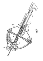
FIG. 6 is a perspective view of a cocked crossbow and the apparatus shown in FIG. 1.
FIG. 7; is a perspective view of the apparatus shown in FIG. 1 in the process of de-cocking the crossbow shown in FIG. 6;
FIG. 8 is a perspective view of the apparatus shown in FIG. 1 being removed from the crossbow shown in FIG. 6 after de-cocking the crossbow;
FIG. 9 is a side view of the joint of a jointed wedge of the instant invention;
FIG. 10 is a side view of the wedge shown in FIG. 9 un-jointed;
FIG. 11 is a perspective view of an the central portion of an alternative wedge of the instant invention in the form of a tapered rod; and
FIG. 12 is a perspective view of another preferred apparatus of the instant invention for de-cocking a reverse draw crossbow.
DETAILED DESCRIPTION OF THE INVENTION
Referring now to FIG. 1, therein is shown an perspective view of a preferred apparatus 10 of the instant invention for de-cocking a crossbow, the apparatus 10 including body 11 and wedge 14. Body 11 is adapted to attach to a crossbow as will be detailed below. Referring now to FIG. 2, therein is shown a perspective view of the underside of body 11. It will be noted that wedge 14 has been passed through (engaged with) a channel in body 11. Body 11 also comprises U-bolt 12 welded to plate 12 a. U-bolt 12 welded to plate 12 a so that the spaced apart legs of U-bolt 12 are parallel to each other and extend from body 11. The legs of U-bolt 12 are covered with plastic coating 18. Referring again to FIG. 1, plate 12 a is attached to body 11 by round head bolts 19 and 20. Plate 12 a can be re-positioned toward handle 13 by re-attaching plate 12 a to body 11 using round head bolts 20 and 21 to adapt apparatus 10 to a wider range of different crossbows. Apparatus 10 comprises handle 13. Referring now to FIG. 4, handle 13 comprises a threaded stud 13 a. A section of brass rod 13 b is inserted into stud 13 a so that rod 13 b extends from stud 13 a as shown in FIG. 4. Referring again to FIG. 1, threaded stud 13 a is screwed into a threaded bore in body 11 which threaded bore intersects with the channel in the body so that when wedge 14 is slid through said channel the brass distal end of stud 13 a can contact wedge 14 and halt further travel of wedge 14 through body 11. In use, the friction qualities of brass on the wedge at the top of the wedge 14, the friction qualities of the plastic insert 11 b on the bottom of the wedge 14 and the friction qualities of the plastic inserts 11 a, 11 b and 11 c on the sides of wedge 14 are all highly preferred as resulting in the smooth progression of the wedge 14 through the channel as a crossbow is de-cocked. The distal end of wedge 14 near the wider portion of the wedge is notched with notch 17 to receive the bowstring of a crossbow. Pin 16 is positioned though the wedge as shown to help guide wedge 14 on the barrel of a crossbow. Ball 15 is attached to the other end of wedge 14 as a handle for the wedge 14. Referring again to FIG. 2, plastic inserts 11 b and 11 c are attached to body 11 by screws 11 d and 11 e. Plastic insert 11 a is attached to body 11 by bolt 19.
The preferred material of construction for the body 11, the plate 12 a and the U-bolt 12 is steel coated with zinc and/or a paint coating. However, apparatus 10 could, of course, be made of any suitable material and could even be made by injection molding a thermoplastic polymer. The preferred material of construction for the handle 13 and ball 15 is plastic. The preferred material of construction for the wedge 14 is zinc coated steel. Pin 16 is preferably a steel roll pin. Thin plastic tubing (not shown) is preferably slipped onto the exposed ends of pin 16. Although U-bolt 12 and plate 12 a are preferred as a means of attaching body 11 to a crossbow, body 11 can be attached to a crossbow by any suitable means such as bolts, clamps, screws, sockets, hooks (as shown in FIG. 12) or pins. The legs of U-bolt 12 are preferably not threaded.
Referring now to FIG. 3D, therein is shown a perspective view of plastic insert 11 b including holes 11 j and 11 k for the passage of screws 11 d and 11 e. Referring now to FIG. 3A, therein is shown a perspective view of plastic insert 11 a including threaded hole 11 i for bolt 19. Referring now to FIG. 3B and FIG. 3C, therein is shown top and bottom perspective views of plastic insert 11 c including bore 13 b. The diameter of bore 13 b being somewhat larger than the diameter of threaded stud 13 a so that threaded stud 13 a can intersect with the channel through which the wedge of the instant invention is slid, which channel is defined in this embodiment by the slot in insert 11 c and the exposed surface of insert 11 b. Pilot holes 11 f and 11 g are provided to receive screws 11 d and 11 e.
Referring now to FIG. 5, therein is shown wedge 14 which is preferably about two feet long and 3/16 inch thick. Hole 14 a is provided to attach an accessory. It will be noted that wedge 14 is somewhat asymmetrical about the longitudinal axis of the wedge from the notch 17 to the other end of wedge 14 so that wedge 14 can be inverted in body 11 to better adapt apparatus 10 to different crossbows.
Referring now to FIG. 6, therein is shown a perspective view of a cocked crossbow 22 and the apparatus 10 shown in FIG. 1. Crossbow 22 includes bowstring 23 and trigger 24. In use, apparatus 10 is attached to cocked crossbow 22 with the bowstring of the crossbow placed in the notch 17 of wedge 14 with the legs of U-bolt 12 resting against crossbow 22 as shown in FIG. 7. Threaded stud 13 a of handle 13 is screwed into body 11 to contact wedge 14. The safety of crossbow 22 is switched off and trigger 24 pulled to release the bowstring 23 of crossbow 22. Bowstring 23 of crossbow 22 trys to pass wedge 14 through the channel in body 11 but passage of wedge 14 through the channel is stopped by contact with threaded stud 13 a of handle 13. Then, as shown in FIG. 7, handle 13 is unscrewed to permit the controlled passage of wedge 14 through the channel in body 11. When crossbow 22 has been fully de-cocked, apparatus 10 is removed from crossbow 22 as shown in FIG. 8.
Referring now to FIG. 12, therein is shown an perspective view of a preferred apparatus 25 of the instant invention for de-cocking a reverse draw crossbow, the apparatus 25 being the same in many respects to the apparatus 10 shown in FIG. 1. Elements that are the same in apparatus 25 as apparatus 10 have the same reference numerals as the apparatus 10 shown in FIG. 1. The different element in apparatus 25 is hook 26 welded to plate 12 a. Hook 26 has hook ends 27 and 28. Apparatus 25 is attached to a reverse draw crossbow by placing a pin transversely through the barrel of the crossbow to engage with the hook ends 27 and 28.
In a highly preferred embodiment, the wedge of the instant invention is jointed. Referring now to FIG. 9, therein is shown a side view of the central portion of such a jointed wedge. Ball end portion 100 b of the wedge is held to notch portion 100 a of wedge by button magnet 100 c. Aperture 100 g through wedge portion 100 a is coincident with bore 100 h, leaving ledge 100 i in wedge portion 100 a. Button magnet 100 d is provided as a spare. When a button magnet is placed in bore 100 h, the magnet rests on ledge 100 i, which button magnet can be removed by finger pressure from the back side of wedge portion 100 a. Referring now to FIG. 10, therein is shown notch end portion 100 a separated from ball end portion 100 b. Pin 100 e is dimensioned to fit into bore 100 j. Pin 100 f is dimensioned to fit into bore 100 k. In FIG. 10, button magnet 100 c is shown placed in bore 100 h of notch end portion 100 a.
The term “wedge” used herein is intended to be defined broadly as an elongated body comprising opposed sides that taper or incline from one end thereof to the other end thereof and thus the term “wedge” includes, for example, a tapered rod. FIG. 11 shows the central portion of a wedge of the instant invention in the form of tapered rod 110. Wedge 14 of FIG. 1 is in example of a wedge having opposed inclined planar surfaces from accessory hole 14 a to ball 15 and parallel planar surfaces perpendicular to the opposed inclined planar surfaces. Although not preferred, wedge 14 could have had rounded opposed inclined surfaces from accessory hole 14 a to ball 15 and parallel planar surfaces perpendicular to the opposed inclined rounded surfaces.
In conclusion, while the instant invention has been described above according to its preferred embodiment, it can be modified within the spirit and scope of this disclosure. This application is therefore intended to cover any variations, uses, or adaptations of the instant invention using the general principles disclosed herein. Further, the instant application is intended to cover such departures from the present disclosure as come within the known or customary practice in the art to which this invention pertains.

Claims (16)

What is claimed is:
1. Apparatus for de-cocking a crossbow, the crossbow having a bowstring and a trigger comprising: (a) a first body adapted to attach to a crossbow, the first body comprising a channel therethrough, the first body also comprising a threaded bore therethrough, the threaded bore intersecting with the channel; (b) an elongated second body having opposed sides that incline once from one end thereof toward the other end thereof, the elongated second body having a notch at the other end thereof, the elongated second body adapted to slide through said channel, (c) a threaded stud having a distal end so that when said elongated second body is slid through said channel and said threaded stud is threaded into said threaded bore, the distal end of said stud can contact said elongated second body and halt further travel of said elongated second body through said first body, so that when the first body is attached to a cocked crossbow with the bowstring of the crossbow positioned in the notch of the elongated second body with the distal end of the stud contacting the elongated second body, the trigger of the crossbow can then be pulled to release the bowstring against the elongated second body and then the threaded stud can be unscrewed to permit the elongated second body to controllably slide further through said channel to de-cock the crossbow.
2. The apparatus of claim 1, wherein the first body comprises spaced apart parallel extensions from the first body so that when the trigger of a crossbow is pulled to release the bowstring against the elongated second body, the parallel spaced apart parallel extensions from the first body attach the first body to the crossbow.
3. The apparatus of claim 2, wherein the elongated second body comprises opposed inclined planar surfaces.
4. The apparatus of claim 3, wherein the elongated second body is comprised of jointed sections.
5. The apparatus of claim 2, wherein the elongated second body comprises opposed inclined curved surfaces.
6. The apparatus of claim 5, wherein the elongated second body comprises a tapered rod.
7. The apparatus of claim 1, wherein the first body comprises spaced apart hook extensions from the first body so that when the trigger of a crossbow is pulled to release the bowstring against the elongated second body, the parallel spaced apart parallel hook extensions from the first body attach the first body to the crossbow.
8. The apparatus of claim 7, wherein the elongated second body comprises opposed inclined planar surfaces.
9. The apparatus of claim 8, wherein the elongated second body is comprised of jointed sections.
10. The apparatus of claim 7, wherein the elongated second body comprises opposed inclined curved surfaces.
11. The apparatus of claim 10, wherein the elongated second body comprises a tapered rod.
12. The apparatus of claim 1, wherein the elongated second body comprises opposed inclined planar surfaces.
13. The apparatus of claim 12, wherein the elongated second body is comprised of jointed sections.
14. The apparatus of claim 1, wherein the elongated second body comprises opposed inclined curved surfaces.
15. The apparatus of claim 14, wherein the elongated second body comprises a tapered rod.
16. A method of de-cocking a cocked crossbow, the crossbow having a bowstring, the method comprising the use of an elongated second body having opposed sides that incline once from one end thereof toward the other end thereof, the elongated second body having a notch at the other end thereof, comprising: (a) engaging the bowstring of a crossbow with a said notch of the elongated second body, the elongated second body being engaged in a channel of a first body, the first body comprising a threaded bore intersecting with said channel, a threaded stud being screwed into said threaded bore so that the end of said stud contacts said elongated second body in said channel; (b) attaching said first body to said cocked crossbow; (c) releasing said bowstring against said notch; and (d) unscrewing said stud to permit said elongated second body to controllably slide further through said channel to de-cock said crossbow.
US14/999,459 2015-05-18 2016-05-09 Crossbow de-cocking device and method Expired - Fee Related US9494381B1 (en)

Priority Applications (1)

Application Number Priority Date Filing Date Title
US14/999,459 US9494381B1 (en) 2015-05-18 2016-05-09 Crossbow de-cocking device and method

Applications Claiming Priority (2)

Application Number Priority Date Filing Date Title
US201562179785P 2015-05-18 2015-05-18
US14/999,459 US9494381B1 (en) 2015-05-18 2016-05-09 Crossbow de-cocking device and method

Publications (2)

Publication Number Publication Date
US9494381B1 true US9494381B1 (en) 2016-11-15
US20160341513A1 US20160341513A1 (en) 2016-11-24

Family

ID=57234991

Family Applications (1)

Application Number Title Priority Date Filing Date
US14/999,459 Expired - Fee Related US9494381B1 (en) 2015-05-18 2016-05-09 Crossbow de-cocking device and method

Country Status (1)

Country Link
US (1) US9494381B1 (en)

Cited By (5)

* Cited by examiner, † Cited by third party
Publication number Priority date Publication date Assignee Title
US20190186865A1 (en) * 2013-03-13 2019-06-20 Ravin Crossbows, Llc Crossbow
US10458743B1 (en) * 2017-06-09 2019-10-29 James J. Kempf Crossbow with built in cocking device
US11002505B1 (en) * 2019-12-17 2021-05-11 Hunter's Manufacturing Co, , Inc. De-cock mechanism for a crossbow
US11221191B2 (en) 2020-05-08 2022-01-11 Hunter's Manufacturing Company, Inc. Crossbow with winch
US11713941B1 (en) * 2022-05-06 2023-08-01 Crist Reed Inc. Cocking mechanisms for a crossbow

Citations (18)

* Cited by examiner, † Cited by third party
Publication number Priority date Publication date Assignee Title
US3670711A (en) * 1971-02-22 1972-06-20 Max Firestone Crossbow cocking device
US4603676A (en) * 1984-04-17 1986-08-05 Luoma Eugene H Bow drawback mechanism
US4919107A (en) * 1988-06-27 1990-04-24 Walter A. Bunts Equalized force shooter for a bow and arrow
US5220906A (en) * 1991-01-08 1993-06-22 Horton Manufacturing Company Inc. Device to draw the bowstring of a crossbow
US5823172A (en) * 1995-09-25 1998-10-20 Suggitt; Jack A. Crossbow bow string drawing device
US6012440A (en) * 1995-05-25 2000-01-11 Grindle; Joseph Gary Brace for an archery bow
US6286496B1 (en) * 1998-01-08 2001-09-11 William J. Bednar Crossbow bowstring drawing mechanism
US6499478B1 (en) * 2001-06-18 2002-12-31 Anita J. Perez Apparatus for preventing damage to bows
US6799566B1 (en) * 2000-05-30 2004-10-05 Ermanno Malucelli Automatic cocking device in a crossbow for hunting and archery
US7017568B1 (en) * 2003-05-06 2006-03-28 Douglas Lane Smith Pneumatic cocking device
US20120152220A1 (en) * 2010-12-14 2012-06-21 Falcon Outdoors, Llc Device for decocking a crossbow
US8375928B1 (en) 2010-06-11 2013-02-19 Hunter's Manufacturing Company, Inc. Slip clutch
US8376882B2 (en) * 2008-08-07 2013-02-19 Hunter's Manufacturing Company, Inc. Unloading bolt
US8439026B1 (en) * 2012-01-17 2013-05-14 Frederick R. Kilian Mechanical full draw, hold, lock and arrow release device for compound bows
US8671923B2 (en) * 2010-06-15 2014-03-18 Jerry Goff Stock and trigger assembly for crossbow
US20140261360A1 (en) * 2013-03-13 2014-09-18 Field Logic, Inc. De-cocking mechanism for a bow
US20140305417A1 (en) 2010-12-14 2014-10-16 Archery America, L.L.C. Crossbow With Integrated Decocking Device
US9341432B1 (en) * 2014-10-29 2016-05-17 Clem Wohleb Drawstring cocking assembly

Patent Citations (21)

* Cited by examiner, † Cited by third party
Publication number Priority date Publication date Assignee Title
US3670711A (en) * 1971-02-22 1972-06-20 Max Firestone Crossbow cocking device
US4603676A (en) * 1984-04-17 1986-08-05 Luoma Eugene H Bow drawback mechanism
US4919107A (en) * 1988-06-27 1990-04-24 Walter A. Bunts Equalized force shooter for a bow and arrow
US5220906A (en) * 1991-01-08 1993-06-22 Horton Manufacturing Company Inc. Device to draw the bowstring of a crossbow
US6012440A (en) * 1995-05-25 2000-01-11 Grindle; Joseph Gary Brace for an archery bow
US5823172A (en) * 1995-09-25 1998-10-20 Suggitt; Jack A. Crossbow bow string drawing device
US6286496B1 (en) * 1998-01-08 2001-09-11 William J. Bednar Crossbow bowstring drawing mechanism
US6799566B1 (en) * 2000-05-30 2004-10-05 Ermanno Malucelli Automatic cocking device in a crossbow for hunting and archery
US6499478B1 (en) * 2001-06-18 2002-12-31 Anita J. Perez Apparatus for preventing damage to bows
US7017568B1 (en) * 2003-05-06 2006-03-28 Douglas Lane Smith Pneumatic cocking device
US8376882B2 (en) * 2008-08-07 2013-02-19 Hunter's Manufacturing Company, Inc. Unloading bolt
US8578917B2 (en) 2010-06-11 2013-11-12 Hunter's Manufacturing Company, Inc. Slip clutch
US8375928B1 (en) 2010-06-11 2013-02-19 Hunter's Manufacturing Company, Inc. Slip clutch
US8671923B2 (en) * 2010-06-15 2014-03-18 Jerry Goff Stock and trigger assembly for crossbow
US20120152220A1 (en) * 2010-12-14 2012-06-21 Falcon Outdoors, Llc Device for decocking a crossbow
US8752535B2 (en) * 2010-12-14 2014-06-17 Archery America, L.L.C. Device for decocking a crossbow
US20140305417A1 (en) 2010-12-14 2014-10-16 Archery America, L.L.C. Crossbow With Integrated Decocking Device
US9303944B2 (en) * 2010-12-14 2016-04-05 Archery America, L.L.C. Crossbow with integrated decocking device
US8439026B1 (en) * 2012-01-17 2013-05-14 Frederick R. Kilian Mechanical full draw, hold, lock and arrow release device for compound bows
US20140261360A1 (en) * 2013-03-13 2014-09-18 Field Logic, Inc. De-cocking mechanism for a bow
US9341432B1 (en) * 2014-10-29 2016-05-17 Clem Wohleb Drawstring cocking assembly

Cited By (15)

* Cited by examiner, † Cited by third party
Publication number Priority date Publication date Assignee Title
US20190186865A1 (en) * 2013-03-13 2019-06-20 Ravin Crossbows, Llc Crossbow
US10458743B1 (en) * 2017-06-09 2019-10-29 James J. Kempf Crossbow with built in cocking device
US20220214133A1 (en) * 2019-12-17 2022-07-07 Hunter's Manufacturing Company, Inc. D/B/A Tenpoint Crossbow Technologies De-cock mechanism for a crossbow
US11009310B1 (en) * 2019-12-17 2021-05-18 Hunter's Manufacturing Co., Inc. Reset mechanism for a crossbow
US11306994B2 (en) * 2019-12-17 2022-04-19 Hunter's Manufacturing Company, Inc. Reset mechanism for a crossbow
US11002505B1 (en) * 2019-12-17 2021-05-11 Hunter's Manufacturing Co, , Inc. De-cock mechanism for a crossbow
US11428499B2 (en) * 2019-12-17 2022-08-30 Hunter's Manufacturing Company, Inc. De-cock mechanism for a crossbow
US11592258B2 (en) * 2019-12-17 2023-02-28 Hunter's Manufacturing Company, Inc. De-cock mechanism for a crossbow
US11885587B2 (en) * 2019-12-17 2024-01-30 Hunter's Manufacturing Company, Inc. Reset mechanism for a bow
US11221191B2 (en) 2020-05-08 2022-01-11 Hunter's Manufacturing Company, Inc. Crossbow with winch
US11236963B2 (en) * 2020-05-08 2022-02-01 Hunter's Manufacturing Company, Inc. Crossbow with cocking mechanism
US11236964B2 (en) * 2020-05-08 2022-02-01 Hunter's Manufacturing Company, Inc. Crossbow with de-cocking mechanism
US20220138018A1 (en) * 2020-05-08 2022-05-05 Hunter's Manufacturing Company, Inc. D/B/A Tenpoint Crossbow Technologies Crossbow de-cocking mechanism
US11913752B2 (en) * 2020-05-08 2024-02-27 Hunter's Manufacturing Company, Inc. Crossbow de-cocking mechanism
US11713941B1 (en) * 2022-05-06 2023-08-01 Crist Reed Inc. Cocking mechanisms for a crossbow

Also Published As

Publication number Publication date
US20160341513A1 (en) 2016-11-24

Similar Documents

Publication Publication Date Title
US9494381B1 (en) Crossbow de-cocking device and method
US5619801A (en) Fiber optic pin sight for a bow
US8499753B2 (en) Integrated cocking device
US9314013B2 (en) Tote for dragging taken game
US9261318B2 (en) Firearm accessory mounting assembly
CA3048251C (en) Crossbow with detachable limb assembly
EP2078916A3 (en) Takedown rifle
US9707385B1 (en) Tattoo needle tube and grip adapter
US20200362632A1 (en) Simply Smart Ladder Clamp
ATE389510T1 (en) TOOL WITH QUICK CLAMPING DEVICE
US3407799A (en) Archery bow and handgrip alignment apparatus therefor
US4542731A (en) Bow with vertically and horizontally adjustable arrow support
US10429147B2 (en) Portable shooting stabilization assist clamp
US20190011213A1 (en) Crossbow barrel
US10571214B2 (en) Crossbow track assembly
US20070163558A1 (en) Wood spear gun having a magnet under the spear track
US20160069632A1 (en) Portable Shooting Stabilization Assist Clamp
US20170095916A1 (en) Muzzle suitable for holding nail clamps
US10175025B1 (en) Crossbow cocking apparatus
US7927172B1 (en) Game call holder
KR101311614B1 (en) Birdgun with elastic cord
US4125927A (en) Embedded arrowhead retrieving and multipurpose tool
US2954765A (en) Archer's arm
US20150184975A1 (en) Rope locking device
US6925996B1 (en) Bowstring release device with string loop and built-in nock receiver

Legal Events

Date Code Title Description
STCF Information on status: patent grant

Free format text: PATENTED CASE

AS Assignment

Owner name: OLIVER'S LLC, MICHIGAN

Free format text: ASSIGNMENT OF ASSIGNORS INTEREST;ASSIGNOR:JESKE, RICHARD HENRY;REEL/FRAME:050380/0254

Effective date: 20190909

FEPP Fee payment procedure

Free format text: MAINTENANCE FEE REMINDER MAILED (ORIGINAL EVENT CODE: REM.); ENTITY STATUS OF PATENT OWNER: SMALL ENTITY

LAPS Lapse for failure to pay maintenance fees

Free format text: PATENT EXPIRED FOR FAILURE TO PAY MAINTENANCE FEES (ORIGINAL EVENT CODE: EXP.); ENTITY STATUS OF PATENT OWNER: SMALL ENTITY

STCH Information on status: patent discontinuation

Free format text: PATENT EXPIRED DUE TO NONPAYMENT OF MAINTENANCE FEES UNDER 37 CFR 1.362

FP Expired due to failure to pay maintenance fee

Effective date: 20201115