US9500817B2 - Connectors and adapters with auto-latching features - Google Patents
Connectors and adapters with auto-latching features Download PDFInfo
- Publication number
- US9500817B2 US9500817B2 US14/745,571 US201514745571A US9500817B2 US 9500817 B2 US9500817 B2 US 9500817B2 US 201514745571 A US201514745571 A US 201514745571A US 9500817 B2 US9500817 B2 US 9500817B2
- Authority
- US
- United States
- Prior art keywords
- connector
- latch arm
- plug
- adapter
- plug body
- Prior art date
- Legal status (The legal status is an assumption and is not a legal conclusion. Google has not performed a legal analysis and makes no representation as to the accuracy of the status listed.)
- Active
Links
Images


Classifications
-
- G—PHYSICS
- G02—OPTICS
- G02B—OPTICAL ELEMENTS, SYSTEMS OR APPARATUS
- G02B6/00—Light guides; Structural details of arrangements comprising light guides and other optical elements, e.g. couplings
- G02B6/24—Coupling light guides
- G02B6/36—Mechanical coupling means
- G02B6/38—Mechanical coupling means having fibre to fibre mating means
- G02B6/3807—Dismountable connectors, i.e. comprising plugs
- G02B6/389—Dismountable connectors, i.e. comprising plugs characterised by the method of fastening connecting plugs and sockets, e.g. screw- or nut-lock, snap-in, bayonet type
-
- G—PHYSICS
- G02—OPTICS
- G02B—OPTICAL ELEMENTS, SYSTEMS OR APPARATUS
- G02B6/00—Light guides; Structural details of arrangements comprising light guides and other optical elements, e.g. couplings
- G02B6/24—Coupling light guides
- G02B6/36—Mechanical coupling means
-
- G—PHYSICS
- G02—OPTICS
- G02B—OPTICAL ELEMENTS, SYSTEMS OR APPARATUS
- G02B6/00—Light guides; Structural details of arrangements comprising light guides and other optical elements, e.g. couplings
- G02B6/24—Coupling light guides
- G02B6/36—Mechanical coupling means
- G02B6/38—Mechanical coupling means having fibre to fibre mating means
- G02B6/3807—Dismountable connectors, i.e. comprising plugs
- G02B6/3869—Mounting ferrules to connector body, i.e. plugs
- G02B6/387—Connector plugs comprising two complementary members, e.g. shells, caps, covers, locked together
-
- G—PHYSICS
- G02—OPTICS
- G02B—OPTICAL ELEMENTS, SYSTEMS OR APPARATUS
- G02B6/00—Light guides; Structural details of arrangements comprising light guides and other optical elements, e.g. couplings
- G02B6/24—Coupling light guides
- G02B6/36—Mechanical coupling means
- G02B6/38—Mechanical coupling means having fibre to fibre mating means
- G02B6/3807—Dismountable connectors, i.e. comprising plugs
- G02B6/3895—Dismountable connectors, i.e. comprising plugs identification of connection, e.g. right plug to the right socket or full engagement of the mating parts
-
- H—ELECTRICITY
- H01—ELECTRIC ELEMENTS
- H01R—ELECTRICALLY-CONDUCTIVE CONNECTIONS; STRUCTURAL ASSOCIATIONS OF A PLURALITY OF MUTUALLY-INSULATED ELECTRICAL CONNECTING ELEMENTS; COUPLING DEVICES; CURRENT COLLECTORS
- H01R13/00—Details of coupling devices of the kinds covered by groups H01R12/70 or H01R24/00 - H01R33/00
- H01R13/62—Means for facilitating engagement or disengagement of coupling parts or for holding them in engagement
- H01R13/6205—Two-part coupling devices held in engagement by a magnet
-
- H—ELECTRICITY
- H01—ELECTRIC ELEMENTS
- H01R—ELECTRICALLY-CONDUCTIVE CONNECTIONS; STRUCTURAL ASSOCIATIONS OF A PLURALITY OF MUTUALLY-INSULATED ELECTRICAL CONNECTING ELEMENTS; COUPLING DEVICES; CURRENT COLLECTORS
- H01R13/00—Details of coupling devices of the kinds covered by groups H01R12/70 or H01R24/00 - H01R33/00
- H01R13/62—Means for facilitating engagement or disengagement of coupling parts or for holding them in engagement
- H01R13/627—Snap or like fastening
- H01R13/6275—Latching arms not integral with the housing
-
- H—ELECTRICITY
- H01—ELECTRIC ELEMENTS
- H01R—ELECTRICALLY-CONDUCTIVE CONNECTIONS; STRUCTURAL ASSOCIATIONS OF A PLURALITY OF MUTUALLY-INSULATED ELECTRICAL CONNECTING ELEMENTS; COUPLING DEVICES; CURRENT COLLECTORS
- H01R13/00—Details of coupling devices of the kinds covered by groups H01R12/70 or H01R24/00 - H01R33/00
- H01R13/66—Structural association with built-in electrical component
- H01R13/665—Structural association with built-in electrical component with built-in electronic circuit
-
- G—PHYSICS
- G02—OPTICS
- G02B—OPTICAL ELEMENTS, SYSTEMS OR APPARATUS
- G02B6/00—Light guides; Structural details of arrangements comprising light guides and other optical elements, e.g. couplings
- G02B6/24—Coupling light guides
- G02B6/36—Mechanical coupling means
- G02B6/38—Mechanical coupling means having fibre to fibre mating means
- G02B6/3807—Dismountable connectors, i.e. comprising plugs
- G02B6/381—Dismountable connectors, i.e. comprising plugs of the ferrule type, e.g. fibre ends embedded in ferrules, connecting a pair of fibres
- G02B6/3825—Dismountable connectors, i.e. comprising plugs of the ferrule type, e.g. fibre ends embedded in ferrules, connecting a pair of fibres with an intermediate part, e.g. adapter, receptacle, linking two plugs
-
- G—PHYSICS
- G02—OPTICS
- G02B—OPTICAL ELEMENTS, SYSTEMS OR APPARATUS
- G02B6/00—Light guides; Structural details of arrangements comprising light guides and other optical elements, e.g. couplings
- G02B6/24—Coupling light guides
- G02B6/36—Mechanical coupling means
- G02B6/38—Mechanical coupling means having fibre to fibre mating means
- G02B6/3807—Dismountable connectors, i.e. comprising plugs
- G02B6/389—Dismountable connectors, i.e. comprising plugs characterised by the method of fastening connecting plugs and sockets, e.g. screw- or nut-lock, snap-in, bayonet type
- G02B6/3893—Push-pull type, e.g. snap-in, push-on
-
- G—PHYSICS
- G02—OPTICS
- G02B—OPTICAL ELEMENTS, SYSTEMS OR APPARATUS
- G02B6/00—Light guides; Structural details of arrangements comprising light guides and other optical elements, e.g. couplings
- G02B6/24—Coupling light guides
- G02B6/36—Mechanical coupling means
- G02B6/38—Mechanical coupling means having fibre to fibre mating means
- G02B6/3807—Dismountable connectors, i.e. comprising plugs
- G02B6/3898—Tools, e.g. handheld; Tuning wrenches; Jigs used with connectors, e.g. for extracting, removing or inserting in a panel, for engaging or coupling connectors, for assembling or disassembling components within the connector, for applying clips to hold two connectors together or for crimping
-
- H—ELECTRICITY
- H04—ELECTRIC COMMUNICATION TECHNIQUE
- H04Q—SELECTING
- H04Q1/00—Details of selecting apparatus or arrangements
- H04Q1/02—Constructional details
- H04Q1/13—Patch panels for monitoring, interconnecting or testing circuits, e.g. patch bay, patch field or jack field; Patching modules
- H04Q1/135—Patch panels for monitoring, interconnecting or testing circuits, e.g. patch bay, patch field or jack field; Patching modules characterized by patch cord details
- H04Q1/136—Patch panels for monitoring, interconnecting or testing circuits, e.g. patch bay, patch field or jack field; Patching modules characterized by patch cord details having patch field management or physical layer management arrangements
Definitions
- a variety of communications devices can be used for switching, cross-connecting, and interconnecting communications signal transmission paths in a communications network.
- Some such communications devices are installed in one or more equipment racks to permit organized, high-density installations to be achieved in limited space available for equipment.
- Some connections are made between plug connectors (e.g., optical plug connectors, electrical plug connectors, etc.) and adapters (e.g., optical adapters, electrical jacks, etc.) within the communications network.
- FIG. 23 is a cross-sectional view of one example optical adapter 450 defining front and rear ports 452 receiving first and second optical plug connectors 400 A, 400 B, respectively.
- Each optical plug connector 400 A, 400 B includes a manually actuated latch finger 405 that extends rearwardly so that a distal end of the latch finger 405 is located at a first distance L′′ away from the front of the connector 400 .
- the first distance L′′ is sufficiently long that at least the distal end of the latch finger 405 extends outwardly from the optical adapter 450 when the connector 400 is fully inserted within the adapter 450 . Accordingly, the distal end of the latch finger 405 is accessible to a user when the connector 400 is fully inserted within the adapter 450 .
- the latch finger 405 defines latching surfaces that engage abutment surfaces within the ports 452 .
- the latch finger 405 may be flexed towards a body of the connector 400 (e.g., by a finger of the user or by the adapter body as the user applies an insertion force to the connector 400 ) to allow the latching surfaces to pass the abutment surfaces.
- the latch finger 405 flexes back to align the latching surfaces and the abutment surfaces, thereby securing the connector 400 to the adapter 450 .
- the latch finger 405 is depressed by a user (e.g., using a finger of the user) to move the latching surface out of engagement with the abutment surface.
- a user e.g., using a finger of the user
- the latching surface is clear of the abutment surface, the user may pull the connector 400 out of the adapter port 452 .
- Manually actuated latch fingers can be actuated accidentally by a user (e.g., when routing cables past a dense group of ports; when actuating an adjacent latch finger; etc.). Improvements in connection of fiber optic connectors are desired.
- a plug connector e.g., a fiber optic connector, an electrical connector, etc.
- a latching arrangement including a latch arm pivotally coupled to the plug body.
- the latch arm is pivotal between a raised position and a lowered position.
- the latch arm is configured to be in the lowered position absent an external force.
- the latch arm is at least partially formed from or coated with a material that is temporarily magnetizable.
- the adapter arrangement includes an adapter body defining a port and a magnet arrangement coupled to the adapter body.
- the magnet arrangement includes at least one permanent magnet and at least one electromagnet.
- the permanent magnet constantly generates a magnetic field within a region of the port.
- the electromagnet is configured to selectively generate a magnetic field within the port. The electromagnet is stronger than the permanent magnet.
- a managed connectivity system including at least one adapter defining a plurality of ports having magnet arrangements; a plug connector including a magnetizable latching arm that is sufficiently short to not extend outside of the adapter when the plug connector is mounted within one of the ports of the adapter; and a management system including a processor that is configured to operate the magnet arrangements.
- the latching arm is moveable between a lowered position and a raised position.
- the latching arm is sized to pass by the abutment surface when in the lowered position during insertion or removal of the plug connector.
- the latching arm is sized to engage the abutment surface when the in the raised position during insertion or removal of the plug connector.
- a plug connector e.g., an optical plug connector, an electrical plug connector, etc.
- an adapter including determining that a plug connector has been inserted into the port of the adapter; determining that insertion of the plug connector is authorized at the port; and actuating an electromagnet to generate a magnetic field that is sufficiently powerful to lift a latch arm of the plug connector to a raised position.
- the plug connector is not secured to the adapter until the electromagnet is actuated.
- the plug connector has a latch arm that is retained in a raised position by a magnetic field having a first polarity.
- the method includes receiving a port selection identifying a port of an adapter from which removal of the plug connector is desired; receiving a readiness indication from a user; actuating a magnet arrangement; and indicating to the user that the plug connector is unlatched and ready for removal. Actuating the magnet arrangement generates a magnetic field having a second polarity that is opposite the first polarity that moves the latch arm of the plug connector to a lowered position.
- inventive aspects can relate to individual features and combinations of features. It is to be understood that both the foregoing general description and the following detailed description are exemplary and explanatory only and are not restrictive of the broad inventive concepts upon which the embodiments disclosed herein are based.
- FIG. 1 is a front perspective view of an example fiber optic connector including a latching arrangement having features that are examples of inventive aspects in accordance with the principles of the present disclosure
- FIG. 2 is an enlarged, front perspective view of a plug nose portion of the connector of FIG. 1 shown with the latching arrangement in a lowered position;
- FIG. 3 is a rear perspective view of the plug nose portion of FIG. 2 ;
- FIG. 4 is a side elevational view of the plug nose portion of FIG. 2 ;
- FIG. 5 is a top plan view of the plug nose portion of FIG. 2 ;
- FIG. 6 is an enlarged, front perspective view of a plug nose portion of the connector of FIG. 1 shown with the latching arrangement in a raised position;
- FIG. 7 is a rear perspective view of the plug nose portion of FIG. 6 ;
- FIG. 8 is a side elevational view of the plug nose portion of FIG. 6 ;
- FIG. 9 is a rear perspective view of another example plug nose having another example latching arrangement exploded outwardly from the plug nose;
- FIG. 10 is a side elevational view of the plug nose portion of FIG. 9 with the latching arrangement assembled and in a raised position;
- FIG. 11 is an enlarged view of a portion of another plug nose portion having another latching arrangement in the raised position
- FIG. 12 is a front perspective view of an optical adapter defining ports for receiving a fiber optic connector
- FIG. 13 is a cross-sectional view taken along a plug insertion axis of the optical adapter of FIG. 12 and a connector having one of the latching arrangements disclosed herein aligned for insertion into one of the ports of the optical adapter;
- FIG. 14 shows the connector of FIG. 13 partially inserted within the optical connector
- FIG. 15 shows the connector of FIG. 13 fully inserted within the optical connector and the latching arrangement in the raised position
- FIG. 16 is a schematic block diagram of an example management system that is operationally coupled to equipment including one or more optical adapters that are configured in accordance with the principles of the present disclosure
- FIG. 17 is a flowchart illustrating an insertion process by which a user may securely plug a connector into an optical adapter
- FIG. 18 is a flowchart illustrating an insertion authorization process by which the management system may decide whether or not to latch a connector within an optical adapter
- FIG. 19 is a flowchart illustrating a removal process by which a user may remove a connector from an optical adapter
- FIG. 20 is a flowchart illustrating a removal authorization process by which the management system may decide whether or not to unlatch a connector within an optical adapter
- FIG. 21 is a cross-sectional view taken along a plug insertion axis of an optical adapter including an ejector for pushing a connector out of the adapter port;
- FIG. 22 is a cross-sectional view taken along a plug insertion axis of an optical adapter including an internal micro-switch by which a user may indicate readiness to remove a connector by pushing the connector further into the adapter port;
- FIG. 23 illustrates an adapter receiving connectors having manually operated latching arrangements that protrude from the adapter ports
- FIG. 24 is a front perspective view of a connector body with another example implementation of a latching member exploded outwardly from the connector body;
- FIG. 25 shows the latching member of FIG. 24 assembled on the connector body
- FIG. 26 is a front perspective view of a connector body with another example implementation of a latching member exploded outwardly from the connector body;
- FIG. 27 shows the latching member of FIG. 26 assembled on the connector body
- FIG. 28 is a cross-sectional view of an adapter at which the connector body and latching member of FIG. 27 is inserted with the latching member disposed in the lowered position;
- FIG. 29 shows the adapter and connector of FIG. 28 with the latching member disposed in the raised position
- FIG. 30 is a front perspective view of a connector body with another example implementation of a latching member exploded outwardly from the connector body;
- FIG. 31 shows the latching member of FIG. 30 assembled on the connector body
- FIG. 32 is a cross-sectional view of an adapter at which the connector body and latching member of FIG. 31 is inserted with the latching member disposed in the lowered position;
- FIG. 33 shows the adapter and connector of FIG. 32 with the latching member disposed in the raised position.
- the present disclosure relates to plug connectors and adapters that may be automatically secured and released via a management system.
- Such automation may inhibit accidental and/or unauthorized insertion of plug connectors into adapter ports.
- the automation also may inhibit accidental and/or unauthorized removal of the plug connectors from the ports.
- the plug connectors are optical plug connectors (e.g., LC-type connectors, MPO-type connectors, SC-type connectors, LX.5-type connectors, etc.).
- the plug connectors are electrical plug connectors (e.g., RJ45-type plugs, RJpoint5-type plugs, etc.).
- RJ45-type plugs e.g., RJpoint5-type plugs, etc.
- the concepts disclosed herein may be applied to other types of plug connectors (e.g., MPO-type connectors, RJ45-type connectors, etc.) without deviating from the scope of the disclosure.
- FIG. 1 illustrates an example optical fiber connector 300 including a connector body 301 coupled to a ferrule 302 that is configured to hold at least one optical fiber.
- a boot 303 extends rearwardly from the connector body 301 to support and protect the optical fiber terminated by the connector 300 .
- the connector body 301 includes a key area 304 that protrudes upwardly from the connector body 301 .
- the key area 304 is configured to align with a notched area of an optical adapter port 352 (see FIG. 12 ) when the connector 300 is inserted into the optical adapter 350 .
- the example connector 300 includes a latching member 305 that is configured to pivot about a pivot axis P ( FIG. 7 ) between a raised position and a lowered position as will be discussed in more detail herein.
- the connector 300 includes a storage device 306 that is configured to electronically store information pertaining to the connector 300 (e.g., physical layer information).
- the storage device 306 is mounted to the key area 304 of the connector 300 .
- the connector 300 does not include memory for electronically storing information.
- FIGS. 2-8 illustrate one example latching member 305 suitable for use with the connector body 301 .
- FIGS. 2-5 show the latching member 305 in the lowered position relative to the connector body 301 and
- FIGS. 6-8 show the latching member 305 in the raised position.
- the latching member 305 When in the lowered position, the latching member 305 enables the connector 300 to be freely inserted and removed from an optical adapter port.
- the latching member 305 secures the connector 300 within an optical adapter port as will be disclosed in more detail herein.
- the latching member 305 includes a pivot pin 307 that pivotally couples to the connector body 301 .
- the pivot pin 307 is mounted within a recess 311 defined in the key area 304 of the connector body 301 .
- the pivot pin 307 is elongated along the pivot axis P and rotatable within the recess 311 .
- the pivot pin 307 is snap-fit between latching fingers 313 defined at a rear side of the key area 304 .
- the pivot pin 307 may be otherwise pivotally or rotatably coupled to the connector body 301 .
- An arm 308 extends from the pivot pin 307 to a handle 309 .
- the arm 308 is bent or curved.
- the arm 308 may define a planar surface.
- the handle 309 extends transverse to the arm 308 to form a T-shape.
- the handle 309 defines protrusions 310 that extend forwardly of the handle 309 towards the key region 304 at opposite sides of the handle 309 .
- the handle 309 has a generally rectangular shape.
- the latching member 305 extends rearwardly so that a distal end of the latch finger 405 is located at a second distance L′ away from the front of the connector 300 (see FIG. 4 ).
- the second distance L′ is less than the first distance L′′ of the conventional LC-type connector shown in FIG. 23 .
- the arm 308 is sufficiently short so that the distal end of the latching member 305 is fully contained within an adapter port 352 when the connector 300 is inserted within the adapter port 352 (see FIG. 15 ).
- FIGS. 9 and 10 show an alternative implementation of a connector body 301 ′ and a latching member 305 ′.
- the connector body 301 ′ includes two spaced apart support mounts 304 A extending from a rear side of a key area 304 ′.
- Each of the support mounts 304 A defines an opening 311 ′ through which a pivot pin 307 ′ may be inserted.
- the pivot pin 307 ′ may be snap-fit, welded, heat-sealed, or otherwise secured within the openings 311 ′.
- the pivot pin 307 ′ is rotationally fixed within the openings 311 ′.
- An example latching member 305 ′ includes a pin-receiving portion 315 that defines a channel sized and shaped to receive the pivot pin 307 ′.
- the pin-receiving portion 315 is configured to rotate around the pivot pin 307 ′ (see FIG. 10 ) to enable the latching member 305 ′ to pivot between the raised and lowered positions.
- the pin-receiving portion includes a hollow cylinder.
- the arm 308 extends from the pin-receiving portion 315 similar to how the arm 308 extends from the pivot pin 307 of latching member 305 .
- FIG. 11 illustrates yet another alternative implementation of a latching member 305 ′′ suitable for mounting on the connector body 301 ′ of FIGS. 9 and 10 .
- the latching member 305 ′′ is substantially similar to the latching member 305 ′ of FIGS. 9 and 10 , except that a pin-receiving portion 315 ′ includes a bent or folded section of the arm 308 .
- the pin-receiving portion 315 ′ is configured to rotate about the pivot pin 307 ′. However, the pin-receiving portion 315 ′ does not fully enclose the pivot pin 307 ′.
- any of the connector bodies 301 , 301 ′ shown above may include a bump 314 or other support structure that maintains the handle 309 of the latching member 305 , 305 ′, 305 ′′ at a first distance away from the connector body 301 , 301 ′ when the latching member 305 is in the lowered position.
- a bump 314 is shown on connector body 301 in FIGS. 3, 4, 7, and 8 .
- the arm 308 of the latching member 305 , 305 ′, 305 ′′ may seat on the bump 314 when the latching member 305 , 305 ′, 305 ′′ is in the lowered position.
- the latching member 305 , 305 ′, 305 ′′ does not seat on the bump 314 (see FIG. 7 ).
- At least a portion of the latching member 305 , 305 ′, 305 ′′ is formed from a magnetizable material (e.g., a metal).
- the handle 309 is formed of a magnetizable material.
- the arm 308 is formed of a magnetizable material. In certain implementations, the arm 308 is not formed of a magnetizable material. In other implementations, the entire latching member 305 , 305 ′, 305 ′′ is formed of a magnetizable material.
- the connector 300 disclosed above may be inserted into and removed from an optical adapter 350 .
- the remainder of the disclosure will refer only to the connector body 301 and latching member 305 . It should be understood, however, that the principles discussed below apply to all of the implementations discussed above. Accordingly, in the below disclosure, the connector body 301 ′ may be substituted for the connector body 301 and either of the latching members 305 ′, 305 ′′ may be substituted for the latching member 305 .
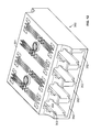
- FIG. 12 illustrates an example optical adapter 350 configured to receive and align two or more optical connectors 300 .
- the optical adapter 350 includes an adapter housing 351 defining two or more ports 352 .
- the optical adapter 350 is a quadruplex adapter that defines four ports 352 at a front side and four ports 352 at a rear side. In other implementations, however, the adapter 350 may include a greater or lesser number of ports 352 on each side.
- Each port 352 defines a notched region 353 sized and shaped to receive the key area 304 , 304 ′ of an optical connector 300 .
- the adapter housing 351 includes a ferrule holder 355 between each set of front and rear ports 352 .
- the ferrule holder 355 includes a splice sleeve that is configured to receive and align a ferrule of an optical connector 300 at each end of the ferrule holder 355 .
- the adapter housing 351 also includes an abutment surface 354 that faces an interior of the adapter housing 351 .
- the abutment surface 354 is sized so that the latching member of the connector 300 may freely pass by the abutment surface 354 when the latching member is lowered. When the latching member is raised, the distal end of the latching member engages the abutment surfaces 354 of the adapter housing 351 (see FIG. 15 ).
- a magnet arrangement 365 is coupled to the adapter housing 351 at the port 352 to interact with the latching member 305 of the connector 300 when the connector 300 is inserted at the adapter housing 351 .
- the magnet arrangement 365 includes at least one permanent magnet 363 and at least one electromagnet 367 ( FIG. 16 ).
- a permanent magnet 363 is a structure that continuously generates a magnetic field.
- an electromagnet 367 is a structure (e.g., a coil of wire) that generates a magnetic field when an electric current is applied and does not generate a magnetic field when an electric current is not applied. The polarization of the magnetic field generating by the electromagnet 367 can be selectively reversed.
- the permanent magnet 363 is sufficiently weak that the magnetic field generated by the permanent magnet is insufficient to attract the magnetizable material of the latching member 305 towards the permanent magnet 363 when the latching member 305 is in the lowered position.
- the permanent magnet 363 is sufficiently strong that the magnetic field generated by the permanent magnet is sufficient to attract the magnetizable material of the latching member 305 when the latching member 305 is in the raised position.
- the electromagnet 367 is sufficiently strong that the magnetic field generated by the activated electromagnet is sufficient to attract the magnetizable material of the latching member 305 when the latching member 305 is in the lowered position.
- the magnet arrangement 365 is disposed within the adapter port 352 so that the permanent magnet 363 is aligned with a portion of the latching member 305 when the connector 300 is fully inserted within the adapter port 352 .
- the permanent magnet 365 is disposed to align with one of the protrusions 310 extending forwardly from the handle 309 of the latching member 305 .
- the magnet arrangement 365 includes two permanent magnets 363 and one electromagnet 367 .
- each permanent magnet 363 aligns with one of the protrusions 310 of the handle 309 .
- the magnet arrangement 365 may include any desired number of permanent and electromagnets.
- FIGS. 24-33 illustrate additional example implementations of a connector body and a latching member.
- FIGS. 24 and 25 illustrate a connector body 601 and a latching member 605 that pivots between a raised position and a lowered position.
- the connector body 601 holds a ferrule 602 .
- a storage device 606 is disposed at a key 604 defined by the body 601 .
- the storage device 606 may be disposed elsewhere on the body 601 .
- the connector body 601 may not have a storage device mounted thereon.
- the latching member 605 is configured to be mounted to the connector body 601 .
- the latching member 605 includes a first pivot pin 607 A and a second pivot pin 607 B that extend away from each other.
- Each pivot pin 607 A, 607 B is sized to be mounted at one of the two spaced-apart support mounts 604 A, 604 B extending from a rear side of the key 604 .
- each pivot pin 607 A, 607 B fits within an opening 611 defined in the respective support mount 604 A, 604 B.
- the pivot pins 607 A, 607 B may be snap-fit, welded, heat-sealed, or otherwise secured within the openings 611 .
- Two spaced-apart arms 608 A, 608 B extends from the pivot pins 607 A, 607 B to a handle 609 .
- the arms 608 A, 608 B are bent or curved.
- the arm 608 A, 608 B may define a planar surface.
- the handle 609 extends transverse to the arm 608 to form a T-shape.
- the handle 609 has a generally rectangular shape.
- the handle 609 has protrusions that extend forwardly of the handle 609 towards the key region 604 .
- the latching member 605 extends rearwardly so that a distal end of the latching member 605 is located closer to the front of the connector body 601 than the distal end of the latching member of the conventional LC-type connector shown in FIG. 23 .
- the arms 608 A, 608 B are sufficiently short so that the distal end of the latching member 605 is fully contained within an adapter port 352 when the connector body 601 is inserted within the adapter port 352 .
- FIGS. 26-29 illustrate another alternative implementation of a connector body 621 having a latching member 625 that pivots between a raised position and a lowered position.
- the connector body 621 holds a ferrule 622 and defines a key region 624 .
- Support mounts 624 A extend rearwardly from the key region 624 and define laterally aligned openings 631 for receiving a pivot pin 627 that extends between the openings 631 .
- the pin 627 is rotationally fixed (e.g., welded, glued, etc.) to the support mounts 624 A.
- the pin 627 is rotatable (e.g., snap-fit) within the openings 631 .
- the latching member 625 includes an arm 628 extending from a handle 629 to a pin-receiving portion 635 .
- the pin-receiving portion 635 is shaped to wrap or fold partially around the pivot pin 627 .
- the pin-receiving portion 635 is configured to rotate about the pivot pin 627 .
- the pin-receiving portion 615 does not fully enclose the pivot pin 627 .
- part of the arm 628 extends parallel with part of the pin-receiving portion 635 .
- the arm 628 is bent or curved between the handle 629 to the pin-receiving portion 635 .
- the handle 629 has a major surface 629 A that extends upwardly form the arm 628 so that an edge 629 B of the handle 629 faces away from the connector body 621 .
- FIGS. 28 and 29 show the connector body 621 on a connector 600 that has been inserted in a port of an example adapter housing 651 .
- the adapter housing 651 is substantially the same as adapter housing 351 of FIGS. 13-15 , except that the orientation of the adapter housing 651 has been flipped and an indicator (e.g., indicator 368 ) is not shown.
- an indicator e.g., indicator 368
- the adapter housing 651 may be equipped with an indicator (e.g., an LED) as shown in FIGS. 13-15 .
- the adapter housing 651 includes an abutment surface 654 that faces an interior of the adapter housing 651 .
- the abutment surface 654 is sized so that the latching member 625 of the connector 600 may freely pass by the abutment surface 654 when the latching member is lowered (see FIG. 28 ).
- the distal end of the latching member 625 engages the abutment surfaces 654 of the adapter housing 651 (see FIG. 29 ).
- a magnet arrangement 665 is coupled to the adapter housing 651 to interact with the latching member 625 of the connector 600 .
- the magnet arrangement 665 is substantially the same as the magnet arrangement 365 of FIGS. 13-15 , except that the magnet arrangement 365 aligns with the edge 629 B of the handle 629 (instead of the major surface 629 A) when the latching member 625 is in the raised position (see FIG. 29 ).
- FIGS. 30-33 illustrate another alternative implementation of a connector body 641 having a latching member 645 that pivots between a raised position and a lowered position.
- the connector body 641 holds a ferrule 642 and defines a key region 644 .
- Support mounts 644 A extend rearwardly from the key region 644 and define laterally aligned openings 671 for receiving a pivot pin 647 that extends between the openings 671 .
- the pin 647 is rotationally fixed (e.g., welded, glued, etc.) to the support mounts 644 A.
- the pin 647 is rotatable (e.g., snap-fit) within the openings 671 .
- the latching member 645 includes an arm 648 extending from a handle 649 to a pin-receiving portion 675 .
- the pin-receiving portion 675 is shaped to wrap or fold partially around the pivot pin 647 .
- the pin-receiving portion 675 is substantially the same as pin-receiving portion 635 of FIG. 26 , except that the pin-receiving portion 675 curves upwardly and away from the connector body 641 and back towards the handle 649 whereas the pin-receiving portion 635 had curved downwardly towards the connector body 621 .
- FIGS. 32 and 33 show the connector body 641 on a connector 640 that has been inserted in a port of an example adapter housing 681 .
- the adapter housing 681 is substantially the same as adapter housings 351 , 651 described above, except that the connector 640 is shown inserted into the left port instead of the right port. Of course, connectors can be received at both ports.
- the adapter housing 651 may be equipped with an indicator (e.g., an LED) as shown in FIGS. 13-15 .
- a magnet arrangement 695 which is substantially the same as magnet arrangement 665 and 365 disclosed herein, is mounted in the adapter 681 and is coupled to a circuit board 690 to actuate the latching member 645 of the connector 640 to releasably lock the connector 640 to the adapter 681 .
- the shape of the latching member 645 allows the arm 648 to pivot within the adapter port while remaining clear of any obstacles. For example, the arm 648 of the latching member 645 stays farther away from the adapter body 681 than the arm 628 of latching member 625 (compare FIG. 33 with FIG. 29 ).
- each adapter 350 of the equipment 370 includes an indicator 368 (e.g., an LED) with which the user's attention may be drawn to a particular adapter on the equipment 370 .
- the equipment 370 may include a display screen on which port identification (e.g., labels) may be listed.
- the communications equipment 370 may be configured to otherwise identify a selected one of the adapters 350 .
- the magnet arrangement 365 and indicator 368 are controlled by a management system 380 .
- the management system 380 determines when the electromagnet 367 is activated, activated with reverse polarization, and deactivated. Accordingly, the management system determines when the connector 300 is secured to the adapter 350 and when the connector 300 is releasable from the adapter 350 .
- the management system 380 also determines when the indicator 368 for each adapter 350 is activated (e.g., lit) and deactivated.
- the management system 380 includes a local processor coupled to the adapter 350 or equipment including the adapter. In other implementations, the management system 380 includes a remote processor 382 coupled to the adapter 350 or equipment including the adapter 350 .
- the management system 380 also includes memory 384 that may store processes or operation implemented by the processor 382 .
- the management system 380 also may include a user interface module 386 with which one or more users communicate with the management system 380 . Additional details regarding example management systems suitable for use in controlling the magnet arrangement 365 as described in more detail below are disclosed in U.S. Publication No. 2011-0262077-A1, filed Feb. 11, 2011, and titled “Managed Fiber Connectivity Systems,” the disclosures of which are hereby incorporated herein by reference.
- the management system 380 determines whether to authorize the insertion. If the insertion is authorized, then the connector 300 is latched in the adapter port 352 . If the insertion is not authorized, then the connector 300 is not latched within the port 352 . In some implementations, authorization is granted if the management system 380 expected a connection to be made at the port 352 and the connector 300 matches predetermined criteria.
- FIG. 17 is a flowchart illustrating an operational flow for an example insertion process 500 by which a user may plug a fiber optic connector 300 into an adapter 350 .
- the process steps may be implemented by one or more users. In certain implementations, the process steps herein described may occur at different times and/or locations.
- the insertion process 500 begins at a start module 502 and proceeds to an access operation 504 .
- the user communicates with the management system 380 .
- the user may communicate with the management system 380 via a direct connection to the user interface module 386 .
- the user may communicate with the management system 380 via a networked computer or handheld processing device (e.g., smart phone, PDA, etc.) that is remotely connected (e.g., via a LAN, a WAN, the Internet, or another network) to the management system 380 .
- a networked computer or handheld processing device e.g., smart phone, PDA, etc.
- the user identifies the adapter port 352 at which the user wants to insert the connector 300 .
- the user may view a port map and identify the port at which the connection should be made.
- the port map is graphically displayed and the user selects an area on the graphic display.
- the user may type or otherwise provide a port identification (e.g., a unique identification number) to the management system 380 .
- the user also may provide the management system 380 with identifying characteristics of the connector 300 to be inserted. For example, the user may provide a unique identification number associated with the connector 300 . In other implementations, the user may provide a cable type, connector type, or other physical feature associated with the connector 300 . In still other implementations, the user may indicate that the connector 300 to be received is a managed connector (i.e., a connector 300 that includes memory storing physical layer information thereabout).
- a managed connector i.e., a connector 300 that includes memory storing physical layer information thereabout.
- the user pushes the connector 300 into an adapter port 352 .
- the user holds the connector 300 in the adapter port 350 (see hold operation 510 ) until the management system 380 indicates that an action has been taken.
- the action includes latching the connector 300 into the adapter port 352 if the management system 380 determines that insertion is authorized as disclosed in more detail below.
- the action includes issuing an alarm or error if the management system 380 determines that insertion is not authorized as disclosed in more detail below.
- the insertion operation 500 performs any appropriate completion procedures and ends at a stop module 512 .
- FIG. 18 is a flowchart illustrating an operational flow for an authorization process 520 by which the management system 380 determines whether or not a connector insertion is appropriate.
- the process steps may be implemented by one or more processors associated with the management system 380 . In certain implementations, the process steps are implemented locally at the adapter 350 or adapter equipment. In other implementations, the process steps are implemented at a location remote from the adapters 350 .
- the insertion authorization process 520 begins at a start module 522 and proceeds to a determine operation 524 .
- the determine operation 524 determines that a connector 300 has been or is being inserted into one of the adapters 350 associated with the management system 380 .
- the management system 380 may determine that a switch has been opened or closed, thereby indicating that a connector 300 has been inserted into the adapter 350 .
- the determine operation 524 may be implemented during or after insertion of the connector 300 into the adapter 350 .
- the connector 300 pushes against electrical contacts 362 when inserted, thereby completing a circuit between the contacts 362 and a printed circuit board 360 associated with the adapter 350 .
- other types of presence sensors e.g., pressure sensors, light sensors, etc. may be utilized.
- An obtain operation 526 reads or attempts to read data stored in the memory of the connector 300 . If the connector 300 being inserted includes memory 306 , then the obtain operation 526 retrieves some or all of the data stored in the memory and sends the data to the management system 380 for processing. In some implementations, the data is sent to a local processor at the adapter equipment. In other implementations, the data is sent to a remote processor. In some implementations, the obtain operation 526 retrieves a unique identifier associated with the connector 300 . In other implementations, the obtain operation 526 retrieves physical layer information (e.g., cable type, cable length, connector type, insertion count, security clearance, etc.) pertaining to the connector 300 or cable terminated thereat.
- physical layer information e.g., cable type, cable length, connector type, insertion count, security clearance, etc.
- a determination module 528 implemented by the management system 380 determines whether the insertion of the connector 300 at the adapter port 352 should be allowed. For example, in some implementations, the management system 380 determines whether a unique identifier read from the connector memory 306 matches an expected unique identifier provided by a user prior to the insertion. In other implementations, the management system 380 determines whether other types of data read from the memory 306 matches the expected data (e.g., whether the connector 300 is the expected connector type, whether the connector 300 terminates a cable of the expected cable type, whether the connector 300 is associated with the expected security clearance, etc.).
- the management system 380 determines that authorization should be provided, then the management system 380 temporarily activates (e.g., pulses) the magnet arrangement 365 at an actuate operation 530 .
- the management system 380 may activate the electromagnet 367 to create a magnetic field that is sufficiently strong to pull the latch 305 towards the permanent magnet 363 .
- the management system 380 also activates an indicator 368 associated with the adapter port 352 or adapter equipment at an indicate operation 532 .
- the management system 380 may light an LED or other light source associated with the port 352 . Activating the indicator tells the user that the connector 300 has been latched.
- the management system 380 determines that authorization should not be provided, then the management system 380 implements an error operation 534 at which the user is informed that authorization is not granted.
- the error operation 534 does not light an indicator light (e.g., LED) associated with the port.
- the error operation 534 activates the indicator light with a warning color (e.g., red) or pattern (e.g., flashing).
- the error operation 534 sounds an auditory alarm.
- the error operation 534 sends an alert message to the user or to an administrator of the management network or security personnel.
- the management system 380 implements an eject operation 536 at which the management system 380 instructs the adapter 350 to physically push or otherwise attempt to force the connector 300 out of the port 352 .
- the ejector 356 applies a pressure to the connector 300 to push the connector 300 sufficiently out of the port 352 to prevent transmission of a signal from or to the connector 300 .
- the ejector 356 pushes the connector 300 completely outside of the adapter port 352 .
- FIG. 21 illustrates an adapter 350 including an example ejector 356 disposed within the adapter port 352 .
- the example ejector 356 includes a spring 358 that biases the ejector 356 towards the open end of the port 352 .
- the ejector 356 is shaped and configured to engage part of a connector 300 that has been inserted into the respective adapter port 352 at least when the ejector 356 is actuated.
- the ejector 356 is held (e.g., physically, magnetically, etc.) in a retracted position against the bias of the spring 358 until actuated by the management system 380 .
- the management system 380 releases the ejector 356 to be freely biased by the spring 358 .
- the insertion authorization operation 520 performs any appropriate completion procedures and ends at a stop module 538 .
- a connector 300 may be removed from an adapter port 352 when the management system 380 determines that such a removal is authorized.
- a user provides a request to the management system 380 that a particular connector 300 be unlatched to facilitate removal of the connector 300 from the port 352 .
- the user signals the management system to unlatch the connector 300 .
- the management system 380 unlatches the requested connector 300 .
- FIG. 19 is a flowchart illustrating an operational flow for an example removal process 550 by which a user may pull or otherwise remove a fiber optic connector 300 from an adapter port 352 .
- the process steps may be implemented by one or more users. In certain implementations, the process steps herein described may occur at different times and/or locations.
- the removal process 550 begins at a start module 552 and proceeds to an access operation 554 .
- the user communicates with the management system 380 .
- the user may communicate with the management system 380 via a direct connection to the user interface module 386 .
- the user may communicate with the management system 380 via a networked computer or handheld processing device (e.g., smart phone, PDA, etc.) that is remotely connected (e.g., via a LAN, a WAN, the Internet, or another network) to the management system 380 .
- a networked computer or handheld processing device e.g., smart phone, PDA, etc.
- the user identifies the adapter port 352 from which the user wants to remove the connector 300 and/or the user identifies the connector 300 that the user wants to remove.
- the user may view a port map and identify the port at which the disconnection should be made.
- the port map is graphically displayed and the user selects an area on the graphic display.
- the user may type or otherwise provide a port identification (e.g., a unique identification number) and/or a connector identification to the management system 380 .
- the user pushes a button or otherwise actuates an input member to provide an indication to the management system 380 that the user is ready to remove a connector.
- the user pushes a button 375 ( FIG. 16 ) that is associated with multiple adapters 350 on a piece of adapter equipment.
- the user pushes a button ( 359 ) associated with a particular adapter port 352 .
- the user directly depresses the button with a finger of the user.
- the user indirectly actuates the button as will be described in more detail herein.
- the user indicates readiness using a biometric device (e.g., a fingerprint scanner).
- the biometric device analyzes biometric data (e.g., a scanned fingerprint) to identify the user.
- the management system 380 may check whether the identified user is authorized to remove the connector 300 or otherwise modify the connections of the system.
- the user pushes the connector 300 forwardly into the adapter port 352 (see push operation 560 ) until the management system 380 indicates (e.g., via indicator 368 ) that an action has been taken.
- the action includes unlatching the connector 300 .
- the action may include ejecting the connector 300 from the port 352 .
- the action may include issuing an alarm or error.
- the user implements the push operation 560 before the indicate operation 558 .
- FIG. 22 illustrates a connector 300 disposed within a port 352 of an adapter 350 having an internal input member 359 .
- the internal input member 359 is a micro-switch that is electrically connected to the circuit board 360 (e.g., via a circuit board 357 or other electrical connecting structure).
- pushing the connector 300 into the port 352 actuates the internal input member 359 , which triggers the management system 380 to act (e.g., release the latch 305 of the connector 300 ).
- the user may pull the connector 300 out of the port 352 at a remove operation 362 .
- the removal may be assisted by an ejector 356 .
- the removal operation 550 performs any appropriate completion procedures and ends at a stop module 564 .
- FIG. 20 is a flowchart illustrating an operational flow for an authorization process 570 by which the management system 380 determines whether or not removal of a connector from an adapter port is appropriate.
- the process steps may be implemented by one or more processors associated with the management system 380 . In certain implementations, the process steps are implemented locally at the adapter 350 or adapter equipment. In other implementations, the process steps are implemented at a location remote from the adapters 350 .
- the removal authorization process 570 begins at a start module 572 and proceeds to a receive operation 574 .
- the receive operation 574 obtains a selection of a desired connector 300 to be removed (i.e., or an adapter port 352 from which a connector 300 is desired to be removed). In some implementations, the receive operation 574 obtains a connector selection or port selection from a user via the user interface 386 of the management system 380 ( FIG. 16 ). In certain implementations, the selection is obtained using a graphic interface. In certain implementations, the selection is obtained via a port identification number (or alphanumeric code) or connector identification number (or alphanumeric code). In certain implementations, the receiver operation 574 obtains multiple selections from the user.
- a determine operation 576 receives an indication from a user that the user is ready to disconnect the selected connector 300 (i.e., to disconnect the connector 300 plugged into the selected port 352 ).
- the determine operation 576 may receive and process a signal from a push button 359 , 375 or other input member actuated manually by the user.
- the input member 359 , 375 is located at the adapter 350 or adapter equipment.
- one input member 375 ( FIG. 16 ) is associated with all ports 352 defined by the adapter equipment.
- each adapter port 352 is associated with its own input member 359 ( FIG. 22 ).
- a first determination module 578 determines whether the readiness indication received in the determine operation 576 identifies a particular port 352 from which a connector 300 is to be removed (i.e., or a particular connector 300 to be removed). If the readiness indication does not identify a particular port 352 or connector 300 , then the management system 380 implements a flip operation 580 to actuate the electromagnet 367 associated with the port 352 or connector 300 identified in the receive operation 572 . However, the management system 380 reverses (i.e., flips) the polarity of the magnetic field generated by the electromagnet 367 , thereby repelling the connector latch 305 away from the permanent magnet 363 .
- the management system 380 actuates an indicator 368 to denote the connector 300 being unlatched from the port 352 .
- the indicator 368 visually denotes unlatching (e.g., lights an LED, flashes an LED, changes the color of an LED).
- the indicator 368 audibly denotes unlatching.
- the management system 380 may actuate an ejection member 356 during an eject operation 584 to aid in removing the unlatched connector 300 from the port 352 .
- the management system 380 may release an ejector spring 358 to bias the connector 300 out of the port 352 .
- the management system 380 implements a compare operation 586 that determines whether the user has identified the connector 300 preselected for removal. If the readiness indication identifies the preselected connector 300 or port 352 (see the second determination module 588 ), then the management system 380 implements the flip operation 580 and proceeds as described above.
- the management system 380 implements an error operation 590 .
- the second determination module 588 determines that no connector 300 or port 352 has been preselected, then the management system 380 will proceed to the error operation 590 .
- the error operation 590 provides an indication to the user that the user is attempting an unauthorized removal of a connector.
- the error operation 590 may generate or trigger a visual alarm (e.g., a flashing LED), an audible alarm, or some other type of alert.
- the error operation 590 will identify (e.g., flash an LED located at) the connector 300 preselected for removal.
- the removal authorization operation 570 performs any appropriate completion procedures and ends at a stop module 592 .
- the management system 380 includes tamper detection sensors (e.g., Hall sensors) disposed at the adapter 350 or adapter equipment to detect when a magnetic field is being applied within the port. The management system 380 may determine whether or not a detected magnetic field is occurring only when the magnet arrangement 365 is actuated. If a magnetic field is detected, but the magnet arrangement 365 is not actuated, then the management system 380 may generate an alert. Such an alert will inhibit a user from forcing an unauthorized connection or removal using an external magnet.
- tamper detection sensors e.g., Hall sensors
- latching techniques and management system can be applied to other types of optical connectors (e.g., MPO connectors, LX.5 connectors, etc.), to electrical connectors (e.g., RJ45 connectors, RJpoint5 connectors, USB connectors, etc.) and sockets, or to hybrid or mixed media connectors and adapters.
- optical connectors e.g., MPO connectors, LX.5 connectors, etc.
- electrical connectors e.g., RJ45 connectors, RJpoint5 connectors, USB connectors, etc.
- sockets e.g., RJ45 connectors, RJpoint5 connectors, USB connectors, etc.
Abstract
Description
Claims (19)
Priority Applications (1)
| Application Number | Priority Date | Filing Date | Title |
|---|---|---|---|
| US14/745,571 US9500817B2 (en) | 2012-05-18 | 2015-06-22 | Connectors and adapters with auto-latching features |
Applications Claiming Priority (4)
| Application Number | Priority Date | Filing Date | Title |
|---|---|---|---|
| US201261648976P | 2012-05-18 | 2012-05-18 | |
| US201261670460P | 2012-07-11 | 2012-07-11 | |
| US13/896,797 US9063298B2 (en) | 2012-05-18 | 2013-05-17 | Connectors and adapters with auto-latching features |
| US14/745,571 US9500817B2 (en) | 2012-05-18 | 2015-06-22 | Connectors and adapters with auto-latching features |
Related Parent Applications (1)
| Application Number | Title | Priority Date | Filing Date |
|---|---|---|---|
| US13/896,797 Division US9063298B2 (en) | 2012-05-18 | 2013-05-17 | Connectors and adapters with auto-latching features |
Publications (2)
| Publication Number | Publication Date |
|---|---|
| US20150293311A1 US20150293311A1 (en) | 2015-10-15 |
| US9500817B2 true US9500817B2 (en) | 2016-11-22 |
Family
ID=49584334
Family Applications (2)
| Application Number | Title | Priority Date | Filing Date |
|---|---|---|---|
| US13/896,797 Active 2033-06-04 US9063298B2 (en) | 2012-05-18 | 2013-05-17 | Connectors and adapters with auto-latching features |
| US14/745,571 Active US9500817B2 (en) | 2012-05-18 | 2015-06-22 | Connectors and adapters with auto-latching features |
Family Applications Before (1)
| Application Number | Title | Priority Date | Filing Date |
|---|---|---|---|
| US13/896,797 Active 2033-06-04 US9063298B2 (en) | 2012-05-18 | 2013-05-17 | Connectors and adapters with auto-latching features |
Country Status (10)
| Country | Link |
|---|---|
| US (2) | US9063298B2 (en) |
| EP (1) | EP2850477A4 (en) |
| CN (1) | CN104471454B (en) |
| AU (1) | AU2013262558A1 (en) |
| BR (1) | BR112014028660A2 (en) |
| CA (1) | CA2873866A1 (en) |
| CL (1) | CL2014003127A1 (en) |
| MX (1) | MX2014014008A (en) |
| WO (1) | WO2013173726A1 (en) |
| ZA (1) | ZA201409208B (en) |
Cited By (5)
| Publication number | Priority date | Publication date | Assignee | Title |
|---|---|---|---|---|
| US20170207574A1 (en) * | 2014-05-05 | 2017-07-20 | 3M Innovative Properties Company | Lan connector with unlocking preventing mechanism |
| US20170272841A1 (en) * | 2014-12-01 | 2017-09-21 | 3M Innovative Properties Company | Upgradeable distribution framework, cable connector, and cabling management system |
| US10483688B2 (en) * | 2017-06-14 | 2019-11-19 | Microsoft Technology Licensing, Llc | Magnetically activated latch mechanism |
| US11169332B2 (en) * | 2017-08-18 | 2021-11-09 | Commscope Technologies Llc | Fiber optic connector with unitary housing and fiber optic connector assembly |
| US11215769B2 (en) | 2019-03-07 | 2022-01-04 | Mellanox Technologies, Ltd. | MPO locking |
Families Citing this family (33)
| Publication number | Priority date | Publication date | Assignee | Title |
|---|---|---|---|---|
| JP5778696B2 (en) * | 2010-02-12 | 2015-09-16 | エーディーシー テレコミュニケーションズ,インコーポレイティド | Managed fiber connection system |
| CA2873866A1 (en) | 2012-05-18 | 2013-11-21 | Adc Telecommunications, Inc. | Connectors and adapters with auto-latching features |
| US9075205B2 (en) | 2012-07-11 | 2015-07-07 | Tyco Electronics Corporation | Connectors and adapters with auto-latching features |
| US9620886B1 (en) * | 2013-10-15 | 2017-04-11 | Google Inc. | Electrical connector with recessed contact and socket for receiving electrical connector |
| USD947053S1 (en) | 2014-08-11 | 2022-03-29 | Apple Inc. | Wearable device |
| US10495826B2 (en) * | 2014-09-26 | 2019-12-03 | Hewlett Packard Enterprise Development Lp | Receptacle for connecting a multi-lane or one-lane cable |
| WO2016053386A1 (en) * | 2014-10-02 | 2016-04-07 | Adc Telecommunications, Inc. | Systems and methods for connectors with insertion counters |
| FR3028100B1 (en) * | 2014-11-05 | 2016-12-30 | Schneider Electric Ind Sas | SYSTEM COMPRISING A SOCKET AND A HOT-OUTLET MODULE |
| US10345526B2 (en) * | 2014-12-14 | 2019-07-09 | Telescent Inc. | High reliability robotic cross-connect systems |
| EP3958408A1 (en) * | 2015-07-01 | 2022-02-23 | Go!Foton Holdings, Inc. | Connector engagement sensing mechanism |
| WO2017132549A1 (en) * | 2016-01-28 | 2017-08-03 | Commscope Technologies Llc | Optical power detector and reader |
| EP3411963A1 (en) | 2016-02-04 | 2018-12-12 | CommScope Connectivity Belgium BVBA | Apparatus for monitoring fiber signal traffic at a fiber connector |
| CN105467529B (en) * | 2016-02-16 | 2017-04-12 | 常州太平通讯科技有限公司 | Intelligent optical fiber connector device |
| JP1563320S (en) * | 2016-03-08 | 2016-11-14 | ||
| JP1563240S (en) * | 2016-03-08 | 2016-11-14 | ||
| JP1563321S (en) * | 2016-03-08 | 2016-11-14 | ||
| JP1563322S (en) * | 2016-03-08 | 2016-11-14 | ||
| US10120140B2 (en) * | 2017-01-25 | 2018-11-06 | Fluke Corporation | Connector and duplex connector assembly |
| US10871619B2 (en) * | 2017-01-30 | 2020-12-22 | Senko Advanced Components, Inc. | Cassette assembly for a plural of fiber optic receptacles |
| JP6546621B2 (en) * | 2017-06-20 | 2019-07-17 | 矢崎総業株式会社 | Vehicle sun visor |
| DE102017114260A1 (en) * | 2017-06-27 | 2018-12-27 | Aesculap Ag | Medical hand instrument with cleaning-optimized spring element |
| WO2019018677A1 (en) * | 2017-07-19 | 2019-01-24 | Fiber Mountain, Inc. | Fiber connector assembly |
| US11226453B2 (en) * | 2017-08-09 | 2022-01-18 | Commscope Technologies Llc | Board mounted active component assembly |
| JP7084263B2 (en) * | 2018-09-14 | 2022-06-14 | 三和電気工業株式会社 | Optical connector plug connection detection mechanism |
| TWI695199B (en) * | 2018-09-28 | 2020-06-01 | 光興國際股份有限公司 | Optical to electrical adapter |
| WO2020146046A1 (en) * | 2019-01-07 | 2020-07-16 | Leviton Manufacturing Co., Inc. | An electrical device with built-in sensors and/or communications |
| CN110401063A (en) * | 2019-08-02 | 2019-11-01 | 昆山思雷电子科技有限公司 | A kind of multifunctional panel connector |
| US11226452B2 (en) * | 2020-05-11 | 2022-01-18 | Google Llc | Dual polarity optical fiber adaptor with protruding tab and patch panel |
| WO2022159577A1 (en) * | 2021-01-22 | 2022-07-28 | Commscope Technologies Llc | Automatic shutter assembly for multi-fiber connection systems |
| CN113253393B (en) * | 2021-04-28 | 2022-11-22 | 武汉光迅科技股份有限公司 | Magnetic attraction type optical fiber assembly with unlocking function and using method thereof |
| CN113189714B (en) * | 2021-04-28 | 2022-05-27 | 武汉光迅科技股份有限公司 | Magnetic type optical fiber assembly and use method thereof |
| US11644628B1 (en) * | 2022-01-28 | 2023-05-09 | Ciena Corporation | Micro-optical connector holder with integrated mating system |
| CN114879317B (en) * | 2022-06-15 | 2023-08-04 | 北京瑞祺皓迪技术股份有限公司 | Magnetic type optical fiber connecting device and optical fiber wiring method |
Citations (31)
| Publication number | Priority date | Publication date | Assignee | Title |
|---|---|---|---|---|
| US2735991A (en) | 1956-02-21 | Magnet controlled connectors | ||
| US3926493A (en) | 1973-12-04 | 1975-12-16 | Nippon Kogaku Kk | Connecting device |
| US5297968A (en) | 1993-01-12 | 1994-03-29 | The Whitaker Corporation | Pluggable connector systems for flexible etched circuits |
| US5420951A (en) * | 1992-11-26 | 1995-05-30 | Diamond Sa | Locking fiber optic connector receptacle |
| DE10056410A1 (en) | 2000-11-14 | 2002-05-23 | Daimler Chrysler Ag | Electrical pluggable connection, uses magnetic armature to latch inter-plugged parts in locking position |
| US6511231B2 (en) | 2000-12-27 | 2003-01-28 | Fitel Usa Corp. | Optical connector receptacle having switching capability |
| US20040010250A1 (en) | 2002-07-11 | 2004-01-15 | Ronald R. Manna | Medical handpiece with automatic power switching means |
| US20040151464A1 (en) | 2003-01-30 | 2004-08-05 | Marrs Samuel M. | Tuning tool for tunable fiber optic connector |
| US6821024B2 (en) * | 2003-04-08 | 2004-11-23 | Itt Manufacturing Enterprises, Inc. | Connector secondary latch |
| JP2005115324A (en) | 2003-05-30 | 2005-04-28 | Sumitomo Electric Ind Ltd | Optical module |
| US6966788B1 (en) | 2005-03-15 | 2005-11-22 | Ruhl Jr Harold John | Anti-decoupling mechanism for solid or tubular circular cross section assemblies having a rotating coupling nut or nuts |
| US20060093273A1 (en) | 2004-11-03 | 2006-05-04 | Fenwick David M | Optical connections and methods of forming optical connections |
| US7128471B2 (en) | 2004-05-06 | 2006-10-31 | Avago Technologies Fiber Ip (Singapore) Pte. Ltd. | Single-use fiber optic cable |
| US7226217B1 (en) | 2005-11-18 | 2007-06-05 | Stratos International, Inc. | Transceiver/fiber optic connector adaptor with patch cord ID reading capability |
| US7229220B2 (en) | 2003-12-06 | 2007-06-12 | Hon Hai Precision Ind. Co., Ltd. | Optical fiber connector |
| WO2007103689A2 (en) | 2006-03-01 | 2007-09-13 | Panduit Corp. | Plug locking assembly |
| US20080116678A1 (en) | 2005-02-08 | 2008-05-22 | Polycontact Ag | Insertion Part for a Seat Belt Lock, a Lock Provided with Said Insertion Part |
| WO2009006400A1 (en) | 2007-07-03 | 2009-01-08 | Panduit Corp. | Plug locking assembly and system |
| US7494363B1 (en) | 2008-06-27 | 2009-02-24 | Hon Hai Precision Ind. Co., Ltd. | Plug connector having a latching mechanism |
| US7553179B2 (en) | 2007-08-07 | 2009-06-30 | Itt Manufacturing Enterprises, Inc. | Connector latch retainer |
| US20090269943A1 (en) | 2007-12-24 | 2009-10-29 | Craig Palli | Magnetic and Locking Cable Connectors |
| US20100029117A1 (en) | 2008-08-01 | 2010-02-04 | Verizon Corporate Services Group Inc. | Computer-controlled connector-panel system |
| US20100232756A1 (en) * | 2009-03-16 | 2010-09-16 | Panduit Corp. | Block-Out Device For Fiber Optic Adapter |
| US20100233889A1 (en) | 2009-03-11 | 2010-09-16 | Kiani Massi Joe E | Magnetic connector |
| US20110092100A1 (en) * | 2009-10-16 | 2011-04-21 | Adc Telecommunications, Inc. | Managed connectivity in electrical systems and methods thereof |
| US20110222819A1 (en) | 2010-02-12 | 2011-09-15 | John Anderson | Managed fiber connectivity systems |
| US20110317976A1 (en) | 2008-12-01 | 2011-12-29 | Reichle & De-Massari Ag | Security system for optical plug-in connector |
| US20120148195A1 (en) | 2010-12-09 | 2012-06-14 | Microsoft Corporation | Power and data connector |
| US20120155803A1 (en) | 2010-12-07 | 2012-06-21 | Benjamin Seldon D | Ferrule assemblies, connector assemblies, and optical couplings having coded magnetic arrays |
| US20140016902A1 (en) | 2012-07-11 | 2014-01-16 | Adc Telecommunications, Inc. | Connectors and adapters with auto-latching features |
| US9063298B2 (en) | 2012-05-18 | 2015-06-23 | Tyco Electronics Corporation | Connectors and adapters with auto-latching features |
Family Cites Families (1)
| Publication number | Priority date | Publication date | Assignee | Title |
|---|---|---|---|---|
| US7073953B2 (en) * | 2001-08-31 | 2006-07-11 | Amphenol Corporation | Modular fiber optic connection system |
-
2013
- 2013-05-17 CA CA2873866A patent/CA2873866A1/en not_active Abandoned
- 2013-05-17 WO PCT/US2013/041612 patent/WO2013173726A1/en active Application Filing
- 2013-05-17 AU AU2013262558A patent/AU2013262558A1/en not_active Abandoned
- 2013-05-17 BR BR112014028660A patent/BR112014028660A2/en not_active IP Right Cessation
- 2013-05-17 US US13/896,797 patent/US9063298B2/en active Active
- 2013-05-17 EP EP13790549.3A patent/EP2850477A4/en not_active Withdrawn
- 2013-05-17 MX MX2014014008A patent/MX2014014008A/en not_active Application Discontinuation
- 2013-05-17 CN CN201380037297.2A patent/CN104471454B/en active Active
-
2014
- 2014-11-18 CL CL2014003127A patent/CL2014003127A1/en unknown
- 2014-12-15 ZA ZA2014/09208A patent/ZA201409208B/en unknown
-
2015
- 2015-06-22 US US14/745,571 patent/US9500817B2/en active Active
Patent Citations (34)
| Publication number | Priority date | Publication date | Assignee | Title |
|---|---|---|---|---|
| US2735991A (en) | 1956-02-21 | Magnet controlled connectors | ||
| US3926493A (en) | 1973-12-04 | 1975-12-16 | Nippon Kogaku Kk | Connecting device |
| US5420951A (en) * | 1992-11-26 | 1995-05-30 | Diamond Sa | Locking fiber optic connector receptacle |
| US5297968A (en) | 1993-01-12 | 1994-03-29 | The Whitaker Corporation | Pluggable connector systems for flexible etched circuits |
| DE10056410A1 (en) | 2000-11-14 | 2002-05-23 | Daimler Chrysler Ag | Electrical pluggable connection, uses magnetic armature to latch inter-plugged parts in locking position |
| US6511231B2 (en) | 2000-12-27 | 2003-01-28 | Fitel Usa Corp. | Optical connector receptacle having switching capability |
| US20040010250A1 (en) | 2002-07-11 | 2004-01-15 | Ronald R. Manna | Medical handpiece with automatic power switching means |
| US20040151464A1 (en) | 2003-01-30 | 2004-08-05 | Marrs Samuel M. | Tuning tool for tunable fiber optic connector |
| US6821024B2 (en) * | 2003-04-08 | 2004-11-23 | Itt Manufacturing Enterprises, Inc. | Connector secondary latch |
| JP2005115324A (en) | 2003-05-30 | 2005-04-28 | Sumitomo Electric Ind Ltd | Optical module |
| US7229220B2 (en) | 2003-12-06 | 2007-06-12 | Hon Hai Precision Ind. Co., Ltd. | Optical fiber connector |
| US7128471B2 (en) | 2004-05-06 | 2006-10-31 | Avago Technologies Fiber Ip (Singapore) Pte. Ltd. | Single-use fiber optic cable |
| US20060093273A1 (en) | 2004-11-03 | 2006-05-04 | Fenwick David M | Optical connections and methods of forming optical connections |
| US20080116678A1 (en) | 2005-02-08 | 2008-05-22 | Polycontact Ag | Insertion Part for a Seat Belt Lock, a Lock Provided with Said Insertion Part |
| US6966788B1 (en) | 2005-03-15 | 2005-11-22 | Ruhl Jr Harold John | Anti-decoupling mechanism for solid or tubular circular cross section assemblies having a rotating coupling nut or nuts |
| US7226217B1 (en) | 2005-11-18 | 2007-06-05 | Stratos International, Inc. | Transceiver/fiber optic connector adaptor with patch cord ID reading capability |
| WO2007103689A2 (en) | 2006-03-01 | 2007-09-13 | Panduit Corp. | Plug locking assembly |
| WO2009006400A1 (en) | 2007-07-03 | 2009-01-08 | Panduit Corp. | Plug locking assembly and system |
| US7553179B2 (en) | 2007-08-07 | 2009-06-30 | Itt Manufacturing Enterprises, Inc. | Connector latch retainer |
| US20090269943A1 (en) | 2007-12-24 | 2009-10-29 | Craig Palli | Magnetic and Locking Cable Connectors |
| US7494363B1 (en) | 2008-06-27 | 2009-02-24 | Hon Hai Precision Ind. Co., Ltd. | Plug connector having a latching mechanism |
| US20100029117A1 (en) | 2008-08-01 | 2010-02-04 | Verizon Corporate Services Group Inc. | Computer-controlled connector-panel system |
| US20110317976A1 (en) | 2008-12-01 | 2011-12-29 | Reichle & De-Massari Ag | Security system for optical plug-in connector |
| US20100233889A1 (en) | 2009-03-11 | 2010-09-16 | Kiani Massi Joe E | Magnetic connector |
| US20100232756A1 (en) * | 2009-03-16 | 2010-09-16 | Panduit Corp. | Block-Out Device For Fiber Optic Adapter |
| US20110092100A1 (en) * | 2009-10-16 | 2011-04-21 | Adc Telecommunications, Inc. | Managed connectivity in electrical systems and methods thereof |
| US20110222819A1 (en) | 2010-02-12 | 2011-09-15 | John Anderson | Managed fiber connectivity systems |
| US20110235979A1 (en) | 2010-02-12 | 2011-09-29 | John Anderson | Managed fiber connectivity systems |
| US20110255829A1 (en) | 2010-02-12 | 2011-10-20 | John Anderson | Managed fiber connectivity systems |
| US20110262077A1 (en) | 2010-02-12 | 2011-10-27 | John Anderson | Managed fiber connectivity systems |
| US20120155803A1 (en) | 2010-12-07 | 2012-06-21 | Benjamin Seldon D | Ferrule assemblies, connector assemblies, and optical couplings having coded magnetic arrays |
| US20120148195A1 (en) | 2010-12-09 | 2012-06-14 | Microsoft Corporation | Power and data connector |
| US9063298B2 (en) | 2012-05-18 | 2015-06-23 | Tyco Electronics Corporation | Connectors and adapters with auto-latching features |
| US20140016902A1 (en) | 2012-07-11 | 2014-01-16 | Adc Telecommunications, Inc. | Connectors and adapters with auto-latching features |
Non-Patent Citations (4)
| Title |
|---|
| European Search Report for Application No. 13790549.3 mailed Jan. 25, 2016. |
| International Search Report and Written Opinion for PCT/US2013/041612 mailed Aug. 27, 2013. |
| International Search Report and Written Opinion for PCT/US2013/049928 mailed Oct. 22, 2013. |
| New Zealand First Examination Report dated Sep. 15, 2015, 3 pages. |
Cited By (8)
| Publication number | Priority date | Publication date | Assignee | Title |
|---|---|---|---|---|
| US20170207574A1 (en) * | 2014-05-05 | 2017-07-20 | 3M Innovative Properties Company | Lan connector with unlocking preventing mechanism |
| US10003158B2 (en) * | 2014-05-05 | 2018-06-19 | 3M Innovative Properties Company | LAN connector with unlocking preventing mechanism |
| US20170272841A1 (en) * | 2014-12-01 | 2017-09-21 | 3M Innovative Properties Company | Upgradeable distribution framework, cable connector, and cabling management system |
| US10136195B2 (en) * | 2014-12-01 | 2018-11-20 | Alliance Fiber Optic Products, Inc. | Upgradeable distribution framework, cable connector, and cabling management system |
| US10483688B2 (en) * | 2017-06-14 | 2019-11-19 | Microsoft Technology Licensing, Llc | Magnetically activated latch mechanism |
| US11169332B2 (en) * | 2017-08-18 | 2021-11-09 | Commscope Technologies Llc | Fiber optic connector with unitary housing and fiber optic connector assembly |
| US11754789B2 (en) | 2017-08-18 | 2023-09-12 | Commscope Technologies Llc | Fiber optic connector with unitary housing and fiber optic connector assembly |
| US11215769B2 (en) | 2019-03-07 | 2022-01-04 | Mellanox Technologies, Ltd. | MPO locking |
Also Published As
| Publication number | Publication date |
|---|---|
| ZA201409208B (en) | 2016-08-31 |
| CN104471454B (en) | 2017-07-28 |
| AU2013262558A1 (en) | 2014-12-11 |
| US9063298B2 (en) | 2015-06-23 |
| WO2013173726A1 (en) | 2013-11-21 |
| EP2850477A1 (en) | 2015-03-25 |
| CL2014003127A1 (en) | 2015-08-21 |
| CA2873866A1 (en) | 2013-11-21 |
| EP2850477A4 (en) | 2016-02-24 |
| MX2014014008A (en) | 2015-06-10 |
| US20130323940A1 (en) | 2013-12-05 |
| BR112014028660A2 (en) | 2017-06-27 |
| CN104471454A (en) | 2015-03-25 |
| US20150293311A1 (en) | 2015-10-15 |
Similar Documents
| Publication | Publication Date | Title |
|---|---|---|
| US9500817B2 (en) | Connectors and adapters with auto-latching features | |
| US10761274B2 (en) | Connectors and adapters with auto-latching features | |
| EP1271205B1 (en) | Optical connector plug | |
| US6554484B2 (en) | Optical connector receptacle having switching capability | |
| US7674046B2 (en) | Fibre optic connector keying system | |
| EP1237024B1 (en) | Optical connector receptacle having electrical switching capability | |
| US7540667B2 (en) | Positional differentiating connector assembly | |
| US7258493B2 (en) | Keyed fibre optic connector | |
| US9453971B2 (en) | Managed fiber connectivity systems | |
| US7706657B1 (en) | Fiber optic parking dust cover | |
| JP2008535029A (en) | Plug-in connector device | |
| US20170256970A1 (en) | Pairable usb cable locking charger | |
| CA2441872A1 (en) | Keyed fibre optic connector | |
| CA2540114C (en) | Keyed fibre optic connector | |
| JP2004226564A (en) | Optical connector and housing with data recording part | |
| CN110459918A (en) | A kind of cabinet adapter |
Legal Events
| Date | Code | Title | Description |
|---|---|---|---|
| AS | Assignment |
Owner name: ADC TELECOMMUNICATIONS, INC., PENNSYLVANIA Free format text: ASSIGNMENT OF ASSIGNORS INTEREST;ASSIGNOR:TYCO ELECTRONICS CORPORATION;REEL/FRAME:036907/0571 Effective date: 20150824 |
|
| AS | Assignment |
Owner name: TYCO ELECTRONICS SERVICES GMBH, SWITZERLAND Free format text: ASSIGNMENT OF ASSIGNORS INTEREST;ASSIGNORS:ADC TELECOMMUNICATIONS, INC.;TE CONNECTIVITY SOLUTIONS GMBH;REEL/FRAME:036908/0443 Effective date: 20150825 |
|
| AS | Assignment |
Owner name: COMMSCOPE EMEA LIMITED, IRELAND Free format text: ASSIGNMENT OF ASSIGNORS INTEREST;ASSIGNOR:TYCO ELECTRONICS SERVICES GMBH;REEL/FRAME:036956/0001 Effective date: 20150828 |
|
| AS | Assignment |
Owner name: COMMSCOPE TECHNOLOGIES LLC, NORTH CAROLINA Free format text: ASSIGNMENT OF ASSIGNORS INTEREST;ASSIGNOR:COMMSCOPE EMEA LIMITED;REEL/FRAME:037012/0001 Effective date: 20150828 |
|
| AS | Assignment |
Owner name: JPMORGAN CHASE BANK, N.A., AS COLLATERAL AGENT, ILLINOIS Free format text: PATENT SECURITY AGREEMENT (TERM);ASSIGNOR:COMMSCOPE TECHNOLOGIES LLC;REEL/FRAME:037513/0709 Effective date: 20151220 Owner name: JPMORGAN CHASE BANK, N.A., AS COLLATERAL AGENT, ILLINOIS Free format text: PATENT SECURITY AGREEMENT (ABL);ASSIGNOR:COMMSCOPE TECHNOLOGIES LLC;REEL/FRAME:037514/0196 Effective date: 20151220 Owner name: JPMORGAN CHASE BANK, N.A., AS COLLATERAL AGENT, IL Free format text: PATENT SECURITY AGREEMENT (TERM);ASSIGNOR:COMMSCOPE TECHNOLOGIES LLC;REEL/FRAME:037513/0709 Effective date: 20151220 Owner name: JPMORGAN CHASE BANK, N.A., AS COLLATERAL AGENT, IL Free format text: PATENT SECURITY AGREEMENT (ABL);ASSIGNOR:COMMSCOPE TECHNOLOGIES LLC;REEL/FRAME:037514/0196 Effective date: 20151220 |
|
| STCF | Information on status: patent grant |
Free format text: PATENTED CASE |
|
| AS | Assignment |
Owner name: ANDREW LLC, NORTH CAROLINA Free format text: RELEASE BY SECURED PARTY;ASSIGNOR:JPMORGAN CHASE BANK, N.A.;REEL/FRAME:048840/0001 Effective date: 20190404 Owner name: COMMSCOPE TECHNOLOGIES LLC, NORTH CAROLINA Free format text: RELEASE BY SECURED PARTY;ASSIGNOR:JPMORGAN CHASE BANK, N.A.;REEL/FRAME:048840/0001 Effective date: 20190404 Owner name: COMMSCOPE, INC. OF NORTH CAROLINA, NORTH CAROLINA Free format text: RELEASE BY SECURED PARTY;ASSIGNOR:JPMORGAN CHASE BANK, N.A.;REEL/FRAME:048840/0001 Effective date: 20190404 Owner name: ALLEN TELECOM LLC, ILLINOIS Free format text: RELEASE BY SECURED PARTY;ASSIGNOR:JPMORGAN CHASE BANK, N.A.;REEL/FRAME:048840/0001 Effective date: 20190404 Owner name: REDWOOD SYSTEMS, INC., NORTH CAROLINA Free format text: RELEASE BY SECURED PARTY;ASSIGNOR:JPMORGAN CHASE BANK, N.A.;REEL/FRAME:048840/0001 Effective date: 20190404 Owner name: COMMSCOPE, INC. OF NORTH CAROLINA, NORTH CAROLINA Free format text: RELEASE BY SECURED PARTY;ASSIGNOR:JPMORGAN CHASE BANK, N.A.;REEL/FRAME:049260/0001 Effective date: 20190404 Owner name: REDWOOD SYSTEMS, INC., NORTH CAROLINA Free format text: RELEASE BY SECURED PARTY;ASSIGNOR:JPMORGAN CHASE BANK, N.A.;REEL/FRAME:049260/0001 Effective date: 20190404 Owner name: ALLEN TELECOM LLC, ILLINOIS Free format text: RELEASE BY SECURED PARTY;ASSIGNOR:JPMORGAN CHASE BANK, N.A.;REEL/FRAME:049260/0001 Effective date: 20190404 Owner name: ANDREW LLC, NORTH CAROLINA Free format text: RELEASE BY SECURED PARTY;ASSIGNOR:JPMORGAN CHASE BANK, N.A.;REEL/FRAME:049260/0001 Effective date: 20190404 Owner name: COMMSCOPE TECHNOLOGIES LLC, NORTH CAROLINA Free format text: RELEASE BY SECURED PARTY;ASSIGNOR:JPMORGAN CHASE BANK, N.A.;REEL/FRAME:049260/0001 Effective date: 20190404 |
|
| AS | Assignment |
Owner name: JPMORGAN CHASE BANK, N.A., NEW YORK Free format text: ABL SECURITY AGREEMENT;ASSIGNORS:COMMSCOPE, INC. OF NORTH CAROLINA;COMMSCOPE TECHNOLOGIES LLC;ARRIS ENTERPRISES LLC;AND OTHERS;REEL/FRAME:049892/0396 Effective date: 20190404 Owner name: JPMORGAN CHASE BANK, N.A., NEW YORK Free format text: TERM LOAN SECURITY AGREEMENT;ASSIGNORS:COMMSCOPE, INC. OF NORTH CAROLINA;COMMSCOPE TECHNOLOGIES LLC;ARRIS ENTERPRISES LLC;AND OTHERS;REEL/FRAME:049905/0504 Effective date: 20190404 Owner name: WILMINGTON TRUST, NATIONAL ASSOCIATION, AS COLLATE Free format text: PATENT SECURITY AGREEMENT;ASSIGNOR:COMMSCOPE TECHNOLOGIES LLC;REEL/FRAME:049892/0051 Effective date: 20190404 Owner name: WILMINGTON TRUST, NATIONAL ASSOCIATION, AS COLLATERAL AGENT, CONNECTICUT Free format text: PATENT SECURITY AGREEMENT;ASSIGNOR:COMMSCOPE TECHNOLOGIES LLC;REEL/FRAME:049892/0051 Effective date: 20190404 |
|
| MAFP | Maintenance fee payment |
Free format text: PAYMENT OF MAINTENANCE FEE, 4TH YEAR, LARGE ENTITY (ORIGINAL EVENT CODE: M1551); ENTITY STATUS OF PATENT OWNER: LARGE ENTITY Year of fee payment: 4 |
|
| AS | Assignment |
Owner name: WILMINGTON TRUST, DELAWARE Free format text: SECURITY INTEREST;ASSIGNORS:ARRIS SOLUTIONS, INC.;ARRIS ENTERPRISES LLC;COMMSCOPE TECHNOLOGIES LLC;AND OTHERS;REEL/FRAME:060752/0001 Effective date: 20211115 |