US9510950B2 - Modular lateral hip auguments - Google Patents
Modular lateral hip auguments Download PDFInfo
- Publication number
- US9510950B2 US9510950B2 US14/563,118 US201414563118A US9510950B2 US 9510950 B2 US9510950 B2 US 9510950B2 US 201414563118 A US201414563118 A US 201414563118A US 9510950 B2 US9510950 B2 US 9510950B2
- Authority
- US
- United States
- Prior art keywords
- lateral
- implant
- proximal
- femoral
- femoral body
- Prior art date
- Legal status (The legal status is an assumption and is not a legal conclusion. Google has not performed a legal analysis and makes no representation as to the accuracy of the status listed.)
- Active
Links
Images


Classifications
-
- A—HUMAN NECESSITIES
- A61—MEDICAL OR VETERINARY SCIENCE; HYGIENE
- A61F—FILTERS IMPLANTABLE INTO BLOOD VESSELS; PROSTHESES; DEVICES PROVIDING PATENCY TO, OR PREVENTING COLLAPSING OF, TUBULAR STRUCTURES OF THE BODY, e.g. STENTS; ORTHOPAEDIC, NURSING OR CONTRACEPTIVE DEVICES; FOMENTATION; TREATMENT OR PROTECTION OF EYES OR EARS; BANDAGES, DRESSINGS OR ABSORBENT PADS; FIRST-AID KITS
- A61F2/00—Filters implantable into blood vessels; Prostheses, i.e. artificial substitutes or replacements for parts of the body; Appliances for connecting them with the body; Devices providing patency to, or preventing collapsing of, tubular structures of the body, e.g. stents
- A61F2/02—Prostheses implantable into the body
- A61F2/30—Joints
- A61F2/32—Joints for the hip
- A61F2/36—Femoral heads ; Femoral endoprostheses
- A61F2/3662—Femoral shafts
- A61F2/367—Proximal or metaphyseal parts of shafts
-
- A—HUMAN NECESSITIES
- A61—MEDICAL OR VETERINARY SCIENCE; HYGIENE
- A61F—FILTERS IMPLANTABLE INTO BLOOD VESSELS; PROSTHESES; DEVICES PROVIDING PATENCY TO, OR PREVENTING COLLAPSING OF, TUBULAR STRUCTURES OF THE BODY, e.g. STENTS; ORTHOPAEDIC, NURSING OR CONTRACEPTIVE DEVICES; FOMENTATION; TREATMENT OR PROTECTION OF EYES OR EARS; BANDAGES, DRESSINGS OR ABSORBENT PADS; FIRST-AID KITS
- A61F2/00—Filters implantable into blood vessels; Prostheses, i.e. artificial substitutes or replacements for parts of the body; Appliances for connecting them with the body; Devices providing patency to, or preventing collapsing of, tubular structures of the body, e.g. stents
- A61F2/02—Prostheses implantable into the body
- A61F2/30—Joints
- A61F2/32—Joints for the hip
- A61F2/36—Femoral heads ; Femoral endoprostheses
- A61F2/3662—Femoral shafts
- A61F2/3672—Intermediate parts of shafts
-
- A—HUMAN NECESSITIES
- A61—MEDICAL OR VETERINARY SCIENCE; HYGIENE
- A61F—FILTERS IMPLANTABLE INTO BLOOD VESSELS; PROSTHESES; DEVICES PROVIDING PATENCY TO, OR PREVENTING COLLAPSING OF, TUBULAR STRUCTURES OF THE BODY, e.g. STENTS; ORTHOPAEDIC, NURSING OR CONTRACEPTIVE DEVICES; FOMENTATION; TREATMENT OR PROTECTION OF EYES OR EARS; BANDAGES, DRESSINGS OR ABSORBENT PADS; FIRST-AID KITS
- A61F2/00—Filters implantable into blood vessels; Prostheses, i.e. artificial substitutes or replacements for parts of the body; Appliances for connecting them with the body; Devices providing patency to, or preventing collapsing of, tubular structures of the body, e.g. stents
- A61F2/02—Prostheses implantable into the body
- A61F2/30—Joints
- A61F2/30721—Accessories
- A61F2/30734—Modular inserts, sleeves or augments, e.g. placed on proximal part of stem for fixation purposes or wedges for bridging a bone defect
-
- A—HUMAN NECESSITIES
- A61—MEDICAL OR VETERINARY SCIENCE; HYGIENE
- A61F—FILTERS IMPLANTABLE INTO BLOOD VESSELS; PROSTHESES; DEVICES PROVIDING PATENCY TO, OR PREVENTING COLLAPSING OF, TUBULAR STRUCTURES OF THE BODY, e.g. STENTS; ORTHOPAEDIC, NURSING OR CONTRACEPTIVE DEVICES; FOMENTATION; TREATMENT OR PROTECTION OF EYES OR EARS; BANDAGES, DRESSINGS OR ABSORBENT PADS; FIRST-AID KITS
- A61F2/00—Filters implantable into blood vessels; Prostheses, i.e. artificial substitutes or replacements for parts of the body; Appliances for connecting them with the body; Devices providing patency to, or preventing collapsing of, tubular structures of the body, e.g. stents
- A61F2/02—Prostheses implantable into the body
- A61F2/30—Joints
- A61F2/30721—Accessories
- A61F2/30739—Devices connected to the proximal part of an endoprosthetic femoral shaft for reinforcing or replacing the trochanters, e.g. the greater trochanter
-
- A—HUMAN NECESSITIES
- A61—MEDICAL OR VETERINARY SCIENCE; HYGIENE
- A61F—FILTERS IMPLANTABLE INTO BLOOD VESSELS; PROSTHESES; DEVICES PROVIDING PATENCY TO, OR PREVENTING COLLAPSING OF, TUBULAR STRUCTURES OF THE BODY, e.g. STENTS; ORTHOPAEDIC, NURSING OR CONTRACEPTIVE DEVICES; FOMENTATION; TREATMENT OR PROTECTION OF EYES OR EARS; BANDAGES, DRESSINGS OR ABSORBENT PADS; FIRST-AID KITS
- A61F2/00—Filters implantable into blood vessels; Prostheses, i.e. artificial substitutes or replacements for parts of the body; Appliances for connecting them with the body; Devices providing patency to, or preventing collapsing of, tubular structures of the body, e.g. stents
- A61F2/02—Prostheses implantable into the body
- A61F2/30—Joints
- A61F2/32—Joints for the hip
- A61F2/34—Acetabular cups
-
- A—HUMAN NECESSITIES
- A61—MEDICAL OR VETERINARY SCIENCE; HYGIENE
- A61F—FILTERS IMPLANTABLE INTO BLOOD VESSELS; PROSTHESES; DEVICES PROVIDING PATENCY TO, OR PREVENTING COLLAPSING OF, TUBULAR STRUCTURES OF THE BODY, e.g. STENTS; ORTHOPAEDIC, NURSING OR CONTRACEPTIVE DEVICES; FOMENTATION; TREATMENT OR PROTECTION OF EYES OR EARS; BANDAGES, DRESSINGS OR ABSORBENT PADS; FIRST-AID KITS
- A61F2/00—Filters implantable into blood vessels; Prostheses, i.e. artificial substitutes or replacements for parts of the body; Appliances for connecting them with the body; Devices providing patency to, or preventing collapsing of, tubular structures of the body, e.g. stents
- A61F2/02—Prostheses implantable into the body
- A61F2/30—Joints
- A61F2/32—Joints for the hip
- A61F2/36—Femoral heads ; Femoral endoprostheses
- A61F2/3601—Femoral heads ; Femoral endoprostheses for replacing only the epiphyseal or metaphyseal parts of the femur, e.g. endoprosthetic femoral heads or necks directly fixed to the natural femur by internal fixation devices
-
- A—HUMAN NECESSITIES
- A61—MEDICAL OR VETERINARY SCIENCE; HYGIENE
- A61F—FILTERS IMPLANTABLE INTO BLOOD VESSELS; PROSTHESES; DEVICES PROVIDING PATENCY TO, OR PREVENTING COLLAPSING OF, TUBULAR STRUCTURES OF THE BODY, e.g. STENTS; ORTHOPAEDIC, NURSING OR CONTRACEPTIVE DEVICES; FOMENTATION; TREATMENT OR PROTECTION OF EYES OR EARS; BANDAGES, DRESSINGS OR ABSORBENT PADS; FIRST-AID KITS
- A61F2/00—Filters implantable into blood vessels; Prostheses, i.e. artificial substitutes or replacements for parts of the body; Appliances for connecting them with the body; Devices providing patency to, or preventing collapsing of, tubular structures of the body, e.g. stents
- A61F2/02—Prostheses implantable into the body
- A61F2/30—Joints
- A61F2002/30001—Additional features of subject-matter classified in A61F2/28, A61F2/30 and subgroups thereof
- A61F2002/30316—The prosthesis having different structural features at different locations within the same prosthesis; Connections between prosthetic parts; Special structural features of bone or joint prostheses not otherwise provided for
- A61F2002/30329—Connections or couplings between prosthetic parts, e.g. between modular parts; Connecting elements
- A61F2002/30433—Connections or couplings between prosthetic parts, e.g. between modular parts; Connecting elements using additional screws, bolts, dowels, rivets or washers e.g. connecting screws
-
- A—HUMAN NECESSITIES
- A61—MEDICAL OR VETERINARY SCIENCE; HYGIENE
- A61F—FILTERS IMPLANTABLE INTO BLOOD VESSELS; PROSTHESES; DEVICES PROVIDING PATENCY TO, OR PREVENTING COLLAPSING OF, TUBULAR STRUCTURES OF THE BODY, e.g. STENTS; ORTHOPAEDIC, NURSING OR CONTRACEPTIVE DEVICES; FOMENTATION; TREATMENT OR PROTECTION OF EYES OR EARS; BANDAGES, DRESSINGS OR ABSORBENT PADS; FIRST-AID KITS
- A61F2/00—Filters implantable into blood vessels; Prostheses, i.e. artificial substitutes or replacements for parts of the body; Appliances for connecting them with the body; Devices providing patency to, or preventing collapsing of, tubular structures of the body, e.g. stents
- A61F2/02—Prostheses implantable into the body
- A61F2/30—Joints
- A61F2002/30001—Additional features of subject-matter classified in A61F2/28, A61F2/30 and subgroups thereof
- A61F2002/30316—The prosthesis having different structural features at different locations within the same prosthesis; Connections between prosthetic parts; Special structural features of bone or joint prostheses not otherwise provided for
- A61F2002/30535—Special structural features of bone or joint prostheses not otherwise provided for
- A61F2002/30604—Special structural features of bone or joint prostheses not otherwise provided for modular
-
- A—HUMAN NECESSITIES
- A61—MEDICAL OR VETERINARY SCIENCE; HYGIENE
- A61F—FILTERS IMPLANTABLE INTO BLOOD VESSELS; PROSTHESES; DEVICES PROVIDING PATENCY TO, OR PREVENTING COLLAPSING OF, TUBULAR STRUCTURES OF THE BODY, e.g. STENTS; ORTHOPAEDIC, NURSING OR CONTRACEPTIVE DEVICES; FOMENTATION; TREATMENT OR PROTECTION OF EYES OR EARS; BANDAGES, DRESSINGS OR ABSORBENT PADS; FIRST-AID KITS
- A61F2/00—Filters implantable into blood vessels; Prostheses, i.e. artificial substitutes or replacements for parts of the body; Appliances for connecting them with the body; Devices providing patency to, or preventing collapsing of, tubular structures of the body, e.g. stents
- A61F2/02—Prostheses implantable into the body
- A61F2/30—Joints
- A61F2/30721—Accessories
- A61F2/30734—Modular inserts, sleeves or augments, e.g. placed on proximal part of stem for fixation purposes or wedges for bridging a bone defect
- A61F2002/30736—Augments or augmentation pieces, e.g. wedges or blocks for bridging a bone defect
-
- A—HUMAN NECESSITIES
- A61—MEDICAL OR VETERINARY SCIENCE; HYGIENE
- A61F—FILTERS IMPLANTABLE INTO BLOOD VESSELS; PROSTHESES; DEVICES PROVIDING PATENCY TO, OR PREVENTING COLLAPSING OF, TUBULAR STRUCTURES OF THE BODY, e.g. STENTS; ORTHOPAEDIC, NURSING OR CONTRACEPTIVE DEVICES; FOMENTATION; TREATMENT OR PROTECTION OF EYES OR EARS; BANDAGES, DRESSINGS OR ABSORBENT PADS; FIRST-AID KITS
- A61F2/00—Filters implantable into blood vessels; Prostheses, i.e. artificial substitutes or replacements for parts of the body; Appliances for connecting them with the body; Devices providing patency to, or preventing collapsing of, tubular structures of the body, e.g. stents
- A61F2/02—Prostheses implantable into the body
- A61F2/30—Joints
- A61F2/30767—Special external or bone-contacting surface, e.g. coating for improving bone ingrowth
- A61F2/30771—Special external or bone-contacting surface, e.g. coating for improving bone ingrowth applied in original prostheses, e.g. holes or grooves
- A61F2002/30878—Special external or bone-contacting surface, e.g. coating for improving bone ingrowth applied in original prostheses, e.g. holes or grooves with non-sharp protrusions, for instance contacting the bone for anchoring, e.g. keels, pegs, pins, posts, shanks, stems, struts
-
- A—HUMAN NECESSITIES
- A61—MEDICAL OR VETERINARY SCIENCE; HYGIENE
- A61F—FILTERS IMPLANTABLE INTO BLOOD VESSELS; PROSTHESES; DEVICES PROVIDING PATENCY TO, OR PREVENTING COLLAPSING OF, TUBULAR STRUCTURES OF THE BODY, e.g. STENTS; ORTHOPAEDIC, NURSING OR CONTRACEPTIVE DEVICES; FOMENTATION; TREATMENT OR PROTECTION OF EYES OR EARS; BANDAGES, DRESSINGS OR ABSORBENT PADS; FIRST-AID KITS
- A61F2/00—Filters implantable into blood vessels; Prostheses, i.e. artificial substitutes or replacements for parts of the body; Appliances for connecting them with the body; Devices providing patency to, or preventing collapsing of, tubular structures of the body, e.g. stents
- A61F2/02—Prostheses implantable into the body
- A61F2/30—Joints
- A61F2/32—Joints for the hip
- A61F2/36—Femoral heads ; Femoral endoprostheses
- A61F2/3609—Femoral heads or necks; Connections of endoprosthetic heads or necks to endoprosthetic femoral shafts
- A61F2002/3625—Necks
- A61F2002/3627—Necks with lateral apertures, holes or openings
-
- A—HUMAN NECESSITIES
- A61—MEDICAL OR VETERINARY SCIENCE; HYGIENE
- A61F—FILTERS IMPLANTABLE INTO BLOOD VESSELS; PROSTHESES; DEVICES PROVIDING PATENCY TO, OR PREVENTING COLLAPSING OF, TUBULAR STRUCTURES OF THE BODY, e.g. STENTS; ORTHOPAEDIC, NURSING OR CONTRACEPTIVE DEVICES; FOMENTATION; TREATMENT OR PROTECTION OF EYES OR EARS; BANDAGES, DRESSINGS OR ABSORBENT PADS; FIRST-AID KITS
- A61F2/00—Filters implantable into blood vessels; Prostheses, i.e. artificial substitutes or replacements for parts of the body; Appliances for connecting them with the body; Devices providing patency to, or preventing collapsing of, tubular structures of the body, e.g. stents
- A61F2/02—Prostheses implantable into the body
- A61F2/30—Joints
- A61F2/32—Joints for the hip
- A61F2/36—Femoral heads ; Femoral endoprostheses
- A61F2/3662—Femoral shafts
- A61F2/3672—Intermediate parts of shafts
- A61F2002/3674—Connections of proximal parts to distal parts
-
- A—HUMAN NECESSITIES
- A61—MEDICAL OR VETERINARY SCIENCE; HYGIENE
- A61F—FILTERS IMPLANTABLE INTO BLOOD VESSELS; PROSTHESES; DEVICES PROVIDING PATENCY TO, OR PREVENTING COLLAPSING OF, TUBULAR STRUCTURES OF THE BODY, e.g. STENTS; ORTHOPAEDIC, NURSING OR CONTRACEPTIVE DEVICES; FOMENTATION; TREATMENT OR PROTECTION OF EYES OR EARS; BANDAGES, DRESSINGS OR ABSORBENT PADS; FIRST-AID KITS
- A61F2/00—Filters implantable into blood vessels; Prostheses, i.e. artificial substitutes or replacements for parts of the body; Appliances for connecting them with the body; Devices providing patency to, or preventing collapsing of, tubular structures of the body, e.g. stents
- A61F2/02—Prostheses implantable into the body
- A61F2/30—Joints
- A61F2/32—Joints for the hip
- A61F2/36—Femoral heads ; Femoral endoprostheses
- A61F2/3662—Femoral shafts
- A61F2002/3678—Geometrical features
- A61F2002/368—Geometrical features with lateral apertures, bores, holes or openings, e.g. for reducing the mass, for receiving fixation screws or for communicating with the inside of a hollow shaft
-
- A—HUMAN NECESSITIES
- A61—MEDICAL OR VETERINARY SCIENCE; HYGIENE
- A61F—FILTERS IMPLANTABLE INTO BLOOD VESSELS; PROSTHESES; DEVICES PROVIDING PATENCY TO, OR PREVENTING COLLAPSING OF, TUBULAR STRUCTURES OF THE BODY, e.g. STENTS; ORTHOPAEDIC, NURSING OR CONTRACEPTIVE DEVICES; FOMENTATION; TREATMENT OR PROTECTION OF EYES OR EARS; BANDAGES, DRESSINGS OR ABSORBENT PADS; FIRST-AID KITS
- A61F2/00—Filters implantable into blood vessels; Prostheses, i.e. artificial substitutes or replacements for parts of the body; Appliances for connecting them with the body; Devices providing patency to, or preventing collapsing of, tubular structures of the body, e.g. stents
- A61F2/02—Prostheses implantable into the body
- A61F2/30—Joints
- A61F2/32—Joints for the hip
- A61F2/36—Femoral heads ; Femoral endoprostheses
- A61F2/3662—Femoral shafts
- A61F2002/3678—Geometrical features
- A61F2002/3686—Geometrical features bent
-
- A—HUMAN NECESSITIES
- A61—MEDICAL OR VETERINARY SCIENCE; HYGIENE
- A61F—FILTERS IMPLANTABLE INTO BLOOD VESSELS; PROSTHESES; DEVICES PROVIDING PATENCY TO, OR PREVENTING COLLAPSING OF, TUBULAR STRUCTURES OF THE BODY, e.g. STENTS; ORTHOPAEDIC, NURSING OR CONTRACEPTIVE DEVICES; FOMENTATION; TREATMENT OR PROTECTION OF EYES OR EARS; BANDAGES, DRESSINGS OR ABSORBENT PADS; FIRST-AID KITS
- A61F2310/00—Prostheses classified in A61F2/28 or A61F2/30 - A61F2/44 being constructed from or coated with a particular material
- A61F2310/00005—The prosthesis being constructed from a particular material
- A61F2310/00011—Metals or alloys
Definitions
- the present teachings relate generally to lateral augment implants for use with a hip implant.
- the greater trochanter can sometimes be resected from the proximal femur to provide access to the joint or a primary hip prosthesis, such as during a revision hip replacement procedure.
- the resected portion of the greater trochanter can be reattached after a revision femoral prosthetic component is implanted using, for example, bolts, wires, nails, etc. either alone or in combination.
- the greater trochanter may also fracture unintentionally during the insertion of a prosthetic implant and may require reattachment.
- the greater trochanter may need to be partially resected and/or may include bone loss due to, for example, wear over time. In such circumstances, the greater trochanter may require additional support to compensate for the area of bone loss.
- an implant for a hip can include a lateral augment adapted to be coupled to a lateral side of a femoral body implant.
- the lateral augment can include a body portion having a first surface, a second surface opposite the first surface, and a protrusion extending from the second surface.
- the protrusion can have a shape adapted to mate with a complementary shaped recess formed in the lateral side of the proximal femoral body implant.
- the lateral augment can further include an aperture and a fastener received through the aperture.
- the aperture can be positioned in the body portion and extend through the protrusion such that the aperture is adapted to be coaxially aligned with the lateral bore in the femoral body implant.
- the fastener can be adapted to be threadably secured to the lateral bore and configured to have a length sufficient to pass through a portion of a greater trochanter for securing the portion of the greater trochanter and the lateral augment to the femoral body implant.
- an implant for a hip can include a lateral augment adapted to be coupled to a lateral side of a proximal femoral body implant.
- the lateral augment can include a body portion having a first surface and a second surface opposite the first surface and adapted to be positioned adjacent to the lateral side of the proximal femoral body implant such that a portion of the body portion extends beyond a proximal end of the proximal femoral body implant.
- An aperture can be positioned in the body portion at a proximal region and extend through the body portion.
- At least one bore can be positioned in the body portion and be spaced apart from the aperture and adapted to be above a proximal end of the proximal femoral body implant when the lateral augment is coupled thereto.
- the implant can further include a first fastener configured to be received in the bore of the body portion and adapted to secure soft tissue thereto, and a ligament washer can be received by the first fastener and have at least one soft tissue engagement member adapted to engage the soft tissue.
- a second fastener can be received through the aperture and can be adapted to be threadably secured to a lateral bore in the proximal femoral body implant.
- FIG. 1 is an exploded sectional view of an exemplary implant according to the present teachings
- FIG. 2 is a sectional environmental view of the implant of FIG. 1 according to the present teachings
- FIG. 3A is a sectional environmental view of the implant of FIG. 1 with an exemplary lateral augment according to the present teachings;
- FIG. 3B is a sectional environmental view of the implant of FIG. 1 with another exemplary lateral augment according to the present teachings;
- FIG. 4 is a perspective view of an implant body with an exemplary lateral augment according to the present teachings
- FIG. 5 is a sectional view of FIG. 4 according to the present teachings.
- FIG. 6A is a medial perspective view of the exemplary lateral augment of FIG. 4 according to the present teachings
- FIG. 6B is a lateral view of the exemplary lateral augment of FIG. 4 according to the present teachings.
- FIG. 7 is a perspective view of an implant body with an exemplary lateral augment according to the present teachings.
- FIGS. 8A and 8B are lateral and medial perspective views of the exemplary lateral augment of FIG. 7 according to the present teachings
- FIG. 9 is a sectional view of FIG. 7 according to the present teachings.
- FIGS. 10 and 10A are perspective views of an exemplary guide assembly with a left-handed outrigger coupled to an associated implant according to the present teachings
- FIG. 11 is perspective view of a removable sleeve of the guide assembly of FIG. 10 according to the present teachings
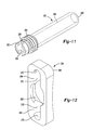
- FIG. 12 is a perspective view of a support pad of the guide assembly of FIG. 10 according to the present teachings
- FIG. 13 is a perspective view of the left-handed outrigger according to the present teachings.
- FIG. 14 is a partial perspective view of the guide assembly of FIG. 10 according to the present teachings.
- FIGS. 15-20B are sequential perspective views of the exemplary guide assembly illustrating use of the guide assembly in various stages of engagement and with alternative combinations of implants according to the present teachings;
- FIG. 21 is a sectional view of an alternative implant assembly according to the present teachings.
- FIG. 22 is an exploded perspective view of a ligament washer of implant assembly of FIG. 21 according to the present teachings
- FIG. 23 is a perspective view of an exemplary assembled configuration of the ligament washer of FIG. 22 according to the present teachings.
- FIG. 24 is a sectional view of an alternative configuration of the implant assembly of FIG. 21 according to the present teachings.
- FIG. 25 is a sectional view of another alternative configuration of the implant assembly of FIG. 21 according to the present teachings.
- the guide assembly of the present teachings can be used with any type of prosthesis for a bone, such as, for example, a proximal or distal femur, a proximal or distal tibia, a proximal or distal humerus, etc.
- the lateral implants can include various types of implants such as, for example, a lateral augment or a claw plate, or combinations thereof. Therefore, it will be understood that the following discussions are not intended to limit the scope of the appended claims.
- an exemplary implant 10 can include a proximal femoral body implant 12 and a lateral support implant or claw plate 14 .
- the proximal femoral body 12 can define a longitudinal bore 16 extending from a proximal end 18 along a longitudinal axis A and a blind bore 20 extending from a lateral side 22 towards a medial side 24 without surfacing on medial side 24 and having a longitudinal axis B.
- Blind bore 20 can be positioned at an acute angle ⁇ relative to longitudinal axis A.
- blind bore 20 is shown as extending at an acute angle relative to longitudinal axis A, it should be appreciated that angle ⁇ can include various angles as may be desirable for different femoral body implant configurations.
- Bore 20 can include a threaded portion 26 and longitudinal bore 16 can also include a threaded portion 28 adjacent proximal end 18 .
- Proximal femoral body 12 can also include a neck portion 34 and a distal end 36 having a bore 38 .
- Neck portion 34 can include a distal end 40 for receiving a spherical femoral head 42 that can mate with an acetabular cup 44 , as shown in FIGS. 1 and 2 .
- the femoral head 42 can be coupled to the neck portion 34 with a tapered connection, such as a Morse taper connection.
- Distal end bore 38 can include a female tapered configuration 46 that is configured to matingly receive a corresponding proximal male tapered end 50 of a distal stem extension 52 of implant 10 .
- Tapered end 50 can include a blind threaded bore 54 configured to receive fastener 56 therein.
- the implant 10 can further include a lateral fastener, such as a trochanteric bolt 60 , having a threaded end 62 and a head 64 .
- a lateral fastener such as a trochanteric bolt 60
- Trochanteric bolt 60 can be inserted into the lateral blind bore 20 from a lateral side 68 of the femur 70 through a lateral bore 72 drilled into femur 70 .
- Lateral bore 72 can be coaxial with blind bore 20 and can be drilled into femur 70 using guide assembly 200 of FIG. 10 , as will be described in more detail below.
- the threaded end 62 of trochanteric bolt 60 can engage threaded portion 26 of blind bore 20 .
- the claw plate 14 can be implanted laterally in soft tissue 80 adjacent to the femur 70 with the assistance of the guide assembly 200 , as will also be described below in greater detail.
- Claw plate 14 can be used to provide support for soft tissue and/or a bone fragment, such as a portion 84 of a greater trochanter that has been broken off or resected, which may be required during a revision hip replacement procedure.
- the claw plate 14 can be retained in position by the head 64 of trochanteric bolt 60 , with the head 64 being received in a countersunk bore 88 of claw plate 14 , as shown in FIGS. 1-3 .
- the claw plate 14 can have a variety of shapes depending on the particular application and can also be anatomically configured so as to have a shape that substantially conforms to the shape of the lateral side 68 of the femur 70 or the greater trochanter bone portion 84 .
- the claw plate 14 can also include anchors or soft tissue piercing spikes 92 for soft tissue attachment.
- the proximal femoral body 12 can be coupled to the distal stem extension 52 with a Morse taper connection 96 such that the tapered proximal end 50 of the stem extension 52 is press fitted into the tapered distal bore 38 of proximal femoral body 12 .
- the proximal femoral body 12 can be at least partially received in an intramedullary canal 98 of the femur 70 .
- the distal stem extension 52 can also be locked to the proximal body 12 by fastener 56 being received in longitudinal bore 16 of proximal body 12 and engaging threaded bore 54 of stem extension 52 .
- the proximal femoral body 12 and distal stem 52 can be implanted using a minimally invasive procedure or technique through a small anterior or posterior incision adjacent the left or right femur.
- implant 10 can also include lateral augments, such as lateral augments 102 , 104 , as may be required during a revision hip replacement procedure to provide for proper trochanter attachment.
- lateral augments such as lateral augments 102 , 104
- the augments 102 , 104 can act as spacers to provide appropriate adjustment for the location of attachment of the trochanter to the proximal femoral body 12 , as shown for example in FIG. 3A .
- the lateral augments 102 , 104 can also be used during a revision hip replacement procedure to compensate for any bone loss adjacent the lateral side of the hip implant.
- lateral augment 102 can include a substantially T-shaped configuration 108 having a body portion 110 with a lateral bone engaging surface 112 and a medial implant facing surface 114 , and a cylindrical or tubular portion 118 extending from medial surface 114 .
- Tubular portion 118 can include a tapered exterior surface 120 configured to be received in a mating tapered counterbore 124 formed into proximal femoral implant body 12 , as generally shown in FIG. 5 .
- the tapered exterior surface 120 and corresponding tapered counterbore 124 can be configured to provide a Morse taper connection 126 for coupling lateral augment 102 to proximal femoral body 12 .
- Augment 102 can include an aperture 130 extending through body portion 110 and tubular portion 118 for receiving trochanter bolt 60 to secure claw plate 14 and T-shaped augment 102 to proximal femoral body 12 , as generally shown in FIG. 3A .
- Lateral augment 102 can further include a generally arcuate shape 136 corresponding to a mating shape on lateral side 68 of proximal femoral body 12 .
- Lateral augment 102 can be configured with various lengths 138 and thicknesses 140 , as may be required to provide for appropriate trochanter positioning and attachment during the revision hip procedure discussed above.
- Lateral surface 112 can also be provided with a roughened or porous metal coating to enhance biologic fixation, such as a layer of Regenerex® porous titanium construct 142 , available from Biomet, Inc. of Warsaw, Ind.
- lateral augment 102 can be formed entirely out of porous metal.
- lateral augment 104 can include an L-shaped configuration 150 with a lateral surface 152 , a medial surface 154 , a lateral portion 156 and a superior portion 158 extending from lateral portion 156 .
- Lateral surface 152 can include a layer of porous metal coating, such as the layer of Regenerex® 142 discussed above and as generally shown in FIG. 8A .
- lateral augment 104 can be formed entirely out of porous metal.
- Lateral portion 156 can include a protrusion 160 extending from rear surface 154 and configured to engage a correspondingly shaped recess 162 in the proximal femoral body 12 , as shown in FIGS. 8B and 9 .
- the claw plate 14 can be implanted using guide assembly 200 .
- guide assembly 200 can provide for forming the lateral bore 72 and inserting the trochanteric bolt 60 therethrough and into engagement with the proximal femoral body 12 after the proximal body has been implanted in femur 70 .
- Guide assembly 200 can include an exemplary left-handed outrigger 210 that can take the form of a C-shaped arm 212 , a leg or base portion 214 extending from a first or lateral end 218 of C-shaped arm 212 , and a bore 220 ( FIG. 13 ) extending through a second or medial end 222 of C-shaped arm 212 .
- Outrigger 210 can be sized to be substantially rigid so as to avoid misalignment due to bending or flexing, and can be configured with the C-shape 212 to avoid the abductor muscles 223 of the hip joint during implantation of the trochanter bolt 60 , claw plate 14 and one of the lateral augments 102 , 104 , if required.
- the left-handed outrigger 210 can be used laterally with anterior incisions of the left femur area or posterior incisions of the right femur area. It will be appreciated that while outrigger 210 is shown in FIG. 10 as well as all other applicable Figures in a “left-handed” configuration, the outrigger 210 can also be configured in a “right handed” configuration, which is a mirror image of the “left handed” outrigger 210 . The right-handed outrigger can be used laterally with anterior incisions of the right femur area and/or posterior incisions of the left femur area. Therefore, it will be understood that while the remaining description will focus on the left-handed outrigger 210 , the description is similarly applicable to the mirror-image right-handed outrigger.
- Medial end 222 of C-shaped arm 212 can further include a slot-like protrusion 224 extending therefrom and configured to be received in a corresponding slot 226 positioned in proximal end 18 of femoral body 12 , as shown in FIGS. 10 and 13 with reference to FIG. 5 .
- the protrusion 224 can be used to align the guide assembly 200 to proximal femoral body 12 before coupling the C-shaped arm 212 thereto with a fastener 228 , as well as to serve as an anti-rotation feature.
- the base portion 214 can include a lateral side 232 and a medial side 234 , as well as a pair of parallel through bores 236 extending through base portion 214 , as shown for example in FIG.
- An alignment tube or sleeve 238 can be integrally formed with base portion 214 or modularly coupled thereto and can be coaxially aligned with another through bore 242 disposed in base portion 214 , as shown in FIGS. 10, 10A and 14 .
- base portion 214 can be parallel to longitudinal axis A and alignment tube 238 can be coaxial with longitudinal axis B of blind bore 20 , as shown for example in FIG. 10 .
- the guide assembly 200 can also include a quick release clamp system 250 , a removable sleeve 252 , and a support pad 254 that cooperates with the clamp system 250 and sleeve 252 .
- the quick-release clamp system 250 can include first and second clamp members 260 , 262 each pivotably coupled to base portion 214 via a hinge pin 264 .
- Each of the clamp members 260 , 262 can have an aperture 266 and an L-shaped configuration 270 that partially wraps around alignment tube 238 , as generally shown in FIG. 10A .
- the apertures 266 can be co-axially aligned with respective through bores 236 in base portion 214 such that each respective aperture 266 and through bore 236 can slidably receive a cylindrical support rod 274 therethrough, as generally shown in FIGS. 10, 13 and 14 .
- a coil spring 278 can be coupled at one end to each clamp member 260 , 262 and at the other end to base portion 214 , as generally shown in FIGS. 10A and 14 .
- the coil springs 278 can have an inner diameter sufficient for receiving one of the supports rods 274 therethrough as well as have an uncompressed length and spring force sufficient to urge respective clamp members 260 , 262 away from base portion 214 to a first or locking position 272 .
- the clamp members 260 , 262 can be positioned at a non-perpendicular angle relative to a longitudinal axis 276 of the cylindrical support rods 274 , as generally shown in FIG. 10A .
- an inner surface 284 of apertures 266 can be misaligned with an exterior surface 286 of each support rod 274 so as to impinge on the support rods via the biasing force imparted by springs 278 .
- the biasing force and resulting impingement of clamp members 260 , 262 on support rods 274 serves to hold each support rod 274 in a desired fixed axial position.
- a user can depress or urge clamp members 260 , 262 towards base portion 214 to a second or release position 280 .
- clamp members 260 , 262 can be perpendicular or substantially perpendicular with longitudinal axis 276 and inner surfaces 284 of apertures 266 can be aligned with support rods 274 .
- support rods 274 can be slidably axially translated relative to the respective clamp member 260 , 262 to a desired position and then the respective clamp member 260 , 262 can be released.
- each of the clamp members 260 , 262 are separate components that can be used to individually or simultaneously adjust and lock a position of a corresponding support rod 274 .
- Such individual adjustment of each support rod 274 can be used, for example, to align support pad 254 flush against claw plate 14 , which can be at various angular orientations relative to the anatomy and longitudinal axis B.
- the removable sleeve 252 can include a first end 290 , a second end 292 and an internal longitudinal bore 294 extending through sleeve 252 .
- the removable sleeve 252 can be received in alignment tube 238 so as to be coaxial therewith and can include an external threaded portion 296 configured to threadingly engage an internal threaded portion 300 of alignment tube 238 , as generally shown in FIGS. 10 and 11 .
- First end 290 of removable sleeve 252 can also include an engagement or drive portion, such as slot 302 , configured to receive a driving tool (not shown) to advance or retract threaded sleeve 252 relative to alignment tube 238 .
- the removable sleeve 252 can receive a trephine or drill 316 in longitudinal bore 294 so as to align and guide drill 316 ( FIG. 17 ) in forming lateral bore 72 .
- Drill 316 can include a stop member, such as an annular collar 318 , positioned on a body 320 of drill 316 configured to abut a first end 324 of alignment tube 238 when drill 316 is inserted into alignment tube 238 and removable sleeve 252 , as will be described in greater detail below.
- the collar 318 can be positioned relative to a tip 328 of drill 316 such that a desired drill depth is achieved when collar 318 abuts alignment tube 238 during a procedure.
- drill 316 can include a plurality of drills 316 each with collar 318 positioned at various distances relative to tip 328 to correspond with different desired drill depths, as may be required, for example, by different size femoral implants 12 and/or the use of lateral augments 102 , 104 .
- a spacer sleeve 336 can be used as an alternative to the above described drill stop member arrangement. More specifically, as an alternative to using various drills 316 each with a differently positioned collar 318 corresponding at least to different implant configurations, one drill 340 can be used along with a plurality of different spacer sleeves 336 , where each spacer sleeve 336 has a length 342 corresponding to a desired drill depth for the various implant configurations.
- Spacer sleeve 336 can include a longitudinal bore 344 configured to receive drill 340 , a first end 346 arranged to abut portion 348 of drill 340 , and a second end 350 configured to abut alignment tube 238 to serve as a stop to limit the drill depth to the predetermined amount that corresponds to the selected spacer sleeve 336 .
- the support pad 254 can include a generally rectangular shape 360 , an aperture 362 for slidably receiving removable sleeve 252 therethrough, and retention slots 364 .
- the support pad 254 can be removable received on circular or spherical engagement members 368 positioned on respective ends of support rods 274 .
- the retention slots 364 can include a generally cylindrical shape 370 with an arcuate surface or periphery 372 that extends for greater than 180 degrees such that the slots 364 can capture the engagement members 368 and couple support pad 254 to support rods 274 .
- the circular or spherical engagement members 368 provide for the ability to orientate the support pad 254 in various angular orientations relative to the support rods 274 .
- one of the lateral augments 102 , 104 can be secured to the lateral side of femoral body 12 , as may be required to provide proper positioning of the greater trochanter relative to proximal femoral body 12 and to account for the above noted bone loss.
- the outrigger 210 can be coupled to the proximal end 18 of proximal femoral body 12 and secured with fastener 228 .
- alignment tube 238 can be coaxially aligned with blind bore 20 , as shown in FIG. 15 .
- the claw plate 14 can then be implanted and compressed against soft tissue 80 adjacent the femur 70 by advancing removable sleeve 252 such that second end 292 engages claw plate 14 , as generally shown in FIGS. 16-17 with reference to FIGS. 1-3B . It should be appreciated that claw plate 14 can be adjusted superiorly or inferiorly relative to longitudinal axis B, as may be required based on various anatomical conditions.
- a suitable driver (not shown) can be coupled to the first end 290 of removable sleeve 252 so as to engage slot 302 and assist in advancing removable sleeve 252 to compress claw plate 14 .
- clamp members 260 , 262 can be independently depressed to release support rods 274 .
- Support rods 274 can then be individually or simultaneously translated forward to engage support pad 254 with claw plate 14 , as shown in FIGS. 16-17 .
- Support pad 254 includes a smooth engagement surface 255 for engaging claw plate 14 ; however, support pad 254 can alternatively include projections 374 that engage slots 90 in claw plate 14 , as also shown in FIG. 17 .
- the appropriately sized drill 316 corresponding to the implanted femoral body 12 and lateral augment 102 , 104 can be inserted into longitudinal bore 294 of removable sleeve 252 to drill the lateral bore 72 into the femur 70 from the lateral side 68 .
- the drill 316 can be advanced until collar 318 engages alignment tube 238 , as shown in FIG. 17 .
- drill 340 could be used with an appropriately selected spacer sleeve 336 to form the lateral bore 72 .
- drill 316 or 340 can be removed from sleeve 252 and an appropriate trochanteric bolt length can be determined by correlating the scribe line 306 with the length designations 310 on alignment tube 238 .
- the length designation 310 aligned with scribe line 306 can correspond to the appropriate trochanteric bolt 60 length required to secure claw plate 14 to blind bore 20 while taking into account the thickness of bone and/or soft tissue being compressed by claw plate 14 .
- the appropriate fastener length can also be determined before bore 72 is formed, such as after claw plate 14 is compressed by advancing removable sleeve 252 .
- sleeve 252 can be removed from alignment tube 238 while support pad 254 continues to compress claw plate 14 in place via support rods 274 , as generally shown in FIG. 19 .
- the selected trochanteric bolt 60 can then be implanted by passing bolt 60 through alignment tube 238 and aperture 362 of support pad 254 such that threaded end 62 engages threaded portion 26 of blind bore 20 .
- Trochanteric bolt 60 can then be tightened such that head 64 engages and secures claw plate 14 , as generally shown in FIGS. 20-20B with reference to FIG. 2-3B .
- the guide assembly 200 can be removed from proximal femoral body 12 .
- Lateral implant 400 can include a generally T-shaped plate member 410 having a proximal end 412 , a distal end 414 , a lateral surface 416 and a medial surface 418 opposite lateral surface 416 .
- the plate member 410 can include a tapered projection 422 extending from medial surface 418 and configured to be received in tapered counterbore 124 of proximal femoral body 12 and coupled thereto via a Morse taper connection 424 .
- An aperture 426 can be provided in plate member 410 extending through projection 422 so as to be coaxial with blind bore 20 when the tapered projection 422 is received in counterbore 124 , as generally shown in FIG. 21 .
- a fastener 428 can be received through aperture 426 and threadingly engaged to bore 20 to secure plate member 410 to proximal femoral body 12 , as generally shown for example in FIG. 21 .
- Plate member 410 can be configured to have a length 432 such that proximal end 414 extends sufficiently beyond proximal end 18 of femoral body 12 so as to provide for adequate soft tissue 80 attachment and support.
- Plate member 410 can also include a layer of porous metal coating, or can alternatively be formed entirely of porous metal.
- a pair of threaded blind bores 444 can be provided in plate member 410 extending from front surface 416 . Bores 444 can be configured to receive a corresponding pair of fasteners 446 for securing soft tissue 80 to a lateral side of plate member 410 , as generally shown in FIG. 21 .
- Proximal end 414 can also include an attachment member, such as a sharp projection or tooth 438 , to assist in attaching and retaining soft tissue 80 .
- plate member 410 can include blind bores 444 extending from the medial surface 418 , as generally shown in FIG. 24 . In this configuration, the soft tissue 80 would be compressed against the medial surface of plate member 410 , as also shown in FIG. 24 . In another alternative configuration, plate member 410 can be angled so as to align with a force generated by the soft tissue, as generally shown in FIG. 25 .
- Lateral implant 400 can also include ligament washers 450 for use with fasteners 446 .
- Each ligament washer 450 can include a body portion 452 and an optional insert 454 configured to abut body portion 452 , as shown in FIGS. 22-23 and generally described in commonly owned co-pending application Ser. No. 12/398,548, entitled “Method and Apparatus for Attaching Soft Tissue to an Implant,” the entirety of which is hereby incorporated by reference herein.
- Body portion 452 can include a fastener engaging side 456 , a soft tissue facing side 458 , an aperture 460 and a plurality of circumferentially spaced ligament engagement members 462 .
- the soft tissue facing side 458 can be configured to engage the soft tissue 80 directly or receive insert 454 .
- Insert 454 can be configured to facilitate biologic fixation and can be coated with a layer of Regenerex® for such purpose.
- insert 454 can be formed entirely of porous metal.
- the plurality of bone engagement members 462 can each include a tapered configuration 464 formed with a base portion 466 attached to the soft tissue facing side 458 and a body portion 468 with multi-faceted side portions 472 that taper to a pointed distal tip 474 .
- Insert 454 can further include a plurality of peripheral cut-outs or recesses 476 corresponding to the plurality of engagement members 462 such that each engagement member 462 is received in a recess 476 , as generally shown in FIGS. 22-23 .
- the ligament washers can be received on fasteners 446 such that the insert 454 and engagement members 462 contact the soft tissue when the fasteners are secured to plate member 410 , as shown in FIGS. 21 and 24-25 .
Abstract
Description
Claims (7)
Priority Applications (2)
| Application Number | Priority Date | Filing Date | Title |
|---|---|---|---|
| US14/563,118 US9510950B2 (en) | 2010-03-05 | 2014-12-08 | Modular lateral hip auguments |
| US15/338,957 US10188520B2 (en) | 2010-03-05 | 2016-10-31 | Modular lateral hip augments |
Applications Claiming Priority (3)
| Application Number | Priority Date | Filing Date | Title |
|---|---|---|---|
| US12/718,230 US8460393B2 (en) | 2010-03-05 | 2010-03-05 | Modular lateral hip augments |
| US13/913,858 US8906109B2 (en) | 2010-03-05 | 2013-06-10 | Modular lateral hip augments |
| US14/563,118 US9510950B2 (en) | 2010-03-05 | 2014-12-08 | Modular lateral hip auguments |
Related Parent Applications (1)
| Application Number | Title | Priority Date | Filing Date |
|---|---|---|---|
| US13/913,858 Division US8906109B2 (en) | 2010-03-05 | 2013-06-10 | Modular lateral hip augments |
Related Child Applications (1)
| Application Number | Title | Priority Date | Filing Date |
|---|---|---|---|
| US15/338,957 Continuation US10188520B2 (en) | 2010-03-05 | 2016-10-31 | Modular lateral hip augments |
Publications (2)
| Publication Number | Publication Date |
|---|---|
| US20150094820A1 US20150094820A1 (en) | 2015-04-02 |
| US9510950B2 true US9510950B2 (en) | 2016-12-06 |
Family
ID=44532009
Family Applications (4)
| Application Number | Title | Priority Date | Filing Date |
|---|---|---|---|
| US12/718,230 Active 2031-06-20 US8460393B2 (en) | 2010-03-05 | 2010-03-05 | Modular lateral hip augments |
| US13/913,858 Active US8906109B2 (en) | 2010-03-05 | 2013-06-10 | Modular lateral hip augments |
| US14/563,118 Active US9510950B2 (en) | 2010-03-05 | 2014-12-08 | Modular lateral hip auguments |
| US15/338,957 Active 2030-05-12 US10188520B2 (en) | 2010-03-05 | 2016-10-31 | Modular lateral hip augments |
Family Applications Before (2)
| Application Number | Title | Priority Date | Filing Date |
|---|---|---|---|
| US12/718,230 Active 2031-06-20 US8460393B2 (en) | 2010-03-05 | 2010-03-05 | Modular lateral hip augments |
| US13/913,858 Active US8906109B2 (en) | 2010-03-05 | 2013-06-10 | Modular lateral hip augments |
Family Applications After (1)
| Application Number | Title | Priority Date | Filing Date |
|---|---|---|---|
| US15/338,957 Active 2030-05-12 US10188520B2 (en) | 2010-03-05 | 2016-10-31 | Modular lateral hip augments |
Country Status (1)
| Country | Link |
|---|---|
| US (4) | US8460393B2 (en) |
Cited By (1)
| Publication number | Priority date | Publication date | Assignee | Title |
|---|---|---|---|---|
| US10188520B2 (en) | 2010-03-05 | 2019-01-29 | Biomet Manufacturing, Llc | Modular lateral hip augments |
Families Citing this family (26)
| Publication number | Priority date | Publication date | Assignee | Title |
|---|---|---|---|---|
| US8579985B2 (en) | 2006-12-07 | 2013-11-12 | Ihip Surgical, Llc | Method and apparatus for hip replacement |
| AU2006351469B2 (en) * | 2006-12-07 | 2012-10-18 | Ihip Surgical, Llc | Method and apparatus for total hip replacement |
| US8974540B2 (en) | 2006-12-07 | 2015-03-10 | Ihip Surgical, Llc | Method and apparatus for attachment in a modular hip replacement or fracture fixation device |
| US8529569B2 (en) | 2010-03-05 | 2013-09-10 | Biomet Manufacturing, Llc | Method and apparatus for preparing a proximal femur |
| US8221432B2 (en) | 2010-03-05 | 2012-07-17 | Biomet Manufacturing Corp. | Method and apparatus for implanting a modular femoral hip |
| US8333807B2 (en) | 2010-03-05 | 2012-12-18 | Biomet Manufacturing Corp. | Method and apparatus for trialing and implanting a modular femoral hip |
| US8679130B2 (en) | 2010-03-05 | 2014-03-25 | Biomet Manufacturing, Llc | Guide assembly for lateral implants and associated methods |
| US8419743B2 (en) | 2010-03-05 | 2013-04-16 | Biomet Manufacturing Corp. | Assembly tool for modular implants and associated method |
| US8715356B2 (en) * | 2010-04-13 | 2014-05-06 | Biomet Manufacturing, Llc | Prosthetic having a modular soft tissue fixation mechanism |
| US20120123481A1 (en) * | 2010-11-15 | 2012-05-17 | Lin Chih I | Bone fixation device |
| GB201105243D0 (en) | 2011-03-29 | 2011-05-11 | Depuy Ireland | An implant |
| US9011444B2 (en) | 2011-12-09 | 2015-04-21 | Howmedica Osteonics Corp. | Surgical reaming instrument for shaping a bone cavity |
| US20140358242A1 (en) * | 2011-12-14 | 2014-12-04 | Smith & Nephew, Inc. | Implant augment |
| AU2012362279A1 (en) | 2011-12-30 | 2014-07-24 | Howmedica Osteonics Corp. | Systems for preparing bone voids to receive a prosthesis |
| EP2671542A1 (en) * | 2012-06-06 | 2013-12-11 | Universitätsspital Basel | Bone plate for the greater trochanter |
| WO2014031535A1 (en) * | 2012-08-20 | 2014-02-27 | Vargas Joseph R | Trochanter attachment device |
| US9398928B2 (en) * | 2012-09-28 | 2016-07-26 | DePuy Synthes Products, Inc. | Adjustable height arthroplasty plate |
| US8979940B2 (en) * | 2012-12-14 | 2015-03-17 | Biomet Manufacturing, Llc | Modular attachment mechanism in prosthetic implants |
| US10149763B2 (en) | 2015-01-12 | 2018-12-11 | Howmedica Osteonics Corp. | Multipurpose void filling prosthesis |
| JP6426482B2 (en) * | 2015-01-14 | 2018-11-21 | HOYA Technosurgical株式会社 | Surgical instruments |
| JP6162735B2 (en) * | 2015-02-25 | 2017-07-12 | 株式会社オーミック | Bone retainer and osteosynthesis reinforcement provided with the same |
| US10856992B2 (en) * | 2016-04-27 | 2020-12-08 | AOD Holdings, LLC | Implant device(s) including tapered protrusions and method(s) for inserting the same into bone |
| US10251744B2 (en) * | 2017-01-27 | 2019-04-09 | Onkos Surgical, Inc. | Soft tissue fixation device |
| US10945850B2 (en) * | 2018-10-25 | 2021-03-16 | Revision Technologies Llc | Interconnected implants and methods |
| CN111134904B (en) * | 2018-11-06 | 2022-03-01 | 贵州澳特拉斯科技有限公司 | Bionic artificial hip joint |
| US11918475B2 (en) | 2021-03-31 | 2024-03-05 | DePuy Synthes Products, Inc. | Modular acetabular surgical implant assembly |
Citations (153)
| Publication number | Priority date | Publication date | Assignee | Title |
|---|---|---|---|---|
| US1714684A (en) | 1927-06-20 | 1929-05-28 | Eastern Machine Screw Corp | Rod-feeding device |
| US2231864A (en) | 1938-08-23 | 1941-02-18 | Cora B Korrer | Attachment for drilling machines |
| US3815599A (en) | 1973-03-02 | 1974-06-11 | W Deyerle | Femoral shaft surgical rasp for use in hip prosthesis surgery |
| US4012796A (en) | 1975-09-24 | 1977-03-22 | Howmedica, Inc. | Interpositioning collar for prosthetic bone insert |
| US4306550A (en) | 1980-02-06 | 1981-12-22 | Minnesota Mining And Manufacturing Company | Combination including femoral rasp and calcar facing reamer |
| US4535487A (en) | 1983-01-18 | 1985-08-20 | Robert Bosch Gmbh | Endoprosthesis shaft |
| US4549319A (en) | 1982-08-03 | 1985-10-29 | United States Medical Corporation | Artificial joint fixation to bone |
| US4552136A (en) | 1983-10-19 | 1985-11-12 | Howmedica, Inc. | Femoral rasp |
| US4601289A (en) | 1985-04-02 | 1986-07-22 | Dow Corning Wright | Femoral trial prosthesis/rasp assembly |
| US4718915A (en) | 1985-03-27 | 1988-01-12 | Epinette Jean Alain | Femoral component of a hip prosthesis |
| US4728333A (en) | 1985-04-05 | 1988-03-01 | Masse Andre A | Modular prosthesis kit |
| US4770660A (en) | 1987-01-20 | 1988-09-13 | Osteonics Corp. | Femoral prosthesis with selectively removable collar |
| US4790852A (en) | 1986-09-15 | 1988-12-13 | Joint Medical Products Corporation | Sleeves for affixing artificial joints to bone |
| US4842606A (en) | 1986-03-15 | 1989-06-27 | Mecron Medizinische Produkte Gmbh | Bone implant |
| US4883492A (en) | 1987-06-23 | 1989-11-28 | Sulzer Brothers Limited | Metal bone implant |
| US4904269A (en) | 1986-10-25 | 1990-02-27 | Paulo Gallinaro | Hip joint prosthesis |
| US4959066A (en) | 1989-02-24 | 1990-09-25 | Zimmer, Inc. | Femoral osteotomy guide assembly |
| US5041118A (en) | 1989-04-28 | 1991-08-20 | Implant Technology Inc. | Femoral broach |
| US5047035A (en) | 1990-08-10 | 1991-09-10 | Mikhail Michael W E | System for performing hip prosthesis revision surgery |
| US5061271A (en) | 1989-02-27 | 1991-10-29 | Boehringer Mannheim Corporation | Tool for separating components of a modular joint prosthesis |
| EP0453695A1 (en) | 1990-04-26 | 1991-10-30 | Monturas S.A. | A spray pump |
| US5080685A (en) | 1986-08-15 | 1992-01-14 | Boehringer Mannheim Corporation | Modular hip prosthesis |
| US5089004A (en) | 1988-01-19 | 1992-02-18 | Osteonics Corp. | Prosthetic implant procedure and femoral broach therefor |
| US5092900A (en) | 1990-03-13 | 1992-03-03 | Sulzer Brothers Limited | Femur head prosthesis |
| US5122146A (en) | 1988-02-04 | 1992-06-16 | Pfizer Hospital Products Group, Inc. | Apparatus for reducing a fracture |
| FR2676172A1 (en) | 1991-05-07 | 1992-11-13 | Fournitures Hospitalieres | Positioning template forming a support reinforcement for a prosthetic cotyle positioned by bayonet assembly |
| US5201769A (en) | 1991-09-23 | 1993-04-13 | Schutzer Steven F | Hip stem with proximal build-up blocks |
| US5211666A (en) | 1991-04-22 | 1993-05-18 | New York University | Hip joint femoral component endoprosthesis with a lateral load-transferring support surface |
| WO1994021199A1 (en) | 1991-02-13 | 1994-09-29 | Howmedica Inc. | Acetabular cup positioning insert with release mechanism |
| DE4320086A1 (en) * | 1993-06-17 | 1994-12-22 | Peter Brehm | Modular shaft for a revision hip prosthesis system |
| US5376124A (en) | 1993-08-03 | 1994-12-27 | Intermedics Orthopedics, Inc. | Collared hip prosthesis with revision spacer |
| US5409492A (en) | 1993-08-09 | 1995-04-25 | Stelkast Incorporated | System for coupling an implant to a tool for inserting and removing the implant |
| US5468243A (en) | 1993-10-27 | 1995-11-21 | Halpern; Alan A. | Femoral superior neck remodelling means and method |
| DE29516473U1 (en) | 1995-10-17 | 1995-12-07 | Keramed Medizintechnik Gmbh | Artificial acetabular cup |
| US5489284A (en) | 1994-07-15 | 1996-02-06 | Smith & Nephew Richards Inc. | Cannulated modular intramedullary nail |
| US5562666A (en) | 1986-12-30 | 1996-10-08 | Smith & Nephew Richards Inc. | Method for treating intertrochanteric fracture utilizing a femoral fracture device |
| GB2299758A (en) | 1995-04-10 | 1996-10-16 | Finsbury | Surgical tool for use in joint replacement |
| FR2732891A1 (en) | 1995-04-12 | 1996-10-18 | Setiey Louis | Femoral prosthesis used in orthopaedics |
| US5571111A (en) | 1995-05-01 | 1996-11-05 | Aboczky; Robert I. | Instrument for orienting, inserting and impacting an acetabular cup prosthesis including prosthesis retaining head arrangement |
| US5578037A (en) | 1994-11-14 | 1996-11-26 | Johnson & Johnson Professional, Inc. | Surgical guide for femoral resection |
| US5601564A (en) | 1993-11-24 | 1997-02-11 | Orthopaedic Innovations, Inc. | Cannulated broach for total joint arthroplasty |
| US5607431A (en) | 1995-02-09 | 1997-03-04 | Howmedica Inc. | Prosthetic hip implantation method and apparatus |
| US5624445A (en) | 1992-11-20 | 1997-04-29 | Burke; Dennis W. | Apparatus for cutting grooves in a bone |
| US5632747A (en) | 1995-03-15 | 1997-05-27 | Osteotech, Inc. | Bone dowel cutter |
| US5645549A (en) | 1995-04-24 | 1997-07-08 | Danek Medical, Inc. | Template for positioning interbody fusion devices |
| US5649930A (en) | 1996-01-26 | 1997-07-22 | Kertzner; Richard I. | Orthopedic centering tool |
| US5665090A (en) | 1992-09-09 | 1997-09-09 | Dupuy Inc. | Bone cutting apparatus and method |
| US5683470A (en) | 1995-02-15 | 1997-11-04 | Smith & Nephew, Inc. | Tibial trial prosthesis and bone preparation system |
| US5690636A (en) | 1995-12-21 | 1997-11-25 | Johnson & Johnson Professional, Inc. | Punch system for tibial prosthesis |
| US5699915A (en) | 1993-12-21 | 1997-12-23 | Berger Mix Inc. | Palletized peat moss in bulk compressed form |
| US5704940A (en) | 1995-10-03 | 1998-01-06 | Garosi; Piero | Instrument set for preparation of the seat for the femoral component of a non-cemented hip prosthesis |
| US5766262A (en) | 1996-03-29 | 1998-06-16 | Mikhail; W. E. Michael | Femoral prosthesis with spacer |
| US5766261A (en) | 1996-02-01 | 1998-06-16 | Osteonics Corp. | Femoral revision broach with modular trial components and method |
| US5776194A (en) | 1996-04-25 | 1998-07-07 | Nuvana Medical Innovations, Llc | Intermedullary rod apparatus and methods of repairing proximal humerus fractures |
| US5788701A (en) | 1995-12-21 | 1998-08-04 | Johnson & Johnson Professional, Inc. | Instrument system for knee prothesis implantation with universal handle or slap hammer |
| US5849015A (en) | 1997-09-11 | 1998-12-15 | Bristol-Myers Squibb Company | Orthopaedic stem inserter with quick release lever and ratchet |
| US5860982A (en) | 1997-03-26 | 1999-01-19 | Johnson & Johnson Professional, Inc. | Cemented calcar replacement varying height trial |
| US5860969A (en) | 1997-04-30 | 1999-01-19 | Biomet, Inc. | Version adjustment instrument for modular femoral components and method of using same |
| US5908423A (en) | 1993-05-27 | 1999-06-01 | Howmedica, Inc. | Flexible medullary reaming system |
| US5913860A (en) | 1998-02-27 | 1999-06-22 | Synthes (Usa) | Surgical nail inserter |
| US5976145A (en) | 1998-06-01 | 1999-11-02 | Johnson & Johnson Professional, Inc. | Calcar milling guide and system |
| US5989261A (en) | 1997-03-13 | 1999-11-23 | Zimmer, Ltd. | Evaluating the fit of an orthopaedic implant |
| US6022357A (en) | 1997-03-03 | 2000-02-08 | Aesculap Ag & Co. Kg | Surgical instrument |
| US6027505A (en) | 1997-07-04 | 2000-02-22 | Sulzer Orthopaedie Ag | Instrument for the introduction of an inlay of an implant into the associated shell |
| US6033405A (en) | 1994-09-15 | 2000-03-07 | Surgical Dynamics, Inc. | Apparatus and method for implant insertion |
| US6066173A (en) | 1998-01-28 | 2000-05-23 | Ethicon, Inc. | Method and apparatus for fixing a graft in a bone tunnel |
| US6110179A (en) | 1998-03-02 | 2000-08-29 | Benoist Girard Sas | Prosthesis inserter |
| US6110211A (en) | 1998-05-01 | 2000-08-29 | Weiss; James M. | Hip replacement methods and apparatus |
| US6113604A (en) | 1997-01-14 | 2000-09-05 | Ethicon, Inc. | Method and apparatus for fixing a graft in a bone tunnel |
| US6117173A (en) | 1995-12-07 | 2000-09-12 | Aesculap Ag & Co., Kg | Orthopaedic fixing system |
| US6117138A (en) | 1999-04-16 | 2000-09-12 | Sulzer Orthopedics Inc. | Instruments for forming bony cavity for implantable femoral, hip prosthesis |
| US6126694A (en) | 1999-03-05 | 2000-10-03 | Sulzer Orthopedics Inc. | Universal distal broach and stem trial |
| US6136035A (en) | 1994-11-19 | 2000-10-24 | Merck Patent Gmbh | Modular joint prosthesis |
| US6139551A (en) | 1995-06-07 | 2000-10-31 | Sdgi Holdings, Inc. | Anterior spinal instrumentation and method for implantation and revision |
| FR2792822A1 (en) | 1999-04-27 | 2000-11-03 | Caffiniere Jean Yves De | Osteosynthesis device for fixing large trochanter on femoral piece of hip prothesis comprises clip, variable length socket and screw |
| US6143030A (en) | 1999-03-26 | 2000-11-07 | Bristol-Myers Squibb Co. | Impaction allograft form and method of orthopaedic surgery using same |
| US6152963A (en) | 1996-01-04 | 2000-11-28 | Joint Medical Products Corporation | Method and apparatus for fitting a prosthesis to a bone |
| US6159216A (en) | 1998-09-09 | 2000-12-12 | Sulzer Orthopedics Inc. | Combination tibial preparation instrumentation |
| US6206884B1 (en) | 1998-07-15 | 2001-03-27 | Medidea, Llc | Reduction-based joint replacement apparatus and methods |
| US6224605B1 (en) | 1999-11-24 | 2001-05-01 | Bristol-Myers Squibb Co. | Orthopaedic instrumentation assembly and method of using same |
| US6224609B1 (en) | 1998-03-16 | 2001-05-01 | Teramed Inc. | Bifurcated prosthetic graft |
| US6238435B1 (en) | 2000-03-10 | 2001-05-29 | Bristol-Myers Squibb Co | Assembly tool for prosthetic implant |
| US6245111B1 (en) | 1997-05-12 | 2001-06-12 | Richard L. Shaffner | Method and apparatus for fighting infection and maintaining joint spacing in a prosthesis implant area |
| US6267785B1 (en) | 1996-02-01 | 2001-07-31 | Medidea, Llc | Apparatus for positioning a prosthetic element to achieve a desired orientation for cementation |
| US6302890B1 (en) | 2000-03-16 | 2001-10-16 | Leone Innovations Corporation | Pelvic alignment assembly |
| US6306174B1 (en) | 1998-12-18 | 2001-10-23 | Benoist Girard Sas | Femoral component |
| US6325804B1 (en) | 2000-06-28 | 2001-12-04 | Ethicon, Inc. | Method for fixing a graft in a bone tunnel |
| US6330845B1 (en) | 2000-05-17 | 2001-12-18 | Bristol-Myers Squibb | Wrench for an implant |
| US6338734B1 (en) | 2000-03-14 | 2002-01-15 | Biomet, Inc. | Method and apparatus for trochanter fixation |
| US6344060B1 (en) | 1998-09-10 | 2002-02-05 | Plus Endoprothetik Ag | Kit for implanting a cementable endoprosthesis |
| US6361565B1 (en) | 1991-08-12 | 2002-03-26 | Peter M. Bonutti | Expandable hip implant |
| US6371991B1 (en) | 1996-12-23 | 2002-04-16 | Depuy Orthopaedics, Inc. | Alignment guide for fluted prosthetic stems |
| US6395004B1 (en) | 1997-11-14 | 2002-05-28 | Sulzer Orthopedics Inc. | Orthopedic trial prosthesis and saw guide instrument |
| US6468281B1 (en) | 1998-04-30 | 2002-10-22 | Ceramtec Ag | Instrument for manipulating components of joint prostheses |
| US6517581B2 (en) | 2001-01-25 | 2003-02-11 | Zimmer, Inc. | Method and apparatus for preparing a femur to receive a modular prosthetic femoral component |
| US6626913B1 (en) | 1999-03-03 | 2003-09-30 | Smith & Nephew, Inc. | Methods, systems, and instruments for inserting prosthetic implants |
| US20030233100A1 (en) | 2002-06-12 | 2003-12-18 | Michael Santarella | Modular hip inserter/positioner |
| US20040107001A1 (en) | 1999-06-01 | 2004-06-03 | Cheal Edward J. | Joint prostheses and components thereof |
| US20040122439A1 (en) | 2002-12-20 | 2004-06-24 | Dwyer Kimberly A. | Adjustable biomechanical templating & resection instrument and associated method |
| US20040236341A1 (en) | 2003-05-20 | 2004-11-25 | Petersen Thomas D. | Instruments and method for minimally invasive surgery for total hips |
| US20040267267A1 (en) | 2003-06-25 | 2004-12-30 | Daniels David Wayne | Non-linear reamer for bone preparation and associated method |
| US6871549B2 (en) | 2002-05-09 | 2005-03-29 | Michael A. Serra | Modular implant assembly tool |
| US6875239B2 (en) | 2002-04-25 | 2005-04-05 | Medicinelodge, Inc. | Modular prosthesis for replacing bone and method |
| US6883217B2 (en) | 2002-12-13 | 2005-04-26 | Zimmer Technology, Inc. | Apparatus for disassembling mating taper connections |
| US6913623B1 (en) | 2000-08-15 | 2005-07-05 | Centerpulse Orthopedics, Inc. | Two piecefused femoral hip stem |
| US20050149042A1 (en) | 2003-01-15 | 2005-07-07 | Robert Metzger | Instrumentation for knee resection |
| US6932819B2 (en) | 1997-03-19 | 2005-08-23 | Stryker Trauma Sa | Modular intramedullary nail |
| US20050203539A1 (en) | 2004-03-08 | 2005-09-15 | Grimm James E. | Navigated stemmed orthopaedic implant inserter |
| US20050234463A1 (en) | 2004-01-05 | 2005-10-20 | Hershberger Troy W | Method and instrumentation for performing minimally invasive hip arthroplasty |
| US20060004459A1 (en) | 2004-06-30 | 2006-01-05 | Hazebrouck Stephen A | Adjustable orthopaedic prosthesis and associated method |
| US7074224B2 (en) | 2003-06-25 | 2006-07-11 | Depuy Products, Inc. | Modular tapered reamer for bone preparation and associated method |
| US7179259B1 (en) | 2004-06-04 | 2007-02-20 | Biomet Manufacturing Corp. | Instrument assembly for lateral implant |
| US20070093844A1 (en) | 2005-10-12 | 2007-04-26 | Dye Donald W | Calcar planers for minimally invasive surgery |
| US7210881B2 (en) | 2003-12-30 | 2007-05-01 | Greenberg Alex M | Sleeved stop for a drill bit |
| US20070123908A1 (en) | 2003-06-25 | 2007-05-31 | Depuy Products, Inc. | Assembly tool for modular implants, kit and associated method |
| US20070129809A1 (en) | 2005-12-05 | 2007-06-07 | Biomet Manufacturing Corp. | Apparatus for use of porous implants |
| US7247171B2 (en) | 2002-03-11 | 2007-07-24 | Sotereanos Nicholas G | Modular hip implants |
| US7255716B2 (en) | 2002-05-09 | 2007-08-14 | Pubols Steven C | Method and instruments for inserting modular implant components |
| US7261741B2 (en) | 2001-06-30 | 2007-08-28 | Depuy Products, Inc. | Prosthesis with resorbable collar |
| WO2007106752A2 (en) | 2006-03-10 | 2007-09-20 | Smith & Nephew, Inc. | Femoral reaming system with trial neck |
| US20070233127A1 (en) | 2005-09-19 | 2007-10-04 | Finsbury (Development) Limited | Medical Tool for Hard Tissue Bores |
| US7291176B2 (en) | 2002-05-09 | 2007-11-06 | Hayes Medical, Inc. | System for establishing the orientation of a modular implant |
| US7296804B2 (en) | 2000-06-24 | 2007-11-20 | Precimed S.A. | Hand-held instrument holder for surgical use |
| US7297166B2 (en) | 2003-06-25 | 2007-11-20 | Depuy Products, Inc. | Assembly tool for modular implants and associated method |
| US7341589B2 (en) | 1999-09-13 | 2008-03-11 | Synthes (U.S.A.) | Bone plating system |
| US20080125867A1 (en) | 2006-11-28 | 2008-05-29 | Depuy Products, Inc. | Modular proximal body trial |
| US20080161811A1 (en) | 2006-09-29 | 2008-07-03 | Depuy Products, Inc. | Proximal reamer |
| US20080208203A1 (en) | 2007-02-26 | 2008-08-28 | Benoist Girard Sas | Bone measurement device |
| US7425214B1 (en) | 2005-03-03 | 2008-09-16 | Howmedica Osteonics Corp. | Hip arthroplasty trialing apparatus with adjustable proximal trial and method |
| US20080234685A1 (en) | 2004-05-18 | 2008-09-25 | Scandinavian Customized Prosthesis Asa | Patient-Adapted Osteotomy Template for Precise Resection of the Neck of the Femur in a Total Hip Prosthesis Operation |
| US20080243133A1 (en) | 2007-02-27 | 2008-10-02 | Warsaw Orthopedic, Inc. | Surgical Driver |
| US20080243190A1 (en) | 2007-03-29 | 2008-10-02 | Depuy Spine, Inc. | In-line rod reduction device and methods |
| US20080269765A1 (en) | 2007-04-27 | 2008-10-30 | Zimmer, Inc. | Instrument and method for implanting a prosthetic component |
| US20080281428A1 (en) | 2007-05-07 | 2008-11-13 | Zimmer, Inc. | Methods and apparatuses for attaching soft tissue to orthopaedic implants |
| US20080294168A1 (en) | 2007-05-23 | 2008-11-27 | Stryker Trauma Gmbh | Reaming device |
| US7491242B2 (en) | 2003-03-10 | 2009-02-17 | Benoist Girard Sas | Femoral prosthesis |
| US20090099566A1 (en) | 2007-10-10 | 2009-04-16 | Maness Megan A | Modular stem inserter |
| US20090112218A1 (en) | 2007-10-31 | 2009-04-30 | Mccleary Larry G | Modular taper assembly device |
| US7582092B2 (en) | 2003-06-25 | 2009-09-01 | Depuy Products, Inc. | Assembly tool for modular implants and associated method |
| US20090265014A1 (en) | 2008-04-22 | 2009-10-22 | Biomet Manufacturing Corp. | Method And Apparatus For Attaching Soft Tissue To An Implant |
| US20090270866A1 (en) | 2008-04-28 | 2009-10-29 | Didier Poncet | Variable offset reamer assembly for modular humeral component |
| US7832405B1 (en) | 2004-08-25 | 2010-11-16 | Biomet Manufacturing Corp. | Method and apparatus for assembling implants |
| US7857858B2 (en) | 2002-04-25 | 2010-12-28 | Zimmer Technology, Inc. | Modular bone implant, tool, and method |
| US20110015634A1 (en) | 2009-07-14 | 2011-01-20 | Biomet Manufacturing Corp. | Modular Reaming System for Femoral Revision |
| US7887539B2 (en) | 2003-01-24 | 2011-02-15 | Depuy Spine, Inc. | Spinal rod approximators |
| US20110046745A1 (en) | 2002-12-20 | 2011-02-24 | Depuy Products, Inc. | Instrument and associated method of trialing for modular hip stems |
| US20110218583A1 (en) | 2010-03-05 | 2011-09-08 | Biomet Manufacturing Corp. | Assembly Tool for Modular Implants and Associated Method |
| US20110218537A1 (en) | 2010-03-05 | 2011-09-08 | Biomet Manufacturing Corp. | Method and Apparatus for Preparing a Proximal Femur |
| US20110218636A1 (en) | 2010-03-05 | 2011-09-08 | Biomet Manufacturing Corp. | Guide Assembly for Lateral Implants and Associated Methods |
| US20110218641A1 (en) | 2010-03-05 | 2011-09-08 | Biomet Manufacturing Corp. | Modular Lateral Hip Augments |
| US8221432B2 (en) | 2010-03-05 | 2012-07-17 | Biomet Manufacturing Corp. | Method and apparatus for implanting a modular femoral hip |
| US8226725B2 (en) | 2009-09-01 | 2012-07-24 | Howmedica Osteonics Corp. | Prosthesis having a soft tissue attachment element |
| US8333807B2 (en) | 2010-03-05 | 2012-12-18 | Biomet Manufacturing Corp. | Method and apparatus for trialing and implanting a modular femoral hip |
Family Cites Families (5)
| Publication number | Priority date | Publication date | Assignee | Title |
|---|---|---|---|---|
| US2511051A (en) * | 1946-06-19 | 1950-06-13 | Dzus William | Fastening device |
| US3489143A (en) * | 1967-12-15 | 1970-01-13 | William X Halloran | Convertible hip pin |
| JP2005315902A (en) * | 2004-04-26 | 2005-11-10 | Seiko Epson Corp | Optical connector |
| US7505732B2 (en) * | 2004-12-22 | 2009-03-17 | Fmr Llc | Broadcasting user-specific information |
| US8308806B2 (en) * | 2007-01-11 | 2012-11-13 | Depuy Products, Inc. | Orthopaedic stem with protrusion and associated surgical procedure |
-
2010
- 2010-03-05 US US12/718,230 patent/US8460393B2/en active Active
-
2013
- 2013-06-10 US US13/913,858 patent/US8906109B2/en active Active
-
2014
- 2014-12-08 US US14/563,118 patent/US9510950B2/en active Active
-
2016
- 2016-10-31 US US15/338,957 patent/US10188520B2/en active Active
Patent Citations (173)
| Publication number | Priority date | Publication date | Assignee | Title |
|---|---|---|---|---|
| US1714684A (en) | 1927-06-20 | 1929-05-28 | Eastern Machine Screw Corp | Rod-feeding device |
| US2231864A (en) | 1938-08-23 | 1941-02-18 | Cora B Korrer | Attachment for drilling machines |
| US3815599A (en) | 1973-03-02 | 1974-06-11 | W Deyerle | Femoral shaft surgical rasp for use in hip prosthesis surgery |
| US4012796A (en) | 1975-09-24 | 1977-03-22 | Howmedica, Inc. | Interpositioning collar for prosthetic bone insert |
| US4306550A (en) | 1980-02-06 | 1981-12-22 | Minnesota Mining And Manufacturing Company | Combination including femoral rasp and calcar facing reamer |
| US4549319A (en) | 1982-08-03 | 1985-10-29 | United States Medical Corporation | Artificial joint fixation to bone |
| US4535487A (en) | 1983-01-18 | 1985-08-20 | Robert Bosch Gmbh | Endoprosthesis shaft |
| US4552136A (en) | 1983-10-19 | 1985-11-12 | Howmedica, Inc. | Femoral rasp |
| US4718915A (en) | 1985-03-27 | 1988-01-12 | Epinette Jean Alain | Femoral component of a hip prosthesis |
| US4601289A (en) | 1985-04-02 | 1986-07-22 | Dow Corning Wright | Femoral trial prosthesis/rasp assembly |
| US4728333A (en) | 1985-04-05 | 1988-03-01 | Masse Andre A | Modular prosthesis kit |
| US4842606A (en) | 1986-03-15 | 1989-06-27 | Mecron Medizinische Produkte Gmbh | Bone implant |
| US5080685A (en) | 1986-08-15 | 1992-01-14 | Boehringer Mannheim Corporation | Modular hip prosthesis |
| US4790852A (en) | 1986-09-15 | 1988-12-13 | Joint Medical Products Corporation | Sleeves for affixing artificial joints to bone |
| US4904269A (en) | 1986-10-25 | 1990-02-27 | Paulo Gallinaro | Hip joint prosthesis |
| US5562666A (en) | 1986-12-30 | 1996-10-08 | Smith & Nephew Richards Inc. | Method for treating intertrochanteric fracture utilizing a femoral fracture device |
| US4770660A (en) | 1987-01-20 | 1988-09-13 | Osteonics Corp. | Femoral prosthesis with selectively removable collar |
| US4883492A (en) | 1987-06-23 | 1989-11-28 | Sulzer Brothers Limited | Metal bone implant |
| US5089004A (en) | 1988-01-19 | 1992-02-18 | Osteonics Corp. | Prosthetic implant procedure and femoral broach therefor |
| US5122146A (en) | 1988-02-04 | 1992-06-16 | Pfizer Hospital Products Group, Inc. | Apparatus for reducing a fracture |
| US4959066A (en) | 1989-02-24 | 1990-09-25 | Zimmer, Inc. | Femoral osteotomy guide assembly |
| US5061271A (en) | 1989-02-27 | 1991-10-29 | Boehringer Mannheim Corporation | Tool for separating components of a modular joint prosthesis |
| US5041118A (en) | 1989-04-28 | 1991-08-20 | Implant Technology Inc. | Femoral broach |
| US5092900A (en) | 1990-03-13 | 1992-03-03 | Sulzer Brothers Limited | Femur head prosthesis |
| EP0453695A1 (en) | 1990-04-26 | 1991-10-30 | Monturas S.A. | A spray pump |
| US5047035A (en) | 1990-08-10 | 1991-09-10 | Mikhail Michael W E | System for performing hip prosthesis revision surgery |
| WO1994021199A1 (en) | 1991-02-13 | 1994-09-29 | Howmedica Inc. | Acetabular cup positioning insert with release mechanism |
| US5211666A (en) | 1991-04-22 | 1993-05-18 | New York University | Hip joint femoral component endoprosthesis with a lateral load-transferring support surface |
| FR2676172A1 (en) | 1991-05-07 | 1992-11-13 | Fournitures Hospitalieres | Positioning template forming a support reinforcement for a prosthetic cotyle positioned by bayonet assembly |
| US6361565B1 (en) | 1991-08-12 | 2002-03-26 | Peter M. Bonutti | Expandable hip implant |
| US5201769A (en) | 1991-09-23 | 1993-04-13 | Schutzer Steven F | Hip stem with proximal build-up blocks |
| US5665090A (en) | 1992-09-09 | 1997-09-09 | Dupuy Inc. | Bone cutting apparatus and method |
| US5624445A (en) | 1992-11-20 | 1997-04-29 | Burke; Dennis W. | Apparatus for cutting grooves in a bone |
| US5908423A (en) | 1993-05-27 | 1999-06-01 | Howmedica, Inc. | Flexible medullary reaming system |
| DE4320086A1 (en) * | 1993-06-17 | 1994-12-22 | Peter Brehm | Modular shaft for a revision hip prosthesis system |
| US5376124A (en) | 1993-08-03 | 1994-12-27 | Intermedics Orthopedics, Inc. | Collared hip prosthesis with revision spacer |
| US5409492A (en) | 1993-08-09 | 1995-04-25 | Stelkast Incorporated | System for coupling an implant to a tool for inserting and removing the implant |
| US5468243A (en) | 1993-10-27 | 1995-11-21 | Halpern; Alan A. | Femoral superior neck remodelling means and method |
| US5601564A (en) | 1993-11-24 | 1997-02-11 | Orthopaedic Innovations, Inc. | Cannulated broach for total joint arthroplasty |
| US5699915A (en) | 1993-12-21 | 1997-12-23 | Berger Mix Inc. | Palletized peat moss in bulk compressed form |
| US5489284A (en) | 1994-07-15 | 1996-02-06 | Smith & Nephew Richards Inc. | Cannulated modular intramedullary nail |
| US6033405A (en) | 1994-09-15 | 2000-03-07 | Surgical Dynamics, Inc. | Apparatus and method for implant insertion |
| US5578037A (en) | 1994-11-14 | 1996-11-26 | Johnson & Johnson Professional, Inc. | Surgical guide for femoral resection |
| US6136035A (en) | 1994-11-19 | 2000-10-24 | Merck Patent Gmbh | Modular joint prosthesis |
| US5607431A (en) | 1995-02-09 | 1997-03-04 | Howmedica Inc. | Prosthetic hip implantation method and apparatus |
| US5683470A (en) | 1995-02-15 | 1997-11-04 | Smith & Nephew, Inc. | Tibial trial prosthesis and bone preparation system |
| US5632747A (en) | 1995-03-15 | 1997-05-27 | Osteotech, Inc. | Bone dowel cutter |
| GB2299758A (en) | 1995-04-10 | 1996-10-16 | Finsbury | Surgical tool for use in joint replacement |
| FR2732891A1 (en) | 1995-04-12 | 1996-10-18 | Setiey Louis | Femoral prosthesis used in orthopaedics |
| US5645549A (en) | 1995-04-24 | 1997-07-08 | Danek Medical, Inc. | Template for positioning interbody fusion devices |
| US5571111A (en) | 1995-05-01 | 1996-11-05 | Aboczky; Robert I. | Instrument for orienting, inserting and impacting an acetabular cup prosthesis including prosthesis retaining head arrangement |
| USRE37005E (en) | 1995-06-07 | 2000-12-26 | Sdgi Holdings, Inc. | Anterior spinal instrumentation and method for implantation and revision |
| US6139551A (en) | 1995-06-07 | 2000-10-31 | Sdgi Holdings, Inc. | Anterior spinal instrumentation and method for implantation and revision |
| US5704940A (en) | 1995-10-03 | 1998-01-06 | Garosi; Piero | Instrument set for preparation of the seat for the femoral component of a non-cemented hip prosthesis |
| DE29516473U1 (en) | 1995-10-17 | 1995-12-07 | Keramed Medizintechnik Gmbh | Artificial acetabular cup |
| US6117173A (en) | 1995-12-07 | 2000-09-12 | Aesculap Ag & Co., Kg | Orthopaedic fixing system |
| US5788701A (en) | 1995-12-21 | 1998-08-04 | Johnson & Johnson Professional, Inc. | Instrument system for knee prothesis implantation with universal handle or slap hammer |
| US5690636A (en) | 1995-12-21 | 1997-11-25 | Johnson & Johnson Professional, Inc. | Punch system for tibial prosthesis |
| US6152963A (en) | 1996-01-04 | 2000-11-28 | Joint Medical Products Corporation | Method and apparatus for fitting a prosthesis to a bone |
| US5649930A (en) | 1996-01-26 | 1997-07-22 | Kertzner; Richard I. | Orthopedic centering tool |
| US6267785B1 (en) | 1996-02-01 | 2001-07-31 | Medidea, Llc | Apparatus for positioning a prosthetic element to achieve a desired orientation for cementation |
| US5766261A (en) | 1996-02-01 | 1998-06-16 | Osteonics Corp. | Femoral revision broach with modular trial components and method |
| US5766262A (en) | 1996-03-29 | 1998-06-16 | Mikhail; W. E. Michael | Femoral prosthesis with spacer |
| US5776194A (en) | 1996-04-25 | 1998-07-07 | Nuvana Medical Innovations, Llc | Intermedullary rod apparatus and methods of repairing proximal humerus fractures |
| US6371991B1 (en) | 1996-12-23 | 2002-04-16 | Depuy Orthopaedics, Inc. | Alignment guide for fluted prosthetic stems |
| US6113604A (en) | 1997-01-14 | 2000-09-05 | Ethicon, Inc. | Method and apparatus for fixing a graft in a bone tunnel |
| US6022357A (en) | 1997-03-03 | 2000-02-08 | Aesculap Ag & Co. Kg | Surgical instrument |
| US5989261A (en) | 1997-03-13 | 1999-11-23 | Zimmer, Ltd. | Evaluating the fit of an orthopaedic implant |
| US6932819B2 (en) | 1997-03-19 | 2005-08-23 | Stryker Trauma Sa | Modular intramedullary nail |
| US5860982A (en) | 1997-03-26 | 1999-01-19 | Johnson & Johnson Professional, Inc. | Cemented calcar replacement varying height trial |
| US5860969A (en) | 1997-04-30 | 1999-01-19 | Biomet, Inc. | Version adjustment instrument for modular femoral components and method of using same |
| US6245111B1 (en) | 1997-05-12 | 2001-06-12 | Richard L. Shaffner | Method and apparatus for fighting infection and maintaining joint spacing in a prosthesis implant area |
| US6027505A (en) | 1997-07-04 | 2000-02-22 | Sulzer Orthopaedie Ag | Instrument for the introduction of an inlay of an implant into the associated shell |
| US5849015A (en) | 1997-09-11 | 1998-12-15 | Bristol-Myers Squibb Company | Orthopaedic stem inserter with quick release lever and ratchet |
| US6395004B1 (en) | 1997-11-14 | 2002-05-28 | Sulzer Orthopedics Inc. | Orthopedic trial prosthesis and saw guide instrument |
| US6066173A (en) | 1998-01-28 | 2000-05-23 | Ethicon, Inc. | Method and apparatus for fixing a graft in a bone tunnel |
| US6379384B1 (en) | 1998-01-28 | 2002-04-30 | Mckernan Daniel J. | Method and apparatus for fixing a graft in a bone tunnel |
| US5913860A (en) | 1998-02-27 | 1999-06-22 | Synthes (Usa) | Surgical nail inserter |
| US6110179A (en) | 1998-03-02 | 2000-08-29 | Benoist Girard Sas | Prosthesis inserter |
| US6224609B1 (en) | 1998-03-16 | 2001-05-01 | Teramed Inc. | Bifurcated prosthetic graft |
| US6468281B1 (en) | 1998-04-30 | 2002-10-22 | Ceramtec Ag | Instrument for manipulating components of joint prostheses |
| US6110211A (en) | 1998-05-01 | 2000-08-29 | Weiss; James M. | Hip replacement methods and apparatus |
| US5976145A (en) | 1998-06-01 | 1999-11-02 | Johnson & Johnson Professional, Inc. | Calcar milling guide and system |
| US6206884B1 (en) | 1998-07-15 | 2001-03-27 | Medidea, Llc | Reduction-based joint replacement apparatus and methods |
| US6159216A (en) | 1998-09-09 | 2000-12-12 | Sulzer Orthopedics Inc. | Combination tibial preparation instrumentation |
| US6344060B1 (en) | 1998-09-10 | 2002-02-05 | Plus Endoprothetik Ag | Kit for implanting a cementable endoprosthesis |
| US6306174B1 (en) | 1998-12-18 | 2001-10-23 | Benoist Girard Sas | Femoral component |
| US6626913B1 (en) | 1999-03-03 | 2003-09-30 | Smith & Nephew, Inc. | Methods, systems, and instruments for inserting prosthetic implants |
| US6126694A (en) | 1999-03-05 | 2000-10-03 | Sulzer Orthopedics Inc. | Universal distal broach and stem trial |
| US6143030A (en) | 1999-03-26 | 2000-11-07 | Bristol-Myers Squibb Co. | Impaction allograft form and method of orthopaedic surgery using same |
| US6117138A (en) | 1999-04-16 | 2000-09-12 | Sulzer Orthopedics Inc. | Instruments for forming bony cavity for implantable femoral, hip prosthesis |
| FR2792822A1 (en) | 1999-04-27 | 2000-11-03 | Caffiniere Jean Yves De | Osteosynthesis device for fixing large trochanter on femoral piece of hip prothesis comprises clip, variable length socket and screw |
| US20040107001A1 (en) | 1999-06-01 | 2004-06-03 | Cheal Edward J. | Joint prostheses and components thereof |
| US7341589B2 (en) | 1999-09-13 | 2008-03-11 | Synthes (U.S.A.) | Bone plating system |
| US6224605B1 (en) | 1999-11-24 | 2001-05-01 | Bristol-Myers Squibb Co. | Orthopaedic instrumentation assembly and method of using same |
| US6238435B1 (en) | 2000-03-10 | 2001-05-29 | Bristol-Myers Squibb Co | Assembly tool for prosthetic implant |
| US6338734B1 (en) | 2000-03-14 | 2002-01-15 | Biomet, Inc. | Method and apparatus for trochanter fixation |
| US6302890B1 (en) | 2000-03-16 | 2001-10-16 | Leone Innovations Corporation | Pelvic alignment assembly |
| US6330845B1 (en) | 2000-05-17 | 2001-12-18 | Bristol-Myers Squibb | Wrench for an implant |
| US7296804B2 (en) | 2000-06-24 | 2007-11-20 | Precimed S.A. | Hand-held instrument holder for surgical use |
| US6325804B1 (en) | 2000-06-28 | 2001-12-04 | Ethicon, Inc. | Method for fixing a graft in a bone tunnel |
| US6913623B1 (en) | 2000-08-15 | 2005-07-05 | Centerpulse Orthopedics, Inc. | Two piecefused femoral hip stem |
| US6517581B2 (en) | 2001-01-25 | 2003-02-11 | Zimmer, Inc. | Method and apparatus for preparing a femur to receive a modular prosthetic femoral component |
| US7261741B2 (en) | 2001-06-30 | 2007-08-28 | Depuy Products, Inc. | Prosthesis with resorbable collar |
| US7247171B2 (en) | 2002-03-11 | 2007-07-24 | Sotereanos Nicholas G | Modular hip implants |
| US6875239B2 (en) | 2002-04-25 | 2005-04-05 | Medicinelodge, Inc. | Modular prosthesis for replacing bone and method |
| US7857858B2 (en) | 2002-04-25 | 2010-12-28 | Zimmer Technology, Inc. | Modular bone implant, tool, and method |
| US20080154276A1 (en) | 2002-05-09 | 2008-06-26 | Pubols Steven C | Method and instruments for inserting modular implant components |
| US6871549B2 (en) | 2002-05-09 | 2005-03-29 | Michael A. Serra | Modular implant assembly tool |
| US7255716B2 (en) | 2002-05-09 | 2007-08-14 | Pubols Steven C | Method and instruments for inserting modular implant components |
| US7291176B2 (en) | 2002-05-09 | 2007-11-06 | Hayes Medical, Inc. | System for establishing the orientation of a modular implant |
| US20030233100A1 (en) | 2002-06-12 | 2003-12-18 | Michael Santarella | Modular hip inserter/positioner |
| US7585301B2 (en) | 2002-06-12 | 2009-09-08 | Howmedica Osteonics Corp. | Modular hip inserter/positioner |
| US6883217B2 (en) | 2002-12-13 | 2005-04-26 | Zimmer Technology, Inc. | Apparatus for disassembling mating taper connections |
| US20110046745A1 (en) | 2002-12-20 | 2011-02-24 | Depuy Products, Inc. | Instrument and associated method of trialing for modular hip stems |
| US20040122439A1 (en) | 2002-12-20 | 2004-06-24 | Dwyer Kimberly A. | Adjustable biomechanical templating & resection instrument and associated method |
| US20050149042A1 (en) | 2003-01-15 | 2005-07-07 | Robert Metzger | Instrumentation for knee resection |
| US7887539B2 (en) | 2003-01-24 | 2011-02-15 | Depuy Spine, Inc. | Spinal rod approximators |
| US7491242B2 (en) | 2003-03-10 | 2009-02-17 | Benoist Girard Sas | Femoral prosthesis |
| US20040236341A1 (en) | 2003-05-20 | 2004-11-25 | Petersen Thomas D. | Instruments and method for minimally invasive surgery for total hips |
| US20040267267A1 (en) | 2003-06-25 | 2004-12-30 | Daniels David Wayne | Non-linear reamer for bone preparation and associated method |
| US7582092B2 (en) | 2003-06-25 | 2009-09-01 | Depuy Products, Inc. | Assembly tool for modular implants and associated method |
| US7074224B2 (en) | 2003-06-25 | 2006-07-11 | Depuy Products, Inc. | Modular tapered reamer for bone preparation and associated method |
| US20070123908A1 (en) | 2003-06-25 | 2007-05-31 | Depuy Products, Inc. | Assembly tool for modular implants, kit and associated method |
| US7297166B2 (en) | 2003-06-25 | 2007-11-20 | Depuy Products, Inc. | Assembly tool for modular implants and associated method |
| US7210881B2 (en) | 2003-12-30 | 2007-05-01 | Greenberg Alex M | Sleeved stop for a drill bit |
| US20050234463A1 (en) | 2004-01-05 | 2005-10-20 | Hershberger Troy W | Method and instrumentation for performing minimally invasive hip arthroplasty |
| US20050203539A1 (en) | 2004-03-08 | 2005-09-15 | Grimm James E. | Navigated stemmed orthopaedic implant inserter |
| US20080234685A1 (en) | 2004-05-18 | 2008-09-25 | Scandinavian Customized Prosthesis Asa | Patient-Adapted Osteotomy Template for Precise Resection of the Neck of the Femur in a Total Hip Prosthesis Operation |
| US7179259B1 (en) | 2004-06-04 | 2007-02-20 | Biomet Manufacturing Corp. | Instrument assembly for lateral implant |
| US20060004459A1 (en) | 2004-06-30 | 2006-01-05 | Hazebrouck Stephen A | Adjustable orthopaedic prosthesis and associated method |
| US7832405B1 (en) | 2004-08-25 | 2010-11-16 | Biomet Manufacturing Corp. | Method and apparatus for assembling implants |
| US7425214B1 (en) | 2005-03-03 | 2008-09-16 | Howmedica Osteonics Corp. | Hip arthroplasty trialing apparatus with adjustable proximal trial and method |
| US20070233127A1 (en) | 2005-09-19 | 2007-10-04 | Finsbury (Development) Limited | Medical Tool for Hard Tissue Bores |
| US20070093844A1 (en) | 2005-10-12 | 2007-04-26 | Dye Donald W | Calcar planers for minimally invasive surgery |
| US20070129809A1 (en) | 2005-12-05 | 2007-06-07 | Biomet Manufacturing Corp. | Apparatus for use of porous implants |
| WO2007106752A2 (en) | 2006-03-10 | 2007-09-20 | Smith & Nephew, Inc. | Femoral reaming system with trial neck |
| US20080161811A1 (en) | 2006-09-29 | 2008-07-03 | Depuy Products, Inc. | Proximal reamer |
| US20080125867A1 (en) | 2006-11-28 | 2008-05-29 | Depuy Products, Inc. | Modular proximal body trial |
| US7585329B2 (en) | 2006-11-28 | 2009-09-08 | Depuy Products, Inc. | Modular proximal body trial |
| US20080208203A1 (en) | 2007-02-26 | 2008-08-28 | Benoist Girard Sas | Bone measurement device |
| US20080243133A1 (en) | 2007-02-27 | 2008-10-02 | Warsaw Orthopedic, Inc. | Surgical Driver |
| US20080243190A1 (en) | 2007-03-29 | 2008-10-02 | Depuy Spine, Inc. | In-line rod reduction device and methods |
| US20080269765A1 (en) | 2007-04-27 | 2008-10-30 | Zimmer, Inc. | Instrument and method for implanting a prosthetic component |
| US20080281428A1 (en) | 2007-05-07 | 2008-11-13 | Zimmer, Inc. | Methods and apparatuses for attaching soft tissue to orthopaedic implants |
| US20080294168A1 (en) | 2007-05-23 | 2008-11-27 | Stryker Trauma Gmbh | Reaming device |
| US20090099566A1 (en) | 2007-10-10 | 2009-04-16 | Maness Megan A | Modular stem inserter |
| US20090112218A1 (en) | 2007-10-31 | 2009-04-30 | Mccleary Larry G | Modular taper assembly device |
| US8118868B2 (en) | 2008-04-22 | 2012-02-21 | Biomet Manufacturing Corp. | Method and apparatus for attaching soft tissue to an implant |
| US20090265014A1 (en) | 2008-04-22 | 2009-10-22 | Biomet Manufacturing Corp. | Method And Apparatus For Attaching Soft Tissue To An Implant |
| US20090270866A1 (en) | 2008-04-28 | 2009-10-29 | Didier Poncet | Variable offset reamer assembly for modular humeral component |
| US20110015634A1 (en) | 2009-07-14 | 2011-01-20 | Biomet Manufacturing Corp. | Modular Reaming System for Femoral Revision |
| US8226725B2 (en) | 2009-09-01 | 2012-07-24 | Howmedica Osteonics Corp. | Prosthesis having a soft tissue attachment element |
| US20130231674A1 (en) | 2010-03-05 | 2013-09-05 | Biomet Manufacturing Corporation | Assembly Tool For Modular Implant And Associated Method |
| US8876837B2 (en) | 2010-03-05 | 2014-11-04 | Biomet Manufacturing, Llc | Method and apparatus for implanting a modular femoral hip |
| US20110218537A1 (en) | 2010-03-05 | 2011-09-08 | Biomet Manufacturing Corp. | Method and Apparatus for Preparing a Proximal Femur |
| US8221432B2 (en) | 2010-03-05 | 2012-07-17 | Biomet Manufacturing Corp. | Method and apparatus for implanting a modular femoral hip |
| US20110218583A1 (en) | 2010-03-05 | 2011-09-08 | Biomet Manufacturing Corp. | Assembly Tool for Modular Implants and Associated Method |
| US20120226282A1 (en) | 2010-03-05 | 2012-09-06 | Biomet Manufacturing Corp. | Method and apparatus for implanting a modular femoral hip |
| US8333807B2 (en) | 2010-03-05 | 2012-12-18 | Biomet Manufacturing Corp. | Method and apparatus for trialing and implanting a modular femoral hip |
| US20110218636A1 (en) | 2010-03-05 | 2011-09-08 | Biomet Manufacturing Corp. | Guide Assembly for Lateral Implants and Associated Methods |
| US20150038972A1 (en) | 2010-03-05 | 2015-02-05 | Biomet Manufacturing, Llc | Method And Apparatus For Implanting A Modular Femoral Hip |
| US20110218641A1 (en) | 2010-03-05 | 2011-09-08 | Biomet Manufacturing Corp. | Modular Lateral Hip Augments |
| US8419743B2 (en) | 2010-03-05 | 2013-04-16 | Biomet Manufacturing Corp. | Assembly tool for modular implants and associated method |
| US8529569B2 (en) | 2010-03-05 | 2013-09-10 | Biomet Manufacturing, Llc | Method and apparatus for preparing a proximal femur |
| US20130274889A1 (en) | 2010-03-05 | 2013-10-17 | Biomet Manufacturing Corp. | Modular Lateral Hip Auguments |
| US20140012268A1 (en) | 2010-03-05 | 2014-01-09 | Biomet Manufacturing, Llc | Method And Apparatus For Preparing A Proximal Femur |
| US20140081272A1 (en) | 2010-03-05 | 2014-03-20 | Biomet Manufacturing, Llc | Method And Apparatus For Implanting A Modular Femoral Hip |
| US8679130B2 (en) | 2010-03-05 | 2014-03-25 | Biomet Manufacturing, Llc | Guide assembly for lateral implants and associated methods |
| US20140200619A1 (en) | 2010-03-05 | 2014-07-17 | Biomet Manufacturing, Llc | Guide Assembly For Lateral Implants And Associated Methods |
| US8460393B2 (en) | 2010-03-05 | 2013-06-11 | Biomet Manufacturing Corp. | Modular lateral hip augments |
| US8906109B2 (en) | 2010-03-05 | 2014-12-09 | Biomet Manufacturing, Llc | Modular lateral hip augments |
| US20130110185A1 (en) | 2010-03-05 | 2013-05-02 | Biomet Manufacturing Corporation | Method And Apparatus For Trialing And Implanting A Modular Femoral Hip |
Non-Patent Citations (12)
| Title |
|---|
| BO10463.0 Arcos Modular Femoral Revisions System Surgical Techniques, Biomet Orthopedics, 96 pages (2010). |
| DePuy, a Johnson & Johnson company, "REEF: Distally Interlocked Modular Femoral Reconstruction Prosthesis", 2004, 7 sheets. |
| U.S. Appl. No. 12/718,230, Non Final Office Action mailed Nov. 7, 2012, 16 pgs. |
| U.S. Appl. No. 12/718,230, Notice of Allowance mailed Feb. 13, 2013, 5 pgs. |
| U.S. Appl. No. 12/718,230, Response filed Aug. 17, 2012 to Restriction Requirement mailed Jul. 19, 2012, 4 pgs. |
| U.S. Appl. No. 12/718,230, Response filed Feb. 6, 2013 to Non Final Office Action mailed Nov. 7, 2012, 14 pgs. |
| U.S. Appl. No. 12/718,230, Restriction Requirement mailed Jul. 19, 2012, 6 pgs. |
| U.S. Appl. No. 12/718,230, Supplemental Amendment filed Oct. 23, 2012, 14 pgs. |
| U.S. Appl. No. 13/913,858, Applicant's Summary of Examiner Interview filed Jul. 10, 2014, 2 pgs. |
| U.S. Appl. No. 13/913,858, Applicant's Summary of Examiner Interview filed Jul. 24, 2014, 2 pgs. |
| U.S. Appl. No. 13/913,858, Notice of Allowance mailed Aug. 4, 2015, 18 pgs. |
| Zimmer, Inc., "ZMR Hip System", 2004, 19sheets. |
Cited By (1)
| Publication number | Priority date | Publication date | Assignee | Title |
|---|---|---|---|---|
| US10188520B2 (en) | 2010-03-05 | 2019-01-29 | Biomet Manufacturing, Llc | Modular lateral hip augments |
Also Published As
| Publication number | Publication date |
|---|---|
| US20110218641A1 (en) | 2011-09-08 |
| US20130274889A1 (en) | 2013-10-17 |
| US20170042685A1 (en) | 2017-02-16 |
| US10188520B2 (en) | 2019-01-29 |
| US8906109B2 (en) | 2014-12-09 |
| US20150094820A1 (en) | 2015-04-02 |
| US8460393B2 (en) | 2013-06-11 |
Similar Documents
| Publication | Publication Date | Title |
|---|---|---|
| US10188520B2 (en) | Modular lateral hip augments | |
| US9138273B2 (en) | Guide assembly for lateral implants and associated methods | |
| US7179259B1 (en) | Instrument assembly for lateral implant | |
| US8425615B2 (en) | Method and apparatus for adjusting height and angle for a radial head | |
| US8328807B2 (en) | Ankle arthrodesis nail and outrigger assembly | |
| US20180353172A1 (en) | Counter-torque implant | |
| US8702717B2 (en) | Glenoid alignment tool | |
| AU2013203592B2 (en) | Orthopaedic surgical instrument for removing an implanted humeral stem component and method of using same | |
| EP2670360B1 (en) | Arthroplasty plate | |
| US9439784B2 (en) | Modular radial head prosthesis | |
| EP3624707B1 (en) | Joint reaming devices | |
| US20070135924A1 (en) | Joint replacement prosthesis, joint replacement mounting stud and method | |
| US20110224673A1 (en) | Joint implant and prosthesis and method | |
| KR20090082511A (en) | Apparatus for bone surgery | |
| US20070260321A1 (en) | Conically-shaped glenoid implant with a prosthetic glenoid insert used in total shoulder arthroplasty and method | |
| CN105997190B (en) | Systems and methods for attaching a surgical instrument to a bone of a patient | |
| JP2023526160A (en) | Intramedullary canal-sparing humeral implants and related methods | |
| US11576690B2 (en) | Posterior shoulder arthroplasty implants, systems, and methods | |
| US20190216615A1 (en) | Method for surgical application of a glenoid prosthesis component of a shoulder joint prosthesis and relating surgical instruments | |
| US20210177474A1 (en) | Fracture and nonunion rib implants |
Legal Events
| Date | Code | Title | Description |
|---|---|---|---|
| AS | Assignment |
Owner name: BIOMET MANUFACTURING, LLC, INDIANA Free format text: CHANGE OF NAME;ASSIGNOR:BIOMET MANUFACTURING CORP.;REEL/FRAME:034446/0749 Effective date: 20130603 Owner name: BIOMET MANUFACTURING CORP., INDIANA Free format text: ASSIGNMENT OF ASSIGNORS INTEREST;ASSIGNORS:SMITH, AARON P.;WITT, TYLER D.;APTHORP, HUGH;AND OTHERS;SIGNING DATES FROM 20100212 TO 20100310;REEL/FRAME:034446/0637 |
|
| FEPP | Fee payment procedure |
Free format text: PAYOR NUMBER ASSIGNED (ORIGINAL EVENT CODE: ASPN); ENTITY STATUS OF PATENT OWNER: LARGE ENTITY |
|
| STCF | Information on status: patent grant |
Free format text: PATENTED CASE |
|
| MAFP | Maintenance fee payment |
Free format text: PAYMENT OF MAINTENANCE FEE, 4TH YEAR, LARGE ENTITY (ORIGINAL EVENT CODE: M1551); ENTITY STATUS OF PATENT OWNER: LARGE ENTITY Year of fee payment: 4 |