US9515861B2 - Peak suppression apparatus - Google Patents
Peak suppression apparatus Download PDFInfo
- Publication number
- US9515861B2 US9515861B2 US14/697,897 US201514697897A US9515861B2 US 9515861 B2 US9515861 B2 US 9515861B2 US 201514697897 A US201514697897 A US 201514697897A US 9515861 B2 US9515861 B2 US 9515861B2
- Authority
- US
- United States
- Prior art keywords
- signal
- peak
- amplitude
- multicarrier
- carrier
- Prior art date
- Legal status (The legal status is an assumption and is not a legal conclusion. Google has not performed a legal analysis and makes no representation as to the accuracy of the status listed.)
- Expired - Fee Related
Links
Images


Classifications
-
- H—ELECTRICITY
- H04—ELECTRIC COMMUNICATION TECHNIQUE
- H04L—TRANSMISSION OF DIGITAL INFORMATION, e.g. TELEGRAPHIC COMMUNICATION
- H04L27/00—Modulated-carrier systems
- H04L27/26—Systems using multi-frequency codes
- H04L27/2601—Multicarrier modulation systems
- H04L27/2614—Peak power aspects
- H04L27/2623—Reduction thereof by clipping
- H04L27/2624—Reduction thereof by clipping by soft clipping
Definitions
- Radio transmission apparatuses in radio communication systems are provided with a power amplifier (PA) that amplifies the electrical power of a transmission signal.
- PA power amplifier
- the PA is operated near the saturation region of the PA to increase the power efficiency of the PA.
- the signal transmitted from the radio transmission apparatus is a “multicarrier signal” that includes signals of a plurality of carrier frequencies different from one another.
- the multicarrier signal includes an orthogonal frequency division multiplexing (OFDM) signal.
- OFDM orthogonal frequency division multiplexing
- the multicarrier signal tends to provide a high peak to average power ratio (PAPR).
- PAPR peak to average power ratio
- peak suppression is performed in which peak amplitude (may simply be referred to as a “peak” hereinafter) of the multicarrier signal input to the PA is suppressed in advance before inputting.
- One method of peak suppression includes, as illustrated in FIG. 1 , a method that adds to the multicarrier signal a suppression signal coinciding with the timing of a peak (may be referred to as “peak timing” hereinafter) that arises in the amplitude waveform of the multicarrier signal.
- peak timing may be referred to as “peak timing” hereinafter
- the amount of subtraction that is the amount of addition in negative, that is, the amount of suppression is obtained from the difference between a peak value and a target value.
- the suppression signal an impulse response signal is used. Consequently, the peak of the multicarrier signal is suppressed to the target value, and thus the linearity of the signal output from the PA can be maintained.
- FIG. 1 is a chart illustrating one example of the peak suppression. An example of related-art is described in Japanese Laid-open Patent Publication No. 2014-027343.
- FIG. 2 is a diagram for explaining the problem.
- adding the impulse response signal coinciding with each of the eight peaks to the multicarrier signal results in excess peak suppression in which the peaks are greatly lowered than the target value. Consequently, when a plurality of peaks that exceed the target value are detected within a short time range, it is preferable that the timing of adding the impulse response signal be determined so that it will coincide with one of a plurality of peak timings corresponding to the peaks.
- determining single optimal timing of adding the impulse response signal out of the peak timings in response to various patterns of the multicarrier signal complicates the processing and expands the circuit scale of the radio transmission apparatus.
- a peak suppression apparatus includes an acquiring unit that acquires a first signal represented by an amplitude waveform of a multicarrier signal, a generator that generates a second signal represented by a waveform sequentially connecting a plurality of peak points adjacent to one another in the first signal as a peak detection signal for the multicarrier signal, a detector that detects a peak value and a peak timing of the multicarrier signal by using the peak detection signal, and a suppressing unit that suppresses a peak of the multicarrier signal based on the peak value and the peak timing.
- FIG. 1 is a chart illustrating one example of peak suppression
- FIG. 2 is a diagram for explaining a problem
- FIG. 3 is a block diagram illustrating an example of the configuration of a radio transmission apparatus according to a first embodiment
- FIG. 4 is a chart illustrating one example of a multicarrier signal in the first embodiment
- FIG. 5 is a chart for explaining the operation of the radio transmission apparatus in the first embodiment
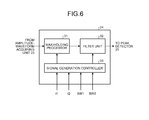
- FIG. 6 is a block diagram illustrating an example of the configuration of a peak-detection signal generator in the first embodiment
- FIG. 7 is a chart for explaining max-holding processing performed in the first embodiment
- FIG. 8 is a chart for explaining the max-holding processing performed in the first embodiment
- FIG. 9 is a chart for explaining the setting of filter parameters in the first embodiment.
- FIG. 10 is a block diagram illustrating an example of the configuration of a peak-detection signal generator according to a second embodiment
- FIG. 11 is a chart for explaining the operation of the peak-detection signal generator in the second embodiment
- FIG. 12 is a chart for explaining the operation of the peak-detection signal generator in the second embodiment
- FIG. 13 is a chart for explaining the operation of the peak-detection signal generator in the second embodiment
- FIG. 14 is a chart for explaining the operation of a radio transmission apparatus according to a third embodiment.
- FIG. 15 is a flowchart for explaining the processing performed by the radio transmission apparatus in the third embodiment.
- FIG. 3 is a block diagram illustrating an example of the configuration of a radio transmission apparatus according to a first embodiment.
- a radio transmission apparatus 100 includes baseband units 11 - 1 and 11 - 2 , delay devices 12 - 1 and 12 - 2 , a peak suppression apparatus 7 , multipliers 14 - 1 and 14 - 2 , an adder 15 , and a digital-to-analog converter (DAC) 16 .
- the radio transmission apparatus 100 further includes an up-converter 17 , a PA 18 , and an antenna 19 .
- the peak suppression apparatus 7 includes multipliers 21 - 1 and 21 - 2 , an adder 22 , an amplitude-waveform acquiring unit 23 , a peak-detection signal generator 24 , a peak detector 25 , and a peak suppressing unit 5 .
- the peak suppressing unit 5 includes a suppression-amount adjusting unit 26 , an impulse response generator 27 , and subtracters 13 - 1 and 13 - 2 .
- the baseband unit 11 - 1 generates a transmission baseband signal 1 by performing baseband processing such as encoding and modulation on transmission data 1 received, and outputs the generated transmission baseband signal 1 to the delay device 12 - 1 and the multiplier 21 - 1 .
- the baseband unit 11 - 2 generates a transmission baseband signal 2 by performing baseband processing such as encoding and modulation on transmission data 2 received, and outputs the generated transmission baseband signal 2 to the delay device 12 - 2 and the multiplier 21 - 2 .
- the transmission data 1 is the data assigned to a carrier frequency f 1 of a multicarrier signal
- the transmission data 2 is the data assigned to a carrier frequency f 2 of the multicarrier signal. That is, the radio transmission apparatus 100 generates the multicarrier signal including the signals of a plurality of carrier frequencies f 1 and f 2 different from each other.
- FIG. 4 is a chart illustrating one example of the multicarrier signal in the first embodiment.
- the multicarrier signal has two carrier frequencies of a carrier f 1 of the frequency f 1 and a carrier f 2 of the frequency f 2 , for example.
- the carrier f 1 and the carrier f 2 are adjacent to each other.
- the carrier f 1 has a carrier bandwidth of BW 1 and the carrier f 2 has a carrier bandwidth of BW 2 .
- a carrier interval between the carrier f 1 and the carrier f 2 is defined by “ ⁇ f” or “ ⁇ fg.”
- the ⁇ f is an interval between the frequency f 1 that is the center frequency in the BW 1 and the frequency f 2 that is the center frequency in the BW 2 .
- the ⁇ fg is an interval between a maximum frequency in the BW 1 , that is, “f 1 +(BW 1 /2)” and a minimum frequency in the BW 2 , that is, “f 2 ⁇ (BW 2 /2).”
- the delay device 12 - 1 delays the transmission baseband signal 1 by a delay amount D, and outputs the transmission baseband signal 1 after delay to the subtracter 13 - 1 .
- the delay device 12 - 2 delays the transmission baseband signal 2 by the delay amount D, and outputs the transmission baseband signal 2 after delay to the subtracter 13 - 2 .
- the total amount of delay in processing at the multipliers 21 - 1 and 21 - 2 , the adder 22 , the amplitude-waveform acquiring unit 23 , the peak-detection signal generator 24 , the peak detector 25 , the suppression-amount adjusting unit 26 , and the impulse response generator 27 is defined as the delay amount D.
- the subtracter 13 - 1 performs peak suppression on the transmission baseband signal 1 by subtracting an impulse response signal received from the impulse response generator 27 from the transmission baseband signal 1 after delay, and outputs the transmission baseband signal 1 after peak suppression to the multiplier 14 - 1 .
- the subtracter 13 - 2 performs peak suppression on the transmission baseband signal 2 by subtracting an impulse response signal received from the impulse response generator 27 from the transmission baseband signal 2 after delay, and outputs the transmission baseband signal 2 after peak suppression to the multiplier 14 - 2 .
- the multiplier 14 - 1 generates a carrier signal 1 of the frequency f 1 by multiplying the transmission baseband signal 1 after peak suppression by the carrier frequency f 1 , and outputs the generated carrier signal 1 to the adder 15 .
- the multiplier 14 - 2 generates a carrier signal 2 of the frequency f 2 by multiplying the transmission baseband signal 2 after peak suppression by the carrier frequency f 2 , and outputs the generated carrier signal 2 to the adder 15 .
- the adder 15 adds and combines the carrier signal 1 and the carrier signal 2 , and outputs the combined signal to the DAC 16 .
- the signal output from the adder 15 is to be a multicarrier signal that includes the carrier signal 1 and the carrier signal 2 .
- the signal output from the adder 15 is to be the multicarrier signal on which the peak suppression has been performed.
- the DAC 16 converts the multicarrier signal from a digital signal into an analog signal and outputs it to the up-converter 17 .
- the up-converter 17 up-converts the analog multicarrier signal and outputs the multicarrier signal after up-conversion to the PA 18 .
- the PA 18 amplifies the electrical power of the multicarrier signal after up-conversion and outputs the multicarrier signal after power amplification to the antenna 19 .
- the antenna 19 wirelessly transmits the multicarrier signal after power amplification.
- the multiplier 21 - 1 generates a carrier signal 1 ′ of the frequency f 1 by multiplying the transmission baseband signal 1 by the carrier frequency f 1 , and outputs the generated carrier signal 1 ′ to the adder 22 .
- the multiplier 21 - 2 generates a carrier signal 2 ′ of the frequency f 2 by multiplying the transmission baseband signal 2 by the carrier frequency f 2 , and outputs the generated carrier signal 2 ′ to the adder 22 .
- the adder 22 adds and combines the carrier signal 1 ′ and the carrier signal 2 ′, and outputs the combined signal to the amplitude-waveform acquiring unit 23 .
- the signal output from the adder 22 is to be a multicarrier signal that includes the carrier signal 1 ′ and the carrier signal 2 ′.
- This multicarrier signal is equivalent to a multicarrier signal on which the peak suppression is not performed, and may be referred to as a replica signal.
- the amplitude-waveform acquiring unit 23 acquires a signal represented by an amplitude waveform of the multicarrier signal (may be referred to as an “amplitude signal” hereinafter), and outputs the acquired amplitude signal to the peak-detection signal generator 24 .
- the peak-detection signal generator 24 receives respective signals representing the carrier frequencies f 1 and f 2 and the carrier bandwidths BW 1 and BW 2 .
- the peak-detection signal generator 24 generates a signal represented by a waveform sequentially connecting a plurality of peak points adjacent to one another in the amplitude signal (may be referred to as a “peak-coupled signal” hereinafter) based on the f 1 , f 2 , BW 1 , and BW 2 .
- the generation of the peak-coupled signal in detail will be described later.
- the peak-detection signal generator 24 outputs the generated peak-coupled signal to the peak detector 25 . That is, the peak-detection signal generator 24 generates the peak-coupled signal as a signal to detect a peak of the multicarrier signal (may be referred to as a “peak detection signal” hereinafter).
- the peak detector 25 detects a peak value and peak timing of the multicarrier signal by using the peak detection signal, and outputs the detected peak value to the suppression-amount adjusting unit 26 and outputs the detected peak timing to the impulse response generator 27 .
- the peak suppressing unit 5 suppresses the peak of the multicarrier signal based on the peak value and peak timing received from the peak detector 25 in the following manner.
- the suppression-amount adjusting unit 26 calculates a value of one-half of the difference between the peak value and a target value as the amount of suppression, and outputs the calculated amount of suppression to the impulse response generator 27 .
- the impulse response generator 27 generates an impulse response signal having a maximum amplitude that is equal to the amount of suppression received from the suppression-amount adjusting unit 26 at the peak timing received from the peak detector 25 , and outputs it to each of the subtracters 13 - 1 and 13 - 2 . That is, the impulse response generator 27 outputs, coinciding with the peak timing, the impulse response signal having the maximum amplitude of the value of one-half of the difference between the peak value and the target value to each of the subtracters 13 - 1 and 13 - 2 as a suppression signal.
- the subtracter 13 - 1 performs the peak suppression on the transmission baseband signal 1 by subtracting the impulse response signal received from the impulse response generator 27 from the transmission baseband signal 1 after delay.
- the subtracter 13 - 2 performs the peak suppression on the transmission baseband signal 2 by subtracting the impulse response signal received from the impulse response generator 27 from the transmission baseband signal 2 after delay.
- FIG. 5 is a chart for explaining the operation of the radio transmission apparatus in the first embodiment.
- the amplitude-waveform acquiring unit 23 acquires an amplitude signal MC 1 from the multicarrier signal received from the adder 22 .
- the peak-detection signal generator 24 generates a peak-coupled signal EN from the amplitude signal MC 1 .
- the peak detector 25 detects, by using the peak-coupled signal EN as a peak detection signal, peaks P 1 and P 2 , which exceed a target value TG, of the peak-coupled signal EN, and peak timing t 1 of the peak P 1 and peak timing t 2 of the peak P 2 .
- the peak detector 25 further detects a peak value A 1 of the peak P 1 and a peak value A 2 of the peak P 2 .
- the suppression-amount adjusting unit 26 calculates “(A 1 ⁇ TG)/2” as the amount of suppression at the peak timing t 1 .
- the suppression-amount adjusting unit 26 further calculates “(A 2 ⁇ TG)/2” as the amount of suppression at the peak timing t 2 .
- the impulse response generator 27 generates an impulse response signal I 1 having “(A 1 ⁇ TG)/2” as a maximum amplitude at the peak timing t 1 and outputs it to the subtracters 13 - 1 and 13 - 2 .
- the impulse response generator 27 further generates an impulse response signal I 2 having “(A 2 ⁇ TG)/2” as a maximum amplitude at the peak timing t 2 and outputs it to the subtracters 13 - 1 and 13 - 2 .
- the impulse response signal I 1 is subtracted from the transmission baseband signal 1 in the subtracter 13 - 1 , and the impulse response signal I 1 is subtracted from the transmission baseband signal 2 in the subtracter 13 - 2 .
- the impulse response signal I 2 is subtracted from the transmission baseband signal 1 in the subtracter 13 - 1 , and the impulse response signal I 2 is subtracted from the transmission baseband signal 2 in the subtracter 13 - 2 .
- each of the peak P 1 and peak P 2 is suppressed down to the target value TG. That is, the signal output from the adder 15 is to be the multicarrier signal in which the peaks are suppressed.
- FIG. 6 is a block diagram illustrating an example of the configuration of the peak-detection signal generator in the first embodiment.
- the peak-detection signal generator 24 includes a max-holding processor 31 , a filter unit 32 , and a signal generation controller 33 .
- the signal generation controller 33 receives signals representing the carrier frequencies f 1 and f 2 and the carrier bandwidths BW 1 and BW 2 .
- the signal generation controller 33 calculates a max-holding parameter and filter parameters from the f 1 , f 2 , BW 1 , and BW 2 , and outputs the max-holding parameter to the max-holding processor 31 and outputs the filter parameters to the filter unit 32 .
- the max-holding processor 31 generates a max-holding signal MH illustrated in FIG. 7 from the amplitude signal MC 1 , and outputs the generated max-holding signal MH to the filter unit 32 . That is, the max-holding processor 31 generates the max-holding signal MH in a manner illustrated in FIG. 8 .
- FIGS. 7 and 8 are charts for explaining the max-holding processing performed in the first embodiment.
- the ⁇ is a sample range in the max-holding, and is the sample range calculated by “n/ ⁇ f” when a sampling rate is defined as “n.”
- the max[ ] is a function to acquire a maximum value.
- the sample range ⁇ is calculated by the signal generation controller 33 based on the carrier frequencies f 1 and f 2 and the sampling rate n, and is set to the max-holding processor 31 as the max-holding parameter.
- the sampling rate n is known by the max-holding processor 31 .
- the carrier interval ⁇ f is calculated by the signal generation controller 33 based on the carrier frequencies f 1 and f 2 .
- the “x(t 0 +2)” that has a maximum amplitude value (“max” in FIG. 8 ) within the range of “(t 0 ⁇ ) ⁇ t ⁇ (t 0 + ⁇ )” is the max-holding value y(t 0 ) of the x(t 0 ).
- the max-holding processor 31 sequentially acquires a maximum amplitude value y(t 0 ) within the sample range ⁇ while shifting the sample range ⁇ in the time axis direction by one sample in sequence. Then, as illustrated in FIG. 8 , the max-holding processor 31 generates the max-holding signal MH that is represented by a waveform sequentially connecting a plurality of acquired maximum amplitude values y(t 0 ).
- the signal generation controller 33 calculates a cutoff frequency and a transition band in a manner illustrated in FIG. 9 as the filter parameters to set to the filter unit 32 .
- FIG. 9 is a chart for explaining the setting of filter parameters in the first embodiment.
- the “transition band” represents a frequency band of up to the frequency fe at which the gain of the filter unit 32 completely falls off from the frequency fs at which the gain of the filter unit 32 begins to fall off.
- the signal generation controller 33 sets “ ⁇ f/2” to the filter unit 32 as the cutoff frequency based on the carrier interval ⁇ f, for example.
- the signal generation controller 33 further sets, based on the carrier bandwidths BW 1 and BW 2 , “4bw” as the frequency fs to the filter unit 32 and “ ⁇ f ⁇ 4bw” as the frequency fe, for example.
- the carrier bandwidths BW 1 and BW 2 have been defined as the same value of “bw.”
- the filter unit 32 operates as a low-pass filter (LPF), in accordance with the filter parameters set by the signal generation controller 33 . That is, when a typical window method is used, the filter unit 32 operates as an LPF having a filter characteristic illustrated in FIG. 9 , in accordance with the cutoff frequency and the transition band, for example. When the Remez method is used, the filter unit 32 operates as an LPF having a filter characteristic illustrated in FIG. 9 , in accordance with the frequency fs and the frequency fe, for example. When the Remez method is used, the signal generation controller 33 sets the frequency fs and the frequency fe to the filter unit 32 as the filter parameters.
- LPF low-pass filter
- the filter unit 32 By the max-holding signal MH illustrated in FIG. 7 being filtered by the filter unit 32 , the peak-coupled signal EN illustrated in FIG. 5 is obtained. That is, the filter unit 32 generates the peak-coupled signal EN by filtering the max-holding signal MH based on the carrier frequencies f 1 and f 2 and the carrier bandwidths BW 1 and BW 2 .
- the peak suppression apparatus 7 includes the amplitude-waveform acquiring unit 23 , the peak-detection signal generator 24 , the peak detector 25 , and the peak suppressing unit 5 .
- the amplitude-waveform acquiring unit 23 acquires the amplitude signal MC 1 that is represented by the amplitude waveform of the multicarrier signal.
- the peak-detection signal generator 24 generates the peak-coupled signal EN that is represented by a waveform sequentially connecting a plurality of peak points adjacent to one another in the amplitude signal MC 1 , as the peak detection signal.
- the peak detector 25 detects a peak value and peak timing of the multicarrier signal by using the peak detection signal.
- the peak suppressing unit 5 suppresses the peak of the multicarrier signal, based on the detected peak value and peak timing.
- the number of peaks in the amplitude waveform can be reduced.
- those peaks can be treated as a single peak of the peak P 1 or the peak P 2 as illustrated in FIG. 5 . Consequently, even when a plurality of peaks exceeding the target value are present in the multicarrier signal within a short time range, a single optimal peak timing within the short time range can be detected.
- a single optimal timing of adding an impulse response signal out of a plurality of peak timings that correspond to the peaks exceeding the target value can be determined in response to various patterns of the multicarrier signal. Consequently, in accordance with the first embodiment, the processing to determine the optimal timing of adding an impulse response signal is made simple, and thereby the circuit scale of the radio transmission apparatus can be reduced.
- the peak-detection signal generator 24 sequentially acquires a maximum amplitude value y(t 0 ) within a given sample range ⁇ while shifting the given sample range ⁇ in the amplitude signal MC 1 in sequence.
- the peak-detection signal generator 24 further generates the max-holding signal MH that is represented by the waveform sequentially connecting a plurality of acquired maximum amplitude values y(t 0 ).
- the peak-detection signal generator 24 then generates the peak-coupled signal EN by filtering the max-holding signal MH based on the carrier frequencies f 1 and f 2 and the carrier bandwidths BW 1 and BW 2 .
- the peak-coupled signal EN as the peak detection signal can be generated by simple processing of the max-holding processing and the filtering processing.
- the configuration of the peak-detection signal generator 24 differs from that in the first embodiment.
- FIG. 10 is a block diagram illustrating an example of the configuration of the peak-detection signal generator according to the second embodiment.
- filter units 41 - 1 to 41 - n when the filter units 41 - 1 to 41 - n are not distinguished, they may be collectively referred to as filter units 41 .
- the amplitude cutting units 42 - 1 to 42 - m are not distinguished, they may be collectively referred to as amplitude cutting units 42 .
- the filter units 41 and the amplitude cutting units 42 are coupled alternately.
- the filter units 41 each operate as an LPF in the same manner as that in the first embodiment, and perform the filtering processing on the signal input to the filter units 41 .
- the amplitude cutting units 42 each perform amplitude cutting processing in which a part of the amplitude of the signal input to the amplitude cutting units 42 is cut down based on the signal after the filtering processing performed by the filter units 41 .
- FIGS. 11 to 13 are charts for explaining the operation of the peak-detection signal generator in the second embodiment.
- the amplitude signal MC 1 is input from the amplitude-waveform acquiring unit 23 .
- the filter unit 41 - 1 performs the filtering processing on the amplitude signal MC 1 as illustrated in FIG. 11 , and outputs a signal LP 1 after filtering processing to the amplitude cutting unit 42 - 1 .
- the waveform of the signal LP 1 after filtering processing is to be a waveform that passes through the average of the amplitude variation of the amplitude signal MC 1 .
- the amplitude cutting unit 42 - 1 cuts down the amplitude that is equal to or lower than the amplitude of the signal LP 1 in the amplitude signal MC 1 , and outputs a signal OP 1 after cutting as illustrated in FIG. 12 to the filter unit 41 - 2 and the amplitude cutting unit 42 - 2 .
- the bottom envelope of the signal OP 1 is clipped at the amplitude level of the signal LP 1 .
- the filter unit 41 - 2 performs the filtering processing on the signal OP 1 as illustrated in FIG. 12 , and outputs a signal LP 2 after filtering processing to the amplitude cutting unit 42 - 2 .
- the waveform of the signal LP 2 after filtering processing is to be a waveform that passes through the average of the amplitude variation of the signal OP 1 .
- the amplitude cutting unit 42 - 2 cuts down the amplitude that is equal to or lower than the amplitude of the signal LP 2 in the signal OP 1 , and outputs a signal OP 2 after cutting to the filter unit 41 in a downstream stage and the amplitude cutting unit 42 in a downstream stage.
- the bottom envelope of the signal OP 2 is clipped at the amplitude level of the signal LP 2 .
- the peak-detection signal generator 24 illustrated in FIG. 10 repeatedly performs, on the amplitude signal MC 1 a number of times, the filtering processing based on the carrier frequencies f 1 and f 2 and the carrier bandwidths BW 1 and BW 2 , and the amplitude cutting processing in which a part of the amplitude is cut down based on the signal after filter processing.
- the waveforms of the signals LP 1 to LP 5 after filtering processing gradually approach the waveform of the peak-coupled signal EN and a signal LPn output from the filter unit 41 - n at the final stage is equivalent to the peak-coupled signal EN. That is, by repeatedly performing the filtering processing and the amplitude cutting processing on the amplitude signal MC 1 a number of times, the peak-coupled signal EN as a peak detection signal can be obtained.
- the peak-detection signal generator 24 generates the peak-coupled signal EN by repeatedly performing the filtering processing and the amplitude cutting processing on the amplitude signal MC 1 a number of times.
- the peak-coupled signal EN as the peak detection signal can be generated by simple processing of the filtering processing and the amplitude cutting processing.
- a third embodiment it differs from the first embodiment in that the signal used as a peak detection signal is switched, based on a carrier interval, between a peak-coupled signal and an amplitude signal.
- the carrier interval widens in the multicarrier signal, as illustrated in FIG. 2 , the variation in amplitude of the multicarrier signal in the time axis direction becomes sharp. Hence, when the carrier interval widens, there are cases in which a plurality of peaks exceeding the target value are detected within a short time range.
- the situation of “the carrier interval being wide” is a situation in which “N ⁇ bw ⁇ f” holds true, for example, and the situation of “the carrier interval being narrow” is a situation in which “N ⁇ bw> ⁇ f” holds true, for example.
- the “N” here is an integer, and is any of 4, 7, and 8, for example.
- the “N” is set to a value in which, out of the frequency components that can be cut out from the frequency spectrum of the multicarrier signal, the width of the frequency component that appears at zero Hertz is divided by bw (rounded down to the nearest decimal), for example.
- the signal generation controller 33 calculates the carrier interval ⁇ f based on the carrier frequencies f 1 and f 2 . The signal generation controller 33 then determines whether the ⁇ f satisfies the condition of “N ⁇ bw ⁇ f” with “N ⁇ bw” as a threshold.
- the carrier bandwidths BW 1 and BW 2 have been defined as the same value of “bw.”
- the signal generation controller 33 sets, in the same manner as those in the first embodiment, the max-holding parameter to the max-holding processor 31 and sets the filter parameters to the filter unit 32 . Consequently, when the carrier interval is wide, the peak suppression is performed by using, as the peak detection signal, the peak-coupled signal EN generated in the same manner as that in the first embodiment.
- the signal generation controller 33 further sets a cutoff frequency of ⁇ (infinity) to the filter unit 32 as the filter parameters.
- the filter unit 32 operates as an LPF with the cutoff frequency of ⁇ , and thus in the filter unit 32 , the filtering processing is not performed and the amplitude signal received from the max-holding processor 31 is output to the peak detector 25 as is. That is, when the carrier interval is narrow, the amplitude signal input to the peak-detection signal generator 24 ignores the max-holding processing and the filtering processing, and is output from the peak-detection signal generator 24 as is. Thus, when the carrier interval is narrow, the amplitude signal acquired by the amplitude-waveform acquiring unit 23 is to be the peak detection signal as is.
- FIG. 14 is a chart for explaining the operation of the radio transmission apparatus in the third embodiment.
- FIG. 14 illustrates an example of the operation when the carrier interval is narrow.
- the example of the operation when the carrier interval is wide is the same as that in the first embodiment, and thus its explanation is omitted.
- the amplitude-waveform acquiring unit 23 acquires an amplitude signal MC 2 as illustrated in FIG. 14 from the multicarrier signal received from the adder 22 , and outputs the acquired amplitude signal MC 2 to the peak-detection signal generator 24 . Because the carrier interval is narrow, in the amplitude signal MC 2 , as compared with the amplitude signal MC 1 in FIG. 5 , the amplitude variation of the multicarrier signal in the time axis direction is gradual.
- the peak-detection signal generator 24 outputs the amplitude signal MC 2 to the peak detector 25 as is.
- the peak detector 25 detects, by using the amplitude signal MC 2 as the peak detection signal, peaks P 3 and P 4 , which exceed the target value TG, of the amplitude signal MC 2 , and peak timing t 3 of the peak P 3 and peak timing t 4 of the peak P 4 .
- the peak detector 25 further detects a peak value A 3 of the peak P 3 and a peak value A 4 of the peak P 4 .
- the suppression-amount adjusting unit 26 calculates “(A 3 ⁇ TG)/2” as the amount of suppression at the peak timing t 3 .
- the suppression-amount adjusting unit 26 further calculates “(A 4 ⁇ TG)/2” as the amount of suppression at the peak timing t 4 .
- the impulse response generator 27 generates an impulse response signal I 3 having “(A 3 ⁇ TG)/2” as a maximum amplitude at the peak timing t 3 and outputs it to the subtracters 13 - 1 and 13 - 2 .
- the impulse response generator 27 further generates an impulse response signal 14 having “(A 4 ⁇ TG)/2” as a maximum amplitude at the peak timing t 4 and outputs it to the subtracters 13 - 1 and 13 - 2 .
- the impulse response signal I 3 is subtracted from the transmission baseband signal 1 in the subtracter 13 - 1 , and the impulse response signal I 3 is subtracted from the transmission baseband signal 2 in the subtracter 13 - 2 .
- the impulse response signal 14 is subtracted from the transmission baseband signal 1 in the subtracter 13 - 1 , and the impulse response signal 14 is subtracted from the transmission baseband signal 2 in the subtracter 13 - 2 .
- each of the peak P 3 and peak P 4 is suppressed down to the target value TG. That is, the signal output from the adder 15 is to be the multicarrier signal in which the peaks are suppressed.
- FIG. 15 is a flowchart for explaining the processing performed by the radio transmission apparatus in the third embodiment.
- the flowchart illustrated in FIG. 15 is started at regular time intervals.
- the signal generation controller 33 in the peak-detection signal generator 24 determines whether “N ⁇ bw ⁇ f” holds true, that is, whether the carrier interval ⁇ f is equal to or greater than N times the carrier bandwidth bw (Step S 51 ).
- the peak-detection signal generator 24 outputs a peak-coupled signal generated in the same manner as that in the first embodiment to the peak detector 25 as the peak detection signal (Step S 52 ).
- the peak-detection signal generator 24 outputs the amplitude signal received from the amplitude-waveform acquiring unit 23 as is to the peak detector 25 as the peak detection signal (Step S 53 ).
- the peak detector 25 when the carrier interval is equal to or greater than a given integer number of times the carrier bandwidth, the peak detector 25 detects a peak value and peak timing by using the peak-coupled signal as the peak detection signal. In contrast, when the carrier interval is below the given integer number of times the carrier bandwidth, the peak detector 25 detects a peak value and peak timing by using the amplitude signal as the peak detection signal.
- the peak detection signal when the carrier interval is narrow, the peak detection signal can be generated omitting the max-holding processing and the filtering processing, and thereby the processing of generating the peak detection signal when the carrier interval is narrow can be simplified.
- a fourth embodiment it is the same as the third embodiment in that the signal to be used as the peak detection signal is switched between the peak-coupled signal and the amplitude signal based on the carrier interval. However, in the fourth embodiment, it differs from the third embodiment in that the peak-detection signal generator 24 employs the configuration in the second embodiment ( FIG. 10 ).
- the signal generation controller 33 calculates the carrier interval ⁇ f based on the carrier frequencies f 1 and f 2 . The signal generation controller 33 then determines whether the ⁇ f satisfies the condition of “N ⁇ bw ⁇ f” with “N ⁇ bw” as a threshold.
- the carrier bandwidths BW 1 and BW 2 have been defined as the same value of “bw.”
- the signal generation controller 33 sets, in the same manner as that in the second embodiment, the filter parameters to the filter units 41 . Consequently, when the carrier interval is wide, the peak suppression is performed by using the peak-coupled signal EN generated in the same manner as that in the second embodiment, as the peak detection signal.
- the signal generation controller 33 sets a cutoff frequency of ⁇ (infinity) to the filter units 41 as the filter parameters. Consequently, the filter units 41 operate as an LPF with the cutoff frequency of ⁇ , and thereby the filtering processing is not performed in the filter units 41 and the amplitude signal received from a functional unit in the upstream stage is output as is to a functional unit in the downstream stage.
- the amplitude cutting units 42 because the signal to be the target of amplitude cutting processing and the signal to be the reference of the amplitude cutting processing are the same, the amplitude cutting processing is not to be performed.
- the amplitude signal input to the peak-detection signal generator 24 ignores the filtering processing and the amplitude cutting processing, and is output as is from the peak-detection signal generator 24 .
- the amplitude signal acquired by the amplitude-waveform acquiring unit 23 is to be the peak detection signal as is.
- the peak detector 25 detects a peak value and peak timing by using the peak-coupled signal as the peak detection signal. In contrast, when the carrier interval is below the given integer number of times the carrier bandwidth, the peak detector 25 detects a peak value and peak timing by using the amplitude signal as the peak detection signal.
- the peak detection signal can be generated omitting the filtering processing and the amplitude cutting processing, and thereby the processing of generating the peak detection signal when the carrier interval is narrow can be simplified.
- the ⁇ f has been used as the carrier interval.
- the ⁇ fg may be used as the carrier interval.
- the carrier interval ⁇ fg is calculated based on the carrier frequencies f 1 and f 2 and the carrier bandwidths BW 1 and BW 2 .
- the cutoff frequency, the frequencies fs and fe indicative of a transition band, and the sample range ⁇ are calculated in the following manner.
- whether the carrier interval is wide or narrow is determined in the following manner. That is, in place of determining whether the carrier interval is wide or narrow by determining whether the condition of “8bw ⁇ f” is satisfied, it is preferable that whether the carrier interval is wide or narrow be determined by determining whether the condition of “7bw ⁇ fg” is satisfied.
- the peak suppression apparatus 7 is implemented, as hardware, with a field programmable gate array (FPGA), a large-scale integrated circuit (LSI), or a processor, for example.
- the processor includes a central processing unit (CPU) and a digital signal processor (DSP).
- the peak suppression apparatus 7 may further include a memory.
- the memory stores therein the sampling rate n, for example.
- the circuit scale of the radio transmission apparatus that performs the peak suppression of a multicarrier signal can be reduced.
Abstract
Description
y(t 0)=max[x(t 0−α),x(t 0−α+1), . . . x(t 0−1),x(t 0),x(t 0+1), . . . x(t 0+α−1),x(t 0+α)] (1)
Cutoff frequency=(Δfg+bw)/2
Frequency fs=4bw
Frequency fe=Δfg−3bw
Sample range α=Sampling rate/(Δfg+bw)
Claims (3)
Applications Claiming Priority (2)
| Application Number | Priority Date | Filing Date | Title |
|---|---|---|---|
| JP2014-126703 | 2014-06-19 | ||
| JP2014126703A JP2016005259A (en) | 2014-06-19 | 2014-06-19 | Peak suppression device |
Publications (2)
| Publication Number | Publication Date |
|---|---|
| US20150372850A1 US20150372850A1 (en) | 2015-12-24 |
| US9515861B2 true US9515861B2 (en) | 2016-12-06 |
Family
ID=54870647
Family Applications (1)
| Application Number | Title | Priority Date | Filing Date |
|---|---|---|---|
| US14/697,897 Expired - Fee Related US9515861B2 (en) | 2014-06-19 | 2015-04-28 | Peak suppression apparatus |
Country Status (2)
| Country | Link |
|---|---|
| US (1) | US9515861B2 (en) |
| JP (1) | JP2016005259A (en) |
Citations (5)
| Publication number | Priority date | Publication date | Assignee | Title |
|---|---|---|---|---|
| US5444697A (en) * | 1993-08-11 | 1995-08-22 | The University Of British Columbia | Method and apparatus for frame synchronization in mobile OFDM data communication |
| JP2002305489A (en) | 2001-04-05 | 2002-10-18 | Fujitsu Ltd | Code multiplex signal transmission apparatus |
| US20060133524A1 (en) * | 2004-12-20 | 2006-06-22 | Fujitsu Limited | Multicarrier signal transmission apparatus, multicarrier signal receiving apparatus, multicarrier signal transmission method, multicarrier signal receiving method, and communication system |
| US20090191923A1 (en) * | 2008-01-25 | 2009-07-30 | Fujitsu Limited | Power amplifying apparatus with bandwidth limitation processing on variable power supply |
| JP2014027343A (en) | 2012-07-24 | 2014-02-06 | Japan Radio Co Ltd | Peak suppression circuit |
-
2014
- 2014-06-19 JP JP2014126703A patent/JP2016005259A/en not_active Withdrawn
-
2015
- 2015-04-28 US US14/697,897 patent/US9515861B2/en not_active Expired - Fee Related
Patent Citations (5)
| Publication number | Priority date | Publication date | Assignee | Title |
|---|---|---|---|---|
| US5444697A (en) * | 1993-08-11 | 1995-08-22 | The University Of British Columbia | Method and apparatus for frame synchronization in mobile OFDM data communication |
| JP2002305489A (en) | 2001-04-05 | 2002-10-18 | Fujitsu Ltd | Code multiplex signal transmission apparatus |
| US20060133524A1 (en) * | 2004-12-20 | 2006-06-22 | Fujitsu Limited | Multicarrier signal transmission apparatus, multicarrier signal receiving apparatus, multicarrier signal transmission method, multicarrier signal receiving method, and communication system |
| US20090191923A1 (en) * | 2008-01-25 | 2009-07-30 | Fujitsu Limited | Power amplifying apparatus with bandwidth limitation processing on variable power supply |
| JP2014027343A (en) | 2012-07-24 | 2014-02-06 | Japan Radio Co Ltd | Peak suppression circuit |
Also Published As
| Publication number | Publication date |
|---|---|
| JP2016005259A (en) | 2016-01-12 |
| US20150372850A1 (en) | 2015-12-24 |
Similar Documents
| Publication | Publication Date | Title |
|---|---|---|
| CN105743834B (en) | Reducing peak-to-average power ratio of OFDM signals | |
| US10326630B2 (en) | Extracting sub-bands from signals in a frequency domain | |
| JP2016538761A (en) | Reduced bandwidth of signal in envelope path for envelope tracking system | |
| WO2016106719A1 (en) | Signal clipping processing method and apparatus | |
| KR20110087115A (en) | Method and apparatus for reducing peak to average power ratio by using peak windowing | |
| US9197475B2 (en) | Base band processor with peak suppression function, transmitter with the same and method of transmitting signal | |
| JP5011317B2 (en) | Reduce signal peak-to-average power ratio | |
| KR101664797B1 (en) | Method for PAPR Reduction of OFDM Signals and OFDM Transmitter using the same | |
| KR101613731B1 (en) | Apparatus and method for extracting reference cancellation pulse in multi-carrier system and peak cancellation crest factor reduction system for the same | |
| US8654887B2 (en) | Methods and systems for peak-to-average power reduction without reducing data rate | |
| US9515861B2 (en) | Peak suppression apparatus | |
| JP4288458B2 (en) | Amplitude limiting circuit and CDMA communication apparatus | |
| JP4958775B2 (en) | Multicarrier transmission apparatus and multicarrier transmission method | |
| KR20160027302A (en) | RF transmitter supporting carrier aggregation and envelope tracking | |
| JP2008258703A (en) | Transmitter | |
| CN104980385B (en) | A kind of signal despicking method and equipment | |
| US10904060B2 (en) | Peak suppression circuit, peak suppression method, and transmitter | |
| US20160261445A1 (en) | Peak suppression device and peak suppression method | |
| JP5175751B2 (en) | Peak factor reduction device and base station | |
| US9479374B1 (en) | Digital front-end channelization device | |
| KR20110001464A (en) | Method and apparatus for signal processing for combining multi signals | |
| US8130866B2 (en) | Peak suppressing apparatus, peak suppressing method, and wireless communication device | |
| CN109937532B (en) | Crest factor reduction in power amplifier circuits | |
| US9813273B2 (en) | Peak suppression device | |
| JP2018148510A (en) | Communication apparatus, pulse width modulator, and pulse width modulation method |
Legal Events
| Date | Code | Title | Description |
|---|---|---|---|
| AS | Assignment |
Owner name: FUJITSU LIMITED, JAPAN Free format text: ASSIGNMENT OF ASSIGNORS INTEREST;ASSIGNORS:OTA, TOMOYA;ISHIKAWA, HIROYOSHI;NAGATANI, KAZUO;SIGNING DATES FROM 20150406 TO 20150408;REEL/FRAME:035724/0602 |
|
| STCF | Information on status: patent grant |
Free format text: PATENTED CASE |
|
| FEPP | Fee payment procedure |
Free format text: MAINTENANCE FEE REMINDER MAILED (ORIGINAL EVENT CODE: REM.); ENTITY STATUS OF PATENT OWNER: LARGE ENTITY |
|
| LAPS | Lapse for failure to pay maintenance fees |
Free format text: PATENT EXPIRED FOR FAILURE TO PAY MAINTENANCE FEES (ORIGINAL EVENT CODE: EXP.); ENTITY STATUS OF PATENT OWNER: LARGE ENTITY |
|
| STCH | Information on status: patent discontinuation |
Free format text: PATENT EXPIRED DUE TO NONPAYMENT OF MAINTENANCE FEES UNDER 37 CFR 1.362 |
|
| FP | Lapsed due to failure to pay maintenance fee |
Effective date: 20201206 |