US9521378B1 - Remote display of satellite receiver information - Google Patents
Remote display of satellite receiver information Download PDFInfo
- Publication number
- US9521378B1 US9521378B1 US14/586,777 US201414586777A US9521378B1 US 9521378 B1 US9521378 B1 US 9521378B1 US 201414586777 A US201414586777 A US 201414586777A US 9521378 B1 US9521378 B1 US 9521378B1
- Authority
- US
- United States
- Prior art keywords
- computing device
- satellite receiver
- satellite
- request
- receiver data
- Prior art date
- Legal status (The legal status is an assumption and is not a legal conclusion. Google has not performed a legal analysis and makes no representation as to the accuracy of the status listed.)
- Active
Links
- 238000000034 method Methods 0.000 claims description 44
- 238000004891 communication Methods 0.000 claims description 39
- 230000004044 response Effects 0.000 claims description 13
- 230000006870 function Effects 0.000 claims description 9
- 238000005259 measurement Methods 0.000 description 25
- 230000008569 process Effects 0.000 description 13
- 238000012360 testing method Methods 0.000 description 12
- 238000009434 installation Methods 0.000 description 11
- 238000010586 diagram Methods 0.000 description 8
- 230000001413 cellular effect Effects 0.000 description 6
- 238000013500 data storage Methods 0.000 description 6
- 238000012795 verification Methods 0.000 description 5
- 230000008859 change Effects 0.000 description 4
- 239000000463 material Substances 0.000 description 4
- 230000003287 optical effect Effects 0.000 description 4
- 238000004364 calculation method Methods 0.000 description 3
- 230000009471 action Effects 0.000 description 2
- 238000004873 anchoring Methods 0.000 description 2
- 230000005540 biological transmission Effects 0.000 description 2
- 238000005516 engineering process Methods 0.000 description 2
- 230000007246 mechanism Effects 0.000 description 2
- 238000012545 processing Methods 0.000 description 2
- 230000005236 sound signal Effects 0.000 description 2
- 238000013024 troubleshooting Methods 0.000 description 2
- 230000000007 visual effect Effects 0.000 description 2
- 238000013459 approach Methods 0.000 description 1
- 230000007774 longterm Effects 0.000 description 1
- 238000004519 manufacturing process Methods 0.000 description 1
- 238000012544 monitoring process Methods 0.000 description 1
- 230000006855 networking Effects 0.000 description 1
- 230000002085 persistent effect Effects 0.000 description 1
- 238000009428 plumbing Methods 0.000 description 1
- 239000007787 solid Substances 0.000 description 1
- 238000012546 transfer Methods 0.000 description 1
- 230000007723 transport mechanism Effects 0.000 description 1
Images


Classifications
-
- H—ELECTRICITY
- H04—ELECTRIC COMMUNICATION TECHNIQUE
- H04N—PICTORIAL COMMUNICATION, e.g. TELEVISION
- H04N7/00—Television systems
- H04N7/20—Adaptations for transmission via a GHz frequency band, e.g. via satellite
-
- H—ELECTRICITY
- H01—ELECTRIC ELEMENTS
- H01Q—ANTENNAS, i.e. RADIO AERIALS
- H01Q1/00—Details of, or arrangements associated with, antennas
- H01Q1/12—Supports; Mounting means
- H01Q1/125—Means for positioning
-
- H—ELECTRICITY
- H01—ELECTRIC ELEMENTS
- H01Q—ANTENNAS, i.e. RADIO AERIALS
- H01Q1/00—Details of, or arrangements associated with, antennas
- H01Q1/12—Supports; Mounting means
- H01Q1/125—Means for positioning
- H01Q1/1257—Means for positioning using the received signal strength
-
- H—ELECTRICITY
- H04—ELECTRIC COMMUNICATION TECHNIQUE
- H04H—BROADCAST COMMUNICATION
- H04H40/00—Arrangements specially adapted for receiving broadcast information
- H04H40/18—Arrangements characterised by circuits or components specially adapted for receiving
- H04H40/27—Arrangements characterised by circuits or components specially adapted for receiving specially adapted for broadcast systems covered by groups H04H20/53 - H04H20/95
- H04H40/90—Arrangements characterised by circuits or components specially adapted for receiving specially adapted for broadcast systems covered by groups H04H20/53 - H04H20/95 specially adapted for satellite broadcast receiving
-
- H—ELECTRICITY
- H04—ELECTRIC COMMUNICATION TECHNIQUE
- H04N—PICTORIAL COMMUNICATION, e.g. TELEVISION
- H04N21/00—Selective content distribution, e.g. interactive television or video on demand [VOD]
- H04N21/40—Client devices specifically adapted for the reception of or interaction with content, e.g. set-top-box [STB]; Operations thereof
- H04N21/43—Processing of content or additional data, e.g. demultiplexing additional data from a digital video stream; Elementary client operations, e.g. monitoring of home network or synchronising decoder's clock; Client middleware
- H04N21/435—Processing of additional data, e.g. decrypting of additional data, reconstructing software from modules extracted from the transport stream
-
- H—ELECTRICITY
- H04—ELECTRIC COMMUNICATION TECHNIQUE
- H04N—PICTORIAL COMMUNICATION, e.g. TELEVISION
- H04N21/00—Selective content distribution, e.g. interactive television or video on demand [VOD]
- H04N21/40—Client devices specifically adapted for the reception of or interaction with content, e.g. set-top-box [STB]; Operations thereof
- H04N21/47—End-user applications
- H04N21/485—End-user interface for client configuration
-
- H—ELECTRICITY
- H04—ELECTRIC COMMUNICATION TECHNIQUE
- H04N—PICTORIAL COMMUNICATION, e.g. TELEVISION
- H04N21/00—Selective content distribution, e.g. interactive television or video on demand [VOD]
- H04N21/60—Network structure or processes for video distribution between server and client or between remote clients; Control signalling between clients, server and network components; Transmission of management data between server and client, e.g. sending from server to client commands for recording incoming content stream; Communication details between server and client
- H04N21/61—Network physical structure; Signal processing
- H04N21/6106—Network physical structure; Signal processing specially adapted to the downstream path of the transmission network
- H04N21/6143—Network physical structure; Signal processing specially adapted to the downstream path of the transmission network involving transmission via a satellite
Definitions
- Satellite broadcasting of information may involve substantial infrastructure to deliver signals to terrestrial satellite receivers.
- a plurality of ground-based microwave transmitters may transmit information to a plurality of satellites along a communication uplink.
- the plurality of satellites may be in geostationary orbit in a corresponding plurality of orbital slots.
- Each satellite may retransmit the information toward ground locations as one or more satellite transponder signals via a radio frequency communication downlink.
- a satellite antenna, or outdoor unit (ODU), usually mounted to a building housing the satellite receiver, may receive the one or more satellite transponder signals.
- ODU outdoor unit
- Such ODUs are commonly used at both residential and commercial venues to receive satellite television service.
- the ODU To receive the satellite transponder signals at their various orbital slots, the ODU must be correctly aligned along the correct azimuth, elevation, and tilt angles, depending on the geographic location of the ODU.
- Current methods for aligning ODUs tend to be complicated, and are generally only carried out by specialized technicians using a specialized signal meter that contains satellite downlink information on which the alignment process may be based.
- the signal meter is typically connected directly to the ODU via a coaxial connection.
- the technician then proceeds through the course alignment process, followed by the fine alignment process, which may require a multitask procedure of monitoring the signal meter while simultaneously rotating the ODU and recording the rotations, as well as performing manual calculations.
- Satellite downlinks change over time due to capacity increases, modulation standards, geographical service areas, and installation verification thresholds. This in turn may affect the desired alignment for a given ODU. Because of this, a standalone signal meter, which might not be network connected, requires manual updating to avoid improper ODU alignment.
- the present disclosure generally relates to the generation and remote display of information from a satellite receiver, and in particular, the generation and display of information to facilitate the installation and alignment of a satellite antenna, or outdoor unit (ODU).
- ODU outdoor unit
- example embodiments may provide a graphical user-interface (GUI) that assists a home user in the process of installing and aligning an ODU at their home.
- GUI graphical user-interface
- a first computing device may include (i) a communications interface; (ii) a processor; (iii) a non-transitory computer readable medium; and (iv) program instructions stored on the non-transitory computer readable medium that, when executed by the processor, cause the first computing device to perform functions including (a) receiving, by the first computing device from a second computing device, a request for satellite receiver data, where the request for the satellite receiver data comprises a request for an instruction for aligning a satellite antenna, and where the first computing device is communicatively connected to the satellite antenna; (b) receiving, by the first computing device, the satellite receiver data; (c) based on the received satellite receiver data, determining an instruction for aligning the satellite antenna; and (d) transmitting, by the first computing device to the second computing device, the satellite receiver data, where the satellite receiver data comprises the instruction for aligning the satellite antenna.
- FIG. 1 is a simplified block diagram that illustrates a communication system, according to an example embodiment.
- FIG. 3 is a functional block diagram that illustrates a server used in a communication system, according to an example embodiment.
- FIG. 4 is a functional block diagram that illustrates another computing device used in a communication system, according to an example embodiment.
- FIG. 5 is a flow chart according to an example embodiment.
- FIG. 6A is a screenshot of a graphical display, according to an example embodiment.
- FIG. 6B is another screenshot of the graphical display, according to an example embodiment.
- FIG. 6C is yet another screenshot of the graphical display, according to an example embodiment.
- FIG. 7 is a flow chart according to an example embodiment.
- Embodiments are provided herein to facilitate the remote display of satellite receiver information, which may be used to facilitate the installation and alignment of a satellite antenna, or outdoor unit (ODU). Further, an example embodiment may allow an end user to perform a “do it yourself” alignment of an ODU using existing computing devices. This in turn may reduce the need for specialized equipment and personnel, and thus may reduce the overall cost of ODU installations. While the examples herein are generally focused on the installation and alignment of an ODU, the displayed satellite information may be used for other purposes as well.
- satellite receiver information may be used to facilitate the installation and alignment of a satellite antenna, or outdoor unit (ODU).
- ODU outdoor unit
- an example embodiment may allow an end user to perform a “do it yourself” alignment of an ODU using existing computing devices. This in turn may reduce the need for specialized equipment and personnel, and thus may reduce the overall cost of ODU installations. While the examples herein are generally focused on the installation and alignment of an ODU, the displayed satellite information may be used for other purposes as well.
- a typical set-top box may include the necessary hardware to obtain signal measurements from an ODU.
- aligning the ODU based on information from the STB is generally not practical, as STBs and any connected displays (e.g., a TV) are typically installed in living rooms, while ODUs are installed outdoors, typically on rooftops. Consequently, satellite receiver data from the STB may be provided to a remote computing device, which may display the information on a graphical display, for use in aligning the ODU.
- the remote computing device may be a computing device that an end user may already possess, such as a smartphone, a tablet computer, a laptop computer, wearable computing device, etc.
- the computing device may be connected to and communicate with the STB via a local network, such as a home WiFi network.
- the computing device may transmit requests for satellite receiver data, including requests for instructions for aligning the ODU.
- FIG. 1 is a simplified block diagram that illustrates a communication system 100 in which embodiments of the disclosed methods and entities can be implemented.
- the communication system 100 may include a satellite 102 , a head end 104 , one or more set-top boxes (STBs) 106 , 108 , one or more user devices 110 , one or more networks 112 , and one or more servers 114 , such as a message handler server, a billing system server, a customer service center server, a call placement system server, and an ODU alignment server, among other examples.
- Other devices may also be included in the communication system 100 .
- STBs set-top boxes
- Other devices may also be included in the communication system 100 .
- multiple satellites, head ends, servers, and other components might be included in the communication system 100 .
- multiple components are illustrated separately, it should be understood that one or more of the components may be implemented as distributed components.
- Satellite 102 may include one or more antennas 120 , 122 configured to send and receive digital or analog signals to one or more devices in the communication system 100 .
- satellite 102 may include a first antenna 120 configured to receive data via an uplink signal from a device, such as head end 104 .
- Satellite 102 may also include a second antenna 122 that may transmit data via a downlink signal to a receiving device.
- the receiving device may be a mobile device or a stationary device.
- Set-top boxes 106 , 108 or user device 110 may be a mobile device or a stationary device.
- a single antenna may be used to receive data via an uplink signal and transmit data via a downlink signal. Other examples are also possible.
- Set-top boxes 106 , 108 are examples of receiving devices configured to receive data from satellite 102 or network 112 .
- set-top box 106 may include or be connected to an antenna, or outdoor unit (ODU), 128 for receiving downlink signals from antenna 122 .
- Set-top box 106 may also include one or more components structured and arranged to receive signals from network 112 .
- the type, content, and number of signals received by set-top box 106 may vary.
- the signals may be media signals that may include video or audio signals. Data sent via the media signals may include content, program data, images, requests, or the like.
- set-top boxes 106 , 108 may each comprise a DVR or other device for recording and storing digital content or other such data. Other examples are also possible.
- set-top boxes 106 , 108 may be interconnected with one or more devices in the communication system 100 via a local network (not illustrated).
- the local network which may be a wired network or wireless network, may be used to interconnect set-top boxes 106 , 108 within a household, multi-dwelling unit, or commercial building.
- the local network may also allow for multi-room viewing of content stored on a first set-top box (such as set-top box 106 ) and communicated to a second set-top box (such as set-top box 108 ) through the local network.
- the stored content can comprise content a set-top box 106 receives from antenna 128 .
- user device 110 may be linked communicatively, via a local network or other type of wired or wireless network, with one or more set-top boxes owned and maintained by a user, such as set-top box 108 as shown in FIG. 1 .
- set-top box 108 owned and maintained by a user
- Other examples are possible as well.
- FIG. 2 is a functional block diagram that illustrates a computing device 200 used in a communication system in accordance with embodiments described herein.
- Computing device 200 may take a variety of forms.
- computing device 200 may comprise or be arranged as a set-top box (such as set-top boxes 106 , 108 of FIG. 1 ), and may further comprise a DVR or other digital content recording device.
- the set-top box may be used for television or other media.
- computing device 200 may comprise or be arranged as a landline or cellular telephone, smartphone, personal computer, laptop computer, tablet computer, personal digital assistant (PDA), portable media player, a wearable computing device, or other computing device now known or later developed.
- PDA personal digital assistant
- Antenna 202 may be one of a number of different types of antennas that may include one or more low noise blocks downconverters (LNB) associated therewith.
- antenna 202 may be a single antenna for receiving signals from a satellite (such as satellite 102 of FIG. 1 ), network (such as network 112 of FIG. 1 ), or terrestrial source.
- antenna 202 may include multiple antennas for different orbital slots.
- signals and other items described as being received by antenna 202 can be received by network interface 244 by way of a coaxial cable or other communication link. In that regard, one or more signals or items received at network interface 244 can be forwarded to tuner 204 .
- Tuner 204 may receive a signal from antenna 202 .
- the signal may be a media signal that may include video or audio signals.
- the signal may also include a television signal.
- the content of the signal may vary based on the type of signal. For example, the content may include television programming content, program guide data or other types of data.
- Tuner 204 may then communicate the signal to demodulator 206 .
- Demodulator 206 may receive the signal and demodulate the signal to form a demodulated signal. Decoder 208 may decode the demodulated signal to form a decoded signal or decoded data. The decoded signal may then be sent to processor 210 or output driver 250 . However, other examples are also possible.
- Processor 210 may be any type of processor, such as a microprocessor, a microcontroller, a digital signal processor (DSP), multicore processor, etc. Processor 210 may be used to coordinate or control tuner 204 , demodulator 206 , decoder 208 , and any other components of computing device 200 that may or may not be illustrated in FIG. 2 . In some implementations, processor 210 may include an internal memory controller (not illustrated). Yet other implementations may include a separate memory controller that can be used with processor 210 .
- DSP digital signal processor
- a memory bus 228 can be used for communicating between the processor 210 and memory 212 .
- Memory 212 may be any suitable type of memory.
- memory 212 may include a non-transitory computer-readable medium, for example, such as computer-readable media that stores data for short periods of time like solid-state memory, flash drives, register memory, processor cache and RAM.
- the computer-readable medium may also or alternatively include non-transitory media, such as secondary or persistent long-term storage, like read only memory (ROM), optical or magnetic disks, compact disc read only memory (CD-ROM), for example.
- the computer-readable medium may also be any other volatile or non-volatile storage system.
- the computer-readable medium may, for example, be considered a computer-readable storage medium, a tangible storage device, or other article of manufacture.
- Memory 212 may include program logic 214 and program data 220 .
- Program logic 214 may include programming instructions, such as computer executable or logic-implemented instructions. In some examples, the programming instructions may be provided or otherwise obtainable in a downloadable format, such as via network 246 (which may be illustrated as network 112 in FIG. 1 ).
- Program data 220 may include program information that can be directed to various data types. For instance, program data 220 may include one or more applications 222 that may execute one or more processes to provide input data to computing device 200 , in accordance with the present disclosure. Program data 220 may also include data (such as phone numbers 224 or customer account information) that may be stored in memory 212 at computing device 200 .
- memory 212 may be distributed between one or more locations. For example, at least a portion of memory 212 may reside within processor 210 . In another example, all or part of memory 212 may reside on a storage device 230 .
- Storage device 230 may include removable storage devices 232 , non-removable storage devices 234 , or a combination thereof. Examples of removable storage and non-removable storage devices include magnetic disk devices such as flexible disk drives and hard-disk drives (HDD), optical disk drives such as compact disk (CD) drives or digital versatile disk (DVD) drives, solid state drives (SSD), memory cards, smart cards and tape drives to name a few.
- Computer storage media can include volatile and nonvolatile, transitory, non-transitory, removable and non-removable media implemented in any method or technology for storage of information, such as computer-readable instructions, data structures, program modules, or other data.
- Computing device 200 may also include a user interface 240 that is configured to allow a customer to interact with computing device 200 via one or more input devices 242 .
- input device 242 may include a remote control (or more simply, a remote), keyboard, a computer mouse, one or more push buttons, a touch screen, a smartphone, a tablet computer, a voice or gesture activated interface, or the like.
- Input device 242 may be used, for example, to select a channel, select information, change the volume, change the display appearance, or other functions using user interface 240 .
- the process of making a selection with input device 242 may take a variety of forms, such as an action by a customer.
- Network interface 244 may take a variety of forms.
- network interface 244 may be a WiFi, WiMax, WiMax mobile, data over cable service interface specification (DOCSIS), Bluetooth, ZigBee, Multimedia over Coaxial (MoCA), wireless, cellular, or other types of interfaces.
- DOCSIS data over cable service interface specification
- MoCA Multimedia over Coaxial
- network interface 244 may use a variety of protocols for communicating via the network 246 .
- network interface 244 may communicate using Ethernet, a Transmission Control Protocol/Internet Protocol (TCP/IP), a hypertext transfer protocol (HTTP), or some other protocol.
- TCP/IP Transmission Control Protocol/Internet Protocol
- HTTP hypertext transfer protocol
- Computing device 200 may be coupled to a display 252 .
- Display 252 may be a television, monitor, or other device configured to display images. The images may be video, graphics, text, or any variety of other visual representations.
- the display 252 may include an audio output, such as a loudspeaker, to generate sound waves from media signals received by display 252 .
- Display 252 may communicate with an output driver 250 within computing device 200 to facilitate communication between computing device 200 and display 252 .
- output driver 250 may work in conjunction with a graphics processing unit (not illustrated), which can be configured to communicate with display device 252 .
- Output driver 250 can communicate with display device 252 by a high-definition multiple interface (HDMI) cable, a coaxial cable, some other wired communication link, or wirelessly.
- HDMI high-definition multiple interface
- computing device 200 may communicate directly or indirectly with one or more additional devices using a communication media 236 .
- a communication connection is one example of a communication media 236 .
- Communication media 236 may be embodied by computer-readable instructions, data structures, program modules, or other data in a modulated data signal, such as a carrier wave or other transport mechanism.
- the communication media 236 may also include wireless, optical, or other information delivery media.
- a modulated data signal can be a signal that has one or more of its characteristics set or changed in such a manner to encode information in the signal.
- FIG. 3 is a functional block diagram that illustrates a server 300 used in a communication system (such as server 114 in FIG. 1 ) in accordance with embodiments described herein.
- Server 300 may include a communication interface 302 , a processor 304 , and a data storage 306 , all of which may be communicatively linked together by a system bus, network, or one or more other connection mechanisms 308 .
- server 300 may also include other components, such as external storage.
- the configuration or functionality of server 300 may be distributed or subdivided between a plurality of entities, such as multiple servers. Further, it should be understood that some of the functions described herein may be carried out by an entity other than a server.
- server 300 may be configured to manage multiple set-top boxes or other computing devices associated with a particular network. For instance, a user may have multiple set-top boxes in the user's home, and server 300 may relay messages from one set-top box to another, and/or may relay messages transmitted from a computing device such as a smartphone to one or more set-top boxes in the user's local network. As such, server 300 may propagate changes the user has made to settings of (and/or recordings made to) of one set-top box to one or more other set-top boxes in the local network. Server 300 may be configured to perform other operations as well.
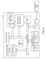
- FIG. 4 is a functional block diagram that illustrates a computing device 400 in accordance with some embodiments described herein.
- the computing device 400 may be a user device, such as the user device 110 shown in FIG. 1 .
- Computing device 400 may include at least one processor 402 and system memory 404 .
- computing system 400 may include a system bus 406 that communicatively connects processor 402 and system memory 404 , as well as other components of computing device 400 .
- the system memory 404 can be of any type of memory now known or later developed including but not limited to volatile memory (such as RAM), non-volatile memory (such as ROM, flash memory, etc.) or any combination thereof.
- An example computing device 400 may include various other components as well.
- computing device 400 includes an A/V processing unit 408 for controlling graphical display 410 , one or more communication interfaces 416 , and a power supply 420 .
- Graphical display 410 may be arranged to provide a visual depiction of various input regions provided by user-interface module 422 .
- User-interface module 422 may be further configured to receive data from and transmit data to (or be otherwise compatible with) one or more user-interface devices 428 , such as a keyboard, a mouse, among other examples.
- Computing device 400 may include one or more sensors 418 , which may gather data related to the computing device.
- the sensor(s) may include a global-positioning system (GPS) transceiver, one or more accelerometers, an inertial measurement unit (IMU), a compass, a speaker, and a camera. Other sensors are also possible.
- computing device 400 may also include one or more data storage devices 424 , which can be removable storage devices, non-removable storage devices, or a combination thereof.
- the computing device 400 may also include program instructions 426 that are stored in system memory 404 (and/or possibly in another data-storage medium) and executable by processor 402 to facilitate various operations. Although various components of computing device 400 are shown as distributed components, it should be understood that any of such components may be physically integrated and/or distributed according to the desired configuration of the computing system.
- Flow charts 500 and 700 shown in FIGS. 5 and 7 respectively, present example operations that may be implemented in the communications system 100 shown in FIG. 1 .
- Flow charts 500 and 700 may include one or more operations or actions as illustrated by one or more of the blocks shown in each figure. Although the blocks are illustrated in sequential order, these blocks may also be performed in parallel, and/or in a different order than those described herein. Also, the various blocks may be combined into fewer blocks, divided into additional blocks, and/or removed based upon the desired implementation.
- the indication of the request for satellite receiver data may take various forms.
- the input may indicate an HTTP request, such as a request for a webpage containing the satellite receiver data. Numerous other protocols for requesting and hosting information may also be used.
- the input may indicate a command to launch an application on the first computing device 400 , such as an ODU alignment application, that requests the satellite receiver data.
- the requested satellite receiver data may be one or more of a signal power measurement from one or more satellites, a signal-to-noise ratio, or a signal lock status, among other data.
- the satellite receiver data received from the second computing device 200 may also include the requested instruction for aligning the ODU 128 .
- the instruction may be determined by the second computing device 200 or another computing device.
- the first computing device 400 may determine the instruction based on the received satellite receiver data, and the determined instruction may be based on sensor data received from the one or more sensors, as discussed above.
- FIG. 6B shows the GUI 601 during the second step of the fine adjustment process.
- an indication 605 is displayed instructing the user to “Turn your adjustment screw 1 full turn COUNTER CLOCKWISE and click START TEST. Once the test finishes click NEXT.”
- Another indication 606 may be displayed on the GUI 601 showing the a representation of the direction that the screw should be turned. Accordingly, the user may turn the adjustment screw 1 full turn and click START TEST.
- a second measurement for the set of transponders may be obtained at the second orientation of the ODU 128 , and when the test is finished, the user may click NEXT to move to the next step.
- the request for the satellite receiver data may include a request to control the satellite receiver, such as a request to control a tuner of the STB 106 , as discussed above.
- the first computing device 300 may validate the request to control the satellite receiver.
- the second computing device 400 may need to be properly registered, or associated with a particular STB 106 , before it can makes requests to control the STB 106 .
- the first computing device 300 may verify that the request originated from a trusted device.
Abstract
Description
Claims (20)
Priority Applications (3)
| Application Number | Priority Date | Filing Date | Title |
|---|---|---|---|
| US14/586,777 US9521378B1 (en) | 2014-12-30 | 2014-12-30 | Remote display of satellite receiver information |
| US15/341,816 US9888217B2 (en) | 2014-12-30 | 2016-11-02 | Remote display of satellite receiver information |
| US15/861,331 US10805580B2 (en) | 2014-12-30 | 2018-01-03 | Remote display of satellite receiver information |
Applications Claiming Priority (1)
| Application Number | Priority Date | Filing Date | Title |
|---|---|---|---|
| US14/586,777 US9521378B1 (en) | 2014-12-30 | 2014-12-30 | Remote display of satellite receiver information |
Related Child Applications (1)
| Application Number | Title | Priority Date | Filing Date |
|---|---|---|---|
| US15/341,816 Continuation US9888217B2 (en) | 2014-12-30 | 2016-11-02 | Remote display of satellite receiver information |
Publications (1)
| Publication Number | Publication Date |
|---|---|
| US9521378B1 true US9521378B1 (en) | 2016-12-13 |
Family
ID=57484069
Family Applications (3)
| Application Number | Title | Priority Date | Filing Date |
|---|---|---|---|
| US14/586,777 Active US9521378B1 (en) | 2014-12-30 | 2014-12-30 | Remote display of satellite receiver information |
| US15/341,816 Active US9888217B2 (en) | 2014-12-30 | 2016-11-02 | Remote display of satellite receiver information |
| US15/861,331 Active 2035-03-13 US10805580B2 (en) | 2014-12-30 | 2018-01-03 | Remote display of satellite receiver information |
Family Applications After (2)
| Application Number | Title | Priority Date | Filing Date |
|---|---|---|---|
| US15/341,816 Active US9888217B2 (en) | 2014-12-30 | 2016-11-02 | Remote display of satellite receiver information |
| US15/861,331 Active 2035-03-13 US10805580B2 (en) | 2014-12-30 | 2018-01-03 | Remote display of satellite receiver information |
Country Status (1)
| Country | Link |
|---|---|
| US (3) | US9521378B1 (en) |
Cited By (6)
| Publication number | Priority date | Publication date | Assignee | Title |
|---|---|---|---|---|
| US20170064621A1 (en) * | 2013-05-29 | 2017-03-02 | Parallel Wireless, Inc. | Intelligent Mesh Network Selection |
| US20170070708A1 (en) * | 2014-12-30 | 2017-03-09 | The Directv Group, Inc. | Remote display of satellite receiver information |
| US20170373390A1 (en) * | 2016-06-28 | 2017-12-28 | Hong Fu Jin Precision Industry (Shenzhen) Co., Ltd | Satellite finding apparatus and satellite finding method |
| US11693529B2 (en) | 2021-08-31 | 2023-07-04 | Apple Inc. | Methods and interfaces for initiating communications |
| US11765114B2 (en) | 2017-05-16 | 2023-09-19 | Apple Inc. | Voice communication method |
| US11947784B2 (en) | 2016-06-11 | 2024-04-02 | Apple Inc. | User interface for initiating a telephone call |
Families Citing this family (1)
| Publication number | Priority date | Publication date | Assignee | Title |
|---|---|---|---|---|
| CN109639337B (en) * | 2018-11-23 | 2020-10-02 | 南京控维通信科技有限公司 | Graphic auxiliary satellite alignment method suitable for satellite communication equipment |
Citations (39)
| Publication number | Priority date | Publication date | Assignee | Title |
|---|---|---|---|---|
| US5313215A (en) | 1992-07-10 | 1994-05-17 | General Instrument Corporation | Satellite identification and antenna alignment |
| US5463403A (en) * | 1992-07-10 | 1995-10-31 | General Instrument Corporation | Automatic adjustment of receiver apparatus based on channel-bit-error-rate-affected parameter measurement |
| EP0548844B1 (en) * | 1991-12-20 | 1997-11-12 | Sony Corporation | Satellite broadcasting reception system |
| US5760739A (en) | 1996-08-14 | 1998-06-02 | Pauli; Richard A. | Method and apparatus for aiming a directional antenna |
| US5808583A (en) | 1995-03-13 | 1998-09-15 | Roberts; James M. | System for using sunshine and shadows to locate unobstructed satellite reception sites and for orientation of signal gathering devices |
| US5978716A (en) | 1997-05-28 | 1999-11-02 | Space Systems/Loral, Inc. | Satellite imaging control system for non-repeatable error |
| US6031507A (en) | 1998-02-06 | 2000-02-29 | Mitsubishi Denki Kabushiki Kaisha | Antenna apparatus |
| US20020000931A1 (en) | 2000-04-14 | 2002-01-03 | Mark Petronic | User interface for a two-way satellite communication system |
| US20020084941A1 (en) | 2000-12-29 | 2002-07-04 | Matz William R. | Antenna with integral alignment devices |
| US20030016172A1 (en) * | 2001-07-23 | 2003-01-23 | Mitsubishi Denki Kabushiki Kaisha | Satellite-tracking antenna controlling apparatus |
| US6535177B1 (en) | 1998-12-23 | 2003-03-18 | Manufacture D'appareillage Electrique De Cahors | Method and a device for pointing and positioning a multisatellite antenna |
| US6538612B1 (en) * | 1997-03-11 | 2003-03-25 | Lael D. King | Satellite locator system |
| US6600730B1 (en) | 1998-08-20 | 2003-07-29 | Hughes Electronics Corporation | System for distribution of satellite signals from separate multiple satellites on a single cable line |
| US6686889B1 (en) | 1998-12-08 | 2004-02-03 | Tae I. Kwon | Method and apparatus for antenna orientation and antenna with the same |
| US6693587B1 (en) | 2003-01-10 | 2004-02-17 | Hughes Electronics Corporation | Antenna/feed alignment system for reception of multibeam DBS signals |
| US20040128689A1 (en) * | 2001-06-05 | 2004-07-01 | Pugel Michael Anthony | Method and system for enabling channel set up in a television signal receiver |
| US6937188B1 (en) * | 2001-11-13 | 2005-08-30 | Bellsouth Intellectual Property Corporation | Satellite antenna installation tool |
| CN1700516A (en) | 2004-05-17 | 2005-11-23 | 启碁科技股份有限公司 | Rotation angle fine regulation mechanism and satellite antenna using the same |
| US20060020978A1 (en) * | 2004-07-23 | 2006-01-26 | Funai Electric Co., Ltd. | Digital television broadcast signal receiver |
| US7016643B1 (en) | 2003-01-10 | 2006-03-21 | The Directv Group, Inc. | Antenna positioning system and method for simultaneous reception of signals from a plurality of satellites |
| US20070080861A1 (en) | 2005-10-12 | 2007-04-12 | John Norin | Novel alignment method for multi-satellite consumer receiver antennas |
| US20070150923A1 (en) * | 2005-12-28 | 2007-06-28 | Funai Electric Co., Ltd. | Antenna system and television receiver |
| US20080018995A1 (en) | 2006-07-21 | 2008-01-24 | Baun Kenneth W | User-directed automated telescope alignment |
| US20080165070A1 (en) | 2007-01-09 | 2008-07-10 | The Directv Group, Inc. | Odu alignment procedure using circularly polarized signals allocated to specific satellites |
| US20090033576A1 (en) * | 2007-08-02 | 2009-02-05 | Embarq Holdings Company, Llc | System and method for re-aligning antennas |
| US7595764B2 (en) * | 2007-02-07 | 2009-09-29 | Wallace Technologies | Enclosed mobile/transportable satellite antenna system |
| US8260567B1 (en) | 2008-09-19 | 2012-09-04 | The United States Of America, As Represented By The Secretary Of The Navy | System and method for angles-only position and velocity determination using closed-form triangulation |
| US8296096B2 (en) | 2009-07-09 | 2012-10-23 | Richard Kirby | Positioning system and method using optically tracked anchor points |
| US20130127665A1 (en) * | 2011-11-18 | 2013-05-23 | Craig Miller | Satellite television antenna system |
| US20130135146A1 (en) * | 2011-11-29 | 2013-05-30 | Harris Corporation | Method for directed antenna alignment through augmented reality |
| US8554466B2 (en) | 2009-03-09 | 2013-10-08 | Mstar Semiconductor, Inc. | Ultraviolet detection system and method thereof |
| US20130271319A1 (en) * | 2012-04-12 | 2013-10-17 | Alan Trerise | Method and system for aiming and aligning self-installed broadcast signal receivers |
| US8837782B1 (en) | 2010-06-22 | 2014-09-16 | Lockheed Martin Corporation | Geoposition determination using satellite ephemerides |
| US20140315599A1 (en) | 2013-03-13 | 2014-10-23 | Flow Control Llc. | Methodology to define optimal sun position using the capability provided by smart phone technology |
| US8982004B1 (en) | 2007-08-03 | 2015-03-17 | The Directv Group, Inc. | Integrated ODU controller for antenna pointing |
| US20150219744A1 (en) | 2014-02-04 | 2015-08-06 | University Of Florida Research Foundation, Inc. | Robust integrated precision high-speed satellite attitude determination and control system (adcs) |
| US20150257126A1 (en) | 2014-03-04 | 2015-09-10 | Orbit Logic, Inc. | Method for Providing Imaging Satellite Opportunity Notifications on a Mobile Device |
| US20160036117A1 (en) | 2014-07-30 | 2016-02-04 | Echostar Technologies Llc | Method and apparatus for optimal antenna alignment |
| US20160056525A1 (en) | 2013-04-02 | 2016-02-25 | Telefonaktiebolaget L M Ericsson (Publ) | A Radio Antenna Alignment Tool |
Family Cites Families (5)
| Publication number | Priority date | Publication date | Assignee | Title |
|---|---|---|---|---|
| JP2005160078A (en) * | 2003-11-21 | 2005-06-16 | Thomson Licensing Sa | Receiving system including pointing auxiliary device |
| US7636067B2 (en) * | 2005-10-12 | 2009-12-22 | The Directv Group, Inc. | Ka/Ku antenna alignment |
| WO2014045495A1 (en) * | 2012-09-20 | 2014-03-27 | 日本電気株式会社 | Antenna orientation adjustment assistance device and antenna device installation method |
| US9451220B1 (en) * | 2014-12-30 | 2016-09-20 | The Directv Group, Inc. | System and method for aligning a multi-satellite receiver antenna |
| US9521378B1 (en) | 2014-12-30 | 2016-12-13 | The Directv Group, Inc. | Remote display of satellite receiver information |
-
2014
- 2014-12-30 US US14/586,777 patent/US9521378B1/en active Active
-
2016
- 2016-11-02 US US15/341,816 patent/US9888217B2/en active Active
-
2018
- 2018-01-03 US US15/861,331 patent/US10805580B2/en active Active
Patent Citations (41)
| Publication number | Priority date | Publication date | Assignee | Title |
|---|---|---|---|---|
| EP0548844B1 (en) * | 1991-12-20 | 1997-11-12 | Sony Corporation | Satellite broadcasting reception system |
| US5313215A (en) | 1992-07-10 | 1994-05-17 | General Instrument Corporation | Satellite identification and antenna alignment |
| US5463403A (en) * | 1992-07-10 | 1995-10-31 | General Instrument Corporation | Automatic adjustment of receiver apparatus based on channel-bit-error-rate-affected parameter measurement |
| US5808583A (en) | 1995-03-13 | 1998-09-15 | Roberts; James M. | System for using sunshine and shadows to locate unobstructed satellite reception sites and for orientation of signal gathering devices |
| US5760739A (en) | 1996-08-14 | 1998-06-02 | Pauli; Richard A. | Method and apparatus for aiming a directional antenna |
| US6538612B1 (en) * | 1997-03-11 | 2003-03-25 | Lael D. King | Satellite locator system |
| US5978716A (en) | 1997-05-28 | 1999-11-02 | Space Systems/Loral, Inc. | Satellite imaging control system for non-repeatable error |
| US6031507A (en) | 1998-02-06 | 2000-02-29 | Mitsubishi Denki Kabushiki Kaisha | Antenna apparatus |
| US6600730B1 (en) | 1998-08-20 | 2003-07-29 | Hughes Electronics Corporation | System for distribution of satellite signals from separate multiple satellites on a single cable line |
| US6686889B1 (en) | 1998-12-08 | 2004-02-03 | Tae I. Kwon | Method and apparatus for antenna orientation and antenna with the same |
| US6535177B1 (en) | 1998-12-23 | 2003-03-18 | Manufacture D'appareillage Electrique De Cahors | Method and a device for pointing and positioning a multisatellite antenna |
| US20020000931A1 (en) | 2000-04-14 | 2002-01-03 | Mark Petronic | User interface for a two-way satellite communication system |
| US20020084941A1 (en) | 2000-12-29 | 2002-07-04 | Matz William R. | Antenna with integral alignment devices |
| US20040128689A1 (en) * | 2001-06-05 | 2004-07-01 | Pugel Michael Anthony | Method and system for enabling channel set up in a television signal receiver |
| US20030016172A1 (en) * | 2001-07-23 | 2003-01-23 | Mitsubishi Denki Kabushiki Kaisha | Satellite-tracking antenna controlling apparatus |
| US6937188B1 (en) * | 2001-11-13 | 2005-08-30 | Bellsouth Intellectual Property Corporation | Satellite antenna installation tool |
| US6693587B1 (en) | 2003-01-10 | 2004-02-17 | Hughes Electronics Corporation | Antenna/feed alignment system for reception of multibeam DBS signals |
| US7016643B1 (en) | 2003-01-10 | 2006-03-21 | The Directv Group, Inc. | Antenna positioning system and method for simultaneous reception of signals from a plurality of satellites |
| CN1700516A (en) | 2004-05-17 | 2005-11-23 | 启碁科技股份有限公司 | Rotation angle fine regulation mechanism and satellite antenna using the same |
| US20060020978A1 (en) * | 2004-07-23 | 2006-01-26 | Funai Electric Co., Ltd. | Digital television broadcast signal receiver |
| US20070080861A1 (en) | 2005-10-12 | 2007-04-12 | John Norin | Novel alignment method for multi-satellite consumer receiver antennas |
| US20070150923A1 (en) * | 2005-12-28 | 2007-06-28 | Funai Electric Co., Ltd. | Antenna system and television receiver |
| US20080018995A1 (en) | 2006-07-21 | 2008-01-24 | Baun Kenneth W | User-directed automated telescope alignment |
| US20080165070A1 (en) | 2007-01-09 | 2008-07-10 | The Directv Group, Inc. | Odu alignment procedure using circularly polarized signals allocated to specific satellites |
| US7595764B2 (en) * | 2007-02-07 | 2009-09-29 | Wallace Technologies | Enclosed mobile/transportable satellite antenna system |
| US20090033576A1 (en) * | 2007-08-02 | 2009-02-05 | Embarq Holdings Company, Llc | System and method for re-aligning antennas |
| US8982004B1 (en) | 2007-08-03 | 2015-03-17 | The Directv Group, Inc. | Integrated ODU controller for antenna pointing |
| US8260567B1 (en) | 2008-09-19 | 2012-09-04 | The United States Of America, As Represented By The Secretary Of The Navy | System and method for angles-only position and velocity determination using closed-form triangulation |
| US8554466B2 (en) | 2009-03-09 | 2013-10-08 | Mstar Semiconductor, Inc. | Ultraviolet detection system and method thereof |
| US8296096B2 (en) | 2009-07-09 | 2012-10-23 | Richard Kirby | Positioning system and method using optically tracked anchor points |
| US8837782B1 (en) | 2010-06-22 | 2014-09-16 | Lockheed Martin Corporation | Geoposition determination using satellite ephemerides |
| US20130127665A1 (en) * | 2011-11-18 | 2013-05-23 | Craig Miller | Satellite television antenna system |
| US20150026737A1 (en) * | 2011-11-18 | 2015-01-22 | Electronic Controlled Systems, Inc. | Satellite television antenna system |
| US20130135146A1 (en) * | 2011-11-29 | 2013-05-30 | Harris Corporation | Method for directed antenna alignment through augmented reality |
| US9281559B2 (en) | 2011-11-29 | 2016-03-08 | Harris Corporation | Method for directed antenna alignment through augmented reality |
| US20130271319A1 (en) * | 2012-04-12 | 2013-10-17 | Alan Trerise | Method and system for aiming and aligning self-installed broadcast signal receivers |
| US20140315599A1 (en) | 2013-03-13 | 2014-10-23 | Flow Control Llc. | Methodology to define optimal sun position using the capability provided by smart phone technology |
| US20160056525A1 (en) | 2013-04-02 | 2016-02-25 | Telefonaktiebolaget L M Ericsson (Publ) | A Radio Antenna Alignment Tool |
| US20150219744A1 (en) | 2014-02-04 | 2015-08-06 | University Of Florida Research Foundation, Inc. | Robust integrated precision high-speed satellite attitude determination and control system (adcs) |
| US20150257126A1 (en) | 2014-03-04 | 2015-09-10 | Orbit Logic, Inc. | Method for Providing Imaging Satellite Opportunity Notifications on a Mobile Device |
| US20160036117A1 (en) | 2014-07-30 | 2016-02-04 | Echostar Technologies Llc | Method and apparatus for optimal antenna alignment |
Cited By (12)
| Publication number | Priority date | Publication date | Assignee | Title |
|---|---|---|---|---|
| US20170064621A1 (en) * | 2013-05-29 | 2017-03-02 | Parallel Wireless, Inc. | Intelligent Mesh Network Selection |
| US10327201B2 (en) * | 2013-05-29 | 2019-06-18 | Parallel Wireless, Inc. | Mesh network selection and antenna alignment |
| US20170070708A1 (en) * | 2014-12-30 | 2017-03-09 | The Directv Group, Inc. | Remote display of satellite receiver information |
| US9888217B2 (en) * | 2014-12-30 | 2018-02-06 | The Directv Group, Inc | Remote display of satellite receiver information |
| US20180146172A1 (en) * | 2014-12-30 | 2018-05-24 | The Directv Group, Inc. | Remote display of satellite receiver information |
| US10805580B2 (en) * | 2014-12-30 | 2020-10-13 | The Directv Group, Inc. | Remote display of satellite receiver information |
| US11947784B2 (en) | 2016-06-11 | 2024-04-02 | Apple Inc. | User interface for initiating a telephone call |
| US20170373390A1 (en) * | 2016-06-28 | 2017-12-28 | Hong Fu Jin Precision Industry (Shenzhen) Co., Ltd | Satellite finding apparatus and satellite finding method |
| US10389022B2 (en) * | 2016-06-28 | 2019-08-20 | Nanning Fugui Precision Industrial Co., Ltd. | Satellite finding apparatus and satellite finding method |
| US11765114B2 (en) | 2017-05-16 | 2023-09-19 | Apple Inc. | Voice communication method |
| US11693529B2 (en) | 2021-08-31 | 2023-07-04 | Apple Inc. | Methods and interfaces for initiating communications |
| US11893203B2 (en) * | 2021-08-31 | 2024-02-06 | Apple Inc. | Methods and interfaces for initiating communications |
Also Published As
| Publication number | Publication date |
|---|---|
| US10805580B2 (en) | 2020-10-13 |
| US20170070708A1 (en) | 2017-03-09 |
| US9888217B2 (en) | 2018-02-06 |
| US20180146172A1 (en) | 2018-05-24 |
Similar Documents
| Publication | Publication Date | Title |
|---|---|---|
| US10805580B2 (en) | Remote display of satellite receiver information | |
| TWI482362B (en) | Antenna orientation determination | |
| US9800942B2 (en) | Systems and methods for positioning a satellite uplink device | |
| EP3092548B1 (en) | Systems and methods of displaying integrated home automation modules | |
| US20130271319A1 (en) | Method and system for aiming and aligning self-installed broadcast signal receivers | |
| US9277271B2 (en) | Wireless network antenna apparatus and method | |
| KR102309586B1 (en) | Decentralized Indoor Smart Antenna System for OTA Television Reception | |
| WO2015104861A1 (en) | Satellite communication system | |
| KR20200043167A (en) | Apparatus for pament system and method of operating pament system | |
| White et al. | SatNOGS: satellite networked open ground station | |
| US20190082230A1 (en) | Controlling internet of things (iot) devices and aggregating media content through a common device | |
| JP2024506459A (en) | ATSC 3.0 Long Term Error Correction with Fast Channel Change for Real-Time Broadcast Mobile Applications | |
| US9451220B1 (en) | System and method for aligning a multi-satellite receiver antenna | |
| RU2690100C2 (en) | Method of installing an outdoor unit using an electronic device and an electronic device for such an installation | |
| US20190327520A1 (en) | Set-Top Box with Enhanced Content and System and Method for Use of Same | |
| US9674306B2 (en) | Method and system for communicating from a client device to a server device in a centralized content distribution system | |
| US9854071B2 (en) | Redundant, low-latency digital audio transmission | |
| US9661399B2 (en) | Methods and apparatus for presenting a still-image feedback response to user command for remote audio/video content viewing | |
| KR101791847B1 (en) | Method and apparatus for providing additional information for a viewer to watch a one-way broadcast | |
| KR20190123174A (en) | Set top box, and control method thereof | |
| FR3026018A1 (en) | METHOD FOR BI-DIRECTIONAL TRANSMISSION OF CONTINUOUS VIDEO STREAMS AND DATA BETWEEN AN AUTOMATED DRONE AND A SET OF INTERNET CONNECTED TERMINALS | |
| US20210185406A1 (en) | Satellite communication system and satellite communication method | |
| EP2429029A1 (en) | Broadcast receiving apparatus, image output method, and program | |
| US20180227628A1 (en) | Entertainment Center Technical Configuration and System and Method for Use of Same | |
| US20170171591A1 (en) | Unilateral Transmission Of Second Screen Information In Proximity Of A First Screen |
Legal Events
| Date | Code | Title | Description |
|---|---|---|---|
| AS | Assignment |
Owner name: THE DIRECTV GROUP, INC., CALIFORNIA Free format text: ASSIGNMENT OF ASSIGNORS INTEREST;ASSIGNORS:PALAGANAS, CHARLES P.;WU, TERENCE;REEL/FRAME:034668/0320 Effective date: 20150108 |
|
| FEPP | Fee payment procedure |
Free format text: PAYOR NUMBER ASSIGNED (ORIGINAL EVENT CODE: ASPN); ENTITY STATUS OF PATENT OWNER: LARGE ENTITY |
|
| STCF | Information on status: patent grant |
Free format text: PATENTED CASE |
|
| MAFP | Maintenance fee payment |
Free format text: PAYMENT OF MAINTENANCE FEE, 4TH YEAR, LARGE ENTITY (ORIGINAL EVENT CODE: M1551); ENTITY STATUS OF PATENT OWNER: LARGE ENTITY Year of fee payment: 4 |
|
| AS | Assignment |
Owner name: DIRECTV, LLC, CALIFORNIA Free format text: ASSIGNMENT OF ASSIGNORS INTEREST;ASSIGNOR:THE DIRECTV GROUP, INC.;REEL/FRAME:057323/0150 Effective date: 20210728 |
|
| AS | Assignment |
Owner name: CREDIT SUISSE AG, CAYMAN ISLANDS BRANCH, AS COLLATERAL AGENT, NEW YORK Free format text: SECURITY AGREEMENT;ASSIGNOR:DIRECTV, LLC;REEL/FRAME:057695/0084 Effective date: 20210802 |
|
| AS | Assignment |
Owner name: THE BANK OF NEW YORK MELLON TRUST COMPANY, N.A. AS COLLATERAL AGENT, TEXAS Free format text: SECURITY AGREEMENT;ASSIGNOR:DIRECTV, LLC;REEL/FRAME:058220/0531 Effective date: 20210802 |
|
| AS | Assignment |
Owner name: THE BANK OF NEW YORK MELLON TRUST COMPANY, N.A., AS COLLATERAL AGENT, TEXAS Free format text: SECURITY AGREEMENT;ASSIGNOR:DIRECTV, LLC;REEL/FRAME:066371/0690 Effective date: 20240124 |