US9523479B2 - LED lens - Google Patents
LED lens Download PDFInfo
- Publication number
- US9523479B2 US9523479B2 US14/147,268 US201414147268A US9523479B2 US 9523479 B2 US9523479 B2 US 9523479B2 US 201414147268 A US201414147268 A US 201414147268A US 9523479 B2 US9523479 B2 US 9523479B2
- Authority
- US
- United States
- Prior art keywords
- lens
- emitter
- light
- tir
- edge
- Prior art date
- Legal status (The legal status is an assumption and is not a legal conclusion. Google has not performed a legal analysis and makes no representation as to the accuracy of the status listed.)
- Active, expires
Links
- 230000003287 optical effect Effects 0.000 claims description 10
- 238000009792 diffusion process Methods 0.000 abstract description 5
- 238000005286 illumination Methods 0.000 description 6
- 238000003491 array Methods 0.000 description 5
- 239000003086 colorant Substances 0.000 description 2
- 230000007423 decrease Effects 0.000 description 2
- 230000003247 decreasing effect Effects 0.000 description 2
- 230000000694 effects Effects 0.000 description 2
- 238000009877 rendering Methods 0.000 description 2
- 230000009286 beneficial effect Effects 0.000 description 1
- 230000007717 exclusion Effects 0.000 description 1
- 238000004519 manufacturing process Methods 0.000 description 1
- 238000000465 moulding Methods 0.000 description 1
Images


Classifications
-
- F—MECHANICAL ENGINEERING; LIGHTING; HEATING; WEAPONS; BLASTING
- F21—LIGHTING
- F21V—FUNCTIONAL FEATURES OR DETAILS OF LIGHTING DEVICES OR SYSTEMS THEREOF; STRUCTURAL COMBINATIONS OF LIGHTING DEVICES WITH OTHER ARTICLES, NOT OTHERWISE PROVIDED FOR
- F21V5/00—Refractors for light sources
- F21V5/04—Refractors for light sources of lens shape
-
- F—MECHANICAL ENGINEERING; LIGHTING; HEATING; WEAPONS; BLASTING
- F21—LIGHTING
- F21V—FUNCTIONAL FEATURES OR DETAILS OF LIGHTING DEVICES OR SYSTEMS THEREOF; STRUCTURAL COMBINATIONS OF LIGHTING DEVICES WITH OTHER ARTICLES, NOT OTHERWISE PROVIDED FOR
- F21V5/00—Refractors for light sources
- F21V5/08—Refractors for light sources producing an asymmetric light distribution
-
- F—MECHANICAL ENGINEERING; LIGHTING; HEATING; WEAPONS; BLASTING
- F21—LIGHTING
- F21V—FUNCTIONAL FEATURES OR DETAILS OF LIGHTING DEVICES OR SYSTEMS THEREOF; STRUCTURAL COMBINATIONS OF LIGHTING DEVICES WITH OTHER ARTICLES, NOT OTHERWISE PROVIDED FOR
- F21V7/00—Reflectors for light sources
- F21V7/0091—Reflectors for light sources using total internal reflection
-
- G—PHYSICS
- G02—OPTICS
- G02B—OPTICAL ELEMENTS, SYSTEMS OR APPARATUS
- G02B19/00—Condensers, e.g. light collectors or similar non-imaging optics
- G02B19/0033—Condensers, e.g. light collectors or similar non-imaging optics characterised by the use
- G02B19/0047—Condensers, e.g. light collectors or similar non-imaging optics characterised by the use for use with a light source
- G02B19/0061—Condensers, e.g. light collectors or similar non-imaging optics characterised by the use for use with a light source the light source comprising a LED
-
- G—PHYSICS
- G02—OPTICS
- G02B—OPTICAL ELEMENTS, SYSTEMS OR APPARATUS
- G02B3/00—Simple or compound lenses
-
- F—MECHANICAL ENGINEERING; LIGHTING; HEATING; WEAPONS; BLASTING
- F21—LIGHTING
- F21Y—INDEXING SCHEME ASSOCIATED WITH SUBCLASSES F21K, F21L, F21S and F21V, RELATING TO THE FORM OR THE KIND OF THE LIGHT SOURCES OR OF THE COLOUR OF THE LIGHT EMITTED
- F21Y2101/00—Point-like light sources
-
- F—MECHANICAL ENGINEERING; LIGHTING; HEATING; WEAPONS; BLASTING
- F21—LIGHTING
- F21Y—INDEXING SCHEME ASSOCIATED WITH SUBCLASSES F21K, F21L, F21S and F21V, RELATING TO THE FORM OR THE KIND OF THE LIGHT SOURCES OR OF THE COLOUR OF THE LIGHT EMITTED
- F21Y2105/00—Planar light sources
- F21Y2105/10—Planar light sources comprising a two-dimensional array of point-like light-generating elements
-
- F—MECHANICAL ENGINEERING; LIGHTING; HEATING; WEAPONS; BLASTING
- F21—LIGHTING
- F21Y—INDEXING SCHEME ASSOCIATED WITH SUBCLASSES F21K, F21L, F21S and F21V, RELATING TO THE FORM OR THE KIND OF THE LIGHT SOURCES OR OF THE COLOUR OF THE LIGHT EMITTED
- F21Y2113/00—Combination of light sources
- F21Y2113/10—Combination of light sources of different colours
- F21Y2113/13—Combination of light sources of different colours comprising an assembly of point-like light sources
-
- F—MECHANICAL ENGINEERING; LIGHTING; HEATING; WEAPONS; BLASTING
- F21—LIGHTING
- F21Y—INDEXING SCHEME ASSOCIATED WITH SUBCLASSES F21K, F21L, F21S and F21V, RELATING TO THE FORM OR THE KIND OF THE LIGHT SOURCES OR OF THE COLOUR OF THE LIGHT EMITTED
- F21Y2115/00—Light-generating elements of semiconductor light sources
- F21Y2115/10—Light-emitting diodes [LED]
-
- H—ELECTRICITY
- H01—ELECTRIC ELEMENTS
- H01L—SEMICONDUCTOR DEVICES NOT COVERED BY CLASS H10
- H01L33/00—Semiconductor devices with at least one potential-jump barrier or surface barrier specially adapted for light emission; Processes or apparatus specially adapted for the manufacture or treatment thereof or of parts thereof; Details thereof
- H01L33/48—Semiconductor devices with at least one potential-jump barrier or surface barrier specially adapted for light emission; Processes or apparatus specially adapted for the manufacture or treatment thereof or of parts thereof; Details thereof characterised by the semiconductor body packages
- H01L33/58—Optical field-shaping elements
Definitions
- This invention relates generally to the field of LED lighting apparatus and, more particularly, to the field of LED-based optical systems for use in LED lighting fixtures for which there are particular light-distribution requirements, such as what is sometimes referred to as preferential-side light distribution—for roadway light fixtures and the like.
- LEDs light-emitting diodes
- HID high-intensity discharge
- fixtures for roadway lighting an application in which the fixtures are generally placed along roadway edges while light distribution is desired along a significant portion of roadway length and, of course, on the roadway itself—generally to the exclusion of significant light off the roadway.
- Providing roadway light from light fixtures along the roadway may be referred to as “preferential-side” illumination.
- preferential-side illumination it is desirable to minimize the use of large complex reflectors and/or varying orientations of multiple light sources to achieve desired illumination patterns.
- Achieving preferential-side illumination, or other desired illumination patterns, by means of LED-based optical systems, particularly without resorting to large complex reflectors or other complex means is highly desirable.
- the present invention is a lens for distribution of light from a light emitter having an emitter axis.
- the lens has an outer surface and a total internal reflection (TIR) surface positioned outwardly of and around the emitter such that light received by the TIR surface is totally internally reflected toward the outer surface.
- the TIR surface includes at least one recessed region extending away from the light emitter, thereby to increase amount of TIR and facilitate lateral diffusion of highest-intensity light in the middle of the light distribution.
- the TIR surface is substantially cross-sectionally convex. In some of such embodiments, the TIR surface comprises at least two cross-sectionally convex surface portions with the recessed region therebetween.
- TIR surface reflects light at greater angles which provides a wider lateral light distribution and beneficial lateral diffusion of highest-intensity light in the middle of the light distribution. This facilitates uniformity of the resulting light pattern.
- the critical TIR angle is smaller at the surface with the greater curvature which broadens the range of angles for reflection of light that reaches the TIR surface. Consequently, more light that reaches TIR surface is usefully reflected instead of passing through the TIR surface, thereby facilitating efficiency of the lens.
- the recessed region may be substantially cross-sectionally smoothly concave and smoothly adjoin adjacent convex portions of the TIR surface.
- the lens is configured for distributing light from the light emitter predominantly toward a preferential side.
- the TIR surface is centered substantially on the non-preferential side to redirect light therefrom toward the preferential side.
- the TIR surface spans an angle in the range 90-180° around the emitter axis.
- the TIR surface may span about 140° around the emitter axis.
- the lens further includes a refracting inner surface configured for refracting light from the light emitter predominantly toward a preferential side.
- the inner surface defines an inner cavity about the emitter axis.
- the refracting inner surface may have front and back sectors.
- the front sector is centered on the preferential side and refracts emitter light predominantly toward the outer surface.
- the back sector is centered on the non-preferential side radially opposite the preferential side and has a back-sector surface configuration which differs from the surface configuration of the front sector.
- the lens has a base surface adjacent the emitter and forming an opening about the emitter.
- the inner surface extends from the opening.
- the TIR surface partially bounds a secondary cavity which is offset from the inner cavity.
- the secondary cavity is offset from the inner cavity with an intermediate surface therebetween.
- the intermediate surface including front and rear edges with a pair of side edges therebetween, the TIR surface extending from the rear edge of the intermediate surface.
- the rear edge of the intermediate surface may be shaped by at least two convex edge portions each extending from the respective side edge toward a front-to-rear centerline and inwardly toward the emitter axis, thereby forming a recessed edge portion on the centerline.
- the recessed edge portion may be substantially smoothly concave and smoothly adjoins adjacent convex edge portions.
- the convex edge portions define two central tangent lines transverse to the centerline.
- the angle between the central tangent lines is less than 180°.
- the convex edge portions define two side tangent lines transverse to the centerline. In certain examples, the angle between the side tangent lines is less than the angle between the central tangent lines.
- the TIR surface terminates at a distal edge of substantially continuous convex configuration.
- the secondary cavity may be further partially bounded by an axially-remote surface extending from the base surface toward the TIR surface and offset therefrom by an end surface which extends from the distal edge of the TIR surface to an axially-remote surface.
- the intermediate surface may be substantially orthogonal to the emitter axis.
- the back sector of the inner surface extends from the front edge of the intermediate surface.
- the front edge of the intermediate surface is shaped by at least two convex front-edge portions each extending from the respective side edge toward the front-to-rear centerline and inwardly toward the emitter axis, thereby forming a recessed front-edge portion on the centerline.
- the convex front-edge portions define two front-edge central tangent lines transverse to the centerline, the angle between the front-edge central tangent lines being less than 180°. In some of such embodiments, the convex edge portions define two front-edge side tangent lines transverse to the centerline. In certain versions, the angle between the front-edge side tangent lines is less than the angle between the front-edge central tangent lines.
- the front edge of the intermediate surface is substantially equidistant from the rear edge at positions along radii from the emitter axis.
- the outer surface may be configured for refracting emitter light predominantly toward the preferential side.
- the outer surface has a non-convex region substantially over the TIR surface configured to further refract light received from the TIR surface.
- the lens may further include an outward flange extending from the outer surface away from the axis.
- Another aspect of the present invention is a light fixture including a heat-sink structure having a mounting surface.
- a circuit board is on the mounting surface and supports a plurality of light emitters spaced thereon.
- An optical member is positioned over the circuit board and has a plurality of the lenses each in alignment with a corresponding one of the emitters.
- the light emitter may be an LED emitter which may include a single LED or a closely-spaced group of LEDs mounted either directly on the board (e.g., a circuit board) or in the form of an LED package with the LED(s) on a submount on the board.
- the LED emitter may include what is commonly referred to as a primary lens over the LED(s).
- the inventive lens is a so-called secondary lens placed over the primary lens.
- the lens according to the present invention may be the primary lens directly over the LED(s).
- transverse as used herein in reference to the tangent lines with respect to the emitter axis, means that the tangent lines intersect the emitter axis.
- FIG. 1 is a front perspective view of one embodiment of the lens of the present invention showing the lens over a light emitter.
- FIGS. 2 and 3 are rear perspective views showing the lens of FIG. 1 with surface shading.
- FIG. 4 is a cross-sectional perspective view of the lens of FIG. 3 taken along section 4 - 4 as shown in FIG. 3 .
- FIG. 5 is the cross-sectional view as in FIG. 4 , but shown with surface shading.
- FIG. 6 is a front elevation of the lens of FIGS. 1-5 .
- FIG. 7 is an inside-surface transparent plan view of an example of a prior lens.
- FIG. 8 is an inside-surface transparent plan view of the lens of FIG. 1 , showing the geometric configuration of light-modifying surfaces surrounding the emitter.
- FIG. 9 is an inside-surface transparent plan view of the lens as in FIG. 8 , but shown with markings of the geometric shapes of the intermediate surface of the lens.
- FIG. 10 is a side elevation of the lens of FIG. 1 with rays representing direction of light by the lens surfaces in plane 10 - 10 as indicated in FIG. 2 .
- FIG. 11 is an opaque cross-sectional view of the lens of FIG. 1 taken along plane 10 - 10 as indicated in FIG. 2 .
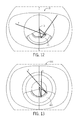
- FIG. 12 is a shaded plan view of a lens according to the present invention seen from the light-output side and schematically illustrating examples of directions of light reflected from the TIR surface according to the present invention.
- FIG. 13 is a shaded plan view similar to FIG. 12 , but of an alternative lens with a smooth TIR surface, schematically illustrating examples of directions of light reflected from a smooth TIR surface.
- FIG. 14 is a shaded side elevation of the lens of FIG. 12 schematically illustrating an example of light reflected from the TIR surface according to the present invention.
- FIG. 15 is a shaded side view of the lens of FIG. 13 schematically illustrating an example of light passing through the smooth TIR surface.
- FIG. 16 is a plan view of a lens according to the present invention seen from the light output side and schematically illustrating the light distribution by the lens.
- FIG. 17 is a plan view similar to FIG. 16 , but of a prior lens, schematically illustrating the light distribution by such prior lens.
- FIG. 18 is a front elevation the lens of FIG. 16 schematically illustrating light distribution by the lens.
- FIG. 19 is a front elevation of the prior lens of FIG. 17 schematically illustrating light distribution by such prior lens.
- FIG. 20 is a schematic two-dimensional ISO plot of luminance intensity by the lens FIGS. 16 and 18 on an illuminated surface substantially normal to the emitter axis.
- FIG. 21 is a two-dimensional ISO plot of luminance intensity by the prior lens of FIGS. 17 and 19 on an illuminated surface substantially normal to the emitter axis.
- FIG. 22 is a luminance rendering of light distribution by the lens of FIGS. 16 and 18 on an illuminated surface substantially normal to the emitter axis.
- FIG. 23 is a luminance rendering of light distribution by the prior lens of FIGS. 17 and 19 on an illuminated surface substantially normal to the emitter axis.
- FIGS. 24 and 26 are opaque rear perspective views of the lens of FIG. 1 , showing a non-convex region of the outer surface of the lens.
- FIG. 25 is an opaque cross-sectional view of the lens of FIG. 1 taken along plane 25 - 25 shown on FIG. 26 .
- FIG. 27 is an enlarged perspective view of one example of an LED package and including an array of eight LEDs on a submount and an asymmetric primary lens overmolded over the LED array.
- FIG. 28 is an enlarged perspective view of another example of an LED package and including an array of forty-eight LEDs on a submount and an asymmetric primary lens overmolded over the LED array.
- FIG. 29 is an enlarged perspective of yet another example of an LED package which has a single LED on a submount with a hemispheric primary lens overmolded over the LED.
- FIG. 30 is an enlarged side view of the LED package of FIG. 29 .
- FIG. 31 is an enlarged top view of the LED package of FIG. 29 .
- FIG. 32 is an enlarged top view of another exemplary LED package including an array of four LEDs on a submount and a hemispheric primary lens overmolded over the LED array such that the axis of the primary lens is offset from the axis of the LED array.
- FIG. 33 is a side elevation of one embodiment of a lighting apparatus including a one-piece lensing member incorporating a plurality of the lenses each according to the present invention.
- FIG. 34 is a plan view from the light-output side of the lighting apparatus of FIG. 33 .
- FIG. 35 is a plan view from the light-emitter side of the lighting apparatus of FIG. 33 .
- FIG. 36 is a perspective view of a light fixture incorporating an optical member with a plurality of lenses each according to the present invention.
- FIG. 37 is a plan view of the light fixture of FIG. 36 .
- FIG. 38 is a fragmentary cross-sectional view of the light fixture of FIG. 36 taken along plane 38 - 38 shown on FIG. 37 .
- FIG. 39 is a fragmentary cross-sectional view of the light fixture of FIG. 36 taken along plane 39 - 39 shown on FIG. 37 .
- FIGS. 1-6, 8-12, 16, 18, 20, 22 and 24-26 show aspects of an exemplary embodiment of a lens 10 in accordance with this invention.
- Lens 10 is configured for distribution of light from a light emitter 20 having an emitter axis 11 .
- the LED emitter may include a single LED (or a closely-spaced group of LEDs) mounted either directly on a circuit board or in the form of an LED package with the LED(s) on a submount on the board.
- a primary lens may be disposed directly over the LED(s).
- the primary lens over the LED(s) may be a lens according to the present invention.
- lens 10 is a secondary lens placed over the primary lens as seen in FIGS. 1 and 10 .
- Lens 10 has an outer surface 30 and a total internal reflection (TIR) surface 40 positioned outwardly of and around emitter 20 such that light received by TIR surface 40 is totally internally reflected toward outer surface 30 .
- TIR surface 40 includes at least one recessed region 41 extending away from light emitter 20 .
- FIGS. 8 and 9 show that TIR surface 40 is substantially cross-sectionally convex.
- FIGS. 4, 5, 8, 9 and 12 also show TIR surface 40 having two cross-sectionally convex surface portions 42 with recessed region 41 therebetween.
- FIG. 8 best shows recessed region 41 substantially cross-sectionally smoothly concave and smoothly adjoining adjacent convex portions 42 of TIR surface 40 .
- FIGS. 12, 13 and 16-23 illustrate that recessed region 41 of TIR surface 40 also facilitates lateral diffusion of highest-intensity light in the middle of the light distribution.
- FIG. 9 illustrates that the presence of recessed region 41 decreases radii of curvature of convex portions 42 which increases the curvature at each particular point as compared to curvature 43 of entire TIR surface 40 . Due to such increased curvature, TIR surface 40 reflects light at angles which are greater than angles of an alternative lens 10 C with a smooth TIR surface 40 C seen in FIG. 13 .
- FIGS. 16-23 show comparisons of performance of lens 10 of the present invention with a prior lens 10 A.
- FIG. 16 shows that greater TIR angles of lens 10 of the present invention provide a wider forward light distribution than prior lens 10 A, as seen in FIG. 17 .
- FIG. 18 illustrates a light output with a the cris-cross effect X caused by recessed region 41 of TIR surface 40 as compared to light output by prior lens 10 A, as illustrated in FIG. 19 .
- FIGS. 20 and 22 illustrate that such cris-cross effect provides a desirable diffusion of light A in the center of the distribution where the highest intensity of light naturally occurs. The result is less density of axial light A when compared to distribution by prior lens 10 A, as illustrated in FIGS. 21 and 23 .
- FIG. 20 and 21 schematically illustrate Type III distribution at 4800 lumens (lm).
- light distribution by prior lens 10 A with a smooth TIR surface 40 A includes a so-called “hot spot” H of 1.37 foot candles (fc).
- H 1.37 foot candles
- lens 10 with TIR surface 40 of the present invention diffuses hot spot H 1 to a wider pattern H 2 which is only 0.83 fc. This facilitates uniformity of the resulting light pattern with a smoother distribution (seen in FIG. 22 ) that is more pleasing to the eye than prior distribution with greater contrasts between the areas of light distribution, as seen in FIG. 23 .
- FIG. 15 shows alternative lens 10 C with a smooth TIR surface 40 C.
- emitter light reaches such smooth TIR surface, it is typically reflected at substantially high angles which direct such light substantially along the emitter axis toward the “hot spot” area.
- FIG. 15 illustrates that one way to attempt diffusing light that arrives at the middle region of the TIR surface is to decrease the angle of TIR surface 40 C such to direct such light forward away from the “hot spot” area.
- FIG. 15 illustrates that one way to attempt diffusing light that arrives at the middle region of the TIR surface is to decrease the angle of TIR surface 40 C such to direct such light forward away from the “hot spot” area.
- FIG. 15 illustrates that one way to attempt diffusing light that arrives at the middle region of the TIR surface is to decrease the angle of TIR surface 40 C such to direct such light forward away from the “hot spot” area.
- FIG. 15 illustrates that one way to attempt diffusing light that arrives at the middle region of the TIR surface is to decrease the angle of TIR surface 40 C such
- TIR surface 40 C shows that, if the angle of the TIR surface is decreased too much, light reaches TIR surface 40 C at angles below the critical angle for total internal reflection and just passes through TIR surface 40 C. As a result, such light is lost for useful illumination.
- the critical TIR angle is smaller, thereby broadening the range of angles for reflection of light that reaches TIR surface 40 instead of such light passing through, thereby facilitating efficiency of the lens.
- lens 10 is configured for distributing light from light emitter 20 predominantly toward a preferential side P.
- TIR surface 40 is centered substantially on a non-preferential side N, which is opposite preferential side P, to redirect light toward preferential side P.
- the TIR surface may span an angle in the range 90-180° around emitter axis 11 .
- TIR surface 40 is shown spanning about 140° around emitter axis 11 .
- FIG. 10 best shows that lens 10 includes a refracting inner surface 50 configured for refracting light from light emitter 20 predominantly toward preferential side P.
- inner surface 50 defines an inner cavity 51 about emitter axis 11 .
- refracting inner surface 50 has a front sector 52 and a back sector 53 .
- Front sector 52 is centered on preferential side P and refracts emitter light predominantly toward outer surface 30 .
- back sector 53 is centered on non-preferential N side radially opposite preferential side P and has a back-sector surface configuration 54 which differs from the surface configuration of front sector 52 .
- FIGS. 6 and 11 show that lens 10 has a base surface 13 adjacent an emitter plane 14 defined by a surface supporting emitter 20 .
- Base surface 13 forms an opening 15 about emitter 20 .
- FIGS. 6 and 11 show inner surface 50 extending from opening 15 .
- FIGS. 10 and 11 show TIR surface 40 partially bounding a secondary cavity 16 which is offset from inner cavity 51 .
- FIGS. 1-5 and 11 show TIR surface 40 terminating remotely from base surface 13 at a distal edge 45 .
- FIGS. 1-5 show distal edge 45 having substantially continuous convex configuration.
- Secondary cavity 40 is also partially bounded by an axially-remote surface 46 extending from base surface 13 toward TIR surface 40 and offset therefrom by an end surface 47 which extends from distal edge 45 of TIR surface 40 to axially-remote surface 46 .
- secondary cavity 44 is offset from inner cavity 51 with an intermediate surface 60 therebetween.
- Intermediate surface 60 is shown to be substantially orthogonal to emitter axis 11 .
- intermediate surface 60 includes a front edge 61 and a rear edge 62 with a pair of side edges 63 therebetween.
- TIR surface 40 extends from rear edge 62 of intermediate surface 60 .
- rear edge 62 of intermediate surface 60 is shaped by two convex edge portions 64 each extending from the respective side edge 63 toward a front-to-rear centerline 16 and inwardly toward emitter axis 11 , thereby forming a recessed edge portion 65 on centerline 16 .
- Recessed edge portion 65 is shown substantially smoothly concave and smoothly adjoining adjacent convex edge portions 64 .
- convex edge portions 64 define two central tangent lines 66 transverse to centerline 16 .
- the angle 67 between central tangent lines 66 is less than 180°.
- Convex edge portions 64 are shown to define two side tangent lines 68 transverse to centerline.
- FIG. 9 shows that the angle 69 between side tangent lines 68 is less than angle 67 between central tangent lines 66 .
- the intermediate surface may be configured such that the side tangent lines are substantially parallel to the centerline.
- the intermediate surface may be configured such that the side tangent lines define such angle therebetween which is greater than the angle between the central tangent lines.
- FIGS. 4, 5 and 11 best show back sector 53 of inner surface 50 extending from front edge 61 of intermediate surface 60 .
- front edge 61 of intermediate surface 60 is shaped by two convex front-edge portions 72 each extending from respective side edge 63 toward front-to-rear centerline 16 and inwardly toward emitter axis 11 , thereby forming a recessed front-edge portion 73 on centerline 16 .
- emitter axis is offset from front-edge portion 73 toward preferential side P.
- FIG. 8 shows that front edge 61 of intermediate surface 60 is substantially equidistant from rear edge 62 at positions along radii from emitter axis 11 .
- outer surface 30 is seen configured for refracting emitter light predominantly toward preferential side P.
- FIGS. 24-26 show outer surface 30 having a non-convex region 31 positioned substantially over TIR surface 40 .
- Non-convex region 31 may be configured to have a minimal curvature or even be substantially flat such that light received from TIR surface 40 is further refracted by outer surface 30 .
- the curvature of the non-convex outer surface region is configured to create high critical TIR angles of incidence for light reflected from the TIR surface in order to minimize total internal reflection of such light from the outer-surface region back into the lens.
- Lens 10 is shown to have an outward flange 32 which extends from outer surface 30 away from emitter axis 11 .
- inventive lens 10 allows for molding of lens 10 in a single-piece mold.
- the lens configuration preferably permits easy removal of the lens from the mold without the need for separating the mold pieces as is the case with some lenses that require multiple-piece molds.
- the inventive lens can be simply pulled out of the mold.
- FIGS. 33-35 show lighting apparatus 80 which includes a plurality of lenses 10 B according to the present invention.
- Lighting apparatus is configured for use with a plurality of LED light emitters spaced along a circuit board, each of the LED light emitters defining an axis, each lens 10 B corresponding to one of the LED light emitters.
- Lighting apparatus 80 may be a one-piece member which includes a plurality of lens portions interconnected by a single flange member, each of the lens portions including one of the plurality of lenses according to the present invention.
- lighting apparatus 80 may be a one-piece optical member which has a polymeric carrier portion surrounding a plurality of lenses, each according to the present invention. Such carrier portion overlaps with and is molded onto the lens flanges across such overlapping.
- Such one-piece optical member and a method of manufacturing are described in detail in application Ser. No. 13/843,649, filed Mar. 15, 2013, the entire contents of which are incorporated herein by reference.
- a plurality of LEDs or LED arrays may be disposed directly on a common submount in spaced relationship between the LEDs or LED arrays. This type of LED emitters is sometimes referred to as chip-on-board LEDs.
- each of LEDs is on a submount and each of the submounts is mounted on the circuit board.
- each of the LEDs or LED arrays may be overmolded with a respective primary lens.
- a lens according to the present invention may form the primary lens over a respective one of the LEDs or LED arrays.
- a plurality of inventive lenses form secondary lenses each over a respective one primary lenses.
- the plurality of the inventive lenses may be molded as a single piece which my have a single flange surrounding each of the plurality of lenses 10 B, as seen in FIGS. 33-35 .
- FIGS. 39-39 illustrate an example of a light fixture 90 incorporating the present invention.
- Fixture 90 includes a heat-sink structure 91 having a mounting surface 92 with a circuit board 27 on such mounting surface 92 .
- Circuit board 27 supports a plurality of light emitters 20 spaced thereon.
- An optical member 93 is positioned over circuit board 27 .
- Optical member 93 has a plurality of lenses 10 each in alignment with a corresponding one of emitters 20 .
- FIGS. 27-32 show light emitter 20 in the form of an LED package 23 which has a primary lens 24 over the at least one LED 22 .
- the inventive lens is a secondary lens placed over primary lens 24 .
- Light emitter 20 may be of the type illustrated in FIGS. 29-31 which show LED package 23 D with single LED 22 on a submount 26 and hemispheric primary lens 24 D coaxially overmolded on submount 26 over LED 22 .
- FIGS. 27 and 28 illustrate exemplary LED packages 23 A and 23 B each including an array of LEDs 22 on an LED-populated area 25 which has an aspect ratio greater than 1, and primary lens 24 being overmolded on a submount 26 over LED-populated area 25 .
- the array may include LEDs 22 emitting different-wavelength light of different colors such as including red LEDs along with light green or other colors to achieve natural white light.
- Light emitters of the type as LED packages 23 A and 23 B are described in detail in application Ser. No. 13/441,558, filed on Apr. 6, 2012, and in application Ser. No. 13/441,620, filed on Apr. 6, 2012. The contents of both applications are incorporated herein by reference in their entirety.
- FIGS. 27, 28 and 32 illustrate versions of LED light emitter 20 configured to refract LED-emitted light in a forward direction (i.e., toward preferential side P).
- each LED package 23 A, 23 B and 23 C each LED array defines an emitter axis.
- FIGS. 27 and 28 illustrate primary lens 24 A configured to refract LED-emitted light forward.
- FIG. 32 shows hemispheric primary lens 24 C having a centerline 240 offset from the emitter axis. It should be understood that for higher efficiency, LED emitter 20 may have a primary lens having both its centerline offset from the emitter axis and also being shaped for refraction of LED-emitted light toward preferential side P.
- primary lens 24 A is shown as asymmetric.
Abstract
Description
Claims (47)
Priority Applications (1)
| Application Number | Priority Date | Filing Date | Title |
|---|---|---|---|
| US14/147,268 US9523479B2 (en) | 2014-01-03 | 2014-01-03 | LED lens |
Applications Claiming Priority (1)
| Application Number | Priority Date | Filing Date | Title |
|---|---|---|---|
| US14/147,268 US9523479B2 (en) | 2014-01-03 | 2014-01-03 | LED lens |
Publications (2)
| Publication Number | Publication Date |
|---|---|
| US20150192267A1 US20150192267A1 (en) | 2015-07-09 |
| US9523479B2 true US9523479B2 (en) | 2016-12-20 |
Family
ID=53494844
Family Applications (1)
| Application Number | Title | Priority Date | Filing Date |
|---|---|---|---|
| US14/147,268 Active 2034-09-10 US9523479B2 (en) | 2014-01-03 | 2014-01-03 | LED lens |
Country Status (1)
| Country | Link |
|---|---|
| US (1) | US9523479B2 (en) |
Cited By (1)
| Publication number | Priority date | Publication date | Assignee | Title |
|---|---|---|---|---|
| RU186640U1 (en) * | 2017-01-25 | 2019-01-28 | Ледил Ой | OPTICAL DEVICE FOR MODIFICATION OF LIGHT DISTRIBUTION SCHEME |
Families Citing this family (5)
| Publication number | Priority date | Publication date | Assignee | Title |
|---|---|---|---|---|
| US9666762B2 (en) * | 2007-10-31 | 2017-05-30 | Cree, Inc. | Multi-chip light emitter packages and related methods |
| WO2018069236A1 (en) * | 2016-10-11 | 2018-04-19 | Philips Lighting Holding B.V. | Lighting device for a light source |
| EP3735555B1 (en) * | 2018-01-04 | 2022-04-20 | Ledil Oy | An optical device for modifying light distribution |
| EP4043782A1 (en) * | 2021-02-12 | 2022-08-17 | ZG Lighting France S.A.S | Optical element, luminaire and lighting system |
| WO2024002955A1 (en) * | 2022-07-01 | 2024-01-04 | Signify Holding B.V. | Optic for backlight control |
Citations (170)
| Publication number | Priority date | Publication date | Assignee | Title |
|---|---|---|---|---|
| US1404004A (en) | 1921-01-07 | 1922-01-17 | Gen Electric | Searchlight window |
| US1535486A (en) | 1922-08-28 | 1925-04-28 | James W Lundy | Electric-lamp bulb |
| US2007033A (en) | 1932-01-02 | 1935-07-02 | Holophane Co Inc | Lighting unit |
| US2212876A (en) | 1938-11-05 | 1940-08-27 | Albert L Chauvet | Nonglare headlight |
| US2254961A (en) | 1937-08-21 | 1941-09-02 | George M Cressaty | Unitary lens system |
| US2802097A (en) | 1952-09-16 | 1957-08-06 | Holophane Co Inc | Luminaires |
| US2908197A (en) | 1954-01-29 | 1959-10-13 | Westinghouse Air Brake Co | Wide angle lenses |
| US3497687A (en) | 1967-08-30 | 1970-02-24 | Donald W Hermann | Lens attachment for automobile headlights |
| US3625615A (en) | 1969-04-01 | 1971-12-07 | Zeiss Stiftung | A device for spectral dispersion of light employing a predispersion prism and a grafting monochromator |
| US4186995A (en) | 1978-03-30 | 1980-02-05 | Amp Incorporated | Light device, lens, and fiber optic package |
| US4254453A (en) | 1978-08-25 | 1981-03-03 | General Instrument Corporation | Alpha-numeric display array and method of manufacture |
| US4336580A (en) | 1978-08-25 | 1982-06-22 | General Instrument Corporation | Alpha-numeric display array and method of manufacture |
| US4345308A (en) | 1978-08-25 | 1982-08-17 | General Instrument Corporation | Alpha-numeric display array and method of manufacture |
| JPS60199746A (en) | 1984-03-23 | 1985-10-09 | Nissan Motor Co Ltd | Lighting fixture for car |
| JPS61214485A (en) | 1985-03-19 | 1986-09-24 | Stanley Electric Co Ltd | Led for light source |
| JPS61160328U (en) | 1985-03-26 | 1986-10-04 | ||
| JPS61185980U (en) | 1985-05-09 | 1986-11-20 | ||
| US4650998A (en) | 1984-12-10 | 1987-03-17 | Siemens Corporate Research & Support, Inc. | Highly aligned optical device |
| US4767172A (en) | 1983-01-28 | 1988-08-30 | Xerox Corporation | Collector for an LED array |
| US4845600A (en) | 1988-03-14 | 1989-07-04 | Koito Manufacturing Co., Ltd. | Vehicle spoiler lamp device |
| US4862330A (en) | 1987-09-21 | 1989-08-29 | Koito Manufacturing Co., Ltd. | Vehicle lamp |
| US4935665A (en) | 1987-12-24 | 1990-06-19 | Mitsubishi Cable Industries Ltd. | Light emitting diode lamp |
| US4941072A (en) | 1988-04-08 | 1990-07-10 | Sanyo Electric Co., Ltd. | Linear light source |
| US5001609A (en) | 1988-10-05 | 1991-03-19 | Hewlett-Packard Company | Nonimaging light source |
| US5014165A (en) | 1988-12-22 | 1991-05-07 | Koito Manufacturing Co., Ltd. | Glass-made lens |
| US5013144A (en) | 1988-10-15 | 1991-05-07 | Hewlett-Packard Company | Light source having a multiply conic lens |
| US5062027A (en) | 1989-02-09 | 1991-10-29 | Koito Manufacturing Co., Ltd. | Automobile signal lamp |
| US5127728A (en) | 1990-01-18 | 1992-07-07 | The Aerospace Corporation | Compact prism spectrograph suitable for broadband spectral surveys with array detectors |
| US5140220A (en) | 1985-12-02 | 1992-08-18 | Yumi Sakai | Light diffusion type light emitting diode |
| US5174649A (en) | 1991-07-17 | 1992-12-29 | Precision Solar Controls Inc. | Led lamp including refractive lens element |
| USRE34254E (en) | 1989-10-05 | 1993-05-18 | Dialight Corporation | Surface mounted LED package |
| US5289082A (en) | 1990-09-07 | 1994-02-22 | Kabushiki Kaisha Toshiba | LED lamp |
| US5302778A (en) | 1992-08-28 | 1994-04-12 | Eastman Kodak Company | Semiconductor insulation for optical devices |
| US5349504A (en) | 1993-07-12 | 1994-09-20 | Dialight Corporation | Multi-level lightpipe design for SMD LEDs |
| GB2282700A (en) | 1993-10-01 | 1995-04-12 | John Herbert Brown | Optical element for use with an LED |
| US5592578A (en) | 1995-11-01 | 1997-01-07 | Hewlett-Packard Company | Peripheral optical element for redirecting light from an LED |
| US5784209A (en) | 1995-05-25 | 1998-07-21 | Nikon Corporation | Multi-axis optical lens |
| US5813752A (en) | 1997-05-27 | 1998-09-29 | Philips Electronics North America Corporation | UV/blue LED-phosphor device with short wave pass, long wave pass band pass and peroit filters |
| US5813743A (en) | 1995-03-27 | 1998-09-29 | Fuji Photo Film Co., Ltd. | Lighting unit |
| US5865529A (en) | 1997-03-10 | 1999-02-02 | Yan; Ellis | Light emitting diode lamp having a spherical radiating pattern |
| US5894196A (en) | 1996-05-03 | 1999-04-13 | Mcdermott; Kevin | Angled elliptical axial lighting device |
| US5894195A (en) | 1996-05-03 | 1999-04-13 | Mcdermott; Kevin | Elliptical axial lighting device |
| US5898267A (en) | 1996-04-10 | 1999-04-27 | Mcdermott; Kevin | Parabolic axial lighting device |
| US5924788A (en) | 1997-09-23 | 1999-07-20 | Teledyne Lighting And Display Products | Illuminating lens designed by extrinsic differential geometry |
| US5939996A (en) | 1996-03-29 | 1999-08-17 | Rolls-Royce Power Engineering Plc | Display sign and an optical element for use in the same |
| WO1999050596A2 (en) | 1998-03-26 | 1999-10-07 | Otkrytoe Aktsionernoe Obschestvo Lomo | Illumination device for generating non-symmetric light beam, optical lens array and optical lens |
| US5995291A (en) | 1996-03-25 | 1999-11-30 | Olympus Optical Co., Ltd. | Optical system and optical device comprising diffractive optical element |
| WO2000024062A1 (en) | 1998-10-21 | 2000-04-27 | Koninklijke Philips Electronics N.V. | Led module and luminaire |
| US6097549A (en) | 1997-08-12 | 2000-08-01 | Breault Research Organization, Inc. | Bireflective lens element |
| US6229160B1 (en) | 1997-06-03 | 2001-05-08 | Lumileds Lighting, U.S., Llc | Light extraction from a semiconductor light-emitting device via chip shaping |
| US6244727B1 (en) | 1999-09-27 | 2001-06-12 | American Signal Company | Optic lens cell and illuminated signage having a cell array |
| EP1107210A2 (en) | 1999-12-09 | 2001-06-13 | SWARCO FUTURIT Verkehrssignalsysteme Ges.m.b.H. | LED signal emitter comprising a plurality of LED zones |
| US6250787B1 (en) | 1998-12-15 | 2001-06-26 | Koito Manufacturing Co., Ltd. | Vehicle lamp fixture |
| US6273596B1 (en) | 1997-09-23 | 2001-08-14 | Teledyne Lighting And Display Products, Inc. | Illuminating lens designed by extrinsic differential geometry |
| US6274924B1 (en) | 1998-11-05 | 2001-08-14 | Lumileds Lighting, U.S. Llc | Surface mountable LED package |
| US6283613B1 (en) | 1999-07-29 | 2001-09-04 | Cooper Technologies Company | LED traffic light with individual LED reflectors |
| US6296376B1 (en) | 1998-08-12 | 2001-10-02 | Stanley Electric Co., Ltd. | Led lamp having a prismatically-cut modifier |
| US6361190B1 (en) | 1999-06-25 | 2002-03-26 | Mcdermott Kevin | Large surface LED lighting device |
| US6361192B1 (en) | 1999-10-25 | 2002-03-26 | Global Research & Development Corp | Lens system for enhancing LED light output |
| US6443594B1 (en) | 2000-03-31 | 2002-09-03 | Koninklijke Philips Electronics N.V. | One-piece lens arrays for collimating and focusing light and led light generators using same |
| US6473238B1 (en) | 2000-03-17 | 2002-10-29 | Stephen Daniell | Lens arrays |
| US6481130B1 (en) | 2000-08-11 | 2002-11-19 | Leotek Electronics Corporation | Light emitting diode linear array with lens stripe for illuminated signs |
| US6498355B1 (en) | 2001-10-09 | 2002-12-24 | Lumileds Lighting, U.S., Llc | High flux LED array |
| US6502956B1 (en) | 1999-03-25 | 2003-01-07 | Leotek Electronics Corporation | Light emitting diode lamp with individual LED lenses |
| US6504301B1 (en) | 1999-09-03 | 2003-01-07 | Lumileds Lighting, U.S., Llc | Non-incandescent lightbulb package using light emitting diodes |
| US6541800B2 (en) | 2001-02-22 | 2003-04-01 | Weldon Technologies, Inc. | High power LED |
| US6547423B2 (en) | 2000-12-22 | 2003-04-15 | Koninklijke Phillips Electronics N.V. | LED collimation optics with improved performance and reduced size |
| US6550940B2 (en) | 2000-07-28 | 2003-04-22 | Toyoda Gosei Co,., Ltd. | Lighting device |
| US6554451B1 (en) | 1999-08-27 | 2003-04-29 | Lumileds Lighting U.S., Llc | Luminaire, optical element and method of illuminating an object |
| US6560038B1 (en) | 2001-12-10 | 2003-05-06 | Teledyne Lighting And Display Products, Inc. | Light extraction from LEDs with light pipes |
| US6598998B2 (en) | 2001-05-04 | 2003-07-29 | Lumileds Lighting, U.S., Llc | Side emitting light emitting device |
| US6601962B1 (en) | 1999-05-11 | 2003-08-05 | Nichia Corporation | Surface light emitting device |
| US6607286B2 (en) | 2001-05-04 | 2003-08-19 | Lumileds Lighting, U.S., Llc | Lens and lens cap with sawtooth portion for light emitting diode |
| US6616299B2 (en) | 2001-02-02 | 2003-09-09 | Gelcore Llc | Single optical element LED signal |
| US6637921B2 (en) | 2001-09-28 | 2003-10-28 | Osram Sylvania Inc. | Replaceable LED bulb with interchangeable lens optic |
| US6679621B2 (en) | 2002-06-24 | 2004-01-20 | Lumileds Lighting U.S., Llc | Side emitting LED and lens |
| US6682211B2 (en) | 2001-09-28 | 2004-01-27 | Osram Sylvania Inc. | Replaceable LED lamp capsule |
| US20040037076A1 (en) | 2002-07-17 | 2004-02-26 | Sharp Kabushiki Kaisha | Light emitting diode lamp and light emitting diode display unit |
| US6730940B1 (en) | 2002-10-29 | 2004-05-04 | Lumileds Lighting U.S., Llc | Enhanced brightness light emitting device spot emitter |
| US20040114355A1 (en) | 2001-05-30 | 2004-06-17 | Alexander Rizkin | In-pavement directional LED luminaire |
| US20040156209A1 (en) | 2003-02-10 | 2004-08-12 | Hiroyuki Ishida | Vehicular headlamp and optical unit |
| US20040207999A1 (en) | 2003-03-14 | 2004-10-21 | Toyoda Gosei Co., Ltd. | LED package |
| US6808293B2 (en) | 2001-06-27 | 2004-10-26 | Nichia Corporation | LED lamp with prismatic cover lens |
| US20040212291A1 (en) | 2000-03-14 | 2004-10-28 | Keuper Matthijs Hendrik | Light-emitting diode, lighting device and method of manufacturing same |
| US6837605B2 (en) | 2001-11-28 | 2005-01-04 | Osram Opto Semiconductors Gmbh | Led illumination system |
| US6851835B2 (en) | 2002-12-17 | 2005-02-08 | Whelen Engineering Company, Inc. | Large area shallow-depth full-fill LED light assembly |
| US20050073849A1 (en) | 2003-10-06 | 2005-04-07 | Greg Rhoads | Light source using light emitting diodes and an improved method of collecting the energy radiating from them |
| US20050083699A1 (en) | 2003-08-12 | 2005-04-21 | Greg Rhoads | Apparatus and method for using emitting diodes (LED) in a side-emitting device |
| US6896381B2 (en) | 2002-10-11 | 2005-05-24 | Light Prescriptions Innovators, Llc | Compact folded-optics illumination lens |
| US6903376B2 (en) | 1999-12-22 | 2005-06-07 | Lumileds Lighting U.S., Llc | Selective placement of quantum wells in flipchip light emitting diodes for improved light extraction |
| US6918677B2 (en) | 1999-09-15 | 2005-07-19 | Michael Shipman | Illuminated keyboard |
| US6924943B2 (en) * | 2002-12-02 | 2005-08-02 | Light Prescriptions Innovators, Llc | Asymmetric TIR lenses producing off-axis beams |
| US6929384B2 (en) | 2001-02-09 | 2005-08-16 | Nichia Corporation | Led indicator lamp |
| US20050179041A1 (en) | 2004-02-18 | 2005-08-18 | Lumileds Lighting U.S., Llc | Illumination system with LEDs |
| US20050205878A1 (en) | 2004-02-26 | 2005-09-22 | Peter Kan | Apparatus for forming an asymmetric illumination beam pattern |
| US6948840B2 (en) | 2001-11-16 | 2005-09-27 | Everbrite, Llc | Light emitting diode light bar |
| US20050224826A1 (en) | 2004-03-19 | 2005-10-13 | Lumileds Lighting, U.S., Llc | Optical system for light emitting diodes |
| US6955451B2 (en) | 2003-08-25 | 2005-10-18 | Osram Sylvania Inc. | Lamp with LED substrates supported by heat conductive post, and method of making such lamp |
| US20050281047A1 (en) | 2004-06-16 | 2005-12-22 | Osram Sylvania Inc. | LED lamp and lamp/reflector assembly |
| US6987613B2 (en) | 2001-03-30 | 2006-01-17 | Lumileds Lighting U.S., Llc | Forming an optical element on the surface of a light emitting device for improved light extraction |
| US20060013000A1 (en) | 2004-07-16 | 2006-01-19 | Osram Sylvania Inc. | Flat mount for light emitting diode source |
| US20060013002A1 (en) | 2004-07-16 | 2006-01-19 | Osram Sylvania Inc. | Light emitting diode disc optic with heat sink housing |
| US6991355B1 (en) | 2004-06-16 | 2006-01-31 | Osram Sylvania Inc. | light emitting diode lamp with light pipes |
| US6995402B2 (en) | 2003-10-03 | 2006-02-07 | Lumileds Lighting, U.S., Llc | Integrated reflector cup for a light emitting device mount |
| US7009213B2 (en) | 2003-07-31 | 2006-03-07 | Lumileds Lighting U.S., Llc | Light emitting devices with improved light extraction efficiency |
| US20060067640A1 (en) | 2004-09-24 | 2006-03-30 | Min-Hsun Hsieh | Illumination package |
| US7021797B2 (en) | 2003-05-13 | 2006-04-04 | Light Prescriptions Innovators, Llc | Optical device for repositioning and redistributing an LED's light |
| US20060082999A1 (en) | 2004-10-18 | 2006-04-20 | Klein W R | Refractive clamp/optic for light emitting diode |
| US20060083000A1 (en) | 2004-10-18 | 2006-04-20 | Ju-Young Yoon | Light emitting diode and lens for the same |
| US7042021B2 (en) | 2003-10-02 | 2006-05-09 | Citizen Electronics Co., Ltd. | Light emitting diode with reflection cup |
| US20060105482A1 (en) | 2004-11-12 | 2006-05-18 | Lumileds Lighting U.S., Llc | Array of light emitting devices to produce a white light source |
| US7053419B1 (en) | 2000-09-12 | 2006-05-30 | Lumileds Lighting U.S., Llc | Light emitting diodes with improved light extraction efficiency |
| US7063441B2 (en) | 2003-07-02 | 2006-06-20 | Kramer Eric W | Soft light fixture |
| US7064355B2 (en) | 2000-09-12 | 2006-06-20 | Lumileds Lighting U.S., Llc | Light emitting diodes with improved light extraction efficiency |
| US7080932B2 (en) | 2004-01-26 | 2006-07-25 | Philips Lumileds Lighting Company, Llc | LED with an optical system to increase luminance by recycling emitted light |
| US7083313B2 (en) | 2004-06-28 | 2006-08-01 | Whelen Engineering Company, Inc. | Side-emitting collimator |
| US20060181902A1 (en) | 2004-12-27 | 2006-08-17 | Nichia Corporation | Optical guide and surface light emitting apparatus using the same |
| US20060186431A1 (en) | 2005-02-18 | 2006-08-24 | Nichia Corporation | Light emitting device provided with lens for controlling light distribution characteristic |
| US20060198144A1 (en) | 2005-03-07 | 2006-09-07 | Nichia Corporation | Planar light source and planar lighting apparatus |
| US7106523B2 (en) | 2002-01-11 | 2006-09-12 | Ultradent Products, Inc. | Optical lens used to focus led light |
| US7111972B2 (en) | 2004-06-23 | 2006-09-26 | Osram Sylvania Inc. | LED lamp with central optical light guide |
| US7114838B2 (en) | 2005-01-12 | 2006-10-03 | Au Optronics Corp. | Dish lens for backlight module and light emitting diode |
| US7118262B2 (en) | 2004-07-23 | 2006-10-10 | Cree, Inc. | Reflective optical elements for semiconductor light emitting devices |
| US7118236B2 (en) | 2004-08-11 | 2006-10-10 | Samsung Electro-Mechanics Co., Ltd. | Light emitting diode lens and backlight apparatus having the same |
| US7121691B2 (en) | 2004-09-22 | 2006-10-17 | Osram Sylvania Inc. | Lamp assembly with interchangeable light distributing cap |
| US7125160B2 (en) | 2004-10-29 | 2006-10-24 | Applied Innovative Technologies, Inc. | Led light collection and uniform transmission system using a conical reflector with a roughed up inner surface |
| US7125143B2 (en) | 2003-07-31 | 2006-10-24 | Osram Opto Semiconductors Gmbh | LED module |
| WO2006111805A1 (en) | 2005-04-16 | 2006-10-26 | Acol Technologies Sa | Optical light source having displaced axes |
| US7153002B2 (en) | 2004-10-15 | 2006-12-26 | Samsung Electro-Mechanics Co., Ltd. | Lens for LED light sources |
| US7153000B2 (en) | 2004-08-12 | 2006-12-26 | Samsung Electro-Mechanics Co., Ltd. | Multi-lens light emitting diode |
| US20070019416A1 (en) | 2005-07-19 | 2007-01-25 | Samsung Electro-Mechanics Co., Ltd. | Light emitting diode package having dual lens structure for lateral light emission |
| US7172324B2 (en) | 2004-01-05 | 2007-02-06 | Leotek Electronics Corporation | Internally illuminated light panel with LED modules having light redirecting devices |
| WO2007018927A2 (en) | 2005-07-22 | 2007-02-15 | Illumination Management Solutions, Inc. | A light-conducting pedestal configuration for an led |
| US7182497B2 (en) | 2004-09-24 | 2007-02-27 | Samsung Electronics Co., Ltd. | Illumination unit using LED and image projecting apparatus employing the same |
| US20070058369A1 (en) | 2005-01-26 | 2007-03-15 | Parkyn William A | Linear lenses for LEDs |
| US7213945B2 (en) | 2002-05-17 | 2007-05-08 | Ccs, Inc. | Light emitting diode and method for fabricating the same |
| US7246931B2 (en) | 2004-12-15 | 2007-07-24 | Epistar Corporation | LED light source |
| US7246923B2 (en) | 2004-02-11 | 2007-07-24 | 3M Innovative Properties Company | Reshaping light source modules and illumination systems using the same |
| US7254309B1 (en) | 2006-07-14 | 2007-08-07 | Coretronic Corporation | Side emitting LED and lens |
| US20070201225A1 (en) | 2006-02-27 | 2007-08-30 | Illumination Management Systems | LED device for wide beam generation |
| US7329029B2 (en) | 2003-05-13 | 2008-02-12 | Light Prescriptions Innovators, Llc | Optical device for LED-based lamp |
| US7348723B2 (en) | 2004-09-27 | 2008-03-25 | Enplas Corporation | Emission device, surface light source device, display and light flux control member |
| US7352011B2 (en) | 2004-11-15 | 2008-04-01 | Philips Lumileds Lighting Company, Llc | Wide emitting lens for LED useful for backlighting |
| US20080101063A1 (en) | 2006-10-27 | 2008-05-01 | Teruo Koike | LED Lighting Fixture |
| US7411742B1 (en) | 2007-02-20 | 2008-08-12 | Sekonix Co., Ltd. | Focusing lens for LED |
| US7410275B2 (en) | 2004-09-21 | 2008-08-12 | Lumination Llc | Refractive optic for uniform illumination |
| US20080205061A1 (en) | 2005-04-28 | 2008-08-28 | Illumination Management Solutions, Inc. | Apparatus And Method Of Using A Led Light Source To Generate An Efficent, Narrow, High-Aspect Ratio Light Pattern |
| US20080239722A1 (en) | 2007-04-02 | 2008-10-02 | Ruud Lighting, Inc. | Light-Directing LED Apparatus |
| WO2008144672A1 (en) | 2007-05-21 | 2008-11-27 | Illumination Management Solutions, Inc. | An improved led device for wide beam generation and method of making the same |
| US20090086498A1 (en) | 2007-10-01 | 2009-04-02 | Patrick Jeffrey Condon | Method and apparatus for creating optical images |
| US7549769B2 (en) | 2005-08-30 | 2009-06-23 | Samsung Electro-Mechanics Co., Ltd. | LED lens for backlight |
| US20100014286A1 (en) | 2005-06-01 | 2010-01-21 | Kenji Yoneda | Light irradiation apparatus |
| US20100039810A1 (en) | 2008-08-14 | 2010-02-18 | Cooper Technologies Company | LED Devices for Offset Wide Beam Generation |
| US20100073927A1 (en) | 2008-09-21 | 2010-03-25 | Ian Lewin | Lens for Solid-State Light-Emitting Device |
| US20100085764A1 (en) | 2008-10-03 | 2010-04-08 | Ping-Han Chuang | Light distribution panel having light distribution curves formed of multiple faces |
| US20100085763A1 (en) | 2007-01-26 | 2010-04-08 | Sic Divisione Elettronica S.R.L. | Lens for a light emitting diode and manufacturing method therefor |
| US20100110695A1 (en) | 2008-10-31 | 2010-05-06 | Masato Nakamura | Lighting lens and lighting device equipped with the same |
| US20100128488A1 (en) | 2008-11-21 | 2010-05-27 | Dbm Reflex Enterprises Inc. | Solid state optical illumination apparatus |
| US20100135028A1 (en) | 2007-08-09 | 2010-06-03 | Sharp Kabushiki Kaisha | Light emitting device and lighting device having the same |
| US7766509B1 (en) | 2008-06-13 | 2010-08-03 | Lumec Inc. | Orientable lens for an LED fixture |
| US7866837B2 (en) | 2008-08-08 | 2011-01-11 | Yen-Wei Ho | Skew light illumination lens device |
| US20110026247A1 (en) | 2009-07-31 | 2011-02-03 | Fu Zhun Precision Industry (Shen Zhen) Co., Ltd. | Led module |
| US7901098B2 (en) | 2006-06-19 | 2011-03-08 | Canon Kabushiki Kaisha | Illuminating apparatus and image sensing system including illuminating apparatus |
| US20110110098A1 (en) | 2009-11-09 | 2011-05-12 | Fu Zhun Precision Industry (Shen Zhen) Co., Ltd. | Led unit |
| US7942558B2 (en) | 2005-09-30 | 2011-05-17 | Zweig Frederic | Optical device for LED light sources |
| US20110164425A1 (en) | 2010-01-05 | 2011-07-07 | Foxsemicon Integrated Technology, Inc. | Lens and illumination device having same |
| US20120051047A1 (en) | 2010-08-30 | 2012-03-01 | Edison Opto Corporation | Street lamp |
| US20120299030A1 (en) * | 2010-02-12 | 2012-11-29 | Osram Opto Semiconductors Gmbh | Optoelectronic semiconductor component, lighting device and lens |
| US8348475B2 (en) | 2008-05-23 | 2013-01-08 | Ruud Lighting, Inc. | Lens with controlled backlight management |
| US8388193B2 (en) | 2008-05-23 | 2013-03-05 | Ruud Lighting, Inc. | Lens with TIR for off-axial light distribution |
-
2014
- 2014-01-03 US US14/147,268 patent/US9523479B2/en active Active
Patent Citations (184)
| Publication number | Priority date | Publication date | Assignee | Title |
|---|---|---|---|---|
| US1404004A (en) | 1921-01-07 | 1922-01-17 | Gen Electric | Searchlight window |
| US1535486A (en) | 1922-08-28 | 1925-04-28 | James W Lundy | Electric-lamp bulb |
| US2007033A (en) | 1932-01-02 | 1935-07-02 | Holophane Co Inc | Lighting unit |
| US2254961A (en) | 1937-08-21 | 1941-09-02 | George M Cressaty | Unitary lens system |
| US2212876A (en) | 1938-11-05 | 1940-08-27 | Albert L Chauvet | Nonglare headlight |
| US2802097A (en) | 1952-09-16 | 1957-08-06 | Holophane Co Inc | Luminaires |
| US2908197A (en) | 1954-01-29 | 1959-10-13 | Westinghouse Air Brake Co | Wide angle lenses |
| US3497687A (en) | 1967-08-30 | 1970-02-24 | Donald W Hermann | Lens attachment for automobile headlights |
| US3625615A (en) | 1969-04-01 | 1971-12-07 | Zeiss Stiftung | A device for spectral dispersion of light employing a predispersion prism and a grafting monochromator |
| US4186995A (en) | 1978-03-30 | 1980-02-05 | Amp Incorporated | Light device, lens, and fiber optic package |
| US4345308A (en) | 1978-08-25 | 1982-08-17 | General Instrument Corporation | Alpha-numeric display array and method of manufacture |
| US4254453A (en) | 1978-08-25 | 1981-03-03 | General Instrument Corporation | Alpha-numeric display array and method of manufacture |
| US4336580A (en) | 1978-08-25 | 1982-06-22 | General Instrument Corporation | Alpha-numeric display array and method of manufacture |
| US4767172A (en) | 1983-01-28 | 1988-08-30 | Xerox Corporation | Collector for an LED array |
| JPS60199746A (en) | 1984-03-23 | 1985-10-09 | Nissan Motor Co Ltd | Lighting fixture for car |
| US4650998A (en) | 1984-12-10 | 1987-03-17 | Siemens Corporate Research & Support, Inc. | Highly aligned optical device |
| JPS61214485A (en) | 1985-03-19 | 1986-09-24 | Stanley Electric Co Ltd | Led for light source |
| JPS61160328U (en) | 1985-03-26 | 1986-10-04 | ||
| JPS61185980U (en) | 1985-05-09 | 1986-11-20 | ||
| US5140220A (en) | 1985-12-02 | 1992-08-18 | Yumi Sakai | Light diffusion type light emitting diode |
| US4862330A (en) | 1987-09-21 | 1989-08-29 | Koito Manufacturing Co., Ltd. | Vehicle lamp |
| US4935665A (en) | 1987-12-24 | 1990-06-19 | Mitsubishi Cable Industries Ltd. | Light emitting diode lamp |
| US4845600A (en) | 1988-03-14 | 1989-07-04 | Koito Manufacturing Co., Ltd. | Vehicle spoiler lamp device |
| US4941072A (en) | 1988-04-08 | 1990-07-10 | Sanyo Electric Co., Ltd. | Linear light source |
| US5001609A (en) | 1988-10-05 | 1991-03-19 | Hewlett-Packard Company | Nonimaging light source |
| US5013144A (en) | 1988-10-15 | 1991-05-07 | Hewlett-Packard Company | Light source having a multiply conic lens |
| US5014165A (en) | 1988-12-22 | 1991-05-07 | Koito Manufacturing Co., Ltd. | Glass-made lens |
| US5062027A (en) | 1989-02-09 | 1991-10-29 | Koito Manufacturing Co., Ltd. | Automobile signal lamp |
| USRE34254E (en) | 1989-10-05 | 1993-05-18 | Dialight Corporation | Surface mounted LED package |
| US5127728A (en) | 1990-01-18 | 1992-07-07 | The Aerospace Corporation | Compact prism spectrograph suitable for broadband spectral surveys with array detectors |
| US5289082A (en) | 1990-09-07 | 1994-02-22 | Kabushiki Kaisha Toshiba | LED lamp |
| US5174649B1 (en) | 1991-07-17 | 1998-04-14 | Precision Solar Controls Inc | Led lamp including refractive lens element |
| US5174649A (en) | 1991-07-17 | 1992-12-29 | Precision Solar Controls Inc. | Led lamp including refractive lens element |
| US5302778A (en) | 1992-08-28 | 1994-04-12 | Eastman Kodak Company | Semiconductor insulation for optical devices |
| US5349504A (en) | 1993-07-12 | 1994-09-20 | Dialight Corporation | Multi-level lightpipe design for SMD LEDs |
| GB2282700A (en) | 1993-10-01 | 1995-04-12 | John Herbert Brown | Optical element for use with an LED |
| US5813743A (en) | 1995-03-27 | 1998-09-29 | Fuji Photo Film Co., Ltd. | Lighting unit |
| US5784209A (en) | 1995-05-25 | 1998-07-21 | Nikon Corporation | Multi-axis optical lens |
| US5592578A (en) | 1995-11-01 | 1997-01-07 | Hewlett-Packard Company | Peripheral optical element for redirecting light from an LED |
| US5995291A (en) | 1996-03-25 | 1999-11-30 | Olympus Optical Co., Ltd. | Optical system and optical device comprising diffractive optical element |
| US5939996A (en) | 1996-03-29 | 1999-08-17 | Rolls-Royce Power Engineering Plc | Display sign and an optical element for use in the same |
| US5898267A (en) | 1996-04-10 | 1999-04-27 | Mcdermott; Kevin | Parabolic axial lighting device |
| US5894196A (en) | 1996-05-03 | 1999-04-13 | Mcdermott; Kevin | Angled elliptical axial lighting device |
| US5894195A (en) | 1996-05-03 | 1999-04-13 | Mcdermott; Kevin | Elliptical axial lighting device |
| US5865529A (en) | 1997-03-10 | 1999-02-02 | Yan; Ellis | Light emitting diode lamp having a spherical radiating pattern |
| US5813752A (en) | 1997-05-27 | 1998-09-29 | Philips Electronics North America Corporation | UV/blue LED-phosphor device with short wave pass, long wave pass band pass and peroit filters |
| US6229160B1 (en) | 1997-06-03 | 2001-05-08 | Lumileds Lighting, U.S., Llc | Light extraction from a semiconductor light-emitting device via chip shaping |
| US6570190B2 (en) | 1997-06-03 | 2003-05-27 | Lumileds Lighting, U.S., Llc | LED having angled sides for increased side light extraction |
| US6323063B2 (en) | 1997-06-03 | 2001-11-27 | Lumileds Lighting, U.S., Llc | Forming LED having angled sides for increased side light extraction |
| US6097549A (en) | 1997-08-12 | 2000-08-01 | Breault Research Organization, Inc. | Bireflective lens element |
| US5924788A (en) | 1997-09-23 | 1999-07-20 | Teledyne Lighting And Display Products | Illuminating lens designed by extrinsic differential geometry |
| US6273596B1 (en) | 1997-09-23 | 2001-08-14 | Teledyne Lighting And Display Products, Inc. | Illuminating lens designed by extrinsic differential geometry |
| WO1999050596A2 (en) | 1998-03-26 | 1999-10-07 | Otkrytoe Aktsionernoe Obschestvo Lomo | Illumination device for generating non-symmetric light beam, optical lens array and optical lens |
| US6296376B1 (en) | 1998-08-12 | 2001-10-02 | Stanley Electric Co., Ltd. | Led lamp having a prismatically-cut modifier |
| WO2000024062A1 (en) | 1998-10-21 | 2000-04-27 | Koninklijke Philips Electronics N.V. | Led module and luminaire |
| US6274924B1 (en) | 1998-11-05 | 2001-08-14 | Lumileds Lighting, U.S. Llc | Surface mountable LED package |
| US6250787B1 (en) | 1998-12-15 | 2001-06-26 | Koito Manufacturing Co., Ltd. | Vehicle lamp fixture |
| US6502956B1 (en) | 1999-03-25 | 2003-01-07 | Leotek Electronics Corporation | Light emitting diode lamp with individual LED lenses |
| US7063450B2 (en) | 1999-05-11 | 2006-06-20 | Nichia Corporation | Surface light emitting device |
| US6601962B1 (en) | 1999-05-11 | 2003-08-05 | Nichia Corporation | Surface light emitting device |
| US6361190B1 (en) | 1999-06-25 | 2002-03-26 | Mcdermott Kevin | Large surface LED lighting device |
| US6283613B1 (en) | 1999-07-29 | 2001-09-04 | Cooper Technologies Company | LED traffic light with individual LED reflectors |
| US6554451B1 (en) | 1999-08-27 | 2003-04-29 | Lumileds Lighting U.S., Llc | Luminaire, optical element and method of illuminating an object |
| US6504301B1 (en) | 1999-09-03 | 2003-01-07 | Lumileds Lighting, U.S., Llc | Non-incandescent lightbulb package using light emitting diodes |
| US6918677B2 (en) | 1999-09-15 | 2005-07-19 | Michael Shipman | Illuminated keyboard |
| US6244727B1 (en) | 1999-09-27 | 2001-06-12 | American Signal Company | Optic lens cell and illuminated signage having a cell array |
| US6361192B1 (en) | 1999-10-25 | 2002-03-26 | Global Research & Development Corp | Lens system for enhancing LED light output |
| EP1107210A2 (en) | 1999-12-09 | 2001-06-13 | SWARCO FUTURIT Verkehrssignalsysteme Ges.m.b.H. | LED signal emitter comprising a plurality of LED zones |
| US6903376B2 (en) | 1999-12-22 | 2005-06-07 | Lumileds Lighting U.S., Llc | Selective placement of quantum wells in flipchip light emitting diodes for improved light extraction |
| US20040212291A1 (en) | 2000-03-14 | 2004-10-28 | Keuper Matthijs Hendrik | Light-emitting diode, lighting device and method of manufacturing same |
| US6473238B1 (en) | 2000-03-17 | 2002-10-29 | Stephen Daniell | Lens arrays |
| US6721101B2 (en) | 2000-03-17 | 2004-04-13 | Zograph, Llc | Lens arrays |
| US6443594B1 (en) | 2000-03-31 | 2002-09-03 | Koninklijke Philips Electronics N.V. | One-piece lens arrays for collimating and focusing light and led light generators using same |
| US6550940B2 (en) | 2000-07-28 | 2003-04-22 | Toyoda Gosei Co,., Ltd. | Lighting device |
| US6481130B1 (en) | 2000-08-11 | 2002-11-19 | Leotek Electronics Corporation | Light emitting diode linear array with lens stripe for illuminated signs |
| US7053419B1 (en) | 2000-09-12 | 2006-05-30 | Lumileds Lighting U.S., Llc | Light emitting diodes with improved light extraction efficiency |
| US7064355B2 (en) | 2000-09-12 | 2006-06-20 | Lumileds Lighting U.S., Llc | Light emitting diodes with improved light extraction efficiency |
| US6547423B2 (en) | 2000-12-22 | 2003-04-15 | Koninklijke Phillips Electronics N.V. | LED collimation optics with improved performance and reduced size |
| US6616299B2 (en) | 2001-02-02 | 2003-09-09 | Gelcore Llc | Single optical element LED signal |
| US6929384B2 (en) | 2001-02-09 | 2005-08-16 | Nichia Corporation | Led indicator lamp |
| US6541800B2 (en) | 2001-02-22 | 2003-04-01 | Weldon Technologies, Inc. | High power LED |
| US6987613B2 (en) | 2001-03-30 | 2006-01-17 | Lumileds Lighting U.S., Llc | Forming an optical element on the surface of a light emitting device for improved light extraction |
| US6607286B2 (en) | 2001-05-04 | 2003-08-19 | Lumileds Lighting, U.S., Llc | Lens and lens cap with sawtooth portion for light emitting diode |
| US6598998B2 (en) | 2001-05-04 | 2003-07-29 | Lumileds Lighting, U.S., Llc | Side emitting light emitting device |
| US20040114355A1 (en) | 2001-05-30 | 2004-06-17 | Alexander Rizkin | In-pavement directional LED luminaire |
| US6808293B2 (en) | 2001-06-27 | 2004-10-26 | Nichia Corporation | LED lamp with prismatic cover lens |
| US6637921B2 (en) | 2001-09-28 | 2003-10-28 | Osram Sylvania Inc. | Replaceable LED bulb with interchangeable lens optic |
| US6846101B2 (en) | 2001-09-28 | 2005-01-25 | Osram Sylvania Inc. | Replaceable LED bulb with interchageable lens optic |
| US6682211B2 (en) | 2001-09-28 | 2004-01-27 | Osram Sylvania Inc. | Replaceable LED lamp capsule |
| US7150553B2 (en) | 2001-09-28 | 2006-12-19 | Osram Sylvania Inc. | Replaceable LED lamp capsule |
| US6498355B1 (en) | 2001-10-09 | 2002-12-24 | Lumileds Lighting, U.S., Llc | High flux LED array |
| US6948840B2 (en) | 2001-11-16 | 2005-09-27 | Everbrite, Llc | Light emitting diode light bar |
| US6837605B2 (en) | 2001-11-28 | 2005-01-04 | Osram Opto Semiconductors Gmbh | Led illumination system |
| US6560038B1 (en) | 2001-12-10 | 2003-05-06 | Teledyne Lighting And Display Products, Inc. | Light extraction from LEDs with light pipes |
| US7106523B2 (en) | 2002-01-11 | 2006-09-12 | Ultradent Products, Inc. | Optical lens used to focus led light |
| US7213945B2 (en) | 2002-05-17 | 2007-05-08 | Ccs, Inc. | Light emitting diode and method for fabricating the same |
| US6679621B2 (en) | 2002-06-24 | 2004-01-20 | Lumileds Lighting U.S., Llc | Side emitting LED and lens |
| US20040037076A1 (en) | 2002-07-17 | 2004-02-26 | Sharp Kabushiki Kaisha | Light emitting diode lamp and light emitting diode display unit |
| US20060039143A1 (en) | 2002-07-17 | 2006-02-23 | Sharp Kabushiki Kaisha | Light emitting diode lamp and light emitting diode display unit |
| US7181378B2 (en) | 2002-10-11 | 2007-02-20 | Light Prescriptions Innovators, Llc | Compact folded-optics illumination lens |
| US6896381B2 (en) | 2002-10-11 | 2005-05-24 | Light Prescriptions Innovators, Llc | Compact folded-optics illumination lens |
| US6730940B1 (en) | 2002-10-29 | 2004-05-04 | Lumileds Lighting U.S., Llc | Enhanced brightness light emitting device spot emitter |
| US6924943B2 (en) * | 2002-12-02 | 2005-08-02 | Light Prescriptions Innovators, Llc | Asymmetric TIR lenses producing off-axis beams |
| US6851835B2 (en) | 2002-12-17 | 2005-02-08 | Whelen Engineering Company, Inc. | Large area shallow-depth full-fill LED light assembly |
| US20040156209A1 (en) | 2003-02-10 | 2004-08-12 | Hiroyuki Ishida | Vehicular headlamp and optical unit |
| US20040207999A1 (en) | 2003-03-14 | 2004-10-21 | Toyoda Gosei Co., Ltd. | LED package |
| US7329029B2 (en) | 2003-05-13 | 2008-02-12 | Light Prescriptions Innovators, Llc | Optical device for LED-based lamp |
| US7021797B2 (en) | 2003-05-13 | 2006-04-04 | Light Prescriptions Innovators, Llc | Optical device for repositioning and redistributing an LED's light |
| US7063441B2 (en) | 2003-07-02 | 2006-06-20 | Kramer Eric W | Soft light fixture |
| US7125143B2 (en) | 2003-07-31 | 2006-10-24 | Osram Opto Semiconductors Gmbh | LED module |
| US7009213B2 (en) | 2003-07-31 | 2006-03-07 | Lumileds Lighting U.S., Llc | Light emitting devices with improved light extraction efficiency |
| US20050083699A1 (en) | 2003-08-12 | 2005-04-21 | Greg Rhoads | Apparatus and method for using emitting diodes (LED) in a side-emitting device |
| US6955451B2 (en) | 2003-08-25 | 2005-10-18 | Osram Sylvania Inc. | Lamp with LED substrates supported by heat conductive post, and method of making such lamp |
| US7042021B2 (en) | 2003-10-02 | 2006-05-09 | Citizen Electronics Co., Ltd. | Light emitting diode with reflection cup |
| US6995402B2 (en) | 2003-10-03 | 2006-02-07 | Lumileds Lighting, U.S., Llc | Integrated reflector cup for a light emitting device mount |
| US20050073849A1 (en) | 2003-10-06 | 2005-04-07 | Greg Rhoads | Light source using light emitting diodes and an improved method of collecting the energy radiating from them |
| US7172324B2 (en) | 2004-01-05 | 2007-02-06 | Leotek Electronics Corporation | Internally illuminated light panel with LED modules having light redirecting devices |
| US7080932B2 (en) | 2004-01-26 | 2006-07-25 | Philips Lumileds Lighting Company, Llc | LED with an optical system to increase luminance by recycling emitted light |
| US7246923B2 (en) | 2004-02-11 | 2007-07-24 | 3M Innovative Properties Company | Reshaping light source modules and illumination systems using the same |
| US20050179041A1 (en) | 2004-02-18 | 2005-08-18 | Lumileds Lighting U.S., Llc | Illumination system with LEDs |
| US20050205878A1 (en) | 2004-02-26 | 2005-09-22 | Peter Kan | Apparatus for forming an asymmetric illumination beam pattern |
| US20050224826A1 (en) | 2004-03-19 | 2005-10-13 | Lumileds Lighting, U.S., Llc | Optical system for light emitting diodes |
| US6991355B1 (en) | 2004-06-16 | 2006-01-31 | Osram Sylvania Inc. | light emitting diode lamp with light pipes |
| US20050281047A1 (en) | 2004-06-16 | 2005-12-22 | Osram Sylvania Inc. | LED lamp and lamp/reflector assembly |
| US7111972B2 (en) | 2004-06-23 | 2006-09-26 | Osram Sylvania Inc. | LED lamp with central optical light guide |
| US7083313B2 (en) | 2004-06-28 | 2006-08-01 | Whelen Engineering Company, Inc. | Side-emitting collimator |
| US20060013000A1 (en) | 2004-07-16 | 2006-01-19 | Osram Sylvania Inc. | Flat mount for light emitting diode source |
| US20060013002A1 (en) | 2004-07-16 | 2006-01-19 | Osram Sylvania Inc. | Light emitting diode disc optic with heat sink housing |
| US7118262B2 (en) | 2004-07-23 | 2006-10-10 | Cree, Inc. | Reflective optical elements for semiconductor light emitting devices |
| US7118236B2 (en) | 2004-08-11 | 2006-10-10 | Samsung Electro-Mechanics Co., Ltd. | Light emitting diode lens and backlight apparatus having the same |
| US7153000B2 (en) | 2004-08-12 | 2006-12-26 | Samsung Electro-Mechanics Co., Ltd. | Multi-lens light emitting diode |
| US7410275B2 (en) | 2004-09-21 | 2008-08-12 | Lumination Llc | Refractive optic for uniform illumination |
| US7121691B2 (en) | 2004-09-22 | 2006-10-17 | Osram Sylvania Inc. | Lamp assembly with interchangeable light distributing cap |
| US7182497B2 (en) | 2004-09-24 | 2007-02-27 | Samsung Electronics Co., Ltd. | Illumination unit using LED and image projecting apparatus employing the same |
| US20060067640A1 (en) | 2004-09-24 | 2006-03-30 | Min-Hsun Hsieh | Illumination package |
| US7348723B2 (en) | 2004-09-27 | 2008-03-25 | Enplas Corporation | Emission device, surface light source device, display and light flux control member |
| US7153002B2 (en) | 2004-10-15 | 2006-12-26 | Samsung Electro-Mechanics Co., Ltd. | Lens for LED light sources |
| US20060082999A1 (en) | 2004-10-18 | 2006-04-20 | Klein W R | Refractive clamp/optic for light emitting diode |
| US20060083000A1 (en) | 2004-10-18 | 2006-04-20 | Ju-Young Yoon | Light emitting diode and lens for the same |
| US7125160B2 (en) | 2004-10-29 | 2006-10-24 | Applied Innovative Technologies, Inc. | Led light collection and uniform transmission system using a conical reflector with a roughed up inner surface |
| US20060105482A1 (en) | 2004-11-12 | 2006-05-18 | Lumileds Lighting U.S., Llc | Array of light emitting devices to produce a white light source |
| US7352011B2 (en) | 2004-11-15 | 2008-04-01 | Philips Lumileds Lighting Company, Llc | Wide emitting lens for LED useful for backlighting |
| US7246931B2 (en) | 2004-12-15 | 2007-07-24 | Epistar Corporation | LED light source |
| US20060181902A1 (en) | 2004-12-27 | 2006-08-17 | Nichia Corporation | Optical guide and surface light emitting apparatus using the same |
| US7114838B2 (en) | 2005-01-12 | 2006-10-03 | Au Optronics Corp. | Dish lens for backlight module and light emitting diode |
| US20070058369A1 (en) | 2005-01-26 | 2007-03-15 | Parkyn William A | Linear lenses for LEDs |
| US20060186431A1 (en) | 2005-02-18 | 2006-08-24 | Nichia Corporation | Light emitting device provided with lens for controlling light distribution characteristic |
| US20060198144A1 (en) | 2005-03-07 | 2006-09-07 | Nichia Corporation | Planar light source and planar lighting apparatus |
| WO2006111805A1 (en) | 2005-04-16 | 2006-10-26 | Acol Technologies Sa | Optical light source having displaced axes |
| US20080205061A1 (en) | 2005-04-28 | 2008-08-28 | Illumination Management Solutions, Inc. | Apparatus And Method Of Using A Led Light Source To Generate An Efficent, Narrow, High-Aspect Ratio Light Pattern |
| US20100014286A1 (en) | 2005-06-01 | 2010-01-21 | Kenji Yoneda | Light irradiation apparatus |
| US20070019416A1 (en) | 2005-07-19 | 2007-01-25 | Samsung Electro-Mechanics Co., Ltd. | Light emitting diode package having dual lens structure for lateral light emission |
| WO2007018927A2 (en) | 2005-07-22 | 2007-02-15 | Illumination Management Solutions, Inc. | A light-conducting pedestal configuration for an led |
| US7549769B2 (en) | 2005-08-30 | 2009-06-23 | Samsung Electro-Mechanics Co., Ltd. | LED lens for backlight |
| US7942558B2 (en) | 2005-09-30 | 2011-05-17 | Zweig Frederic | Optical device for LED light sources |
| US20070201225A1 (en) | 2006-02-27 | 2007-08-30 | Illumination Management Systems | LED device for wide beam generation |
| US7674018B2 (en) | 2006-02-27 | 2010-03-09 | Illumination Management Solutions Inc. | LED device for wide beam generation |
| US7901098B2 (en) | 2006-06-19 | 2011-03-08 | Canon Kabushiki Kaisha | Illuminating apparatus and image sensing system including illuminating apparatus |
| US7254309B1 (en) | 2006-07-14 | 2007-08-07 | Coretronic Corporation | Side emitting LED and lens |
| US20080101063A1 (en) | 2006-10-27 | 2008-05-01 | Teruo Koike | LED Lighting Fixture |
| US20100085763A1 (en) | 2007-01-26 | 2010-04-08 | Sic Divisione Elettronica S.R.L. | Lens for a light emitting diode and manufacturing method therefor |
| US7411742B1 (en) | 2007-02-20 | 2008-08-12 | Sekonix Co., Ltd. | Focusing lens for LED |
| US20080239722A1 (en) | 2007-04-02 | 2008-10-02 | Ruud Lighting, Inc. | Light-Directing LED Apparatus |
| US7618163B2 (en) | 2007-04-02 | 2009-11-17 | Ruud Lighting, Inc. | Light-directing LED apparatus |
| WO2008144672A1 (en) | 2007-05-21 | 2008-11-27 | Illumination Management Solutions, Inc. | An improved led device for wide beam generation and method of making the same |
| US20100135028A1 (en) | 2007-08-09 | 2010-06-03 | Sharp Kabushiki Kaisha | Light emitting device and lighting device having the same |
| US7922369B2 (en) | 2007-10-01 | 2011-04-12 | TecNiq, Inc. | Complex optical lens apparatus for creating rectangular light output distribution |
| US20090086498A1 (en) | 2007-10-01 | 2009-04-02 | Patrick Jeffrey Condon | Method and apparatus for creating optical images |
| US20140022797A1 (en) | 2008-05-23 | 2014-01-23 | Cree, Inc. | Lens with Controlled Backlight Management |
| US8348475B2 (en) | 2008-05-23 | 2013-01-08 | Ruud Lighting, Inc. | Lens with controlled backlight management |
| US8388193B2 (en) | 2008-05-23 | 2013-03-05 | Ruud Lighting, Inc. | Lens with TIR for off-axial light distribution |
| US7766509B1 (en) | 2008-06-13 | 2010-08-03 | Lumec Inc. | Orientable lens for an LED fixture |
| US7866837B2 (en) | 2008-08-08 | 2011-01-11 | Yen-Wei Ho | Skew light illumination lens device |
| US20100039810A1 (en) | 2008-08-14 | 2010-02-18 | Cooper Technologies Company | LED Devices for Offset Wide Beam Generation |
| US7854536B2 (en) | 2008-08-14 | 2010-12-21 | Cooper Technologies Company | LED devices for offset wide beam generation |
| US20100073927A1 (en) | 2008-09-21 | 2010-03-25 | Ian Lewin | Lens for Solid-State Light-Emitting Device |
| US20100085764A1 (en) | 2008-10-03 | 2010-04-08 | Ping-Han Chuang | Light distribution panel having light distribution curves formed of multiple faces |
| US20100110695A1 (en) | 2008-10-31 | 2010-05-06 | Masato Nakamura | Lighting lens and lighting device equipped with the same |
| US20100128488A1 (en) | 2008-11-21 | 2010-05-27 | Dbm Reflex Enterprises Inc. | Solid state optical illumination apparatus |
| US20110026247A1 (en) | 2009-07-31 | 2011-02-03 | Fu Zhun Precision Industry (Shen Zhen) Co., Ltd. | Led module |
| US20110110098A1 (en) | 2009-11-09 | 2011-05-12 | Fu Zhun Precision Industry (Shen Zhen) Co., Ltd. | Led unit |
| US20110164425A1 (en) | 2010-01-05 | 2011-07-07 | Foxsemicon Integrated Technology, Inc. | Lens and illumination device having same |
| US20120299030A1 (en) * | 2010-02-12 | 2012-11-29 | Osram Opto Semiconductors Gmbh | Optoelectronic semiconductor component, lighting device and lens |
| US20120051047A1 (en) | 2010-08-30 | 2012-03-01 | Edison Opto Corporation | Street lamp |
Non-Patent Citations (1)
| Title |
|---|
| Future Lighting Solutions "the 6 Steps to LED Lighting Success." brochure. Date: undated. 6 pages. |
Cited By (1)
| Publication number | Priority date | Publication date | Assignee | Title |
|---|---|---|---|---|
| RU186640U1 (en) * | 2017-01-25 | 2019-01-28 | Ледил Ой | OPTICAL DEVICE FOR MODIFICATION OF LIGHT DISTRIBUTION SCHEME |
Also Published As
| Publication number | Publication date |
|---|---|
| US20150192267A1 (en) | 2015-07-09 |
Similar Documents
| Publication | Publication Date | Title |
|---|---|---|
| US9689552B2 (en) | Multi-lens LED-array optic system | |
| US9523479B2 (en) | LED lens | |
| US9410674B2 (en) | LED lens | |
| US10804448B2 (en) | Hybrid lens for controlled light distribution | |
| US11629843B2 (en) | Optics for chip-on-board road and area lighting | |
| US9689554B1 (en) | Asymmetric area lighting lens | |
| US8641230B1 (en) | Zoom lens system for LED-based spotlight | |
| US9541258B2 (en) | Lens for wide lateral-angle distribution | |
| JP6096180B2 (en) | Light emitting diode light source | |
| JP2011171086A (en) | Lighting system | |
| US20180195685A1 (en) | Optics for chip-on-board lighting having a protrusion | |
| EP3538932B1 (en) | Led beam shaping | |
| TW201443372A (en) | Light-guiding structure and light-emitting device | |
| US20220231207A1 (en) | Hybrid lens for controlled light distribution | |
| US20210109332A1 (en) | Optical system for an led wash luminaire | |
| US9423096B2 (en) | LED lighting apparatus | |
| KR101064030B1 (en) | Lighting equipment | |
| TWI582348B (en) | Lens | |
| EP2834556B1 (en) | Multi-lens led-array optic system | |
| WO2013169643A1 (en) | Lens for wide lateral-angle distribution | |
| JP6143976B1 (en) | Lighting equipment, especially lighting equipment for road lighting | |
| WO2013043743A1 (en) | Led retrofit lighting fixture |
Legal Events
| Date | Code | Title | Description |
|---|---|---|---|
| AS | Assignment |
Owner name: CREE, INC., NORTH CAROLINA Free format text: ASSIGNMENT OF ASSIGNORS INTEREST;ASSIGNOR:GOLDSTEIN, COREY;REEL/FRAME:031949/0587 Effective date: 20140110 |
|
| STCF | Information on status: patent grant |
Free format text: PATENTED CASE |
|
| CC | Certificate of correction | ||
| AS | Assignment |
Owner name: IDEAL INDUSTRIES LIGHTING LLC, ILLINOIS Free format text: ASSIGNMENT OF ASSIGNORS INTEREST;ASSIGNOR:CREE, INC.;REEL/FRAME:049880/0524 Effective date: 20190513 |
|
| MAFP | Maintenance fee payment |
Free format text: PAYMENT OF MAINTENANCE FEE, 4TH YEAR, LARGE ENTITY (ORIGINAL EVENT CODE: M1551); ENTITY STATUS OF PATENT OWNER: LARGE ENTITY Year of fee payment: 4 |
|
| AS | Assignment |
Owner name: FGI WORLDWIDE LLC, NEW YORK Free format text: SECURITY INTEREST;ASSIGNOR:IDEAL INDUSTRIES LIGHTING LLC;REEL/FRAME:064897/0413 Effective date: 20230908 |