US9534547B2 - Airflow control systems and methods - Google Patents
Airflow control systems and methods Download PDFInfo
- Publication number
- US9534547B2 US9534547B2 US13/686,069 US201213686069A US9534547B2 US 9534547 B2 US9534547 B2 US 9534547B2 US 201213686069 A US201213686069 A US 201213686069A US 9534547 B2 US9534547 B2 US 9534547B2
- Authority
- US
- United States
- Prior art keywords
- torque
- target
- torque request
- module
- egr
- Prior art date
- Legal status (The legal status is an assumption and is not a legal conclusion. Google has not performed a legal analysis and makes no representation as to the accuracy of the status listed.)
- Active, expires
Links
Images


Classifications
-
- F—MECHANICAL ENGINEERING; LIGHTING; HEATING; WEAPONS; BLASTING
- F02—COMBUSTION ENGINES; HOT-GAS OR COMBUSTION-PRODUCT ENGINE PLANTS
- F02D—CONTROLLING COMBUSTION ENGINES
- F02D41/00—Electrical control of supply of combustible mixture or its constituents
- F02D41/0002—Controlling intake air
-
- F—MECHANICAL ENGINEERING; LIGHTING; HEATING; WEAPONS; BLASTING
- F02—COMBUSTION ENGINES; HOT-GAS OR COMBUSTION-PRODUCT ENGINE PLANTS
- F02D—CONTROLLING COMBUSTION ENGINES
- F02D13/00—Controlling the engine output power by varying inlet or exhaust valve operating characteristics, e.g. timing
- F02D13/02—Controlling the engine output power by varying inlet or exhaust valve operating characteristics, e.g. timing during engine operation
- F02D13/0203—Variable control of intake and exhaust valves
- F02D13/0215—Variable control of intake and exhaust valves changing the valve timing only
- F02D13/0219—Variable control of intake and exhaust valves changing the valve timing only by shifting the phase, i.e. the opening periods of the valves are constant
-
- F—MECHANICAL ENGINEERING; LIGHTING; HEATING; WEAPONS; BLASTING
- F02—COMBUSTION ENGINES; HOT-GAS OR COMBUSTION-PRODUCT ENGINE PLANTS
- F02D—CONTROLLING COMBUSTION ENGINES
- F02D41/00—Electrical control of supply of combustible mixture or its constituents
- F02D41/0002—Controlling intake air
- F02D41/0007—Controlling intake air for control of turbo-charged or super-charged engines
-
- F—MECHANICAL ENGINEERING; LIGHTING; HEATING; WEAPONS; BLASTING
- F02—COMBUSTION ENGINES; HOT-GAS OR COMBUSTION-PRODUCT ENGINE PLANTS
- F02D—CONTROLLING COMBUSTION ENGINES
- F02D41/00—Electrical control of supply of combustible mixture or its constituents
- F02D41/02—Circuit arrangements for generating control signals
- F02D41/14—Introducing closed-loop corrections
- F02D41/1497—With detection of the mechanical response of the engine
-
- F—MECHANICAL ENGINEERING; LIGHTING; HEATING; WEAPONS; BLASTING
- F02—COMBUSTION ENGINES; HOT-GAS OR COMBUSTION-PRODUCT ENGINE PLANTS
- F02D—CONTROLLING COMBUSTION ENGINES
- F02D41/00—Electrical control of supply of combustible mixture or its constituents
- F02D41/0002—Controlling intake air
- F02D2041/001—Controlling intake air for engines with variable valve actuation
-
- F—MECHANICAL ENGINEERING; LIGHTING; HEATING; WEAPONS; BLASTING
- F02—COMBUSTION ENGINES; HOT-GAS OR COMBUSTION-PRODUCT ENGINE PLANTS
- F02D—CONTROLLING COMBUSTION ENGINES
- F02D41/00—Electrical control of supply of combustible mixture or its constituents
- F02D41/0002—Controlling intake air
- F02D2041/0017—Controlling intake air by simultaneous control of throttle and exhaust gas recirculation
-
- F—MECHANICAL ENGINEERING; LIGHTING; HEATING; WEAPONS; BLASTING
- F02—COMBUSTION ENGINES; HOT-GAS OR COMBUSTION-PRODUCT ENGINE PLANTS
- F02D—CONTROLLING COMBUSTION ENGINES
- F02D41/00—Electrical control of supply of combustible mixture or its constituents
- F02D41/02—Circuit arrangements for generating control signals
- F02D41/14—Introducing closed-loop corrections
- F02D41/1401—Introducing closed-loop corrections characterised by the control or regulation method
- F02D2041/1413—Controller structures or design
- F02D2041/1431—Controller structures or design the system including an input-output delay
-
- F—MECHANICAL ENGINEERING; LIGHTING; HEATING; WEAPONS; BLASTING
- F02—COMBUSTION ENGINES; HOT-GAS OR COMBUSTION-PRODUCT ENGINE PLANTS
- F02D—CONTROLLING COMBUSTION ENGINES
- F02D41/00—Electrical control of supply of combustible mixture or its constituents
- F02D41/02—Circuit arrangements for generating control signals
- F02D41/14—Introducing closed-loop corrections
- F02D41/1401—Introducing closed-loop corrections characterised by the control or regulation method
- F02D2041/1413—Controller structures or design
- F02D2041/1432—Controller structures or design the system including a filter, e.g. a low pass or high pass filter
-
- F—MECHANICAL ENGINEERING; LIGHTING; HEATING; WEAPONS; BLASTING
- F02—COMBUSTION ENGINES; HOT-GAS OR COMBUSTION-PRODUCT ENGINE PLANTS
- F02D—CONTROLLING COMBUSTION ENGINES
- F02D2250/00—Engine control related to specific problems or objectives
- F02D2250/18—Control of the engine output torque
-
- F—MECHANICAL ENGINEERING; LIGHTING; HEATING; WEAPONS; BLASTING
- F02—COMBUSTION ENGINES; HOT-GAS OR COMBUSTION-PRODUCT ENGINE PLANTS
- F02M—SUPPLYING COMBUSTION ENGINES IN GENERAL WITH COMBUSTIBLE MIXTURES OR CONSTITUENTS THEREOF
- F02M26/00—Engine-pertinent apparatus for adding exhaust gases to combustion-air, main fuel or fuel-air mixture, e.g. by exhaust gas recirculation [EGR] systems
- F02M26/02—EGR systems specially adapted for supercharged engines
- F02M26/04—EGR systems specially adapted for supercharged engines with a single turbocharger
- F02M26/05—High pressure loops, i.e. wherein recirculated exhaust gas is taken out from the exhaust system upstream of the turbine and reintroduced into the intake system downstream of the compressor
-
- Y—GENERAL TAGGING OF NEW TECHNOLOGICAL DEVELOPMENTS; GENERAL TAGGING OF CROSS-SECTIONAL TECHNOLOGIES SPANNING OVER SEVERAL SECTIONS OF THE IPC; TECHNICAL SUBJECTS COVERED BY FORMER USPC CROSS-REFERENCE ART COLLECTIONS [XRACs] AND DIGESTS
- Y02—TECHNOLOGIES OR APPLICATIONS FOR MITIGATION OR ADAPTATION AGAINST CLIMATE CHANGE
- Y02T—CLIMATE CHANGE MITIGATION TECHNOLOGIES RELATED TO TRANSPORTATION
- Y02T10/00—Road transport of goods or passengers
- Y02T10/10—Internal combustion engine [ICE] based vehicles
- Y02T10/12—Improving ICE efficiencies
-
- Y02T10/144—
-
- Y02T10/18—
-
- Y—GENERAL TAGGING OF NEW TECHNOLOGICAL DEVELOPMENTS; GENERAL TAGGING OF CROSS-SECTIONAL TECHNOLOGIES SPANNING OVER SEVERAL SECTIONS OF THE IPC; TECHNICAL SUBJECTS COVERED BY FORMER USPC CROSS-REFERENCE ART COLLECTIONS [XRACs] AND DIGESTS
- Y02—TECHNOLOGIES OR APPLICATIONS FOR MITIGATION OR ADAPTATION AGAINST CLIMATE CHANGE
- Y02T—CLIMATE CHANGE MITIGATION TECHNOLOGIES RELATED TO TRANSPORTATION
- Y02T10/00—Road transport of goods or passengers
- Y02T10/10—Internal combustion engine [ICE] based vehicles
- Y02T10/40—Engine management systems
-
- Y02T10/42—
Definitions
- the present disclosure relates to internal combustion engines and more particularly to engine control systems and methods for vehicles.
- Air flow into the engine is regulated via a throttle. More specifically, the throttle adjusts throttle area, which increases or decreases air flow into the engine. As the throttle area increases, the air flow into the engine increases.
- a fuel control system adjusts the rate that fuel is injected to provide a desired air/fuel mixture to the cylinders and/or to achieve a desired torque output. Increasing the amount of air and fuel provided to the cylinders increases the torque output of the engine.
- spark-ignition engines spark initiates combustion of an air/fuel mixture provided to the cylinders.
- compression-ignition engines compression in the cylinders combusts the air/fuel mixture provided to the cylinders.
- Spark timing and air flow may be the primary mechanisms for adjusting the torque output of spark-ignition engines, while fuel flow may be the primary mechanism for adjusting the torque output of compression-ignition engines.
- Engine control systems have been developed to control engine output torque to achieve a desired torque.
- Traditional engine control systems do not control the engine output torque as accurately as desired.
- traditional engine control systems do not provide a rapid response to control signals or coordinate engine torque control among various devices that affect the engine output torque.
- An engine control system for a vehicle includes a delay and rate limit module, a throttle control module, a phaser control module, and an exhaust gas recirculation (EGR) control module.
- the delay and rate limit module applies a delay and a rate limit to a first torque request to produce a second torque request.
- the throttle control module determines a target throttle opening based on the second torque request and selectively adjusts a throttle valve based on the target throttle opening.
- the phaser control module determines target intake and exhaust phasing values based on the second torque request and selectively adjusts intake and exhaust valve phasers based on the target intake and exhaust phasing values, respectively.
- the EGR control module determines a target EGR opening based on the first torque request and selectively adjusts an EGR valve based on the target EGR opening.
- An engine control method for a vehicle includes: applying a delay and a rate limit to a first torque request to produce a second torque request; determining a target throttle opening based on the second torque request; and selectively adjusting a throttle valve based on the target throttle opening.
- the engine control method further includes: determining target intake and exhaust phasing values based on the second torque request; selectively adjusting intake and exhaust valve phasers based on the target intake and exhaust phasing values, respectively; determining a target exhaust gas recirculation (EGR) opening based on the first torque request; and selectively adjusting an EGR valve based on the target EGR opening.
- EGR exhaust gas recirculation
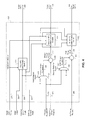
- FIG. 1 is a functional block diagram of an example engine system according to the present disclosure
- FIG. 2 is a functional block diagram of an example engine control system according to the present disclosure
- FIG. 3 is a functional block diagram of an example air control module according to the present disclosure.
- FIG. 4 is a functional block diagram of an example target air per cylinder (APC) module according to the present disclosure.
- FIG. 5 includes a flowchart depicting an example method of controlling a throttle valve, intake and exhaust valve phasing, a wastegate, and an exhaust gas recirculation (EGR) valve, according to the present disclosure.
- EGR exhaust gas recirculation
- An engine control module controls torque output of an engine. More specifically, the ECM controls actuators of the engine based on target values, respectively, to produce a requested amount of torque. For example, the ECM controls intake and exhaust valve phasing based on target intake and exhaust phasing angles, a throttle valve based on a target throttle opening, an exhaust gas recirculation (EGR) valve based on a target EGR opening, and a wastegate of a turbocharger based on a target wastegate duty cycle.
- ECM engine control module
- the ECM determines a torque request for controlling intake and exhaust cam phasing, the throttle valve, the EGR valve, and the wastegate.
- the ECM shapes the torque request into a shaped torque request.
- the ECM determines a first target torque based on the shaped torque request and a first torque adjustment and determines the target throttle opening and the target wastegate duty cycle based on the first target torque.
- the ECM also determines a second target torque based on the shaped torque request and a second torque adjustment and determines the target intake and exhaust phasing angles based on the second target torque.
- the ECM determines a third target torque based on the (non-shaped) torque request and a third torque adjustment and determines the target EGR opening based on the third target torque.
- setting of the first target torque, the second target torque, and the third target torque is coordinated with the response characteristics of the throttle valve 112 and the turbocharger, the intake and exhaust cam phasers 148 and 150 , and the EGR valve 170 , respectively.
- the coordination of the target torques with the respective response characteristics may increase engine performance and response.
- the engine system 100 includes an engine 102 that combusts an air/fuel mixture to produce drive torque for a vehicle based on driver input from a driver input module 104 .
- Air is drawn into an intake manifold 110 through a throttle valve 112 .
- the throttle valve 112 may include a butterfly valve having a rotatable blade.
- An engine control module (ECM) 114 controls a throttle actuator module 116 , which regulates opening of the throttle valve 112 to control the amount of air drawn into the intake manifold 110 .
- ECM engine control module
- Air from the intake manifold 110 is drawn into cylinders of the engine 102 .
- the engine 102 may include multiple cylinders, for illustration purposes a single representative cylinder 118 is shown.
- the engine 102 may include 2, 3, 4, 5, 6, 8, 10, and/or 12 cylinders.
- the ECM 114 may instruct a cylinder actuator module 120 to selectively deactivate some of the cylinders, which may improve fuel economy under certain engine operating conditions.
- the engine 102 may operate using a four-stroke cycle.
- the four strokes described below, may be referred to as the intake stroke, the compression stroke, the combustion stroke, and the exhaust stroke.
- the intake stroke may be referred to as the intake stroke, the compression stroke, the combustion stroke, and the exhaust stroke.
- two of the four strokes occur within the cylinder 118 . Therefore, two crankshaft revolutions are necessary for the cylinder 118 to experience all four of the strokes.
- the ECM 114 controls a fuel actuator module 124 , which regulates fuel injection to achieve a target air/fuel ratio. Fuel may be injected into the intake manifold 110 at a central location or at multiple locations, such as near the intake valve 122 of each of the cylinders. In various implementations (not shown), fuel may be injected directly into the cylinders or into mixing chambers associated with the cylinders. The fuel actuator module 124 may halt injection of fuel to cylinders that are deactivated.
- the injected fuel mixes with air and creates an air/fuel mixture in the cylinder 118 .
- a piston within the cylinder 118 compresses the air/fuel mixture.
- the engine 102 may be a compression-ignition engine, in which case compression within the cylinder 118 ignites the air/fuel mixture.
- the engine 102 may be a spark-ignition engine, in which case a spark actuator module 126 energizes a spark plug 128 in the cylinder 118 based on a signal from the ECM 114 , which ignites the air/fuel mixture.
- the timing of the spark may be specified relative to the time when the piston is at its topmost position, referred to as top dead center (TDC).
- the spark actuator module 126 may be controlled by a timing signal specifying how far before or after TDC to generate the spark. Because piston position is directly related to crankshaft rotation, operation of the spark actuator module 126 may be synchronized with crankshaft angle. The spark actuator module 126 may halt provision of spark to deactivated cylinders. Generating spark may be referred to as a firing event. The spark actuator module 126 may have the ability to vary the timing of the spark for each firing event. The spark actuator module 126 may vary the spark timing for a next firing event when the spark timing is changed between a last firing event and the next firing event.
- the combustion of the air/fuel mixture drives the piston away from TDC, thereby driving the crankshaft.
- the combustion stroke may be defined as the time between the piston reaching TDC and the time at which the piston reaches bottom dead center (BDC).
- BDC bottom dead center
- the piston begins moving away from BDC and expels the byproducts of combustion through an exhaust valve 130 .
- the byproducts of combustion are exhausted from the vehicle via an exhaust system 134 .
- the intake valve 122 may be controlled by an intake camshaft 140
- the exhaust valve 130 may be controlled by an exhaust camshaft 142
- multiple intake camshafts may control multiple intake valves (including the intake valve 122 ) for the cylinder 118 and/or may control the intake valves (including the intake valve 122 ) of multiple banks of cylinders (including the cylinder 118 ).
- multiple exhaust camshafts may control multiple exhaust valves for the cylinder 118 and/or may control exhaust valves (including the exhaust valve 130 ) for multiple banks of cylinders (including the cylinder 118 ).
- the cylinder actuator module 120 may deactivate the cylinder 118 by disabling opening of the intake valve 122 and/or the exhaust valve 130 .
- the intake valve 122 and/or the exhaust valve 130 may be controlled by devices other than camshafts, such as camless valve actuators.
- the time when the intake valve 122 is opened may be varied with respect to piston TDC by an intake cam phaser 148 .
- the time when the exhaust valve 130 is opened may be varied with respect to piston TDC by an exhaust cam phaser 150 .
- a phaser actuator module 158 may control the intake cam phaser 148 and the exhaust cam phaser 150 based on signals from the ECM 114 .
- variable valve lift (not shown) may also be controlled by the phaser actuator module 158 .
- the engine system 100 may include a boost device that provides pressurized air to the intake manifold 110 .
- FIG. 1 shows a turbocharger including a hot turbine 160 - 1 that is powered by hot exhaust gases flowing through the exhaust system 134 .
- the turbocharger also includes a cold air compressor 160 - 2 that is driven by the turbine 160 - 1 .
- the compressor 160 - 2 compresses air leading into the throttle valve 112 .
- a supercharger (not shown), driven by the crankshaft, may compress air from the throttle valve 112 and deliver the compressed air to the intake manifold 110 .
- a wastegate 162 may allow exhaust to bypass the turbine 160 - 1 , thereby reducing the boost (the amount of intake air compression) provided by the turbocharger.
- the ECM 114 may control the turbocharger via a boost actuator module 164 .
- the boost actuator module 164 may modulate the boost of the turbocharger by controlling opening of the wastegate 162 .
- multiple turbochargers may be controlled by the boost actuator module 164 .
- the turbocharger may have variable geometry, which may be controlled by the boost actuator module 164 .
- An intercooler may dissipate some of the heat contained in the compressed air charge, which is generated as the air is compressed.
- the compressed air charge may also have absorbed heat from components of the exhaust system 134 .
- the turbine 160 - 1 and the compressor 160 - 2 may be attached to each other, placing intake air in close proximity to hot exhaust.
- the engine system 100 may include an exhaust gas recirculation (EGR) valve 170 , which selectively redirects exhaust gas back to the intake manifold 110 .
- the EGR valve 170 may be located upstream of the turbocharger's turbine 160 - 1 .
- the EGR valve 170 may be controlled by an EGR actuator module 172 .
- the engine system 100 may measure the speed of the crankshaft in revolutions per minute (RPM) using an RPM sensor 180 .
- the temperature of the engine coolant may be measured using an engine coolant temperature (ECT) sensor 182 .
- ECT engine coolant temperature
- the ECT sensor 182 may be located within the engine 102 or at other locations where the coolant is circulated, such as a radiator (not shown).
- the pressure within the intake manifold 110 may be measured using a manifold absolute pressure (MAP) sensor 184 .
- MAP manifold absolute pressure
- engine vacuum which is the difference between ambient air pressure and the pressure within the intake manifold 110 , may be measured.
- the mass flow rate of air flowing into the intake manifold 110 may be measured using a mass air flow (MAF) sensor 186 .
- the MAF sensor 186 may be located in a housing that also includes the throttle valve 112 .
- the throttle actuator module 116 may monitor the position of the throttle valve 112 using one or more throttle position sensors (TPS) 190 .
- TPS throttle position sensors
- IAT intake air temperature
- the engine system 100 may also include one or more other sensors.
- the ECM 114 may use signals from the sensors to make control decisions for the engine system 100 .
- the ECM 114 may communicate with a transmission control module 194 to coordinate shifting gears in a transmission (not shown). For example, the ECM 114 may reduce engine torque during a gear shift.
- the ECM 114 may communicate with a hybrid control module 196 to coordinate operation of the engine 102 and an electric motor 198 .
- the electric motor 198 may also function as a generator, and may be used to produce electrical energy for use by vehicle electrical systems and/or for storage in a battery.
- various functions of the ECM 114 , the transmission control module 194 , and the hybrid control module 196 may be integrated into one or more modules.
- Each system that varies an engine parameter may be referred to as an actuator.
- Each system receives a target actuator value.
- the throttle actuator module 116 may be referred to as an actuator, and a target throttle opening (e.g., area) may be referred to as the target actuator value.
- the throttle actuator module 116 achieves the target throttle opening by adjusting an angle of the blade of the throttle valve 112 .
- the spark actuator module 126 may be referred to as an actuator, while the corresponding target actuator value may be a target spark timing relative to piston TDC.
- Other actuators may include the cylinder actuator module 120 , the fuel actuator module 124 , the phaser actuator module 158 , the boost actuator module 164 , and the EGR actuator module 172 .
- the target actuator values may include target number of activated cylinders, target fueling parameters, target intake and exhaust cam phaser angles, target wastegate duty cycle, and target EGR valve opening area, respectively.
- the ECM 114 may generate the target actuator values to cause the engine 102 to generate a target engine output torque.
- An example implementation of the ECM 114 includes a driver torque module 202 , an axle torque arbitration module 204 , and a propulsion torque arbitration module 206 .
- the ECM 114 may include a hybrid optimization module 208 .
- the ECM 114 also includes a reserves/loads module 220 , a torque requesting module 224 , an air control module 228 , a spark control module 232 , a cylinder control module 236 , and a fuel control module 240 .
- the ECM 114 also includes an air per cylinder (APC) torque estimation module 244 , a MAP torque estimation module 246 , a boost control module 248 , a phaser control module 252 , and an EGR control module 253 .
- API air per cylinder
- the driver torque module 202 may determine a driver torque request 254 based on a driver input 255 from the driver input module 104 .
- the driver input 255 may be based on, for example, a position of an accelerator pedal and a position of a brake pedal.
- the driver input 255 may also be based on cruise control, which may be an adaptive cruise control system that varies vehicle speed to maintain a predetermined following distance.
- the driver torque module 202 may store one or more mappings of accelerator pedal position to target torque and may determine the driver torque request 254 based on a selected one of the mappings.
- An axle torque arbitration module 204 arbitrates between the driver torque request 254 and other axle torque requests 256 .
- Axle torque (torque at the wheels) may be produced by various sources including an engine and/or an electric motor.
- the axle torque requests 256 may include a torque reduction requested by a traction control system when positive wheel slip is detected. Positive wheel slip occurs when axle torque overcomes friction between the wheels and the road surface, and the wheels begin to slip against the road surface.
- the axle torque requests 256 may also include a torque increase request to counteract negative wheel slip, where a tire of the vehicle slips in the other direction with respect to the road surface because the axle torque is negative.
- the axle torque requests 256 may also include brake management requests and vehicle over-speed torque requests.
- Brake management requests may reduce axle torque to ensure that the axle torque does not exceed the ability of the brakes to hold the vehicle when the vehicle is stopped.
- Vehicle over-speed torque requests may reduce the axle torque to prevent the vehicle from exceeding a predetermined speed.
- the axle torque requests 256 may also be generated by vehicle stability control systems.
- the axle torque arbitration module 204 outputs a predicted torque request 257 and an immediate torque request 258 based on the results of arbitrating between the received torque requests 254 and 256 . As described below, the predicted and immediate torque requests 257 and 258 from the axle torque arbitration module 204 may selectively be adjusted by other modules of the ECM 114 before being used to control the actuators of the engine system 100 .
- the immediate torque request 258 is the amount of currently target axle torque
- the predicted torque request 257 is the amount of axle torque that may be needed on short notice.
- the ECM 114 controls the engine system 100 to produce an axle torque equal to the immediate torque request 258 .
- different combinations of actuator values may result in the same axle torque.
- the ECM 114 may therefore adjust the target actuator values to enable a faster transition to the predicted torque request 257 , while still maintaining the axle torque at the immediate torque request 258 .
- the predicted torque request 257 may be set based on the driver torque request 254 .
- the immediate torque request 258 may be set to less than the predicted torque request 257 under some circumstances, such as when the driver torque request 254 is causing wheel slip on an icy surface.
- a traction control system (not shown) may request a reduction via the immediate torque request 258 , and the ECM 114 reduces the engine torque output to the immediate torque request 258 .
- the ECM 114 performs the reduction so the engine system 100 can quickly resume producing the predicted torque request 257 once the wheel slip stops.
- the difference between the immediate torque request 258 and the (generally higher) predicted torque request 257 can be referred to as a torque reserve.
- the torque reserve may represent the amount of additional torque (above the immediate torque request 258 ) that the engine system 100 can begin to produce with minimal delay.
- Fast engine actuators are used to increase or decrease current axle torque with minimal delay. As described in more detail below, fast engine actuators are defined in contrast with slow engine actuators.
- fast engine actuators are capable of varying axle torque within a range, where the range is established by the slow engine actuators.
- the upper limit of the range is the predicted torque request 257
- the lower limit of the range is limited by the torque (varying) capacity of the fast actuators.
- fast actuators may only be able to reduce axle torque by a first amount, where the first amount is a measure of the torque capacity of the fast actuators. The first amount may vary based on engine operating conditions set by the slow engine actuators.
- fast engine actuators can be controlled to cause the axle torque to be equal to the immediate torque request 258 .
- the fast engine actuators can be controlled to vary the axle torque to the top of the range, which is the predicted torque request 257 .
- fast engine actuators can change the axle torque more quickly than slow engine actuators.
- Slow actuators may respond more slowly to changes in their respective actuator values than fast actuators do.
- a slow actuator may include mechanical components that require time to move from one position to another in response to a change in actuator value.
- a slow actuator may also be characterized by the amount of time it takes for the axle torque to begin to change once the slow actuator begins to implement the changed actuator value. Generally, this amount of time will be longer for slow actuators than for fast actuators.
- the axle torque may take longer to fully respond to a change in a slow actuator.
- the ECM 114 may set actuator values for slow actuators to values that would enable the engine system 100 to produce the predicted torque request 257 if the fast actuators were set to appropriate values. Meanwhile, the ECM 114 may set target actuator values for fast actuators to values that, given the slow actuator values, cause the engine system 100 to produce the immediate torque request 258 instead of the predicted torque request 257 .
- the fast actuators therefore cause the engine system 100 to produce the immediate torque request 258 .
- the ECM 114 decides to transition the axle torque from the immediate torque request 258 to the predicted torque request 257
- the ECM 114 changes the target actuator values for one or more fast actuators to values that correspond to the predicted torque request 257 .
- the target actuator values for the slow actuators have already been set based on the predicted torque request 257
- the engine system 100 is able to produce the predicted torque request 257 after only the (minimal) delay imposed by the fast actuators. In other words, the longer delay that would otherwise result from changing axle torque using slow actuators is avoided.
- spark timing may be a fast actuator value
- throttle opening may be a slow actuator value
- Spark-ignition engines may combust fuels including, for example, gasoline and ethanol, by applying a spark.
- fuel flow may be a fast actuator value
- throttle opening may be used as an actuator value for engine characteristics other than torque.
- Compression-ignition engines may combust fuels including, for example, diesel fuel, via compression.
- the spark actuator module 126 may be a fast actuator and the throttle actuator module 116 may be a slow actuator. After receiving a new target actuator value, the spark actuator module 126 may be able to change spark timing for the following firing event.
- spark timing also called spark advance
- a maximum amount of torque may be produced in the combustion stroke immediately following the firing event.
- a spark timing deviating from the optimum value may reduce the amount of torque produced in the combustion stroke. Therefore, the spark actuator module 126 may be able to vary engine output torque as soon as the next firing event occurs by varying spark timing.
- a table of optimum spark timings corresponding to different engine operating conditions may be determined during a calibration phase of vehicle design, and the optimum value is selected from the table based on current engine operating conditions.
- the throttle actuator module 116 changes the throttle opening by adjusting the angle of the blade of the throttle valve 112 . Therefore, once a new actuator value is received, there is a mechanical delay as the throttle valve 112 moves from its previous position to a new position based on the new target actuator value. In addition, air flow changes based on the throttle opening are subject to air transport delays in the intake manifold 110 . Further, increased air flow in the intake manifold 110 is not realized as an increase in engine output torque until the cylinder 118 receives additional air in the next intake stroke, compresses the additional air, and commences the combustion stroke.
- a torque reserve can be created by setting the throttle opening to a value that would allow the engine 102 to produce the predicted torque request 257 .
- the spark timing can be set based on the immediate torque request 258 , which is less than the predicted torque request 257 .
- the throttle opening generates enough air flow for the engine 102 to produce the predicted torque request 257
- the spark timing is retarded (which reduces torque) based on the immediate torque request 258 .
- the engine output torque will therefore be equal to the immediate torque request 258 .
- the spark timing can be set based on the predicted torque request 257 or a torque between the predicted and immediate torque requests 257 and 258 .
- the spark actuator module 126 may return the spark timing to an optimum value, which allows the engine 102 to produce the full engine output torque achievable with the air flow already present. The engine output torque may therefore be quickly increased to the predicted torque request 257 without experiencing delays from changing the throttle opening.
- the axle torque arbitration module 204 may output the predicted torque request 257 and the immediate torque request 258 to a propulsion torque arbitration module 206 .
- the axle torque arbitration module 204 may output the predicted and immediate torque requests 257 and 258 to the hybrid optimization module 208 .
- the hybrid optimization module 208 may determine how much torque should be produced by the engine 102 and how much torque should be produced by the electric motor 198 .
- the hybrid optimization module 208 then outputs modified predicted and immediate torque requests 259 and 260 , respectively, to the propulsion torque arbitration module 206 .
- the hybrid optimization module 208 may be implemented in the hybrid control module 196 .
- the predicted and immediate torque requests received by the propulsion torque arbitration module 206 are converted from an axle torque domain (torque at the wheels) into a propulsion torque domain (torque at the crankshaft). This conversion may occur before, after, as part of, or in place of the hybrid optimization module 208 .
- the propulsion torque arbitration module 206 arbitrates between propulsion torque requests 290 , including the converted predicted and immediate torque requests.
- the propulsion torque arbitration module 206 generates an arbitrated predicted torque request 261 and an arbitrated immediate torque request 262 .
- the arbitrated torque requests 261 and 262 may be generated by selecting a winning request from among received torque requests. Alternatively or additionally, the arbitrated torque requests may be generated by modifying one of the received requests based on another one or more of the received torque requests.
- the propulsion torque requests 290 may include torque reductions for engine over-speed protection, torque increases for stall prevention, and torque reductions requested by the transmission control module 194 to accommodate gear shifts.
- the propulsion torque requests 290 may also result from clutch fuel cutoff, which reduces the engine output torque when the driver depresses the clutch pedal in a manual transmission vehicle to prevent a flare (rapid rise) in engine speed.
- the propulsion torque requests 290 may also include an engine shutoff request, which may be initiated when a critical fault is detected.
- critical faults may include detection of vehicle theft, a stuck starter motor, electronic throttle control problems, and unexpected torque increases.
- arbitration selects the engine shutoff request as the winning request.
- the propulsion torque arbitration module 206 may output zero as the arbitrated predicted and immediate torque requests 261 and 262 .
- an engine shutoff request may simply shut down the engine 102 separately from the arbitration process.
- the propulsion torque arbitration module 206 may still receive the engine shutoff request so that, for example, appropriate data can be fed back to other torque requestors. For example, all other torque requestors may be informed that they have lost arbitration.
- the reserves/loads module 220 receives the arbitrated predicted and immediate torque requests 261 and 262 .
- the reserves/loads module 220 may adjust the arbitrated predicted and immediate torque requests 261 and 262 to create a torque reserve and/or to compensate for one or more loads.
- the reserves/loads module 220 then outputs adjusted predicted and immediate torque requests 263 and 264 to the torque requesting module 224 .
- a catalyst light-off process or a cold start emissions reduction process may require retarded spark timing.
- the reserves/loads module 220 may therefore increase the adjusted predicted torque request 263 above the adjusted immediate torque request 264 to create retarded spark for the cold start emissions reduction process.
- the air/fuel ratio of the engine and/or the mass air flow may be directly varied, such as by diagnostic intrusive equivalence ratio testing and/or new engine purging. Before beginning these processes, a torque reserve may be created or increased to quickly offset decreases in engine output torque that result from leaning the air/fuel mixture during these processes.
- the reserves/loads module 220 may also create or increase a torque reserve in anticipation of a future load, such as power steering pump operation or engagement of an air conditioning (NC) compressor clutch.
- the reserve for engagement of the NC compressor clutch may be created when the driver first requests air conditioning.
- the reserves/loads module 220 may increase the adjusted predicted torque request 263 while leaving the adjusted immediate torque request 264 unchanged to produce the torque reserve. Then, when the NC compressor clutch engages, the reserves/loads module 220 may increase the adjusted immediate torque request 264 by the estimated load of the A/C compressor clutch.
- the torque requesting module 224 receives the adjusted predicted and immediate torque requests 263 and 264 .
- the torque requesting module 224 determines how the adjusted predicted and immediate torque requests 263 and 264 will be achieved.
- the torque requesting module 224 may be engine type specific.
- the torque requesting module 224 may be implemented differently or use different control schemes for spark-ignition engines versus compression-ignition engines.
- the torque requesting module 224 may define a boundary between modules that are common across all engine types and modules that are engine type specific.
- engine types may include spark-ignition and compression-ignition.
- Modules prior to the torque requesting module 224 such as the propulsion torque arbitration module 206 , may be common across engine types, while the torque requesting module 224 and subsequent modules may be engine type specific.
- the torque requesting module 224 may vary the opening of the throttle valve 112 as a slow actuator that allows for a wide range of torque control.
- the torque requesting module 224 may disable cylinders using the cylinder actuator module 120 , which also provides for a wide range of torque control, but may also be slow and may involve drivability and emissions concerns.
- the torque requesting module 224 may use spark timing as a fast actuator. However, spark timing may not provide as much range of torque control.
- spark reserve capacity may vary as air flow changes.
- the torque requesting module 224 may generate an air torque request 265 based on the adjusted predicted torque request 263 .
- the air torque request 265 may be equal to the adjusted predicted torque request 263 , setting air flow so that the adjusted predicted torque request 263 can be achieved by changes to other (e.g., fast) actuators.
- Target actuator values for airflow controlling actuators may be determined based on the air torque request 265 .
- the air control module 228 may determine a target manifold absolute pressure (MAP) 266 , a target throttle opening (e.g., area) 267 , a second target air per cylinder (APC2) 268 , and a third target APC (APC3) 291 based on the air torque request 265 . Determination of the second and third target APCs 268 and 291 are discussed further below.
- the boost control module 248 may determine a target duty cycle 269 for the wastegate 162 based on the target MAP 266 . While the target duty cycle 269 will be discussed, the boost control module 248 may determine another suitable value for controlling the wastegate 162 .
- the phaser control module 252 may determine target intake and exhaust cam phaser angles 270 and 271 based on the second target APC 268 .
- the EGR control module 253 determines a target EGR opening 292 based on the third target APC 291 .
- the torque requesting module 224 may also generate a spark torque request 272 , a cylinder shut-off torque request 273 , and a fuel torque request 274 .
- the spark control module 232 may determine how much to retard the spark timing (which reduces engine output torque) from an optimum spark timing based on the spark torque request 272 .
- a torque relationship may be inverted to solve for a desired spark timing 299 .
- the air/fuel ratio (AF) may be the actual air/fuel ratio, as reported by the fuel control module 240 .
- the spark control module 232 may also generate a target spark timing 275 , as discussed further below in conjunction with FIG. 3 .
- the resulting torque may be as close to a maximum best torque (MBT) as possible.
- MBT refers to the maximum engine output torque that is generated for a given air flow as spark timing is advanced, while using fuel having an octane rating greater than a predetermined octane rating and using stoichiometric fueling.
- the spark timing at which this maximum torque occurs is referred to as an MBT spark timing.
- the optimum spark timing may differ slightly from MBT spark timing because of, for example, fuel quality (such as when lower octane fuel is used) and environmental factors. The engine output torque at the optimum spark timing may therefore be less than MBT.
- the cylinder shut-off torque request 273 may be used by the cylinder control module 236 to determine a target number of cylinders to deactivate 276 .
- the cylinder control module 236 may also instruct the fuel control module 240 to stop providing fuel for deactivated cylinders and may instruct the spark control module 232 to stop providing spark for deactivated cylinders.
- the spark control module 232 may stop providing spark to a cylinder once an fuel/air mixture that is already present in the cylinder has been combusted.
- the fuel control module 240 may vary the amount of fuel provided to each cylinder based on the fuel torque request 274 . More specifically, the fuel control module 240 may generate target fueling parameters 277 based on the fuel torque request 274 .
- the target fueling parameters 277 may include, for example, target mass of fuel, target injection starting timing, and target number of fuel injections.
- the fuel control module 240 may operate in an air lead mode in which the fuel control module 240 attempts to maintain a stoichiometric air/fuel ratio by controlling fueling based on air flow.
- the fuel control module 240 may determine a target fuel mass that will yield stoichiometric combustion when combined with a present mass of air per cylinder (APC).
- the fuel control module 240 may operate in a fuel lead mode in which the fuel control module 240 determines a target fuel mass for each cylinder that satisfies the fuel torque request 274 while minimizing emissions, noise, and fuel consumption.
- air flow is controlled based on fuel flow and may be controlled to yield a lean air/fuel ratio.
- the air/fuel ratio may be maintained above a predetermined level, which may prevent black smoke production in dynamic engine operating conditions.
- the air control module 228 generates the target MAP 266 further based on a MAP estimated torque 278 .
- the MAP estimated torque 278 corresponds to an estimated value of the present engine torque output determined based on a MAP 279 measured using the MAP sensor 184 .
- the MAP torque estimation module 246 generates the MAP estimated torque 278 based on the MAP 279 and other measured engine operating parameters.
- the relationship may be embodied as an equation or as a look-up table.
- the phaser control module 252 may provide the measured intake and exhaust cam phaser angles 281 and 282 .
- the phaser control module 252 may generate the measured intake and exhaust cam phaser angles 281 and 282 based on previous values of the measured intake and exhaust cam phaser angles 281 and 282 and the target intake and exhaust cam phaser angles 270 and 271 .
- the air control module 228 generates various target values further based on a first APC estimated torque 283 .
- the first APC estimated torque 283 corresponds to an estimated value of the present engine torque output determined based on a present APC 284 .
- the present APC 284 is determined based on one or more measured parameters, such as the MAF, the MAP, and/or the IAT.
- the APC torque estimation module 244 generates the first APC estimated torque 283 based on the present APC 284 and other measured engine operating parameters.
- the relationship may be embodied as an equation or as a look-up table.
- the APC torque estimation module 244 also generates a second APC estimated torque 298 based on the present APC 284 and the target intake and exhaust cam phaser angles 270 and 271 .
- the relationship may be embodied as an equation or as a look-up table.
- the air control module 228 may output the target throttle opening 267 to the throttle actuator module 116 .
- the throttle actuator module 116 regulates the throttle valve 112 to produce the target throttle opening 267 .
- the air control module 228 outputs the target MAP 266 to the boost control module 248 .
- the boost control module 248 controls the wastegate 162 based on the target MAP 266 .
- the air control module 228 outputs the second target APC 268 to the phaser control module 252 . Based on the second target APC 268 and the engine speed (and/or crankshaft position), the phaser control module 252 may control positions of the intake and/or exhaust cam phasers 148 and 150 .
- a delay and rate limit module 302 applies one or more shaping actions to the air torque request 265 to produce a shaped air torque request 303 . More specifically, the delay and rate limit module 302 stores the air torque request 265 for a delay period before outputting the stored air torque request as a delayed air torque request (not shown). The delay and rate limit module 302 may determine the delay period based on an EGR value (e.g., opening or mass flow rate) and/or the engine speed (RPM). The delay and rate limit module 302 applies a rate limit to the delayed air torque request to produce the shaped air torque request 303 .
- EGR value e.g., opening or mass flow rate
- RPM engine speed
- the delay and rate limit module 302 adjusts the shaped air torque request 303 toward the delayed air torque request by up to a maximum amount per predetermined period.
- the delay and rate limit module 302 may determine the maximum amount based on the EGR value and/or the engine speed. While delaying and rate limiting shaping actions have been described, one or more other shaping actions may also be performed.
- a torque error module 304 determines a torque error 308 based on a difference between the shaped air torque request 303 and the first APC estimated torque 283 .
- the torque error module 304 may set the torque error 308 equal to the air torque request 265 minus the first APC estimated torque 283 .
- An adjustment module 312 generates a torque adjustment 316 based on the torque error 308 .
- the torque adjustment 316 is equal to the sum of the P torque adjustment and the I torque adjustment 318 .
- another suitable type of closed-loop controller may be used to generate the torque adjustment 316 based on the torque error 308 .
- a target determination module 320 determines a target torque 324 based on the shaped air torque request 303 and the torque adjustment 316 . For example, the target determination module 320 may set the target torque 324 equal to the shaped air torque request 303 plus the torque adjustment 316 .
- a target APC module 328 generates a first target APC (APC1) 329 .
- FIG. 4 is a functional block diagram of an example implementation of the target APC module 328 .
- a first APC determination module 404 determines the first target APC 329 based on the target torque 324 , the target spark timing 275 , and selected intake and exhaust cam phaser angles 330 and 331 .
- the first APC determination module 404 determines the first target APC 329 further based on the engine speed, the present air/fuel ratio, the oil temperature, and the present number of active cylinders. Relationship (4) provided above may be inverted and solved to determine the first target APC 329 .
- the target intake and exhaust cam phaser angles 270 and 271 may be used in place of the selected intake and exhaust cam phaser angles 330 and 331 .
- This relationship may be embodied as an equation or as a look-up table. Generation of the selected intake and exhaust cam phaser angles 330 and 331 is discussed further below.
- the target APC module 328 also generates the second and third target APCs 268 and 291 .
- a second APC determination module 408 determines the second target APC 268 based on a phaser target torque 412 , the target spark timing 275 , and selected intake and exhaust cam phaser angles 330 and 331 .
- the second APC determination module 408 determines the second target APC 268 further based on the engine speed, the present air/fuel ratio, the oil temperature, and the present number of active cylinders. Relationship (4) provided above may be inverted and solved to determine the second target APC 268 .
- the target intake and exhaust cam phaser angles 270 and 271 may be used in place of the selected intake and exhaust cam phaser angles 330
- a target phaser torque module 416 determines the phaser target torque 412 based on the shaped air torque request 303 and a phaser torque adjustment 420 . For example, the target phaser torque module 416 may set the phaser target torque 412 equal to the phaser torque adjustment 420 plus the shaped air torque request 303 .
- a first selection module 424 sets the phaser torque adjustment 420 to one of zero and the I torque adjustment 318 based on a first selection signal 428 .
- the first selection module 424 may set the phaser torque adjustment 420 to zero when the first selection signal 428 is in a first state and set the phaser torque adjustment 420 to the I torque adjustment 318 when the first selection signal 428 is in a second state.
- the state of the first selection signal 428 may be set, for example, during the calibration stage of vehicle design.
- the first selection signal 428 may be set to the first state when the phaser control module 252 can change the target intake and/or exhaust phaser angles 270 and 271 at greater than a predetermined rate.
- the first selection signal 428 may be set to the second state when the phaser control module 252 is limited to changing the target intake and/or exhaust phaser angles 270 and 271 at less than the predetermined rate.
- the phaser control module 252 ( FIG. 2 ) generates the target intake and exhaust cam phaser angles 270 and 271 based on the second target APC 268 .
- the phaser control module 252 may determine the target intake and exhaust cam phaser angles 270 and 271 based on the second target APC 268 and the engine speed.
- These relationships may be embodied as equations or as look-up tables.
- the phaser actuator module 158 controls the intake and exhaust cam phasers 148 and 150 based on the target intake and exhaust cam phaser angles 270 and 271 , respectively.
- a third APC determination module 432 determines the third target APC 291 based on an EGR target torque 436 , the target spark timing 275 , and selected intake and exhaust cam phaser angles 330 and 331 .
- the third APC determination module 432 determines the third target APC 291 further based on the engine speed, the present air/fuel ratio, the oil temperature, and the present number of active cylinders. Relationship (4) provided above may be inverted and solved to determine the third target APC 291 .
- the target intake and exhaust cam phaser angles 270 and 271 may be used in place of the selected intake and exhaust cam phaser
- a target EGR torque module 440 determines the EGR target torque 436 based on the air torque request 265 and an EGR torque adjustment 444 .
- the target EGR torque module 440 may set the EGR target torque 436 equal to the EGR torque adjustment 444 plus the air torque request 265 .
- a second selection module 448 sets the EGR torque adjustment 444 to one of zero and the I torque adjustment 318 based on a second selection signal 452 .
- the second selection module 448 may set the EGR torque adjustment 444 to zero when the second selection signal 452 is in a first state and set the EGR torque adjustment 444 to the I torque adjustment 318 when the second selection signal 452 is in a second state.
- the state of the second selection signal 452 may be set, for example, during the calibration stage of vehicle design.
- the second selection signal 452 may be set to the first state when the EGR control module 253 can change the target EGR opening 292 at greater than a predetermined rate.
- the second selection signal 452 may be set to the second state when the EGR control module 253 is limited to changing the target EGR opening 292 at less than the predetermined rate.
- the EGR control module 253 ( FIG. 2 ) generates the target EGR opening 292 based on the third target APC 291 .
- the EGR control module 253 may determine a target EGR mass flow rate based on the third target APC 291 and the engine speed.
- This relationship may be embodied as an equation or as a look-up table.
- the EGR control module 253 may determine the target EGR opening 292 based on the target EGR mass flow rate. The EGR control module 253 determines the target EGR opening 292 further based on the target MAP 266 , an exhaust temperature, and an exhaust pressure. For example, the EGR control module 253 may determine the target EGR opening 292 using the relationship:
- AREA EGRT M EGRT * R GAS * T exh P exh * ⁇ ⁇ ( MAP T P exh ) , ( 13 )
- AREA EGRT is the target EGR opening 292
- M EGRT is the target EGR mass flow rate
- MAP T is the target MAP 266
- R GAS is the ideal gas constant
- T exh is an exhaust temperature
- P exh is an exhaust pressure
- ⁇ represents an air density function.
- the EGR actuator module 172 controls the EGR valve 170 based on the target EGR opening 292 .
- a target MAP module 332 generates the target MAP 266 based on the target torque 324 , the target spark timing 275 , and the selected intake and exhaust cam phaser angles 330 and 331 .
- the target MAP module 332 generates the target MAP 266 further based on the engine speed, the present air/fuel ratio, the oil temperature, the present number of active cylinders, and an estimated torque difference 336 . Relationship (1) provided above may be inverted and solved to determine the target MAP 266 .
- the target intake and exhaust cam phaser angles 270 and 271 may be used in place of the selected intake and exhaust cam phaser angles 330 and 331 .
- This relationship may be embodied as an equation or as a look-up table. As noted above, generation of the selected intake and exhaust cam phaser angles 330 and 331 is discussed further below.
- a difference module 340 determines the estimated torque difference 336 .
- the difference module 340 determines the estimated torque difference 336 based on a difference between the MAP estimated torque 278 and the first APC estimated torque 283 .
- the difference module 340 may also apply a filter to the difference between the MAP estimated torque 278 and the first APC estimated torque 283 , such as a low pass filter, and output the filtered difference as the estimated torque difference 336 .
- the boost control module 248 may generate the target duty cycle 269 based on the target MAP 266 .
- the boost actuator module 164 controls the wastegate 162 (and therefore the turbocharger) based on the target duty cycle 269 .
- a target MAF module 344 generates a target MAF 348 into the engine 102 based on the first target APC 329 .
- the target MAF module 344 generates the target MAF 348 further based on the engine speed and the total number of cylinders of the engine 102 .
- the target MAF module 344 may generate the target MAF 348 using the relationship:
- MAF T APC T_ ⁇ 1 * RPM k CYL , ( 15 )
- MAF T is the target MAF 348
- APC T _ 1 is the first target APC 329
- RPM is the engine speed
- k CYL is a predetermined value set based on the total number of cylinders of the engine 102 .
- k CYL may be approximately 15 for an 8-cylinder engine and approximately 30 for a 4-cylinder engine.
- a throttle control module 352 determines the target throttle opening 267 for the throttle valve 112 based on the target MAF 348 .
- the throttle control module 352 determines the target throttle opening 267 further based on the target MAP 266 , an air temperature, and a barometric pressure.
- the throttle control module 352 may determine the target throttle opening 267 using the relationship:
- AREA T MAF T * R GAS * T B * ⁇ ⁇ ( MAP T B ) , ( 16 ) where AREA T is the target throttle opening 267 , MAF T is the target MAF 348 , MAP T is the target MAP 266 , R GAS is the ideal gas constant, T is the air temperature (e.g., ambient or intake), B is the barometric pressure, and ⁇ represents an air density function.
- the throttle actuator module 116 controls the throttle valve 112 based on the target throttle opening 267 .
- the throttle valve 112 and the turbocharger are controlled based on the target torque 324 , which is generated based on the shaped air torque request 303 and the torque adjustment 316 .
- the intake and exhaust cam phasers 148 and 150 are controlled based on the phaser target torque 412 , which is generated based on the shaped air torque request 303 and the phaser target torque 412 .
- the EGR valve 170 will be controlled based on the air torque request 265 and the EGR target torque 436 .
- This coordination may provide a steady-state and transient performance improvement.
- This relationship may be embodied as an
- a selecting module 356 sets the selected intake and exhaust cam phaser angles 330 and 331 based on either the measured intake and exhaust cam phaser angles 281 and 282 or the target intake and exhaust cam phaser angles 270 and 271 , respectively. More specifically, the selecting module 356 sets the selected intake cam phaser angle 330 based on either the measured intake cam phaser angle 281 or the target intake cam phaser angle 270 and sets the selected exhaust cam phaser angle 331 based on either the measured exhaust cam phaser angle 282 or the target exhaust cam phaser angle 271 .
- a selection signal 360 controls whether the selecting module 356 sets the selected intake and exhaust cam phaser angles 330 and 331 based on the measured intake and exhaust cam phaser angles 281 and 282 or based on the target intake and exhaust cam phaser angles 270 and 271 .
- the selecting module 356 may set the selected intake and exhaust cam phaser angles 330 and 331 based on the target intake and exhaust cam phaser angles 270 and 271 when the selection signal 360 is in a first state.
- the selecting module 356 may set the selected intake and exhaust cam phaser angles 330 and 331 based on the measured intake and exhaust cam phaser angles 281 and 282 .
- the selecting module 356 may rate limit changes in the selected intake and exhaust cam phaser angles 330 and 331 . For example, when the selection signal 360 transitions from the first state to the second state, the selecting module 356 may adjust the selected intake and exhaust cam phaser angles 330 and 331 toward the measured intake and exhaust cam phaser angles 281 and 282 by up to a first predetermined amount every predetermined period. When the selection signal 360 transitions from the second state to the first state, the selecting module 356 may adjust the selected intake and exhaust cam phaser angles 330 and 331 toward the target intake and exhaust cam phaser angles 270 and 271 by up to a second predetermined amount every predetermined period. The first and second predetermined amounts may be the same or different.
- a selection generation module 364 generates the selection signal 360 .
- the selection generation module 364 sums an APC torque difference 365 over a predetermined period (or a predetermined number of samples) to determine a cumulative difference.
- a second difference module 366 determines the APC torque difference 365 .
- the second difference module 366 determines the APC torque difference 365 based on a difference between the first APC estimated torque 283 and the second APC estimated torque 298 .
- the second difference module 366 may also apply a filter to the difference between the first APC estimated torque 283 and the second APC estimated torque 298 , such as a low pass filter, and output the filtered difference as the APC torque difference 365 .
- the selection generation module 364 generates the selection signal 360 based on the cumulative difference. More specifically, the selection generation module 364 sets the selection signal 360 to the first state when the cumulative difference is less than a predetermined value. When the cumulative difference is greater than the predetermined value, the selection generation module 364 may set the selection signal 360 to the second state. In this manner the selecting module 356 sets the selected intake and exhaust cam phaser angles 330 and 331 based on the target intake and exhaust cam phaser angles 270 and 271 when the cumulative difference is less than the predetermined value. When the cumulative difference is greater than the predetermined value, the selecting module 356 may set the selected intake and exhaust cam phaser angles 330 and 331 based on the measured intake and exhaust cam phaser angles 281 and 282 . This may ensure that use of the target intake and exhaust cam phaser angles 270 and 271 is limited to times when the target intake and exhaust cam phaser angles 270 and 271 are accurate, as indicated by the cumulative difference being less than the predetermined value.
- Control may begin with 504 where the torque requesting module 224 generates the air torque request 265 .
- the delay and rate limit module 302 updates the shaped air torque request 303 at 508 .
- the delay and rate limit module 302 receives the air torque request 265 and stores the air torque request 265 for the delay period.
- the delay and rate limit module 302 adjusts the shaped air torque request 303 toward a stored air torque request by up to the predetermined amount.
- the delay period and the predetermined amount may be determined based on the EGR value and/or the engine speed.
- the torque error module 304 generates the torque error 308 at 512 .
- the torque error module 304 determines the torque error 308 based on a difference between the shaped air torque request 303 and the first APC estimated torque 283 .
- the adjustment module 312 determines the P torque adjustment, the I torque adjustment 318 , and the torque adjustment 316 at 516 based on the torque error 308 .
- the adjustment module 312 may determine the P torque adjustment based on a product of the proportional gain (K P ) and the torque error 308 and determine the I torque adjustment 318 based on a product of the torque error 308 and an integral gain (K I ).
- the adjustment module 312 may set the torque adjustment 316 equal to the I torque adjustment 318 plus the P torque adjustment.
- the target determination module 320 generates the target torque 324
- the target phaser torque module 416 generates the phaser target torque 412
- the target EGR torque module 440 generates the EGR target torque 436 .
- the target determination module 320 determines the target torque 324 based on the torque adjustment 316 and the shaped air torque request 303 , as discussed above.
- the target phaser torque module 416 determines the phaser target torque 412 based on the shaped air torque request 303 and the phaser torque adjustment 420 , as discussed above.
- the target EGR torque module 440 determines the EGR torque target 436 based on the air torque request 265 and the EGR torque adjustment 444 , as described above.
- the first APC determination module 404 determines the first target APC 329
- the second APC determination module 408 determines the second target APC 268
- the third APC determination module 432 determines the third target APC 291 .
- the first APC determination module 404 determines the first target APC 329 based on the target torque 324 , as discussed above.
- the second APC determination module 408 determines the second target APC 268 based on the phaser target torque 412 , as discussed above.
- the third APC determination module 432 determines the third target APC 291 based on the EGR target torque 436 , as described above.
- the target MAF module 344 generates the target MAF 348
- the throttle control module 352 generates the target throttle opening 267
- the target MAP module 332 generates the target MAP 266 .
- the target MAF module 344 determines the target MAF 348 based on the first target APC 329 , as discussed above.
- the throttle control module 352 determines the target throttle opening 267 based on the target MAF 348 , as discussed above.
- the target MAP module 332 determines the target MAP 266 based on the target torque 324 , as discussed above.
- the boost control module 248 generates the target duty cycle 269
- the phaser control module 252 generates the target intake and exhaust cam phaser angles 270 and 271
- the EGR control module 253 generates the target EGR opening 292 .
- the boost control module 248 determines the target duty cycle 269 based on the target MAP 266 , as discussed above.
- the phaser control module 252 determines the target intake and exhaust cam phaser angles 270 and 271 based on the second target APC 268 , as discussed above.
- the EGR control module 253 determines the target EGR opening 292 based on the third target APC 291 , as discussed above.
- the throttle actuator module 116 selectively adjusts the throttle valve 112 based on the target throttle opening 267
- the boost actuator module 164 selectively adjusts the duty cycle applied to the wastegate 162 based on the target duty cycle 269 .
- the phaser actuator module 158 selectively adjusts the intake and exhaust cam phasers 148 and 150 based on the target intake and exhaust cam phaser angles 270 and 271
- the EGR actuator module 172 selectively adjusts the EGR valve 170 based on the target EGR opening 292 . Control may then end. While control is shown and discussed as ending, FIG. 5 may be illustrative of one control loop, and control loops may be executed at a predetermined rate.
- module may refer to, be part of, or include an Application Specific Integrated Circuit (ASIC); a discrete circuit; an integrated circuit; a combinational logic circuit; a field programmable gate array (FPGA); a processor (shared, dedicated, or group) that executes code; other suitable hardware components that provide the described functionality; or a combination of some or all of the above, such as in a system-on-chip.
- ASIC Application Specific Integrated Circuit
- FPGA field programmable gate array
- the term module may include memory (shared, dedicated, or group) that stores code executed by the processor.
- code may include software, firmware, and/or microcode, and may refer to programs, routines, functions, classes, and/or objects.
- shared means that some or all code from multiple modules may be executed using a single (shared) processor. In addition, some or all code from multiple modules may be stored by a single (shared) memory.
- group means that some or all code from a single module may be executed using a group of processors. In addition, some or all code from a single module may be stored using a group of memories.
- the apparatuses and methods described herein may be partially or fully implemented by one or more computer programs executed by one or more processors.
- the computer programs include processor-executable instructions that are stored on at least one non-transitory tangible computer readable medium.
- the computer programs may also include and/or rely on stored data.
- Non-limiting examples of the non-transitory tangible computer readable medium include nonvolatile memory, volatile memory, magnetic storage, and optical storage.
Abstract
Description
S des =f −1(T des ,APC,I,E,AF,OT,#). (0)
This relationship may be embodied as an equation and/or as a lookup table. The air/fuel ratio (AF) may be the actual air/fuel ratio, as reported by the
T MAP =f(MAP,RPM,S M ,I M ,E M ,AF,OT,#), (1)
where TMAP is the MAP estimated
I M =f(I T)+k*(I T −I M _ PREV), and (2)
E M =f(E T)+k*(E T −E M _ PREV), (3)
where IM is the measured intake
T APC1 =f(APC M ,RPM,S M ,I M ,E M ,AF,OT,#) (4)
where TAPC1 is the first APC estimated
T APC2 =f(APC M ,RPM,S M ,I T ,E T ,AF,OT,#), (5)
where TAPC2 is the second APC estimated
T ADJ =K P*(T ERROR)+K I *∫T ERROR ∂t, (6)
where TADJ is the
APC T _ 1 =T −1(T T ,RPM,S T ,I SEL ,E SEL ,AF,OT,#), (7)
where APCT _ 1 is the
APC T _ 2 =T −1(T PTT ,RPM,S T ,I SEL ,E SEL ,AF,OT,#), (8)
where APCT _ 2 is the
I T =f(RPM,APC T _ 2); and (9)
E T =f(RPM,APC T _ 2), (10)
where IT is the target intake
APC T _ 3 =T −1(T EGRT ,RPM,S T ,I SEL ,E SEL ,AF,OT,#) (11)
where APCT _ 3 is the
M EGRT =f(RPM,APC T _ 3) (12)
where MEGRT is the mass EGR flow rate, RPM is the engine speed, and APCT _ 3 is the
where AREAEGRT is the
MAP T =T −1((T T +f(T EST _ DIFF)),RPM,S T ,I SEL ,E SEL ,AF,OT,#) (14)
where MAPT is the target MAP266, TT is the
where MAFT is the
where AREAT is the
APC SPARK =T −1(T SPARK ,RPM,S M ,I T ,E T ,AF,OT,#) (17)
where APCSPARK is the spark APC, TSPARK is the
S T =f(APC SPARK ,RPM), (18)
where ST is the
Claims (18)
Priority Applications (4)
| Application Number | Priority Date | Filing Date | Title |
|---|---|---|---|
| US13/686,069 US9534547B2 (en) | 2012-09-13 | 2012-11-27 | Airflow control systems and methods |
| DE102013218374.7A DE102013218374B4 (en) | 2012-09-18 | 2013-09-13 | METHOD FOR CONTROLLING AIR FLOW |
| CN201310428204.0A CN103670762B (en) | 2012-09-18 | 2013-09-18 | air flow control system and method |
| US14/931,134 US9863345B2 (en) | 2012-11-27 | 2015-11-03 | System and method for adjusting weighting values assigned to errors in target actuator values of an engine when controlling the engine using model predictive control |
Applications Claiming Priority (4)
| Application Number | Priority Date | Filing Date | Title |
|---|---|---|---|
| US13/613,588 US9175628B2 (en) | 2012-09-13 | 2012-09-13 | Coordinated engine torque control |
| US13/613,683 US8954257B2 (en) | 2012-09-13 | 2012-09-13 | Coordinated torque control security systems and methods |
| US201261702430P | 2012-09-18 | 2012-09-18 | |
| US13/686,069 US9534547B2 (en) | 2012-09-13 | 2012-11-27 | Airflow control systems and methods |
Publications (2)
| Publication Number | Publication Date |
|---|---|
| US20140076279A1 US20140076279A1 (en) | 2014-03-20 |
| US9534547B2 true US9534547B2 (en) | 2017-01-03 |
Family
ID=50273151
Family Applications (1)
| Application Number | Title | Priority Date | Filing Date |
|---|---|---|---|
| US13/686,069 Active 2035-09-28 US9534547B2 (en) | 2012-09-13 | 2012-11-27 | Airflow control systems and methods |
Country Status (2)
| Country | Link |
|---|---|
| US (1) | US9534547B2 (en) |
| CN (1) | CN103670762B (en) |
Cited By (11)
| Publication number | Priority date | Publication date | Assignee | Title |
|---|---|---|---|---|
| US20160017813A1 (en) * | 2013-03-15 | 2016-01-21 | United Technologies Corporation | Compact Aero-Thermo Model Based Degraded Mode Control |
| US20180216563A1 (en) * | 2017-02-01 | 2018-08-02 | GM Global Technology Operations LLC | Method to determine reference airflow actuator positions for a gasoline engine |
| US10358140B2 (en) | 2017-09-29 | 2019-07-23 | GM Global Technology Operations LLC | Linearized model based powertrain MPC |
| US10399574B2 (en) | 2017-09-07 | 2019-09-03 | GM Global Technology Operations LLC | Fuel economy optimization using air-per-cylinder (APC) in MPC-based powertrain control |
| US20190344773A1 (en) * | 2018-05-11 | 2019-11-14 | Toyota Jidosha Kabushiki Kaisha | Control system for hybrid vehicle |
| US10619586B2 (en) | 2018-03-27 | 2020-04-14 | GM Global Technology Operations LLC | Consolidation of constraints in model predictive control |
| US10661804B2 (en) | 2018-04-10 | 2020-05-26 | GM Global Technology Operations LLC | Shift management in model predictive based propulsion system control |
| US10859159B2 (en) | 2019-02-11 | 2020-12-08 | GM Global Technology Operations LLC | Model predictive control of torque converter clutch slip |
| US11008921B1 (en) | 2019-11-06 | 2021-05-18 | GM Global Technology Operations LLC | Selective catalytic reduction device control |
| US11312208B2 (en) | 2019-08-26 | 2022-04-26 | GM Global Technology Operations LLC | Active thermal management system and method for flow control |
| US20230184185A1 (en) * | 2021-12-13 | 2023-06-15 | GM Global Technology Operations LLC | Method and system for a multivariable engine control using cam phasing with a combined humidity and exhaust gas recirculation (egr) dilution value to schedule restraints, and determine a reference egr setpoint |
Families Citing this family (36)
| Publication number | Priority date | Publication date | Assignee | Title |
|---|---|---|---|---|
| US9267449B2 (en) * | 2011-06-16 | 2016-02-23 | GM Global Technology Operations LLC | Control system and method for coordinating throttle and boost |
| US9534547B2 (en) | 2012-09-13 | 2017-01-03 | GM Global Technology Operations LLC | Airflow control systems and methods |
| US9175628B2 (en) * | 2012-09-13 | 2015-11-03 | GM Global Technology Operations LLC | Coordinated engine torque control |
| US9435274B2 (en) | 2014-03-26 | 2016-09-06 | GM Global Technology Operations LLC | System and method for managing the period of a control loop for controlling an engine using model predictive control |
| US9863345B2 (en) | 2012-11-27 | 2018-01-09 | GM Global Technology Operations LLC | System and method for adjusting weighting values assigned to errors in target actuator values of an engine when controlling the engine using model predictive control |
| US9429085B2 (en) | 2013-04-23 | 2016-08-30 | GM Global Technology Operations LLC | Airflow control systems and methods using model predictive control |
| US9599049B2 (en) | 2014-06-19 | 2017-03-21 | GM Global Technology Operations LLC | Engine speed control systems and methods |
| US9797318B2 (en) | 2013-08-02 | 2017-10-24 | GM Global Technology Operations LLC | Calibration systems and methods for model predictive controllers |
| US9714616B2 (en) * | 2014-03-26 | 2017-07-25 | GM Global Technology Operations LLC | Non-model predictive control to model predictive control transitions |
| US9605615B2 (en) | 2015-02-12 | 2017-03-28 | GM Global Technology Operations LLC | Model Predictive control systems and methods for increasing computational efficiency |
| US9399959B2 (en) | 2014-03-26 | 2016-07-26 | GM Global Technology Operations LLC | System and method for adjusting a torque capacity of an engine using model predictive control |
| US9388758B2 (en) * | 2014-03-26 | 2016-07-12 | GM Global Technology Operations LLC | Model predictive control systems and methods for future torque changes |
| US9328671B2 (en) | 2013-04-23 | 2016-05-03 | GM Global Technology Operations LLC | Airflow control systems and methods using model predictive control |
| US9528453B2 (en) | 2014-11-07 | 2016-12-27 | GM Global Technologies Operations LLC | Throttle control systems and methods based on pressure ratio |
| US9347381B2 (en) * | 2014-03-26 | 2016-05-24 | GM Global Technology Operations LLC | Model predictive control systems and methods for internal combustion engines |
| US9388754B2 (en) | 2014-03-26 | 2016-07-12 | GM Global Technology Operations LLC | Artificial output reference for model predictive control |
| US9765703B2 (en) | 2013-04-23 | 2017-09-19 | GM Global Technology Operations LLC | Airflow control systems and methods using model predictive control |
| US9732688B2 (en) | 2014-03-26 | 2017-08-15 | GM Global Technology Operations LLC | System and method for increasing the temperature of a catalyst when an engine is started using model predictive control |
| US9541019B2 (en) | 2014-03-26 | 2017-01-10 | GM Global Technology Operations LLC | Estimation systems and methods with model predictive control |
| US9334815B2 (en) | 2014-03-26 | 2016-05-10 | GM Global Technology Operations LLC | System and method for improving the response time of an engine using model predictive control |
| US9587573B2 (en) | 2014-03-26 | 2017-03-07 | GM Global Technology Operations LLC | Catalyst light off transitions in a gasoline engine using model predictive control |
| US9920697B2 (en) | 2014-03-26 | 2018-03-20 | GM Global Technology Operations LLC | Engine control systems and methods for future torque request increases |
| US9378594B2 (en) | 2014-03-26 | 2016-06-28 | GM Global Technology Operations LLC | Fault diagnostic systems and methods for model predictive control |
| US9784198B2 (en) | 2015-02-12 | 2017-10-10 | GM Global Technology Operations LLC | Model predictive control systems and methods for increasing computational efficiency |
| US9376965B2 (en) | 2013-04-23 | 2016-06-28 | GM Global Technology Operations LLC | Airflow control systems and methods using model predictive control |
| US9303553B2 (en) * | 2013-12-05 | 2016-04-05 | GM Global Technology Operations LLC | Turbo speed control for mode transitions in a dual turbo system |
| US9309803B2 (en) * | 2013-12-05 | 2016-04-12 | GM Global Technology Operations LLC | Turbocharger compressor temperature control systems and methods |
| DE102015103880A1 (en) * | 2014-03-26 | 2015-10-01 | GM Global Technology Operations, LLC (n.d. Ges. d. Staates Delaware) | A system and method for managing the period of a control loop for controlling an engine using model prediction control |
| DE102015103622B4 (en) * | 2014-03-26 | 2020-08-13 | GM Global Technology Operations LLC (n. d. Gesetzen des Staates Delaware) | Model prediction method for internal combustion engines with spark ignition |
| US9689335B2 (en) | 2015-04-27 | 2017-06-27 | Caterpillar Inc. | Engine mass air flow calculation method and system |
| US10337441B2 (en) * | 2015-06-09 | 2019-07-02 | GM Global Technology Operations LLC | Air per cylinder determination systems and methods |
| US9938908B2 (en) | 2016-06-14 | 2018-04-10 | GM Global Technology Operations LLC | System and method for predicting a pedal position based on driver behavior and controlling one or more engine actuators based on the predicted pedal position |
| US9789876B1 (en) | 2016-06-16 | 2017-10-17 | GM Global Technology Operations LLC | Axle torque control system for a motor vehicle |
| US10125712B2 (en) | 2017-02-17 | 2018-11-13 | GM Global Technology Operations LLC | Torque security of MPC-based powertrain control |
| US10119481B2 (en) | 2017-03-22 | 2018-11-06 | GM Global Technology Operations LLC | Coordination of torque interventions in MPC-based powertrain control |
| US11619190B2 (en) * | 2020-08-03 | 2023-04-04 | Ford Global Technologies, Llc | Methods and system for estimating engine torque at low temperatures |
Citations (126)
| Publication number | Priority date | Publication date | Assignee | Title |
|---|---|---|---|---|
| US4161929A (en) | 1977-08-30 | 1979-07-24 | Toyota Jidosha Kogyo Kabushiki Kaisha | Exhaust gas recirculation control system for an internal combustion engine |
| US5070846A (en) | 1990-11-26 | 1991-12-10 | General Motors Corporation | Method for estimating and correcting bias errors in a software air meter |
| US5101786A (en) * | 1990-03-26 | 1992-04-07 | Nippondenso Co., Ltd. | Control system for controlling output torque of internal combustion engine |
| US5293553A (en) | 1991-02-12 | 1994-03-08 | General Motors Corporation | Software air-flow meter for an internal combustion engine |
| US5706780A (en) | 1995-10-31 | 1998-01-13 | Nissan Motor Co., Ltd. | Diesel engine fuel property determining device and controller |
| US5727528A (en) * | 1996-03-19 | 1998-03-17 | Hitachi, Ltd. | Control apparatus and control method of internal combustion engine |
| US5775293A (en) * | 1996-10-01 | 1998-07-07 | Cummins Engine Co., Inc. | Electronic throttle pedal nonlinear filter |
| US5921219A (en) | 1997-03-26 | 1999-07-13 | Siemens Aktiengesellschaft | Method and device for controlling an internal combustion engine |
| US6014955A (en) * | 1996-09-19 | 2000-01-18 | Toyota Jidosha Kabushiki Kaisha | Control apparatus for internal combustion engine using air-amount-first fuel-amount-second control method |
| US6155230A (en) * | 1997-08-28 | 2000-12-05 | Nissan Motor Co., Ltd. | Control apparatus and method for internal combustion engine |
| US20020038647A1 (en) * | 2000-10-02 | 2002-04-04 | Tsutomu Tashiro | Automotive integrated control system |
| US20020078924A1 (en) | 2000-11-06 | 2002-06-27 | Toyoji Yagi | Control system for an internal combustion engine |
| US20020128116A1 (en) * | 1999-09-10 | 2002-09-12 | Masanao Idogawa | Combustion control apparatus for internal combustion engine |
| US20020179050A1 (en) | 2000-05-13 | 2002-12-05 | Soliman Ihab S. | Feed-forward observer-based control for estimating cylinder air charge |
| US6532935B2 (en) * | 1999-11-10 | 2003-03-18 | Daimlerchrysler Ag | Method of operating an internal combustion engine |
| US20030074892A1 (en) | 2001-10-22 | 2003-04-24 | Nissan Motor Co., Ltd. | Apparatus and a method for controlling exhaust gas purification for a diesel engine |
| US20030110760A1 (en) * | 2001-09-18 | 2003-06-19 | Takashi Shirakawa | Excess air factor control of diesel engine |
| WO2003065135A1 (en) | 2002-01-31 | 2003-08-07 | Cambridge Consultants Limited | Control system |
| US20030145836A1 (en) | 2001-08-17 | 2003-08-07 | Jan-Roger Linna | Method of controlling combustion in a homogeneous charge compression ignition engine |
| US6606981B2 (en) | 2000-05-12 | 2003-08-19 | Nissan Motor Co., Ltd. | Diesel engine control |
| US6704638B2 (en) | 2002-06-26 | 2004-03-09 | General Motors Corporation | Torque estimator for engine RPM and torque control |
| US6714852B1 (en) | 2000-02-11 | 2004-03-30 | Ford Global Technologies, Llc | Observer for engine crankshaft torque |
| US20040116220A1 (en) * | 2002-10-02 | 2004-06-17 | Jatco Ltd | System and method of controlling V-belt type continuously variable transmission |
| US6840215B1 (en) | 2003-09-17 | 2005-01-11 | General Motors Corporation | Engine torque control with desired state estimation |
| CN1594846A (en) | 2003-09-09 | 2005-03-16 | 现代自动车株式会社 | Torque control method for an internal combustion engine |
| US20050171670A1 (en) * | 2004-01-30 | 2005-08-04 | Nissan Motor Co., Ltd. | Control apparatus and process for internal combustion engine |
| US20050166900A1 (en) | 2004-01-29 | 2005-08-04 | Gang Song | Engine control to compensate for fueling dynamics |
| US20050193739A1 (en) | 2004-03-02 | 2005-09-08 | General Electric Company | Model-based control systems and methods for gas turbine engines |
| US20050267608A1 (en) | 2004-05-27 | 2005-12-01 | Nissan Motor Co., Ltd. | Model predictive control apparatus |
| US6985809B2 (en) | 2001-12-28 | 2006-01-10 | Honda Giken Kogyo Kabushiki Kaisha | Control apparatus, control method, and engine control unit |
| US7021282B1 (en) | 2004-12-01 | 2006-04-04 | General Motors Corporation | Coordinated engine torque control |
| US7051058B2 (en) * | 2000-05-17 | 2006-05-23 | Robert Bosch Gmbh | Method and device for filtering a signal |
| US20060137335A1 (en) | 2004-12-29 | 2006-06-29 | Stewart Gregory E | Pedal position and/or pedal change rate for use in control of an engine |
| US7076953B2 (en) | 2002-09-19 | 2006-07-18 | Detroit Diesel Corporation | Method for controlling an engine with VGT and EGR systems |
| US20060199699A1 (en) | 2003-06-12 | 2006-09-07 | Volvo Lastvagnar Ab | Method for controlling the adjustment of the valves in a combustion engine with variable valves and a vehicle with such an engine with electronic controlling device for the valve control |
| US20070068159A1 (en) | 2005-09-26 | 2007-03-29 | Honda Motor Co., Ltd. | Control system for internal combustion engine |
| US20070174003A1 (en) | 2006-01-20 | 2007-07-26 | Honda Motor Co., Ltd. | Control system for internal combustion engine |
| US7274986B1 (en) | 2006-06-14 | 2007-09-25 | Ford Global Technologies Llc | Vehicle engine system having predictive control function |
| US7275374B2 (en) | 2004-12-29 | 2007-10-02 | Honeywell International Inc. | Coordinated multivariable control of fuel and air in engines |
| US7328577B2 (en) | 2004-12-29 | 2008-02-12 | Honeywell International Inc. | Multivariable control for an engine |
| US20080127938A1 (en) | 2006-12-04 | 2008-06-05 | Mitsubishi Electric Corporation | Control device for internal combustion engine |
| US7395147B2 (en) | 2006-09-13 | 2008-07-01 | Gm Global Technology Operations, Inc. | Torque control of turbocharged engine |
| US7433775B2 (en) | 2006-11-17 | 2008-10-07 | Gm Global Technology Operations, Inc. | Engine torque control at high pressure ratio |
| US20080271718A1 (en) | 2007-05-03 | 2008-11-06 | Ford Global Technologies, Llc | Method for Fuel Vapor Canister Purging |
| US20080308066A1 (en) | 2007-06-13 | 2008-12-18 | Ford Global Technologies, Llc | Dynamic Allocation of Drive Torque |
| US7472692B2 (en) | 2006-01-24 | 2009-01-06 | Hitachi, Ltd. | Engine control apparatus |
| US20090018733A1 (en) | 2007-11-02 | 2009-01-15 | Gm Global Technology Operations, Inc. | Rpm to torque transition control |
| US20090037073A1 (en) * | 2007-08-01 | 2009-02-05 | Gm Global Technology Operations, Inc. | Power enrichment scheduling for coordinated torque control system |
| US20090033264A1 (en) * | 2007-02-28 | 2009-02-05 | Jens-Werner Falkenstein | Method and device for determining a gradient-limited cumulative setpoint torque from a setpoint torque of a closed-loop speed control |
| US20090037066A1 (en) * | 2005-11-08 | 2009-02-05 | Toyota Jidosha Kabushiki Kaisha | Control device for internal combustion engine |
| US20090118972A1 (en) * | 2007-11-05 | 2009-05-07 | Gm Global Technology Operations, Inc. | Inverse torque model solution and bounding |
| US20090118969A1 (en) | 2007-11-07 | 2009-05-07 | Gm Global Technology Operations, Inc. | Method and apparatus to control warm-up of an exhaust aftertreatment system for a hybrid powertrain |
| US20090118968A1 (en) * | 2007-11-02 | 2009-05-07 | Gm Global Technology Operations, Inc. | Engine torque control with desired state estimation |
| US20090143959A1 (en) | 2007-11-30 | 2009-06-04 | Hitachi, Ltd. | Engine control system and control method thereof |
| US20090229562A1 (en) | 2008-03-11 | 2009-09-17 | Gm Global Technology Operations, Inc. | Spark timing and control during transitions between spark ignited combustion and homogenous charge compression ignition |
| US20090292435A1 (en) | 2008-05-21 | 2009-11-26 | Gm Global Technology Operations, Inc. | Security for engine torque input air-per-cylinder calculations |
| US7650225B2 (en) | 2006-05-11 | 2010-01-19 | Hitachi, Ltd. | Engine controller |
| US20100049419A1 (en) * | 2006-01-31 | 2010-02-25 | Denso Corporation | Control Apparatus for Vehicle |
| US20100057283A1 (en) | 2008-08-29 | 2010-03-04 | Gm Global Technology Operations, Inc. | Commanded and estimated engine torque adjustment |
| US20100057329A1 (en) | 2008-08-28 | 2010-03-04 | Gm Global Technology Operations, Inc. | Multi-pulse spark ignition direct injection torque based system |
| US20100075803A1 (en) * | 2008-09-24 | 2010-03-25 | Gm Global Technology Operations, Inc. | Securing throttle area in a coordinated torque control system |
| US7703439B2 (en) * | 1999-10-18 | 2010-04-27 | Ford Global Technologies, Llc | Vehicle control system |
| US20100116249A1 (en) | 2008-11-10 | 2010-05-13 | Delphi Technologies, Inc. | Engine control system and method |
| US20100116250A1 (en) * | 2008-11-07 | 2010-05-13 | Gm Global Technology Operations, Inc. | Method and apparatus for arbitrating torque reserves and loads in torque-based system |
| US20100180876A1 (en) | 2009-01-21 | 2010-07-22 | Ifp | Method of controlling in-cylinder trapped gas masses in a variable timing gasoline engine |
| US20100211294A1 (en) * | 2007-09-12 | 2010-08-19 | Toyota Jidosha Kabushiki Kaisha | Control device for internal combustion engine |
| US7783409B2 (en) | 2006-04-24 | 2010-08-24 | Gm Global Technology Operations, Inc. | Airflow estimation method and apparatus for internal combustion engine |
| US20100241335A1 (en) * | 2007-05-10 | 2010-09-23 | Toyota Jidosha Kabushiki Kaisha | Torque control apparatus and control method for vehicle driving unit |
| US7813869B2 (en) | 2007-03-30 | 2010-10-12 | Caterpillar Inc | Prediction based engine control system and method |
| US20100268436A1 (en) | 2007-10-05 | 2010-10-21 | Toyota Jidosha Kabushiki Kaisha | Control device for vehicle drive unit |
| US20100263627A1 (en) * | 2009-04-17 | 2010-10-21 | Gm Global Technology Operations, Inc. | Exhaust gas recirculation diagnostic for coordinated torque control systems |
| US20100280738A1 (en) * | 2009-05-01 | 2010-11-04 | Gm Global Technology Oeprations, Inc. | Method and system for controlling torque during a vehicle launch condition |
| US20110034298A1 (en) * | 2006-03-07 | 2011-02-10 | Ford Global Technologies, Llc | System and method for improved vehicle response during vehicle acceleration conditions |
| US20110045948A1 (en) | 2009-08-24 | 2011-02-24 | Ford Global Technologies, Llc | Methods and systems for turbocharger control |
| US20110066308A1 (en) | 2009-09-16 | 2011-03-17 | Gm Global Technology Operations, Inc. | Predictive energy management control scheme for a vehicle including a hybrid powertrain system |
| US20110082629A1 (en) * | 2009-01-26 | 2011-04-07 | Toyota Jidosha Kabushiki Kaisha | Vehicle control apparatus |
| US20110087421A1 (en) * | 2008-06-19 | 2011-04-14 | Toyota Jidosha Kabushiki Kaisha | Control device for internal combustion engine |
| US20110100013A1 (en) | 2009-10-30 | 2011-05-05 | Gm Global Technology Operations, Inc. | Pumping loss reduction systems and methods |
| US7941260B2 (en) | 2006-05-09 | 2011-05-10 | GM Global Technology Operations LLC | Rapid engine mapping and modeling |
| US20110113773A1 (en) | 2009-11-19 | 2011-05-19 | Gm Global Technology Operations, Inc. | Dual-loop control systems and methods for a sequential turbocharger |
| US20110125390A1 (en) * | 2009-11-20 | 2011-05-26 | Cummins Inc. | Driveline system impact reverberation reduction |
| US20110144838A1 (en) | 2009-12-10 | 2011-06-16 | Gm Global Technology Operations, Inc. | Fuel economy with a dual overhead cam engine and a strong hybrid |
| US20110264353A1 (en) | 2010-04-22 | 2011-10-27 | Atkinson Christopher M | Model-based optimized engine control |
| US8103428B2 (en) | 2011-01-11 | 2012-01-24 | Ford Global Technologies, Llc | Method for controlling an engine |
| US8103425B2 (en) | 2005-12-23 | 2012-01-24 | Perkins Engines Company Limited | Simulation-based control for HCCI power systems |
| US20120065864A1 (en) | 2010-09-09 | 2012-03-15 | Gm Global Technology Operations, Inc. | Method for controlling internal combustion engines in hybrid powertrains |
| US8176735B2 (en) | 2006-09-11 | 2012-05-15 | Isuzu Motors Limited | Control device for multi-stage turbochargers |
| US20120150399A1 (en) * | 2010-12-13 | 2012-06-14 | GM Global Technology Operations LLC | Torque control system and method for acceleration changes |
| US20120203434A1 (en) | 2011-01-06 | 2012-08-09 | Cummins Intellectual Property, Inc. | Supervisory thermal management system and method for engine system warm up and regeneraton |
| US8255139B2 (en) | 2008-05-01 | 2012-08-28 | GM Global Technology Operations LLC | Method to include fast torque actuators in the driver pedal scaling for conventional powertrains |
| US20130032127A1 (en) | 2011-08-04 | 2013-02-07 | Ford Global Technologies, Llc | Method and system for fuel vapor control |
| US20130032123A1 (en) | 2011-08-01 | 2013-02-07 | Denso Corporation | Gas supply apparatus for internal combustion engine |
| US20130060448A1 (en) | 2010-05-10 | 2013-03-07 | Toyota Jidosha Kabushiki Kaisha | Control device for internal combustion engine |
| US20130080023A1 (en) * | 2011-09-23 | 2013-03-28 | GM Global Technology Operations LLC | System and method for securing engine torque requests |
| US20130104859A1 (en) | 2011-10-31 | 2013-05-02 | Denso Corporation | Low-pressure exhaust gas recirculation system |
| US8447492B2 (en) | 2007-04-02 | 2013-05-21 | Toyota Jidosha Kabushiki Kaisha | Engine characteristic estimation method, and computer readable medium |
| US20130151124A1 (en) | 2010-04-22 | 2013-06-13 | Intemational Engine Intellectual Property Company, LLC. | ENGINE EMISSION CONTROL STRATEGY FOR SMOKE AND NOx |
| US20130184961A1 (en) | 2012-01-18 | 2013-07-18 | Aditya Kumar | Methods and systems for managing power of an engine |
| US20130213353A1 (en) | 2012-02-17 | 2013-08-22 | Ford Global Technologies, Llc | Transient air flow control |
| US20130255625A1 (en) * | 2012-03-27 | 2013-10-03 | GM Global Technology Operations LLC | System and method for controlling engine speed |
| US20140076279A1 (en) | 2012-09-13 | 2014-03-20 | GM Global Technology Operations LLC | Airflow control systems and methods |
| US20140123938A1 (en) * | 2012-11-06 | 2014-05-08 | GM Global Technology Operations LLC | Throttle control systems and methods for reducing induction noise |
| US20140174413A1 (en) | 2012-12-21 | 2014-06-26 | The Regents Of The University Of Michigan | Rate-based model predictive control method for internal combustion engine air path control |
| US20140174414A1 (en) | 2012-12-21 | 2014-06-26 | The Regents Of The University Of Michigan | Rate-based contractive model predictive control method for internal combustion engine air path control |
| US8862248B2 (en) | 2010-11-04 | 2014-10-14 | Honda Motor Co., Ltd. | Control apparatus |
| US20140311446A1 (en) * | 2013-04-23 | 2014-10-23 | GM Global Technology Operations LLC | Airflow control systems and methods using model predictive control |
| US20140316681A1 (en) * | 2013-04-23 | 2014-10-23 | GM Global Technology Operations LLC | Airflow control systems and methods using model predictive control |
| US20140316682A1 (en) * | 2013-04-23 | 2014-10-23 | GM Global Technology Operations LLC | Airflow control systems and methods using model predictive control |
| US20140316683A1 (en) * | 2013-04-23 | 2014-10-23 | GM Global Technology Operations LLC | Airflow control systems and methods using model predictive control |
| US20150039206A1 (en) | 2013-08-02 | 2015-02-05 | GM Global Technology Operations LLC | Calibration systems and methods for model predictive controllers |
| US8954257B2 (en) | 2012-09-13 | 2015-02-10 | GM Global Technology Operations LLC | Coordinated torque control security systems and methods |
| US9052997B2 (en) | 2012-07-27 | 2015-06-09 | Toyota Jidosha Kabushiki Kaisha | Vehicle behavior prediction apparatus and vehicle behavior prediction method |
| US9127614B2 (en) | 2012-09-25 | 2015-09-08 | Honda Motor Co., Ltd. | Torque-calculating control system for an internal combustion engine |
| US20150275786A1 (en) | 2014-03-26 | 2015-10-01 | GM Global Technology Operations LLC | Non-model predictive control to model predictive control transitions |
| US20150275711A1 (en) | 2014-03-26 | 2015-10-01 | GM Global Technology Operations LLC | Engine control systems and methods for transmission upshifts |
| US20150275783A1 (en) | 2014-03-26 | 2015-10-01 | GM Global Technology Operations LLC | System and method for managing the period of a control loop for controlling an engine using model predictive control |
| US20150275806A1 (en) | 2014-03-26 | 2015-10-01 | GM Global Technology Operations LLC | Diagnostic systems and methods using model predictive control |
| US20150275789A1 (en) | 2014-03-26 | 2015-10-01 | GM Global Technology Operations LLC | Artificial output reference for model predictive control |
| US20150275792A1 (en) | 2014-03-26 | 2015-10-01 | GM Global Technology Operations LLC | Catalyst light off transitions in a gasoline engine using model predictive control |
| US20150275772A1 (en) | 2014-03-26 | 2015-10-01 | GM Global Technology Operations LLC | Model predictive control systems and methods for internal combustion engines |
| US20150275796A1 (en) | 2014-03-26 | 2015-10-01 | GM Global Technology Operations LLC | Model predictive control systems and methods for future torque changes |
| US20150275771A1 (en) | 2014-03-26 | 2015-10-01 | GM Global Technology Operations LLC | Engine control systems and methods for future torque request increases |
| US20150275569A1 (en) | 2014-03-25 | 2015-10-01 | Lewis Hyman, Inc. | Window Shade Lifting Apparatus |
| US20150275795A1 (en) | 2014-03-26 | 2015-10-01 | GM Global Technology Operations LLC | System and method for increasing the temperature of a catalyst when an engine is started using model predictive control |
| US20150275794A1 (en) | 2014-03-26 | 2015-10-01 | GM Global Technology Operations LLC | Estimation systems and methods with model predictive control |
| US9175628B2 (en) | 2012-09-13 | 2015-11-03 | GM Global Technology Operations LLC | Coordinated engine torque control |
Family Cites Families (1)
| Publication number | Priority date | Publication date | Assignee | Title |
|---|---|---|---|---|
| JP4923772B2 (en) * | 2005-07-26 | 2012-04-25 | 日産自動車株式会社 | Engine overspeed prevention device |
-
2012
- 2012-11-27 US US13/686,069 patent/US9534547B2/en active Active
-
2013
- 2013-09-18 CN CN201310428204.0A patent/CN103670762B/en active Active
Patent Citations (152)
| Publication number | Priority date | Publication date | Assignee | Title |
|---|---|---|---|---|
| US4161929A (en) | 1977-08-30 | 1979-07-24 | Toyota Jidosha Kogyo Kabushiki Kaisha | Exhaust gas recirculation control system for an internal combustion engine |
| US5101786A (en) * | 1990-03-26 | 1992-04-07 | Nippondenso Co., Ltd. | Control system for controlling output torque of internal combustion engine |
| US5070846A (en) | 1990-11-26 | 1991-12-10 | General Motors Corporation | Method for estimating and correcting bias errors in a software air meter |
| US5293553A (en) | 1991-02-12 | 1994-03-08 | General Motors Corporation | Software air-flow meter for an internal combustion engine |
| US5706780A (en) | 1995-10-31 | 1998-01-13 | Nissan Motor Co., Ltd. | Diesel engine fuel property determining device and controller |
| US5727528A (en) * | 1996-03-19 | 1998-03-17 | Hitachi, Ltd. | Control apparatus and control method of internal combustion engine |
| US6014955A (en) * | 1996-09-19 | 2000-01-18 | Toyota Jidosha Kabushiki Kaisha | Control apparatus for internal combustion engine using air-amount-first fuel-amount-second control method |
| US5775293A (en) * | 1996-10-01 | 1998-07-07 | Cummins Engine Co., Inc. | Electronic throttle pedal nonlinear filter |
| US5921219A (en) | 1997-03-26 | 1999-07-13 | Siemens Aktiengesellschaft | Method and device for controlling an internal combustion engine |
| US6155230A (en) * | 1997-08-28 | 2000-12-05 | Nissan Motor Co., Ltd. | Control apparatus and method for internal combustion engine |
| US20020128116A1 (en) * | 1999-09-10 | 2002-09-12 | Masanao Idogawa | Combustion control apparatus for internal combustion engine |
| US7703439B2 (en) * | 1999-10-18 | 2010-04-27 | Ford Global Technologies, Llc | Vehicle control system |
| US6532935B2 (en) * | 1999-11-10 | 2003-03-18 | Daimlerchrysler Ag | Method of operating an internal combustion engine |
| US6714852B1 (en) | 2000-02-11 | 2004-03-30 | Ford Global Technologies, Llc | Observer for engine crankshaft torque |
| US6606981B2 (en) | 2000-05-12 | 2003-08-19 | Nissan Motor Co., Ltd. | Diesel engine control |
| US20020179050A1 (en) | 2000-05-13 | 2002-12-05 | Soliman Ihab S. | Feed-forward observer-based control for estimating cylinder air charge |
| US7051058B2 (en) * | 2000-05-17 | 2006-05-23 | Robert Bosch Gmbh | Method and device for filtering a signal |
| US20020038647A1 (en) * | 2000-10-02 | 2002-04-04 | Tsutomu Tashiro | Automotive integrated control system |
| US20020078924A1 (en) | 2000-11-06 | 2002-06-27 | Toyoji Yagi | Control system for an internal combustion engine |
| US20030145836A1 (en) | 2001-08-17 | 2003-08-07 | Jan-Roger Linna | Method of controlling combustion in a homogeneous charge compression ignition engine |
| US20030110760A1 (en) * | 2001-09-18 | 2003-06-19 | Takashi Shirakawa | Excess air factor control of diesel engine |
| US6826904B2 (en) | 2001-10-22 | 2004-12-07 | Nissan Motor Co., Ltd. | Apparatus and a method for controlling exhaust gas purification for a diesel engine |
| US20030074892A1 (en) | 2001-10-22 | 2003-04-24 | Nissan Motor Co., Ltd. | Apparatus and a method for controlling exhaust gas purification for a diesel engine |
| US6985809B2 (en) | 2001-12-28 | 2006-01-10 | Honda Giken Kogyo Kabushiki Kaisha | Control apparatus, control method, and engine control unit |
| WO2003065135A1 (en) | 2002-01-31 | 2003-08-07 | Cambridge Consultants Limited | Control system |
| US20050131620A1 (en) | 2002-01-31 | 2005-06-16 | Cambridge Consultants Limited | Control system |
| US7016779B2 (en) | 2002-01-31 | 2006-03-21 | Cambridge Consultants Limited | Control system |
| US6704638B2 (en) | 2002-06-26 | 2004-03-09 | General Motors Corporation | Torque estimator for engine RPM and torque control |
| US7076953B2 (en) | 2002-09-19 | 2006-07-18 | Detroit Diesel Corporation | Method for controlling an engine with VGT and EGR systems |
| US20040116220A1 (en) * | 2002-10-02 | 2004-06-17 | Jatco Ltd | System and method of controlling V-belt type continuously variable transmission |
| US20060199699A1 (en) | 2003-06-12 | 2006-09-07 | Volvo Lastvagnar Ab | Method for controlling the adjustment of the valves in a combustion engine with variable valves and a vehicle with such an engine with electronic controlling device for the valve control |
| US20050065691A1 (en) * | 2003-09-09 | 2005-03-24 | Cho Byoung Hoon | Torque control method for an internal combustion engine |
| CN1594846A (en) | 2003-09-09 | 2005-03-16 | 现代自动车株式会社 | Torque control method for an internal combustion engine |
| US6840215B1 (en) | 2003-09-17 | 2005-01-11 | General Motors Corporation | Engine torque control with desired state estimation |
| US20050166900A1 (en) | 2004-01-29 | 2005-08-04 | Gang Song | Engine control to compensate for fueling dynamics |
| US20050171670A1 (en) * | 2004-01-30 | 2005-08-04 | Nissan Motor Co., Ltd. | Control apparatus and process for internal combustion engine |
| US20050193739A1 (en) | 2004-03-02 | 2005-09-08 | General Electric Company | Model-based control systems and methods for gas turbine engines |
| US20050267608A1 (en) | 2004-05-27 | 2005-12-01 | Nissan Motor Co., Ltd. | Model predictive control apparatus |
| US7021282B1 (en) | 2004-12-01 | 2006-04-04 | General Motors Corporation | Coordinated engine torque control |
| US20060137335A1 (en) | 2004-12-29 | 2006-06-29 | Stewart Gregory E | Pedal position and/or pedal change rate for use in control of an engine |
| US7275374B2 (en) | 2004-12-29 | 2007-10-02 | Honeywell International Inc. | Coordinated multivariable control of fuel and air in engines |
| US7328577B2 (en) | 2004-12-29 | 2008-02-12 | Honeywell International Inc. | Multivariable control for an engine |
| US20070068159A1 (en) | 2005-09-26 | 2007-03-29 | Honda Motor Co., Ltd. | Control system for internal combustion engine |
| US20090037066A1 (en) * | 2005-11-08 | 2009-02-05 | Toyota Jidosha Kabushiki Kaisha | Control device for internal combustion engine |
| US8103425B2 (en) | 2005-12-23 | 2012-01-24 | Perkins Engines Company Limited | Simulation-based control for HCCI power systems |
| US20070174003A1 (en) | 2006-01-20 | 2007-07-26 | Honda Motor Co., Ltd. | Control system for internal combustion engine |
| US7400967B2 (en) | 2006-01-20 | 2008-07-15 | Honda Motor Co., Ltd | Control system for internal combustion engine |
| US7472692B2 (en) | 2006-01-24 | 2009-01-06 | Hitachi, Ltd. | Engine control apparatus |
| US20100049419A1 (en) * | 2006-01-31 | 2010-02-25 | Denso Corporation | Control Apparatus for Vehicle |
| US20110034298A1 (en) * | 2006-03-07 | 2011-02-10 | Ford Global Technologies, Llc | System and method for improved vehicle response during vehicle acceleration conditions |
| US7783409B2 (en) | 2006-04-24 | 2010-08-24 | Gm Global Technology Operations, Inc. | Airflow estimation method and apparatus for internal combustion engine |
| US7941260B2 (en) | 2006-05-09 | 2011-05-10 | GM Global Technology Operations LLC | Rapid engine mapping and modeling |
| US7650225B2 (en) | 2006-05-11 | 2010-01-19 | Hitachi, Ltd. | Engine controller |
| US7274986B1 (en) | 2006-06-14 | 2007-09-25 | Ford Global Technologies Llc | Vehicle engine system having predictive control function |
| US8176735B2 (en) | 2006-09-11 | 2012-05-15 | Isuzu Motors Limited | Control device for multi-stage turbochargers |
| US7395147B2 (en) | 2006-09-13 | 2008-07-01 | Gm Global Technology Operations, Inc. | Torque control of turbocharged engine |
| US7433775B2 (en) | 2006-11-17 | 2008-10-07 | Gm Global Technology Operations, Inc. | Engine torque control at high pressure ratio |
| US7441544B2 (en) | 2006-12-04 | 2008-10-28 | Mitsubishi Electric Corporation | Control device for internal combustion engine |
| US20080127938A1 (en) | 2006-12-04 | 2008-06-05 | Mitsubishi Electric Corporation | Control device for internal combustion engine |
| US20090033264A1 (en) * | 2007-02-28 | 2009-02-05 | Jens-Werner Falkenstein | Method and device for determining a gradient-limited cumulative setpoint torque from a setpoint torque of a closed-loop speed control |
| US7813869B2 (en) | 2007-03-30 | 2010-10-12 | Caterpillar Inc | Prediction based engine control system and method |
| US8447492B2 (en) | 2007-04-02 | 2013-05-21 | Toyota Jidosha Kabushiki Kaisha | Engine characteristic estimation method, and computer readable medium |
| US20080271718A1 (en) | 2007-05-03 | 2008-11-06 | Ford Global Technologies, Llc | Method for Fuel Vapor Canister Purging |
| US7775195B2 (en) | 2007-05-03 | 2010-08-17 | Ford Global Technologies, Llc | Method for fuel vapor canister purging |
| US20100241335A1 (en) * | 2007-05-10 | 2010-09-23 | Toyota Jidosha Kabushiki Kaisha | Torque control apparatus and control method for vehicle driving unit |
| US20080308066A1 (en) | 2007-06-13 | 2008-12-18 | Ford Global Technologies, Llc | Dynamic Allocation of Drive Torque |
| US7967720B2 (en) | 2007-06-13 | 2011-06-28 | Ford Global Technologies, Llc | Dynamic allocation of drive torque |
| US20090037073A1 (en) * | 2007-08-01 | 2009-02-05 | Gm Global Technology Operations, Inc. | Power enrichment scheduling for coordinated torque control system |
| US20100211294A1 (en) * | 2007-09-12 | 2010-08-19 | Toyota Jidosha Kabushiki Kaisha | Control device for internal combustion engine |
| US20100268436A1 (en) | 2007-10-05 | 2010-10-21 | Toyota Jidosha Kabushiki Kaisha | Control device for vehicle drive unit |
| US20090118968A1 (en) * | 2007-11-02 | 2009-05-07 | Gm Global Technology Operations, Inc. | Engine torque control with desired state estimation |
| US20090018733A1 (en) | 2007-11-02 | 2009-01-15 | Gm Global Technology Operations, Inc. | Rpm to torque transition control |
| US7614384B2 (en) | 2007-11-02 | 2009-11-10 | Gm Global Technology Operations, Inc. | Engine torque control with desired state estimation |
| US8116954B2 (en) | 2007-11-02 | 2012-02-14 | GM Global Technology Operations LLC | RPM to torque transition control |
| US20090118972A1 (en) * | 2007-11-05 | 2009-05-07 | Gm Global Technology Operations, Inc. | Inverse torque model solution and bounding |
| US20090118969A1 (en) | 2007-11-07 | 2009-05-07 | Gm Global Technology Operations, Inc. | Method and apparatus to control warm-up of an exhaust aftertreatment system for a hybrid powertrain |
| US8073610B2 (en) | 2007-11-07 | 2011-12-06 | GM Global Technology Operations LLC | Method and apparatus to control warm-up of an exhaust aftertreatment system for a hybrid powertrain |
| US7715975B2 (en) | 2007-11-30 | 2010-05-11 | Hitachi, Ltd. | Engine control system and control method thereof |
| US20090143959A1 (en) | 2007-11-30 | 2009-06-04 | Hitachi, Ltd. | Engine control system and control method thereof |
| US20090229562A1 (en) | 2008-03-11 | 2009-09-17 | Gm Global Technology Operations, Inc. | Spark timing and control during transitions between spark ignited combustion and homogenous charge compression ignition |
| US8255139B2 (en) | 2008-05-01 | 2012-08-28 | GM Global Technology Operations LLC | Method to include fast torque actuators in the driver pedal scaling for conventional powertrains |
| US20090292435A1 (en) | 2008-05-21 | 2009-11-26 | Gm Global Technology Operations, Inc. | Security for engine torque input air-per-cylinder calculations |
| US8050841B2 (en) | 2008-05-21 | 2011-11-01 | GM Global Technology Operations LLC | Security for engine torque input air-per-cylinder calculations |
| US20110087421A1 (en) * | 2008-06-19 | 2011-04-14 | Toyota Jidosha Kabushiki Kaisha | Control device for internal combustion engine |
| US20100057329A1 (en) | 2008-08-28 | 2010-03-04 | Gm Global Technology Operations, Inc. | Multi-pulse spark ignition direct injection torque based system |
| US7885756B2 (en) | 2008-08-28 | 2011-02-08 | Gm Global Technologies Operations, Inc. | Multi-pulse spark ignition direct injection torque based system |
| US8041487B2 (en) | 2008-08-29 | 2011-10-18 | GM Global Technology Operations LLC | Commanded and estimated engine torque adjustment |
| US20100057283A1 (en) | 2008-08-29 | 2010-03-04 | Gm Global Technology Operations, Inc. | Commanded and estimated engine torque adjustment |
| US20100075803A1 (en) * | 2008-09-24 | 2010-03-25 | Gm Global Technology Operations, Inc. | Securing throttle area in a coordinated torque control system |
| US8560204B2 (en) | 2008-11-07 | 2013-10-15 | GM Global Technology Operations LLC | Method and apparatus for arbitrating torque reserves and loads in torque-based system |
| US20100116250A1 (en) * | 2008-11-07 | 2010-05-13 | Gm Global Technology Operations, Inc. | Method and apparatus for arbitrating torque reserves and loads in torque-based system |
| US20100116249A1 (en) | 2008-11-10 | 2010-05-13 | Delphi Technologies, Inc. | Engine control system and method |
| US8307814B2 (en) | 2009-01-21 | 2012-11-13 | Ifp | Method of controlling in-cylinder trapped gas masses in a variable timing gasoline engine |
| US20100180876A1 (en) | 2009-01-21 | 2010-07-22 | Ifp | Method of controlling in-cylinder trapped gas masses in a variable timing gasoline engine |
| US20110082629A1 (en) * | 2009-01-26 | 2011-04-07 | Toyota Jidosha Kabushiki Kaisha | Vehicle control apparatus |
| US20100263627A1 (en) * | 2009-04-17 | 2010-10-21 | Gm Global Technology Operations, Inc. | Exhaust gas recirculation diagnostic for coordinated torque control systems |
| US20100280738A1 (en) * | 2009-05-01 | 2010-11-04 | Gm Global Technology Oeprations, Inc. | Method and system for controlling torque during a vehicle launch condition |
| US20110045948A1 (en) | 2009-08-24 | 2011-02-24 | Ford Global Technologies, Llc | Methods and systems for turbocharger control |
| US20110066308A1 (en) | 2009-09-16 | 2011-03-17 | Gm Global Technology Operations, Inc. | Predictive energy management control scheme for a vehicle including a hybrid powertrain system |
| US20110100013A1 (en) | 2009-10-30 | 2011-05-05 | Gm Global Technology Operations, Inc. | Pumping loss reduction systems and methods |
| US8468821B2 (en) | 2009-11-19 | 2013-06-25 | GM Global Technology Operations LLC | Dual-loop control systems and methods for a sequential turbocharger |
| US20110113773A1 (en) | 2009-11-19 | 2011-05-19 | Gm Global Technology Operations, Inc. | Dual-loop control systems and methods for a sequential turbocharger |
| US20110125390A1 (en) * | 2009-11-20 | 2011-05-26 | Cummins Inc. | Driveline system impact reverberation reduction |
| US20110144838A1 (en) | 2009-12-10 | 2011-06-16 | Gm Global Technology Operations, Inc. | Fuel economy with a dual overhead cam engine and a strong hybrid |
| US20110264353A1 (en) | 2010-04-22 | 2011-10-27 | Atkinson Christopher M | Model-based optimized engine control |
| US20130151124A1 (en) | 2010-04-22 | 2013-06-13 | Intemational Engine Intellectual Property Company, LLC. | ENGINE EMISSION CONTROL STRATEGY FOR SMOKE AND NOx |
| US20130060448A1 (en) | 2010-05-10 | 2013-03-07 | Toyota Jidosha Kabushiki Kaisha | Control device for internal combustion engine |
| US9075406B2 (en) | 2010-05-10 | 2015-07-07 | Toyota Jidosha Kabushiki Kaisha | Control device for internal combustion engine |
| US8483935B2 (en) | 2010-09-09 | 2013-07-09 | GM Global Technology Operations LLC | Method for controlling internal combustion engines in hybrid powertrains |
| US20120065864A1 (en) | 2010-09-09 | 2012-03-15 | Gm Global Technology Operations, Inc. | Method for controlling internal combustion engines in hybrid powertrains |
| US8862248B2 (en) | 2010-11-04 | 2014-10-14 | Honda Motor Co., Ltd. | Control apparatus |
| US20120150399A1 (en) * | 2010-12-13 | 2012-06-14 | GM Global Technology Operations LLC | Torque control system and method for acceleration changes |
| US20120203434A1 (en) | 2011-01-06 | 2012-08-09 | Cummins Intellectual Property, Inc. | Supervisory thermal management system and method for engine system warm up and regeneraton |
| US8103428B2 (en) | 2011-01-11 | 2012-01-24 | Ford Global Technologies, Llc | Method for controlling an engine |
| US20130032123A1 (en) | 2011-08-01 | 2013-02-07 | Denso Corporation | Gas supply apparatus for internal combustion engine |
| US9062631B2 (en) | 2011-08-01 | 2015-06-23 | Denso Corporation | Gas supply apparatus for internal combustion engine |
| US20130032127A1 (en) | 2011-08-04 | 2013-02-07 | Ford Global Technologies, Llc | Method and system for fuel vapor control |
| US8739766B2 (en) | 2011-08-04 | 2014-06-03 | Ford Global Technologies, Llc | Method and system for fuel vapor control |
| US20130080023A1 (en) * | 2011-09-23 | 2013-03-28 | GM Global Technology Operations LLC | System and method for securing engine torque requests |
| US20130104859A1 (en) | 2011-10-31 | 2013-05-02 | Denso Corporation | Low-pressure exhaust gas recirculation system |
| US9145841B2 (en) | 2011-10-31 | 2015-09-29 | Denso Corporation | Low-pressure exhaust gas recirculation system |
| US20130184961A1 (en) | 2012-01-18 | 2013-07-18 | Aditya Kumar | Methods and systems for managing power of an engine |
| US20130213353A1 (en) | 2012-02-17 | 2013-08-22 | Ford Global Technologies, Llc | Transient air flow control |
| US20130255625A1 (en) * | 2012-03-27 | 2013-10-03 | GM Global Technology Operations LLC | System and method for controlling engine speed |
| US9052997B2 (en) | 2012-07-27 | 2015-06-09 | Toyota Jidosha Kabushiki Kaisha | Vehicle behavior prediction apparatus and vehicle behavior prediction method |
| US8954257B2 (en) | 2012-09-13 | 2015-02-10 | GM Global Technology Operations LLC | Coordinated torque control security systems and methods |
| US20140076279A1 (en) | 2012-09-13 | 2014-03-20 | GM Global Technology Operations LLC | Airflow control systems and methods |
| US9175628B2 (en) | 2012-09-13 | 2015-11-03 | GM Global Technology Operations LLC | Coordinated engine torque control |
| US9127614B2 (en) | 2012-09-25 | 2015-09-08 | Honda Motor Co., Ltd. | Torque-calculating control system for an internal combustion engine |
| US20140123938A1 (en) * | 2012-11-06 | 2014-05-08 | GM Global Technology Operations LLC | Throttle control systems and methods for reducing induction noise |
| US20140174414A1 (en) | 2012-12-21 | 2014-06-26 | The Regents Of The University Of Michigan | Rate-based contractive model predictive control method for internal combustion engine air path control |
| US20140174413A1 (en) | 2012-12-21 | 2014-06-26 | The Regents Of The University Of Michigan | Rate-based model predictive control method for internal combustion engine air path control |
| US20140316683A1 (en) * | 2013-04-23 | 2014-10-23 | GM Global Technology Operations LLC | Airflow control systems and methods using model predictive control |
| US20140316682A1 (en) * | 2013-04-23 | 2014-10-23 | GM Global Technology Operations LLC | Airflow control systems and methods using model predictive control |
| US20140316681A1 (en) * | 2013-04-23 | 2014-10-23 | GM Global Technology Operations LLC | Airflow control systems and methods using model predictive control |
| US20140311446A1 (en) * | 2013-04-23 | 2014-10-23 | GM Global Technology Operations LLC | Airflow control systems and methods using model predictive control |
| US20150039206A1 (en) | 2013-08-02 | 2015-02-05 | GM Global Technology Operations LLC | Calibration systems and methods for model predictive controllers |
| US20150275569A1 (en) | 2014-03-25 | 2015-10-01 | Lewis Hyman, Inc. | Window Shade Lifting Apparatus |
| US20150275786A1 (en) | 2014-03-26 | 2015-10-01 | GM Global Technology Operations LLC | Non-model predictive control to model predictive control transitions |
| US20150275771A1 (en) | 2014-03-26 | 2015-10-01 | GM Global Technology Operations LLC | Engine control systems and methods for future torque request increases |
| US20150275789A1 (en) | 2014-03-26 | 2015-10-01 | GM Global Technology Operations LLC | Artificial output reference for model predictive control |
| US20150275792A1 (en) | 2014-03-26 | 2015-10-01 | GM Global Technology Operations LLC | Catalyst light off transitions in a gasoline engine using model predictive control |
| US20150275772A1 (en) | 2014-03-26 | 2015-10-01 | GM Global Technology Operations LLC | Model predictive control systems and methods for internal combustion engines |
| US20150275784A1 (en) | 2014-03-26 | 2015-10-01 | GM Global Technology Operations LLC | System and method for adjusting a torque capacity of an engine using model predictive control |
| US20150275796A1 (en) | 2014-03-26 | 2015-10-01 | GM Global Technology Operations LLC | Model predictive control systems and methods for future torque changes |
| US20150275806A1 (en) | 2014-03-26 | 2015-10-01 | GM Global Technology Operations LLC | Diagnostic systems and methods using model predictive control |
| US20150275783A1 (en) | 2014-03-26 | 2015-10-01 | GM Global Technology Operations LLC | System and method for managing the period of a control loop for controlling an engine using model predictive control |
| US20150275785A1 (en) | 2014-03-26 | 2015-10-01 | GM Global Technology Operations LLC | System and method for improving the response time of an engine using model predictive control |
| US20150275795A1 (en) | 2014-03-26 | 2015-10-01 | GM Global Technology Operations LLC | System and method for increasing the temperature of a catalyst when an engine is started using model predictive control |
| US20150275794A1 (en) | 2014-03-26 | 2015-10-01 | GM Global Technology Operations LLC | Estimation systems and methods with model predictive control |
| US20150275711A1 (en) | 2014-03-26 | 2015-10-01 | GM Global Technology Operations LLC | Engine control systems and methods for transmission upshifts |
| US9243524B2 (en) | 2014-03-26 | 2016-01-26 | GM Global Technology Operations LLC | Engine control systems and methods for transmission upshifts |
Non-Patent Citations (31)
| Title |
|---|
| C. E. Lemke; "A Method of Solution for Quadratic Programs"; Rensselaer Polytechnic Institute, Troy, New York, Published Online: Jul. 1, 1962, pp. 442-453. |
| John C. G. Boot; "Quadratic Programming: Algorithms, Anomalies, Applications vol. 2 of Studies in mathematical and managerial economics"; North-Holland Publ.Comp., 1964; 213 pages. |
| Kolmanovsky, I., "Towards Engine and Powertrain Control Based on Model Predictive Control," (Sep. 28, 2012), Powerpoint Presentation, 47 slides. |
| N. Lawrence Ricker; "Use of quadratic programming for constrained internal model control"; Ind. Eng. Chem. Process Des. Dev., 1985, pp. 925-936. |
| U.S. Appl. No. 13/613,588, Livshiz et al. |
| U.S. Appl. No. 13/613,683, Livshiz et al. |
| U.S. Appl. No. 13/911,121, Whitney et al. |
| U.S. Appl. No. 13/911,132, Whitney et al. |
| U.S. Appl. No. 13/911,148, Whitney et al. |
| U.S. Appl. No. 13/911,156, Whitney et al. |
| U.S. Appl. No. 14/032,508, Storch et al. |
| U.S. Appl. No. 14/225,492, filed Mar. 26, 2014, Wong et al. |
| U.S. Appl. No. 14/225,496, filed Mar. 26, 2014, Pochner et al. |
| U.S. Appl. No. 14/225,502, filed Mar. 26, 2014, Long et al. |
| U.S. Appl. No. 14/225,507, filed Mar. 26, 2014, Jin et al. |
| U.S. Appl. No. 14/225,516, filed Mar. 26, 2014, Whitney et al. |
| U.S. Appl. No. 14/225,531, filed Mar. 26, 2014, Genslak et al. |
| U.S. Appl. No. 14/225,569, filed Mar. 26, 2014, Long et al. |
| U.S. Appl. No. 14/225,587, filed Mar. 26, 2014, Cygan Jr. et al. |
| U.S. Appl. No. 14/225,626, filed Mar. 26, 2014, Verdejo et al. |
| U.S. Appl. No. 14/225,808, filed Mar. 26, 2014, Whitney et al. |
| U.S. Appl. No. 14/225,817, filed Mar. 26, 2014, Cygan Jr. et al. |
| U.S. Appl. No. 14/225,891, filed Mar. 26, 2014, Genslak et al. |
| U.S. Appl. No. 14/225,896, filed Mar. 26, 2014, Cygan Jr. et al. |
| U.S. Appl. No. 14/226,006, filed Mar. 26, 2014, Pochner et al. |
| U.S. Appl. No. 14/226,121, filed Mar. 26, 2014, Wong et al. |
| U.S. Appl. No. 14/309,047, filed Jun. 19, 2014, Jose C. Zavala Jurado et al. |
| U.S. Appl. No. 14/617,068, filed Feb. 9, 2015, Whitney et al. |
| U.S. Appl. No. 14/675,828, filed Apr. 1, 2015, Long et al. |
| U.S. Appl. No. 14/675,860, filed Apr. 2001, Long et al. |
| U.S. Appl. No. 14/931,134, filed Nov. 3, 2015, Wong et al. |
Cited By (30)
| Publication number | Priority date | Publication date | Assignee | Title |
|---|---|---|---|---|
| US10767563B2 (en) | 2013-03-15 | 2020-09-08 | Raytheon Technologies Corporation | Compact aero-thermo model based control system |
| US10774749B2 (en) | 2013-03-15 | 2020-09-15 | Raytheon Technologies Corporation | Compact aero-thermo model based engine power control |
| US10480416B2 (en) | 2013-03-15 | 2019-11-19 | United Technologies Corporation | Compact aero-thermo model based control system estimator starting algorithm |
| US10087846B2 (en) | 2013-03-15 | 2018-10-02 | United Technologies Corporation | Compact aero-thermo model stabilization with compressible flow function transform |
| US10107204B2 (en) | 2013-03-15 | 2018-10-23 | United Technologies Corporation | Compact aero-thermo model base point linear system based state estimator |
| US10107203B2 (en) | 2013-03-15 | 2018-10-23 | United Technologies Corporation | Compact aero-thermo model based engine power control |
| US10145307B2 (en) | 2013-03-15 | 2018-12-04 | United Technologies Corporation | Compact aero-thermo model based control system |
| US10161313B2 (en) | 2013-03-15 | 2018-12-25 | United Technologies Corporation | Compact aero-thermo model based engine material temperature control |
| US10190503B2 (en) | 2013-03-15 | 2019-01-29 | United Technologies Corporation | Compact aero-thermo model based tip clearance management |
| US10196985B2 (en) * | 2013-03-15 | 2019-02-05 | United Technologies Corporation | Compact aero-thermo model based degraded mode control |
| US11078849B2 (en) | 2013-03-15 | 2021-08-03 | Raytheon Technologies Corporation | Compact aero-thermo model based engine power control |
| US10844793B2 (en) | 2013-03-15 | 2020-11-24 | Raytheon Technologies Corporation | Compact aero-thermo model based engine material temperature control |
| US9915206B2 (en) | 2013-03-15 | 2018-03-13 | United Technologies Corporation | Compact aero-thermo model real time linearization based state estimator |
| US10400677B2 (en) | 2013-03-15 | 2019-09-03 | United Technologies Corporation | Compact aero-thermo model stabilization with compressible flow function transform |
| US20160017813A1 (en) * | 2013-03-15 | 2016-01-21 | United Technologies Corporation | Compact Aero-Thermo Model Based Degraded Mode Control |
| US10753284B2 (en) | 2013-03-15 | 2020-08-25 | Raytheon Technologies Corporation | Compact aero-thermo model base point linear system based state estimator |
| US10539078B2 (en) | 2013-03-15 | 2020-01-21 | United Technologies Corporation | Compact aero-thermo model real time linearization based state estimator |
| US20180216563A1 (en) * | 2017-02-01 | 2018-08-02 | GM Global Technology Operations LLC | Method to determine reference airflow actuator positions for a gasoline engine |
| US10273900B2 (en) * | 2017-02-01 | 2019-04-30 | GM Global Technology Operations LLC | Method to determine reference airflow actuator positions for a gasoline engine |
| US10399574B2 (en) | 2017-09-07 | 2019-09-03 | GM Global Technology Operations LLC | Fuel economy optimization using air-per-cylinder (APC) in MPC-based powertrain control |
| US10358140B2 (en) | 2017-09-29 | 2019-07-23 | GM Global Technology Operations LLC | Linearized model based powertrain MPC |
| US10619586B2 (en) | 2018-03-27 | 2020-04-14 | GM Global Technology Operations LLC | Consolidation of constraints in model predictive control |
| US10661804B2 (en) | 2018-04-10 | 2020-05-26 | GM Global Technology Operations LLC | Shift management in model predictive based propulsion system control |
| US10710570B2 (en) * | 2018-05-11 | 2020-07-14 | Toyota Jidosha Kabushiki Kaisha | Control system for hybrid vehicle |
| US20190344773A1 (en) * | 2018-05-11 | 2019-11-14 | Toyota Jidosha Kabushiki Kaisha | Control system for hybrid vehicle |
| US10859159B2 (en) | 2019-02-11 | 2020-12-08 | GM Global Technology Operations LLC | Model predictive control of torque converter clutch slip |
| US11312208B2 (en) | 2019-08-26 | 2022-04-26 | GM Global Technology Operations LLC | Active thermal management system and method for flow control |
| US11008921B1 (en) | 2019-11-06 | 2021-05-18 | GM Global Technology Operations LLC | Selective catalytic reduction device control |
| US11879403B2 (en) * | 2021-12-13 | 2024-01-23 | GM Global Technology Operations LLC | Method and system for a multivariable engine control using cam phasing with a combined humidity and exhaust gas recirculation (EGR) dilution value to schedule restraints, and determine a reference EGR setpoint |
| US20230184185A1 (en) * | 2021-12-13 | 2023-06-15 | GM Global Technology Operations LLC | Method and system for a multivariable engine control using cam phasing with a combined humidity and exhaust gas recirculation (egr) dilution value to schedule restraints, and determine a reference egr setpoint |
Also Published As
| Publication number | Publication date |
|---|---|
| CN103670762B (en) | 2016-06-22 |
| CN103670762A (en) | 2014-03-26 |
| US20140076279A1 (en) | 2014-03-20 |
Similar Documents
| Publication | Publication Date | Title |
|---|---|---|
| US9534547B2 (en) | Airflow control systems and methods | |
| US9175628B2 (en) | Coordinated engine torque control | |
| US8954257B2 (en) | Coordinated torque control security systems and methods | |
| US8594904B2 (en) | System and method for securing engine torque requests | |
| US8967118B2 (en) | Turbocharger boost control systems and methods for gear shifts | |
| US9341150B2 (en) | Throttle control systems and methods for reducing induction noise | |
| US8473179B2 (en) | Increased fuel economy mode control systems and methods | |
| US9765703B2 (en) | Airflow control systems and methods using model predictive control | |
| US9382865B2 (en) | Diagnostic systems and methods using model predictive control | |
| US9309824B2 (en) | Engine control systems and methods for vehicle launch | |
| US8887692B2 (en) | Systems and methods for decreasing torque fluctuations during cylinder deactivation and reactivation | |
| US8919323B2 (en) | System and method for controlling engine speed | |
| US8306722B2 (en) | Power-based engine speed control | |
| US8755987B2 (en) | System and method for torque control in a homogeneous charge compression ignition engine | |
| US8566002B2 (en) | Engine control systems and methods | |
| US9803573B2 (en) | Throttle control systems and methods for cylinder activation and deactivation | |
| US9267449B2 (en) | Control system and method for coordinating throttle and boost | |
| US9599006B2 (en) | Catalyst oxygen storage capacity adjustment systems and methods | |
| US8326511B2 (en) | System and method for estimating torque output of a homogeneous charge compression ignition engine | |
| US8594914B2 (en) | Dynamic hysteresis control systems and methods | |
| US9056603B2 (en) | System and method for controlling engine torque to prevent driveline bump during a downshift when a throttle valve is closed | |
| US8494742B2 (en) | Engine torque estimation systems and methods | |
| US8897988B2 (en) | Pre-throttle pressure control systems and methods | |
| US8635004B2 (en) | Axle torque based driver interpretation with power security of transmission ratios | |
| US20110270507A1 (en) | Primary torque actuator control systems and methods |
Legal Events
| Date | Code | Title | Description |
|---|---|---|---|
| AS | Assignment |
Owner name: GM GLOBAL TECHNOLOGY OPERATIONS LLC, MICHIGAN Free format text: ASSIGNMENT OF ASSIGNORS INTEREST;ASSIGNORS:LIVSHIZ, MICHAEL;KAISER, JEFFREY M.;WHITNEY, CHRISTOPHER E.;AND OTHERS;SIGNING DATES FROM 20121108 TO 20121113;REEL/FRAME:029795/0932 |
|
| AS | Assignment |
Owner name: WILMINGTON TRUST COMPANY, DELAWARE Free format text: SECURITY AGREEMENT;ASSIGNOR:GM GLOBAL TECHNOLOGY OPERATIONS LLC;REEL/FRAME:030694/0591 Effective date: 20101027 |
|
| AS | Assignment |
Owner name: GM GLOBAL TECHNOLOGY OPERATIONS LLC, MICHIGAN Free format text: RELEASE BY SECURED PARTY;ASSIGNOR:WILMINGTON TRUST COMPANY;REEL/FRAME:034287/0601 Effective date: 20141017 |
|
| STCF | Information on status: patent grant |
Free format text: PATENTED CASE |
|
| MAFP | Maintenance fee payment |
Free format text: PAYMENT OF MAINTENANCE FEE, 4TH YEAR, LARGE ENTITY (ORIGINAL EVENT CODE: M1551); ENTITY STATUS OF PATENT OWNER: LARGE ENTITY Year of fee payment: 4 |