US9534884B2 - Coded localization systems, methods and apparatus - Google Patents
Coded localization systems, methods and apparatus Download PDFInfo
- Publication number
- US9534884B2 US9534884B2 US14/365,498 US201314365498A US9534884B2 US 9534884 B2 US9534884 B2 US 9534884B2 US 201314365498 A US201314365498 A US 201314365498A US 9534884 B2 US9534884 B2 US 9534884B2
- Authority
- US
- United States
- Prior art keywords
- localization
- polarization
- coded
- systems
- code
- Prior art date
- Legal status (The legal status is an assumption and is not a legal conclusion. Google has not performed a legal analysis and makes no representation as to the accuracy of the status listed.)
- Active
Links
- 230000004807 localization Effects 0.000 title claims abstract description 247
- 238000000034 method Methods 0.000 title claims description 76
- 230000010287 polarization Effects 0.000 claims abstract description 176
- 230000003287 optical effect Effects 0.000 claims abstract description 86
- 238000005259 measurement Methods 0.000 claims description 135
- 238000003384 imaging method Methods 0.000 claims description 102
- 238000012545 processing Methods 0.000 claims description 60
- 238000005070 sampling Methods 0.000 claims description 51
- 238000004422 calculation algorithm Methods 0.000 claims description 27
- 230000008569 process Effects 0.000 claims description 22
- 230000036961 partial effect Effects 0.000 claims description 19
- 230000000737 periodic effect Effects 0.000 claims 1
- 230000033001 locomotion Effects 0.000 description 116
- 239000013598 vector Substances 0.000 description 76
- 230000006870 function Effects 0.000 description 53
- 238000013461 design Methods 0.000 description 52
- 239000011159 matrix material Substances 0.000 description 44
- 230000004899 motility Effects 0.000 description 36
- 230000002123 temporal effect Effects 0.000 description 30
- 238000001514 detection method Methods 0.000 description 25
- 230000008859 change Effects 0.000 description 24
- 230000003595 spectral effect Effects 0.000 description 24
- 230000000875 corresponding effect Effects 0.000 description 20
- 230000000694 effects Effects 0.000 description 20
- 230000002829 reductive effect Effects 0.000 description 16
- 230000004044 response Effects 0.000 description 16
- 238000013519 translation Methods 0.000 description 15
- 238000005286 illumination Methods 0.000 description 14
- 230000001419 dependent effect Effects 0.000 description 12
- 239000000463 material Substances 0.000 description 12
- 230000007423 decrease Effects 0.000 description 10
- 239000000654 additive Substances 0.000 description 9
- 230000000996 additive effect Effects 0.000 description 9
- 238000004519 manufacturing process Methods 0.000 description 9
- XEEYBQQBJWHFJM-UHFFFAOYSA-N Iron Chemical compound [Fe] XEEYBQQBJWHFJM-UHFFFAOYSA-N 0.000 description 8
- 238000005096 rolling process Methods 0.000 description 8
- 230000008901 benefit Effects 0.000 description 7
- 238000010276 construction Methods 0.000 description 7
- 238000000354 decomposition reaction Methods 0.000 description 7
- 230000015572 biosynthetic process Effects 0.000 description 6
- 230000009467 reduction Effects 0.000 description 6
- 230000035945 sensitivity Effects 0.000 description 6
- 230000006872 improvement Effects 0.000 description 5
- WCUXLLCKKVVCTQ-UHFFFAOYSA-M Potassium chloride Chemical compound [Cl-].[K+] WCUXLLCKKVVCTQ-UHFFFAOYSA-M 0.000 description 4
- 238000004458 analytical method Methods 0.000 description 4
- 238000013459 approach Methods 0.000 description 4
- 230000002238 attenuated effect Effects 0.000 description 4
- 230000001427 coherent effect Effects 0.000 description 4
- 229910052742 iron Inorganic materials 0.000 description 4
- 238000013507 mapping Methods 0.000 description 4
- 238000000926 separation method Methods 0.000 description 4
- 238000010183 spectrum analysis Methods 0.000 description 4
- 238000012935 Averaging Methods 0.000 description 3
- 238000003491 array Methods 0.000 description 3
- 230000005540 biological transmission Effects 0.000 description 3
- 239000003086 colorant Substances 0.000 description 3
- 238000001914 filtration Methods 0.000 description 3
- 238000007781 pre-processing Methods 0.000 description 3
- 230000002441 reversible effect Effects 0.000 description 3
- 239000000758 substrate Substances 0.000 description 3
- 102220616555 S-phase kinase-associated protein 2_E48R_mutation Human genes 0.000 description 2
- 238000009825 accumulation Methods 0.000 description 2
- 230000009471 action Effects 0.000 description 2
- 230000004075 alteration Effects 0.000 description 2
- 229910052782 aluminium Inorganic materials 0.000 description 2
- XAGFODPZIPBFFR-UHFFFAOYSA-N aluminium Chemical compound [Al] XAGFODPZIPBFFR-UHFFFAOYSA-N 0.000 description 2
- 238000004364 calculation method Methods 0.000 description 2
- 230000001143 conditioned effect Effects 0.000 description 2
- 239000006059 cover glass Substances 0.000 description 2
- 238000013480 data collection Methods 0.000 description 2
- 239000000428 dust Substances 0.000 description 2
- 230000007613 environmental effect Effects 0.000 description 2
- 238000005111 flow chemistry technique Methods 0.000 description 2
- 238000013178 mathematical model Methods 0.000 description 2
- 230000005055 memory storage Effects 0.000 description 2
- 238000002156 mixing Methods 0.000 description 2
- 238000012986 modification Methods 0.000 description 2
- 230000004048 modification Effects 0.000 description 2
- 238000005457 optimization Methods 0.000 description 2
- 230000037361 pathway Effects 0.000 description 2
- 230000010363 phase shift Effects 0.000 description 2
- 238000003672 processing method Methods 0.000 description 2
- 238000001228 spectrum Methods 0.000 description 2
- 238000003860 storage Methods 0.000 description 2
- 238000004441 surface measurement Methods 0.000 description 2
- 230000008685 targeting Effects 0.000 description 2
- 238000012546 transfer Methods 0.000 description 2
- FBOUIAKEJMZPQG-AWNIVKPZSA-N (1E)-1-(2,4-dichlorophenyl)-4,4-dimethyl-2-(1,2,4-triazol-1-yl)pent-1-en-3-ol Chemical compound C1=NC=NN1/C(C(O)C(C)(C)C)=C/C1=CC=C(Cl)C=C1Cl FBOUIAKEJMZPQG-AWNIVKPZSA-N 0.000 description 1
- FGRBYDKOBBBPOI-UHFFFAOYSA-N 10,10-dioxo-2-[4-(N-phenylanilino)phenyl]thioxanthen-9-one Chemical compound O=C1c2ccccc2S(=O)(=O)c2ccc(cc12)-c1ccc(cc1)N(c1ccccc1)c1ccccc1 FGRBYDKOBBBPOI-UHFFFAOYSA-N 0.000 description 1
- 108091026890 Coding region Proteins 0.000 description 1
- 238000010521 absorption reaction Methods 0.000 description 1
- 230000006978 adaptation Effects 0.000 description 1
- 230000003044 adaptive effect Effects 0.000 description 1
- 230000003190 augmentative effect Effects 0.000 description 1
- 238000005284 basis set Methods 0.000 description 1
- 230000009286 beneficial effect Effects 0.000 description 1
- 230000000903 blocking effect Effects 0.000 description 1
- LYQFWZFBNBDLEO-UHFFFAOYSA-M caesium bromide Chemical group [Br-].[Cs+] LYQFWZFBNBDLEO-UHFFFAOYSA-M 0.000 description 1
- 230000015556 catabolic process Effects 0.000 description 1
- 230000006835 compression Effects 0.000 description 1
- 238000007906 compression Methods 0.000 description 1
- 230000001276 controlling effect Effects 0.000 description 1
- 238000012937 correction Methods 0.000 description 1
- 230000002596 correlated effect Effects 0.000 description 1
- 230000008878 coupling Effects 0.000 description 1
- 238000010168 coupling process Methods 0.000 description 1
- 238000005859 coupling reaction Methods 0.000 description 1
- 238000006880 cross-coupling reaction Methods 0.000 description 1
- 238000013499 data model Methods 0.000 description 1
- 230000003247 decreasing effect Effects 0.000 description 1
- 238000006731 degradation reaction Methods 0.000 description 1
- 230000004069 differentiation Effects 0.000 description 1
- 238000006073 displacement reaction Methods 0.000 description 1
- 238000009826 distribution Methods 0.000 description 1
- 230000009977 dual effect Effects 0.000 description 1
- 239000011521 glass Substances 0.000 description 1
- 238000003331 infrared imaging Methods 0.000 description 1
- 230000002452 interceptive effect Effects 0.000 description 1
- 230000013011 mating Effects 0.000 description 1
- 230000007246 mechanism Effects 0.000 description 1
- 229910052751 metal Inorganic materials 0.000 description 1
- 239000002184 metal Substances 0.000 description 1
- 238000012544 monitoring process Methods 0.000 description 1
- 238000000465 moulding Methods 0.000 description 1
- 238000012634 optical imaging Methods 0.000 description 1
- 235000011164 potassium chloride Nutrition 0.000 description 1
- 239000001103 potassium chloride Substances 0.000 description 1
- 238000012216 screening Methods 0.000 description 1
- 238000010008 shearing Methods 0.000 description 1
- 238000004088 simulation Methods 0.000 description 1
- 239000000779 smoke Substances 0.000 description 1
- 230000003068 static effect Effects 0.000 description 1
- 238000010408 sweeping Methods 0.000 description 1
- 238000012360 testing method Methods 0.000 description 1
- 239000004753 textile Substances 0.000 description 1
- 230000036962 time dependent Effects 0.000 description 1
- 238000009423 ventilation Methods 0.000 description 1
- 238000001429 visible spectrum Methods 0.000 description 1
- 230000000007 visual effect Effects 0.000 description 1
Images


Classifications
-
- G—PHYSICS
- G01—MEASURING; TESTING
- G01B—MEASURING LENGTH, THICKNESS OR SIMILAR LINEAR DIMENSIONS; MEASURING ANGLES; MEASURING AREAS; MEASURING IRREGULARITIES OF SURFACES OR CONTOURS
- G01B11/00—Measuring arrangements characterised by the use of optical techniques
- G01B11/002—Measuring arrangements characterised by the use of optical techniques for measuring two or more coordinates
-
- G—PHYSICS
- G01—MEASURING; TESTING
- G01S—RADIO DIRECTION-FINDING; RADIO NAVIGATION; DETERMINING DISTANCE OR VELOCITY BY USE OF RADIO WAVES; LOCATING OR PRESENCE-DETECTING BY USE OF THE REFLECTION OR RERADIATION OF RADIO WAVES; ANALOGOUS ARRANGEMENTS USING OTHER WAVES
- G01S19/00—Satellite radio beacon positioning systems; Determining position, velocity or attitude using signals transmitted by such systems
- G01S19/38—Determining a navigation solution using signals transmitted by a satellite radio beacon positioning system
- G01S19/39—Determining a navigation solution using signals transmitted by a satellite radio beacon positioning system the satellite radio beacon positioning system transmitting time-stamped messages, e.g. GPS [Global Positioning System], GLONASS [Global Orbiting Navigation Satellite System] or GALILEO
- G01S19/42—Determining position
- G01S19/48—Determining position by combining or switching between position solutions derived from the satellite radio beacon positioning system and position solutions derived from a further system
- G01S19/485—Determining position by combining or switching between position solutions derived from the satellite radio beacon positioning system and position solutions derived from a further system whereby the further system is an optical system or imaging system
-
- G—PHYSICS
- G01—MEASURING; TESTING
- G01S—RADIO DIRECTION-FINDING; RADIO NAVIGATION; DETERMINING DISTANCE OR VELOCITY BY USE OF RADIO WAVES; LOCATING OR PRESENCE-DETECTING BY USE OF THE REFLECTION OR RERADIATION OF RADIO WAVES; ANALOGOUS ARRANGEMENTS USING OTHER WAVES
- G01S5/00—Position-fixing by co-ordinating two or more direction or position line determinations; Position-fixing by co-ordinating two or more distance determinations
- G01S5/16—Position-fixing by co-ordinating two or more direction or position line determinations; Position-fixing by co-ordinating two or more distance determinations using electromagnetic waves other than radio waves
-
- G—PHYSICS
- G05—CONTROLLING; REGULATING
- G05D—SYSTEMS FOR CONTROLLING OR REGULATING NON-ELECTRIC VARIABLES
- G05D1/00—Control of position, course or altitude of land, water, air, or space vehicles, e.g. automatic pilot
- G05D1/02—Control of position or course in two dimensions
-
- G—PHYSICS
- G05—CONTROLLING; REGULATING
- G05D—SYSTEMS FOR CONTROLLING OR REGULATING NON-ELECTRIC VARIABLES
- G05D1/00—Control of position, course or altitude of land, water, air, or space vehicles, e.g. automatic pilot
- G05D1/02—Control of position or course in two dimensions
- G05D1/021—Control of position or course in two dimensions specially adapted to land vehicles
- G05D1/0231—Control of position or course in two dimensions specially adapted to land vehicles using optical position detecting means
- G05D1/0246—Control of position or course in two dimensions specially adapted to land vehicles using optical position detecting means using a video camera in combination with image processing means
- G05D1/0251—Control of position or course in two dimensions specially adapted to land vehicles using optical position detecting means using a video camera in combination with image processing means extracting 3D information from a plurality of images taken from different locations, e.g. stereo vision
-
- G—PHYSICS
- G05—CONTROLLING; REGULATING
- G05D—SYSTEMS FOR CONTROLLING OR REGULATING NON-ELECTRIC VARIABLES
- G05D1/00—Control of position, course or altitude of land, water, air, or space vehicles, e.g. automatic pilot
- G05D1/02—Control of position or course in two dimensions
- G05D1/021—Control of position or course in two dimensions specially adapted to land vehicles
- G05D1/0276—Control of position or course in two dimensions specially adapted to land vehicles using signals provided by a source external to the vehicle
- G05D1/0278—Control of position or course in two dimensions specially adapted to land vehicles using signals provided by a source external to the vehicle using satellite positioning signals, e.g. GPS
-
- G—PHYSICS
- G06—COMPUTING; CALCULATING OR COUNTING
- G06T—IMAGE DATA PROCESSING OR GENERATION, IN GENERAL
- G06T7/00—Image analysis
- G06T7/70—Determining position or orientation of objects or cameras
-
- G—PHYSICS
- G01—MEASURING; TESTING
- G01S—RADIO DIRECTION-FINDING; RADIO NAVIGATION; DETERMINING DISTANCE OR VELOCITY BY USE OF RADIO WAVES; LOCATING OR PRESENCE-DETECTING BY USE OF THE REFLECTION OR RERADIATION OF RADIO WAVES; ANALOGOUS ARRANGEMENTS USING OTHER WAVES
- G01S19/00—Satellite radio beacon positioning systems; Determining position, velocity or attitude using signals transmitted by such systems
- G01S19/38—Determining a navigation solution using signals transmitted by a satellite radio beacon positioning system
- G01S19/39—Determining a navigation solution using signals transmitted by a satellite radio beacon positioning system the satellite radio beacon positioning system transmitting time-stamped messages, e.g. GPS [Global Positioning System], GLONASS [Global Orbiting Navigation Satellite System] or GALILEO
- G01S19/42—Determining position
- G01S19/48—Determining position by combining or switching between position solutions derived from the satellite radio beacon positioning system and position solutions derived from a further system
Definitions
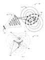
- FIG. 1 A fundamental issue with prior art optical digital imaging systems shown in FIG. 1 (upper drawing) that perform 3D localization is that resolution is related to the spatial density of image sensing pixels: specifically, pixels with fixed system geometries limit higher precision.
- SBP space-bandwidth product
- the baseline B between sensors determines the SPB, and hence precision of estimating x, y, z values for object 105 in system 100 .
- Optics 110 a and 110 b with focal lengths fa and fb, respectively, form images of object 105 at distances ya and yb, respectively, from the optical axis on their respective sensors 120 a and 120 b .
- the estimates of distances ya and yb determine y location and ratios of fa/ya and fb/yb determine the range, thus a more dense sampling at sensors 120 a and 120 b increases the precision of the estimations—but at the cost of higher size, weight and power.
- prior art radar systems also use arrays of detectors to detect objects in 3D space. Radar systems code across each element of a multi-element antenna array in order to detect/localize/reject, etc. targets in a 3D space in the presence of unknown noise and clutter. The number of antenna elements does not theoretically limit the potential angular estimation accuracy, except through SNR.
- the main differences between the radar system (lower drawing) of FIG. 1 and the optics system (upper drawing) of FIG. 1 is related to the fact that typical radar wavelengths can be temporally coherently sampled with antenna 102 a , 102 b , to 102 n .
- the antenna elements are arranged so that the field patterns from each element overlap.
- Mathematical weights 104 a , 104 b , to 104 n are applied across the array elements or channels and then summed 106 to determine the output signal squared 107 .
- the weights can be deterministic, such as Fourier coefficients, or can be a function of the sampled data, such as used in Auto-Regressive (AR) modeling, and can have a representation on the complex unit circle 108 in FIG. 1 where both signal amplitude and object angle can be represented.
- AR Auto-Regressive
- coded localization systems may include optics, codes, sensors and processors where the localization precision is related to the joint design of at least two of optics, codes, and sensors.
- coded localization systems form N samples of a remote object with each sample being coded with a unique code.
- coded localization systems are designed so that the cross-information between channels sampling the same remote object is reduced compared to no coding.
- coded localization systems where the codes in multiple measurements employ sinusoidal functions.
- coded localization systems where the N measurements form a measurement vector with a magnitude and phase as a function of spatial position.
- coded localization systems where the unbiased codes form an orthogonal set.
- coded localization systems where the sampled PSF of the imaging system is space-variant.
- coded localization systems the measured samples vary as a function of sub-pixel changes in the aerial image.
- coded localization systems where the measurement vector is compared to a stored or estimated object vector to detect the object and orientation and/or location.
- coded localization systems where multiple measurements of a remote object are made simultaneously in at least one domain of temporal, spectral, spatial and polarization.
- coded localization systems where measurements are made in the visible wavelengths.
- coded localization systems where the N measurements are configured to be unbiased.
- coded localization systems where the optics reduce the memory storage required compared to the FOV and localization uncertainty.
- coded localization systems where optics and data-dependent signal processing reduces the amount of data stored compared to classical imaging systems.
- coded localization systems where multiple systems are used for at least one of orientation and 3D localization.
- coded localization systems where the estimated or detected change in orientation or location is finer than the pixel spacing.
- coded localization systems where complimentary measurement vectors are used to estimate change in at least one of orientation and 3D location.
- coded localization systems provide measurement vectors that represent Fourier components beyond the spatial frequency limits of the detector pixels.
- coded localization systems where the coding is both spatial and temporal.
- coded localization systems where the complimentary channels are chosen in order to reduce the length of the overall optical system.
- coded localization systems provide complimentary measurements which are combined in digital processing to form a final image with resolution corresponding to the total number of measurements.
- a method and apparatus are provided for performing long range photo point measurements, with high precision compared to detector pixel spacing.
- a method and apparatus are provided for context-dependent optical data reduction and storage.
- a method and apparatus are provided for relative object location estimation with precision high compared to the number of pixels.
- a method and apparatus are provided for absolute orientation estimation.
- a method and apparatus are provided for absolute 3D location estimation.
- a method and apparatus are provided to transfer at least one of location and orientation reference information from a known point to a new point.
- a method and apparatus are provided to for data collection and data reduction for highway information.
- a method and apparatus are provided to for orientation and 3D location estimation for machine control.
- an improvement is provided for orientation and 3D location estimation for positioning.
- a method and apparatus for performing at least one of orientation and 3D location estimation for indoor applications In an embodiment, a method and apparatus for performing at least one of orientation and 3D location estimation for indoor applications.
- a method and apparatus for performing at least one of orientation and 3D location estimation for applications with unreliable GPS coverage is provided.
- a method and apparatus for performing at least one of distant object orientation and 3D location estimation for input to model building process is provided.
- the measures of angle to the object are used to count the number of objects in the field of view.
- the measures of angle from multiple sensors are used to count the number of objects in the combined field of view.
- each channel by coding differently more than one prior art pixel of information can be captured.
- each channel by coding each channel as a function of range a focusing can be achieved for objects not at infinity.
- each channel by coding each channel as a function of range an extended depth of field image can be achieved.
- an optical motion unit provides dead reckoning for navigation.
- a coded localization system includes a plurality of optical channels arranged to cooperatively image at least one object onto a plurality of detectors.
- Each of the optical channels includes a localization code to optically modify electromagnetic energy passing therethrough, and each localization code is different from any other localization code in other optical channels.
- Output digital images from the detectors are processable to determine sub-pixel localization of said object onto said detectors, and such that location of the object is determined more accurately than by detector geometry alone.
- a coded localization system includes a plurality of optical channels arranged to cooperatively image partially polarized data onto a plurality of pixels.
- Each of the optical channels includes a polarization code to uniquely polarize electromagnetic energy passing therethrough, each polarization code being different from any other polarization code in other optical channels.
- Output digital images from the detectors are processable, to determine polarization pattern for a user of the system.
- a method of localizing optical data includes cooperatively imaging at least one object onto a plurality of detectors while implementing localization codes uniquely to each optical channel, and processing output digital images from the detectors to determine sub-pixel localization of said object onto said detectors such that location of the object is determined more accurately than by detector geometry alone.
- the upper drawing in FIG. 1 is an example of a prior art optical location estimation system; while the lower drawing of FIG. 1 is an example radar based prior art localization system.
- FIG. 2 shows an embodiment of one coded localization system for location estimation; while the lower drawing of FIG. 2 provides a radar analogy.
- FIG. 3 shows an embodiment of a coded localization system, and a sensing and processing method in accord with another embodiment.
- FIG. 6 shows an embodiment of one coded localization system for imaging on a detector with overlapping fields of view.
- FIG. 7 is an embodiment of a coded localization system using single pixel detectors.
- FIG. 8 is an embodiment of a coded localization system using a priori information.
- FIG. 10 shows graphs of a 3 channel linear combination coded localization system that increases the Fisher Information on object location.
- FIG. 11 shows graphs of codes for a coded localization system performing sub-pixel imaging of a 1D line on a set of coded pixels.
- FIG. 12 illustrates codes for a phased sinusoidal coded localization system responding to a sub-pixel edge.
- FIG. 13 is an embodiment of a coded localization motility and motion observation and discrimination system with overlapping fields of view.
- FIG. 14 is an embodiment of a coded localization system showing 8 polarization steps with 2pi symmetry, or pi/4 phase steps, or pi/8 real rotation steps of a linear polarizer.
- FIG. 15 is an embodiment of the invention including stacking samples and performing spectral decomposition.
- FIG. 16 is an embodiment of the invention including stacking samples and performing spectral decomposition.
- FIG. 17 is an embodiment of the invention where the amplitude and bias are optimized for increasing exposure.
- FIG. 18 is an embodiment of a localization code that can be applied across the field of view of a bipolar two detector motion sensor system.
- FIG. 19 illustrates an embodiment where at least two coded localization systems can be used to estimate object range and velocity in addition to object angle and angular velocity from object motion.
- FIG. 20 is an embodiment of a coded localization system for motility and motion observation and discrimination.
- FIG. 21 illustrates an embodiment of the invention for motility and motion observation and discrimination.
- FIG. 22 is an embodiment of the invention with sampling diversity for coded localization systems.
- FIG. 23 illustrates an embodiment of coded localization systems forming images using overlapping FOV 2 ⁇ 2 systems.
- FIG. 24 is an embodiment of a design method for generalized coded localization systems.
- FIG. 25 is an embodiment of an optimized two pixel system.
- FIG. 26 is an embodiment of the invention and describes the construction of a code that enables both narrow FOV and wide FOV localization.
- FIG. 27 is one embodiment of a 4 channel linear combination system that increases the Fisher Information on object location.
- FIG. 28 is an embodiment of the invention that describes edge direction estimation.
- FIG. 29 is an embodiment of the invention for optimizing the design space for weight and number of pixels.
- FIG. 30 is an embodiment of a design method and trade space.
- FIG. 31 is an embodiment of the invention disclosing a measurement application.
- FIG. 32 is an embodiment of the invention disclosing a measurement application.
- FIG. 33 is an embodiment of the invention disclosing a measurement application.
- FIG. 36 shows the use of coded imaging channels to add information for human viewers.
- FIG. 39 shows an embodiment of a device for a polarization sky compass utilizing the coded designs.
- FIG. 40 shows another embodiment of a device for a polarization sky compass utilizing the coded designs.
- FIG. 42 shows a preferred embodiment of a device for imaging using the coded designs and processing systems.
- FIG. 43 shows a preferred embodiment of a device for imaging using the coded designs and processing systems.
- FIG. 44 is an embodiment of the invention disclosing ranging using groups of single pixels.
- FIG. 49 illustrates details of the imaging systems of FIGS. 39-43 .
- FIGS. 18-20 A two-pixel detector example that detects the location of a moving object is provided in FIGS. 18-20 ; this approach is extended to multi-aperture multi-pixel systems in FIGS. 20-22 to detect motion and orientation.
- the coded systems disclosed hereinbelow may also form full-resolution images as initially disclosed in FIG. 23 and shown again in later application FIGS. 24-30 . More complex codes and tasks with more apertures, with methods of design which include cross-talk and SNR considerations, are presented in FIGS. 24-30 .
- Applications of enabled devices performing profile measurements and localization tasks are provided in FIGS. 31-41 . More details about the devices that may be used in these applications are included in FIGS. 42-50 , along with example design parameters including codes, task requirements, processing algorithms, and numerical results.
- the channels are coded with codes 230 a and 240 a , and 230 b and 240 b and the coded images formed at sensors 220 a and 220 b are decoded to further determine y location and the range or z location of object 205 .
- codes are for example binary or real-valued intensity or phase screens, masks, and apertures, where the code varies as a function of spatial location in the image or aperture. Codes may also include polarization sensitive and selective materials.
- codes are placed in light path locations between the object and the sensor, for example between the object and the objective lens, between the aperture and the sensor, or distributed throughout the system.
- coded localization systems include coding of specialized optical systems across more than one aperture in order to optimize detection and localization estimation, increasing the information capacity of the system, and reducing system size. Such systems also become insensitive to knowledge of 3D system geometry and insensitive to environmental system tolerances. These systems enable spatially coherent 3D estimation even when the systems are geometrically and dynamically varying. These systems may include optics, codes, sensors and processors where the localization precision is related to the joint design of at least two of optics, codes, and sensors. Localization precision is dependent on system SNR and not on the number of pixels.
- a radar system analogy can be redrawn as an optical system by changing the location of the complex weights, squaring operator, and processing, and is shown in the lower drawing of FIG. 2 .
- the main differences between radar (lower drawing of FIG. 2 ) and optics (upper drawing of FIG. 2 ) relates to the fact that typical radar wavelengths can be temporally coherently sampled; yet optical wavelengths cannot yet be temporally coherently sampled.
- Wavelengths are spatially coherently sampled by detectors 207 a , 207 b to 207 n .
- the antenna elements are arranged so that the field patterns from each element overlap.
- an optical array of elements can be similarly arranged, such that the field patterns from each element or channel overlap.
- a distant object is imaged by multiple imaging channels.
- the imaging channels may have different chief ray angles, or boresight angles, to the object.
- the fields of view of different imaging channels overlap, at least in the volume where the distant object is located.
- each imaging channel is not a classical imaging system outside of the geometrical information just described; rather, each channel acts to code the relative angular location of distant objects as measured at the sensor.
- the coded localization systems thus form N samples of a remote object with each sample being coded with a unique code.
- the different coded information, as measured at the image sensors, is combined to enable high precision, fast computation, and the ability to enable image correspondence between the different image channels.
- coded localization systems are used to code angular information, relative to two or more sub-systems and/or two or more imaging channels on the same sensor. The relative angle and distance to a distant object is decoded with incomplete knowledge of optics and sensors (through environmental tolerances) or sub-systems (for example if sub-systems are moving relative to each other).
- coded localization systems are used to improve estimates of angular location and distance in situations where knowledge of optics and sensors are known.
- coded localization systems are used to reduce the search space when estimating image correspondence by constraining the search to regions of corresponding localization codes.
- FIG. 3 shows an embodiment of a coded localization system 300 .
- coded localization system 300 is configured to record N channels with optics 310 to 310 n and sensors 320 to 320 n .
- each channel records 2D spatial, and possibly color and temporal information, for a particular code 340 to 340 n .
- channel codes 340 to 340 n differ at least by a different polarization value or angle of polarization.
- channel codes 340 to 340 n differ at least by an intensity of spatially varying attenuation.
- channel codes 340 to 340 n differ at least by a phase of spatially varying intensity.
- channel codes 340 to 340 n differ at least by a phase of spatially varying sinusoidal intensity. In another embodiment, channel codes 340 to 340 n differ at least by a value of spatially varying optical path length. In another embodiment, the channels consist of at least one of an image, aperture, wavelength, polarization, and field of view.
- Lens 395 is an optional objective lens that cooperates with optics 310 to 310 n to form a re-imaging configuration wherein the optics 310 to 310 n function as a micro lenses array to re-image portions of the field through codes 340 to 340 n . If lens 395 is not present, optics 310 to 310 n form individual objective lenses for each of the coded imaging channels.
- the data set 370 from system 300 is a three dimensional matrix M(x,y,p) where (x,y) are spatial variables 350 and p is at least one of a polarization, intensity, and optical path variable 360 .
- Color and temporal variables may be embedded into each spatial domain matrix Mi through such configurations as Bayer color filter arrays, temporal averaging, etc. Temporal information may also be made explicit through an additional dimension of the matrix M.
- processing system 380 combines data 370 containing matrix M according to the signal to be extracted from the coding sequence 340 to 340 n .
- the spectral analysis is demonstrated in subsequent paragraphs to enable a polarization compass among other devices.
- the spectral analysis may be at least one of temporal and spatially varying and may include at least one of a spectrogram analysis, a space-frequency analysis, a scale-space analysis, and a time-frequency analysis.
- the sub-signals are averaged and the average is analyzed for spectral content.
- the codes in multiple measurements employ sinusoidal functions.
- FIG. 4 shows an embodiment of one coded localization system 400 employing polarization codes.
- a number of illumination objects, 491 a , 491 b , 491 c are modified by unknown source codes 492 a , 492 b , 492 c and form signals 493 a , 493 b and 493 c .
- source codes 492 a , 492 b , 492 c are for example linear polarizers.
- the number of these objects, source codes and signals is one, for example as may be modeled while viewing a very narrow portion of the polarized sky.
- the number of these objects, source codes and signals is larger than one, for example when viewing a wide field of view of the polarized sky the polarization may be modeled by a very large number of objects, source codes and signals that vary in angle and magnitude across the sky.
- the signals 493 a , 493 b and 493 c emanating from the sources/source codes are describable in a spatial, temporal and spectral domain.
- a generally unknown medium 480 between the sources/source codes and the sensing systems 405 acts to corrupt the signals 493 a , 493 b and 493 c .
- a specialized sensing system is a collection of optically coded systems 405 to 405 n containing codes 440 to 440 n , optics 410 to 410 n , and detectors 420 to 420 n .
- codes 440 to 440 n are implemented in the polarization domain through polarization analyzers.
- codes 440 to 440 n are implemented through linear polarization with varying physical angles.
- the collection of optically coded systems 405 to 405 n is designed to record the spectral, spatial, temporal and polarization information such that accurate and reliable information is captured in the presence of the unknown medium 480 .
- processing the recorded data by process 470 is used to extract the needed localization information from the recorded data.
- codes 440 to 440 n are implemented through amplitude masks above the sensor planes of detectors 420 to 420 n where the collection of optically coded systems 405 to 405 n is designed to record the spectral, spatial, and temporal information such that accurate and reliable information is captured in the presence of the unknown medium 480 .
- FIG. 5 shows an embodiment of one coded localization system 500 .
- Lens system 510 contains several different fields of view L 1 , R 1 , L 2 , R 2 , L 3 , and R 3 .
- Detectors 520 and 521 outputs are combined in a bipolar fashion to produce signal 515 when system 500 is exposed to motion 505 in the sensing field.
- Processing system 570 processes information in signal 515 .
- at least one of complimentary lens regions 550 , 551 and 552 is purposely designed so that the measured signals at the output of the dual-element sensor 520 , 521 are different for the left and right fields of view for one or more imaging channels.
- region 550 may be partially attenuating, by screening or blocking at least a portion of the outermost lens surface.
- region 551 or 552 may be at least partially attenuating, so that the response of detector 521 or 520 respectively is altered.
- Example output 590 indicates a sinusoidal-like response for each of the L and R (or + and ⁇ ) detector pixels within regions labeled 1 through 6 in graph 590 corresponding to each of the lenses labeled 1 through 6 in 580 .
- Signal 595 is clearly attenuated peak-to-peak within region 3 , indicating that the moving object was in the zone of lenses 1 - 3 covering a half of the field of view. In this case the difference in the signal amplitudes indicates the angular location or field location of the moving object. Without the coded lens (i.e., in the prior art), all field points will appear identical and angular location cannot be determined.
- the processing system 570 processes signal 515 to detect the signature caused by the localization coding in region 550 to produce a measure of angle to the object that caused the motion.
- the measures of angle to the object are used to count the number of objects in the field of view.
- the measures of angle from multiple sensors are used to count the number of objects in the combined field of view.
- the aerial image sub-pixel instantaneous fields of view I s are weighted by a mask and summed together on sensor 620 to form the coded sample 673 .
- all four fields of view 602 may be formed as image circles 621 on a single detector array 620 .
- Each of the four channels has essentially the same information at the proper corresponding x/y locations before coding due to the overlapping fields of view 602 .
- the localization codes on masks 641 , 642 , 643 , 644 for the different imaging channels have different functions and include at least one of spatial phase, spatial amplitude, polarization and optical path difference.
- the mask locations vary in the distance they are located between the lens 610 and the sensor 620 (e.g., the mask for any one channel is located at a different location along the optical path as compared to the mask in another channel).
- the codes are composed of at least one of a smooth function, a rapidly varying function, and random or pseudo random functions that provide a broad set of basis functions for designing codes with many degrees of freedom.
- the codes for a 2 ⁇ 2 implementation is a code composed of biased sinusoids such that the code maximizes the Fisher Information of a general scene.
- the measured samples vary as a function of sub-pixel changes in an aerial image, enabling sub-pixel resolution measurements, or measurements at a finer scale than the pixel spacing.
- the codes include wavelength specific codes. Masks 641 , 642 , 643 , 644 may select wavelengths, in one embodiment, and be sensitive to a selection of wavelengths in another embodiment. By selecting a wavelength the codes can perform hyper-spectral filtering as well as sub-pixel location information.
- each object point is imaged in at least two of a selection of visible wavelengths, near-IR, mid-wave IR, and long-wave IR wavelengths for broad spectrum imaging and use in imaging and targeting systems that fuse at least two of visible, near-IR, and long-wave IR images.
- FIG. 7 shows an embodiment of one coded localization system 700 ; system 700 employs single pixel detectors.
- two imaging channels are mounted in such a way that the boresight (or on-axis) directions are all parallel.
- the two pixels 720 have overlapping fields of view 702 that form intersecting contours 708 .
- Contours indicate constant detected values as a function of object position. This enables estimation or detection of the location of an object using only two pixels. The fewer number of pixels required to perform a given task results in lower power and size.
- the location of an unknown object point in the field of view has an uncertainty between locations ‘a’ and ‘b’ in the intersecting contours 708 .
- a priori knowledge exists to differentiate between locations ‘a’ and ‘b’.
- FIG. 8 shows an embodiment of coded localization system 800 using a priori information.
- the object or optical data of the word “GENERIC” is known in advance as 810 (and 810 may be created by known prior art). From this information a collection of known measurement vectors 820 is formed and later used to test against the actual sampled measurement vectors 830 in order to perform at least one task of detection, localization, ranging and multi-channel correspondence. If 810 is an image, then the number of samples forming 810 can be much larger than in the sampled or known measurement vectors 820 and 830 . In one embodiment the vector 820 contains reduced data compared to the source 810 .
- the formed measurement vectors 820 and the sampled measurement vectors 830 can be normalized and so form a vector metric for sub-pixel localization of the generally complicated target 810 .
- the actual sampled measurements 830 are compared at a vector level to the modeled vectors 820 and a vector norm calculated as a matching metric using processor 870 .
- the measurement vector is compared to a stored or estimated object vector to detect at least one of the object, object orientation and object location.
- the measurement vector is used with a mathematical model of the object to estimate object parameters.
- the system of FIG. 8 applies to an “object camera” or “object sensor”. That is, in a large number of applications information is only desired about certain type of objects, or certain classes of objects. Some applications may only be interested in capturing information about location and dimensions of telephone poles. Other applications may only be interested in the number of locations of people. All other collected data that doesn't represent information about either telephone poles or people is not really wanted and could be discarded as a pre-processing step.
- a model of a set of objects 810 is collected and then reduced to the possible known measurement vectors 820 .
- the sampled measurement vectors 830 are compared to the known measurement vectors and objects in the set of application-specific objects are then detected, and information about these objects further detected or estimated, such as their orientation, location, position, etc.
- human viewed images corresponding to regions about the detected object can then be formed as shown in FIG. 23 from the sampled or known measurement vectors.
- the normalized vector method enables an invariance to object gain, as the vectors capture direction and relative magnitude.
- the normalized vector method enables a low sensitivity to additive noise as the process is bipolar.
- the normalized vector method enables an error magnitude as well as direction for fast detection and a combination of detection and estimation steps.
- a method and apparatus are provided for context-dependent optical data reduction and storage.
- each arm 910 , 920 and 930 forms motion estimates 912 as [dx1, dy1], motion 922 as [dx2, dy2], and motion 932 as [dx3, dy3], respectively for each arm, along and orthogonal to the direction of the arm.
- arms 910 , 920 and 930 also provide details D 1 , D 2 , and D 3 for each of the motion estimates 912 , 922 , and 932 , respectively.
- details D 1 , D 2 , and D 3 are at least one of an estimate of signal quality and noise levels, structure information such as polarization state and wavelength intensity variance, object specific features and energy information such as spatial frequency modulation and intensity across field.
- electromagnetic energy 995 may be further modified by the physical media 996 prior to detection for example to affect at least one of a polarization state, a wavelength, a spatial intensity and a modulation of a spatial frequency.
- physical media 996 may also impart a variation between modifications to electromagnetic energy 995 among the arms 910 , 920 , and 930 to affect at least one of the optical properties of magnification variation, field of view, optical axis skew, field intensity variation, field polarization variation, and field aberration content.
- a method for design of coded localization systems included maximizing the information for a given task.
- Imaging systems are often designed to produce visually pleasing pictures. In cases when the systems are producing information, design methods related to information are required.
- a preferred method is system design that minimizes the Cramer-Rao bound and maximizes the corresponding Fisher information for particular aspects of the 3D scene information.
- coded localization systems are designed so that the cross-information between channels sampling the same remote object is reduced compared to no coding.
- the sum of the output of coded imaging channels is essentially independent of the independent variable or variables in the domain of the codes.
- Design of these coded systems can be understood through information theory. Designing via methods disclosed herein can maximize the possible precision of estimated parameters, or more generally, increase the information capacity of the coded system relative to the object parameters of interest.
- the Fisher Information matrix J is a fundamental matrix related to the overall system that describes the sensitivities of the system to the expected unknowns. Assume the measurements y are defined by a set of unknowns. Then the elements of J are products of the partial derivatives of the measured signals with respect to the unknowns. In the additive Gaussian noise case the Fisher Information matrix can be written as
- J ij d ⁇ y _ T d ⁇ ⁇ ⁇ i ⁇ R - 1 ⁇ d ⁇ y _ d ⁇ ⁇ ⁇ j
- J ij ⁇ # ⁇ ⁇ of ⁇ ⁇ channels ⁇ [ info ⁇ ⁇ on ⁇ ⁇ x o ⁇ Xinfo ⁇ ⁇ on ⁇ ⁇ x o ⁇ ⁇ ⁇ Xinfo ⁇ ⁇ on ⁇ ⁇ x o ⁇ info ⁇ ⁇ on ⁇ ⁇ x n ]
- the desired information is the parameter x o .
- the Fisher Information matrix contains entries related only to the system information about x o , as well as what's called cross-information about x o and the other unknowns, as well as information about the other unknowns.
- the cross information on x o can be considered a nuisance parameter as its presence negatively contributes to estimating the value of x o .
- the nuisance parameters increase the related Cramer-Rao bound on the parameter x o .
- a goal is to maximize the overall system information about a particular parameter while also minimizing the cross information related to the same parameter. This will result in a system optimized to estimate the chosen parameters from the crowed object information space.
- the partial derivatives of this model are
- the upper right and lower left hand quantities are the nuisance parameters for the quantity x o .
- minimizing the Cramer-Rao bound on x o is equivalent to diagonalizing the Fisher Information Matrix J. This happens when
- the form of the individual channel codes can be a sum of cosines where the frequency of each cosine is a harmonic of a fundamental period. The phase of the sum of cosines for each channel is designed so that the Fisher Information is diagonal.
- the form of the individual channel codes can be a sum of products of cosines where the fundamental frequency of each cosine is a harmonic of a fundamental period. The phase of the sum of products of cosines for each channel is designed so that the Fisher Information is diagonal.
- Incoherent imaging systems are non-negative.
- h 1 (x) 0.5 sin(wx)+0.5
- the sum of cosine and sums of products of cosine codes also has a bias term in order to make the code non-negative.
- the non-negative requirement forces the amplitude of individual sinusoidal components to decrease in multi-sinusoidal code models. This has the effect of reducing the information capacity related to those particular code components.
- FIG. 10 illustrates graphical data from a 3 channel coded system that increases the Fisher Information on object location.
- Graph 1010 is from a system of three unipolar or non-negative channels.
- Graph 1030 is from a system of three bipolar channels, or the channels from 1010 but without the bias term.
- the additive noise is considered to be the same for both the biased and unbiased systems.
- the equations of the sinusoids are given by cos(2pi x+phase), where x ranges from ⁇ 0.5 to +0.5.
- the phase of the three sinusoids are 30 degrees, 150 degrees, and 270 degrees, which are 2pi symmetric with a 120 degree separation.
- the unbiased channels are bipolar (have negative values). While a temporally incoherent optical system cannot have negative measurements, the 3 channel biased system of 1010 can have identical information about the unknown position variable x as the unbiased system.
- the Fisher Information related to measurements 1010 is shown in 1020 , and for 1030 is shown in 1040 . These Fisher Information plots also include an unknown additive bias term. With proper system design the addition of unknown bias does not negatively affect the captured information about the desired parameter or parameters.
- the value of information about variable x is the same in 1020 and 1040 .
- the cross information related to X is zero for both 1020 and 1040 .
- the non-zero cross information curve in 1020 is related to the cross information between G and B.
- FIG. 11 shows graphical data 1100 for a coded localization system performing sub-pixel information gathering, detection and estimation of a 1D line on a set of coded pixels.
- the set of coded pixels, the codes, and the disparity of the codes constitute a “system” as a functional description used hereinafter.
- the top row shows the aerial images of a line as it would appear during one period of the codes before sampling.
- the period of the codes is over one or less pixels. In another embodiment the period may be over many pixels.
- the pixel codes are biased sinusoids and cosines and the measured data is the inner product of the individual codes with the aerial image data.
- the imaging model is unknown gain, bias and vertical line location and 4 codes record each of the horizontal or vertical sub-pixel dimensions of the line.
- the difference between the two 180 degree out of phase channels is a bipolar sign with no bias.
- the two sets of differences yield two bias-free measurements that are together shifted in phase by 90 degrees. These two measurements may represent the real and imaginary part of the Fourier Transform coefficients at one spatial frequency of the sub-pixel object.
- the complex representations of these differences of Fourier transform measurements are represented as the horizontal and vertical vectors in the row of unit circles shown in FIG. 11 .
- the two vectors have been scaled so that the largest magnitude is one, and the vector with the smaller magnitude is scaled proportionately to one. In the case of imaging a vertical line, all the vertical vectors have essentially zero magnitude.
- the horizontal vectors directly indicate the sub-pixel location of the vertical line.
- a priori when the gain and bias were known a priori then only 2 codes phased by 180 degrees are needed for each vertical or horizontal direction of the object.
- the a priori knowledge is obtained from an un-coded channel.
- An example of such codes is given in system 1150 with graphs 1180 and 1190 .
- Graphs 1180 and 1190 describe a “system” as they show the system design aspects (the code values), with two different codes as the system requires, and the associated Fisher information, that enables the results shown in 1100 .
- Graph 1180 in FIG. 11 shows two sinusoidal codes that have 2pi symmetry, or are phased by 180 degrees. A bias has been added so that the amplitude of the codes is non-negative.
- the Fisher Information on related to these codes is shown in graph 1190 .
- FIG. 25 shows two examples of two channel codes that illustrate other choices.
- the channel codes in FIG. 25 are polynomial codes.
- the two channel codes 2500 of FIG. 25 have 2pi symmetry (or the sum of the codes are constant as a function of spatial position) as shown in 2510 .
- the square root of the inverse of the Fisher Information, or Cramer Rao Bound (CRB), for this system is described in 2520 .
- the CRB for this system is also biased but has less change than does the equivalent CRB for the two channel system 1150 in FIG. 11 .
- System 2550 in FIG. 25 describes another related design that does not exactly hold 2pi symmetry but does achieve an unbiased CRB, and therefore an unbiased Fisher Information as shown in 2560 .
- the collection of graphs in 2550 is considered a “system” since it describes the design of the codes, the orthogonality of the code designs, and the Fisher information achieved.
- Each code taken alone is unimportant, rather it is the inter-relationship of the codes or the system-level accomplishment of the combination of codes that is important.
- There are numerous other two channel codes such as those in FIG. 11 and FIG. 25 that balance the need for orthogonality, non-negativity, 2pi symmetry and CRB/Fisher Information bias.
- FIG. 12 shows a phased sinusoidal coding for a localization system 1200 and responding to a sub-pixel edge.
- the edge is a vertically aligned edge so the vertical measurement vectors have zero magnitude.
- the horizontal vector being the Fourier Transform at one spatial frequency of the sub-pixel imagery, shifts with the location of the edge.
- the location of the sub-pixel edge location can be directly measured from the horizontal measurement vector.
- system 1200 uses 4 phased channels per direction with no a priori knowledge of the edge gain and bias.
- system 1200 uses 2 phased channels per direction with a priori knowledge of the edge gain and bias.
- the number of actual unknowns in the image data is larger than the unknowns that are actually desired.
- the image gain and bias are two quantities that are often considered less important in 3D imaging/ranging than the range to particular spatial features.
- hi-resolution imagery is acquired and used to model the sampled measurement vectors a priori. With this high resolution information the gain and bias can be considered known.
- high-level and high resolution image processing features may be used to guide the image processing.
- a high resolution imaging system is equipped with coded localization systems that provide measurements in 3D that are used in conjunction with the high resolution images to augment disparity in multi lens camera systems.
- the augmented disparity is used to generate coordinates for at least one of entertainment, mapping, navigation, survey and geoinformation systems.
- an estimate of bias is formed through the sum of the outputs of the measurement channels.
- the sum of the measurement channels can be an accurate measure of the bias (code bias plus the bias from the object, system, etc.) if the codes are designed with 2pi symmetry.
- An important characteristic of 2pi symmetry is that the sum of the measurement channels can be a constant for a particular object in the domain of the code. Re-consider the 3 channel measurement system of 1010 from FIG. 10 .
- the sum of the codes or measurements 1010 is a constant as a function of normalized location. The sum of the code then provides no information about location, only information about bias.
- codes designed to have 2pi symmetry are those where the sum of the measurement channels is independent of the particular domain variable, be it spatial, polarization, temporal, etc.
- spatial coding a set of codes has 2pi symmetry if the combination of PSF and spatial codes, when all channels are summed, produces a sampled value that is ideally independent of spatial location.
- a multi-aperture 2 ⁇ 2 system with 2 horizontal and 2 vertical sinusoidal codes can have 2pi symmetry if the sinusoids for each channel are out of phase by 180 degrees.
- Design of codes also depends on field of view arrangements of multiple channels including overlap and adjacency, or system field of view (SFOV), as well as the task at hand (where is that, and where am I), where codes that have overlapping fields of view or specialized SFOVs can provide multi-channel signals with more information than independent and un-coded sensors when detecting objects or motion and also discriminating between global and local motion.
- SFOV system field of view
- FIG. 13 is an embodiment of a coded localization motility and motion observation and discrimination system 1300 .
- each arm 1340 , 1350 and 1360 forms motion estimates 1342 , 1352 , and 1362 respectively, within overlap regions 1392 formed by the overlap of large region 1364 with smaller regions 1344 and 1354 .
- the motion estimation 1342 , 1352 , and 1362 also contain details D 4 , D 5 , and D 6 are for example independent estimates of wavelength intensity.
- details D 4 , D 5 and D 6 contain polarization intensity and angle.
- each arm 1340 , 1350 and 1360 in reference coordinate system 1380 are coupled based on a frame formed by arms 1340 , 1350 and 1360 overlap regions 1392 .
- the motion estimates 1342 , 1352 , 1362 and details D 4 and D 5 are independent from each other.
- the details D 6 from region 1364 have a partial dependence on regions 1344 and 1354 .
- system 1300 when rotated about the z axis, has a system field of view (SFOV) consisting of sparse region 1393 panned across a region (indicated by arrow 1395 ) such as sky, resulting in a SFOV shaped like a band with a finite extent of elevation and 360 degrees in azimuth.
- SFOV system field of view
- Features 1394 are in one embodiment at least one of a measure of polarization strength and direction.
- features 1394 are in another embodiment a response to polarization codes from the coded localization systems.
- various parameters of the features 1394 are reported in the details D 4 , D 5 and D 6 .
- details D 4 , D 5 , and D 6 contain at least one of parameters related to contrast, intensity contours, wavefront slope, and wavelength information.
- system 1300 provides details D 4 , D 5 , and D 6 for regions contained within the SFOV where the details contain polarization for sky for at least a portion of the SFOV.
- the pattern of vectors in the at least one portion of the SFOV provides geocentric azimuth, elevation and roll estimates from polarization patterns in the sky.
- motion and motility estimates of the reference coordinate system 1380 such as motion 1395 across pattern 1394 allow the portions of the SFOV to be mapped into an adaptive sky model.
- the adaptations include influences from near-horizon effects including at least one of pollution, dust, smoke, and thermal gradient wavefront distortion.
- the unknown medium of FIG. 4 is included in system 1300 and acts to change the degree of polarization, often to a very low value that can be recovered by use of the invention disclosed herein.
- the unknown medium of FIG. 4 is at least one of clouds, fog, thermal gradient wavefront distortion and pollution.
- the collection of optics and detector of system 1300 have some particular field of view (FOV), which may be a portion of the overall SFOV, and instantaneous field of view (iFOV) and forms N measurements.
- the iFOV is the FOV of a particular pixel.
- the iFOV may be a function of the particular pixel, through for example, distortion of the optics.
- coded localization systems are disclosed where the sampled PSF of the imaging system is space-variant.
- the N measurements form a measurement vector as a function of spatial position.
- the N measurements form a measurement vector with a magnitude and phase as a function of spatial position.
- the N measurements are configured to be unbiased.
- the N measurements are designed so that the sum of the squares of the N measurements is constant in the absence of noise.
- the system 1300 produces the data matrix M in FIG. 3 through the unknown medium 480 in FIG. 4 .
- (x1,y1) is the spatial location of the data in M.
- the unknown medium 480 in FIG. 4 as applied to system 1300 just imparts a constant magnitude or gain and bias over spatial, spectral, temporal and polarization domains of the measured data.
- M is a vector of M and G is an amplitude dependent on the signal 493 a - c in FIG. 4 , the unknown medium 480 attenuation and the sensitivity of the sensing system 1300 .
- the phase phi1 is related to the relative orientation of the signal and the sensing system.
- the Bias is also related to the signal, the unknown medium and the sensing system.
- wi is considered known and is related to the rotation of the coding elements 340 to 340 n in FIG. 3 and coding elements 440 to 440 n in FIG. 4 when the coding elements form a polarization analyzer.
- the degree of partial polarization can be given by the ratio of G to the Bias.
- orientation is determined using G and phi1.
- data M is acquired with minimized Bias and maximized G.
- data M is acquired with equal Bias and G.
- the sensing of M is always in the presence of noise.
- the estimation of G, phi1 and Bias is then a statistical estimation problem.
- the best possible estimation performance can be described in terms of Fisher Information and Cramer-Rao bound for this particular embodiment.
- design of the sensing system 1300 involves optimizing the system to maximize the Fisher Information relative to the quantities of interest while reducing the cross information with other quantities. This is equivalent to reducing the Cramer-Rao bound for the best possible unbiased estimation performance of particular parameters of the system.
- the parameters to be estimated include at least one of a linear polarization angle and magnitude.
- the Fisher information matrix is created by the inner products of the partial derivatives the data model M with respect to the system unknowns G, phi1 and Bias.
- J ( i,j ) [ d M /d (theta i )] T [d M /d (theta j )
- shot noise is minimized by adjusting exposure time to minimize Bias while maximizing G.
- shot noise is minimized by adjusting sensor sensitivity to minimize Bias while maximizing G.
- shot noise is balanced with read noise by adjusting sensor sensitivity to equalize Bias and G.
- the design the coded localization system will choose the channels of the polarization domain so that the cross information between unknowns is zero or as low as possible while also acting to increase the Fisher Information of the desired unknowns.
- the unbiased codes sum to zero.
- unbiased codes form an orthogonal set.
- the amplitude of the signals 493 a - c in FIG. 4 can be very small relative to the noise level of the sensing system 1300 .
- High noise levels lead to a reduction of localization precision.
- the signal amplitude in the polarization domain can be less than 1% of the full scale signal.
- the amplitude of the detected signal can be about 0.01*1024 or about 10 counts out of maximum of 1024 measured grayscale counts.
- FIG. 14 is an embodiment of a coded localization system showing 8 polarization steps with 2pi symmetry, or pi/4 phase steps, or pi/8 real rotation steps of a linear polarizer. In one embodiment to improve the estimate of the polarization signal amplitude and phase more polarization steps can be used.
- FIG. 14 shows graph 1410 with 8 polarization steps with 2pi symmetry, or pi/4 phase steps, or pi/8 real rotation steps of a linear polarizer.
- Graph 1420 in FIG. 14 shows the result of this signal in shot noise.
- the use of more than the minimum number of polarization phase samples is useful for detecting when the actual measured signal does not correspond to a sinusoidal model.
- the iFOV can be made small compared to the angular extent of the signals as seen by the sensing system.
- the iFOV is smaller than the signal angular extent a larger number of samples can be used in the estimation of the unknowns thereby increasing estimation precision in unavoidable noise.
- the received data can be configured such as: [ ⁇ right arrow over ( M ) ⁇ ( x 1, y 1; M ( x 2, y 2); M ( x 3, y 3); . . . ; M ( xN,yN )]
- the received data can be configured such as: 1/ N* ⁇ i M ( xi,yi )
- FIG. 14 graph 1430 illustrates an embodiment for spatial concatenation of 2pi symmetric polarization samples to increase the ability to estimate signal phase in noise.
- Any one imaging channel is represented by graph 1420 .
- Graph 1430 shows the polarization samples in 4 ⁇ 4 spatial neighborhoods with additive shot noise.
- Graph 1440 is the Fourier Transform of graph 1430 , plotted as 20*log 10 of the Fourier Transform of the data. While graph 1430 can be considered roughly a sinusoid graph 1440 clearly shows the sinusoidal nature of the signal indicated as peaks 1445 in the spectrum.
- the phase of the signal at the signal peaks 1445 can be estimated from the phase of the complex values of the Fourier Transform.
- the variance of best possible unbiased estimate of the signal phase is dependent on the amplitude of the signal. As the signal amplitude decreases the ability to estimate the phase also decreases, or the variance of the best unbiased estimator of signal phase increases.
- the processing required to estimate the phase of unknown polarization signals can change as a function of the signal amplitude or degree of polarization. In contrast, as the signal bias increases so too does the noise. In an embodiment the processing required to estimate the phase of unknown polarization signals can change as a function of at least one of the signal bias and degree of de-polarization.
- FIG. 15 is an embodiment of the invention including stacking samples and performing Fourier decomposition.
- Graph 1510 shows a noise-free sinusoidal signal that has been stacked as described in FIG. 4 to form a long signal.
- Signal 1510 has a bias of 200, degree of polarization 1%, amplitude 2 with 8 polarization angles across 40 ⁇ 40 spatial samples with no noise.
- Graph 1520 shows the Fourier transform of the signal in graph 1510 .
- Graph 1530 shows the signal in graph 1510 with shot noise.
- Signal 1530 has a bias of 200, degree of polarization 1%, amplitude 2 with 8 polarization angles across 40 ⁇ 40 spatial samples with shot noise.
- the Fourier transform is used to estimate the magnitude and phase of the underlying signal as shown in graph 1540 as peaks 1545 .
- the sinusoids are clearly above the noise in the spectral analysis.
- FIG. 16 is an embodiment of the invention including stacking samples and performing Fourier decomposition.
- Graph 1610 shows a sinusoidal signal that has been stacked as described in FIG. 4 to form a long signal.
- the difference between 1610 and 1530 is that the exposure related to 1610 has been reduced by approximately a factor of 10 compared to 1530 . This reduction in exposure reduced the signal bias and shot noise but not the signal amplitude.
- Signal 1610 has a bias of 20, degree of polarization 1%, amplitude 2 with 8 polarization angles across 40 ⁇ 40 spatial samples with shot noise.
- Graph 1620 shows the Fourier transform of the signal in graph 1610 .
- the sinusoids are clearly above the noise in the spectral analysis.
- the optics reduce the memory storage required compared to the FOV and localization uncertainty. In another embodiment optics and data-dependent signal processing reduces the amount of data stored compared to classical imaging systems.
- the SNR can vary spatially across typical images. Therefore the ability to implement a spatially varying process will further improve results, for example by correctly selecting the number N or the fundamental exposure time to use in given FOV or iFOV.
- the bias can be increasing the exposure time can be optimized to equalize gain and bias.
- arms 1340 , 1350 , and 1360 in FIG. 13 have different exposure times providing spatially varying sampling if G and Bias in the SFOV.
- the object space is not sparse and is highly variable and the task is insensitive to such a signal and very few detector elements can be utilized to understand the information in the object space.
- the code can become smooth and continuous vs. FOV.
- FOV K the particular complimentary lens region k would then produce a signal measured be the sensor with amplitude of A(L K ) and A(R K ) times some unknown gain.
- an angle and gain normalized code represented in FIG. 18 is such that the left channel 1810 is represented by x,
- the values of L(x) and R(x) are equivalent to A 1 and A 2 on FIG. 5 .
- angle can be estimated as a function of time the angular velocity of an object between any adjacent positions in x can be determined by differentiating Estimate(x).
- FIG. 19 illustrates an embodiment where at least two coded localization systems can be used in system 1900 to estimate object range and velocity in addition to object angle and angular velocity from object motion 1905 .
- system 1900 contains at least two systems where each system is similar to that of FIG. 5 and contains bipolar detector pairs 1920 .
- the two systems can also be combined within a single optic 1910 .
- the object motion 1905 is at least one of constant and nearly zero and system 1900 undergoes at least one of translation and rotation to scan the object field of interest.
- range estimates can be formed independent of the gain of the system, intensity of the object, etc.
- An object with some motion vector 1905 traversing two complimentary lens regions A(Li) A(Ri) and A(Lk) A(Rk) produce two temporal output signals 1915 i and 1915 k respectively.
- the output signals 1915 i and 1915 k are amplitude coded and temporally coded.
- the amplitude code is due to the code designed into the complimentary lens regions.
- the temporal code is due to the general optical characteristics and the direction and speed of motion of the object.
- the two codes are providing complimentary information to processor system 1970 and so in one embodiment can be used to further increase the precision of the range and velocity estimates if the baseline separation of the two systems, B, is known.
- the complimentary information can be used to directly estimate the baseline B as well as the range and velocity of the unknown objects.
- complimentary measurement vectors are used to estimate change in at least one of orientation and 3D location. There is only one baseline B which will yield the corresponding amplitude and temporal codes for the unknown distant object velocity vector as measured by the two detector outputs yielding a discriminating signal for multiple inputs.
- system 1900 is able to count discrete objects in motion 1905 within the field of view of system 1900 .
- FIG. 20 shows an embodiment of a coded localization system 2000 for motility and motion observation and discrimination.
- the arrangement of arms 2010 , 2020 and 2030 may be coplanar with axes ⁇ x and ⁇ y and orthogonal to ⁇ z in reference coordinate system 2080 .
- each arm 2010 , 2020 and 2030 forms motion estimates 2012 2022 , and 2032 respectively, in directions orthogonal to ⁇ z, within partially-overlapping regions 2014 , 2024 , and 2034 .
- the overlap region is shown as hatched region 2092 in subsystem 2090 .
- the motion estimation 2012 , 2022 , and 2032 also contain details D 1 , D 2 , and D 3 are at least one of independent estimates of signal confidence, noise level, signal level, wavelength, wavefront phase, wavefront amplitude, and polarization direction and polarization magnitude of the partially-overlapping regions 2014 , 2024 , and 2034 and overlap region 2092 .
- details D 1 , D 2 , and D 3 are also for example object specific information including at least one of object edges, object corners, object structures, object texture and features of interest for an object.
- details D 1 , D 2 , and D 3 contain statistics about object specific information.
- each arm 2010 , 2020 and 2030 in reference coordinate system 2080 are coupled based on a frame formed by arms 2010 , 2020 and 2030 and overlap region 2092 .
- the motion estimates 2012 , 2022 , 2032 are independent of each other and so a number of useful relationships and constraints exist between the independent motion estimates and the coupled constraints of the geometry in system 2000 with respect to reference coordinate system 2080 and an overlap region 2092 .
- system 2000 may contain electromagnetic energy converters 2097 for converting energy 2095 into intensity and a physical media 2096 for transporting electromagnetic energy to the electromagnetic energy converters 2097 .
- Converted data is processed by process 2098 to form a set of N+1 motion estimates 2099 denoted d 0 , d 1 , . . . , dN.
- Electromagnetic energy 2095 may be in the form of ultraviolet to visible to long wave infrared wavelengths, acoustical wavelengths and radio wavelengths for example.
- electromagnetic energy 2095 may be further modified by the physical media 2096 prior to detection for example to affect at least one of a polarization state, a wavelength, a spatial intensity and a modulation of a spatial frequency within the overlap region 2092 .
- physical media 2096 may also impart a variation between modifications to electromagnetic energy 2095 among the arms 2010 , 2020 , and 2030 to affect at least one of the optical properties of magnification variation, field of view, optical axis skew, field intensity variation, field polarization variation, and field aberration content within the overlap region 2092 .
- FIG. 21 illustrates a coded localization system 2100 for motility and motion observation and discrimination.
- the arrangement of arms 2110 , 2120 and 2130 may be coplanar with axes ⁇ x and ⁇ y and orthogonal to ⁇ z in reference coordinate system 2180 , while arms 2140 and 2150 may be coaxial with ⁇ z.
- each arm 2110 , 2120 , 2130 forms motion estimates 2112 , 2122 , and 2132 , respectively, in the directions orthogonal to ⁇ z, within non-overlapping regions 2114 , 2124 , and 2134 that intersect with surface 2182 .
- each arm 2140 and 2150 forms motion estimates 2142 and 2152 , respectively, in the directions coaxial to ⁇ z, within non-overlapping regions 2144 and 2154 that do not intersect with surface 2182 .
- the motion estimation 2112 , 2122 , 2132 , 2142 and 2152 also contain details D 1 , D 2 , D 3 , D 4 and D 5 .
- details D 1 , D 2 , and D 3 are for example independent estimates of the contrast and structure in surface 2182 and details D 4 and D 5 are at least one of estimates of the polarization, intensity, contrast and structure for regions 2144 and 2154 containing at least one of scattered sunlight, starlight, and moonlight.
- multiple systems are used for at least one of orientation and 3D localization.
- multiple systems are used to estimate change in at least one of orientation and 3D location.
- the estimated or detected change in orientation or location is finer than the pixel spacing.
- each arm 2110 , 2120 2130 , 2140 and 2150 in reference coordinate system 2180 are coupled based on a frame formed by arms 2110 , 2120 , 2130 , 2140 and 2150 .
- the motion estimates 2112 , 2122 , 2132 based on surface 2182 are independent of each other and are also independent of motion estimates 2142 and 2152 .
- the robustness of the overall motility and motion estimate is improved.
- system 2100 further benefits from a wide System Field of View (SFOV).
- SFOV System Field of View
- the SFOV is benefited by the motility of the reference coordinate system 2180 and in an embodiment contains the sparse sampling regions 2114 , 2124 and 2134 on surface 2182 and also the sparse sampling regions 2144 and 2154 .
- the motility of reference coordinate system 2180 is exhibited by rotating system 2100 in ⁇ z, or rotation about the ⁇ z axis, causing the sparse sampling to estimate motility with [dx1, dy1], [dx2, dy2], and [dx3, dy3] and also estimate apparent far field motion as [dx5, dy5] and [dx4, dy4].
- the far field motion estimates and the motility estimates must correspond to the rigid body dynamic constraints of system 2100 .
- the SFOV for rotating in ⁇ z includes the annulus formed by regions 2114 , 2124 and 2134 swept in a circular arc upon surface 2182 and the horizontal horizon bands formed by sweeping regions 2144 and 2154 in a circular arc across a surface formed by the horizon and at least one of skylight, moonlight, and twilight.
- the coded localization system 2100 measures relative locations of other objects.
- the coded localization system 2100 measures absolute locations of other objects.
- the coded localization system 2100 measures at least one of a relative orientation and a relative location of itself.
- the coded localization system 2100 measures at least one of an absolute orientation and an absolute location of itself.
- FIG. 22 is an embodiment of the invention with sampling diversity for coded localization systems.
- coded localization systems including motion and motility discrimination systems that use detectors operating with rolling shutter exposures
- motion that is fast relative to row (or column) exposure times can skew the image captured and sampling diversity is employed.
- rolling shutter correction is provided for coded localization systems through sampling diversity as illustrated in FIG. 22 .
- the shear is known and signal processing can be used to recover the proper image without the shear.
- an object is moving across the rows and towards a row sampling/reading, as in 2260 , and the image of the object is vertically compressed.
- the object motion is with the direction of row sampling/reading so that the image of the object is expanded as in 2280 .
- Systems 2220 and 2240 show a shearing of the formed image, while 2260 and 2280 show a motion and direction dependent magnification of the object.
- 2260 experiences a loss of information of the object as the magnification is reduced, while 2280 shows an increase of information as the magnification of the object has increased.
- Objects travelling towards or away from sensors with rolling shutter sampling will also experience a motion dependent magnification as sampling of the object over time will result in a time-dependent magnification due to changing object distance.
- System 2215 is an embodiment where the sensor readout directions are opposite each other in the horizontal direction and reading toward each other.
- System 2216 is an embodiment where the sensor readout directions are opposite each other in the horizontal direction and reading away from each other.
- systems 2214 , 2215 and 2216 can be enabled by multiple sensors or with a single sensor that changes the direction of sampling and reading after each frame.
- system 2218 consists of arrays and groups of sensor readout directions are varied across a wide variety of sensors. In embodiment timing skew between sensors in systems 2200 produces more diversity in row and pixel sampling.
- FIG. 23 illustrates an embodiment of coded localization systems forming images using overlapping FOV 2 ⁇ 2 coded localization systems as depicted in FIG. 6 .
- Codes enhance the localization and can also enable image formation in shorter systems.
- the locations of localization codes can vary from to near the lens to the sensor plane.
- the codes can include both amplitude and phase.
- the codes can also be composed of random or pseudo random functions.
- multiple measurements of a remote object are made simultaneously in at least one domain of temporal, spectral, spatial and polarization.
- multiple measurements of a remote object are made simultaneously in at least two domains of temporal, spectral, spatial and polarization.
- measurements are made in the visible wavelengths.
- measurements are made in the IR wavelengths.
- a particularly useful code for a 2 ⁇ 2 implementation is a quadrature code composed of biased sinusoids. This type of code can maximize the Fisher Information of a general scene.
- variable w is chosen to be equal to 2*pi/dx with dx being the side length of a pixel.
- the four codes are a single period of a biased sinusoid with 4 varying phases.
- the absolute phase of the codes phi needs to be known for each code.
- the sets of sinusoids above in the x and y direction do not have 2pi symmetry but can still be useful for reduced height imaging and detection.
- One embodiment of a code that has 2 values per pixel is given by:
- the pattern on the sensor is symbolically shown as arrangement 2308 in FIG. 23 .
- the codes are arranged over all or nearly all pixels assigned to a particular optical channel.
- the set of codes can be written as a basis set representing the system or:
- FIG. 23 also illustrates a simulated example of using the above method and apparatus to achieve 1 ⁇ 2 the size and weight and effectively constant image quality.
- An original resolution, or single aperture, image 2310 is simulated to be imaged through a biased quadrature 2 ⁇ 2 coded localization system with sampled data 2320 .
- Sampled data 2320 represent four channels 2321 , 2322 , 2323 and 2324 imaged through each of the codes C 1 , C 2 , C 3 and C 4 respectively.
- the same codes are used on each pixel of the measurements in a particular channel.
- the measurements 2321 , 2322 , 2323 and 2324 are then all different in a unique manner determined by the codes.
- a single channel image 2330 shows more spatial detail.
- FIG. 24 is an embodiment of a design method for generalized coded localization systems. Information theory can ideally separate systems from algorithms and produce optimized designs in terms of quantifiable tasks for specific systems. A flowchart of such a design method is described in FIG. 24 .
- One particular advantage of this type of method is that truly global optimization can be performed over a system space often too complicated for even an expert to comprehend.
- the method starts with a basic understanding of system tradeoffs at a fundamental information level that is relevant to reducing size, weight and power while maximizing system performance of the particular system.
- Information theory teaches that ideal estimator accuracy (or standard deviation) is directly correlated with signal-to-noise level. Increasing the SNR (though more signal, less noise, etc.) directly increases the ideal estimator accuracy and decreases the ideal estimator standard deviation. Increasing estimator accuracy is the same as increase the information capacity of the system.
- Pixels and SNR can be traded, in an information sense, where a general system with N pixels and an SNR of S can have as much information about a distant object as a general system with N/2 pixels and 2*S SNR.
- the number of apertures is related to the SNR as well as the system size and weight.
- At least one goal that this information-based design method can offer is the ability to tailor the particular system to the particular modeled object scene. For example, it is well known that when the scene has numerous unknowns (or sometimes called clutter) these unknowns can negatively influence the estimation of the particular unknowns of interest. To minimize this effect, the information-based approach designs the system such that the system is purposely in the intersection of the null space of the clutter and the signal space of the particular desired unknowns. A simple example of this is two closely spaced targets. The presence of the second target can negatively influence the estimation of the first target, especially if they differ widely in radiated or reflected energy. In one embodiment the optimized information-based approach will attempt to orthogonalize the system, relative to the available system degrees of freedom, such that the cross-coupling of the two targets in minimized.
- FIG. 25 is an embodiment of an optimized two pixel system using the method of FIG. 24 .
- Graph 2510 with 2520 is an example of the starting point of one example of an information-based design approach to localization coding systems.
- right channel 2512 and left channel 2514 will be optimized for angle detection.
- the noise is additive uncorrelated Gaussian noise with variance equal to 1.
- the assumed system parameters model two single pixel channels with parallel optical axes and known baselines and fields of view.
- the optical system is designed such that the intensity output by the single pixel channel is defined by a polynomial, where the initial polynomial has two coefficients (0 th and 1 th order) and produces a linear response vs. field angle.
- the initial channel responses are mirror images of each other as seen by graph 2510 .
- the unknown values are assumed to be the system gain G and the target angle.
- the response 2522 is biased or varies as a function of field angle.
- the collection of graphs 2500 and 2550 are each considered “systems” in that they embody the overall design features including system gain, bias, and spatial variation of the polynomial codes that cooperate to form the desired estimator variance by coding the target information in a cooperative fashion, as a cohesive system.
- FIG. 25 was initially selected to be implemented as a two aperture, two channel system, where each channel had a single pixel, it could also be considered as a specialized single channel system.
- a single aperture system where adjacent pixels have the intensity vs. field angle response of FIG. 25 would be a space-variant system.
- Space variant systems are in general extremely difficult to design due to the lack of tools. But, by considering the system as a series of separate channels, where each channel influences only a single pixel, a relatively simple method of designing a space-variant system can be made through the disclosed information-based design methods and resulting apparatus.
- specialized space-variant systems could be constructed of at least one of 3D index, absorption, refraction, and diffraction such that the angular responses of FIG. 25 are realized over adjacent pixels.
- a particular benefit of this system is that the space-variant system could enable a simple mounting directly onto a sensor such that fabrication and assembly is simplified.
- Localization codes can be fairly complicated depending on the particular system goals. In many systems the task for finding matching object points from different imaging channels, or the correspondence mapping problem, can be difficult.
- the codes can be tailored to both improve the ability to quickly and reliably find image correspondence as well as give high resolution estimation.
- FIG. 26 is an embodiment of the invention and describes the construction of a code that enables both narrow FOV and wide FOV localization.
- the base code 2610 is the simple linear code of graph 2510 in FIG. 25 . This same construction is valid for any type of code.
- line 2610 shows a wide FOV linear code across the normalized field angle (horizontal axis) in terms of intensity (the vertical axis).
- a similar version of the code but in a modulo format forms the narrow FOV code in line 2620 in FIG. 26 .
- the narrow FOV code is helpful to aid in discrimination or corresponding image points within small neighborhoods between imaging channels.
- the narrow field of view code could be over 1 pixel, over 4 ⁇ 4 pixels, 10 ⁇ 10 pixels, etc.
- the wide FOV code 2620 is used along with the narrow FOV code 2610 in order to remove ambiguity over a wide FOV and in order to improve multi-resolution processing.
- graph 2630 describes the combination of a narrow and wide FOV codes through a multiplicative operation.
- graph 2640 describes the narrow and wide FOV code combined through addition and scaling. Scaling is used to ensure that the intensity values are within the range of 0 to 1.
- FIG. 27 is one embodiment of a 4 channel coded system that increases the Fisher Information on object location.
- Graph 2710 is a system of four coded channels formed from the four non-negative measurement channels of graph 2730 . This is similar to the system in FIG. 10 but with 3 channels instead of 4.
- the channels are non-negative due to the addition of bias and are phased by 90 degrees to achieve 2pi symmetry.
- This combination of signals retains the signal subspace and nuisance subspace orthogonality as shown in graph 2740 compared to the ideal unbiased system of 2720 .
- the 4 coded channels have the same Fisher Information or CRB on object location.
- Localization codes can also be used to estimate edge angle and position in a single pixel of the 3D angular estimation system.
- the code for each imaging channel can be a function of the object edge position and orientation (or angle), not just area of the pixel covered. If the measured pixel differences can be large compared to the noise, then practical single pixel multi-channel edge estimation can be achieved.
- FIG. 28 is an embodiment of the invention that describes edge direction estimation. Due to the orientation and localization code on each channel's pixels, the measured output of a pixel can be a function of both the edge angle and area.
- the upper row of pixels 2810 is in a square alignment and the lower row of pixels 2820 is in a non-square alignment.
- the measured pixel output is a function of the area of the pixel covered by the edge and the angle of the edge to the pixel.
- pixel output can be described by some P(area, theta) for each imaging channel. This quantity can be estimated or measured from each channel.
- the three estimates of pixel covered and edge angle to the pixel can be used to solve directly for an estimate of edge angle and position. Or, with the three pixel values and knowledge of the functions P(area, theta) for each imaging channel, estimate the orientation of the edge. In another embodiment this information can also be used to increase the estimate precision using image regions.
- localization codes can be through classical optics design or phase/amplitude masks.
- Localization codes can be implemented through specialized “relative illumination” profiles. These can be enabled through optics design and/or phase/amplitude masks between the optics and sensor. As the sensor pixel response is always a function of chief ray angle, specialized optical designs that control the angle of light into a pixel can code received intensity vs. input angle and pixel angular response.
- localization codes can be enabled through optics design.
- Sinusoidal intensity falloff with field angle can be designed via the projection of the aperture with field, the angle of the focused spot to the image plane with field angle and the distance to the object and image planes with field angle.
- Angular intensity falloff can also be designed as a function of the chief ray angle (CRA) and sensor mismatch across the field.
- CRA chief ray angle
- This type of design can achieve a wide range of cosinusoidal relative illumination profiles. Design of these profiles along with the signal processing and system effects can able a compromise between ease of implementation, SNR and estimation accuracy.
- localization codes can be enabled through phase/amplitude masks placed between the optics and the sensor.
- Masks positioned between optics and sensor can have wide flexibility. Non-classical responses are possible with simple optical systems.
- Masks positioned on or near the sensor pixels can be designed so that sub-pixel location (for points) and sub-pixel angle and location (for edges) can be measured in the presence of noise.
- Lithographic masks that are jointly optimized with the optics and sensor CRA can offer the largest flexibility and ultra-precision lithographic fabrication precision and low cost in volume quantities.
- FIG. 29 is an embodiment of the invention for optimizing the design space for weight and number of pixels. This type of design is particular relevant to localization systems where SNR can be traded for the number of pixels, which is size, weight, power and cost.
- Curve 2910 describes the standard deviation of a 4 channel coded design with 2pi symmetry as a function of measured SNR and normalized angular FOV. An angular FOV of 1.0 corresponds to the instantaneous FOV of a single pixel. When the standard deviation of angular estimates is less than 0.5 then sub-pixel angular precision is possible.
- a system based on these designs uses anamorphic optics and a 1D linear sensor and 4 coded channels form a system with 2pi symmetry, like the system of 2730 from FIG. 27 .
- a system with 2pi symmetry like the system of 2730 from FIG. 27 .
- the measured SNR is a function of the illumination and range of the object or target, the area of the collection optics, the non-ideal effects of the optics and the sensitivity of the sensor.
- the pixel size is often designed to approximately match the resolution of the optics, given by (lambda/D). If the system parameters are sufficient to yield an SNR of approximately 7 then the pixel size (or number of pixels in the same FOV, or optical magnification) can be adjusted by a factor of 1/0.03 or 33 ⁇ . In one dimension 33 times less pixels could be required. In a 2D system with similar relevant parameters the number of pixels could be reduced by 33*33 or approximately 1000 ⁇ .
- the pixel size and number of pixels can be held constant but the size of the optics reduced thereby lowering the SNR to the level required for sub-pixel localization precision.
- FIG. 30 is an embodiment of a design method and trade space 3000 .
- subspaces or degrees of freedom 3010 that can be optimized for a given task.
- subspaces or degrees of freedom S 1 , S 2 , to Sn are for example at least two of wavelength, time, spatial extent, field of view, and exposure and sample count.
- the signal characteristics that dictate the desired tradeoff include at least one of estimated or known amplitude and bias.
- the steps in determining the tradeoffs in tradespace 3010 are also shown in 3000 as a loop.
- Step 1 is to determine the fixed and variable degrees of freedom. In dynamic situations in one embodiment where the sensor or field is moving time between samples may be fixed and at least one of exposure and spatial extent is a variable parameter.
- processing may include the steps of averaging and Fourier transform processing.
- the output of the processing is evaluated in step 3 for signal phase, amplitude, bias, noise and nuisance parameters.
- the results are reported by the system in step 4 and the results are also used to evaluate the current parameter states.
- Variable parameters are adjusted as necessary.
- the spatial extent of the processing is adjusted to reduce the effect of nuisance parameters.
- the nuisance parameters consist of at least one of clouds, trees, foliage, pollution and dust.
- the exposure is adjusted to achieve a nearly equal bias and amplitude estimate.
- FIG. 31 is an embodiment of the invention disclosing a measurement application.
- a coded localization system that can perform at least motility and motion discrimination is at initial position 3110 and through a 3D translation and re-orientation of pitch, yaw, and roll sequence arrives at position 3115 .
- the desired output of the system during the motion is a projection of fields of view 3120 on the x-y plane 3130 for a downward looking sampling system.
- Graph 3150 shows the projection results of these fields of view with rectification.
- the motility and motion discrimination system estimates at least one of a pitch, yaw, roll, x-translation, y-translation, and z-translation of itself while undergoing general motion.
- the motility and motion discrimination system estimates at least one of a pitch, yaw, roll, x-translation, y-translation, and z-translation while undergoing general motion attached to another object. In an embodiment the motility and motion discrimination system estimates at least one of a pitch, yaw, roll, x-translation, y-translation, and z-translation of an external object.
- FIG. 32 is an embodiment of the invention disclosing a measurement application.
- coded localization system 3212 is a motility and motion discrimination system with partially overlapping fields of view 3214 and is translated 3210 in view of object 3218 and surface 3215 .
- localization system 3222 is a motility and motion discrimination system with non-overlapping fields of view 3224 and is translated 3220 in view of object 3228 and surface 3225 .
- the non-overlapping fields are tangent to each other.
- the translation is at least one of a forward and reverse direction across an object of interest.
- localization systems 3212 and 3222 move with a velocity and sense an object that is fixed by comparing the change in relative motion in the object field.
- FIG. 32 is a motility and motion discrimination system with partially overlapping fields of view 3214 and is translated 3210 in view of object 3218 and surface 3215 .
- localization system 3222 is a motility and motion discrimination system with non-overlapping fields of view 3224 and is translated 3220 in view of object 3228
- the two fields of view are moving at different velocities to form gap 3252 in the position measurements over time.
- the paired fields of view 3214 and 3224 are known to be rigidly related to each other and a difference in relative position 3252 is a at least one of the detection of, and a measure of relative surface height and a measure of absolute surface height of objects 3218 and 3228 compared to surface 3215 .
- object 3218 is profiled in at least on measure of height, width, depth, pitch, yaw, and roll.
- graph 3260 the difference of the Left and Right fields of view 3214 are shown and indicate relative range change to the object 3218 .
- FIG. 33 is an embodiment of the invention disclosing a measurement application.
- Operator 3320 uses instrument 3325 equipped with coded localization systems.
- the coded localization systems form at least one of a reference field of view measurement 3328 and an object measurement field of view 3327 .
- reference field of view measurement 3328 includes the magnitude 3582 and angle 3584 of the partial polarization of the sky.
- field of view 3327 captures 3D photo point information 3355 .
- the codes operate as previously disclosed to enable sub-pixel measurements of object locations 3355 in the image 3350 .
- the codes operate to form a reference image.
- a method and apparatus are provided for performing long range photo point measurements, with high precision measured at the image plane compared to detector pixel spacing.
- coded systems form at least one of a reference field of view measurement 3368 and an object measurement field of view 3360 .
- the coded systems localize the measurement system using field of view 3368 .
- the coded systems localize the object of interest 3362 .
- the information on 3362 location is used to localize another object reference point 3370 by transferring the coordinates through coordinate transform 3365 .
- a method and apparatus are provided to transfer at least one of location and orientation reference information from a known point to a new point.
- FIG. 34 is an embodiment of the invention disclosing measuring and control using coded localization systems.
- coded localization systems form at least one of a reference field of view measurement 3410 and a surface measurement field of view 3415 and 3420 .
- Field of view 3410 provides at least one of relative and absolute orientation and location information.
- Fields of view 3415 and 3420 may cooperate in one embodiment to provide preview and postview measurements of a grading operation on surface 3430 .
- Orientation and localization information from FOV 3410 and surface information from FOV 3415 can be used in a feedback system to control or assist in control of the vehicle the systems are mounted on.
- System 3450 is also an embodiment of a vehicle mounted measurement system.
- coded localization systems form at least one of a reference field of view measurement 3460 and surface measurement fields of view 3465 for measuring surface 3480 .
- Systems 3460 and 3465 in another embodiment provide localization information in the event of GPS interruption or degradation.
- system 3450 provides a coded localization system 3470 that detects and localizes at least one of a road sign, telephone pole, manhole, and overpass.
- a method and apparatus are provided to for data collection and data reduction for highway information.
- a method and apparatus are provided to for orientation and 3D location estimation for machine control.
- FIG. 35 is an embodiment of the invention disclosing measuring and recording using coded localization systems.
- Scenario 3500 depicts a survey of the interior and exterior of a structure. Dotted line 3502 depicts the split between interior and exterior tasks, while path 3504 is an entry into the structure and path 3506 is a traversal to a second location within the structure.
- operator 3510 employs coded localization system 3512 while entering doorway 3514 .
- the coded localization system measures the translation and orientation of the operator relative to the surrounding environment providing a relative motion and orientation vector for mapping the operator movements.
- the coded localization system measures at least one of the dimensions of the doorway and the location of the doorway.
- the localization system can act as a recording mechanism for progress and accuracy of the structure and its features.
- operator 3510 moves along path 3504 to location 3520 within the structure and within view of window 3522 and roof opening 3524 .
- coded localization system with FOV 3526 measures the roof opening dimensions and location
- FOV 3528 measures reference point 3590 and also sky and skyline structure 3594 to further localize roof opening 3524 .
- sky structure may be the magnitude 3582 and angle 3584 of the partial polarization of the sky 3580 .
- operator 3510 moves again from location 3520 along path 3506 to a location strictly within the interior of the structure 3550 and without access to external references.
- the operator utilizes coded localization systems with fields of view 3555 to view details 3560 and 3565 .
- Details 3560 and 3565 are for example objects and visual structure within the field of view including textiles and random structure in walls and wall covering, floors and floor covering, and shadows from lighting discontinuities and highlights from structured illumination.
- operator 3510 is able to map in absolute coordinates at least one of the structure and objects within the structure without the aid of GPS.
- a method and apparatus for performing at least one of distant object orientation and 3D location estimation for input to model building process is able to map in absolute coordinates at least one of the structure and objects within the structure without the aid of GPS.
- FIG. 36 shows the use of coded imaging channels to add information for human viewers.
- image information for human viewers is increased by increasing contrast.
- contrast unavoidably decreases, as shown in 3610 .
- coded localization systems can be used to increase contrast for human viewers by fusing information in other domains that have contrast that is insensitive to illumination levels compared to classical imaging systems.
- coded polarization systems have an amplitude that is insensitive to illumination, as shown in graph 1700 of FIG. 17 . Dramatically reducing exposure level does not decrease the amplitude of the partial polarization and results in lower shot noise component of the measured signal.
- the amplitude component of polarization signal related to 3610 is shown in 3620 .
- the phase of polarization measurement vector has a contrast, where contrast for phase is defined as the range of ⁇ pi to pi, that is insensitive to illumination as long as the amplitude of the partial polarization can be reliably estimated.
- the polarization phase of the signal related to 3610 is shown in 3630 .
- phase and amplitude of the polarization signature can be used in a low light situation to add contrast to detection or localization.
- the motion of the object can be estimated by selecting the spatial points from each measurement image such that the known polarization stationary signature is formed.
- object motion can be compensated or estimated through knowledge of the stationary polarization signature.
- FIG. 38 shows another embodiment of the invention in system 3800 that depicts a high resolution imaging system 3810 coupled to a coded localization system 3820 .
- the coupling consists of boresighting systems 3810 and 3820 .
- high resolution imaging system 3810 forms high resolution image 3830 while coded localization system 3822 forms coded vector space 3860 from an arrangement of coded localization sensors 3822 that form system 3820 .
- coded vector space 3860 is compared via process 3865 to sub-image 3850 extracted via process 3840 from region 3835 in primary high resolution image 3830 .
- process 3865 localizes the feature set contained within 3860 to the high resolution image 3830 .
- feature set 3860 and high resolution image 3830 are used to form a range map of scene contained in image 3830 .
- FIG. 39 shows an embodiment of a device for a polarization sky compass utilizing the coded designs and processing systems disclosed herein to estimate polarization patterns in the sky when obscured by an unknown medium as disclosed previously in FIG. 4 .
- System 3900 consists of coded localization imaging system 3904 containing a 2 ⁇ 2 arrangement of imaging channels with overlapping fields of view 3902 .
- Each imaging channel contains a linear polarizer 3930 oriented at a certain angle to a fixed reference. In this embodiment the angles are selected to form a 2pi symmetric sampling of the unit circle 3908 which enables the data processing disclosed.
- angles or samples numbered 1 through 4 are shown as linear polarizer angles 3930 , corresponding locations on the unit circle 3908 at 90 degree phase intervals of rotation (which corresponds to 45 degree interval rotations of the physical polarizer acting as an analyzer), and resulting images 3920 that are formed by system 3904 .
- the processing for the 2 ⁇ 2 system as introduced in FIG. 3 is shown in graph 3950 where each sample is stacked to form a vector V by process 3975 which collects overlapping pixel samples from a Q ⁇ Q sized window 3922 through the stack of 4 images 3920 .
- V [M 1 (1,1) M 2 (1,1) M 3 (1,1) M 4 (1,1) M 1 (1,2) M 2 (1,2) . . .
- Graph 3950 M 3 (Q,Q) M 4 (Q,Q)], where only the first few samples are shown in Graph 3950 .
- the number of the image or data “M” corresponds to the unit circle angle 1 through 4
- the (x,y) location corresponds to an image location.
- a Q ⁇ Q window 3922 in each image is selected for collecting data.
- the pixel intensity at that location is collected for each of the images M 1 to M 4 and arranged in sequence, forming a 4 ⁇ Q ⁇ Q long vector similar to the long vector of samples 1530 in FIG. 15 .
- the vector V is then Fourier transformed to form sinusoidal peak locations similar to 1545 . Sliding the Q ⁇ Q window across the entire image in x,y via process 3970 and extracting the angle of the Fourier component from V yields the angle of partial polarization 3990 as derived from the sky images 3920 .
- the magnitude and phase of a particular set of points from the Fourier Transform can be also calculated through an efficient sum-of-products method. The point of convergence of the angles in 3990 represents the anti-sun in this example.
- the device With the heading of the anti-sun, and knowing the time of day and geographic location, the device provides a highly accurate compass heading angle for use with vehicle control, personal navigation and other systems requiring accurate heading estimates.
- This compass does not rely on magnetic fields and can be used on heavy machinery in the presence of large amounts of iron products that normally disrupt a magnetic compass.
- FIG. 40 shows another embodiment of a device for a polarization sky compass utilizing the coded designs and processing systems disclosed herein to estimate polarization patterns in the sky when obscured by an unknown medium as disclosed previously in FIG. 4 .
- System 4000 has a coded localization imaging system 4004 containing a 3 ⁇ 3 arrangement of imaging channels with overlapping fields of view 4002 .
- Eight of the imaging channels contain a linear polarizer 4030 oriented at a certain angle to a fixed reference. In this embodiment the angles are selected to form a 2pi symmetric sampling of the unit circle 4008 which enables the data processing disclosed.
- One channel is uncoded to form a clear image and is labeled ‘b’ in the image set 4020 .
- angles or samples numbered 1 through 8 are shown as polarizer angles 4030 , corresponding locations on the unit circle 4008 at 45 degree phase intervals (which corresponds to 22.5 degree interval rotations of the physical polarizer), and resulting images 4020 that are formed by system 4004 .
- the processing for the 3 ⁇ 3 system as introduced in FIG. 3 is shown in graph 4050 where each sample is stacked to form a vector V by collecting overlapping pixel samples through the stack of 8 images.
- V [M 1 (1,1) M 2 (1,1) M 3 (1,1) M 4 (1,1) M 5 (1,1) M 6 (1,1) M 7 (1,1) M 8 (1,1), M 1 (1,2) M 2 (1,2) . . .
- Graph 4050 M 7 (1,2) M 8 (1,2) M 1 (1,3) . . . M 7 (Q,Q) M 8 (Q,Q)], where only the first few samples are shown in Graph 4050 .
- the number of the image or data “M” corresponds to the unit circle angle 1 through 8
- the (x,y) location corresponds to an image location.
- a Q ⁇ Q window 4022 in each image is selected for collecting data.
- the pixel intensity at that location is collected for each of the images M 1 to M 8 and arranged in sequence, forming a 8 ⁇ Q ⁇ Q long vector similar to vector 1530 in FIG. 15 .
- Q is selected in this example to be large (>10) since the clouds forming the obscuring medium are considered to be very dense and highly attenuating of the sky polarization signal.
- the vector V is then Fourier transformed to form sinusoidal peak locations as in the previous example in FIG. 39 .
- This is a similar processing to the system in FIG. 39 except that the 3 ⁇ 3 configuration allows capturing twice as many angles of the process as evident in graph 4050 . More samples in angle enables higher SNR, or reducing Q for more spatial resolution without sacrificing SNR.
- Sliding Q ⁇ Q window 4022 across the entire image in x,y with process 4070 and extracting the angle of the Fourier transform of the data yields the angle of partial polarization 4090 .
- the angle of the partial polarization is the angle of the complex vector of the Fourier component defined by an 8 sample period, as derived from the sky images 4020 . Since Q is the same as in FIG. 39 the result 4090 has a higher SNR and less noisy than 3990 in FIG. 39 .
- the point of convergence of the angles in 4090 represents the anti-sun in this example.
- FIG. 41 describes a high-speed localization system that has milli-radian estimation precision, small size and low cost.
- Two systems 4101 and 4102 are mounted on a device, such as an arm or boom of a controlled system, where the relative distance and angle of the set of parallel systems is needed.
- Each system consists of a two sets of coded high speed angle estimation sensors light meter, and an illumination device, such as an LED.
- the optics form space-variant measurements by using specialized relative illumination 4110 .
- the sensors and illumination LEDs can operate in narrow UV, IR or visible wavelengths ensuring that there are no other sources possible in the field of view of the systems.
- the field of view of the LED and the collection optics 4122 for the coded estimation systems and light meters 4120 is sufficient to cover the expected relative motion of the parallel systems.
- This particular example has a FOV of 60 degrees, or + and ⁇ 30 degrees.
- the coded estimation system has a specially designed relative illumination-vs.-field angle as shown in 4140 .
- the relative illumination 4141 varies from 1.0 when the object is on-axis to 0.8 when the object is at 30 degrees.
- the estimate of the object angle given the measurement v 1 at high speed single pixel detector 4130 measuring v 1 is v 1 *K1+K2, where K1 and K2 depend both on the total amount of power reaching the aperture of the estimation system, the efficiency of the detector and the particular code.
- the constants K1 and K2 can be found.
- any changes in power due to electrical fluctuations, large distance variations, atmospheric conditions, etc. can be accounted for.
- the prescription for the optical system in FIG. 41 is as follows (in Zemax Lens units) where CSBR is Cesium Bromide and KCL is Potassium Chloride, both of which can be compression molded:
- the MTF of this specialized imaging system is very high as shown in 4150 .
- the diffraction-limited values are given by 4152 and the on-axis MTF is given by 4151 .
- the off-axis MTFs are similar.
- the particular single pixel sensor, LED and optical configuration in FIG. 41 has a combined SNR of 1/500, or one part in 500 , for an on-axis object.
- the uncertainty of the angle estimate is then given by approximately [30 degrees/500/0.2 variation] or about 5 milli-radians.
- a higher power LEDs or more efficient detectors can increase the angular precision even more.
- FIG. 42 shows a preferred embodiment of a device for imaging using the coded designs and processing systems disclosed herein.
- Each imaging channel contains a pixel-level grayscale intensity code 4230 based on a biased sinusoid and cosine with a phase shift of 135 degrees and orientation of 0 and 90 degrees.
- C 4 C 1 T
- each pixel is e modified by two grayscale values as shown in 4231 , 4232 , 4233 , and 4234 where the phase and amplitude for a single pixel for each code is shown.
- 4231 shows a close view of the code pattern over a single pixel where the right half of the pixel is clear and the left half of the pixel has an attenuating grayscale value over it.
- the angles are selected to form a symmetric sampling of the phase and amplitude of spatial frequency space 4208 which enables the data processing disclosed.
- the samples numbered 1 through 4 are shown as gray codes 4230 , corresponding locations in frequency space 4208 , and resulting images 4220 that are formed by system 4204 .
- Frequency space 4208 shows that the complex sampling achieved in the coded system is 2 ⁇ what the pixel spatial frequency allows.
- the unmodified pixel allows the central square labeled “b” in 4208 , while the coded pixels push the measured spectral response out by a factor of 2 by using 2 intensity values per pixel.
- the spectral response is pushed out further to 3 ⁇ the pixel sampling frequency in the next example FIG. 43 .
- the response of the central square “b” is not sampled in this case, but is achieved by averaging all of the 4 coded channels together.
- the actual bias value or native pixel resolution is sampled using a clear channel.
- the coded pixels of system 4200 essentially sample the complex amplitude at spatial frequencies higher than the maximum spatial frequency defined by physical pixels. While any one of corresponding coded pixel pairs 4231 / 4234 or 4233 / 4232 can yield an estimate of the magnitude of the spatial frequency regions defined by 4208 , the pairs of codes are needed to determine both the magnitude and phase of the spatial frequency regions.
- coded localization systems provide measurement vectors that represent the complex Fourier spatial frequency components beyond the spatial frequency limits of the detector pixels.
- the number of the image or data “M” corresponds to the frequency domain regions 1 through 4 and the number of channels, and the (x,y) location corresponds to a coded image location.
- One important property of the set of codes 4230 is that the sum of all the 2D codes is a constant.
- the sum of the code measurements can then be used as direct estimate of the baseband spatial frequency value denoted by “b” in 4208 .
- an estimate of the bias or baseband pixel value is determined by a weighted sum of the coded pixel values. This estimated bias is then used to remove the bias from the measured data matrix M.
- the code matrix (C ⁇ 1 ⁇ 2) can be bipolar and composed ideally of orthogonal sinusoids.
- Pixel code 4337 also shows only three intensity values, this time arranged in a diagonal structure to fill out the frequency space 4308 diagonal frequency content as indicated by squares 1 , 3 , 7 and 9 which correspond to the diagonal sampling codes in 4330 .
- FIG. 44 is an embodiment of the invention from FIG. 43 disclosing ranging using groups of single pixels. Single pixel range estimation using coding has also been disclosed earlier in FIGS. 18 and 41 and is discussed here in more detail.
- System 4400 contains 4410 which is a collection of objects including a known source (LED or retro-reflector) to be localized in the field of view.
- System 4304 from FIG. 43 is used as the device.
- the grayscale intensity code sections of rays from the sampled pixels capturing the retro-reflector pass through are shown as 4420 .
- the particular region of the code the rays pass through determine the attenuation of the object intensity value as detected on the detector and are shown as small circles 4430 .
- each channel produces a region of pixels surrounding the retro-reflector, numbered 1 through 9 with small circles.
- the intensity value of the pixels that are centered on the retro-reflector are also given in 4440 and, for channels 1 through 9 , they are 101, 96, 77, 65, 177, 77, 38, 64, and 134 respectively, with an arrow indicating the central pixel.
- any channel in conjunction with the object intensity as measured by channel 5 allows one to trace a ray 4425 from the central sample in 4440 through the appropriate gray code region in 4420 at an angle that indicates the direction of the point source.
- the intersection of all the rays 4425 represents the range and x,y location of the point source.
- the location of the object codes relative to the pixels and optics, as well as the approximate distance to the objects are essentially known. In many cases some or all of these parameters may not be initially known, such as with systems with fabrication errors or mechanical movement due to temperature or vibration effects.
- the range of the object could also vary. Control of the non-ideal effects due to parameters of the system may be termed calibration. Control of the non-ideal effects due to parameters of the object, like distance, may be termed focusing.
- the values and orientation of the code matrix C are then adjusted to correspond to the measurements V.
- the matrix condition number of an ideal code matrix C or (C ⁇ 1 ⁇ 2) will decrease due to the non-ideal fabrication and assembly effects thereby decreasing the degree of orthogonality of the imaging channels.
- the code matrix can be purposely designed to maximize the minimum expected singular value over the range of errors thereby making the final system 4500 relatively insensitive to non-ideal effects from fabrication and assembly. This design can be done by optimizing the code so that after the range of expected errors due to fabrication and assembly, such as through Monte-Carlo statistical trials, the final code matrix after calibration has the maximum minimum singular value and thus the maximum degree of orthogonality.
- FIG. 45 illustrates focusing and codes as a function of range.
- the chief rays 4510 and 4511 are from an object whose relative distance is essentially infinity compared to the dimensions of the lens array 4501 .
- the chief rays 4520 and 4521 are related to a relatively close source.
- the measured values from sensor 4504 change between the distant and close objects as seen by the change in the location of the chief rays 4531 / 4532 and 4533 / 4534 at the image planes and through the codes 4502 and 4503 .
- the codes 4502 and 4503 spatially change as a function of position, similarly to the codes of 4420 of FIG. 44 .
- the array of 3 lenses/codes/sensors generally represent the middle row of the system 4400 in FIG. 44 where the central channel has no code.
- the image formation model given by the code matrix C, deterministically changes to reflect the actual formed samples.
- the code matrix C becomes C(range), or the code matrix is a function of the particular object range and the rows and columns of C(range) are shifted to account for the deterministic change in object range of objects at particular spatial locations.
- the distance between the lens and image plane is mechanically moved to change focus.
- coded multi-aperture systems electrically varying the code matrix as a function of range, C(range), and then reconstructed the image, as from FIG. 43 , effects a change in focus with no physically moving parts.
- the proper image formation matrix C(range) can be formed and the corresponding high resolution image or object localization can be performed. If the object range is not known then a series of range values can be used to determine the “best focused” image through the pseudo inverse of (C(range) ⁇ 1 ⁇ 2) acting on the scaled measurements V. By comparing the maximum spatial frequency content of the formed images or maximum MTF, for example, an estimate of object range and a clear image can be formed. When the spatial frequency content is a maximum the object can be considered well focused. This is similar to the processing that is done when mechanically moving the lens in a classical imaging system in order to form auto focus.
- Range estimation and therefore focus can be performed for every pixel in the image and for every type of object.
- the coded multi-aperture system forms an extended depth of focus image. Focusing can also be done for a small region of the image and the same estimated range value used for the entire image.
- FIG. 46 is an embodiment of a navigation system for dead reckoning.
- System 4600 depicts an automated rolling robot cart 4610 that moves along a service pathway 4606 that goes through tunnel 4604 beneath roadway 4602 .
- the cart navigates by using GPS 4615 which provides location information and a polarization sky compass 4618 that provides compass heading information.
- the known sky polarization pattern exhibits symmetry so in this example the polarization compass only views a portion of the sky and uses rules of pattern symmetry to determine the heading angle.
- the cart is made of iron and moves iron material along the pathway so a magnetic compass is very inaccurate.
- the polarization sky compass 4618 provides heading information as long as a portion of the sky is present.
- Inertial navigation is known and well understood to be failure prone due to drift.
- Inertial navigation systems include for example accelerometers and rate gyroscopes where the signals are integrated to produce a displacement estimate in x, y, z and roll, pitch and yaw.
- the system 4600 operates using optical motion units 4620 , 4622 and 4625 which are configured to determine motion in the field of view as disclosed initially in FIG. 9 .
- the basic concept introduced in FIG. 9 is configured to provide navigation, and is also coupled with other systems disclosed herein to provide numerous benefits over the prior art.
- the motion detected by a single system like 4625 , containing optics 4662 , detector 4664 and optical flow processing engine 4666 is any motion that causes the image to shift and can be detected by the optical flow processor 4666 .
- the number of detector elements in 4664 is preferably small for example 32 ⁇ 32 to enable efficient optical flow processing. Pixels may also be large to enable efficient light capture as image resolution is not often the final goal.
- a single lens with a 30 degree field of view focused to infinity, a 32 ⁇ 32 detector and a correlation engine based on a digital signal processor (DSP) that spatially correlates images from two points in time to determine the shift in global features is a simple implementation for 4625 . Memory onboard the DSP is used to store the images.
- DSP digital signal processor
- Another implementation of 4666 is using a classic gradient optical flow algorithm based on an FPGA. Since the gradient algorithm is based on the assumption that a point of light does not change intensity as it moves using a coded intensity mask on the detector is not an option for this algorithm.
- one embodiment of the invention is to arrange several optical flow engine devices around a rigid body, in this case the rigid body is the automated cart 4510 .
- the rigid framework of the cart couples the motion detected in the disparate units 4620 , 4622 , and 4625 to a motion model for translation and rotation of the cart.
- 4630 is a top view of the system 4600 with cart 4610 . Axes are shown as Y and X in the plane of the drawing.
- the optical motion units 4620 and the pair 4625 will all observe the same dx value. If the cart is not going straight forward but is for example drifting to one side the dx values observed will increase on one side of the cart and decrease on the other side of the cart.
- the cart's control system can now take corrective action to steer and avoid the drift. If the cart remains off center then the difference will remain non zero but will be constant for a straight forward trajectory.
- the cart's control system may also choose to re-center itself by driving dx 4520 ⁇ dx 4525 back to zero in this case.
- the optical motion unit provides dead reckoning for navigation.
- dz in 4620 and 4625 Vertical motion is indicated by dz in 4620 and 4625 according to the side view 4640 .
- Pitch, roll and yaw can also be measured.
- a change in difference of dz values between 4620 and 4625 indicates a rolling action.
- Pitching in this example is indicated by a non-zero difference in dz values from the pair of sensors 4625 .
- Yawing is determined by a difference in dx values for the pair of sensors 4625 , although weakly so. Yawing is also measured with more precision by using the sensor 4622 on the tail of the cart.
- 4622 is shown in side view 4640 and being angled down to view the surface 4606 .
- the sensor 4622 will measure forward motion as dx, and lateral motion as dy. Motion in Z will also affect 4622 depending on the angle viewing the ground, and height can be determined in this case by dz measurements.
- optical motion units are based on imaging systems they can also capture simple images and document the tunnel in this application. Images captured may be coded images as previously described to enable sub-pixel ranging. Details about the surfaces and algorithm results may also be provided to the cart as previously described in FIG. 9 . Knowledge about SNR from the details can be used in the guidance algorithm to reject sensors that become dirty or do not see sufficient texture to perform optical flow calculations in this example.
- FIG. 47 is an embodiment of a polarization compass.
- the sensor in camera 4710 is a 1.3 MPixel On Semi VITA1300 CMOS, 1 ⁇ 2′′ sensor format, 4.8 ⁇ m pixel size with global shutter generating 1280 ⁇ 1024 pixels at a maximum of 150 frames/sec.
- the blue filter 4719 a blocks red and green light which are not well polarized from striking the polarizer filter 4719 .
- Linear polarizer 4719 is on the outside of the lens since it is easy to mount there with the M30.5 ⁇ 0.5 thread, and also because polarizers reflect or absorb light and if the polarizer were between the lens 4715 and the camera 4710 it may induce stray light into the imaging path or heat into the sensor both of which will degrade the signal quality. Also each field of view may not be able to image the full sky due to obstructions such as 4772 in scenario 4770 .
- the sky polarization pattern that is visible 4771 is known to have at least one axis of symmetry.
- the dotted lines in 4775 represent the polarization pattern reconstructed for the full field of view using rules of symmetry about a horizontal line. This enables the device to form full polarization patterns of the sky in the presence of obstructions, and also determine heading angle using knowledge of sky polarization symmetry without requiring a fully unobstructed view.
- Camera 4710 is powered via the USB3 cable 4750 which is plugged into laptop 4780 .
- Laptop 4780 is for example powered by battery 4799 and is using an Intel Core i5 CPU at 2.5 GHz with 4 GB of RAM and a 32-bit operating system.
- Laptop 4780 is running algorithm consisting of signal processing blocks disclosed earlier. The algorithm first samples data in 4781 by interacting with the user to rotate the polarizer 4718 while taking pictures with camera 4710 and lens 4715 with filters 4719 and 4719 a . The polarization angles the users selects are sampled around the unit circle in a uniform fashion as disclosed earlier. The user is encouraged to sample as quickly as possible to avoid temporal issues from moving clouds, trees, birds and airplanes for example.
- Camera 4710 should also be mounted to a tripod or other fixed structure using mounting hole 4713 to avoid camera motion during subsequent exposures.
- the algorithm next sorts the data in 4782 as disclosed earlier for polarization processing, collecting samples across k for Mk(x,y) image values.
- the third dimension in M is the image value, and is indexed similar to how Matlab software naturally arranges 3D matrices.
- the Q ⁇ Q region is panned across the image set in x,y to form a full field of view polarization angle and magnitude result.
- the algorithm then Fourier transforms the vector V in 4783 by using a standard FFT (fast Fourier transform) technique, producing Q*Q complex values representing the spectral content of the vector V .
- the spectral content, call it S is arranged in a vector with the DC value first followed by the positive frequency coefficients with increasing frequency index, and then the negative frequency coefficients.
- the coefficient of interest is in the first half of S so the algorithm in 4784 then selects the frequency data of interest from S by taking the magnitude and phase angle of the coefficient at index Q*Q*8/8+1, or S (Q*Q*8/8+1), where the 1 ⁇ 8 is due to the user taking 8 images in the sampling portion 4781 .
- the algorithm displays the magnitude and angle for this Q ⁇ Q region in 4785 and the Q ⁇ Q region is panned across the image set in x,y to form a full field of view polarization angle and magnitude result.
- Arrangement 4702 is a spatially sampling polarization compass and shares many of the features of the arrangement 4701 by using four cameras and lenses and filters in a 2 ⁇ 2 arrangement (only two are shown as 4702 presents a side view, the other two cameras and lenses and filters are behind the ones shown).
- Camera 4720 and 4730 are identical to 4710 , with lenses 4725 and 4735 identical to 4715 , and filter set 4729 and 4739 identical to 4719 + 4719 a except that the linear polarizers 4729 and 4739 are at 45 degrees to each other.
- the four cameras therefore sample at 0 deg, 45 deg, 90 deg, 135 deg and images will be taken simultaneously by the algorithm described below.
- the cameras 4720 and 4730 are also mounted to a common rigid plate 4740 with 1 ⁇ 4′′-20TPI mounting studs 4741 and 4742 that mate to mounting holes 4723 and 4733 .
- Plate 4740 is for example 60 mm ⁇ 60 mm ⁇ 10 mm thick aluminum plate.
- Cameras 4720 and 4730 are powered by USB3 cables 4760 from laptop battery 4799 and also send data back to the computer over cable 4760 .
- the two other cameras and cables are not shown.
- the algorithm in laptop 4790 (this laptop is identical to laptop 4780 ) is based on spatial sampling and not temporal sampling. The algorithm first samples data in 4791 by interacting with the user to take a simultaneous image using all four cameras.
- Fields of view J are overlapping and of similar dimensions to field of view K described earlier.
- the temporal sampling problems described earlier motion of objects and the sampling rig
- the remaining portions of the algorithm 4792 , 4793 , 4794 and 4795 are similar to those disclosed for the temporal sampling system, 4782 , 4783 , 4784 and 47895 , respectively.
- the spectral content S of the vector V is again formed.
- the algorithm in 4794 selects the frequency data of interest from S by taking the magnitude and phase angle of the coefficient at index Q*Q*4/4+1, or S (Q*Q*4/4+1), where the 1 ⁇ 4 is due to the arrangement 4702 producing 4 images in the sampling portion 4781 .
- a temporal sampling arrangement 4701 is easily extended to a spatial sampling arrangement 4702
- 4702 can be easily extended to include 8 camera+lens+filter subsystems, where polarizer angles would be optimally arranged at 22.5 degrees instead of 45 degrees, providing a finer sampling around the unit circle as compared to 4 images.
- the cameras 4710 , 4720 and 4730 contain built-in processing such as industrial “smart” cameras. Such cameras provide an on-board DSP or FPGA that can perform some basic pre-processing.
- a pre-processing step that is useful to perform outside of the laptop 4780 or 4790 using such on-board processing is to bin the pixels from the camera prior to transmission to the computer.
- the binning operation recommended is the summation of neighboring pixels to produce a smaller image where each binned result contains the A/D counts from the adjacent pixels. This summation process averages out the random noise and provides a higher SNR in polarization signal, at the expense of spatial resolution.
- FIG. 48 is an embodiment of an optical motion and motility unit with 5 arms as disclosed in previous figures and consists of two circuit boards 4801 and 4851 that connect at 90 degree angle via connector 4810 .
- the optics are industry standard M12 lenses in an aluminum mount that is epoxied to the underside of the circuit board.
- the primary circuit board optics 4821 , 4822 and 4823 have focal lengths 2.2 mm to produce field of view A.
- the extension board has optics 4824 4825 with 8 mm focal length to produce field of view B.
- Primary circuit board also contains a micro-controller 4860 based on an 8-bit Atmel ATmega 328 micro controller operating at 3.3V and 8 MHz.
- the controller 4860 collects dx, dy information from sensors beneath the lenses. Sensor mounting pads are evident on the circuit board layouts.
- Each sensor behind the lenses is an Avago ADNS-3080 sensor with 30 ⁇ 30 image array and optical flow engine. The sensors are positioned at 120 degrees to each other on the primary circuit board, and 180 degrees from each other on the extension circuit board.
- This placement is used to arrange the optical axes as close together as possible on the primary circuit board, with 120 degree rotation providing a full sampling of orthogonal directions for dx, dy sampling disparity, while also providing the widest separation of imaging systems on the extension board for maximum spatial disparity of the optical axes.
- This enhances differentiation of moving objects passing by the sensor pair, for example while performing range profiling as demonstrated in FIG. 32 , while still allowing electrical routing on a simple double-sided FR4 circuit board.
- the optical mounts are epoxied to one side of the circuit board and the lenses provide aerial images through a hole in the circuit board.
- the sensors for each lens are mounted on the opposite side of the circuit board as the lenses with the sensor facing the hole, and view the aerial image through the hole in the circuit board.
- the side view and top view in graphic 4891 further illustrate the locations of the components for the assembled system.
- the system operates as an optical motion and motility unit with 5 arms, with three sensors looking downward and two sensors looking outward, as previously disclosed in FIG. 21 .
- FIG. 48 With the physical construction of FIG. 48 it can be seen that building an optical motility and motion detection system is fairly straightforward now that the concept has been fully described.
- This system is powered by 3 AAA batteries connected in series, or 4.5V, and provides 3.3V at 500 mA to the controller and all sensors using a voltage regulator on the primary circuit board.
- This system also transmits via serial port from the micro dx, dy, dz raw data, processed data, and raw or processed image data.
- Processing for example is the decomposition of the dx, dy, dz signals from individual sensors into a global motion for the rigid body (the rigid body in this case is the primary circuit board+extension board) following the type of decomposition disclosed previously in FIG. 9 and provided in the ATMega code example below based on the
- FIG. 49 is an embodiment of the invention showing details on the imaging systems previously described in 3904 FIG. 39, 4004 FIG. 40, 4204 FIG. 42 , and 4304 FIG. 43 .
- Lens layout 4901 with detector 4903 is for a single channel of the 2 ⁇ 2 and 3 ⁇ 3 imaging systems shown earlier.
- the material 4902 is known as Zeonex 480 R.
- the material 4902 b is Zeonex E48R.
- the prescription for the optical system in 4901 is as follows (in Zemax Lens units):
- the MTF of this specialized imaging system is very high as shown in graph 4905 .
- a linear polarizer is added to the front of each channel as in 4920 .
- the intensity code for each channel is placed on top of the detector array as in 4925 .
- This code may be lithographically printed on the sensor cover glass, or may be printed on a substrate and bonded to the sensor cover glass such as a 5 micron thick photographic film, or resist, substrate commercially available by companies such as Canyon Materials or Jenoptik.
- FIG. 50 is an embodiment of the 2 ⁇ 2 and 3 ⁇ 3 systems using a single sensor as a detector element for all channels. Only a side view is shown in FIG. 50 .
- the detector 5016 and 5056 are for example very large APS (digital SLR) style sensors, or large SMpix to 14 MPix commercially available CMOS image sensors. These sensors are on the order of 20 mm or lager in size (height and width dimensions), so 3 ⁇ 3 or 2 ⁇ 2 channels with diameters of nominally 6 mm/channel will easily fit across a single large format sensor. Baffling to control stray light is included in this system as 5018 and 5058 and is inherent in the lens holders or wafer scale elements for each of the imaging channels.
- each channel is provided a linear polarizer 5010 , 5012 , 5014 at 22.5 degree angles to each other to form a polarization compass as disclosed previously.
- each channel is imaged through a continuous substrate with grayscale intensity codes 5052 .
- the grayscale codes vary beneath each imaging channel as described earlier in FIGS. 42 and 43 for sampling the two dimensional frequency space.
- Configuration 5001 is a polarization compass and configuration 5050 is a coded localization system for performing sub-pixel location estimates.
Abstract
Description
Var(θ′)≦Cramer-Rao Bound=J(θ)−1=inverse of the Fisher Information matrix J.
M(x1,y1,i)=G cos(wi+phi1)+Bias
M (x1,y1)=G cos(wi+phi1)+Bias
J(i,j)=[dM/d(thetai)]T [dM/d(thetaj)
J(1,1)=N/2,J(2,2)=NG^2/2,J(3,3)=N
var(G est)>=2 sigma^2/N
var(phi1est)>=2 sigma^2/(G^2N)
var(Biasest)>=sigma^2/N
[{right arrow over (M)}(x1,y1; M (x2,y2); M (x3,y3); . . . ; M (xN,yN)]
1/N*ΣiM (xi,yi )
C1(x,y)=½ cos(wx+phi)+½
C2(x,y)=½ sin(wx+phi)+½
C3(x,y)=½ cos(wy+phi)+½
C4(x,y)=½ sin(wy+phi)+½
| |
Surface 2 (stop) | |
| Material = CSBR | Material = KCL | Material = Air |
| Radius = 4.001137 | Radius = infinity | Radius = −0.671541 |
| Thickness = 5.88603 | Thickness = 2.134825 | Thickness = 0.979269 |
| Semi-dia = 2.37714 | Semi-dia = 0.288709 | Semi-dia = 0.99885 |
| Conic = 0.366887 | Conic = −5.234306 |
|
| 4th = −1.394775E−3 | 4th = −0.034597 | |
| 6th = −2.470589E−5 | 6th = −0.041182 | |
| 8th = −1.963808E−5 | 8th = −0.014880 | |
-
- 1. Calibrate coded pixel sensor with light meter: V1*K1−K2=estimated angle
- 2. Estimate equation of line to LED relative to system baseline D and coordinate system
- 3. Estimate equation to LED for corresponding estimation system (y2)
- 4. Determine orientation of system (x3,y3) via y3=m1x3+b1=m2x3+b2
- 5. Compare/average orientation estimate with symmetric system. Exploit symmetry.
C1=½ sin(w*x+f)+½
C2=½ cos(w*y+f)+½
C3=C2T
C4=C1T
C1=½ sin(w*x+f)+½, at −45 degrees rotation
C2=½ sin(w*x+f)+½, at 0 degrees rotation
C3=½ sin(w*x+f)+½, at 45 degrees rotation
C4=½ sin(w*x+f)+½, at 90 degrees rotation
C5=1
C6=½ cos(w*x+f)+½, at 0 degrees rotation
C7=½ cos(w*x+f)+½, at −45 degrees rotation
C8=½ cos(w*x+f)+½, at 90 degrees rotation
C9=½ cos(w*x+f)+½, at 45 degrees rotation
for y=1:Q, for x=1:Q, for a=1:8, V(k)=M(y,x,a); k=k+1; end, end, end
for y=1:Q, for x=1:Q, for a=1:4, V(k)=M(y,x,a); k=k+1; end, end, end
| #define r30 (30 * PI / 180) // 30 deg in radians | ||
| #define r60 (60 * PI / 180) // 60 deg in radians | ||
| gx1 += (float)dx1 * cos(gT) − (float)dy1 * sin(gT); | ||
| gy1 += (float)dx1 * sin(gT) + (float)dy1 * cos(gT); | ||
| gx2 += −(float)dx2 * cos(r60 + gT) + (float)dy2 * cos(r30 − gT); | ||
| gy2 += −(float)dx2 * sin(r60 + gT) − (float)dy2 * sin(r30 − gT); | ||
| gx3 += −(float)dx3 * cos(r60 − gT) − (float)dy3 * cos(r30 + gT); | ||
| gy3 += (float)dx3 * sin(r60 − gT) − (float)dy3 * sin(r30 + gT); | ||
| // update the global angle | ||
| float theta01 = atan2(gy2 − gy1, gx2 − gx1) + 60 * PI / 180; | ||
| float theta02 = atan2(gy3 − gy1, gx3 − gx1) + 120 * PI / 180; | ||
| float theta12 = atan2(gy3 − gy2, gx3 − gx2) − 180 * PI / 180; | ||
| // average angles using real/imag to avoid wrapping problems | ||
| float re = cos(theta01) + cos(theta02) + cos(theta12); | ||
| float im = sin(theta01) + sin(theta02) + sin(theta12); | ||
| gT = atan2(im, re); | ||
| |
|
Surface 3 (stop) |
| Material = Polystyr | Radius = 6.268815 | Radius = infinity |
| Radius = 21.112468 | Thickness = 1.980373 | Thickness = 0.362479 |
| Thickness = 3.506021 | Semi-dia = 2.468438 | Semi-dia = 2.331975 |
| Semi-dia = 3.08 | Conic = −1.004726 | |
| Conic = −36.22703 | 4th = −2.175187E−3 | |
| 4th = −1.154485E−3 | 6th = 3.003577E−5 | |
| 6th = −2.186555E−5 | 8th = 1.582201E−6 | |
| 8th = 8.787575E−7 | ||
| Surface 4 (Binary 2) | |
|
| Material = 480R | Radius = −11.519072 | Material = E48R |
| Radius = 14.390332 | Thickness = 0.199356 | Radius = 5.271419 |
| Thickness = 2.0001 | Semi-dia = 2.856551 | Thickness = 3.144312 |
| Semi-dia = 2.589251 | Conic = 0 | Semi-dia = 3.100682 |
| Conic = 0 | Conic = 0 | |
| Diffraction Order = 1 | ||
| |
|
|
| Radius = −11.137381 | Material = Polystyr | Radius = 4.179707 |
| Thickness = 0.388846 | Radius = −30.83006 | Thickness = 5.859802 |
| Semi-dia = 2.834143 | Thickness = 1.999658 | Semi-dia = 2.303156 |
| Conic = 0 | Semi-dia = 2.63680 | Conic = −3.473208 |
| Conic = 43.8999648 | 4th = 2.954178E−3 | |
| 4th = −3.868053E−3 | 6th = −2.756575E−5 | |
| 6th= 1.012411E−4 | 8th = 1.218266E−5 | |
| 8th = 4.367926E−7 | ||
Claims (13)
Priority Applications (1)
| Application Number | Priority Date | Filing Date | Title |
|---|---|---|---|
| US14/365,498 US9534884B2 (en) | 2012-01-03 | 2013-01-03 | Coded localization systems, methods and apparatus |
Applications Claiming Priority (13)
| Application Number | Priority Date | Filing Date | Title |
|---|---|---|---|
| US201261631389P | 2012-01-03 | 2012-01-03 | |
| US201261634421P | 2012-02-29 | 2012-02-29 | |
| US201261634936P | 2012-03-08 | 2012-03-08 | |
| US201261685866P | 2012-03-23 | 2012-03-23 | |
| US201261686728P | 2012-04-11 | 2012-04-11 | |
| US201261687885P | 2012-05-03 | 2012-05-03 | |
| US201261655740P | 2012-06-05 | 2012-06-05 | |
| US201261673098P | 2012-07-18 | 2012-07-18 | |
| US201261692540P | 2012-08-23 | 2012-08-23 | |
| US201261720550P | 2012-10-31 | 2012-10-31 | |
| US201261729045P | 2012-11-21 | 2012-11-21 | |
| PCT/US2013/020154 WO2013103725A1 (en) | 2012-01-03 | 2013-01-03 | Coded localization systems, methods and apparatus |
| US14/365,498 US9534884B2 (en) | 2012-01-03 | 2013-01-03 | Coded localization systems, methods and apparatus |
Related Parent Applications (1)
| Application Number | Title | Priority Date | Filing Date |
|---|---|---|---|
| PCT/US2013/020154 A-371-Of-International WO2013103725A1 (en) | 2012-01-03 | 2013-01-03 | Coded localization systems, methods and apparatus |
Related Child Applications (1)
| Application Number | Title | Priority Date | Filing Date |
|---|---|---|---|
| US15/394,573 Continuation US10024651B2 (en) | 2012-01-03 | 2016-12-29 | Coded localization systems, methods and apparatus |
Publications (2)
| Publication Number | Publication Date |
|---|---|
| US20150219437A1 US20150219437A1 (en) | 2015-08-06 |
| US9534884B2 true US9534884B2 (en) | 2017-01-03 |
Family
ID=48745408
Family Applications (4)
| Application Number | Title | Priority Date | Filing Date |
|---|---|---|---|
| US14/365,498 Active US9534884B2 (en) | 2012-01-03 | 2013-01-03 | Coded localization systems, methods and apparatus |
| US15/394,573 Active US10024651B2 (en) | 2012-01-03 | 2016-12-29 | Coded localization systems, methods and apparatus |
| US16/036,428 Active 2036-03-05 US11499816B2 (en) | 2012-01-03 | 2018-07-16 | Coded localization systems, methods and apparatus |
| US17/986,518 Pending US20230148273A1 (en) | 2012-01-03 | 2022-11-14 | Coded localization systems, methods and apparatus |
Family Applications After (3)
| Application Number | Title | Priority Date | Filing Date |
|---|---|---|---|
| US15/394,573 Active US10024651B2 (en) | 2012-01-03 | 2016-12-29 | Coded localization systems, methods and apparatus |
| US16/036,428 Active 2036-03-05 US11499816B2 (en) | 2012-01-03 | 2018-07-16 | Coded localization systems, methods and apparatus |
| US17/986,518 Pending US20230148273A1 (en) | 2012-01-03 | 2022-11-14 | Coded localization systems, methods and apparatus |
Country Status (5)
| Country | Link |
|---|---|
| US (4) | US9534884B2 (en) |
| EP (1) | EP2801077B1 (en) |
| JP (2) | JP6396214B2 (en) |
| CN (2) | CN107861102B (en) |
| WO (1) | WO2013103725A1 (en) |
Cited By (1)
| Publication number | Priority date | Publication date | Assignee | Title |
|---|---|---|---|---|
| US20180173246A1 (en) * | 2015-05-11 | 2018-06-21 | Bae Systems Plc | Aircraft coupling method and system |
Families Citing this family (37)
| Publication number | Priority date | Publication date | Assignee | Title |
|---|---|---|---|---|
| CN107861102B (en) * | 2012-01-03 | 2021-08-20 | 阿森蒂亚影像有限公司 | Code positioning system, method and device |
| US9562764B2 (en) | 2012-07-23 | 2017-02-07 | Trimble Inc. | Use of a sky polarization sensor for absolute orientation determination in position determining systems |
| US10234439B2 (en) * | 2012-11-07 | 2019-03-19 | Airscout Inc. | Methods and systems for analyzing a field |
| CN108231094B (en) | 2013-01-07 | 2021-07-27 | 阿森蒂亚影像有限公司 | Optical guidance system and method using mutually differentiated signal correction sensors |
| US9423484B2 (en) | 2013-10-22 | 2016-08-23 | Polaris Sensor Technologies, Inc. | Sky polarization and sun sensor system and method |
| US9589195B2 (en) | 2014-01-22 | 2017-03-07 | Polaris Sensor Technologies, Inc. | Polarization-based mapping and perception method and system |
| EP3097513A4 (en) | 2014-01-22 | 2017-08-02 | Polaris Sensor Technologies, Inc. | Polarization imaging for facial recognition enhancement system and method |
| WO2016003253A1 (en) | 2014-07-04 | 2016-01-07 | Samsung Electronics Co., Ltd. | Method and apparatus for image capturing and simultaneous depth extraction |
| US9744670B2 (en) | 2014-11-26 | 2017-08-29 | Irobot Corporation | Systems and methods for use of optical odometry sensors in a mobile robot |
| US9751210B2 (en) | 2014-11-26 | 2017-09-05 | Irobot Corporation | Systems and methods for performing occlusion detection |
| US9519289B2 (en) * | 2014-11-26 | 2016-12-13 | Irobot Corporation | Systems and methods for performing simultaneous localization and mapping using machine vision systems |
| US10175360B2 (en) | 2015-03-31 | 2019-01-08 | Faro Technologies, Inc. | Mobile three-dimensional measuring instrument |
| US10126114B2 (en) | 2015-05-21 | 2018-11-13 | Ascentia Imaging, Inc. | Angular localization system, associated repositionable mechanical structure, and associated method |
| WO2017112903A1 (en) * | 2015-12-23 | 2017-06-29 | Ascentia Imaging, Inc. | Localization system and associated method |
| US11009584B2 (en) | 2015-05-21 | 2021-05-18 | Ascentia Imaging, Inc. | Localization system and associated method |
| US10769806B2 (en) * | 2015-09-25 | 2020-09-08 | Logical Turn Services, Inc. | Dimensional acquisition of packages |
| CN105627926B (en) * | 2016-01-22 | 2017-02-08 | 尹兴 | Four-camera group planar array feature point three-dimensional measurement system and measurement method |
| US10133936B2 (en) * | 2016-06-13 | 2018-11-20 | The Board Of Trustees Of The University Of Alabama | Active compressive sensing via a thermal sensor for human scenario recognition |
| US10120075B2 (en) | 2016-08-19 | 2018-11-06 | Faro Technologies, Inc. | Using a two-dimensional scanner to speed registration of three-dimensional scan data |
| US10380749B2 (en) | 2016-09-26 | 2019-08-13 | Faro Technologies, Inc. | Device and method for indoor mobile mapping of an environment |
| US10282854B2 (en) | 2016-10-12 | 2019-05-07 | Faro Technologies, Inc. | Two-dimensional mapping system and method of operation |
| US10824773B2 (en) | 2017-03-28 | 2020-11-03 | Faro Technologies, Inc. | System and method of scanning an environment and generating two dimensional images of the environment |
| US10293485B2 (en) * | 2017-03-30 | 2019-05-21 | Brain Corporation | Systems and methods for robotic path planning |
| JP6956031B2 (en) * | 2017-06-23 | 2021-10-27 | パナソニック インテレクチュアル プロパティ コーポレーション オブ アメリカPanasonic Intellectual Property Corporation of America | Distance measuring device and distance measuring method |
| WO2019010524A1 (en) * | 2017-07-10 | 2019-01-17 | The University Of Sydney | Method and system for imaging a scene |
| US11009640B2 (en) | 2017-08-11 | 2021-05-18 | 8259402 Canada Inc. | Transmissive aerial image display |
| DE102017009336A1 (en) * | 2017-10-07 | 2019-04-11 | Deutsches Zentrum für Luft- und Raumfahrt e.V. | polarization sensor |
| WO2020036629A2 (en) * | 2018-02-21 | 2020-02-20 | Board Of Trustees Of Michigan State University | Methods and systems for distributed radar imaging |
| US10558872B2 (en) | 2018-03-23 | 2020-02-11 | Veoneer Us Inc. | Localization by vision |
| EP3617999B1 (en) * | 2018-09-01 | 2023-04-19 | Tata Consultancy Services Limited | Systems and methods for dense surface reconstruction of an object using graph signal processing |
| US11024050B2 (en) | 2018-11-05 | 2021-06-01 | Faro Technologies, Inc. | System and method of scanning an environment |
| DE102018132590A1 (en) | 2018-12-18 | 2020-06-18 | Valeo Schalter Und Sensoren Gmbh | Determination of an attitude of a vehicle based on sky polarization by acelestial light source |
| US11486701B2 (en) | 2019-02-06 | 2022-11-01 | Faro Technologies, Inc. | System and method for performing a real-time wall detection |
| US11146777B2 (en) * | 2019-02-15 | 2021-10-12 | Microsoft Technologv Licensing. LLC | Efficient image population from captured scene |
| CN109933859B (en) * | 2019-02-23 | 2023-07-28 | 中国人民解放军陆军工程大学 | Far-field laser atmosphere transmission simulation method based on multilayer complex phase screen characterization |
| CN111181633B (en) * | 2020-01-22 | 2022-02-01 | 南京邮电大学 | Time-polarization super-entangled state entanglement auxiliary noiseless linear amplification method |
| US11678140B2 (en) * | 2020-06-29 | 2023-06-13 | The United States Of America As Represented By The Secretary Of The Army | Localization by using skyline data |
Citations (43)
| Publication number | Priority date | Publication date | Assignee | Title |
|---|---|---|---|---|
| US6184974B1 (en) | 1999-07-01 | 2001-02-06 | Wavefront Sciences, Inc. | Apparatus and method for evaluating a target larger than a measuring aperture of a sensor |
| US6363168B1 (en) | 1997-10-29 | 2002-03-26 | Dainippon Acreen Mfg. Co., Ltd. | Measurement position determination on a semiconductor wafer |
| US20030193647A1 (en) | 2000-02-11 | 2003-10-16 | Neal Daniel R. | Dynamic range extension techniques for a wavefront sensor including use in ophthalmic measurement |
| US6653030B2 (en) | 2002-01-23 | 2003-11-25 | Hewlett-Packard Development Company, L.P. | Optical-mechanical feature fabrication during manufacture of semiconductors and other micro-devices and nano-devices that include micron and sub-micron features |
| US20050007603A1 (en) | 2002-01-24 | 2005-01-13 | Yoel Arieli | Spatial wavefront analysis and 3d measurement |
| US20050182319A1 (en) | 2004-02-17 | 2005-08-18 | Glossop Neil D. | Method and apparatus for registration, verification, and referencing of internal organs |
| US20050249487A1 (en) | 2004-03-12 | 2005-11-10 | Gutierrez Roman C | Miniature camera |
| US20060160250A1 (en) | 2004-08-11 | 2006-07-20 | Cornell Research Foundation, Inc. | Modular fabrication systems and methods |
| US20070122049A1 (en) | 2003-03-31 | 2007-05-31 | Cdm Optics, Inc. | Systems and methods for minimizing aberrating effects in imaging systems |
| US7248407B2 (en) | 2003-06-24 | 2007-07-24 | Lg Electronics Inc. | Microlens array sheet of projection screen, and method for manufacturing the same |
| US20070177011A1 (en) | 2004-03-05 | 2007-08-02 | Lewin Andrew C | Movement control system |
| US7256895B2 (en) | 2003-02-26 | 2007-08-14 | Castonguay Raymond J | Spherical scattering-light device for simultaneous phase and intensity measurements |
| US20070194207A1 (en) | 2000-07-14 | 2007-08-23 | Metrologic Instruments, Inc., | Method and apparatus for wavefront measurement that resolves the 2-pi ambiguity in such measurement and adaptive optics systems utilizing same |
| US20070247638A1 (en) | 2006-04-13 | 2007-10-25 | Mette Owner-Petersen | Multi-object wavefront sensor with spatial filtering |
| US7295314B1 (en) | 1998-07-10 | 2007-11-13 | Nanometrics Incorporated | Metrology/inspection positioning system |
| US20090032511A1 (en) * | 2007-07-31 | 2009-02-05 | Adams Bruce E | Apparatus and method of improving beam shaping and beam homogenization |
| US20090034088A1 (en) | 2007-04-23 | 2009-02-05 | William Delaney | Mass production of Micro-Optical devices, corresponding tools, and resultant structures |
| US7591557B2 (en) | 2005-05-10 | 2009-09-22 | Wtp Optics, Inc. | Solid state method and apparatus for making lenses and lens components |
| US20090237092A1 (en) | 2008-03-20 | 2009-09-24 | The Curators Of The University Of Missouri | Microwave and millimeter wave imaging system |
| US20090254218A1 (en) | 2006-03-17 | 2009-10-08 | Sandin Paul E | Robot confinement |
| US20100045934A1 (en) | 2000-02-11 | 2010-02-25 | Amo Wavefront Sciences, Llc | Dynamic range extension techniques for a wavefront sensor including use in ophthalmic measurement |
| US20100165134A1 (en) | 2006-04-17 | 2010-07-01 | Dowski Jr Edward R | Arrayed Imaging Systems And Associated Methods |
| US20100177277A1 (en) | 2009-01-09 | 2010-07-15 | Pixeloptics, Inc. | Electro-active spectacles and associated electronics |
| US7769419B2 (en) | 2003-10-24 | 2010-08-03 | Lein Applied Diagnostics Limited | Ocular property measuring apparatus and method therefor |
| US20100241009A1 (en) | 2009-03-20 | 2010-09-23 | Wright State University | Systems and Methods for Detecting Movement of a Target |
| US20100302159A1 (en) | 2009-05-26 | 2010-12-02 | Stmicroelectronics (Research & Development) Limited | Optical navigation device |
| US20100328142A1 (en) | 2008-03-20 | 2010-12-30 | The Curators Of The University Of Missouri | Microwave and millimeter wave resonant sensor having perpendicular feed, and imaging system |
| US20110128372A1 (en) | 2008-12-19 | 2011-06-02 | Malecki Robert S | System and Method for Determining an Orientation and Position of an Object |
| US20110249866A1 (en) | 2010-04-09 | 2011-10-13 | The Regents Of The University Of Colorado | Methods and systems for three dimensional optical imaging, sensing, particle localization and manipulation |
| US20120022785A1 (en) | 2004-03-29 | 2012-01-26 | Evolution Robotics, Inc. | Methods and apparatus for position estimation using reflected light sources |
| US8158917B2 (en) | 2005-12-13 | 2012-04-17 | Agency For Science Technology And Research | Optical wavefront sensor and optical wavefront sensing method |
| US20120092543A1 (en) | 2009-05-03 | 2012-04-19 | Lensvector Inc. | Optical Lens Having Fixed Lenses And Embedded Active Optics |
| US8274031B2 (en) | 2007-09-05 | 2012-09-25 | Sharp Kabushiki Kaisha | Colored microlens array and manufacturing method for colored microlens array, color solid-state image capturing device and manufacturing method for color solid-state image capturing device, color display apparatus and manufacturing method for color display apparatus, and electronic information device |
| US20120327287A1 (en) | 2007-12-06 | 2012-12-27 | U.S. Government As Represented By The Secretary Of The Army | Method and system for producing image frames using quantum properties |
| US8451452B2 (en) | 2009-04-29 | 2013-05-28 | Adrian Podoleanu | Method for depth resolved wavefront sensing, depth resolved wavefront sensors and method and apparatus for optical imaging |
| WO2013103275A1 (en) | 2012-01-06 | 2013-07-11 | Samsung Electronics Co., Ltd. | Method and apparatus for implementing multi-vision system by using multiple portable terminals |
| US8569680B2 (en) | 2009-12-21 | 2013-10-29 | University Of Wyoming | Hyperacuity from pre-blurred sampling of a multi-aperture visual sensor |
| US8670171B2 (en) | 2010-10-18 | 2014-03-11 | Qualcomm Mems Technologies, Inc. | Display having an embedded microlens array |
| US8749657B2 (en) | 2008-11-07 | 2014-06-10 | Nikon Corporation | Image-capturing device and image processing method |
| US8822894B2 (en) | 2011-01-07 | 2014-09-02 | California Institute Of Technology | Light-field pixel for detecting a wavefront based on a first intensity normalized by a second intensity |
| WO2014175931A2 (en) | 2013-01-07 | 2014-10-30 | Ascentia Imaging, Inc. | Optical guidance systems and methods using mutually distinct signal-modifying sensors |
| US20150175161A1 (en) * | 2002-04-09 | 2015-06-25 | Intelligent Technologies International, Inc. | Exterior Monitoring for Vehicles |
| US9212899B2 (en) | 2010-09-15 | 2015-12-15 | Ascentia Imaging, Inc. | Imaging, fabrication and measurement systems and methods |
Family Cites Families (41)
| Publication number | Priority date | Publication date | Assignee | Title |
|---|---|---|---|---|
| US3916198A (en) * | 1973-06-01 | 1975-10-28 | Westinghouse Electric Corp | Amplified-scintillation optical-coded radioisotope imaging system |
| US4495589A (en) * | 1982-09-20 | 1985-01-22 | Crane Co. | Aircraft ground velocity determination system |
| GB2198007B (en) | 1986-09-10 | 1990-08-15 | Marconi Co Ltd | Radiation detector |
| US4830485A (en) | 1987-11-23 | 1989-05-16 | General Electric Company | Coded aperture light detector for three dimensional camera |
| US5367373A (en) | 1992-11-19 | 1994-11-22 | Board Of Regents, The University Of Texas System | Noncontact position measurement systems using optical sensors |
| JP3329623B2 (en) | 1995-06-27 | 2002-09-30 | 株式会社東芝 | Wire bonding apparatus and wire bonding method |
| JP3698796B2 (en) * | 1996-03-12 | 2005-09-21 | オリンパス株式会社 | Angle detection device and head-mounted image display device |
| US5890095A (en) | 1997-01-21 | 1999-03-30 | Nichols Research Corporation | System for receiving and enhancing electromagnetic radiation input signals |
| AUPO615297A0 (en) * | 1997-04-10 | 1997-05-08 | Commonwealth Scientific And Industrial Research Organisation | Imaging system and method |
| DE19715214C1 (en) | 1997-04-11 | 1998-07-02 | Siemens Ag | Image sensor with several image point sensor regions |
| US7110669B2 (en) * | 1998-07-22 | 2006-09-19 | Synchrodyne Networks, Inc. | Time driven wavelength conversion-based switching with common time reference |
| WO2001035053A1 (en) | 1999-11-12 | 2001-05-17 | Armstrong Brian S | Image metrology methods and apparatus |
| WO2001052453A1 (en) * | 2000-01-10 | 2001-07-19 | The Johns Hopkins University | Optical communication system using a high altitude tethered balloon |
| WO2002056055A2 (en) * | 2000-09-29 | 2002-07-18 | Massachusetts Inst Technology | Systems and methods for coded aperture imaging of radiation- emitting sources |
| US6574043B2 (en) * | 2001-11-07 | 2003-06-03 | Eastman Kodak Company | Method for enhanced bit depth in an imaging apparatus using a spatial light modulator |
| US20040109059A1 (en) * | 2002-11-12 | 2004-06-10 | Kevin Kawakita | Hybrid joint photographer's experts group (JPEG) /moving picture experts group (MPEG) specialized security video camera |
| RU2005138159A (en) * | 2003-05-13 | 2006-07-27 | Экссид Имиджинг Лтд. (Il) | METHOD FOR INCREASING RESOLUTION IN OPTICAL IMAGE AND SYSTEM FOR ITS IMPLEMENTATION |
| EP1598638A2 (en) * | 2004-05-20 | 2005-11-23 | Noritsu Koki Co., Ltd. | Image processing system and navigaton system for correlating position data with image data |
| HU0401057D0 (en) * | 2004-05-26 | 2004-08-30 | Balogh Tibor | Method and apparatus for generating 3d images |
| JP4515971B2 (en) | 2005-06-17 | 2010-08-04 | パナソニック株式会社 | Condensing element manufacturing method and phase shift mask |
| FR2902527B1 (en) * | 2006-06-20 | 2008-12-19 | Commissariat Energie Atomique | DEVICE FOR THE THREE-DIMENSIONAL LOCATION OF RADIATION SOURCES |
| KR20100017234A (en) * | 2007-04-23 | 2010-02-16 | 캘리포니아 인스티튜트 오브 테크놀로지 | Single-lens,3-d imaging device using a polarization coded aperture mask combined with a polarization sensitive sensor |
| US20080309762A1 (en) * | 2007-06-12 | 2008-12-18 | Richie Howard | In-vehicle mobile digital video surveillance recorder system with GPS visual mapping and navigation |
| CN101232327B (en) * | 2007-10-30 | 2011-05-18 | 华东理工大学 | Visible light space division multiple access multichannel communication system |
| WO2009115108A1 (en) * | 2008-03-19 | 2009-09-24 | Ruprecht-Karls-Universität Heidelberg | A method and an apparatus for localization of single dye molecules in the fluorescent microscopy |
| JP5786149B2 (en) | 2008-03-28 | 2015-09-30 | ザ トラスティーズ オブ コロンビア ユニヴァーシティ イン ザ シティ オブ ニューヨーク | Universally packed pixel array camera system and method |
| WO2009147814A1 (en) | 2008-06-02 | 2009-12-10 | パナソニック株式会社 | Image processing device, method, and computer program for generating normal (line) information, and viewpoint-converted image generation device |
| WO2010006081A1 (en) | 2008-07-08 | 2010-01-14 | Chiaro Technologies, Inc. | Multiple channel locating |
| GB0814562D0 (en) * | 2008-08-08 | 2008-09-17 | Qinetiq Ltd | Processing for coded aperture imaging |
| US20110050903A1 (en) * | 2009-04-08 | 2011-03-03 | Topcon Positioning Systems, Inc. | Method for determining position and orientation of vehicle trailers |
| US8296096B2 (en) | 2009-07-09 | 2012-10-23 | Richard Kirby | Positioning system and method using optically tracked anchor points |
| IL201110A (en) * | 2009-09-22 | 2014-08-31 | Vorotec Ltd | Apparatus and method for navigation |
| JP5686281B2 (en) * | 2009-12-25 | 2015-03-18 | 株式会社リコー | Three-dimensional object identification device, and mobile object control device and information providing device provided with the same |
| EP2517175A4 (en) | 2009-12-25 | 2018-01-10 | Ricoh Company, Ltd. | Object identifying apparatus, moving body control apparatus, and information providing apparatus |
| KR101147848B1 (en) * | 2010-01-15 | 2012-06-01 | 주식회사 아이디폰 | Combination control system of sniper and spotter and the method |
| US8749797B1 (en) | 2010-03-02 | 2014-06-10 | Advanced Optical Systems Inc. | System and method for remotely determining position and orientation of an object |
| US9046422B2 (en) | 2011-04-20 | 2015-06-02 | The Arizona Board Of Regents On Behalf Of The University Of Arizona | Ultra-compact snapshot imaging fourier transform spectrometer |
| KR101815972B1 (en) | 2010-12-30 | 2018-01-09 | 삼성전자주식회사 | Apparatus and method for sensing high precision signal using infrared light |
| GB2489410B (en) | 2011-03-24 | 2017-11-08 | Viper Innovations Ltd | Pressure compensating device |
| CN107861102B (en) * | 2012-01-03 | 2021-08-20 | 阿森蒂亚影像有限公司 | Code positioning system, method and device |
| US20140319076A1 (en) * | 2013-04-29 | 2014-10-30 | Sergey Galushko | Oil spill response submarine and method of use thereof |
-
2013
- 2013-01-03 CN CN201711089924.3A patent/CN107861102B/en active Active
- 2013-01-03 CN CN201380010647.6A patent/CN104246826B/en active Active
- 2013-01-03 JP JP2014550551A patent/JP6396214B2/en active Active
- 2013-01-03 US US14/365,498 patent/US9534884B2/en active Active
- 2013-01-03 EP EP13733703.6A patent/EP2801077B1/en active Active
- 2013-01-03 WO PCT/US2013/020154 patent/WO2013103725A1/en active Application Filing
-
2016
- 2016-12-29 US US15/394,573 patent/US10024651B2/en active Active
-
2018
- 2018-07-16 US US16/036,428 patent/US11499816B2/en active Active
- 2018-08-10 JP JP2018151134A patent/JP6463582B2/en active Active
-
2022
- 2022-11-14 US US17/986,518 patent/US20230148273A1/en active Pending
Patent Citations (49)
| Publication number | Priority date | Publication date | Assignee | Title |
|---|---|---|---|---|
| US6363168B1 (en) | 1997-10-29 | 2002-03-26 | Dainippon Acreen Mfg. Co., Ltd. | Measurement position determination on a semiconductor wafer |
| US7295314B1 (en) | 1998-07-10 | 2007-11-13 | Nanometrics Incorporated | Metrology/inspection positioning system |
| US6184974B1 (en) | 1999-07-01 | 2001-02-06 | Wavefront Sciences, Inc. | Apparatus and method for evaluating a target larger than a measuring aperture of a sensor |
| US20030193647A1 (en) | 2000-02-11 | 2003-10-16 | Neal Daniel R. | Dynamic range extension techniques for a wavefront sensor including use in ophthalmic measurement |
| US20100045934A1 (en) | 2000-02-11 | 2010-02-25 | Amo Wavefront Sciences, Llc | Dynamic range extension techniques for a wavefront sensor including use in ophthalmic measurement |
| US20070194207A1 (en) | 2000-07-14 | 2007-08-23 | Metrologic Instruments, Inc., | Method and apparatus for wavefront measurement that resolves the 2-pi ambiguity in such measurement and adaptive optics systems utilizing same |
| US6653030B2 (en) | 2002-01-23 | 2003-11-25 | Hewlett-Packard Development Company, L.P. | Optical-mechanical feature fabrication during manufacture of semiconductors and other micro-devices and nano-devices that include micron and sub-micron features |
| US20050007603A1 (en) | 2002-01-24 | 2005-01-13 | Yoel Arieli | Spatial wavefront analysis and 3d measurement |
| US20150175161A1 (en) * | 2002-04-09 | 2015-06-25 | Intelligent Technologies International, Inc. | Exterior Monitoring for Vehicles |
| US7256895B2 (en) | 2003-02-26 | 2007-08-14 | Castonguay Raymond J | Spherical scattering-light device for simultaneous phase and intensity measurements |
| US20070122049A1 (en) | 2003-03-31 | 2007-05-31 | Cdm Optics, Inc. | Systems and methods for minimizing aberrating effects in imaging systems |
| US7248407B2 (en) | 2003-06-24 | 2007-07-24 | Lg Electronics Inc. | Microlens array sheet of projection screen, and method for manufacturing the same |
| US7769419B2 (en) | 2003-10-24 | 2010-08-03 | Lein Applied Diagnostics Limited | Ocular property measuring apparatus and method therefor |
| US20050182319A1 (en) | 2004-02-17 | 2005-08-18 | Glossop Neil D. | Method and apparatus for registration, verification, and referencing of internal organs |
| US20070177011A1 (en) | 2004-03-05 | 2007-08-02 | Lewin Andrew C | Movement control system |
| US20050249487A1 (en) | 2004-03-12 | 2005-11-10 | Gutierrez Roman C | Miniature camera |
| US20120022785A1 (en) | 2004-03-29 | 2012-01-26 | Evolution Robotics, Inc. | Methods and apparatus for position estimation using reflected light sources |
| US20060160250A1 (en) | 2004-08-11 | 2006-07-20 | Cornell Research Foundation, Inc. | Modular fabrication systems and methods |
| US7926942B2 (en) | 2005-05-10 | 2011-04-19 | Wtp Optics, Inc. | Solid state lenses and lens components |
| US7591557B2 (en) | 2005-05-10 | 2009-09-22 | Wtp Optics, Inc. | Solid state method and apparatus for making lenses and lens components |
| US7959286B2 (en) | 2005-05-10 | 2011-06-14 | Wtp Optics, Inc. | Solid state lenses and lens components |
| US8158917B2 (en) | 2005-12-13 | 2012-04-17 | Agency For Science Technology And Research | Optical wavefront sensor and optical wavefront sensing method |
| US20090254218A1 (en) | 2006-03-17 | 2009-10-08 | Sandin Paul E | Robot confinement |
| US20150234385A1 (en) * | 2006-03-17 | 2015-08-20 | Irobot Corporation | Lawn Care Robot |
| US7639369B2 (en) | 2006-04-13 | 2009-12-29 | Mette Owner-Petersen | Multi-object wavefront sensor with spatial filtering |
| US20070247638A1 (en) | 2006-04-13 | 2007-10-25 | Mette Owner-Petersen | Multi-object wavefront sensor with spatial filtering |
| US20100165134A1 (en) | 2006-04-17 | 2010-07-01 | Dowski Jr Edward R | Arrayed Imaging Systems And Associated Methods |
| US20090034088A1 (en) | 2007-04-23 | 2009-02-05 | William Delaney | Mass production of Micro-Optical devices, corresponding tools, and resultant structures |
| US20090032511A1 (en) * | 2007-07-31 | 2009-02-05 | Adams Bruce E | Apparatus and method of improving beam shaping and beam homogenization |
| US8274031B2 (en) | 2007-09-05 | 2012-09-25 | Sharp Kabushiki Kaisha | Colored microlens array and manufacturing method for colored microlens array, color solid-state image capturing device and manufacturing method for color solid-state image capturing device, color display apparatus and manufacturing method for color display apparatus, and electronic information device |
| US20120327287A1 (en) | 2007-12-06 | 2012-12-27 | U.S. Government As Represented By The Secretary Of The Army | Method and system for producing image frames using quantum properties |
| US20090237092A1 (en) | 2008-03-20 | 2009-09-24 | The Curators Of The University Of Missouri | Microwave and millimeter wave imaging system |
| US20100328142A1 (en) | 2008-03-20 | 2010-12-30 | The Curators Of The University Of Missouri | Microwave and millimeter wave resonant sensor having perpendicular feed, and imaging system |
| WO2009148662A2 (en) | 2008-03-20 | 2009-12-10 | The Curators Of The University Of Missouri | Microwave and millimeter wave imaging |
| US8749657B2 (en) | 2008-11-07 | 2014-06-10 | Nikon Corporation | Image-capturing device and image processing method |
| US20110128372A1 (en) | 2008-12-19 | 2011-06-02 | Malecki Robert S | System and Method for Determining an Orientation and Position of an Object |
| US20100177277A1 (en) | 2009-01-09 | 2010-07-15 | Pixeloptics, Inc. | Electro-active spectacles and associated electronics |
| US20100241009A1 (en) | 2009-03-20 | 2010-09-23 | Wright State University | Systems and Methods for Detecting Movement of a Target |
| US8451452B2 (en) | 2009-04-29 | 2013-05-28 | Adrian Podoleanu | Method for depth resolved wavefront sensing, depth resolved wavefront sensors and method and apparatus for optical imaging |
| US20120092543A1 (en) | 2009-05-03 | 2012-04-19 | Lensvector Inc. | Optical Lens Having Fixed Lenses And Embedded Active Optics |
| US20100302159A1 (en) | 2009-05-26 | 2010-12-02 | Stmicroelectronics (Research & Development) Limited | Optical navigation device |
| US8569680B2 (en) | 2009-12-21 | 2013-10-29 | University Of Wyoming | Hyperacuity from pre-blurred sampling of a multi-aperture visual sensor |
| US20110249866A1 (en) | 2010-04-09 | 2011-10-13 | The Regents Of The University Of Colorado | Methods and systems for three dimensional optical imaging, sensing, particle localization and manipulation |
| WO2011159565A1 (en) | 2010-06-15 | 2011-12-22 | The Curators Of The Unversity Of Missouri | Microwave and millimeter wave resonant sensor having perpendicular feed, and imaging system |
| US9212899B2 (en) | 2010-09-15 | 2015-12-15 | Ascentia Imaging, Inc. | Imaging, fabrication and measurement systems and methods |
| US8670171B2 (en) | 2010-10-18 | 2014-03-11 | Qualcomm Mems Technologies, Inc. | Display having an embedded microlens array |
| US8822894B2 (en) | 2011-01-07 | 2014-09-02 | California Institute Of Technology | Light-field pixel for detecting a wavefront based on a first intensity normalized by a second intensity |
| WO2013103275A1 (en) | 2012-01-06 | 2013-07-11 | Samsung Electronics Co., Ltd. | Method and apparatus for implementing multi-vision system by using multiple portable terminals |
| WO2014175931A2 (en) | 2013-01-07 | 2014-10-30 | Ascentia Imaging, Inc. | Optical guidance systems and methods using mutually distinct signal-modifying sensors |
Non-Patent Citations (39)
| Title |
|---|
| "International Preliminary Report on Patentability re Application No. PCT/US11/51751", Feb. 13, 2012, p. 11 Published in: US. |
| "International Search Report and Written Opinion re Application No. PCT/US14/10562", Nov. 13, 2014, p. 12 Published in: US. |
| 13733703.6 European Search Report and opinion dated Jan. 13, 2016, 11 pages. |
| Barbarino, S., et al., "A review of morphing aircraft," Journal of Intelligent Material Systems and Structures, vol. 22, 823-877, Jun. 2011. |
| Bruckner, A.. et al., "A Multi Aperture Approach to Wafer-Level Camera Lenses", "MOEMS and Miniaturized Systems X", Jan. 27, 2011, p. 10 vol. 7930, No. 79300B, Publisher: Proc. of SPIE Photonics W., Published in: US. |
| Chen, F., et al., "Overview of Three-Dimensional Shape Measurement using Optical Methods", "Optical Engineering", Jan. 2000, pp. 10-22, vol. 39, No. 1, Publisher: Soc'y of Photo-Optical Instrumentation Engineers, Published in: US. |
| Dardari, D., "Ranging With Ultrawide Bandwidth Signals in Multipath Environments," Proceedings of the IEEE , vol. 97, No. 2, pp. 404-426, Feb. 2009. |
| Donaldson, R.R., et al., "Design and Construction of a Large, Vertical Axis Diamond Turning Machine", "Proc. of the SPIE", 1983, pp. 62-67, vol. 433, Publisher: Int'l Soc'y for Optical Engineering, Published in: US. |
| Elbakary. Novel Pixel-Level and Subpixel-Level registration algorithms for multi-modal imagery data, University of Arizona, 2005. Retrieved from Proquest. Retrieved on [Feb. 28, 2013] ; 160 pages. |
| Elbakary. Novel Pixel-Level and Subpixel-Level registration algorithms for multi-modal imagery data, University of Arizona, 2005. Retrieved from Proquest. Retrieved on [Feb. 28, 2013] <URL:http://search.proquest.com/docreview/305026176/13C880F48EB70A63B61/1? accountid=142944>; 160 pages. |
| Gill, D.D., et al., "Design and Manufacturing of Complex Optics: The Dragonfly Eye Optic", "Sandia Report", Jan. 2007, pp. 1-32, Publisher: Sandia Nat'l Laboratories, Published in: US. |
| Goodman, J.W., "Introduction to Fourier Optics", "Webpage downloaded from Amazon.com Dec. 13, 2011", 1968, Publisher: McGraw-Hill Book Co., New York, N.Y., Published in: US. |
| Japanese Patent Application No. 2014-550551, Office Action mailed Sep. 15, 2016, 9 pp. |
| Khademi, S., "A Sub Pixel Resolution Method," World academy of science, engineering and technology (WASET), 70, pp. 578-581, 2010. |
| Kirmse, T., "Development of a multi camera system for flap gap observation in flight testing," 17th SFTE (EC) Symposium, Amsterdam, The Netherlands, Jun. 12-14, 2006. |
| Krishnan, G., et al., "Towards a True Spherical Camera", "Human Vision and Electronic Imaging XIV", 2009, p. 1-13, vol. 7240, No. 724002, Publisher: Proc. of SPIE-IS&T Electronic Imaging Keynote Address, Published in: US. |
| Kurtz, R., et al., "Improving the Accuracy of Surface Metrology", "Optical Engineering", Jul. 2011, pp. 1-6, vol. 50, No. 7, Publisher: Soc'y of Photo-Optical Instrumentation Engineers, Published in: US. |
| Lange, R. "Demodulation pixels in CCD and CMOS technologies for time-of-flight ranging," Sensors, Camera Systems for Scientific, Industrial Applications II, vol. 3965, 2000. |
| Leroux, C., et al., "Estimation of Centroid Positions with a Matched-Filter Algorithm: Relevance for Aberromertry of the Eye", "Optics Express", Jan. 18, 2010, pp. 1197-1206, vol. 18, No. 2, Publisher: Optical Soc'y of Am., Published in: US. |
| Levin, A., et al., "Understanding Camera Trade-Offs through a Bayesian Analysis of Light Filed Projections", "Computer Sci. and Artificial Intelligence Laboratory Technical Rep.", Apr. 16, 2008, Publisher: Presented at European Conference on Computer Vision (ECCV) Oct. 2008, Published in: US. |
| Lohmann, A., "Space-bandwidth product of optical signals and systems," J. Opt. Soc. Am., vol. 13, No. 3, 470-473 Mar. 1996. |
| McCall, B., et al., "Fabrication of Plastic Microlens Arrays for Array Microscopy by Diamond Milling Techniques", "Micromachining and Miocrofabrication Process Technology XV-Proc. of SPIE", 2010, pp. 1-10, vol. 7590, No. 75900A, PublisherA, Publisher: Soc'y of Photo-Optical Instrumentation Engineers, Published in: US. |
| Millioz et al., Short Time Fourier Transform Probability Distribution for Time-Frequency Segmentation. Francis Castanie. 2006, IEEE Signal Processing Society, pp. III-448-451, 2006. . |
| Millioz et al., Short Time Fourier Transform Probability Distribution for Time-Frequency Segmentation. Francis Castanie. 2006, IEEE Signal Processing Society, pp. III-448-451, 2006. <hal-00085154>. |
| Min, Z., et al., "Coordinate Measurement Method Based on Coding Target", "Sixth Int'l Symp. on Precision Engineering Measurement and Instrumentation", 2010, vol. 7544, No. 754412, Publisher: Proc. of SPIE, Published in: US. |
| Moylan, S., et al., "Development of a Metrology Frame to Improve the Positioning Accuracy of Micro/Meso-Scale Machine Tools", "Int. J. Mechatronics and Manufacturing Systems", 2009, pp. 600-619, vol. 2, No. 5/6, Publisher: Inderscience Enterprises Ltd., Publisher in: US. |
| Murata, J., "Pico-Precision Displacement Sensor Using Digital Image Analysis", "Nuclear Sci. Symp. Conf. Rec.", 2005, pp. 675-679, Publisher: IEEE, Publisher in: US. |
| Nalpantidis, L. et al. "Stereovision-Based Algorithm for Obstacle Avoidance," Intelligent Robotics and Applications, Lecture Notes in Computer Science vol. 5928, 2009, pp. 195-204. |
| Neal, David R., et al., "Shack-Hartmann Wavefront Sensor Precision and Accuracy", "Advanced Characterization Tech. for Optical, Semiconductor, and Data Storage Components", 2002, pp. 148-160, vol. 4779, Publisher: Proc. of SPIE. |
| Neifeld, M., "Information, resolution, and space-bandwidth product," Optics Letters, vol. 23, No. 18, 1477-1479, Sep. 15, 1998. |
| PCTUS2013/020154 International Search Report and Written Opinion, mailed Mar. 19, 2013, 14 pages. |
| Popov, A.V., "Closed-Loop Control Simulations on a Morphing Wing" Journal of Aircraft, vol. 45, No. 5, 1794-1803, Oct. 2008. |
| Scheiding, S., et al., "Freeform Manufacturing of a Microoptical Lens Array on a Steep Curved Substrate by use of a Voice Coil Fast Tool Servo", "Optics Express-Presented at Proc. of Structured and Freeform Surfaces 2001 Spring Topical Meeting", Nov. 21, 2011, pp. 23938-23951, vol. 19, No. 24, Publisher: Optical Soc'y of Am., Published in: US. |
| Topa, D.M., et al., "Optimized Method for Focal Spot Location using Center of Mass Algorithms", "Proc. of SPIE", 2002, pp. 1-14, vol. 4769, No. 14, Publisher: Int'l Soc'y for Optical Engineering, Published in: US. |
| Valasek, J. et al. "Vision Based Sensor and Navigation System for Autonomous Aerial Refueling," 1st UAV Conference. Journal of Guidance, Control, and Dynamics vol. 28, No. 5, Sep.-Oct. 2005. |
| Van Nieuwenhove, D., "Time-of-flight Optical Ranging Sensor Based on a Current Assisted Photonic Demodulator," Proceedings Symposium IEEE/LEOS Benelux Chapter, Eindhoven, 2006. |
| Veerman, H.P.J., "Highly Accurate Aircraft In-Flight Wing Deformation Measurements Based on Image Correlation," Advanced In-Flight Measurement Techniques Research Topics in Aerospace, pp. 15-32, 2013. |
| Vyas, A., et al., "Optimization of Existing Centroiding Algorithms for Shack Hartmann Sensor", "Proc. of the Nat'l Conf. on Innovative Computational Intelligence & Security System", Apr. 4, 2009, pp. 400-405, Published in: US. |
| Yin, X. et al., "Automatic Detection for Shack-Hartmann Wavefront Senor", "Int'l Conf. on Innovative Computational Intelligence & Security System", Jul. 17, 2009, pp. 1986-1991, Publisher: IEEE/ASME, Published in: SG. |
Cited By (2)
| Publication number | Priority date | Publication date | Assignee | Title |
|---|---|---|---|---|
| US20180173246A1 (en) * | 2015-05-11 | 2018-06-21 | Bae Systems Plc | Aircraft coupling method and system |
| US10732648B2 (en) * | 2015-05-11 | 2020-08-04 | Bae Systems Plc | Aircraft coupling method and system |
Also Published As
| Publication number | Publication date |
|---|---|
| JP2015510110A (en) | 2015-04-02 |
| CN104246826A (en) | 2014-12-24 |
| CN107861102A (en) | 2018-03-30 |
| JP6396214B2 (en) | 2018-09-26 |
| US10024651B2 (en) | 2018-07-17 |
| US20170108330A1 (en) | 2017-04-20 |
| EP2801077A1 (en) | 2014-11-12 |
| JP6463582B2 (en) | 2019-02-06 |
| CN107861102B (en) | 2021-08-20 |
| CN104246826B (en) | 2017-12-15 |
| EP2801077A4 (en) | 2016-02-10 |
| WO2013103725A1 (en) | 2013-07-11 |
| EP2801077B1 (en) | 2023-11-29 |
| US20230148273A1 (en) | 2023-05-11 |
| US20180328715A1 (en) | 2018-11-15 |
| JP2018189657A (en) | 2018-11-29 |
| US20150219437A1 (en) | 2015-08-06 |
| US11499816B2 (en) | 2022-11-15 |
Similar Documents
| Publication | Publication Date | Title |
|---|---|---|
| US11499816B2 (en) | Coded localization systems, methods and apparatus | |
| US20190297238A1 (en) | Multi-camera imaging systems | |
| US8754805B2 (en) | Method and apparatus for image-based positioning | |
| JP7108331B2 (en) | Optical guidance system and method using mutually distinct signal-modifying sensors | |
| Wang et al. | Automated road sign inventory system based on stereo vision and tracking | |
| US20140204360A1 (en) | Optical guidance systems and methods using mutually distinct signal-modifying sensors | |
| WO2013052781A1 (en) | Method and apparatus to determine depth information for a scene of interest | |
| AU2003273338A1 (en) | Vehicule based data collection and porcessing system | |
| Kunz et al. | Map building fusing acoustic and visual information using autonomous underwater vehicles | |
| IL264714A (en) | Video geolocation | |
| Sturzl | A lightweight single-camera polarization compass with covariance estimation | |
| Ramirez‐Paredes et al. | Low‐altitude Terrestrial Spectroscopy from a Pushbroom Sensor | |
| Gracias | Mosaic-based visual navigation for autonomous underwater vehicles | |
| CN114494039A (en) | Underwater hyperspectral push-broom image geometric correction method | |
| US20220114809A1 (en) | Stereoscopic Camera System for Geo-registration of 3D Reconstructed Points and Vectors | |
| Hewitt | Intense navigation: Using active sensor intensity observations to improve localization and mapping | |
| Bostater et al. | Mobile Platform Pushbroom Sensor Motion Control, Image Corrections and Spectral Band Selection: Examples of Hyperspectral Imagery Using Low Flying Aircraft and Small Vessels in Coastal Littoral Areas | |
| Peppa | Precision analysis of 3D camera | |
| Guerra Paradas | Monocular SLAM: data association and sensing through a human-assisted uncalibrated visual system | |
| Krig et al. | Image Capture and Representation | |
| Krig et al. | Image Capture and Representation | |
| Lurie | State-of-the-art satellite remote sensing | |
| Center | AUTOMATED REAL-TIME OBJECT DETECTION AND RECOGNITION ON TRANSPORTATION FACILITIES | |
| Kyrönlahti | Camera Pose Estimation from Aerial Images | |
| Alleva | A mobile mapping system utilizing a spherical camera |
Legal Events
| Date | Code | Title | Description |
|---|---|---|---|
| AS | Assignment |
Owner name: ASCENTIA IMAGING, INC., COLORADO Free format text: ASSIGNMENT OF ASSIGNORS INTEREST;ASSIGNORS:DOWSKI, EDWARD;SISSOM, BRADLEY;JOHNSON, GREGORY;SIGNING DATES FROM 20130127 TO 20130128;REEL/FRAME:029722/0492 |
|
| AS | Assignment |
Owner name: ASCENTIA IMAGING, INC., COLORADO Free format text: ASSIGNMENT OF ASSIGNORS INTEREST;ASSIGNORS:DOWSKI, EDWARD;SISSOM, BRADLEY;JOHNSON, GREGORY;SIGNING DATES FROM 20130127 TO 20130128;REEL/FRAME:035433/0213 |
|
| STCF | Information on status: patent grant |
Free format text: PATENTED CASE |
|
| AS | Assignment |
Owner name: ASCENTIA IMAGING, INC., COLORADO Free format text: ASSIGNMENT OF ASSIGNORS INTEREST;ASSIGNORS:DOWSKI, EDWARD;SISSOM, BRADLEY;JOHNSON, GREGORY;SIGNING DATES FROM 20130127 TO 20130128;REEL/FRAME:042005/0047 |
|
| CC | Certificate of correction | ||
| MAFP | Maintenance fee payment |
Free format text: PAYMENT OF MAINTENANCE FEE, 4TH YR, SMALL ENTITY (ORIGINAL EVENT CODE: M2551); ENTITY STATUS OF PATENT OWNER: SMALL ENTITY Year of fee payment: 4 |