US9537765B2 - Transport control server, transport control system, and transport control method - Google Patents
Transport control server, transport control system, and transport control method Download PDFInfo
- Publication number
- US9537765B2 US9537765B2 US14/684,587 US201514684587A US9537765B2 US 9537765 B2 US9537765 B2 US 9537765B2 US 201514684587 A US201514684587 A US 201514684587A US 9537765 B2 US9537765 B2 US 9537765B2
- Authority
- US
- United States
- Prior art keywords
- path
- channel
- requirements
- candidates
- package
- Prior art date
- Legal status (The legal status is an assumption and is not a legal conclusion. Google has not performed a legal analysis and makes no representation as to the accuracy of the status listed.)
- Expired - Fee Related, expires
Links
Images


Classifications
-
- H—ELECTRICITY
- H04—ELECTRIC COMMUNICATION TECHNIQUE
- H04L—TRANSMISSION OF DIGITAL INFORMATION, e.g. TELEGRAPHIC COMMUNICATION
- H04L45/00—Routing or path finding of packets in data switching networks
- H04L45/48—Routing tree calculation
-
- H—ELECTRICITY
- H04—ELECTRIC COMMUNICATION TECHNIQUE
- H04L—TRANSMISSION OF DIGITAL INFORMATION, e.g. TELEGRAPHIC COMMUNICATION
- H04L45/00—Routing or path finding of packets in data switching networks
- H04L45/02—Topology update or discovery
- H04L45/10—Routing in connection-oriented networks, e.g. X.25 or ATM
-
- H—ELECTRICITY
- H04—ELECTRIC COMMUNICATION TECHNIQUE
- H04L—TRANSMISSION OF DIGITAL INFORMATION, e.g. TELEGRAPHIC COMMUNICATION
- H04L45/00—Routing or path finding of packets in data switching networks
- H04L45/12—Shortest path evaluation
- H04L45/123—Evaluation of link metrics
-
- H—ELECTRICITY
- H04—ELECTRIC COMMUNICATION TECHNIQUE
- H04L—TRANSMISSION OF DIGITAL INFORMATION, e.g. TELEGRAPHIC COMMUNICATION
- H04L45/00—Routing or path finding of packets in data switching networks
- H04L45/22—Alternate routing
-
- H—ELECTRICITY
- H04—ELECTRIC COMMUNICATION TECHNIQUE
- H04L—TRANSMISSION OF DIGITAL INFORMATION, e.g. TELEGRAPHIC COMMUNICATION
- H04L45/00—Routing or path finding of packets in data switching networks
- H04L45/50—Routing or path finding of packets in data switching networks using label swapping, e.g. multi-protocol label switch [MPLS]
Definitions
- the present invention relates to a transport control server (TCS), a transport control system, and a transport control method, and more particularly to a transport control server, a transport control system, and a transport control method in which the number of occurrences of a phenomenon that violates a requirement designated by a network operator is counted with respect to a combination of an active path and a backup path, and path channel candidates are ordered and displayed, to thereby facilitate a selection of an optimum path channel by the operator.
- TCS transport control server
- a transport control system and a transport control method in which the number of occurrences of a phenomenon that violates a requirement designated by a network operator is counted with respect to a combination of an active path and a backup path, and path channel candidates are ordered and displayed, to thereby facilitate a selection of an optimum path channel by the operator.
- JP-A-2008-85642 provides a technique by which when a network is divided into plural areas, a path crossing the areas is efficiently set.
- JP-A-2008-54211 (Patent Literature 2) enables an LSP channel calculation which minimizes the number of links configuring a label switch path (LSP).
- JP-A-2007-166433 (Patent Literature 3) sets a channel by easing conditions even in any network environments, and even under circumstances where an alternative channel is not found.
- JP-A-2007-158818 provides a technique by which the number of paths caused by a channel change is reduced during recalculation while achieving an effective use of network resources.
- JP-A-2007-74312 Patent Literature 5
- a transport control server in which the number of occurrences of a phenomenon that violates a requirement designated by a network operator is counted with respect to a combination of an active path and a backup path, and path channel candidates are ordered and displayed, to thereby facilitate a selection of an optimum path by the operator.
- a channel calculation unit that calculates a plurality of candidates of path channels in each of which a candidate of an active path and a candidate of a backup path are paired with respect to a request for path setting, and calculates the number of occurrences of phenomena that violate one or a plurality of predetermined requirements for operation of the active path and the backup path, or a value of a network element for determining whether to violate the requirements or not, for each of the candidates of the path channels;
- a cost calculation unit that calculates a cost of the path channel according to the calculated number of occurrences or the calculated value of the network element, and predetermined cost calculation coefficients corresponding to the requirements
- a display controller that displays identification information on the candidates of the path channels, the number of occurrences or the value of the network element, and the costs, as a list.
- a transport control system comprising:
- a transport control server that manages a plurality of nodes
- transport control server comprising:
- a channel calculation unit that calculates a plurality of candidates of path channels in each of which a candidate of an active path and a candidate of a backup path are paired with respect to a request for path setting, and calculates the number of occurrences of phenomena that violate one or a plurality of predetermined requirements for operation of the active path and the backup path, or a value of a network element for determining whether to violate the requirements or not, for each of the candidates of the path channels;
- a cost calculation unit that calculates a cost of the path channel according to the calculated number of occurrences or the calculated value of the network element, and predetermined cost calculation coefficients corresponding to the requirements
- a display controller that displays identification information on the candidates of the path channels, the number of occurrences or the value of the network element, and the costs, to the management terminal as a list.
- a transport control method in a network system having a plurality of nodes and the transport control server including steps of:
- FIG. 1 is a configuration diagram illustrating a transport control system.
- FIG. 2 is a configuration diagram illustrating a transport control server.
- FIG. 3A is an illustrative view illustrating a node management table.
- FIG. 3B is an illustrative view illustrating a link management table.
- FIG. 4A is an illustrative view illustrating a package management table.
- FIG. 4B is an illustrative view illustrating an inter-package management able.
- FIG. 5 is an illustrative view illustrating a path channel candidate table.
- FIG. 6 is an illustrative view illustrating a cost calculation coefficient table.
- FIG. 7 is a flowchart illustrating the transport control server.
- FIG. 8 is an illustrative view illustrating a network of path channel candidates (No. 1 ).
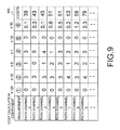
- FIG. 9 is an illustrative view illustrating a path channel candidate list.
- FIG. 10 is a diagram illustrating a display example of a path channel candidate network diagram.
- FIG. 11 is a flowchart illustrating recalculation of cost calculation coefficients.
- FIG. 12 is an illustrative view illustrating a path channel table.
- FIG. 13 is an illustrative view illustrating a path channel candidate table for recalculation ( 1 ).
- FIG. 14 is an illustrative view illustrating the path channel candidate table for recalculation ( 2 ).
- FIG. 15A is an illustrative view illustrating a channel link table.
- FIG. 15B is an illustrative view illustrating a channel node table.
- FIG. 16A is an illustrative view illustrating a channel package table.
- FIG. 16B is an illustrative view illustrating an inter-channel package table.
- FIG. 17 is an illustrative view illustrating a link redundant bandwidth table.
- FIG. 18 is an illustrative view illustrating the network of the path channel candidates (No. 2 ).
- FIG. 19A is an illustrative view illustrating the network of the path channel candidates (No. 3 ).
- FIG. 19B illustrates the redundant bandwidths for the nodes of the network of FIG. 19A .
- FIG. 1 is a configuration diagram illustrating a network system according to this embodiment.
- the network system includes a transport control server 100 that controls a network, a management terminal 120 that is coupled to the transport control server 100 and provides a screen display and a system operating means, and nodes 111 to 118 that is managed by the transport control server 100 .
- the transport control server 100 is coupled to the nodes 111 to 118 , and sets paths coupled between the respective nodes.
- path techniques there can be used a Multi-Protocol Label Switching (MPLS), an MPLS Transport Profile (MPLS-TP), a Provider Backbone Bridge Traffic Engineering (PBB-TE), and so on.
- MPLS Multi-Protocol Label Switching
- MPLS-TP MPLS Transport Profile
- PBB-TE Provider Backbone Bridge Traffic Engineering
- the number of path channels settable among 1000 nodes is about half a million even if a directionality of each path is not taken into account when it is assumed that each link between the respective nodes is one in number.
- the number of links between the respective nodes is normally two or more, and therefore the number of paths is increased.
- the number of channels between two nodes is plural, the number of path channels is further increased.
- the number of services is increased, the number of paths set on the network is also increased.
- the requirements include, for example, (1) a link disjoint (link disjoint), (2) a node disjoint (node disjoint), (3) a package disjoint (package disjoint), (4) hop number minimization, (5) the minimization of a package straddle, (6) the equalization of redundant bandwidths, and so on.
- the requirement (1) of the link disjoint is to select a channel in which a coupling link between the same nodes is not shared by an active path and a backup path.
- the requirement (2) of the node disjoint is to select a channel in which the same node is not shared by the active path and the backup path.
- the requirement (3) of the package disjoint is to select a channel in which the same package (corresponding to a network interface card) in the node is not shared by the active path and the backup path.
- the requirement (4) of the hop number minimization is to reduce the number of hops of the active path and the backup path as much as possible.
- the requirement (5) of the minimization of a package straddle is to reduce the number of times of straddling different packages within the node where the active path and the backup path are identical with each other as much as possible.
- the requirement (6) of the equalization of redundant bandwidths is to equalize the redundant bandwidths of the respective links as much as possible so that no bias occurs in the redundant bandwidths. The other appropriate requirements can be used.
- nodes 131 to 137 are coupled to each other by links.
- the node 131 is equipped with packages 141 and 142
- the node 132 is equipped with a package 143
- the node 133 is equipped with packages 144 and 145
- the node 134 is equipped with a package 146
- the node 135 is equipped with a package 147
- the node 136 is equipped with packages 148 and 149
- the node 137 is equipped with a package 150 .
- An active path 151 is represented by a solid line, and passes through the package 141 of the node 131 , the package 143 of the node 132 , the package 144 of the node 133 , the package 147 of the node 135 , and the package 148 of the node 136 .
- a backup path 152 is represented by a broken line, and passes through the package 142 of the node 131 , the package 146 of the node 134 , the package 145 of the node 133 , the package 150 of the node 137 , and the package 149 of the node 136 .
- the requirement (1) of the link disjoint means that the active path and the backup path do not pass through the link between the same nodes, and is satisfied by the configuration of FIG. 8 .
- the requirement (2) of the node disjoint means that the active path and the backup path do not pass through the same node, and as a phenomenon that violates this requirement, FIG. 8 illustrates the node 131 , the node 133 , and the node 136 .
- the requirement (3) of the package disjoint means that the active path and the backup path do not pass through the same package, and is satisfied by the configuration of FIG. 8 .
- the requirement (4) of the hop number minimization means that the number of nodes through which the active path and the backup path pass is minimized, and in FIG. 8 , the number of hops in the active path is 5, and the number of hops in the backup path is 5.
- the nodes 131 to 137 and the packages 141 to 150 are identical with those in FIG. 8 .
- the active path 151 is represented by a solid line, and passes through the package 141 of the node 131 , the package 143 of the node 132 , the package 144 of the node 133 , the package 145 of the node 133 , the package 150 of the node 137 , and the package 149 of the node 136 .
- the backup path 152 is represented by a broken line, and passes through the package 142 of the node 131 , the package 146 of the node 134 , the package 145 of the node 133 , the package 144 of the node 133 , the package 147 of the node 135 , and the package 148 of the node 136 .
- FIG. 18 illustrates a portion in which the active path straddles from the package 144 to the package 145 within the node 133 , and a portion in which the backup path straddles from the package 145 to the package 144 within the node 133 .
- the nodes 131 to 137 and the packages 141 to 150 are identical with those in FIG. 8 .
- the requirement (6) of the equalization of redundant bandwidths means that the redundant bandwidths of the respective links are equalized as much as possible so that no bias occurs in the redundant bandwidths.
- the redundant bandwidths in the link between the nodes 131 to 132 , 132 to 133 , 133 to 134 , 131 to 134 , 133 to 135 , 135 to 136 , 136 to 137 , and 133 to 137 are shown in a table as numerical values regarding the requirement.
- the redundant bandwidth is obtained by, for example, subtracting a sum of required bandwidths from a bandwidth of the link.
- FIG. 2 illustrates a configuration of the transport control server 100 according to this embodiment.
- the transport control server 100 includes, for example, a control processor 200 , a communication IF 210 , and a data storage unit 206 .
- the control processor 200 includes a graphical user interface (GUI) controller (display controller) 201 , a channel calculation unit 202 , anode setting unit 203 , a coefficient calculation unit 204 , and a cost calculation unit 205 .
- the data storage unit 206 includes a topology and channel storage unit 207 , a path channel candidate storage unit 208 , and a cost calculation coefficient storage unit 209 .
- the topology and channel storage unit 207 stores a node management table 700 , a link management table 710 , a package management table 720 , an inter-package management table 730 , a channel link table 600 , a channel node table 610 , a channel package table 620 , an inter-channel-package table 630 , and a link redundant bandwidth table 640 , which will be described later, therein.
- the path channel candidate storage unit 208 stores a path channel candidate table 400 therein.
- the cost calculation coefficient storage unit 209 stores a cost calculation coefficient table 500 therein.
- the node management table 700 , the link management table 710 , the package management table 720 , the inter-package management table 730 , the channel link table 600 , the channel node table 610 , the channel package table 620 , the inter-channel-package table 630 , the link redundant bandwidth table 640 , the path channel candidate table 400 , and the cost calculation coefficient table 500 may not be always divided into the respective storage units 207 to 209 .
- the respective tables will be described later.
- the respective table configurations may be replaced with appropriate storage areas.
- the GUI controller 201 communicates with the management terminal 120 through the communication IF 210 , and controls input and output of data.
- the channel calculation unit 202 searches the channels between the respective nodes.
- the node setting unit 203 notifies the respective nodes of setting of the selected path through the communication IF 210 .
- the coefficient calculation unit 204 recalculates a cost calculation coefficient.
- the cost calculation unit 205 calculates the costs of a path channel candidate.
- the communication IF 210 is an interface for communicating with external devices such as the management terminal 120 and the respective nodes.
- FIG. 3A illustrates the node management table 700 .
- identifiers 701 of the nodes are associated with types 702 of the nodes.
- the types 702 of the nodes indicate, for example, models or versions of the nodes.
- FIG. 3B illustrates the link management table 710 .
- identifiers 711 of the links are associated with identifiers 712 of the packages coupled with the links.
- identifiers 712 of the packages are stored, for example, two package identifiers at both ends of each link.
- FIG. 4A illustrates the package management table 720 .
- package identifiers 721 are associated with identifiers 722 of the nodes each having the package mounted therein.
- FIG. 4B illustrates the inter-package management table 730 .
- inter-package identifiers 731 are associated with related package identifiers 732 .
- Information in the respective tables of the node management table 700 , the link management table 710 , the package management table 720 , and the inter-package management table 730 can be stored in advance. For example, information may be collected from the respective nodes.
- FIG. 15A illustrates the channel link table 600 .
- the channel link table 600 stores correspondences of link identifiers 601 , flags 602 each indicating that the selected active path passes through a corresponding link, and flags 603 each indicating that the selected backup path passes through a corresponding link therein.
- FIG. 15B illustrates the channel node table 610 .
- the channel node table 610 stores correspondences of node identifiers 611 , flags 612 each indicating that the active path passes through a corresponding node, and flags 613 each indicating the backup path passes through a corresponding node therein.
- FIG. 16A illustrates the channel package table 620 .
- the channel package table 620 stores correspondences of package identifiers 621 , flags 622 each indicating that the active path passes through a corresponding package, and flags 623 each indicating that the backup path passes through a corresponding package therein.
- FIG. 16B illustrates the inter-channel-package table 630 .
- the inter-channel-package table 630 stores correspondences of inter-package identifiers 631 , flags 632 each indicating that the active path straddles between corresponding packages, and flags 633 each indicating that the backup path straddles between respective packages therein.
- the channel node table 610 In the respective flags of the active path and the backup path in the channel link table 600 , the channel node table 610 , the channel package table 620 , and the inter-channel-package table 630 , every time the active path or the backup path is selected, the previous information is cleared, and information on the selected active path or backup path can be stored.
- FIG. 17 illustrates the link redundant bandwidth table 640 .
- link identifiers 641 are associated with redundant bandwidths 641 of the links. Inverse numbers of the redundant bandwidths of the links may be stored.
- FIG. 12 illustrates a path channel table 800 .
- channel information (information on links, nodes, and packages through which channels pass through) on the active path and the backup path are associated with each other as the path channel candidates.
- FIG. 5 illustrates the path channel candidate table 400 .
- types of the requirements 401 are associated with the numbers of occurrences 402 to 409 by which the phenomena that violate the requirements occur in the respective path channel candidates, and the costs obtained on the basis of the numbers of occurrences.
- values of network elements for determining the violation of the requirements may be stored.
- the number of hops may be stored as the value of the network element.
- the respective numbers of hops in the active path and the backup path, or a sum of the numbers of hops in the active path and the backup path can be stored.
- the minimization requirement of the package straddle in the requirement (5) the number of time by which the active path and the backup path straddle the different packages within the same node may be stored as the network element.
- FIG. 6 illustrates the cost calculation coefficient table 500 .
- types of the requirements 501 and cost calculation coefficients 502 for calculating the costs of the paths are associated with each other.
- FIG. 7 illustrates a flowchart of this embodiment.
- the transport control server 100 sets topology information and the cost calculation coefficients.
- the topology information means information related to a topology of the network, which is stored in, for example, the node management table 700 , the link management table 710 , and the package management table 720 .
- the node setting unit 203 of the transport control server 100 acquires, from the nodes 111 to 118 through the communication IF 210 , the node identifiers, the node types, the link identifiers, and the package identifiers related to those nodes, and records those information in the node management table 700 , the link management table 710 , and the package management table 720 .
- control processor 200 (for example, the node setting unit 203 ) allocates an inter-package identifier to a combination of two packages within the same node, and stores the inter-package identifier and the identifier of the combined two packages in the inter-package management table 730 on the basis of the information in the package management table 720 .
- the coefficient calculation unit 204 sets a system specified value in the cost calculation coefficient table 500
- the GUI controller 201 sets the cost calculation coefficient set by using the GUI of the management terminal 120 by an operator in the cost calculation coefficient table 500 .
- Step 402 the transport control server 100 enters a parameter of a path setting request set by using the GUI of the management terminal 120 by the operator.
- the parameter of the path setting request there are, for example, an identifier of an entry side node, an identifier of an exit side node, and a bandwidth of the path.
- the GUI controller 201 receives the parameter of the path setting request input by the operator from the management terminal 120 through the communication IF 210 , and delivers the received parameter to the channel calculation unit 202 .
- the channel calculation unit 202 acquires the topology information of the network from the node management table 700 , the link management table 710 , and the package management table 720 , and calculates all the combinations of the active paths and the backup paths as the path channel candidates by searching all the channels.
- a known appropriate technique can be used for the channel search.
- the combinations of the active paths and the backup paths can be obtained by, for example, obtaining candidates of the channels between the entry side node and the exit side node, and selecting two appropriate candidates from those candidates.
- the channel calculation unit 202 stores channel information on the calculated path channel candidates in the path channel table 800 of FIG. 12 .
- the channel calculation unit 202 selects one of the path channel candidates, and calculates the links, the nodes, and the packages through which the active and the backup paths of the selected path channel candidate pass. If the active and the backup paths pass through the links, the nodes, and the packages, the channel calculation unit 202 writes flags in the channel link table 600 , the channel node table 610 , the channel package table 620 , and the inter-channel-package table 630 . If the active and the backup paths pass through the two packages stored in the inter-package management table 730 , the channel calculation unit 202 writes the flag of a corresponding inter-package identifier in the inter-channel-package table 630 .
- the channel calculation unit 202 refers to the channel link table 600 , tallies the number of links through which both of the active path and the backup path pass as the number of joints, and records the number of joints in a column of the requirement (1) of the appropriate path channel candidate of the channel candidate table 400 .
- the channel calculation unit 202 tallies the number of links where flags of both of the active path and the backup path in the channel link table 600 are on.
- the channel calculation unit 202 tallies the number of nodes and the number of packages as the number of joints in the channel node table 610 and the channel package table 620 , and records the number of joints in columns of the requirements (2) and (3) of the appropriate channel candidate in the channel candidate table 400 .
- the channel calculation unit 202 refers to the channel node table 610 , tallies the number of nodes through which the active path and the backup path pass as the number of hops, and records the number of hops in a column of the requirement (4) of the appropriate path channel candidate in the channel candidate table 400 .
- the channel calculation unit 202 refers to the inter-channel-package table 630 , tallies the number of times by which the active path and the backup path straddle the packages as the number of path straddles, and records the number of path straddles in a column of the requirement (5) of the appropriate path channel candidate in the channel candidate table 400 .
- the channel calculation unit 202 refers to the channel link table 600 and the link redundant bandwidth table 640 , tallies a sum of the inverse numbers of the redundant bandwidths of all the links through which the active path and the backup path pass, and records the tallied sum in a column of the requirement (6) of the appropriate path channel candidate in the channel candidate table 400 .
- Step 409 the channel calculation unit 202 determines whether there is another path channel candidate, or not, and if yes, the processing is advanced to Step 404 , but if no, the processing is advanced to Step 410 . For example, if all of the path channel candidates calculated in Step 403 are selected, the processing is advanced to Step 410 . On the other hand, if none of the path channel candidates is selected, the processing is returned to Step 404 , and another path channel candidate is selected.
- the cost calculation unit 205 refers to the channel candidate table 400 , and acquires numerical values of the respective requirements of the respective path channel candidates.
- the cost calculation unit 205 also refers to the cost calculation coefficient table 500 , acquires the cost calculation coefficients of the respective requirements, and records values obtained by adding numerical values resulting from multiplying the numerical values of the respective requirements by the cost calculation coefficients to all the requirements in the column “costs” in the channel candidate table 400 as the costs of the path channel candidates.
- the GUI controller 201 refers to the channel candidate table 400 , and displays a path channel candidate list 900 in a screen of the management terminal 120 .
- the node setting unit 203 may enter identification information on the candidates of the path channel selected by the operator according to the displayed list, and set the path in the node on the path channel.
- FIG. 9 illustrates the path channel candidate list 900 .
- the path channel candidates are displayed in ascending order of the costs, and the types of the requirements, the cost calculation coefficients, the numbers of occurrences of the respective path channel candidates, and the costs are displayed.
- highlight display can be conducted on the list.
- a given number of the path channel candidates may be displayed in the ascending order of the costs.
- the GUI controller 201 can acquire information on the selected path channel candidate from the node management table 700 , the link management table 710 , the package management table 720 , the inter-package management table 730 , the channel link table 600 , the channel node table 610 , the channel package table 620 , the inter-channel-package table 630 , and the link redundant bandwidth table 640 , and display a path channel candidate network diagram.
- An appropriate technique can be used in a technique for displaying the network diagram.
- FIG. 10 illustrates a display example of the path channel candidate network diagram.
- the active path is indicated by a solid line
- the backup path is indicated by a broken line.
- the redundant bandwidths of the links are also indicated on a table.
- numbers of those requirements are indicated.
- Nos. of those requirements are highlighted.
- a ranking of the path channel candidates may be improper.
- the requirement (4) of a path channel candidate 1 is 5, which is higher in ranking than a path channel candidate 2 .
- a communication delay within the path channel becomes larger, which may be improper as the path channel.
- the requirement (4) is 1, and the number of hops is smaller than the path channel candidate 1.
- the requirement (3) of the path channel candidate 2 is 2, but when there are no other path channel candidates small in the number of hops, even if the number of package disjoints in the requirement (3) is large, the operator may determine that the path channel candidate 2 is a more proper path channel.
- the cost calculation coefficients can be readjusted to correct the ranking of the path channel candidates. In order to correct the ranking of the path channel candidates, there is a method of readjusting the cost calculation coefficients described below.
- FIG. 11 illustrates a flowchart when the cost calculation coefficient is readjusted.
- Step 421 the path channel candidate (path channel candidate to be readjusted) improper in the ranking, and the path channel candidate (path channel candidate to be compared) to be compared are selected from the path channel candidates indicated in the path channel candidate list 900 by using the GUI of the management terminal 120 by the operator. Then, the transport control server 100 enters identifiers of the path channel candidate to be readjusted and the path channel candidate to be compared.
- Step 422 the transport control server 100 enters two requirements that are factors of the improper path channel candidates which are set by using the GUI of the management terminal 120 by the operator.
- a requirement higher in priority is a high priority requirement
- a requirement lower in priority is a low priority requirement.
- Step 423 the coefficient calculation unit 204 acquires, from the path channel candidate table 400 , the number of occurrences (Na) corresponding to the low priority requirement of the path channel candidates to be readjusted and the number of occurrences (Nb) corresponding to the high priority requirement of the path channel candidates to be compared.
- the coefficient calculation unit 204 acquires, from the cost calculation coefficient table 500 , a cost calculation coefficient (A) corresponding to the low priority requirement and a cost calculation coefficient (B) corresponding to the high priority requirement.
- the path channel candidate to be readjusted is a path channel 1
- the path channel candidate to be compared is a path channel 2 .
- Step 426 the coefficient calculation unit 204 updates the cost calculation coefficient corresponding to the low priority requirement in the cost calculation coefficient table 500 to a recalculated value, recalculates the costs for each of the path channels on the basis of the updated values, and also redisplays the path channel candidate list 900 .
- the coefficient calculation unit 204 may change the cost calculation coefficient B of the high priority requirement other than to change the cost calculation coefficient A of the low priority requirement.
- the coefficient calculation unit 204 acquires, from the path channel candidate table 400 , for example, the number of occurrences (Na) corresponding to the low priority requirement of the path channel candidate to be readjusted, and a cost value (Cb) of the path channel candidate to be compared.
- the coefficient calculation unit 204 may further acquire the number of occurrences (Nb) corresponding to the high priority requirement of the path channel candidate to be compared, and a cost value (Ca) of the path channel candidate to be readjusted.
- the coefficient calculation unit 204 acquires the cost calculation coefficient (A) corresponding to the low priority requirement from the cost calculation coefficient table 500 .
- the coefficient calculation unit 204 may further acquire the cost calculation coefficient (B) corresponding to the high priority requirement.
- the other steps are identical with the respective steps in FIG. 11 .
- FIG. 14 illustrates an example of a list of the recalculated cost calculation coefficients and the recalculated costs.
- the candidates of the path channels of the paired active paths and backup paths are calculated, and the number of occurrences of the phenomena that violate the respective requirements is calculated for each of the candidates of the path channels.
- the costs of the path channels are calculated according to the number of occurrences and the cost calculation coefficient, the candidates of the path channels and the number of occurrences are listed in the ascending order of the costs, and the paths are set in the above nodes.
- the costs of the path channels are calculated according to the number of occurrences, the inverse number of the redundant bandwidth, and the cost calculation coefficient.
- the number of occurrences of a value larger than a specified value may be highlighted.
- the network diagram of the selected path is displayed, and in the portion where the phenomena that violate the respective requirements occur, Nos. of those requirements may be display, and specified requirements may be highlighted in the requirements.
- the operator selects the path channel candidates and the high priority requirement and the low priority requirement from the above requirements, to thereby recalculate the cost calculation coefficient, and redisplay the list.
- the specified priority requirements are set so that a product of the high priority requirement and the cost calculation coefficient is identical with a product of the low priority requirement and the cost calculation coefficient.
- the present invention can be applied to, for example, a network system in which candidates of path channels are automatically calculated.
Landscapes
- Engineering & Computer Science (AREA)
- Computer Networks & Wireless Communication (AREA)
- Signal Processing (AREA)
- Data Exchanges In Wide-Area Networks (AREA)
Abstract
A passage channel is calculated by taking into account a plurality of requirements having different importance degrees. A channel calculation unit (202) of a transport control server (100) calculates a plurality of passage channel candidates with respect to a passage setting request wherein an active passage candidate and a standby passage candidate are paired in the passage channel candidate; and calculates the occurrence number of phenomena that violate a predetermined requirement relating an operation of the active passage and the standby passage, or a value of a network element for determining whether the requirement is violated, with respect to each passage channel candidate. A cost calculation unit (205) calculates the cost of a passage channel from the calculated number of occurrence, network element value, and a predetermined cost calculation coefficient corresponding to the requirement. A GUI control unit (display control unit) 201 displays identification information of the passage channel candidate, the number of occurrences or the network element value, and the cost, as a list on, for example, a management terminal.
Description
Japan Priority Application 2009-280065, filed Dec. 10, 2009 including the specification, drawings, claims and abstract, is incorporated herein by reference in its entirety. This application is a Continuation of U.S. application Ser. No. 13/501,235 (National Stage of PCT/JP2010/065197), filed Jun. 22, 2012, incorporated herein by reference in its entirety.
The present invention relates to a transport control server (TCS), a transport control system, and a transport control method, and more particularly to a transport control server, a transport control system, and a transport control method in which the number of occurrences of a phenomenon that violates a requirement designated by a network operator is counted with respect to a combination of an active path and a backup path, and path channel candidates are ordered and displayed, to thereby facilitate a selection of an optimum path channel by the operator.
In a conventional transport control system, various techniques for automatically designing a path channel have been used in setting and controlling a path such as multi-protocol label switching (MPLS). For example, JP-A-2008-85642 (Patent Literature 1) provides a technique by which when a network is divided into plural areas, a path crossing the areas is efficiently set. Also, JP-A-2008-54211 (Patent Literature 2) enables an LSP channel calculation which minimizes the number of links configuring a label switch path (LSP). Also, JP-A-2007-166433 (Patent Literature 3) sets a channel by easing conditions even in any network environments, and even under circumstances where an alternative channel is not found. Also, JP-A-2007-158818 (Patent Literature 4) provides a technique by which the number of paths caused by a channel change is reduced during recalculation while achieving an effective use of network resources. Also, JP-A-2007-74312 (Patent Literature 5) enables a bypass for P2MP TE LSP due to P2MP TE LSP to be set.
[Patent Literature 1] JP-A-2008-85642
[Patent Literature 2] JP-A-2008-54211
[Patent Literature 3] JP-A-2007-166433
[Patent Literature 4] JP-A-2007-158818
[Patent Literature 5] JP-A-2007-74312
In the conventional system, only a single requirement is considered in calculating a path channel, and plural requirements are not dealt with. Also, respective conventional systems meet different requirements. However, because a technique for calculating the path channel is different depending on the respective conventional systems, a uniform technique corresponding to all the requirements is not provided. Further, those conventional systems provide no means for allowing a network operator to select a final path channel from plural path channel candidates while evaluating adaptability to the plural requirements.
On the other hand, there are various requirements designated by the network operator, and there is no conventional system that calculates an optimum path channel taking all of those requirements into account. In the conventional system, there are methods for calculating the path channel on the basis of the single requirement, but there is no calculating method taking the plural requirements into account. Also, there is provided no means for allowing the network operator to visually compare the plural path channel candidates with each other to confirm that a path channel candidate calculated as a result of taking the plural requirements into account is optimum without a doubt.
In view of the above, one object of the present invention is to calculate a path channel taking plural requirements different in the degree of importance into account. Another object of the present invention is to allow a network operator to select a final path channel from plural path channel candidates while evaluating the adaptability to plural requirements.
According to the present invention, there are provided a transport control server, a network system, and a transport control method in which the number of occurrences of a phenomenon that violates a requirement designated by a network operator is counted with respect to a combination of an active path and a backup path, and path channel candidates are ordered and displayed, to thereby facilitate a selection of an optimum path by the operator.
According to the first solving means of the present invention, there is provided a transport control server in a network system having a plurality of nodes and the transport control server, the transport control server comprising:
a channel calculation unit that calculates a plurality of candidates of path channels in each of which a candidate of an active path and a candidate of a backup path are paired with respect to a request for path setting, and calculates the number of occurrences of phenomena that violate one or a plurality of predetermined requirements for operation of the active path and the backup path, or a value of a network element for determining whether to violate the requirements or not, for each of the candidates of the path channels;
a cost calculation unit that calculates a cost of the path channel according to the calculated number of occurrences or the calculated value of the network element, and predetermined cost calculation coefficients corresponding to the requirements; and
a display controller that displays identification information on the candidates of the path channels, the number of occurrences or the value of the network element, and the costs, as a list.
According to the second solving means of the present invention, there is provided a transport control system, comprising:
a transport control server that manages a plurality of nodes; and
a management terminal that displays information from the transport control server,
wherein the transport control server comprising:
a channel calculation unit that calculates a plurality of candidates of path channels in each of which a candidate of an active path and a candidate of a backup path are paired with respect to a request for path setting, and calculates the number of occurrences of phenomena that violate one or a plurality of predetermined requirements for operation of the active path and the backup path, or a value of a network element for determining whether to violate the requirements or not, for each of the candidates of the path channels;
a cost calculation unit that calculates a cost of the path channel according to the calculated number of occurrences or the calculated value of the network element, and predetermined cost calculation coefficients corresponding to the requirements; and
a display controller that displays identification information on the candidates of the path channels, the number of occurrences or the value of the network element, and the costs, to the management terminal as a list.
According to the third solving means of the invention, there is provided a transport control method in a network system having a plurality of nodes and the transport control server, the transport control method including steps of:
calculating a plurality of candidates of path channels in each of which a candidate of an active path and a candidate of a backup path are paired with respect to a request for path setting, and calculating the number of occurrences of phenomena that violate one or a plurality of predetermined requirements for operation of the active path and the backup path, or a value of a network element for determining whether to violate the requirements or not, for each of the candidates of the path channels;
calculating a cost of the path channel according to the calculated number of occurrences or the calculated value of the network element, and predetermined cost calculation coefficients corresponding to the requirements; and
displaying identification information on the candidates of the path channels, the number of occurrences or the value of the network element, and the costs, as a list.
It is possible, by the present invention, to calculate a path channel taking plural requirements different in the degree of importance into account. Also, it is possible, by the present invention, to allow a network operator to select a final path channel from plural path channel candidates while evaluating the adaptability to plural requirements.
Hereinafter, a network system according to embodiments of the present invention will be described in detail with reference to the drawings. In the following description, identical reference numerals denote the same or similar parts.
The network system includes a transport control server 100 that controls a network, a management terminal 120 that is coupled to the transport control server 100 and provides a screen display and a system operating means, and nodes 111 to 118 that is managed by the transport control server 100.
The transport control server 100 is coupled to the nodes 111 to 118, and sets paths coupled between the respective nodes. As examples of path techniques, there can be used a Multi-Protocol Label Switching (MPLS), an MPLS Transport Profile (MPLS-TP), a Provider Backbone Bridge Traffic Engineering (PBB-TE), and so on. The paths are set for VPNs accommodated in the respective nodes, and services of sounds or moving pictures, and therefore set between the respective nodes.
As the number of services and the number of nodes are increased, the number of paths is also increased. Therefore, the costs required for designing and managing path channels become enormous. As an example, the number of path channels settable among 1000 nodes is about half a million even if a directionality of each path is not taken into account when it is assumed that each link between the respective nodes is one in number. The number of links between the respective nodes is normally two or more, and therefore the number of paths is increased. Further, when the number of channels between two nodes is plural, the number of path channels is further increased. Also, as the number of services is increased, the number of paths set on the network is also increased. Hence, for the purpose of selecting an optimum path channel from an enormous number of path channels while the paths already set on the network are taken into account, it is essential to automatize a path channel calculation.
Now, requirements designated by the network operator will be described. The requirements include, for example, (1) a link disjoint (link disjoint), (2) a node disjoint (node disjoint), (3) a package disjoint (package disjoint), (4) hop number minimization, (5) the minimization of a package straddle, (6) the equalization of redundant bandwidths, and so on. The requirement (1) of the link disjoint is to select a channel in which a coupling link between the same nodes is not shared by an active path and a backup path. Also, the requirement (2) of the node disjoint is to select a channel in which the same node is not shared by the active path and the backup path. The requirement (3) of the package disjoint is to select a channel in which the same package (corresponding to a network interface card) in the node is not shared by the active path and the backup path. The requirement (4) of the hop number minimization is to reduce the number of hops of the active path and the backup path as much as possible. The requirement (5) of the minimization of a package straddle is to reduce the number of times of straddling different packages within the node where the active path and the backup path are identical with each other as much as possible. The requirement (6) of the equalization of redundant bandwidths is to equalize the redundant bandwidths of the respective links as much as possible so that no bias occurs in the redundant bandwidths. The other appropriate requirements can be used.
Some of those requirements will be described with reference to FIG. 8 . In an example of FIG. 8 , nodes 131 to 137 are coupled to each other by links. The node 131 is equipped with packages 141 and 142, the node 132 is equipped with a package 143, the node 133 is equipped with packages 144 and 145, the node 134 is equipped with a package 146, the node 135 is equipped with a package 147, the node 136 is equipped with packages 148 and 149, and the node 137 is equipped with a package 150.
An active path 151 is represented by a solid line, and passes through the package 141 of the node 131, the package 143 of the node 132, the package 144 of the node 133, the package 147 of the node 135, and the package 148 of the node 136. On the other hand, a backup path 152 is represented by a broken line, and passes through the package 142 of the node 131, the package 146 of the node 134, the package 145 of the node 133, the package 150 of the node 137, and the package 149 of the node 136.
The requirement (1) of the link disjoint means that the active path and the backup path do not pass through the link between the same nodes, and is satisfied by the configuration of FIG. 8 . The requirement (2) of the node disjoint means that the active path and the backup path do not pass through the same node, and as a phenomenon that violates this requirement, FIG. 8 illustrates the node 131, the node 133, and the node 136. The requirement (3) of the package disjoint means that the active path and the backup path do not pass through the same package, and is satisfied by the configuration of FIG. 8. The requirement (4) of the hop number minimization means that the number of nodes through which the active path and the backup path pass is minimized, and in FIG. 8 , the number of hops in the active path is 5, and the number of hops in the backup path is 5.
Another requirement will be described with reference to FIG. 18 . The nodes 131 to 137 and the packages 141 to 150 are identical with those in FIG. 8 . The active path 151 is represented by a solid line, and passes through the package 141 of the node 131, the package 143 of the node 132, the package 144 of the node 133, the package 145 of the node 133, the package 150 of the node 137, and the package 149 of the node 136. On the other hand, the backup path 152 is represented by a broken line, and passes through the package 142 of the node 131, the package 146 of the node 134, the package 145 of the node 133, the package 144 of the node 133, the package 147 of the node 135, and the package 148 of the node 136.
The requirement (5) of the minimization of the package straddle means that the number of times by which the active path or the backup path straddles the different packages within the same node is minimized. As a phenomenon that violates this requirement, FIG. 18 illustrates a portion in which the active path straddles from the package 144 to the package 145 within the node 133, and a portion in which the backup path straddles from the package 145 to the package 144 within the node 133.
Still another requirement will be described with reference to FIGS. 19A and 19B . The nodes 131 to 137 and the packages 141 to 150 are identical with those in FIG. 8 . The requirement (6) of the equalization of redundant bandwidths means that the redundant bandwidths of the respective links are equalized as much as possible so that no bias occurs in the redundant bandwidths. The redundant bandwidths in the link between the nodes 131 to 132, 132 to 133, 133 to 134, 131 to 134, 133 to 135, 135 to 136, 136 to 137, and 133 to 137 are shown in a table as numerical values regarding the requirement. In this example, the redundant bandwidth is obtained by, for example, subtracting a sum of required bandwidths from a bandwidth of the link.
The transport control server 100 includes, for example, a control processor 200, a communication IF 210, and a data storage unit 206. The control processor 200 includes a graphical user interface (GUI) controller (display controller) 201, a channel calculation unit 202, anode setting unit 203, a coefficient calculation unit 204, and a cost calculation unit 205. The data storage unit 206 includes a topology and channel storage unit 207, a path channel candidate storage unit 208, and a cost calculation coefficient storage unit 209.
The topology and channel storage unit 207 stores a node management table 700, a link management table 710, a package management table 720, an inter-package management table 730, a channel link table 600, a channel node table 610, a channel package table 620, an inter-channel-package table 630, and a link redundant bandwidth table 640, which will be described later, therein. Also, the path channel candidate storage unit 208 stores a path channel candidate table 400 therein. The cost calculation coefficient storage unit 209 stores a cost calculation coefficient table 500 therein. The node management table 700, the link management table 710, the package management table 720, the inter-package management table 730, the channel link table 600, the channel node table 610, the channel package table 620, the inter-channel-package table 630, the link redundant bandwidth table 640, the path channel candidate table 400, and the cost calculation coefficient table 500 may not be always divided into the respective storage units 207 to 209. The respective tables will be described later. The respective table configurations may be replaced with appropriate storage areas.
The GUI controller 201 communicates with the management terminal 120 through the communication IF 210, and controls input and output of data. The channel calculation unit 202 searches the channels between the respective nodes. The node setting unit 203 notifies the respective nodes of setting of the selected path through the communication IF 210. The coefficient calculation unit 204 recalculates a cost calculation coefficient. The cost calculation unit 205 calculates the costs of a path channel candidate. The communication IF 210 is an interface for communicating with external devices such as the management terminal 120 and the respective nodes.
In the minimizing requirements such as the requirements (4) and (5), values of network elements for determining the violation of the requirements may be stored. For example, in the hop number minimization requirement in the requirement (4), the number of hops may be stored as the value of the network element. For example, the respective numbers of hops in the active path and the backup path, or a sum of the numbers of hops in the active path and the backup path can be stored. Also, in the minimization requirement of the package straddle in the requirement (5), the number of time by which the active path and the backup path straddle the different packages within the same node may be stored as the network element.
In Step 401, the transport control server 100 sets topology information and the cost calculation coefficients. The topology information means information related to a topology of the network, which is stored in, for example, the node management table 700, the link management table 710, and the package management table 720. The node setting unit 203 of the transport control server 100 acquires, from the nodes 111 to 118 through the communication IF 210, the node identifiers, the node types, the link identifiers, and the package identifiers related to those nodes, and records those information in the node management table 700, the link management table 710, and the package management table 720. Also, the control processor 200 (for example, the node setting unit 203) allocates an inter-package identifier to a combination of two packages within the same node, and stores the inter-package identifier and the identifier of the combined two packages in the inter-package management table 730 on the basis of the information in the package management table 720. Also, for the cost calculation coefficients, for example, the coefficient calculation unit 204 sets a system specified value in the cost calculation coefficient table 500, or the GUI controller 201 sets the cost calculation coefficient set by using the GUI of the management terminal 120 by an operator in the cost calculation coefficient table 500.
In Step 402, the transport control server 100 enters a parameter of a path setting request set by using the GUI of the management terminal 120 by the operator. As the parameter of the path setting request, there are, for example, an identifier of an entry side node, an identifier of an exit side node, and a bandwidth of the path. The GUI controller 201 receives the parameter of the path setting request input by the operator from the management terminal 120 through the communication IF 210, and delivers the received parameter to the channel calculation unit 202.
In Step 403, the channel calculation unit 202 acquires the topology information of the network from the node management table 700, the link management table 710, and the package management table 720, and calculates all the combinations of the active paths and the backup paths as the path channel candidates by searching all the channels. A known appropriate technique can be used for the channel search. The combinations of the active paths and the backup paths can be obtained by, for example, obtaining candidates of the channels between the entry side node and the exit side node, and selecting two appropriate candidates from those candidates. The channel calculation unit 202 stores channel information on the calculated path channel candidates in the path channel table 800 of FIG. 12 .
In Step 404, the channel calculation unit 202 selects one of the path channel candidates, and calculates the links, the nodes, and the packages through which the active and the backup paths of the selected path channel candidate pass. If the active and the backup paths pass through the links, the nodes, and the packages, the channel calculation unit 202 writes flags in the channel link table 600, the channel node table 610, the channel package table 620, and the inter-channel-package table 630. If the active and the backup paths pass through the two packages stored in the inter-package management table 730, the channel calculation unit 202 writes the flag of a corresponding inter-package identifier in the inter-channel-package table 630.
In Step 405, the channel calculation unit 202 refers to the channel link table 600, tallies the number of links through which both of the active path and the backup path pass as the number of joints, and records the number of joints in a column of the requirement (1) of the appropriate path channel candidate of the channel candidate table 400. For example, the channel calculation unit 202 tallies the number of links where flags of both of the active path and the backup path in the channel link table 600 are on. Similarly, the channel calculation unit 202 tallies the number of nodes and the number of packages as the number of joints in the channel node table 610 and the channel package table 620, and records the number of joints in columns of the requirements (2) and (3) of the appropriate channel candidate in the channel candidate table 400. In Step 406, the channel calculation unit 202 refers to the channel node table 610, tallies the number of nodes through which the active path and the backup path pass as the number of hops, and records the number of hops in a column of the requirement (4) of the appropriate path channel candidate in the channel candidate table 400. In Step 407, the channel calculation unit 202 refers to the inter-channel-package table 630, tallies the number of times by which the active path and the backup path straddle the packages as the number of path straddles, and records the number of path straddles in a column of the requirement (5) of the appropriate path channel candidate in the channel candidate table 400. In Step 408, the channel calculation unit 202 refers to the channel link table 600 and the link redundant bandwidth table 640, tallies a sum of the inverse numbers of the redundant bandwidths of all the links through which the active path and the backup path pass, and records the tallied sum in a column of the requirement (6) of the appropriate path channel candidate in the channel candidate table 400.
In Step 409, the channel calculation unit 202 determines whether there is another path channel candidate, or not, and if yes, the processing is advanced to Step 404, but if no, the processing is advanced to Step 410. For example, if all of the path channel candidates calculated in Step 403 are selected, the processing is advanced to Step 410. On the other hand, if none of the path channel candidates is selected, the processing is returned to Step 404, and another path channel candidate is selected.
In Step 410, the cost calculation unit 205 refers to the channel candidate table 400, and acquires numerical values of the respective requirements of the respective path channel candidates. The cost calculation unit 205 also refers to the cost calculation coefficient table 500, acquires the cost calculation coefficients of the respective requirements, and records values obtained by adding numerical values resulting from multiplying the numerical values of the respective requirements by the cost calculation coefficients to all the requirements in the column “costs” in the channel candidate table 400 as the costs of the path channel candidates. In Step 411, the GUI controller 201 refers to the channel candidate table 400, and displays a path channel candidate list 900 in a screen of the management terminal 120. The node setting unit 203 may enter identification information on the candidates of the path channel selected by the operator according to the displayed list, and set the path in the node on the path channel.
When the operator selects one of the path channel candidates in the path channel candidate list 900 by using the GUI of the management terminal 120, the GUI controller 201 can acquire information on the selected path channel candidate from the node management table 700, the link management table 710, the package management table 720, the inter-package management table 730, the channel link table 600, the channel node table 610, the channel package table 620, the inter-channel-package table 630, and the link redundant bandwidth table 640, and display a path channel candidate network diagram. An appropriate technique can be used in a technique for displaying the network diagram.
In the path channel candidate network diagram, for example, the active path is indicated by a solid line, and the backup path is indicated by a broken line. Also, the redundant bandwidths of the links are also indicated on a table. Also, in portions where the phenomena that violate the respective requirements occur, numbers of those requirements are indicated. Further, in the specified requirements designated as the specified values of the system, Nos. of those requirements ((3) and (5) in this case) are highlighted.
(Adjustment of Cost Calculation Coefficients)
In the path channel candidate list 900 of FIG. 9 , a ranking of the path channel candidates may be improper. For example, in the path channel candidate list 900 of FIG. 13 , the requirement (4) of a path channel candidate 1 is 5, which is higher in ranking than a path channel candidate 2. However, as the number of hops in the requirement (4) is larger, a communication delay within the path channel becomes larger, which may be improper as the path channel. On the other hand, in the path channel candidate 2, the requirement (4) is 1, and the number of hops is smaller than the path channel candidate 1. Also, the requirement (3) of the path channel candidate 2 is 2, but when there are no other path channel candidates small in the number of hops, even if the number of package disjoints in the requirement (3) is large, the operator may determine that the path channel candidate 2 is a more proper path channel. Thus, when the ranking of the path channel candidates is improper, the cost calculation coefficients can be readjusted to correct the ranking of the path channel candidates. In order to correct the ranking of the path channel candidates, there is a method of readjusting the cost calculation coefficients described below.
In Step 421, the path channel candidate (path channel candidate to be readjusted) improper in the ranking, and the path channel candidate (path channel candidate to be compared) to be compared are selected from the path channel candidates indicated in the path channel candidate list 900 by using the GUI of the management terminal 120 by the operator. Then, the transport control server 100 enters identifiers of the path channel candidate to be readjusted and the path channel candidate to be compared.
In Step 422, the transport control server 100 enters two requirements that are factors of the improper path channel candidates which are set by using the GUI of the management terminal 120 by the operator. In this situation, in the two requirements, a requirement higher in priority is a high priority requirement, and a requirement lower in priority is a low priority requirement.
In Step 423, the coefficient calculation unit 204 acquires, from the path channel candidate table 400, the number of occurrences (Na) corresponding to the low priority requirement of the path channel candidates to be readjusted and the number of occurrences (Nb) corresponding to the high priority requirement of the path channel candidates to be compared.
In Step 424, the coefficient calculation unit 204 acquires, from the cost calculation coefficient table 500, a cost calculation coefficient (A) corresponding to the low priority requirement and a cost calculation coefficient (B) corresponding to the high priority requirement. In an example illustrated in FIG. 13 , the path channel candidate to be readjusted is a path channel 1, and the path channel candidate to be compared is a path channel 2. In this example, A=1, B=5, Na=5, and Nb=2.
In Step 425, the coefficient calculation unit 204 recalculates the cost calculation coefficient A so as to satisfy A×Na=B×Nb. In Step 426, the coefficient calculation unit 204 updates the cost calculation coefficient corresponding to the low priority requirement in the cost calculation coefficient table 500 to a recalculated value, recalculates the costs for each of the path channels on the basis of the updated values, and also redisplays the path channel candidate list 900. The coefficient calculation unit 204 may change the cost calculation coefficient B of the high priority requirement other than to change the cost calculation coefficient A of the low priority requirement.
Another method of correcting the ranking of the path channel candidates will be described below. In the above-mentioned Step 423, the coefficient calculation unit 204 acquires, from the path channel candidate table 400, for example, the number of occurrences (Na) corresponding to the low priority requirement of the path channel candidate to be readjusted, and a cost value (Cb) of the path channel candidate to be compared. The coefficient calculation unit 204 may further acquire the number of occurrences (Nb) corresponding to the high priority requirement of the path channel candidate to be compared, and a cost value (Ca) of the path channel candidate to be readjusted.
In Step 424, the coefficient calculation unit 204 acquires the cost calculation coefficient (A) corresponding to the low priority requirement from the cost calculation coefficient table 500. The coefficient calculation unit 204 may further acquire the cost calculation coefficient (B) corresponding to the high priority requirement. In an example of FIG. 13 , Ca=40 and Cb=41 are satisfied.
In Step 425, the coefficient calculation unit 204 changes the cost calculation coefficient A, and recalculates the cost calculation coefficient A so that a cost (Ca′=Na×A′) of the path channel candidate to be readjusted and the cost (Cb) of the path channel candidate to be compared become identical with each other (Ca′=Cb) by a changed cost calculation coefficient A′. The other steps are identical with the respective steps in FIG. 11 . FIG. 14 illustrates an example of a list of the recalculated cost calculation coefficients and the recalculated costs.
(Configuration Example of Transport Control System)
In the transport control system according to this embodiment, for example, in a communication network, in response to a request for path setting, the candidates of the path channels of the paired active paths and backup paths are calculated, and the number of occurrences of the phenomena that violate the respective requirements is calculated for each of the candidates of the path channels. Then, the costs of the path channels are calculated according to the number of occurrences and the cost calculation coefficient, the candidates of the path channels and the number of occurrences are listed in the ascending order of the costs, and the paths are set in the above nodes.
In calculation of the costs of the path channel, the costs of the path channels are calculated according to the number of occurrences, the inverse number of the redundant bandwidth, and the cost calculation coefficient. In the list, the number of occurrences of a value larger than a specified value may be highlighted. Also, in the list, when the operator selects the candidate of the path channels, the network diagram of the selected path is displayed, and in the portion where the phenomena that violate the respective requirements occur, Nos. of those requirements may be display, and specified requirements may be highlighted in the requirements.
In the above list, the operator selects the path channel candidates and the high priority requirement and the low priority requirement from the above requirements, to thereby recalculate the cost calculation coefficient, and redisplay the list. In recalculation of the cost calculation coefficient, the specified priority requirements are set so that a product of the high priority requirement and the cost calculation coefficient is identical with a product of the low priority requirement and the cost calculation coefficient.
The present invention can be applied to, for example, a network system in which candidates of path channels are automatically calculated.
- 100: transport control server
- 111 to 118: nodes
- 120: management terminal
- 201: GUI controller
- 202: channel calculation unit
- 203: node setting unit
- 204: coefficient calculation unit
- 205: cost calculation unit
- 206: data storage unit
- 207: topology and channel storage unit
- 208: path channel candidate storage unit
- 209: cost calculation coefficient storage unit
- 210: communication IF
- 700: node management table
- 710: link management table
- 720: package management table
- 730: inter-package management table
- 600: channel link table
- 610: channel node table
- 620: channel package table
- 630: inter-channel-package table
- 640: link redundant bandwidth table
Claims (5)
1. A transport control server coupled to a plurality of nodes in a network, the transport control server comprising:
at least one processor coupled to a storage device, the at least one processor configured to:
receive designation of a plurality of requirements for operation;
select a group of candidates of path channels to be determined for the plurality of requirements, among paths that are among the plurality of nodes in the network and that are obtained by path search responsive to a request for path setting;
determine a number of phenomenon according to any of the requirements or a value of network elements regarding any of the requirements, for each of the plurality of candidates of path channels of the selected group, for each of the designated requirements, wherein the phenomenon comprises at least one of a link disjoint, a node disjoint, or a package disjoint, and wherein the value of network elements comprises at least one of a number of hops, a number of package straddles, or redundant bandwidths;
provide the determined number of phenomenon or the determined value of network elements for each of the requirements in distinguishable state;
receive designation of a coefficient which is given for each of the requirements;
determine cost for each of the plurality of candidates of path channels of the group based on (i) the coefficient and (ii) the number of phenomenon or the value of network elements determined for each of the requirements;
determine a rank of the plurality of candidates of path channels of the group using the determined cost;
receive a correction of the coefficient after determining the rank of the plurality of candidates of path channels of the group using the designated coefficient;
re-determine the cost by using the corrected coefficient where the corrected coefficient is designated; and
pair a candidate of an active path with a candidate of a backup path, both are selected among the paths obtained by the path search, when selecting the group of candidates of path channels.
2. The transport control server according to claim 1 , wherein the at least one processor is further configured to provide an order of the plurality of candidates of path channels of the group in distinguishable state for each requirement, based on the determined number of phenomenon or the determined value of network elements.
3. The transport control server according to claim 2 , wherein the at least one processor is further configured to
provide the rank of the plurality of candidates of path channels of the group.
4. The transport control server according to claim 1 , wherein the at least one processor is further configured to
display the determined number of phenomenon or the determined value of network elements, for each of the plurality of candidates of path channels of the group, for each of the requirements.
5. The transport control server according to claim 3 , wherein the at least one processor is further configured to
display the determined number of phenomenon or the determined value of network elements, and the cost, by corresponding each other, for each of the plurality of candidates of path channels of the group, for each of the requirements.
Priority Applications (1)
| Application Number | Priority Date | Filing Date | Title |
|---|---|---|---|
| US14/684,587 US9537765B2 (en) | 2009-12-10 | 2015-04-13 | Transport control server, transport control system, and transport control method |
Applications Claiming Priority (5)
| Application Number | Priority Date | Filing Date | Title |
|---|---|---|---|
| JP2009-280065 | 2009-12-10 | ||
| JP2009280065 | 2009-12-10 | ||
| PCT/JP2010/065197 WO2011070830A1 (en) | 2009-12-10 | 2010-09-06 | Transport control server, transport control system, and transport control method |
| US201213501235A | 2012-06-22 | 2012-06-22 | |
| US14/684,587 US9537765B2 (en) | 2009-12-10 | 2015-04-13 | Transport control server, transport control system, and transport control method |
Related Parent Applications (2)
| Application Number | Title | Priority Date | Filing Date |
|---|---|---|---|
| US13/501,235 Continuation US20120263062A1 (en) | 2009-12-10 | 2010-09-06 | Transport control server, transport control system, and transport control method |
| PCT/JP2010/065197 Continuation WO2011070830A1 (en) | 2009-12-10 | 2010-09-06 | Transport control server, transport control system, and transport control method |
Publications (2)
| Publication Number | Publication Date |
|---|---|
| US20160142298A1 US20160142298A1 (en) | 2016-05-19 |
| US9537765B2 true US9537765B2 (en) | 2017-01-03 |
Family
ID=44145384
Family Applications (2)
| Application Number | Title | Priority Date | Filing Date |
|---|---|---|---|
| US13/501,235 Abandoned US20120263062A1 (en) | 2009-12-10 | 2010-09-06 | Transport control server, transport control system, and transport control method |
| US14/684,587 Expired - Fee Related US9537765B2 (en) | 2009-12-10 | 2015-04-13 | Transport control server, transport control system, and transport control method |
Family Applications Before (1)
| Application Number | Title | Priority Date | Filing Date |
|---|---|---|---|
| US13/501,235 Abandoned US20120263062A1 (en) | 2009-12-10 | 2010-09-06 | Transport control server, transport control system, and transport control method |
Country Status (3)
| Country | Link |
|---|---|
| US (2) | US20120263062A1 (en) |
| JP (1) | JP5443511B2 (en) |
| WO (1) | WO2011070830A1 (en) |
Families Citing this family (2)
| Publication number | Priority date | Publication date | Assignee | Title |
|---|---|---|---|---|
| WO2012137501A1 (en) * | 2011-04-04 | 2012-10-11 | Nec Corporation | Control server, network control method, and program |
| JP5919046B2 (en) | 2012-03-13 | 2016-05-18 | 株式会社日立製作所 | Path calculation method |
Citations (16)
| Publication number | Priority date | Publication date | Assignee | Title |
|---|---|---|---|---|
| US6519231B1 (en) | 1999-01-12 | 2003-02-11 | Nortel Networks Limited | Method and apparatus providing a spanning tree protocol for a data communications network having a multi-link trunk |
| JP2003318955A (en) | 2002-04-19 | 2003-11-07 | Nippon Telegr & Teleph Corp <Ntt> | Method for providing path setting service, router, and authentication accounting server |
| US20040042473A1 (en) | 2002-08-28 | 2004-03-04 | Park Hye Kyeong | Method for providing QoS (quality of service) - guaranteeing multi-path and method for providing disjoint path using the same |
| US20040151130A1 (en) | 1999-09-27 | 2004-08-05 | Nortel Networks Limited | State information and routing table updates in large scale data networks |
| JP2005101833A (en) | 2003-09-24 | 2005-04-14 | Nec Corp | Route designing server |
| JP2006135686A (en) | 2004-11-05 | 2006-05-25 | Nippon Telegr & Teleph Corp <Ntt> | Method and device for network failure recovery management |
| JP2007074312A (en) | 2005-09-06 | 2007-03-22 | Nippon Telegr & Teleph Corp <Ntt> | Bypass path calculating device and program, bypass path calculating server and router, and bypass path calculating method and system |
| JP2007158818A (en) | 2005-12-06 | 2007-06-21 | Nippon Telegr & Teleph Corp <Ntt> | Route setting method and route setting device |
| JP2007166433A (en) | 2005-12-15 | 2007-06-28 | Nippon Telegr & Teleph Corp <Ntt> | Alternate route calculation method and apparatus, alternate route calculation server, alternate route calculation router, and alternate route calculation program |
| JP2007194719A (en) | 2006-01-17 | 2007-08-02 | Nippon Telegr & Teleph Corp <Ntt> | Backup path routing management system on a plurality of layer networks |
| US20070280117A1 (en) * | 2006-06-02 | 2007-12-06 | Fabio Katz | Smart ethernet edge networking system |
| JP2008054211A (en) | 2006-08-28 | 2008-03-06 | Nippon Telegr & Teleph Corp <Ntt> | Routing method, apparatus and program |
| US20080075008A1 (en) | 2006-09-27 | 2008-03-27 | Fujitsu Limited | Transmission apparatus and path establishing method |
| US20090285101A1 (en) * | 2008-05-15 | 2009-11-19 | Wenhu Lu | Method and Apparatus for Dynamically Runtime Adjustable Path Computation |
| US20090285208A1 (en) * | 2008-05-15 | 2009-11-19 | Wenhu Lu | Method and Apparatus for Performing a Constraint Shortest Path First Computation |
| US20100061264A1 (en) * | 2008-09-11 | 2010-03-11 | Verizon Business Network Services Inc. | Method and system for identifying network paths |
-
2010
- 2010-09-06 JP JP2011545109A patent/JP5443511B2/en not_active Expired - Fee Related
- 2010-09-06 WO PCT/JP2010/065197 patent/WO2011070830A1/en active Application Filing
- 2010-09-06 US US13/501,235 patent/US20120263062A1/en not_active Abandoned
-
2015
- 2015-04-13 US US14/684,587 patent/US9537765B2/en not_active Expired - Fee Related
Patent Citations (17)
| Publication number | Priority date | Publication date | Assignee | Title |
|---|---|---|---|---|
| US6519231B1 (en) | 1999-01-12 | 2003-02-11 | Nortel Networks Limited | Method and apparatus providing a spanning tree protocol for a data communications network having a multi-link trunk |
| US20040151130A1 (en) | 1999-09-27 | 2004-08-05 | Nortel Networks Limited | State information and routing table updates in large scale data networks |
| JP2003318955A (en) | 2002-04-19 | 2003-11-07 | Nippon Telegr & Teleph Corp <Ntt> | Method for providing path setting service, router, and authentication accounting server |
| US20040042473A1 (en) | 2002-08-28 | 2004-03-04 | Park Hye Kyeong | Method for providing QoS (quality of service) - guaranteeing multi-path and method for providing disjoint path using the same |
| JP2005101833A (en) | 2003-09-24 | 2005-04-14 | Nec Corp | Route designing server |
| JP2006135686A (en) | 2004-11-05 | 2006-05-25 | Nippon Telegr & Teleph Corp <Ntt> | Method and device for network failure recovery management |
| JP2007074312A (en) | 2005-09-06 | 2007-03-22 | Nippon Telegr & Teleph Corp <Ntt> | Bypass path calculating device and program, bypass path calculating server and router, and bypass path calculating method and system |
| JP2007158818A (en) | 2005-12-06 | 2007-06-21 | Nippon Telegr & Teleph Corp <Ntt> | Route setting method and route setting device |
| JP2007166433A (en) | 2005-12-15 | 2007-06-28 | Nippon Telegr & Teleph Corp <Ntt> | Alternate route calculation method and apparatus, alternate route calculation server, alternate route calculation router, and alternate route calculation program |
| JP2007194719A (en) | 2006-01-17 | 2007-08-02 | Nippon Telegr & Teleph Corp <Ntt> | Backup path routing management system on a plurality of layer networks |
| US20070280117A1 (en) * | 2006-06-02 | 2007-12-06 | Fabio Katz | Smart ethernet edge networking system |
| JP2008054211A (en) | 2006-08-28 | 2008-03-06 | Nippon Telegr & Teleph Corp <Ntt> | Routing method, apparatus and program |
| US20080075008A1 (en) | 2006-09-27 | 2008-03-27 | Fujitsu Limited | Transmission apparatus and path establishing method |
| JP2008085642A (en) | 2006-09-27 | 2008-04-10 | Fujitsu Ltd | Transmitting device and path setting method |
| US20090285101A1 (en) * | 2008-05-15 | 2009-11-19 | Wenhu Lu | Method and Apparatus for Dynamically Runtime Adjustable Path Computation |
| US20090285208A1 (en) * | 2008-05-15 | 2009-11-19 | Wenhu Lu | Method and Apparatus for Performing a Constraint Shortest Path First Computation |
| US20100061264A1 (en) * | 2008-09-11 | 2010-03-11 | Verizon Business Network Services Inc. | Method and system for identifying network paths |
Non-Patent Citations (1)
| Title |
|---|
| International Search Report cited in related International Patent Application No. PCT/JP2010/065197, completed Oct. 8, 2010. |
Also Published As
| Publication number | Publication date |
|---|---|
| US20160142298A1 (en) | 2016-05-19 |
| JPWO2011070830A1 (en) | 2013-04-22 |
| JP5443511B2 (en) | 2014-03-19 |
| US20120263062A1 (en) | 2012-10-18 |
| WO2011070830A1 (en) | 2011-06-16 |
Similar Documents
| Publication | Publication Date | Title |
|---|---|---|
| EP2285051B1 (en) | Transport control server, transport control system, and backup path setting method | |
| JP4462442B2 (en) | Link attribute setting method, route calculation method, and system using them | |
| KR101342787B1 (en) | Method and path computation element for improving service restoration speed in transmission network | |
| US9264344B2 (en) | Method and apparatus for providing a route recommendation | |
| US20030223359A1 (en) | Hybrid protection using mesh restoration and 1:1 protection | |
| US20140140216A1 (en) | Network system and routing method | |
| US20040042406A1 (en) | Constraint-based shortest path first method for dynamically switched optical transport networks | |
| US10237202B2 (en) | Network control device, network control method, and recording medium for program | |
| CN105007222A (en) | Business transmission path selection method and business transmission path selection device | |
| JP4533354B2 (en) | Route calculation method, route calculation program, and route calculation device | |
| JP4603519B2 (en) | Route calculation method, route calculation program, route calculation device, and node | |
| JP4602950B2 (en) | VPN service management method | |
| CN104579965A (en) | Photo-electric two-layer path calculation method and system supporting multiple restraint strategies | |
| US8364822B2 (en) | VPN communication control device, communication control method in VPN, and virtual dedicated network management device | |
| US9537765B2 (en) | Transport control server, transport control system, and transport control method | |
| JPWO2016143310A1 (en) | Network control device, network control method, and program | |
| JP4255080B2 (en) | Network failure recovery management method and network failure recovery management device | |
| US7630377B1 (en) | Method for provisioning circuits on multiple parallel links with a single setup message | |
| JP6269238B2 (en) | Network management method, network management system, and network management apparatus | |
| JP5042126B2 (en) | Network monitoring apparatus, processing method, and program thereof | |
| JP2017059950A (en) | Path reservation support device, path reservation support program, and path reservation support method | |
| Suryasaputra et al. | Dousing hot spots in OSPF networks | |
| JP2007258786A (en) | Setting system for path routing in transmission network | |
| Du et al. | A New Shared-Path Restoration Algorithm with SRLG Constraint in ASON |
Legal Events
| Date | Code | Title | Description |
|---|---|---|---|
| STCF | Information on status: patent grant |
Free format text: PATENTED CASE |
|
| FEPP | Fee payment procedure |
Free format text: MAINTENANCE FEE REMINDER MAILED (ORIGINAL EVENT CODE: REM.); ENTITY STATUS OF PATENT OWNER: LARGE ENTITY |
|
| LAPS | Lapse for failure to pay maintenance fees |
Free format text: PATENT EXPIRED FOR FAILURE TO PAY MAINTENANCE FEES (ORIGINAL EVENT CODE: EXP.); ENTITY STATUS OF PATENT OWNER: LARGE ENTITY |
|
| STCH | Information on status: patent discontinuation |
Free format text: PATENT EXPIRED DUE TO NONPAYMENT OF MAINTENANCE FEES UNDER 37 CFR 1.362 |
|
| FP | Lapsed due to failure to pay maintenance fee |
Effective date: 20210103 |