US9549752B2 - Ultrasonic surgical instrument - Google Patents

Ultrasonic surgical instrument Download PDF

Info

Publication number
US9549752B2
US9549752B2 US14/358,343 US201214358343A US9549752B2 US 9549752 B2 US9549752 B2 US 9549752B2 US 201214358343 A US201214358343 A US 201214358343A US 9549752 B2 US9549752 B2 US 9549752B2
Authority
US
United States
Prior art keywords
instrument
perforations
section
ultrasonic transducer
perforation
Prior art date
Legal status (The legal status is an assumption and is not a legal conclusion. Google has not performed a legal analysis and makes no representation as to the accuracy of the status listed.)
Expired - Fee Related, expires
Application number
US14/358,343
Other versions
US20150190167A1 (en
Inventor
Markus Meier
Florian Neumann
Hendrik Hagedorn
Current Assignee (The listed assignees may be inaccurate. Google has not performed a legal analysis and makes no representation or warranty as to the accuracy of the list.)
Soring GmbH
Original Assignee
Soring GmbH
Priority date (The priority date is an assumption and is not a legal conclusion. Google has not performed a legal analysis and makes no representation as to the accuracy of the date listed.)
Filing date
Publication date
Application filed by Soring GmbH filed Critical Soring GmbH
Assigned to SORING GMBH reassignment SORING GMBH ASSIGNMENT OF ASSIGNORS INTEREST (SEE DOCUMENT FOR DETAILS). Assignors: MEIER, MARKUS, NEUMANN, FLORIAN, HAGEDORN, HENDRIK
Publication of US20150190167A1 publication Critical patent/US20150190167A1/en
Application granted granted Critical
Publication of US9549752B2 publication Critical patent/US9549752B2/en
Expired - Fee Related legal-status Critical Current
Adjusted expiration legal-status Critical

Links

Images

Classifications

    • AHUMAN NECESSITIES
    • A61MEDICAL OR VETERINARY SCIENCE; HYGIENE
    • A61BDIAGNOSIS; SURGERY; IDENTIFICATION
    • A61B17/00Surgical instruments, devices or methods, e.g. tourniquets
    • A61B17/32Surgical cutting instruments
    • A61B17/320068Surgical cutting instruments using mechanical vibrations, e.g. ultrasonic
    • AHUMAN NECESSITIES
    • A61MEDICAL OR VETERINARY SCIENCE; HYGIENE
    • A61BDIAGNOSIS; SURGERY; IDENTIFICATION
    • A61B17/00Surgical instruments, devices or methods, e.g. tourniquets
    • A61B17/28Surgical forceps
    • A61B17/29Forceps for use in minimally invasive surgery
    • A61B2017/2901Details of shaft
    • A61B2017/2904Details of shaft curved, but rigid
    • AHUMAN NECESSITIES
    • A61MEDICAL OR VETERINARY SCIENCE; HYGIENE
    • A61BDIAGNOSIS; SURGERY; IDENTIFICATION
    • A61B17/00Surgical instruments, devices or methods, e.g. tourniquets
    • A61B17/32Surgical cutting instruments
    • A61B17/320068Surgical cutting instruments using mechanical vibrations, e.g. ultrasonic
    • A61B2017/320084Irrigation sleeves
    • AHUMAN NECESSITIES
    • A61MEDICAL OR VETERINARY SCIENCE; HYGIENE
    • A61BDIAGNOSIS; SURGERY; IDENTIFICATION
    • A61B17/00Surgical instruments, devices or methods, e.g. tourniquets
    • A61B17/32Surgical cutting instruments
    • A61B17/320068Surgical cutting instruments using mechanical vibrations, e.g. ultrasonic
    • A61B2017/320088Surgical cutting instruments using mechanical vibrations, e.g. ultrasonic with acoustic insulation, e.g. elements for damping vibrations between horn and surrounding sheath
    • AHUMAN NECESSITIES
    • A61MEDICAL OR VETERINARY SCIENCE; HYGIENE
    • A61BDIAGNOSIS; SURGERY; IDENTIFICATION
    • A61B17/00Surgical instruments, devices or methods, e.g. tourniquets
    • A61B17/32Surgical cutting instruments
    • A61B17/320068Surgical cutting instruments using mechanical vibrations, e.g. ultrasonic
    • A61B2017/320089Surgical cutting instruments using mechanical vibrations, e.g. ultrasonic node location
    • FMECHANICAL ENGINEERING; LIGHTING; HEATING; WEAPONS; BLASTING
    • F04POSITIVE - DISPLACEMENT MACHINES FOR LIQUIDS; PUMPS FOR LIQUIDS OR ELASTIC FLUIDS
    • F04CROTARY-PISTON, OR OSCILLATING-PISTON, POSITIVE-DISPLACEMENT MACHINES FOR LIQUIDS; ROTARY-PISTON, OR OSCILLATING-PISTON, POSITIVE-DISPLACEMENT PUMPS
    • F04C2270/00Control; Monitoring or safety arrangements
    • F04C2270/04Force
    • F04C2270/042Force radial
    • F04C2270/0421Controlled or regulated

Definitions

  • the invention relates to an ultrasonic surgical instrument, in which an ultrasonic transducer is suspended on a support structure.
  • a sonotrode is connected to the ultrasonic transducer.
  • the support structure comprises a cladding section, which encloses an interior.
  • an ultrasonic surgical instrument can be used to sever tissue.
  • the ultrasonic transducer makes the sonotrode undergo high-frequency vibrations.
  • a front end of the sonotrode is brought into contact with the tissue such that the vibrations act on the tissue and the tissue is severed.
  • the ultrasonic transducer Since the ultrasonic transducer is connected not only to the sonotrode but also to the support structure, it can also make the support structure vibrate. This is undesirable since this places an unnecessary load onto the instrument and the handling becomes more difficult.
  • the invention is based on the object of presenting an ultrasonic surgical instrument, in which vibrations transmitted from the ultrasonic transducer to the support structure are reduced. Proceeding from the prior art set forth at the outset, the object is achieved by the features of claim 1 . Advantageous embodiments are found in the dependent claims.
  • the ultrasonic transducer is suspended on a retaining ring.
  • the retaining ring is arranged in a continuation of the cladding section and connected to the cladding section by means of a connection section.
  • the connection section is provided with a plurality of perforations, which, overall, cover the whole circumference of the connection section.
  • the direction in which the cladding section, the connection section and the retaining ring are arranged in succession is referred to as longitudinal direction.
  • the interior enclosed by the cladding section extends through the cladding section, the connection section and the retaining ring in the longitudinal direction.
  • the perforations are arranged at different longitudinal positions, and so there are connecting webs between the perforations, which connecting webs establish the connection between the cladding section and the retaining ring.
  • the support structure containing the cladding section, the connection section and the retaining ring preferably has an integral embodiment.
  • connection section provided with perforations can decouple the vibrations in the longitudinal direction. If the ultrasonic transducer generates a vibration in the longitudinal direction, this vibration is transferred to the retaining ring, on which the ultrasonic transducer is suspended. A transfer of the vibrations from the retaining ring to the cladding section is prevented by the perforations. Thus, the cladding section and the part of the support structure adjoining this remain at rest, even though the ultrasonic transducer generates high-frequency vibrations and transmits these to the sonotrode.
  • the connection section is rigid in relation to pressure forces in the lateral direction and in relation to torsional forces, and so these forces can be reliably transmitted.
  • the instrument overall can remain compact, it is desirable to keep the extent of the connection section small in the longitudinal direction.
  • This can be achieved by virtue of providing a plurality of perforations, which have a large extent in the circumferential direction and a small extent in the longitudinal direction.
  • the extent in the circumferential direction is preferably at least twice as big, more preferably at least five times as big, more preferably at least ten times as big, as the extent in the longitudinal direction.
  • connection section In order to keep the extent of the connection section small in the longitudinal direction, it is moreover advantageous if the spacing between the first perforation and the second perforation in the region of the overlap is less than the width of the perforations.
  • the retaining ring can have a fastening element.
  • fastening elements There regularly are a plurality of fastening elements, which are distributed evenly over the circumference of the retaining ring. Provision can be made for perforations which are guided around the fastening elements. If a perforation is guided around a fastening element, this means that a first section of the perforation is situated closer to the cladding section than a second section of the perforation. The fastening element is arranged in the region next to the first section. Overall, a perforation which is guided around a fastening element should also extend substantially in the circumferential direction.
  • connection section Good decoupling of the vibrations is achieved if a plurality of perforations are distributed over the circumference of the connection section in such a way that the end sections of the perforations lie against one another head-to-head and are merely separated by a connecting web. Two further perforations, which extend parallel to one another, can enclose these end sections between them. Labyrinthine connecting webs which have good resilient properties are formed in this manner.
  • the extent of the cladding section in the longitudinal direction need not be large.
  • the cladding section merely needs to be so stable that it can offer the ultrasonic transducer support by means of the connection section and the retaining ring.
  • a housing which can serve to hold components such as the ultrasonic transducer, can adjoin the cladding section.
  • the ultrasonic transducer is preferably arranged in the interior.
  • the housing can be provided with an opening for supplying a rinsing fluid to the front end of the instrument. Additionally, or as an alternative thereto, provision can be made in the housing for an opening through which liquids from the front end of the instrument can be sucked away.
  • the front end refers to the region of the instrument which serves to treat the tissue.
  • the rear end of the instrument can be configured as a handle, which is held by the surgeon when using the instrument.
  • the cladding section can be provided with a connection element, by means of which the handle can be connected to the support structure.
  • the connection element can be a thread arranged around the circumference of the cladding section.
  • connection element for connecting a sleeve, through which the sonotrode extends.
  • the sleeve can also be connected to the support structure via a thread.
  • the support structure has a knee-like design, such that the sleeve is angled with respect to the handle.
  • the ultrasonic transducer If the ultrasonic transducer generates a vibration in the longitudinal direction, the amplitude of the vibration differs depending on which section of the vibrating system is considered. There is a transition region, in which the amplitude of the vibration is very small, between two counter-vibrating sections. This transition region is referred to as node of the vibration.
  • the ultrasonic transducer is preferably suspended in the node of the vibration.
  • FIG. 1 shows a schematic sectional illustration of an ultrasonic surgical instrument according to the invention
  • FIG. 2 shows a magnified illustration of the knee from FIG. 1 ;
  • FIG. 3 shows a magnified illustration of the connection section of the knee from FIG. 2 .
  • An ultrasonic surgical instrument in FIG. 1 comprises a handle 14 at its rear end, which the surgeon can grip when he uses the instrument.
  • the instrument At the front end thereof, the instrument has a sleeve 15 , through which a sonotrode 16 is guided, the end of which projects forward beyond the sleeve 15 .
  • the rear end of the sonotrode 16 is connected to an ultrasonic transducer 17 .
  • the ultrasonic transducer 17 receives an electric AC voltage signal with an ultrasonic frequency as input signal, which is generated by a signal generator not depicted in FIG. 1 .
  • the ultrasonic transducer comprises a piezoelectric element, by means of which the electric signal is converted into a mechanical vibration.
  • the mechanical vibration is transferred to the sonotrode 16 .
  • the vibration can be transferred to the tissue of a patient, in order to sever the latter.
  • a line 18 is guided to the front end of the instrument so as to be able to supply a rinsing fluid to the operating field.
  • a second line 19 serves to suck liquids away from the operating field.
  • the instrument moreover comprises a knee 20 , which forms a support structure of the instrument.
  • the ultrasonic transducer 17 is suspended on the knee 20 ; the handle 14 is connected to the rear end of the knee 20 and the sleeve 15 is connected to the front end of the knee.
  • the knee 20 is integral and can consist of e.g. stainless steel.
  • FIG. 2 shows the knee 20 in a magnified illustration.
  • the knee 20 comprises a retaining ring 21 , on which the ultrasonic transducer 17 is suspended.
  • the retaining ring 21 is provided with four bores 22 , which form fastening elements for the ultrasonic transducer 17 .
  • the connection is established by means of screws, which are guided in through the bores 22 .
  • the retaining ring 21 is connected to a cladding section 24 by means of a connection section 23 .
  • the cladding section 24 is provided with a thread 25 , by means of which the handle 14 can be connected to the knee 20 .
  • the retaining ring 21 is positioned in such a way that the vibration transducer is suspended in the node of the vibration.
  • connection section 23 serves to avoid a transfer of the vibrations from the retaining ring 21 to the cladding section 24 . Otherwise, the whole instrument would be put into vibration by the cladding section 24 .
  • connection section 23 is provided with perforations 26 , 27 .
  • the perforations 26 , 27 are depicted in a magnified manner. Accordingly, there is a perforation 26 for each of the four bores 22 , which perforation is guided around the bore 22 .
  • the perforations 26 each have two end sections 28 , which are aligned in the circumferential direction and positioned in the longitudinal direction in such a way that they intersect the bores 22 if they are continued.
  • the perforations 26 are guided around the bores 22 by virtue of comprising a central section 29 , which is displaced in parallel to the end sections 28 and is situated closer to the cladding section 24 .
  • the central sections 29 provide the option of moving the bores 22 closer to the cladding section 24 , and so the knee 20 overall has a compact embodiment.
  • connecting webs between the perforations 27 and the perforations 28 , which webs extend in a labyrinthine manner between the retaining ring 21 and the cladding section 24 .
  • the connecting webs form an elastic connection between the retaining ring 21 and the cladding section 24 such that the vibrations transmitted to the retaining ring 21 are not transferred.
  • the knee 20 comprises a flange 30 , which is angled with respect to the cladding section 24 .
  • the flange 30 comprises a thread (not visible in FIG. 2 ), into which the sleeve 15 can be screwed.
  • a housing section 31 in the interior of which the ultrasonic transducer is held, extends between the flange 30 and the cladding section 24 .
  • the housing section 31 is provided with openings 32 , 33 , through which the lines 18 , 19 can be guided.

Abstract

The invention relates to an ultrasonic surgical instrument with a support structure (20), and with an ultrasonic transducer (17) suspended on the support structure (20). A sonotrode (16) is connected to the ultrasonic transducer (17). The support structure (20) comprises a jacket portion (24) that extends around an inner space. According to the invention, the ultrasonic transducer (17) is suspended on a retaining ring (21), which is arranged in a continuation of the jacket portion (24) and which is connected to the jacket portion (24) via a connecting section (23). The connecting portion (24) has a plurality of apertures (26, 27) which in total cover the whole circumference of the connecting portion (24). The invention has the advantage that the instrument is uncoupled from the oscillations of the ultrasonic transducer.

Description

BACKGROUND
The invention relates to an ultrasonic surgical instrument, in which an ultrasonic transducer is suspended on a support structure. A sonotrode is connected to the ultrasonic transducer. The support structure comprises a cladding section, which encloses an interior.
During surgery, such an ultrasonic surgical instrument can be used to sever tissue. The ultrasonic transducer makes the sonotrode undergo high-frequency vibrations. A front end of the sonotrode is brought into contact with the tissue such that the vibrations act on the tissue and the tissue is severed.
Since the ultrasonic transducer is connected not only to the sonotrode but also to the support structure, it can also make the support structure vibrate. This is undesirable since this places an unnecessary load onto the instrument and the handling becomes more difficult.
SUMMARY
The invention is based on the object of presenting an ultrasonic surgical instrument, in which vibrations transmitted from the ultrasonic transducer to the support structure are reduced. Proceeding from the prior art set forth at the outset, the object is achieved by the features of claim 1. Advantageous embodiments are found in the dependent claims.
According to the invention, the ultrasonic transducer is suspended on a retaining ring. The retaining ring is arranged in a continuation of the cladding section and connected to the cladding section by means of a connection section. The connection section is provided with a plurality of perforations, which, overall, cover the whole circumference of the connection section.
A few terms will be explained first. The direction in which the cladding section, the connection section and the retaining ring are arranged in succession is referred to as longitudinal direction. The interior enclosed by the cladding section extends through the cladding section, the connection section and the retaining ring in the longitudinal direction.
If a plurality of perforations, overall, cover the whole circumference of the connection section, this means that the perforations would form a continuous perforation extending over the whole circumference of the connection section if the perforations were to be projected onto a common position in the longitudinal direction. According to the invention, the perforations are arranged at different longitudinal positions, and so there are connecting webs between the perforations, which connecting webs establish the connection between the cladding section and the retaining ring. The support structure containing the cladding section, the connection section and the retaining ring preferably has an integral embodiment.
The invention has identified that the connection section provided with perforations can decouple the vibrations in the longitudinal direction. If the ultrasonic transducer generates a vibration in the longitudinal direction, this vibration is transferred to the retaining ring, on which the ultrasonic transducer is suspended. A transfer of the vibrations from the retaining ring to the cladding section is prevented by the perforations. Thus, the cladding section and the part of the support structure adjoining this remain at rest, even though the ultrasonic transducer generates high-frequency vibrations and transmits these to the sonotrode. By contrast, the connection section is rigid in relation to pressure forces in the lateral direction and in relation to torsional forces, and so these forces can be reliably transmitted.
So that the instrument overall can remain compact, it is desirable to keep the extent of the connection section small in the longitudinal direction. This can be achieved by virtue of providing a plurality of perforations, which have a large extent in the circumferential direction and a small extent in the longitudinal direction. The extent in the circumferential direction is preferably at least twice as big, more preferably at least five times as big, more preferably at least ten times as big, as the extent in the longitudinal direction.
It is advantageous for decoupling the vibrations if there is no direct and continuous connection between the retaining ring and the cladding section in the longitudinal direction. Provision can therefore be made for an overlap between a first perforation and, adjoining this in the circumferential direction, a second perforation. Consequently, the first perforation and the second perforation follow one another in the longitudinal direction in the region of the overlap. Preferably, an overlap is provided at each transition from one perforation to the next perforation.
In order to keep the extent of the connection section small in the longitudinal direction, it is moreover advantageous if the spacing between the first perforation and the second perforation in the region of the overlap is less than the width of the perforations.
In order to be able to connect the ultrasonic transducer with the retaining ring, the retaining ring can have a fastening element. There regularly are a plurality of fastening elements, which are distributed evenly over the circumference of the retaining ring. Provision can be made for perforations which are guided around the fastening elements. If a perforation is guided around a fastening element, this means that a first section of the perforation is situated closer to the cladding section than a second section of the perforation. The fastening element is arranged in the region next to the first section. Overall, a perforation which is guided around a fastening element should also extend substantially in the circumferential direction.
Good decoupling of the vibrations is achieved if a plurality of perforations are distributed over the circumference of the connection section in such a way that the end sections of the perforations lie against one another head-to-head and are merely separated by a connecting web. Two further perforations, which extend parallel to one another, can enclose these end sections between them. Labyrinthine connecting webs which have good resilient properties are formed in this manner.
The extent of the cladding section in the longitudinal direction need not be large. The cladding section merely needs to be so stable that it can offer the ultrasonic transducer support by means of the connection section and the retaining ring. A housing, which can serve to hold components such as the ultrasonic transducer, can adjoin the cladding section. The ultrasonic transducer is preferably arranged in the interior. The housing can be provided with an opening for supplying a rinsing fluid to the front end of the instrument. Additionally, or as an alternative thereto, provision can be made in the housing for an opening through which liquids from the front end of the instrument can be sucked away. The front end refers to the region of the instrument which serves to treat the tissue.
The rear end of the instrument can be configured as a handle, which is held by the surgeon when using the instrument. The cladding section can be provided with a connection element, by means of which the handle can be connected to the support structure. By way of example, the connection element can be a thread arranged around the circumference of the cladding section.
At the front end of the support structure, provision can be made for a connection element for connecting a sleeve, through which the sonotrode extends. The sleeve can also be connected to the support structure via a thread. In an advantageous embodiment, the support structure has a knee-like design, such that the sleeve is angled with respect to the handle.
If the ultrasonic transducer generates a vibration in the longitudinal direction, the amplitude of the vibration differs depending on which section of the vibrating system is considered. There is a transition region, in which the amplitude of the vibration is very small, between two counter-vibrating sections. This transition region is referred to as node of the vibration. The ultrasonic transducer is preferably suspended in the node of the vibration. An advantage of this is that the vibrations, which can be transferred to the support structure, are minimized from the outset. The damping according to the invention can be restricted to catch the residual remainder of the vibration.
BRIEF DESCRIPTION OF THE DRAWINGS
With reference to the attached drawings, the invention will be described in an exemplary manner hereinbelow on the basis of advantageous embodiments. In detail:
FIG. 1 shows a schematic sectional illustration of an ultrasonic surgical instrument according to the invention;
FIG. 2 shows a magnified illustration of the knee from FIG. 1; and
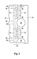
FIG. 3 shows a magnified illustration of the connection section of the knee from FIG. 2.
DETAILED DESCRIPTION
An ultrasonic surgical instrument in FIG. 1 comprises a handle 14 at its rear end, which the surgeon can grip when he uses the instrument. At the front end thereof, the instrument has a sleeve 15, through which a sonotrode 16 is guided, the end of which projects forward beyond the sleeve 15. The rear end of the sonotrode 16 is connected to an ultrasonic transducer 17. The ultrasonic transducer 17 receives an electric AC voltage signal with an ultrasonic frequency as input signal, which is generated by a signal generator not depicted in FIG. 1. The ultrasonic transducer comprises a piezoelectric element, by means of which the electric signal is converted into a mechanical vibration. The mechanical vibration is transferred to the sonotrode 16. Using the front end of the sonotrode 16, the vibration can be transferred to the tissue of a patient, in order to sever the latter.
A line 18 is guided to the front end of the instrument so as to be able to supply a rinsing fluid to the operating field. A second line 19 serves to suck liquids away from the operating field.
The instrument moreover comprises a knee 20, which forms a support structure of the instrument. The ultrasonic transducer 17 is suspended on the knee 20; the handle 14 is connected to the rear end of the knee 20 and the sleeve 15 is connected to the front end of the knee. The knee 20 is integral and can consist of e.g. stainless steel.
FIG. 2 shows the knee 20 in a magnified illustration.
The knee 20 comprises a retaining ring 21, on which the ultrasonic transducer 17 is suspended. The retaining ring 21 is provided with four bores 22, which form fastening elements for the ultrasonic transducer 17. The connection is established by means of screws, which are guided in through the bores 22. The retaining ring 21 is connected to a cladding section 24 by means of a connection section 23. On the circumference thereof, the cladding section 24 is provided with a thread 25, by means of which the handle 14 can be connected to the knee 20. The retaining ring 21 is positioned in such a way that the vibration transducer is suspended in the node of the vibration.
When the ultrasonic transducer 17 is in operation, the vibrations are transferred not only to the sonotrode 16 but also to the retaining ring 21, which is rigidly connected to the ultrasonic transducer 17. The connection section 23 serves to avoid a transfer of the vibrations from the retaining ring 21 to the cladding section 24. Otherwise, the whole instrument would be put into vibration by the cladding section 24.
In order to impart the effect of a spring element, which decouples the vibrations of the retaining ring 21 from the cladding section 24, to the connection section 23, the connection section 23 is provided with perforations 26, 27. In FIG. 3, in which the circumference of the knee 20 is projected into the plane, the perforations 26, 27 are depicted in a magnified manner. Accordingly, there is a perforation 26 for each of the four bores 22, which perforation is guided around the bore 22. The perforations 26 each have two end sections 28, which are aligned in the circumferential direction and positioned in the longitudinal direction in such a way that they intersect the bores 22 if they are continued. The perforations 26 are guided around the bores 22 by virtue of comprising a central section 29, which is displaced in parallel to the end sections 28 and is situated closer to the cladding section 24. The central sections 29 provide the option of moving the bores 22 closer to the cladding section 24, and so the knee 20 overall has a compact embodiment.
Further perforations 27, which are arranged parallel to one another and which enclose the end sections 28 therebetween, are formed in the region of the end sections 28. Thus, there is an overlap between the perforations 27 and each of the end sections 28.
There are connecting webs between the perforations 27 and the perforations 28, which webs extend in a labyrinthine manner between the retaining ring 21 and the cladding section 24. The connecting webs form an elastic connection between the retaining ring 21 and the cladding section 24 such that the vibrations transmitted to the retaining ring 21 are not transferred.
At the front end thereof, the knee 20 comprises a flange 30, which is angled with respect to the cladding section 24. The flange 30 comprises a thread (not visible in FIG. 2), into which the sleeve 15 can be screwed. A housing section 31, in the interior of which the ultrasonic transducer is held, extends between the flange 30 and the cladding section 24. The housing section 31 is provided with openings 32, 33, through which the lines 18, 19 can be guided.

Claims (19)

The invention claimed is:
1. An ultrasonic surgical instrument comprising an ultrasonic transducer (17) suspended on a support structure (20) and a sonotrode (16) connected to said ultrasonic transducer, the support structure (20) having a cladding section (24) extending around an interior, wherein the ultrasonic transducer (17) is suspended on a retaining ring (21), which is arranged in a continuation of the cladding section (24) and connected to the cladding section (24) via a longitudinally intermediate connection section (23) integrally connected to the retaining ring (21), the connection section defining a plurality of perforations (26, 27), which collectively angularly span the entire circumference of the connection section (23), wherein said support structure has the following order of arrangement in a proximal to distal direction relative to an operator: retaining ring, connecting section and cladding section.
2. The instrument of claim 1, wherein the circumferential length of each of the plurality of perforations (26, 27) is at least approximately twice the length of each of the plurality of perforations (26, 27) in the longitudinal direction.
3. The instrument of claim 1, comprising a first perforation (26) and a second perforation (27) spaced longitudinally from each other, wherein the first perforation (26) and second perforation (27) overlap in the circumferential direction.
4. The instrument of claim 3, wherein the first perforation (26) and second perforation (27) are longitudinally spaced a distance that is less than the longitudinal width of the perforations.
5. The instrument of claim 1, comprising a perforation (26) that is guided around a fastening element (22) for the ultrasonic transducer (17).
6. The instrument of claim 1, wherein two perforations (27) extend parallel to each other on opposite longitudinal sides of end sections (28) of two further perforations (26).
7. The instrument of claim 6, wherein the two perforations (27) and end sections (28) extend circumferentially substantially parallel to each other.
8. The instrument of claim 1, comprising a housing section (31) that encloses the interior and adjoins the cladding section.
9. The instrument of claim 8, wherein the housing section (31) includes one or more of an opening (32) for supplying a rinsing fluid to the interior and an opening (33) for removing fluid from the interior.
10. The instrument of claim 1, wherein the ultrasonic transducer (17) is positioned in the interior.
11. The instrument of claim 1, wherein the ultrasonic transducer (17) is suspended in a position longitudinally between two counter-vibrating structures in a position of reduced vibration.
12. The instrument of claim 1, wherein the cladding section (24) is provided with a connection element (25) for a handle (14).
13. An ultrasonic surgical instrument comprising an ultrasonic transducer (17) suspended on a support structure (20) and a sonotrode (16) connected to said ultrasonic transducer, the support structure (20) defining a central axis and having a cladding section (24) extending around an interior, wherein the ultrasonic transducer (17) is suspended on a retaining ring (21) longitudinally removed from the cladding section (24) with an intermediate connection section (23) transitioning the cladding section (24) to the retaining ring (21), the connection section (23) integrally connected to the retaining ring (21) and defining a plurality of longitudinally and circumferentially spaced perforations (26, 27) extending about the circumference and a handle fixedly (14) mounted to the cladding section.
14. The instrument of claim 13, wherein the cladding section (24), connection section (23) and retaining ring (21) are formed as a single unit.
15. The instrument of claim 13, wherein the plurality of longitudinally and circumferentially spaced perforations (26, 27) collectively angularly span the entire circumference of the support structure.
16. The instrument of claim 13, wherein the plurality of perforations (26, 27) are defined in the connection section (23) only.
17. The instrument of claim 13, wherein at least one of the perforations (26) comprises a pair of longitudinally spaced circumferentially extending segments (28, 29) connected via an intermediate segment.
18. The instrument of claim 17, wherein the intermediate segment extends substantially perpendicular to the pair of longitudinally extending segments (28, 29).
19. The instrument of claim 13, wherein a pair of the perforations (26, 27) extends circumferentially parallel to each other with at least a segment (28) of at least one additional perforation positioned longitudinally therebetween.
US14/358,343 2011-11-15 2012-11-14 Ultrasonic surgical instrument Expired - Fee Related US9549752B2 (en)

Applications Claiming Priority (4)

Application Number Priority Date Filing Date Title
DE102011086326 2011-11-15
DE102011086326A DE102011086326A1 (en) 2011-11-15 2011-11-15 Ultrasound surgical instrument
DE102011086326.5 2011-11-15
PCT/EP2012/072599 WO2013072357A2 (en) 2011-11-15 2012-11-14 Ultrasonic surgical instrument

Publications (2)

Publication Number Publication Date
US20150190167A1 US20150190167A1 (en) 2015-07-09
US9549752B2 true US9549752B2 (en) 2017-01-24

Family

ID=47222056

Family Applications (1)

Application Number Title Priority Date Filing Date
US14/358,343 Expired - Fee Related US9549752B2 (en) 2011-11-15 2012-11-14 Ultrasonic surgical instrument

Country Status (7)

Country Link
US (1) US9549752B2 (en)
EP (1) EP2779920A2 (en)
JP (1) JP5864772B2 (en)
CN (1) CN104023657B (en)
DE (1) DE102011086326A1 (en)
EA (1) EA025211B1 (en)
WO (1) WO2013072357A2 (en)

Cited By (3)

* Cited by examiner, † Cited by third party
Publication number Priority date Publication date Assignee Title
USD795420S1 (en) * 2011-02-11 2017-08-22 Lifecell Corporation Tissue transfer apparatus
USD857882S1 (en) * 2012-02-10 2019-08-27 Lifecell Corporation Tissue transfer apparatus
US10406297B2 (en) 2011-02-11 2019-09-10 Lifecell Corporation Devices and methods for tissue transfer

Families Citing this family (7)

* Cited by examiner, † Cited by third party
Publication number Priority date Publication date Assignee Title
WO2016080303A1 (en) * 2014-11-21 2016-05-26 オリンパス株式会社 Surgical treatment instrument
JP6147440B1 (en) * 2015-07-23 2017-06-14 オリンパス株式会社 Ultrasonic treatment device and ultrasonic treatment assembly
CN105266954B (en) * 2015-11-24 2017-09-26 湖南大学 A kind of ultrasonic scalpel
US10492885B2 (en) * 2015-12-17 2019-12-03 Ethicon Llc Ultrasonic surgical instrument with cleaning port
US10231749B2 (en) * 2015-12-21 2019-03-19 Ethicon Llc Ultrasonic surgical instrument with blade replacement features
US10702296B2 (en) * 2016-05-25 2020-07-07 Ethicon Llc Ultrasonic surgical instrument with cooling conduit
CN110151258A (en) * 2019-05-01 2019-08-23 杭州康基医疗器械股份有限公司 The support system of ultrasound waveguide

Citations (21)

* Cited by examiner, † Cited by third party
Publication number Priority date Publication date Assignee Title
US3671887A (en) 1968-02-16 1972-06-20 Philips Corp Delay line
US4315181A (en) 1980-04-22 1982-02-09 Branson Ultrasonics Corporation Ultrasonic resonator (horn) with skewed slots
US4681561A (en) 1986-01-24 1987-07-21 Coopervision, Inc. Ultrasonic decoupling sleeve
JPS62298346A (en) 1986-06-18 1987-12-25 オリンパス光学工業株式会社 Ultrasonic lithotomic apparatus
JPH03146047A (en) 1989-11-01 1991-06-21 Olympus Optical Co Ltd Ultrasonic medical treatment device
US5057119A (en) 1989-12-12 1991-10-15 Ultracision Inc. Apparatus and methods for attaching and detaching an ultrasonic actuated blade/coupler and an acoustical mount therefor
JPH0531118A (en) 1991-07-26 1993-02-09 Olympus Optical Co Ltd Ultrasonic therapeutic apparatus
JPH06133981A (en) 1992-10-28 1994-05-17 Sumitomo Bakelite Co Ltd Protective cover for ultrasonic scalpel
US5526815A (en) 1993-01-29 1996-06-18 Siemens Aktiengesellschat Therapy apparatus for locating and treating a zone located in the body of a life form with acoustic waves
US5626560A (en) 1993-04-13 1997-05-06 Soring Medizintechnik Gmbh Diathermic hand-held instrument with an endoscopic probe
JPH10127653A (en) 1996-10-31 1998-05-19 Olympus Optical Co Ltd Ultrasonic treatment equipment
US5921999A (en) 1997-06-03 1999-07-13 Dileo; Frank System and method employing a pie-zoelectric crystal and transverse oscillation to perform a capsulotomy
JP2001079012A (en) 1999-09-13 2001-03-27 Olympus Optical Co Ltd Ultrasonic trocar device
US6551337B1 (en) 1999-10-05 2003-04-22 Omnisonics Medical Technologies, Inc. Ultrasonic medical device operating in a transverse mode
US20040037626A1 (en) * 2002-08-26 2004-02-26 Shorya Awtar Mechanisms having motion with constrained degrees of freedom
WO2004021404A2 (en) 2002-08-29 2004-03-11 Volcano Therapeutics, Inc. Ultrasonic imaging devices and methods of fabrication
US20050020966A1 (en) 2002-07-22 2005-01-27 Holger Soring Medical treatment apparatus
US20090030437A1 (en) * 2007-07-27 2009-01-29 Houser Kevin L Surgical instruments
US20110196405A1 (en) * 2010-02-11 2011-08-11 Ethicon Endo-Surgery, Inc. Ultrasonic surgical instrument with comb-like tissue trimming device
US20120049422A1 (en) * 2010-08-31 2012-03-01 General Electric Company Slotted spring vibration isolator
US20120204550A1 (en) * 2009-10-05 2012-08-16 Farid Al-Bender Active 3d.o.f. stiffness element

Family Cites Families (6)

* Cited by examiner, † Cited by third party
Publication number Priority date Publication date Assignee Title
US5417672A (en) * 1993-10-04 1995-05-23 Baxter International Inc. Connector for coupling an ultrasound transducer to an ultrasound catheter
US6086369A (en) * 1997-01-13 2000-07-11 Parkell Products, Inc. Ultrasonic dental scaler insert
WO2001053032A1 (en) * 2000-01-21 2001-07-26 Hesse & Knipps Gmbh Holding device for an ultrasonic transducer
JP2003190180A (en) * 2001-12-27 2003-07-08 Miwatec:Kk Compound vibration ultrasonic hand piece
CN1871873A (en) * 2003-08-21 2006-11-29 美国技术公司 Parametric tranducer having an emitter film
CN201320217Y (en) * 2008-10-07 2009-10-07 王华林 Ultrasound surgical forceps

Patent Citations (23)

* Cited by examiner, † Cited by third party
Publication number Priority date Publication date Assignee Title
US3671887A (en) 1968-02-16 1972-06-20 Philips Corp Delay line
US4315181A (en) 1980-04-22 1982-02-09 Branson Ultrasonics Corporation Ultrasonic resonator (horn) with skewed slots
US4681561A (en) 1986-01-24 1987-07-21 Coopervision, Inc. Ultrasonic decoupling sleeve
US4816017A (en) 1986-01-24 1989-03-28 Coopervision, Inc. Ultrasonic decoupling sleeve
JPS62298346A (en) 1986-06-18 1987-12-25 オリンパス光学工業株式会社 Ultrasonic lithotomic apparatus
JPH03146047A (en) 1989-11-01 1991-06-21 Olympus Optical Co Ltd Ultrasonic medical treatment device
US5057119A (en) 1989-12-12 1991-10-15 Ultracision Inc. Apparatus and methods for attaching and detaching an ultrasonic actuated blade/coupler and an acoustical mount therefor
JPH0531118A (en) 1991-07-26 1993-02-09 Olympus Optical Co Ltd Ultrasonic therapeutic apparatus
JPH06133981A (en) 1992-10-28 1994-05-17 Sumitomo Bakelite Co Ltd Protective cover for ultrasonic scalpel
US5526815A (en) 1993-01-29 1996-06-18 Siemens Aktiengesellschat Therapy apparatus for locating and treating a zone located in the body of a life form with acoustic waves
US5626560A (en) 1993-04-13 1997-05-06 Soring Medizintechnik Gmbh Diathermic hand-held instrument with an endoscopic probe
JPH10127653A (en) 1996-10-31 1998-05-19 Olympus Optical Co Ltd Ultrasonic treatment equipment
US5921999A (en) 1997-06-03 1999-07-13 Dileo; Frank System and method employing a pie-zoelectric crystal and transverse oscillation to perform a capsulotomy
JP2001079012A (en) 1999-09-13 2001-03-27 Olympus Optical Co Ltd Ultrasonic trocar device
US6551337B1 (en) 1999-10-05 2003-04-22 Omnisonics Medical Technologies, Inc. Ultrasonic medical device operating in a transverse mode
US20030125645A1 (en) 1999-10-05 2003-07-03 Omnisonics Medical Technologies, Inc. Ultrasonic medical device operating in a transverse mode
US20050020966A1 (en) 2002-07-22 2005-01-27 Holger Soring Medical treatment apparatus
US20040037626A1 (en) * 2002-08-26 2004-02-26 Shorya Awtar Mechanisms having motion with constrained degrees of freedom
WO2004021404A2 (en) 2002-08-29 2004-03-11 Volcano Therapeutics, Inc. Ultrasonic imaging devices and methods of fabrication
US20090030437A1 (en) * 2007-07-27 2009-01-29 Houser Kevin L Surgical instruments
US20120204550A1 (en) * 2009-10-05 2012-08-16 Farid Al-Bender Active 3d.o.f. stiffness element
US20110196405A1 (en) * 2010-02-11 2011-08-11 Ethicon Endo-Surgery, Inc. Ultrasonic surgical instrument with comb-like tissue trimming device
US20120049422A1 (en) * 2010-08-31 2012-03-01 General Electric Company Slotted spring vibration isolator

Non-Patent Citations (2)

* Cited by examiner, † Cited by third party
Title
International Preliminary Report on Patentability dated May 20, 2014 (PCT/EP2012/072599).
International Search Report dated Sep. 30, 2013 (PCT/EP2012/072599).

Cited By (3)

* Cited by examiner, † Cited by third party
Publication number Priority date Publication date Assignee Title
USD795420S1 (en) * 2011-02-11 2017-08-22 Lifecell Corporation Tissue transfer apparatus
US10406297B2 (en) 2011-02-11 2019-09-10 Lifecell Corporation Devices and methods for tissue transfer
USD857882S1 (en) * 2012-02-10 2019-08-27 Lifecell Corporation Tissue transfer apparatus

Also Published As

Publication number Publication date
DE102011086326A1 (en) 2013-05-16
CN104023657B (en) 2017-04-05
JP2015500683A (en) 2015-01-08
US20150190167A1 (en) 2015-07-09
EA201490900A1 (en) 2016-01-29
CN104023657A (en) 2014-09-03
EP2779920A2 (en) 2014-09-24
EA025211B1 (en) 2016-11-30
WO2013072357A2 (en) 2013-05-23
WO2013072357A3 (en) 2013-11-28
JP5864772B2 (en) 2016-02-17

Similar Documents

Publication Publication Date Title
US9549752B2 (en) Ultrasonic surgical instrument
US9358407B2 (en) Ultrasonic actuated unit and ultrasonic treatment device
AU725313B2 (en) Damping ultrasonic transmission components
ES2547487T3 (en) Ultrasonic surgical instrument blades
US20030114873A1 (en) Ultrasonic instrument with coupler for work tip
EP3243465B1 (en) Ultrasonic probe and ultrasonic instrument
US9345505B2 (en) Ultrasonic transmitting unit
US9764165B2 (en) Ultrasonic transmitting unit
US9186526B2 (en) Ultrasonic treatment probe
US11583307B2 (en) Ultrasonic transmitter unit
US20170209168A1 (en) Ultrasonic probe
US11369513B2 (en) Low-cost disposable ultrasonic surgical handpiece
EP3000424B1 (en) Ultrasonic treatment device
EP3167832B1 (en) Ultrasonic probe and ultrasonic treatment device
JP6033503B1 (en) Ultrasonic treatment device and ultrasonic treatment assembly
US20220265308A1 (en) Treatment device with damping feature
JPH0515545A (en) Ultrasonic treating apparatus

Legal Events

Date Code Title Description
AS Assignment

Owner name: SORING GMBH, GERMANY

Free format text: ASSIGNMENT OF ASSIGNORS INTEREST;ASSIGNORS:MEIER, MARKUS;NEUMANN, FLORIAN;HAGEDORN, HENDRIK;SIGNING DATES FROM 20140716 TO 20140826;REEL/FRAME:034104/0246

STCF Information on status: patent grant

Free format text: PATENTED CASE

FEPP Fee payment procedure

Free format text: MAINTENANCE FEE REMINDER MAILED (ORIGINAL EVENT CODE: REM.); ENTITY STATUS OF PATENT OWNER: SMALL ENTITY

LAPS Lapse for failure to pay maintenance fees

Free format text: PATENT EXPIRED FOR FAILURE TO PAY MAINTENANCE FEES (ORIGINAL EVENT CODE: EXP.); ENTITY STATUS OF PATENT OWNER: SMALL ENTITY

STCH Information on status: patent discontinuation

Free format text: PATENT EXPIRED DUE TO NONPAYMENT OF MAINTENANCE FEES UNDER 37 CFR 1.362

FP Lapsed due to failure to pay maintenance fee

Effective date: 20210124