US9556733B2 - Tunnel boring machine disc cutters and related methods of manufacture - Google Patents
Tunnel boring machine disc cutters and related methods of manufacture Download PDFInfo
- Publication number
- US9556733B2 US9556733B2 US13/790,046 US201313790046A US9556733B2 US 9556733 B2 US9556733 B2 US 9556733B2 US 201313790046 A US201313790046 A US 201313790046A US 9556733 B2 US9556733 B2 US 9556733B2
- Authority
- US
- United States
- Prior art keywords
- cutter
- superhard
- elements
- bearing
- central axis
- Prior art date
- Legal status (The legal status is an assumption and is not a legal conclusion. Google has not performed a legal analysis and makes no representation as to the accuracy of the status listed.)
- Active, expires
Links
Images


Classifications
-
- E—FIXED CONSTRUCTIONS
- E21—EARTH DRILLING; MINING
- E21D—SHAFTS; TUNNELS; GALLERIES; LARGE UNDERGROUND CHAMBERS
- E21D9/00—Tunnels or galleries, with or without linings; Methods or apparatus for making thereof; Layout of tunnels or galleries
- E21D9/10—Making by using boring or cutting machines
- E21D9/1006—Making by using boring or cutting machines with rotary cutting tools
-
- E—FIXED CONSTRUCTIONS
- E21—EARTH DRILLING; MINING
- E21B—EARTH DRILLING, e.g. DEEP DRILLING; OBTAINING OIL, GAS, WATER, SOLUBLE OR MELTABLE MATERIALS OR A SLURRY OF MINERALS FROM WELLS
- E21B10/00—Drill bits
- E21B10/08—Roller bits
- E21B10/12—Roller bits with discs cutters
-
- E—FIXED CONSTRUCTIONS
- E21—EARTH DRILLING; MINING
- E21B—EARTH DRILLING, e.g. DEEP DRILLING; OBTAINING OIL, GAS, WATER, SOLUBLE OR MELTABLE MATERIALS OR A SLURRY OF MINERALS FROM WELLS
- E21B10/00—Drill bits
- E21B10/08—Roller bits
- E21B10/22—Roller bits characterised by bearing, lubrication or sealing details
-
- E—FIXED CONSTRUCTIONS
- E21—EARTH DRILLING; MINING
- E21C—MINING OR QUARRYING
- E21C25/00—Cutting machines, i.e. for making slits approximately parallel or perpendicular to the seam
- E21C25/16—Machines slitting solely by one or more rotating saws, cutting discs, or wheels
- E21C25/18—Saws; Discs; Wheels
-
- E—FIXED CONSTRUCTIONS
- E21—EARTH DRILLING; MINING
- E21D—SHAFTS; TUNNELS; GALLERIES; LARGE UNDERGROUND CHAMBERS
- E21D9/00—Tunnels or galleries, with or without linings; Methods or apparatus for making thereof; Layout of tunnels or galleries
- E21D9/10—Making by using boring or cutting machines
- E21D9/1006—Making by using boring or cutting machines with rotary cutting tools
- E21D9/104—Cutting tool fixtures
-
- F—MECHANICAL ENGINEERING; LIGHTING; HEATING; WEAPONS; BLASTING
- F16—ENGINEERING ELEMENTS AND UNITS; GENERAL MEASURES FOR PRODUCING AND MAINTAINING EFFECTIVE FUNCTIONING OF MACHINES OR INSTALLATIONS; THERMAL INSULATION IN GENERAL
- F16C—SHAFTS; FLEXIBLE SHAFTS; ELEMENTS OR CRANKSHAFT MECHANISMS; ROTARY BODIES OTHER THAN GEARING ELEMENTS; BEARINGS
- F16C17/00—Sliding-contact bearings for exclusively rotary movement
- F16C17/10—Sliding-contact bearings for exclusively rotary movement for both radial and axial load
-
- F—MECHANICAL ENGINEERING; LIGHTING; HEATING; WEAPONS; BLASTING
- F16—ENGINEERING ELEMENTS AND UNITS; GENERAL MEASURES FOR PRODUCING AND MAINTAINING EFFECTIVE FUNCTIONING OF MACHINES OR INSTALLATIONS; THERMAL INSULATION IN GENERAL
- F16C—SHAFTS; FLEXIBLE SHAFTS; ELEMENTS OR CRANKSHAFT MECHANISMS; ROTARY BODIES OTHER THAN GEARING ELEMENTS; BEARINGS
- F16C33/00—Parts of bearings; Special methods for making bearings or parts thereof
- F16C33/02—Parts of sliding-contact bearings
- F16C33/04—Brasses; Bushes; Linings
- F16C33/043—Sliding surface consisting mainly of ceramics, cermets or hard carbon, e.g. diamond like carbon [DLC]
-
- F—MECHANICAL ENGINEERING; LIGHTING; HEATING; WEAPONS; BLASTING
- F16—ENGINEERING ELEMENTS AND UNITS; GENERAL MEASURES FOR PRODUCING AND MAINTAINING EFFECTIVE FUNCTIONING OF MACHINES OR INSTALLATIONS; THERMAL INSULATION IN GENERAL
- F16C—SHAFTS; FLEXIBLE SHAFTS; ELEMENTS OR CRANKSHAFT MECHANISMS; ROTARY BODIES OTHER THAN GEARING ELEMENTS; BEARINGS
- F16C33/00—Parts of bearings; Special methods for making bearings or parts thereof
- F16C33/02—Parts of sliding-contact bearings
- F16C33/04—Brasses; Bushes; Linings
- F16C33/26—Brasses; Bushes; Linings made from wire coils; made from a number of discs, rings, rods, or other members
-
- F—MECHANICAL ENGINEERING; LIGHTING; HEATING; WEAPONS; BLASTING
- F16—ENGINEERING ELEMENTS AND UNITS; GENERAL MEASURES FOR PRODUCING AND MAINTAINING EFFECTIVE FUNCTIONING OF MACHINES OR INSTALLATIONS; THERMAL INSULATION IN GENERAL
- F16C—SHAFTS; FLEXIBLE SHAFTS; ELEMENTS OR CRANKSHAFT MECHANISMS; ROTARY BODIES OTHER THAN GEARING ELEMENTS; BEARINGS
- F16C2352/00—Apparatus for drilling
-
- Y—GENERAL TAGGING OF NEW TECHNOLOGICAL DEVELOPMENTS; GENERAL TAGGING OF CROSS-SECTIONAL TECHNOLOGIES SPANNING OVER SEVERAL SECTIONS OF THE IPC; TECHNICAL SUBJECTS COVERED BY FORMER USPC CROSS-REFERENCE ART COLLECTIONS [XRACs] AND DIGESTS
- Y10—TECHNICAL SUBJECTS COVERED BY FORMER USPC
- Y10T—TECHNICAL SUBJECTS COVERED BY FORMER US CLASSIFICATION
- Y10T29/00—Metal working
- Y10T29/49—Method of mechanical manufacture
- Y10T29/49826—Assembling or joining
Definitions
- cutters or bits are presently used in mechanical excavation systems.
- One type of cutter commonly used on cutter heads in rock excavation is a disc-type rolling cutter.
- hardened steel disc cutters are frequently used on cutterheads employed in tunnel boring, raise drilling, large diameter blind drilling, and/or small diameter drilling systems.
- the disc cutter may be used to apply great thrust on the cutter, and consequently pressure on the rock to be cut, a zone of rock directly beneath (i.e., in the cutting direction) and adjacent to the disc cutter is crushed, normally forming very fine particles.
- the crushed zone may form a hydraulic-like pressure downward (again, in the cutting direction) and outward against the adjacent rock.
- the adjacent rock then cracks, and chips spall from the rock face being excavated.
- the crushed rock is then collected and removed as debris.
- disc cutters can be a significant limitation in the operating efficiency of mechanical excavation systems using such cutters.
- the disc cutters are typically pushed against hard rock surfaces (i.e., tunnel faces) with very significant forces including high shock loads and work in an abrasive, high wear environment, the disc cutters can wear at a rapid rate.
- disc cutters typically include bearing systems that allow the disc cutters to rotate on the target surface as the cutterheads rotate. If this bearing system fails, the disc cutter can stop turning. When the disc cutter stops turning, the portion of the disc cutter in contact with the target surface slides. This sliding contact can wear the disc cutter rapidly into a flat, wide spot that no longer is able to apply adequate compressive force against the target surface to crush hard rock or other hardened material.
- disc cutters may be replaced.
- mechanical excavation systems can be stopped for several hours while the disc cutters are removed, replaced, and/or repaired. This time and effort intensive repair activity reduces the overall efficiency or rate of mechanical excavation systems using the disc cutters.
- Various embodiments of the invention relate to disc cutters and related methods of manufacture.
- the various embodiments of the disc cutters may be used in tunnel boring machines, raise drilling systems, large diameter blind drilling systems, and other types of mechanical systems.
- a disc cutter for use on a tunnel boring machine may include a shaft and a cutter assembly rotatably mounted on the shaft.
- the cutter assembly may include a cutter ring extending circumferentially about a central axis and one or more bearing apparatuses rotatably mounting the cutter assembly to the shaft.
- Each bearing apparatuses may include a rotor extending circumferentially about the central axis and a first plurality of superhard bearing elements distributed circumferentially about the central axis.
- Each first superhard bearing element may be attached to the rotor and may include a bearing surface.
- the bearing apparatuses may further include a stator extending circumferentially about the central axis and a second plurality of superhard bearing elements attached to the stator that are generally opposed to the first plurality of superhard bearing elements of the rotor.
- a disc cutter may include a shaft and a cutter assembly rotatably mounted on the shaft.
- the cutter assembly may include a cutter ring extending circumferentially about a central axis that includes a radially inner surface and a radially outer surface.
- the disc cutter may also include one or more roller bearing apparatuses mounting the cutter assembly to the shaft.
- Each bearing apparatus may include a rotor extending circumferentially about the central axis and a first plurality of superhard raceway elements distributed about the central axis.
- Each of the first plurality of superhard raceway elements may be attached to the rotor and may include a raceway surface positioned and configured to form a first portion of a raceway.
- the one or more bearing apparatuses may also include a stator extending circumferentially about the central axis and a second plurality of superhard raceway elements attached the stator.
- Each of the second plurality of superhard raceway elements may include a raceway surface positioned and configured to form a second portion of the raceway.
- the one or more roller bearing apparatuses may further include a plurality of rolling elements interposed between the rotor and the stator.
- a disc cutter for use on a tunnel boring machine may include a shaft and a cutter assembly rotatably mounted on the shaft.
- the cutter assembly may include a cutter ring having an inner surface and an outer surface including a plurality of pockets formed therein.
- the disc cutter may further include a plurality of superhard cutter elements distributed circumferentially about an axis. Each of the plurality of superhard cutting elements may be positioned in a corresponding one of the pockets and comprises polycrystalline diamond (“PCD”). At least a number of the superhard cutting elements may extend beyond the outer surface of the cutter ring.
- the disc cutter may further include one or more bearing apparatuses rotatably mounting the cutter assembly to the shaft.
- the one or more bearing apparatuses may include a rotor including a first plurality of superhard bearing elements distributed circumferentially about an axis. Each of the first plurality of superhard bearing elements may include a bearing surface.
- the one or more bearing apparatuses may further include a stator having a second plurality of superhard bearing elements generally opposed to the first plurality of superhard bearing elements of the rotor.
- a method of manufacturing a disc cutter for use on a tunnel boring machine may include providing a cutter assembly comprising a cutter ring having a cutting surface. The method further includes rotatably mounting the cutter assembly on a shaft via one or more bearing apparatuses.
- Each bearing apparatus may include a rotor extending circumferentially about the central axis and a first plurality of superhard bearing elements distributed circumferentially about the central axis.
- Each of the first plurality of superhard bearing elements may be attached to the rotor and may include a bearing surface.
- Each bearing apparatus may further include a stator extending circumferentially about the central axis and a second plurality of superhard bearing elements attached to the stator. The second plurality of superhard bearing elements may be generally opposed the first plurality of superhard bearing elements of the rotor.
- FIG. 1 is a schematic perspective view of a tunnel boring machine that may utilize any of the disclosed disc cutters according to various embodiments;
- FIG. 2 is an isometric view of a disc cutter according to an embodiment
- FIG. 3 is a cross-sectional view taken along line 3 - 3 of the disc cutter shown in FIG. 2 ;
- FIG. 4A is a partial, cross-sectional view of the cutter assembly shown in FIG. 3 having the cutting element removed according to another embodiment
- FIG. 4B is a partial, cross-sectional view of the cutter assembly shown in FIG. 4A having the cutting element attached;
- FIG. 5 is a partial, cross-sectional view of a disc cutter shown in FIG. 2 according to another embodiment
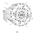
- FIG. 6 is an exploded isometric view of a bearing apparatus removed from the disc cutter shown in FIG. 2 ;
- FIG. 7 is a partial, cross-sectional view of a disc cutter according to another embodiment
- FIG. 8 is a partial, cross-sectional view of a disc cutter according to another embodiment
- FIG. 9 is an exploded isometric view of a bearing apparatus removed from the disc cutter shown in FIG. 8 ;
- FIG. 10 is a partial, cross-sectional view of a disc cutter according to another embodiment.
- FIG. 11 is a partial, cross-sectional view of a disc cutter according to another embodiment.
- Embodiments of the invention generally relate to tunnel boring machine disc cutters, and related methods of manufacture.
- the various embodiments of the cutter assemblies and the disc cutters may be used in tunnel boring machines (“TBMs”), raise drilling systems, large diameter blind drilling systems, and other types of systems.
- TBMs tunnel boring machines
- FIG. 1 is a schematic perspective view of a TBM 10 according to an embodiment.
- the TBM 10 may include a large rotating cutterhead or head 11 positioned at a front end of the TBM 10 .
- the head 11 may be configured to rotate around a rotation axis 12 that is generally coaxial with the geometry of the tunnel.
- one or more disc cutters 13 may be mounted to the rotating head 11 .
- the disc cutters 13 may be mounted onto the head 11 in one or more patterns so that as the head 11 rotates about the rotation axis 12 , the disc cutters 13 are able to contact selected portions of a target surface or tunnel face.
- the disc cutters 13 may comprise one or more cutter assemblies rotatably mounted via bearings onto a shaft.
- the shaft is secured to the head 11 and defines another rotation axis for the disc cutter 13 that is generally orthogonal to the rotation axis 12 of head 11 .
- the cutter assembly of the disc cutter 13 rotates on the shaft.
- the disc cutters 13 may be configured to perform the task of excavating material (e.g., rock) from the target surface or tunnel face. For example, as the head 11 advances and rotates, the disc cutters 13 rotate and are pushed against the tunnel face, typically under power from a system of hydraulic cylinders (not shown). The disc cutters 13 fractionate, crush, loosen materials, or combinations thereof, on the tunnel face, which may be transported away by the TBM 10 . As described in more detailed below, in an embodiment, the disc cutters 13 may include a cutting surface configured and positioned to contact and cut the target surface or tunnel face. As the loosened material is removed, the tunnel length increases as the TBM 10 advances to maintain engagement of the head with the tunnel face. Hydraulic cylinders may also be deployed along with means which push against the sides of the tunnel in order to counter the force of the disc cutters 13 against the tunnel face.
- Hydraulic cylinders may also be deployed along with means which push against the sides of the tunnel in order to counter the force of the disc cutters 13 against the tunnel
- FIGS. 2 and 3 are isometric and cross-sectional views of a disc cutter 213 according to an embodiment.
- the disc cutter 213 may include a shaft 202 configured to be fixedly attached to the head 11 .
- the disc cutter 213 may further include a cutter assembly 204 including a cutter ring 206 extending circumferentially about a central axis 230 .
- the cutter ring 206 may be attached to a hub 208 with a retainer member 210 .
- the cutter assembly 204 may be rotatably mounted to the shaft 202 with one or more bearing apparatuses.
- the cutter assembly 204 may be rotatably mounted to the shaft 202 with a pair of bearing apparatuses 212 A, 212 B.
- each of the bearing apparatuses 212 A, 212 B may include an inner race or stator 224 and an outer race or rotor 226 .
- the inner races 224 may be fixed attached to the shaft 202 via an inner member 217 .
- the inner member 217 may include a pair of end retainer covers 218 , 220 positioned on either side of the hub 208 .
- the cutter assembly 204 may be rotatable about the shaft 202 , and the end retainer covers 218 , 220 may be fixed to the shaft 202 .
- a rotary seal group 222 may be positioned at the interface between each of the end retainer cover 218 , 220 and the cutter assembly 204 .
- the rotary seal group 222 may be configured to provide a seal to help prevent the entry of dirt, rock, water, or other contaminants that could damage or destroy the bearing apparatuses 212 A, 212 B.
- the cutter ring 206 of the cutter assembly 204 may extend circumferentially about the central axis 230 and may include a radially outer surface 206 A and a radially inner surface 206 B defining an opening through which the shaft 202 may extend.
- the cutter ring 206 may be made from a variety of different materials.
- the cutter ring 206 may comprise a metal, alloy steel, a metal alloy, carbon steel, stainless steel, tungsten carbide, or any other suitable metal or conductive or non-conductive material.
- the cutter ring 206 may comprise an annular ring exhibiting a wedge-like cross-sectional geometric shape.
- the cutter ring 206 may include a base portion 256 from which a pair of side portions 258 extend and converge to define a crest 260 . While the cutter ring 206 is illustrated exhibiting a generally wedge-like cross-sectional shape, the cutter ring 206 may exhibit any suitable cross-sectional geometric shape. For example, the cutter ring 206 may exhibit a constant cross-sectional shape, a generally conical cross-sectional shape, a generally rectangular cross-sectional shape, a bell-like cross-sectional shape, an asymmetric cross-sectional shape, a generally triangular cross-sectional shape, a generally trapezoidal cross-sectional shape, combinations thereof, or any other suitable cross-sectional geometric shape.
- the cutter ring 206 may include a plurality of pockets 262 formed in the crest 260 .
- the pockets 262 may be arranged in a single row about a rotation axis 230 .
- the pockets 262 may be arranged in two rows, three rows, four rows, or any other suitable number of rows about the rotation axis 230 .
- the cutter assembly 204 may include a plurality of cutting elements 264 attached to the cutter ring 206 . Each of the cutting elements 264 may be distributed circumferentially about the central axis 230 . In an embodiment, gaps 266 may be located between adjacent cutting elements 264 . In an embodiment, at least one of, some of, or all of the gaps 266 may exhibit a width of about 0.00020 inches to 0.5 inches, such as about 0.00040 inches to 0.0010 inches, about 0.00040 inches to 0.080 inches, or 0.1 inches to 0.2 inches, 0.3 inches to 0.4 inches, or about 0.4 inches to 0.5 inches. In other embodiments, the gaps 266 may substantially be zero.
- one or more of the cutting elements 264 may have a generally domed hemispherical-like shape. In other embodiments, one or more of the cutting elements 264 may exhibit a generally rounded rectangular shape, a hemispherical shape, a pointed shape, a generally oval shape, a generally angular shape, combinations thereof, or any other suitable shape.
- Each cutting element 264 may include a superhard body 268 having a working upper surface 268 A and an opposing back surface 268 B.
- the superhard body 268 may comprise a superhard layer 268 D (e.g. a PCD layer) bonded or otherwise attached to a substrate 268 E (e.g., tungsten carbide).
- Each cutting element 264 may optionally include multiple layers or other components. For instance, the back surface 268 B of one or more of the cutting elements 264 may be bonded or otherwise attached to a backing portion.
- superhard means a material having a hardness at least equal to a hardness of tungsten carbide.
- the superhard bodies e.g., superhard body 268
- the superhard bodies may at least partially comprise one or more superhard materials, such as natural diamond, sintered PCD, polycrystalline cubic boron nitride, diamond grains bonded together with silicon carbide, or combinations of the foregoing.
- cutting elements having a PCD body may be formed and bonded to a backing portion using an ultra-high pressure, ultra-high temperature (“HPHT”) sintering process.
- HPHT ultra-high pressure, ultra-high temperature
- Such cutting elements having a PCD body may be fabricated by placing a cemented carbide backing portion, such as a cobalt-cemented tungsten carbide substrate, into a container or cartridge with a volume of diamond particles positioned on a surface of the cemented carbide substrate.
- a cemented carbide backing portion such as a cobalt-cemented tungsten carbide substrate
- a number of such cartridges may be loaded into an HPHT press.
- the backing portions and diamond particles may then be processed under HPHT conditions in the presence of a catalyst material that causes the diamond particles to bond to one another to form a diamond table having a matrix of bonded diamond crystals.
- the catalyst material is often a metal-solvent catalyst, such as cobalt, nickel, or iron, which facilitates intergrowth and bonding of the diamond particles.
- a constituent of the cemented carbide backing portion such as cobalt from a cobalt-cemented tungsten carbide substrate, liquefies and sweeps from a region adjacent to the volume of diamond particles into interstitial regions between the diamond particles during the HPHT process.
- the cobalt may act as a catalyst to facilitate the formation of bonded diamond gains.
- the polycrystalline diamond body may be leached to at least partially or substantially completely remove the metal-solvent catalyst (e.g., cobalt, iron, nickel, or alloys thereof) that was used to initially sinter precursor diamond particles that form the polycrystalline diamond.
- the metal-solvent catalyst e.g., cobalt, iron, nickel, or alloys thereof
- an infiltrant used to re-infiltrate a preformed leached polycrystalline diamond table may be leached or otherwise removed to a selected depth from the upper working surface.
- the polycrystalline diamond may be unleached and include a metal-solvent catalyst (e.g., cobalt, iron, nickel, or alloys thereof) that was used to initially sinter the precursor diamond particles that form the polycrystalline diamond or an infiltrant used to re-infiltrate a preformed leached polycrystalline diamond body.
- a metal-solvent catalyst e.g., cobalt, iron, nickel, or alloys thereof
- cobalt, iron, nickel, or alloys thereof e.g., cobalt, iron, nickel, or alloys thereof
- the diamond particles that may form the PCD in the superhard body may also exhibit a larger size and at least one relatively smaller size.
- the phrases “relatively larger” and “relatively smaller” refer to particle sizes (by any suitable method) that differ by at least a factor of two (e.g., 30 ⁇ m and 15 ⁇ m).
- the diamond particles may include a portion exhibiting a relatively larger size (e.g., 40 ⁇ m, 30 ⁇ m, 20 ⁇ m, 15 ⁇ m, 12 ⁇ m, 10 ⁇ m, 8 ⁇ m) and another portion exhibiting at least one relatively smaller size (e.g., 6 ⁇ m, 5 ⁇ m, 4 ⁇ m, 3 ⁇ m, 2 ⁇ m, 1 ⁇ m, 0.5 ⁇ m, less than 0.5 ⁇ m, 0.1 ⁇ m, less than 0.1 ⁇ m).
- the diamond particles may include a portion exhibiting a relatively larger size between about 10 ⁇ m and about 40 ⁇ m and another portion exhibiting a relatively smaller size between about 1 ⁇ m and about 4 ⁇ m.
- the diamond particles may comprise three or more different sizes (e.g., one relatively larger size and two or more relatively smaller sizes), without limitation.
- the PCD may, in some cases, exhibit an average grain size that is the same or similar to any of the diamond particles sizes and distributions discussed above.
- the cutting elements 264 may be free-standing (e.g., substrateless) and formed from a PCD body that is at least partially or fully leached to remove a metal-solvent catalyst initially used to sinter the polycrystalline diamond body.
- the leached PCD body may be formed to exhibit a porosity of about 1%-10% by volume.
- the leached pores of the PCD body may be impregnated with lubricant to assist in minimizing friction caused by contact of rock materials on the cutter assembly 204 .
- the PCD body may exhibit a selected porosity that is higher or lower.
- a cutting surface is a substantially continuous or discontinuous surface or surfaces that are configured to contact and cut a target surface or a tunnel face.
- the cutting elements 264 may be sized and configured to form a superhard cutting surface or cutting edge.
- the cutting elements 264 may be positioned such that at least a portion of the working upper surface 268 A of each cutting element 264 projects beyond the crest 260 of the cutter ring 206 .
- the superhard body 268 may exhibit a modulus of elasticity between about 800 GPa and about 1200 GPa (e.g., about 800 GPa to about 850 GPa). In other embodiments, the superhard body 268 may exhibit a modulus of elasticity greater than about 800 GPa. In other embodiments, the superhard body 268 may exhibit a selected modulus of elasticity that is higher or lower.
- the cutting elements 264 may enhance the general load capacity of the cutter assembly 204 . Further, the cutting elements 264 may form a cutting surface that is more abrasive and resistant to corrosion than a traditional cutting surface (i.e., steel). Optionally, a relatively high thermal conductivity of the cutting elements 264 may also help reduce adhesive wear and resulting scuffing of the cutter ring 206 .
- the superhard cutting surface may exhibit a thermal conductivity of about 543 W/m-K, which is about twelve (12) times the thermal conductivity of steel.
- the superhard cutting surface may exhibit a thermal conductivity of at least about 300 W/m-K; at least about 800 W/m-K; at least about 1300 W/m-K; or at least about 2000 W/m-K.
- the superhard cutting surface may exhibit a thermal conductivity of about 300 W/m-K to about 2000 W/m-K; about 700 W/m-K to about 1600 W/m-K; or about 1000 W/m-K to about 1300 W/m-K.
- the thermal conductivity of the superhard cutting surface may be larger or smaller. Accordingly, heat generated by eventual skidding and/or slipping of the cutting elements 264 on rock materials may be quickly conducted away from the cutter ring 206 .
- the superhard cutting surfaces may exhibit thermal conductivities that are higher or lower.
- the cutting elements 264 may be omitted.
- the cutter ring 206 may not include cutting elements and the cutting surface of the cutter ring 206 may be formed by the crest 260 of the cutter ring 206 .
- the cutting elements 264 may be mounted or otherwise attached to the cutter ring 206 in any suitable manner.
- the cutting elements 264 may be attached to the cutter ring 206 via brazing and press-fitting.
- the cutting elements 264 may be attached to the cutter ring 206 via threadedly attaching, fastening with a fastener, combinations of the foregoing, or any other suitable technique.
- the cutter ring 206 may include one or more resilient or compressible features to help attach the cutting elements 264 in the pockets 262 .
- FIGS. 4A and 4B illustrate partial, cross-sectional views of the cutting assembly 204 according to yet another embodiment.
- the cutting elements 264 may comprise the superhard body 268 bonded or otherwise attached to an elongated backing portion 270 .
- the backing portion 270 may be formed from any number of different materials.
- Materials suitable for the backing portion 270 may include, without limitation, carbon steel, high tensile strength steel, cemented carbides, such as tungsten carbide, titanium carbide, chromium carbide, niobium carbide, tantalum carbide, Invar, vanadium carbide, or combinations thereof cemented with iron, nickel, cobalt, or alloys thereof.
- the backing portion 270 comprises cobalt-cemented tungsten carbide.
- Each of the cutting elements 264 may be partially disposed and secured in a corresponding one of the pockets 262 of the cutter ring 206 .
- the pockets 262 may be sized and configured such that the backing portions 270 of the cutting elements 264 and the pockets 262 form a generally longitudinal fit. Forming a longitudinal fit between the cutting elements 264 and the pockets 262 may help reduce the risk of the cutting elements being pried or pivoted out of the pockets 262 .
- the backing portion 270 may include a spring-type retainer 272 positioned within a groove formed in a side surface 270 C of the backing portion 270 . The spring-type retainer 272 may be configured to help secure or attach the cutting element 264 in the pocket 262 .
- the spring-type retainer 272 may comprise a snap ring, including one or more bands or portions of a generally spherical shell, an elliptical shell, or any other suitable compressible resilient retainer.
- the side surface 262 C of the pocket 262 may force the snap ring 272 toward the side surface 270 C of the backing portion 270 .
- the snap ring 272 may resiliently exert an outward force against the side surface 262 C of the pockets 262 .
- the snap ring 272 may be positionable within one or more grooves or slots 221 formed in the side surface 262 C of the pockets 262 to help secure or attach the cutting element 264 in the pocket 262 .
- the spring-type retainer 272 is described as a snap ring, in other embodiments the spring-type retainer 272 may comprise one or more compressible members (e.g. compressible rubber), one or more spring-like bars, one or more wave-like members, one or more retaining rings, a c-clip, a pin, combinations thereof, or any other suitable retainer member.
- compressible members e.g. compressible rubber
- spring-like bars e.g. compressible rubber
- one or more spring-like bars e.g. compressible rubber
- one or more spring-like bars e.g. compressible rubber
- one or more spring-like bars e.g. compressible rubber
- one or more spring-like bars e.g. compressible rubber
- one or more spring-like bars e.g. compressible rubber
- one or more spring-like bars e.g. compressible rubber
- wave-like members e.g., one or more wave-like members
- retaining rings e.g. a c-
- the disc cutter 213 may include two bearing apparatuses 212 A, 212 B rotatably mounting the cutter assembly 204 to the shaft 202 . While the cutter assembly 204 is shown rotatably mounted to the shaft 202 via two bearing apparatuses, in other embodiments, the cutter assembly 204 may be rotatably mounted to the shaft 202 via one, three, four, or any other suitable number of bearing apparatuses. Referring again to FIGS. 3 and 6 , in an embodiment, each of the bearing apparatus 212 A, 212 B may comprise a tapered sliding contact bearing apparatus including an inner race 224 (e.g., stator) and an outer race 226 (e.g., rotor).
- an inner race 224 e.g., stator
- an outer race 226 e.g., rotor
- stator inner race 224
- outer race 226 may be referred to as the rotor.
- the inner race 224 may include a support ring 228 extending circumferentially about the central axis 230 .
- the support ring 228 may define an opening 229 through which the shaft 202 may extend.
- the support ring 228 may be made from a variety of different materials.
- the support ring 228 may comprise a metal, alloy steel, a metal alloy, carbon steel, stainless steel, tungsten carbide, or another suitable material.
- the support ring 228 may include a plurality of recesses 232 formed in a radially outer surface 228 B of the support ring.
- a plurality of superhard bearing elements 234 may be attached to the support ring 228 .
- Each of the superhard bearing elements 234 may be partially disposed in a corresponding one of the recesses 232 of the support ring 228 and secured partially therein via brazing, press-fitting, threadedly attaching, fastening with a fastener, combinations of the foregoing, or another suitable technique.
- the superhard bearing elements 234 may be distributed circumferentially about the central axis 230 in a single row. In other embodiments, the superhard bearing elements 234 may be circumferentially distributed in two rows, three rows, four rows, or any other number of rows.
- the superhard bearing elements 234 may comprise a superhard table 238 including a convexly-curved bearing surface 240 (i.e., curving to lie on an imaginary conical or spherical surface).
- a superhard table 238 including a convexly-curved bearing surface 240 (i.e., curving to lie on an imaginary conical or spherical surface).
- Each of the superhard tables 238 may be bonded to a corresponding substrate 236 .
- the superhard bearing surfaces 240 of the superhard tables 238 may collectively form a superhard bearing surface of the inner race 224 .
- one or more of the superhard bearing elements 234 may have a generally rounded rectangular shaped body. While the superhard bearing elements 234 are shown having a round rectangular shaped body, in other embodiments, one or more of the superhard bearing elements 234 may include a generally cylindrical shaped body, a generally oval shaped body, a generally wedge shaped body, or any other suitable shaped body. Optionally, one or more of the superhard bearing elements 234 may exhibit a peripherally extending edge chamfer. However, in other embodiments, the edge chamfer may be omitted.
- gaps 241 or other offsets may be located between adjacent ones of the superhard bearing elements 234 .
- at least one of, some of, or all of the gaps 241 may exhibit a width of about 0.00020 inches to 0.5 inches, such as about 0.00040 inches to 0.0010 inches, about 0.00040 inches to 0.080 inches, or 0.1 inches to 0.2 inches, 0.3 inches to 0.4 inches, or about 0.4 inches to 0.5 inches.
- the gaps 241 may substantially be zero.
- a “superhard bearing element” is a bearing element including a bearing surface that is made from a material exhibiting a hardness that is at least as hard as tungsten carbide.
- the superhard bearing elements e.g., superhard bearing elements 234
- the superhard bearing elements 234 may be made from any of the superhard materials use to make the superhard cutting elements 264 .
- the superhard bearing elements 234 may be made from polycrystalline diamond, polycrystalline cubic boron nitride, silicon carbide, tungsten carbide, or any combination of the foregoing superhard materials.
- the superhard bearing elements having a PCD table may be formed and bonded to a substrate using an HPHT sintering process.
- Such superhard bearing elements having a PCD table may be fabricated by placing a cemented carbide substrate, such as a cobalt-cemented tungsten carbide substrate, into a container or cartridge with a volume of diamond particles positioned on a surface of the cemented carbide substrate.
- a cemented carbide substrate such as a cobalt-cemented tungsten carbide substrate
- the outer race 226 may be configured as a rotor that extends about and receives the inner race 224 (i.e., stator).
- the outer race 226 may be generally configured similar to the inner race 224 .
- the outer race 226 may include a support ring 242 extending circumferentially about the central axis 230 and a plurality of superhard bearing elements 248 attached to the support ring 242 .
- the support ring 242 may include a plurality of recesses 246 formed in the inner surface 242 A that are configured to generally correspond to the recesses 232 formed in the support ring 228 of the inner race 224 .
- the support ring 242 may include the radially inner surface 242 A defining a central opening 244 that is capable of receiving the inner race 224 .
- the outer race 226 may be configured as a cup and the inner race 224 may be configured as a cone.
- the inner surface 242 A (into which the superhard bearing elements 248 are positioned) of the support ring 242 may be substantially incongruent relative to the outer surface 242 B of the support ring 242 and substantially congruent relative to the outer surface 228 B of the support ring 228 .
- the outer surface 228 B of the support ring 228 may be curved to lie substantially on an imaginary conical surface.
- the inner surface 228 A of the support ring 228 may be substantially incongruent relative to the outer surface 228 B of the support ring 228 and substantially congruent to the outer surface 242 B of the support ring 242 .
- the geometric relationship of the inner race 224 and the outer race 226 may accommodate the external force.
- Such a configuration may allow the bearing apparatuses 212 A/ 212 B to support both radial and axial loads.
- the geometric relationship and/or curvature of the bearing surfaces of the bearing elements may help allow for some degree of shaft misalignment and/or deflection during operation.
- the plurality of superhard bearing elements 248 may be attached to the support ring 242 . At least some of the superhard bearing elements 248 may comprise a superhard table 250 including a concavely-curved bearing surface 254 curved to generally correspond to the convexly-curved bearing surfaces 240 . Each of the superhard tables 250 may be bonded to a corresponding substrate 252 . The superhard bearing surfaces 254 of the superhard tables 250 may collectively form a superhard bearing surface of the outer race 226 .
- the superhard bearing elements 248 may exhibit any selected geometric shape. For example, in some embodiments, the superhard bearing elements 248 may have a generally rounded rectangular shape, a cylindrical shape, a wedge-like shape, or any other suitable geometric shape.
- the superhard bearing elements 248 may be made from any of the materials discussed above for the superhard bearing elements 234 .
- each of the superhard bearing elements 248 may be partially disposed in a corresponding one of the recesses 246 of the support ring 242 and secured partially therein via brazing, press-fitting, threadedly attaching, fastening with a fastener, combinations of the foregoing, or another suitable technique.
- the bearing surfaces 234 of the inner race 224 may slidably contact the bearing surfaces 254 of the outer race 226 .
- the superhard bearing elements 234 , 248 may exhibit a modulus of elasticity between about 800 GPa and about 1200 GPa (e.g., about 800 GPa to about 850 GPa). In other embodiments, the superhard bearing elements 234 , 248 may exhibit a selected modulus of elasticity that is higher or lower.
- a relatively high thermal conductivity of the superhard bearing elements 234 , 248 may also help reduce adhesive wear and resulting scuffing of the support rings 228 , 242 .
- the superhard bearing surfaces 240 , 254 may exhibit a thermal conductivity of about 543 W/m-K, which is about twelve (12) times the thermal conductivity of steel.
- the superhard bearing surfaces 240 , 254 may exhibit a thermal conductivity of at least about 300 W/m-K; at least about 800 W/m-K; at least about 1300 W/m-K; or at least about 2000 W/m-K.
- the superhard bearing surfaces 240 , 254 may exhibit a thermal conductivity of about 300 W/m-K to about 2000 W/m-K; about 700 W/m-K to about 1600 W/m-K; or about 1000 W/m-K to about 1300 W/m-K. In other embodiments, the thermal conductivity of the superhard bearing surfaces 240 , 254 may be larger or smaller.
- the superhard bearing elements 248 are shown configured similarly to one another and the superhard bearing elements 234 , in other embodiments, the superhard bearing elements 248 may have shapes and/or sizes that vary from one another and/or the superhard bearing elements 234 .
- one or more of the superhard bearing elements 248 may have a generally rounded rectangular shaped body, a generally elliptical shaped, a generally wedge shaped body, or any other suitably shaped body.
- at least one of the superhard bearing elements 248 may have a generally rectangular shaped body and at least one of the superhard bearing elements 234 may have a generally elliptical shaped body.
- At least one of the superhard bearing elements 248 may be sized larger than at least one of the superhard bearing elements 234 .
- the superhard bearing elements 234 and/or the superhard bearing elements 248 may be configured as any of the superhard bearing elements disclosed in U.S. Pat. No. 7,896,551; U.S. patent application Ser. No. 13/213,382; or U.S. patent application Ser. No. 13/480,932, the disclosure of each of which is incorporated herein, in its entirety, by this reference.
- the superhard bearing elements 234 and/or the superhard bearing elements 248 may be widely spaced as disclosed in U.S. Pat. No. 8,277,124, the disclosure of which is incorporated herein, in its entirety, by this reference.
- FIG. 7 illustrates a disc cutter 313 according to another embodiment that includes a single tapered sliding contact bearing apparatus 312 .
- the disc cutter 313 may include a shaft 302 configured to be fixedly attached to the head 11 (see FIG. 1 ).
- the disc cutter 313 may further include a cutter assembly 304 including a cutter ring 306 extending circumferentially about a central axis 330 and a plurality of superhard cutting elements 364 attached to the cutter ring 306 .
- the cutter ring 306 may include a plurality of pockets 362 arranged in a single row about the central axis 330 .
- Each of the cutting elements 364 may be partially disposed in a corresponding one of the pockets 362 and secured therein via brazing, press-fitting, threadedly attaching, fastening with a fastener, combinations of the foregoing, or any other suitable technique.
- the cutter assembly 304 may be rotatably mounted to the shaft 302 via at least one tapered sliding contact bearing apparatus 312 .
- the bearing apparatus 312 may include an inner race 324 (e.g., stator) and an outer race (e.g., rotor 326 ).
- the cutter ring 306 may be attached to a radially outer surface of the rotor 326 with a retainer member 310 .
- a rotary seal group 322 may be positioned at the interface the stator 324 and the rotor 326 .
- the rotary seal group 322 may be configured to provide a seal to help prevent entry of dirt, rock, water, or other contaminants that could damage or destroy the bearing apparatus 312 .
- the inner race 324 of the bearing apparatus 312 may include a support ring 328 extending circumferentially about the central axis 330 .
- the support ring 328 may define an opening through which the shaft 302 may extend.
- the support ring 328 may be made from a variety of different materials.
- the support ring 328 may comprise a metal, alloy steel, a metal alloy, carbon steel, stainless steel, tungsten carbide, or another suitable material.
- the support ring 328 may include a plurality of recesses 332 formed in a radially outer surface 328 B of the support ring. In an embodiment, two rows of recesses 332 may extend about the central axis 330 .
- the support ring 328 may be configured as a split ring, as two separate parts, or separable into two or more parts. Such a configuration may facilitate attaching and/or detaching the support ring 328 from the shaft 302 .
- a plurality of superhard bearing elements 334 may be attached to the support ring 328 .
- the superhard bearing elements 334 may be made from any of the superhard materials disclosed herein.
- the superhard bearing elements 334 may be made from polycrystalline diamond, polycrystalline cubic boron nitride, silicon carbide, tungsten carbide, or any combination of the foregoing superhard materials.
- Each of the superhard bearing elements 334 may be partially disposed in a corresponding one of the recesses 332 of the support ring 328 and secured partially therein via brazing, press-fitting, threadedly attaching, fastening with a fastener, combinations of the foregoing, or another suitable technique.
- the superhard bearing elements 334 may be distributed circumferentially about the central axis 330 in two rows. In other embodiments, the superhard bearing elements 334 may be circumferentially distributed in three rows, four rows, or any other number of rows. In an embodiment, at least some of the superhard bearing elements 334 may comprise a superhard table 338 including a convexly-curved bearing surface 340 (i.e., curving to lie on an imaginary conical or spherical surface). Each of the superhard tables 338 may be bonded to a corresponding substrate 336 . The superhard bearing surfaces 340 of the superhard tables 338 may collectively form a superhard bearing surface of the inner race 324 .
- gaps or other offsets may be located between adjacent ones of the superhard bearing elements 334 .
- at least one of, some of, or all of the gaps may exhibit a width of about 0.00020 inches to 0.5 inches, such as about 0.00040 inches to 0.0010 inches, about 0.00040 inches to 0.080 inches, or 0.1 inches to 0.2 inches, 0.3 inches to 0.4 inches, or about 0.4 inches to 0.5 inches.
- the gaps may substantially be zero.
- one or more of the superhard bearing elements 334 may have a generally rounded rectangular shaped body. While the superhard bearing elements 334 are shown having a round rectangular shaped body, in other embodiments, one or more of the superhard bearing elements 334 may include a generally cylindrical shaped body, a generally oval shaped body, a generally wedge shaped body, or any other suitable shaped body. Optionally, one or more of the superhard bearing elements 334 may exhibit a peripherally extending edge chamfer. However, in other embodiments, the edge chamfer may be omitted.
- the outer race 326 may be configured as a rotor that extends about and receives the inner race 324 (i.e., stator).
- the outer race 326 may be generally configured similar to the inner race 324 .
- the outer race 326 may include a support ring 342 extending circumferentially about the central axis 330 .
- the support ring 342 may include a plurality of recesses 346 formed in the inner surface 342 A that are configured to generally correspond to the recesses 332 formed in the support ring 328 of the inner race 324 .
- the support ring 342 may include a radially inner surface 342 A defining a central opening that is capable of receiving the inner race 324 .
- the outer race 326 may be configured as a cup and the inner race 324 may be configured as a cone.
- the inner surface 342 A (into which the superhard bearing elements 348 are positioned) of the support ring 342 may be substantially incongruent relative to the outer surface 342 B of the support ring 342 and substantially congruent relative to the outer surface 328 B of the support ring 328 .
- the outer surface 328 B of the support ring 328 may be curved to lie substantially on an imaginary conical surface.
- the inner surface 328 A of the support ring 328 may be substantially incongruent relative to the outer surface 328 B of the support ring 328 and substantially congruent to the outer surface 342 B of the support ring 342 .
- the geometric relationship of the inner race 324 and the outer race 326 may accommodate the external force.
- Such a configuration may allow the bearing apparatus 312 to support both radial and axial loads.
- the geometric relationship and/or curvature of the bearing surfaces of the bearing elements may help allow for some degree of shaft misalignment and/or deflection during operation.
- a plurality of superhard bearing elements 348 may be attached to the support ring 342 .
- At least some of the superhard bearing elements 348 may comprise a superhard table 350 including a concavely-curved bearing surface 354 , curved to generally correspond to the convexly-curved bearing surfaces 340 .
- Each of the superhard tables 350 may be bonded to a corresponding substrate 352 .
- the superhard bearing surfaces 354 of the superhard tables 350 may collectively form a superhard bearing surface of the outer race 326 .
- the superhard bearing elements 348 may exhibit any selected geometric shape.
- the superhard bearing elements 348 may have a generally rounded rectangular shape, a cylindrical shape, a wedge-like shape, or any other suitable geometric shape.
- the superhard bearing elements 348 may be made from any of the materials discussed above for the superhard bearing elements 334 . While the superhard bearing elements 348 are shown configured similarly to one another and the superhard bearing elements 334 , in other embodiments, the superhard bearing elements 348 may have shapes and/or sizes that vary from one another and/or the superhard bearing elements 334 .
- each of the superhard bearing elements 348 may be partially disposed in a corresponding one of the recesses 346 of the support ring 342 and secured partially therein via brazing, press-fitting, threadedly attaching, fastening with a fastener, combinations of the foregoing, or another suitable technique.
- the bearing surfaces 340 of the inner race 324 may slidably contact the bearing surfaces 354 of the outer race 326 .
- a relatively high thermal conductivity of the superhard bearing elements 334 , 348 may also help reduce adhesive wear and resulting scuffing of the support ring 328 , 342 .
- FIG. 8 is a partial cross-sectional view of a disc cutter 413 including one or more tapered roller bearing apparatuses according to another embodiment.
- FIG. 9 is an exploded view of one of the tapered roller bearing apparatuses removed from the disc cutter 413 . It should be noted that the principles of disc cutter 413 may be employed with any of the embodiments described with respect to FIG. 1 through FIG. 7 and vice versa.
- the disc cutter 413 may include a shaft 402 configured to be fixedly attached to the head 11 (shown in FIG. 1 ).
- the disc cutter 413 may further include a cutter assembly 404 including a cutter ring 406 extending circumferentially about a central axis 430 and a plurality of superhard cutting elements 464 attached to the cutter ring 406 .
- the cutter ring 406 may include a plurality of pockets 462 arranged in a single row about the central axis 430 .
- Each of the cutting elements 464 may be partially disposed in a corresponding one of the pockets 462 and secured therein via brazing, press-fitting, threadedly attaching, fastening with a fastener, combinations of the foregoing, or any other suitable technique.
- the cutter ring 406 may be attached to a hub 408 with a retainer member 410 .
- a pair of end retainer covers 418 , 420 may be positioned on either side of the hub 408 .
- the cutter assembly 404 may be rotatable about the shaft 402 , and the end retainer covers 418 , 420 may be fixed to the shaft 402 .
- the cutter assembly 404 may be rotatably mounted to the shaft 402 via two tapered roller bearing apparatuses 412 A, 412 B.
- a rotary seal group 422 may be positioned at the interface between each of the end retainer covers 418 , 420 and the cutter assembly 404 .
- the rotary seal group 422 may be configured to provide a seal to help prevent entry of dirt, rock, water, or other contaminants that could damage or destroy the bearing apparatuses 412 A, 412 B.
- cutter assembly 404 is shown rotatably mounted to the shaft 402 via two tapered roller bearing apparatuses, in other embodiments, the cutter assembly 404 may be rotatably mounted to the shaft 402 via one, three, five, or any other suitable number of tapered roller bearing apparatuses.
- each tapered roller bearing apparatus 412 A, 412 B may include an inner race 424 , an outer race 426 , and a roller assembly 474 .
- the inner race 424 may include a support ring 428 and a plurality of superhard raceway elements 434 attached to the support ring 428 .
- each of the inner races 424 may be fixedly attached to the shaft 402 via an inner member 417 .
- the outer race 426 may extend about and receive the inner race 424 and the roller assembly 474 .
- the outer race 426 may include a support ring 442 extending circumferentially about a central axis 430 and a plurality of superhard raceway elements 448 attached to the support ring 442 .
- the roller assembly 474 may be interposed between the inner race 424 and the outer race 426 and may include a cage 476 and a plurality of rolling elements 478 .
- a raceway is a substantially continuous or discontinuous surface or surfaces over which the rolling elements 478 roll over/run on. Rotation of the inner race 424 and/or the outer race 426 may cause the rolling elements 478 to roll or run on the raceway formed between the superhard raceway elements 434 , 448 .
- the rolling elements 478 and/or the superhard raceway elements 434 , 448 may include one or more features, either alone or in combination, configured to help reduce wear and/or failure of (e.g., flaking, strain, pitting, or combinations thereof) of the tapered roller bearing apparatus 412 A, 412 B.
- the rolling elements 478 may be include one or more metallic materials (e.g., steel or a superelastic alloy) and/or non-superhard materials and the raceway may include one or more superhard materials such as polycrystalline diamond, polycrystalline cubic boron nitride, silicon carbide, tungsten carbide, or any combination of the foregoing superhard materials.
- common failure modes such as welding, galling, and/or scuffing may be reduced.
- the inner race 424 may form a stator of the tapered roller bearing apparatus 413 .
- the support ring 428 may also include a plurality of recesses 432 formed therein.
- Each of the superhard raceway elements 434 may be partially disposed in a corresponding one of the recesses 432 of the support ring 428 and secured partially therein via brazing, press-fitting, threadedly attaching, fastening with a fastener, combinations of the foregoing, or another suitable technique.
- each of the plurality of superhard raceway elements 434 may include a substrate 436 and a superhard table 438 bonded to the substrate 436 .
- the superhard raceway elements 434 may be made from the same materials as the superhard bearing elements 234 .
- the superhard raceway elements 434 may have any suitable individual shape.
- one or more of the superhard raceway elements 434 may have a generally rounded rectangular-shaped body.
- the superhard raceway elements 434 may have a generally elliptical shape, a generally wedge-like shape, a generally cylindrical shape, or any other suitable body shape.
- the outer race 426 (e.g., rotor) of each of the tapered roller bearing apparatuses 412 A, 412 B may exhibit a configuration similar to the inner race 424 .
- the outer race 426 may include the support ring 442 and the superhard raceway elements 448 mounted or otherwise attached to the support ring 442 in recesses 446 formed in an inner surface 442 A of the support ring 442 .
- the support ring 428 of the inner race 424 may be configured as a cone and the support ring 442 may be configured as a cup.
- the support ring 442 may extend about and receive the support ring 442 .
- the inner surface 428 A of the support ring 428 may be substantially incongruent relative to a radially outer surface 428 B (into which the superhard raceway elements 434 are positioned) of the support ring 428 and substantially congruent relative to the outer surface 442 B of the support ring 442 .
- the outer surface 442 B of the support ring 442 may be curved to lie substantially on an imaginary cylindrical surface.
- the inner surface 442 A (into which the superhard raceway elements 448 are positioned) of the support ring 442 may be not parallel or substantially incongruent relative to the outer surface 442 B of the support ring 442 and substantially parallel or substantially congruent relative to the curved outer surface 428 B of the support ring 428 .
- the roller assembly 474 may be interposed between the inner race 424 and the outer race 426 .
- the roller assembly 474 may include a cage 476 and a plurality of generally cylindrical rolling elements 478 .
- the support ring 428 and/or the support ring 442 may include respective flange features (not shown) configured to help maintain the rolling elements 478 between the inner race 424 and the outer race 426 .
- the flange features may be omitted from both the support ring 428 and the support ring 442 .
- the superhard raceway elements 434 of the inner race 424 and the superhard raceway elements 448 of the outer race 426 may be positioned and configured to at least partially define the raceway for the rolling elements 478 to run over or roll on during use.
- the superhard raceway elements 434 may be positioned and configured to form a portion of the raceway on the outer surface 428 B of the support ring 428 curved to lie substantially on an imaginary conical surface.
- the superhard raceway elements 448 may be positioned and configured to form another portion of the raceway curved to lie substantially on an imaginary conical surface.
- the cage 476 including the rolling elements 478 , may form at least a portion of a cone (e.g., a frustoconical ring) and may be configured to be interposed between the conical inner surface 442 A of the support ring 442 and the conical outer surface 428 B of the support ring 428 .
- a cone e.g., a frustoconical ring
- the conical geometric relationship of inner surface 442 A and the outer surface 428 B may accommodate the external force.
- the conical geometric relationship and/or curvature of the raceway may help allow for some degree of shaft misalignment and/or deflection during operation.
- the raceway is shown including one or more portions curved to lie substantially on an imaginary conical surface, one or more portions of the raceway may be curved to lie substantially on an imaginary spherical surface or another curved surface.
- the cage 476 may include one or more tapered rolling elements 478 , one or more generally spherical rolling elements 478 (e.g., a crowned (barrel) type shape), and/or one or more rolling elements 478 having other suitable geometric shapes.
- the tapered roller bearing apparatuses 412 A, 412 B may exhibit different configurations.
- roller bearing apparatuses 412 A, 412 B may be configured as a radial roller bearing apparatus or an angular contact bearing apparatus including one or more superhard raceway elements and/or rolling elements.
- roller bearing apparatuses are disclosed in U.S. patent application Ser. No. 13/713,096, the disclosure of which is incorporated herein, in its entirety, by this reference.
- a disc cutter 513 may include two cutter assemblies 504 .
- the disc cutter 513 may include a shaft 502 that is configured to be fixedly attached to the TBM rotating head 11 (shown in FIG. 1 ).
- Each cutter assembly 504 may be attached to a hub 508 .
- the cutter assemblies 504 may be configured to rotate about the central axis 530 extending through the shaft 502 .
- Each of the cutter assemblies 504 may be configured as any of the previously described embodiments of the cutter assemblies.
- the cutter assemblies 504 may each include a cutter ring 506 and plurality of superhard cutting elements 564 (e.g., PCD body) partially disposed in a corresponding pocket (not shown) formed in a crest portion 560 of the cutter ring 506 .
- both cutter assemblies 504 may be similarly configured.
- each cutter assembly 504 may exhibit a different configuration.
- each cutter assembly 504 may be rotatably mounted to the shaft 502 via a pair of tapered roller bearing apparatuses 512 A, 512 B and 512 C, 512 D, respectively.
- the tapered roller bearing apparatuses 512 A, 512 B, 512 C, and 512 D have the same components and features. Therefore, in the interest of brevity, the components and features of the tapered roller bearing apparatuses 512 A, 512 B, 512 C, and 512 D are provided with identical reference numbers, and an explanation thereof will not be repeated.
- each of the tapered roller bearing apparatuses 512 A, 512 B, 512 C, and 512 D may include an inner race 524 , an outer race 526 , and a roller assembly 574 .
- Each of the bearing apparatuses 512 may be configured as any of the previously described embodiments of the bearing apparatuses (e.g., bearing apparatus 412 A). In an embodiment, both bearing apparatuses 512 may be similarly configured. In other embodiments, each bearing apparatuses 512 may exhibit a different configuration.
- each cutter assembly 504 is shown rotatably mounted to the shaft 502 via two tapered roller bearing apparatuses, in other embodiments each cutter assembly 504 may be rotatably mounted to the shaft 502 via one, three, four, or any other suitable number of tapered roller bearing apparatuses.
- a disc cutter 613 may include a drive system 680 configured to drive the cutter assembly 604 about the shaft 602 as the head 11 rotates about the rotation axis 12 (shown in FIG. 1 ).
- the disc cutter 613 may include the shaft 602 that is configured to be fixedly attached to the TBM rotating head 11 (shown in FIG. 1 ).
- the cutter assembly 604 may include a cutter ring 606 attached to a hub 608 with a retainer member 610 .
- the cutter assembly 604 may be rotatably mounted to the shaft 602 via two tapered roller bearing apparatuses 612 A, 612 B.
- the tapered roller bearing apparatuses 612 A, 612 B have the same components and features. Therefore, in the interest of brevity, the components and features of the tapered roller bearing apparatuses 612 A, 612 B are provided with identical reference numbers, and an explanation thereof will not be repeated.
- each of the tapered roller bearing apparatuses 612 A, 612 B may include an inner race 624 (i.e., stator) including a plurality of superhard raceway elements, an outer race 626 (i.e., rotor) including a plurality of superhard raceway elements, and a roller assembly 674 interposed between the outer race 626 and the inner race 624 .
- the cutter assembly 604 is shown rotatably mounted to the shaft 602 via two tapered roller bearing apparatuses, in other embodiments, the cutter assembly 604 is shown rotatably mounted to the shaft 602 via one, four, six, or any other suitable number of tapered roller bearing apparatuses.
- the disc cutter 613 may include a drive system 680 configured to rotate the cutter assembly 604 about the central axis 630 .
- the drive system 680 may comprise a spur-type gear assembly.
- at least a portion of an inner surface of the hub 608 may be configured as an internal gear assembly 682 including a plurality of drive teeth that are generally parallel to an actuator drive shaft 686 .
- the disc cutter 613 may further include an external gear assembly 684 including a plurality of drive teeth positioned and configured to selectively engage or mesh with one or more of the drive teeth of the internal gear 682 such that rotation of the external gear assembly 684 may rotate the cutter assembly 604 about the central axis 630 .
- drive mechanism 680 is illustrated comprising an internal gear assembly and an external gear assembly, in other embodiments, drive system 680 may include external gear assemblies or three, four, or any number of internal and/or external gear assemblies. Further, while drive system 680 is illustrated comprising a spur-type gear assembly, in other embodiments, the drive system 680 may comprise a helical gear assembly, a bevel gear assembly, a worm gear assembly, a rack assembly, combinations thereof, or any other suitable type of drive mechanism.
- an actuator 688 may be connected to the actuator drive shaft 686 , which is attached to external gear assembly 684 . In other embodiments, the actuator 688 may be connected directly to the external gear assembly 684 . Actuator 688 may be configured to control rotation of the external gear assembly 684 to rotate the cutter assembly 604 about the central axis 630 . For example, when actuator 688 turns, actuator drive shaft 686 and external gear assembly 684 are turned to rotate the cutter assembly 604 . In an embodiment, actuator 688 may comprise an electric multi-turn actuator. Such a configuration may allow drive system 680 to generate significant torque while utilizing minimum space. For example, electric multi-turn actuator 688 may be configured to turn drive system 680 in a first direction and/or a second direction. While an electric multi-turn actuator 688 is described, drive system 680 may be actuated by various different means. For example, actuation may be hydraulic, electric, pneumatic, manual, electric-hydraulic, combinations thereof, or any suitable type of actuation.
Abstract
Description
Claims (17)
Priority Applications (2)
| Application Number | Priority Date | Filing Date | Title |
|---|---|---|---|
| US13/790,046 US9556733B2 (en) | 2013-03-08 | 2013-03-08 | Tunnel boring machine disc cutters and related methods of manufacture |
| PCT/US2014/022071 WO2014138675A2 (en) | 2013-03-08 | 2014-03-07 | Tunnel boring machine disc cutters and related methods of manufacture |
Applications Claiming Priority (1)
| Application Number | Priority Date | Filing Date | Title |
|---|---|---|---|
| US13/790,046 US9556733B2 (en) | 2013-03-08 | 2013-03-08 | Tunnel boring machine disc cutters and related methods of manufacture |
Publications (2)
| Publication Number | Publication Date |
|---|---|
| US20140252843A1 US20140252843A1 (en) | 2014-09-11 |
| US9556733B2 true US9556733B2 (en) | 2017-01-31 |
Family
ID=50390283
Family Applications (1)
| Application Number | Title | Priority Date | Filing Date |
|---|---|---|---|
| US13/790,046 Active 2033-10-30 US9556733B2 (en) | 2013-03-08 | 2013-03-08 | Tunnel boring machine disc cutters and related methods of manufacture |
Country Status (2)
| Country | Link |
|---|---|
| US (1) | US9556733B2 (en) |
| WO (1) | WO2014138675A2 (en) |
Families Citing this family (9)
| Publication number | Priority date | Publication date | Assignee | Title |
|---|---|---|---|---|
| US8545103B1 (en) * | 2011-04-19 | 2013-10-01 | Us Synthetic Corporation | Tilting pad bearing assemblies and apparatuses, and motor assemblies using the same |
| US8950649B2 (en) | 2013-03-14 | 2015-02-10 | Us Synthetic Corporation | Apparatus for brazing radial bearings and related methods |
| US9523386B1 (en) | 2014-12-05 | 2016-12-20 | Us Synthetic Corporation | Bearing assemblies including integrated lubrication, bearing apparatuses, and methods of use |
| US9989665B2 (en) * | 2015-04-29 | 2018-06-05 | Schlumberger Technology Corporation | Wear resistant electrodes for downhole imaging |
| CN105649638A (en) * | 2015-12-31 | 2016-06-08 | 武汉江钻恒立工程钻具股份有限公司 | Disc hobbing cutter provided with oil storage bag type pressure balancing device |
| US11248692B2 (en) * | 2016-03-11 | 2022-02-15 | Deere & Company | Composite gears and methods of manufacturing such gears |
| DE102018005972A1 (en) | 2018-07-20 | 2020-01-23 | Hydac Technology Gmbh | cutting roller |
| CN112065382A (en) * | 2020-08-31 | 2020-12-11 | 朱江涛 | Thin coal seam abrasion-proof mining machine for manufacturing high-end equipment |
| CN113090278A (en) * | 2021-04-30 | 2021-07-09 | 天津立林钻头有限公司 | Novel composite hob and assembling method thereof |
Citations (34)
| Publication number | Priority date | Publication date | Assignee | Title |
|---|---|---|---|---|
| US3791465A (en) | 1971-11-10 | 1974-02-12 | Union Ind | Boring tool |
| US3981370A (en) | 1972-06-02 | 1976-09-21 | Hard Metals Limited | Disc cutting unit for use on rock boring machines |
| US4298080A (en) * | 1977-05-25 | 1981-11-03 | Secretary Of State For Transport In Her Britannic Majesty's Government Of The United Kingdom Of Great Britain And Northern Ireland | Rock cutting tools |
| US4339009A (en) | 1979-03-27 | 1982-07-13 | Busby Donald W | Button assembly for rotary rock cutters |
| US4756631A (en) | 1987-07-24 | 1988-07-12 | Smith International, Inc. | Diamond bearing for high-speed drag bits |
| US4793427A (en) | 1986-01-28 | 1988-12-27 | Boart International Limited | Disc cutters for rock working machines |
| US4802539A (en) * | 1984-12-21 | 1989-02-07 | Smith International, Inc. | Polycrystalline diamond bearing system for a roller cone rock bit |
| US5234064A (en) | 1992-03-09 | 1993-08-10 | The Robbins Company | Roller cutter assembly having adjustable ring cutter spacing |
| US5273125A (en) | 1991-03-01 | 1993-12-28 | Baker Hughes Incorporated | Fixed cutter bit with improved diamond filled compacts |
| US5351770A (en) * | 1993-06-15 | 1994-10-04 | Smith International, Inc. | Ultra hard insert cutters for heel row rotary cone rock bit applications |
| US5598895A (en) * | 1995-01-19 | 1997-02-04 | Atlas Copco Robbins Inc. | Cutter assembly having a plurality of independently rotatable cutting units thereon |
| US5626201A (en) | 1993-09-20 | 1997-05-06 | Excavation Engineering Associates, Inc. | Disc cutter and method of replacing disc cutters |
| US5628549A (en) * | 1995-12-13 | 1997-05-13 | Kennametal Inc. | Cutting tool sleeve rotation limitation system |
| US5904211A (en) | 1993-09-20 | 1999-05-18 | Excavation Engineering Associates, Inc. | Disc cutter and excavation equipment |
| US5906245A (en) | 1995-11-13 | 1999-05-25 | Baker Hughes Incorporated | Mechanically locked drill bit components |
| WO1999058808A1 (en) | 1998-05-13 | 1999-11-18 | Boart Longyear Gmbh & Co. Kg Hartmetallwerkzeug Fabrik | Roller bit for tunnel-boring machines having replaceable bit points |
| US20010042644A1 (en) * | 2000-04-12 | 2001-11-22 | Akio Nishiyama | Bit apparatus |
| US6340245B1 (en) | 1997-09-16 | 2002-01-22 | Skf Engineering & Research Centre B.V. | Coated rolling element bearing |
| US6367569B1 (en) * | 2000-06-09 | 2002-04-09 | Baker Hughes Incorporated | Replaceable multiple TCI kerf ring |
| US20060144200A1 (en) | 2003-01-10 | 2006-07-06 | Sandra Duden | Cutting ring for disk rolls pertaining to partial and/or full cutting machines |
| US20080284236A1 (en) | 2007-02-12 | 2008-11-20 | Hall David R | Roller Assembly |
| US20090058172A1 (en) * | 2007-08-31 | 2009-03-05 | Joy Mm Delaware, Inc. | Mining machine with driven disc cutters |
| US20090283332A1 (en) * | 2008-05-15 | 2009-11-19 | Baker Hughes Incorporated | Conformal bearing for rock drill bit |
| US20090322143A1 (en) | 2008-06-26 | 2009-12-31 | David Krauter | Cutter insert gum modification method and apparatus |
| US7842111B1 (en) | 2008-04-29 | 2010-11-30 | Us Synthetic Corporation | Polycrystalline diamond compacts, methods of fabricating same, and applications using same |
| US7866418B2 (en) | 2008-10-03 | 2011-01-11 | Us Synthetic Corporation | Rotary drill bit including polycrystalline diamond cutting elements |
| US7896551B2 (en) | 2007-10-15 | 2011-03-01 | Us Synthetic Corporation | Hydrodynamic bearing assemblies, and hydrodynamic bearing apparatuses and motor assemblies using same |
| US20110259150A1 (en) | 2010-04-23 | 2011-10-27 | Hall David R | Disc Cutter for an Earth Boring System |
| US8079431B1 (en) | 2009-03-17 | 2011-12-20 | Us Synthetic Corporation | Drill bit having rotational cutting elements and method of drilling |
| US8236074B1 (en) | 2006-10-10 | 2012-08-07 | Us Synthetic Corporation | Superabrasive elements, methods of manufacturing, and drill bits including same |
| US20120212034A1 (en) | 2011-02-17 | 2012-08-23 | The Robbins Company | Cutter assembly for tunnel boring machine with pressure compensation |
| US8277124B2 (en) | 2009-02-27 | 2012-10-02 | Us Synthetic Corporation | Bearing apparatuses, systems including same, and related methods |
| US20130044971A1 (en) | 2011-08-19 | 2013-02-21 | Us Synthetic Corporation | Bearing assemblies, apparatuses, and motor assemblies using the same |
| US20140169718A1 (en) * | 2012-12-13 | 2014-06-19 | Us Synthetic Corporation | Roller bearing apparatuses including compliant rolling elements, and related methods of manufacture |
Family Cites Families (1)
| Publication number | Priority date | Publication date | Assignee | Title |
|---|---|---|---|---|
| CN201763353U (en) * | 2010-09-08 | 2011-03-16 | 成都惠灵丰金刚石钻头有限公司 | Hob cutter ring of shield machine |
-
2013
- 2013-03-08 US US13/790,046 patent/US9556733B2/en active Active
-
2014
- 2014-03-07 WO PCT/US2014/022071 patent/WO2014138675A2/en active Application Filing
Patent Citations (39)
| Publication number | Priority date | Publication date | Assignee | Title |
|---|---|---|---|---|
| US3791465A (en) | 1971-11-10 | 1974-02-12 | Union Ind | Boring tool |
| US3981370A (en) | 1972-06-02 | 1976-09-21 | Hard Metals Limited | Disc cutting unit for use on rock boring machines |
| US4298080A (en) * | 1977-05-25 | 1981-11-03 | Secretary Of State For Transport In Her Britannic Majesty's Government Of The United Kingdom Of Great Britain And Northern Ireland | Rock cutting tools |
| US4339009A (en) | 1979-03-27 | 1982-07-13 | Busby Donald W | Button assembly for rotary rock cutters |
| US4802539A (en) * | 1984-12-21 | 1989-02-07 | Smith International, Inc. | Polycrystalline diamond bearing system for a roller cone rock bit |
| US4793427A (en) | 1986-01-28 | 1988-12-27 | Boart International Limited | Disc cutters for rock working machines |
| US4756631A (en) | 1987-07-24 | 1988-07-12 | Smith International, Inc. | Diamond bearing for high-speed drag bits |
| US5273125A (en) | 1991-03-01 | 1993-12-28 | Baker Hughes Incorporated | Fixed cutter bit with improved diamond filled compacts |
| US5234064A (en) | 1992-03-09 | 1993-08-10 | The Robbins Company | Roller cutter assembly having adjustable ring cutter spacing |
| US5351770A (en) * | 1993-06-15 | 1994-10-04 | Smith International, Inc. | Ultra hard insert cutters for heel row rotary cone rock bit applications |
| US5626201A (en) | 1993-09-20 | 1997-05-06 | Excavation Engineering Associates, Inc. | Disc cutter and method of replacing disc cutters |
| US5904211A (en) | 1993-09-20 | 1999-05-18 | Excavation Engineering Associates, Inc. | Disc cutter and excavation equipment |
| US5961185A (en) | 1993-09-20 | 1999-10-05 | Excavation Engineering Associates, Inc. | Shielded cutterhead with small rolling disc cutters |
| US5598895A (en) * | 1995-01-19 | 1997-02-04 | Atlas Copco Robbins Inc. | Cutter assembly having a plurality of independently rotatable cutting units thereon |
| US5906245A (en) | 1995-11-13 | 1999-05-25 | Baker Hughes Incorporated | Mechanically locked drill bit components |
| US5628549A (en) * | 1995-12-13 | 1997-05-13 | Kennametal Inc. | Cutting tool sleeve rotation limitation system |
| US6340245B1 (en) | 1997-09-16 | 2002-01-22 | Skf Engineering & Research Centre B.V. | Coated rolling element bearing |
| WO1999058808A1 (en) | 1998-05-13 | 1999-11-18 | Boart Longyear Gmbh & Co. Kg Hartmetallwerkzeug Fabrik | Roller bit for tunnel-boring machines having replaceable bit points |
| DE19821390A1 (en) | 1998-05-13 | 1999-11-25 | Sauer Klaus Dieter | Roller chisel for tunnel boring machine |
| US20010042644A1 (en) * | 2000-04-12 | 2001-11-22 | Akio Nishiyama | Bit apparatus |
| US6367569B1 (en) * | 2000-06-09 | 2002-04-09 | Baker Hughes Incorporated | Replaceable multiple TCI kerf ring |
| US20060144200A1 (en) | 2003-01-10 | 2006-07-06 | Sandra Duden | Cutting ring for disk rolls pertaining to partial and/or full cutting machines |
| US8236074B1 (en) | 2006-10-10 | 2012-08-07 | Us Synthetic Corporation | Superabrasive elements, methods of manufacturing, and drill bits including same |
| US20080284236A1 (en) | 2007-02-12 | 2008-11-20 | Hall David R | Roller Assembly |
| US7676968B2 (en) | 2007-02-12 | 2010-03-16 | Hall David R | Roller assembly |
| US20090058172A1 (en) * | 2007-08-31 | 2009-03-05 | Joy Mm Delaware, Inc. | Mining machine with driven disc cutters |
| US7896551B2 (en) | 2007-10-15 | 2011-03-01 | Us Synthetic Corporation | Hydrodynamic bearing assemblies, and hydrodynamic bearing apparatuses and motor assemblies using same |
| US7842111B1 (en) | 2008-04-29 | 2010-11-30 | Us Synthetic Corporation | Polycrystalline diamond compacts, methods of fabricating same, and applications using same |
| US20090283332A1 (en) * | 2008-05-15 | 2009-11-19 | Baker Hughes Incorporated | Conformal bearing for rock drill bit |
| US20090322143A1 (en) | 2008-06-26 | 2009-12-31 | David Krauter | Cutter insert gum modification method and apparatus |
| US7866418B2 (en) | 2008-10-03 | 2011-01-11 | Us Synthetic Corporation | Rotary drill bit including polycrystalline diamond cutting elements |
| US8277124B2 (en) | 2009-02-27 | 2012-10-02 | Us Synthetic Corporation | Bearing apparatuses, systems including same, and related methods |
| US8079431B1 (en) | 2009-03-17 | 2011-12-20 | Us Synthetic Corporation | Drill bit having rotational cutting elements and method of drilling |
| US20110259646A1 (en) | 2010-04-23 | 2011-10-27 | Hall David R | Disc Cutter for an Earth Boring System |
| US20110259150A1 (en) | 2010-04-23 | 2011-10-27 | Hall David R | Disc Cutter for an Earth Boring System |
| US20120212034A1 (en) | 2011-02-17 | 2012-08-23 | The Robbins Company | Cutter assembly for tunnel boring machine with pressure compensation |
| US20130044971A1 (en) | 2011-08-19 | 2013-02-21 | Us Synthetic Corporation | Bearing assemblies, apparatuses, and motor assemblies using the same |
| US20140169718A1 (en) * | 2012-12-13 | 2014-06-19 | Us Synthetic Corporation | Roller bearing apparatuses including compliant rolling elements, and related methods of manufacture |
| WO2014093662A1 (en) | 2012-12-13 | 2014-06-19 | Us Synthetic Corporation | Rolling bearing apparatuses including compliant rolling elements, and related method of manufacture |
Non-Patent Citations (8)
| Title |
|---|
| "Wear Patterns and Prediction of Disc Cutter Consumption for Tunnel Boring Machines" C. Frenzel, Colorado School of Mines, SME Annual Meeting, Feb. 27, 2011-Mar. 2, 2011, pp. 1-6. |
| International Search Report and Written Opinion from International Application No. PCT/US2014/022049 mailed Mar. 6, 2015. |
| International Search Report and Written Opinion from International Application No. PCT/US2014/022071 mailed Mar. 6, 2015. |
| U.S. Appl. No. 13/480,932, filed May 25, 2012, Tulet, et al. |
| U.S. Appl. No. 13/713,096, filed Dec. 13, 2012, Peterson, et al. |
| U.S. Appl. No. 13/790,019, Feb. 2, 2016, Notice of Allowance. |
| U.S. Appl. No. 13/790,019, filed Mar. 8, 2013, Cox. |
| U.S. Appl. No. 13/790,019, Jul. 1, 2015, Office Action. |
Also Published As
| Publication number | Publication date |
|---|---|
| WO2014138675A2 (en) | 2014-09-12 |
| US20140252843A1 (en) | 2014-09-11 |
| WO2014138675A3 (en) | 2015-04-23 |
Similar Documents
| Publication | Publication Date | Title |
|---|---|---|
| US9556733B2 (en) | Tunnel boring machine disc cutters and related methods of manufacture | |
| US11536317B2 (en) | Assemblies and apparatuses including superhard elements | |
| US9926977B2 (en) | Bearing elements, bearing apparatuses including same, and related methods | |
| US9879717B1 (en) | Bearing assemblies including tilting bearing elements and superhard sliding bearing elements, bearing assemblies including a substantially continuous bearing element and superhard sliding bearing elements, and related bearing apparatuses and methods | |
| EP3341622B1 (en) | Tilting pad bearing assemblies; bearing apparatuses and methods of using the same | |
| EP3227574B1 (en) | Bearing apparatus including a bearing assembly having a continuous bearing element and a tilting pad bearing assembly | |
| US9366088B2 (en) | Cutter assemblies, disc cutters, and related methods of manufacture | |
| US8939652B2 (en) | Roller bearing apparatuses including compliant rolling elements, and related methods of manufacture | |
| US9353788B1 (en) | Bearing apparatuses and motor assemblies using same | |
| US9016409B2 (en) | Rolling cutter placement on PDC bits | |
| US8881849B2 (en) | Rolling cutter bit design | |
| US9453533B2 (en) | Roller bearing assemblies and apparatuses | |
| US20120057814A1 (en) | Bearing elements, bearing assemblies and related methods | |
| CN102221042A (en) | Bearing assemblies,bearing apparatuses using the same, and related methods | |
| US9803427B1 (en) | Systems and methods for mounting a cutter in a drill bit | |
| US11649682B1 (en) | Multi-part superabrasive compacts, rotary drill bits including multi-part superabrasive compacts, and related methods |
Legal Events
| Date | Code | Title | Description |
|---|---|---|---|
| AS | Assignment |
Owner name: US SYNTHETIC CORPORATION, UTAH Free format text: ASSIGNMENT OF ASSIGNORS INTEREST;ASSIGNOR:COX, EDWIN SEAN;REEL/FRAME:029950/0748 Effective date: 20130305 |
|
| FEPP | Fee payment procedure |
Free format text: PAYOR NUMBER ASSIGNED (ORIGINAL EVENT CODE: ASPN); ENTITY STATUS OF PATENT OWNER: LARGE ENTITY |
|
| STCF | Information on status: patent grant |
Free format text: PATENTED CASE |
|
| AS | Assignment |
Owner name: JPMORGAN CHASE BANK, N.A., NEW YORK Free format text: SECURITY AGREEMENT;ASSIGNORS:APERGY (DELAWARE) FORMATION, INC.;APERGY BMCS ACQUISITION CORP.;APERGY ENERGY AUTOMATION, LLC;AND OTHERS;REEL/FRAME:046117/0015 Effective date: 20180509 |
|
| AS | Assignment |
Owner name: APERGY BMCS ACQUISITION CORPORATION, UTAH Free format text: ASSIGNMENT OF ASSIGNORS INTEREST;ASSIGNOR:US SYNTHETIC CORPORATION;REEL/FRAME:047844/0828 Effective date: 20181022 |
|
| AS | Assignment |
Owner name: BANK OF AMERICA, N.A., NORTH CAROLINA Free format text: SECURITY INTEREST;ASSIGNORS:ACE DOWNHOLE, LLC;APERGY BMCS ACQUISITION CORP.;HARBISON-FISCHER, INC.;AND OTHERS;REEL/FRAME:053790/0001 Effective date: 20200603 |
|
| MAFP | Maintenance fee payment |
Free format text: PAYMENT OF MAINTENANCE FEE, 4TH YEAR, LARGE ENTITY (ORIGINAL EVENT CODE: M1551); ENTITY STATUS OF PATENT OWNER: LARGE ENTITY Year of fee payment: 4 |
|
| AS | Assignment |
Owner name: WINDROCK, INC., TEXAS Free format text: RELEASE BY SECURED PARTY;ASSIGNOR:BANK OF AMERICA, N.A.;REEL/FRAME:060305/0001 Effective date: 20220607 Owner name: US SYNTHETIC CORPORATION, TEXAS Free format text: RELEASE BY SECURED PARTY;ASSIGNOR:BANK OF AMERICA, N.A.;REEL/FRAME:060305/0001 Effective date: 20220607 Owner name: NORRISEAL-WELLMARK, INC., TEXAS Free format text: RELEASE BY SECURED PARTY;ASSIGNOR:BANK OF AMERICA, N.A.;REEL/FRAME:060305/0001 Effective date: 20220607 Owner name: APERGY BMCS ACQUISITION CORP., TEXAS Free format text: RELEASE BY SECURED PARTY;ASSIGNOR:BANK OF AMERICA, N.A.;REEL/FRAME:060305/0001 Effective date: 20220607 Owner name: THETA OILFIELD SERVICES, INC., TEXAS Free format text: RELEASE BY SECURED PARTY;ASSIGNOR:BANK OF AMERICA, N.A.;REEL/FRAME:060305/0001 Effective date: 20220607 Owner name: SPIRIT GLOBAL ENERGY SOLUTIONS, INC., TEXAS Free format text: RELEASE BY SECURED PARTY;ASSIGNOR:BANK OF AMERICA, N.A.;REEL/FRAME:060305/0001 Effective date: 20220607 Owner name: QUARTZDYNE, INC., TEXAS Free format text: RELEASE BY SECURED PARTY;ASSIGNOR:BANK OF AMERICA, N.A.;REEL/FRAME:060305/0001 Effective date: 20220607 Owner name: PCS FERGUSON, INC., TEXAS Free format text: RELEASE BY SECURED PARTY;ASSIGNOR:BANK OF AMERICA, N.A.;REEL/FRAME:060305/0001 Effective date: 20220607 Owner name: NORRIS RODS, INC., TEXAS Free format text: RELEASE BY SECURED PARTY;ASSIGNOR:BANK OF AMERICA, N.A.;REEL/FRAME:060305/0001 Effective date: 20220607 Owner name: HARBISON-FISCHER, INC., TEXAS Free format text: RELEASE BY SECURED PARTY;ASSIGNOR:BANK OF AMERICA, N.A.;REEL/FRAME:060305/0001 Effective date: 20220607 Owner name: ACE DOWNHOLE, LLC, TEXAS Free format text: RELEASE BY SECURED PARTY;ASSIGNOR:BANK OF AMERICA, N.A.;REEL/FRAME:060305/0001 Effective date: 20220607 |
|
| AS | Assignment |
Owner name: US SYNTHETIC CORPORATION, UTAH Free format text: MERGER AND CHANGE OF NAME;ASSIGNORS:APERGY BMCS ACQUISITION CORP.;US SYNTHETIC CORPORATION;REEL/FRAME:062643/0885 Effective date: 20221220 |