US9572985B2 - Method of manufacturing a thin film leadless neurostimulator - Google Patents
Method of manufacturing a thin film leadless neurostimulator Download PDFInfo
- Publication number
- US9572985B2 US9572985B2 US15/194,033 US201615194033A US9572985B2 US 9572985 B2 US9572985 B2 US 9572985B2 US 201615194033 A US201615194033 A US 201615194033A US 9572985 B2 US9572985 B2 US 9572985B2
- Authority
- US
- United States
- Prior art keywords
- antenna
- mems film
- implementations
- ribbon cable
- contacts
- Prior art date
- Legal status (The legal status is an assumption and is not a legal conclusion. Google has not performed a legal analysis and makes no representation as to the accuracy of the status listed.)
- Active
Links
Images


Classifications
-
- A—HUMAN NECESSITIES
- A61—MEDICAL OR VETERINARY SCIENCE; HYGIENE
- A61N—ELECTROTHERAPY; MAGNETOTHERAPY; RADIATION THERAPY; ULTRASOUND THERAPY
- A61N1/00—Electrotherapy; Circuits therefor
- A61N1/02—Details
- A61N1/04—Electrodes
- A61N1/05—Electrodes for implantation or insertion into the body, e.g. heart electrode
- A61N1/0526—Head electrodes
- A61N1/0529—Electrodes for brain stimulation
- A61N1/0534—Electrodes for deep brain stimulation
-
- A—HUMAN NECESSITIES
- A61—MEDICAL OR VETERINARY SCIENCE; HYGIENE
- A61N—ELECTROTHERAPY; MAGNETOTHERAPY; RADIATION THERAPY; ULTRASOUND THERAPY
- A61N1/00—Electrotherapy; Circuits therefor
- A61N1/18—Applying electric currents by contact electrodes
- A61N1/32—Applying electric currents by contact electrodes alternating or intermittent currents
- A61N1/36—Applying electric currents by contact electrodes alternating or intermittent currents for stimulation
- A61N1/3605—Implantable neurostimulators for stimulating central or peripheral nerve system
- A61N1/36125—Details of circuitry or electric components
-
- A—HUMAN NECESSITIES
- A61—MEDICAL OR VETERINARY SCIENCE; HYGIENE
- A61N—ELECTROTHERAPY; MAGNETOTHERAPY; RADIATION THERAPY; ULTRASOUND THERAPY
- A61N1/00—Electrotherapy; Circuits therefor
- A61N1/18—Applying electric currents by contact electrodes
- A61N1/32—Applying electric currents by contact electrodes alternating or intermittent currents
- A61N1/36—Applying electric currents by contact electrodes alternating or intermittent currents for stimulation
- A61N1/3605—Implantable neurostimulators for stimulating central or peripheral nerve system
- A61N1/36128—Control systems
- A61N1/36135—Control systems using physiological parameters
-
- A—HUMAN NECESSITIES
- A61—MEDICAL OR VETERINARY SCIENCE; HYGIENE
- A61N—ELECTROTHERAPY; MAGNETOTHERAPY; RADIATION THERAPY; ULTRASOUND THERAPY
- A61N1/00—Electrotherapy; Circuits therefor
- A61N1/18—Applying electric currents by contact electrodes
- A61N1/32—Applying electric currents by contact electrodes alternating or intermittent currents
- A61N1/36—Applying electric currents by contact electrodes alternating or intermittent currents for stimulation
- A61N1/372—Arrangements in connection with the implantation of stimulators
- A61N1/37205—Microstimulators, e.g. implantable through a cannula
-
- A—HUMAN NECESSITIES
- A61—MEDICAL OR VETERINARY SCIENCE; HYGIENE
- A61N—ELECTROTHERAPY; MAGNETOTHERAPY; RADIATION THERAPY; ULTRASOUND THERAPY
- A61N1/00—Electrotherapy; Circuits therefor
- A61N1/18—Applying electric currents by contact electrodes
- A61N1/32—Applying electric currents by contact electrodes alternating or intermittent currents
- A61N1/36—Applying electric currents by contact electrodes alternating or intermittent currents for stimulation
- A61N1/372—Arrangements in connection with the implantation of stimulators
- A61N1/37211—Means for communicating with stimulators
- A61N1/37217—Means for communicating with stimulators characterised by the communication link, e.g. acoustic or tactile
- A61N1/37223—Circuits for electromagnetic coupling
- A61N1/37229—Shape or location of the implanted or external antenna
-
- A—HUMAN NECESSITIES
- A61—MEDICAL OR VETERINARY SCIENCE; HYGIENE
- A61N—ELECTROTHERAPY; MAGNETOTHERAPY; RADIATION THERAPY; ULTRASOUND THERAPY
- A61N1/00—Electrotherapy; Circuits therefor
- A61N1/18—Applying electric currents by contact electrodes
- A61N1/32—Applying electric currents by contact electrodes alternating or intermittent currents
- A61N1/36—Applying electric currents by contact electrodes alternating or intermittent currents for stimulation
- A61N1/372—Arrangements in connection with the implantation of stimulators
- A61N1/375—Constructional arrangements, e.g. casings
- A61N1/3756—Casings with electrodes thereon, e.g. leadless stimulators
-
- A—HUMAN NECESSITIES
- A61—MEDICAL OR VETERINARY SCIENCE; HYGIENE
- A61N—ELECTROTHERAPY; MAGNETOTHERAPY; RADIATION THERAPY; ULTRASOUND THERAPY
- A61N1/00—Electrotherapy; Circuits therefor
- A61N1/18—Applying electric currents by contact electrodes
- A61N1/32—Applying electric currents by contact electrodes alternating or intermittent currents
- A61N1/36—Applying electric currents by contact electrodes alternating or intermittent currents for stimulation
- A61N1/372—Arrangements in connection with the implantation of stimulators
- A61N1/378—Electrical supply
- A61N1/3787—Electrical supply from an external energy source
Definitions
- Deep brain stimulation is a neurostimulation therapy which involves electrical stimulation systems that stimulate the human brain and body.
- DBS can be used to treat a number of neurological disorders.
- DBS involves electrically stimulating a target area of the brain.
- a neurostimulation device includes a stimulation capsule with a proximal and distal end.
- the stimulation capsule includes a MEMS film with a plurality of electrodes.
- the MEMS film defines a lumen.
- the stimulation capsule also includes a stimulation source disposed within the lumen and electrically coupled to at least one of the plurality of electrodes.
- the stimulation capsule can also include a power supply disposed within the lumen and electrically coupled with the stimulation source.
- the stimulation capsule can include a tether coupled with the proximal end of the stimulation capsule.
- a diameter of the stimulation capsule is less than a diameter of the tether.
- the tether can include an antenna or the MEMS film can include a strip or a serpentine antenna.
- the antenna can be configured to operate at a center frequency of one of 6.790 MHz, 13.560 MHz, 27.120 MHz, 40.680 MHz, 433.920 MHz, 915.000 MHz, 2.450 GHz, 5.800 GHz, and 24.125 GHz.
- the antenna is forms a loop.
- the antenna can be used to program the stimulation capsule, and the antenna can include one or more wires in electrical communication with the stimulation capsule.
- the one or more wires can each couple with a wire tether contact disposed on a ribbon cable.
- the ribbon cable can extend from a distal end of the MEMS film into the lumen.
- the stimulation source and the power supply are disposed on the ribbon cable.
- the power supply can be battery or super-capacitor.
- a recording circuit can also be coupled with the ribbon cable.
- the MEMS film includes a first polymeric layer, a first barrier layer, a metal layer, a second barrier layer, and a second polymeric layer.
- a method of manufacturing a stimulation device includes forming a MEMS film.
- the MEMS film can include a plurality of electrodes and a ribbon cable extending from a distal end of the MEMS film.
- the method can also include coupling a stimulation source with a first plurality of contacts.
- the first plurality of contacts can be disposed on a first face of the ribbon cable and can be in electrical communication with at least one of the plurality of electrodes.
- a power supply can be coupled with a second plurality of contacts.
- the second plurality of contacts can be disposed on a second face of the ribbon cable.
- the method also includes folding the ribbon cable toward a face of the MEMS film, and forming, with the MEMS film, a lumen.
- the ribbon cable can be disposed within the lumen.
- the method also includes coupling a recording circuit on a third plurality of contacts disposed on the first face of the ribbon cable.
- the first face of the ribbon cable can be different than the second face of the ribbon cable.
- the method can also include filling the lumen with an encapsulating epoxy.
- a lead wire can be coupled with a tether contact.
- the tether contact can be disposed toward a distal tip of the ribbon cable.
- the method includes heat molding the MEMS film to form the lumen.
- the power source can include a rechargeable battery of a super capacitor.
- FIGS. 1A and 1B illustrates an example leadless stimulator system.
- FIGS. 2 and 3 illustrate an example leadless stimulator from the leadless stimulator system of FIG. 1A .
- FIG. 4 illustrates an enlarged view of the leadless stimulator from FIGS. 2 and 3 .
- FIGS. 5 and 6 illustrate an example MEMS film for use in the example leadless stimulator of FIG. 1A .
- FIG. 7 illustrates an enlarged view of example contact pads for the MEMS film of FIGS. 5 and 6 .
- FIGS. 8-13 illustrate an example, assembled contact pad for the MEMS film of FIGS. 5 and 6 .
- FIG. 14 illustrates an example leadless stimulator with a micro-antenna.
- FIGS. 15-17 illustrate an example MEMS film for the example leadless stimulator of FIG. 14 .
- FIGS. 18 and 19 illustrate a cutaway view of an example leadless stimulator with micro-antenna.
- FIGS. 20A and 20B illustrate the internal arrangement of an example leadless stimulator.
- FIGS. 21 and 22 illustrate another example MEMS film with a micro-antenna.
- FIGS. 23A-23M illustrate an example thin-film micro-fabrication method for fabricating a MEMS film.
- FIG. 23N illustrates an example method for forming the thin-film of FIGS. 23A-23M into a leadless stimulator.
- FIG. 24 illustrates an example deployment system of the leadless stimulator system of FIG. 1 .
- FIGS. 25A and 25B illustrate a cut away and perspective view, respectively, of the distal end of the guide tube for the deployment system of FIG. 24 .
- FIGS. 26A-26C illustrate an example leg support stent for the deployment system of FIG. 24 .
- FIG. 27 illustrates an example MEMS film for the deployment system of FIG. 24 .
- FIGS. 28A and 28B illustrate the MEMS film coupled with the leg support stent.
- FIGS. 29A and 29B illustrate an example outer tube of the guide tube.
- FIGS. 30A and 30B illustrate two views of the guide tube with the distal legs deployed.
- FIGS. 31A and 31B illustrate an example deployment mechanism for the deployment system of FIG. 24 .
- FIGS. 32A and 32B illustrate the distal end of the example deployment system of FIG. 24 .
- FIGS. 33A and 33B illustrate the distal end of the example deployment system of FIG. 24 , with the distal legs deployed.
- FIGS. 34A and 34B illustrate the distal end of the example deployment system of FIG. 24 , with the guide tube separated from the leadless stimulator.
- FIGS. 35A-38B illustrate an example method of implanting the leadless stimulator.
- FIG. 39 illustrates a patient with a burr hole cover frame.
- FIG. 40 illustrates a top view of the example burr hole cover frame after implantation into the craniotomy.
- FIG. 41 illustrates a side view of the example burr hole cover frame after implantation into the craniotomy.
- FIGS. 42A-42C illustrate the example lower part of the burr hole cover frame from FIG. 39 .
- FIGS. 43A, 43B, and 43C illustrate side, top, and perspective views of the burr hole cover cap.
- FIGS. 44A and 44B illustrate different views of the bottom-side of the burr hole cover cap from FIGS. 43A-43C .
- FIGS. 45-47 illustrate the wrapping of the antenna around the lower part of the burr hole cover frame from FIG. 39 .
- FIGS. 48A-48E illustrates an example of the leadless stimulator implanted near a patient's spinal cord.
- FIG. 49 illustrates an example distributed stimulator.
- FIG. 50 illustrates the example distributed stimulator of FIG. 49 implanted into a patient.
- the present disclosure describes a medical device to provide neurostimulation therapy to a patient's brain.
- the device can be surgically implanted and generally can remain in the patient until end of life.
- the present disclosure also describes accessories which guide the implantation of the device, and the components that form a leadless stimulator implantation kit.
- FIG. 1A illustrates an example leadless stimulator system 50 .
- the leadless stimulator system 50 can include a leadless stimulator 100 , a deployment system 305 , a burr hole cover frame 400 , and an external programmer 500 .
- the leadless stimulator 100 can include an antenna 200 and a stimulation capsule 120 .
- the stimulation capsule 120 is coupled with the antenna 200 by a tether 190 .
- the deployment system 305 can be used to implant the leadless stimulator 100 into a patient—for example, into a patient's brain through a craniotomy.
- the burr hole cover frame 400 can be used to secure the antenna 200 and the correctly position the antenna 200 for communication with the external programmer 500 .
- the external programmer 500 can read and write data to the leadless stimulator 100 through wireless communication with the leadless stimulator 100 using the antenna 200 of the leadless stimulator 100 .
- the leadless stimulator system 50 can include an external programmer 500 .
- the external programmer 500 can include a main unit 510 , which holds the power source and electronics for the operation of the external programmer 500 .
- the main unit 510 can include a screen 520 to provide visual information to the user.
- the screen 520 is a touch screen.
- the external programmer 500 can also include an antenna tether 530 that tethers the external programmer 500 to the external antenna 540 .
- the external antenna 540 can have a diameter that provides efficient communication with the leadless stimulator 100 via the antenna 200 of the leadless stimulator 100 .
- the external antenna 540 could have a diameter between about 25 mm and about 75 mm or between about 45 mm and about 55 mm while the implanted antenna 200 can have a diameter between about 15 mm and about 35 mm or between about 20 mm and about 30 mm.
- the external programmer 500 can communicate with the leadless stimulator 100 wirelessly after the implantation of the leadless stimulator 100 .
- the external programmer 500 can send data to the leadless stimulator 100 in order to set the stimulation parameters of the leadless stimulator 100 .
- the external programmer 500 can set signal attributes such as frequency, pulse width, amplitude, polarity, and signal shape, along with additional stimulation parameters, or a combination thereof.
- the final delivered pulses can be charge balanced, such that the pulse can have a cathodal and anodal phase. In some implementations, it is advantageous for the electrode if the amount of charge delivered during the cathodal phase is substantially equal to the amount of charge delivered during the anodal phase.
- the pulses have a pulse width between 20 us and 1 ms, and the pulse frequency is between 20 Hz and 10 kHz depending on the clinical application.
- the external programmer 500 can also be used to turn the leadless stimulator 100 on or off.
- the external programmer 500 can also be used to control the post-operative neural recording features of the leadless stimulator 100 .
- the external programmer 500 can be used to download data (e.g., usage data and recorded physiological data) from the leadless stimulator 100 .
- the external programmer 500 can receive the data from the leadless stimulator 100 in substantially real time and in other implementations the leadless stimulator 100 may store the data for later retrieval with the external programmer 500 .
- the external programmer 500 may be used to recharge the internal batteries of the leadless stimulator 100 .
- the external antenna 540 can be used to inductively couple power from an external power source to the leadless stimulator 100 .
- the leadless stimulator 100 can have no internal power source. In this case the inductively coupled power from external programmer 500 can be used to power the leadless stimulator 100 .
- the leadless stimulator 100 can consume between about 5 mW and about 15 mW in clinical operation, and therefore the external programmer 500 is configured to supply sufficient power to charge the leadless stimulator 100 based on these demands.
- FIG. 1B illustrates the leadless stimulator 100 implanted into a patient's brain system 50 with the burr hole cover frame 400 and the external programmer 500 external to the patient's brain.
- the leadless stimulator 100 can be implanted responsive to the patient having a surgical planning procedure that involves MM and/or CT scans to localize brain targets, thereafter the leadless neurostimulator 100 can be implanted in the deep brain using components of the leadless neurostimulator system 50 .
- the deployment system 305 can push the leadless neurostimulator 100 to the brain target, and subsequently removed leaving the leadless stimulator 100 towards the brain target.
- the implantable antenna 200 remains remain extra-cranial.
- the burr hole cover frame 400 is used to fill the burr hole and stabilize the leadless stimulator 100 .
- implantable antenna 200 is wrapped around the burr hole cover frame 400 to provide the correct diameter for efficient extra-corporeal communication.
- the external programmer 500 is used to program the leadless stimulator 100 .
- the external programmer 500 can also provide power, or in some implementations recharge, the leadless stimulator 100 .
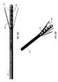
- FIGS. 2 and 3 illustrate the leadless stimulator 100 .
- the antenna 200 is in a wrapped configuration, and in FIG. 3 the antenna 200 is in an outstretched configuration.
- the leadless stimulator 100 can include a stimulation capsule 120 , a tether 190 , and an antenna 200 .
- the stimulation capsule 120 can include a plurality of electrodes and can record and/or stimulate the neurological tissue into which it is implanted.
- the leadless stimulator 100 also includes an antenna 200 that can be coupled to the stimulation capsule 120 with the tether 190 .
- the tether 190 can provide a mechanical and electrical coupling between the antenna 200 and the stimulation capsule 120 .
- the antenna 200 is reversibly coupled with the tether 190 and in other implementations the antenna 200 is permanently coupled with the tether 190 .
- the tether 190 and the antenna 200 refer to the same part of the leadless stimulator 100 .
- the part of the antenna outside of the patient may be referred to as the antenna 200 while the portion of the antenna inside the patient may be referred to as the tether 190 . As illustrated in FIGS.
- the tether 190 and antenna 200 can be flexible.
- the antenna 200 can be configured to be flexible enough to enable the antenna 200 to be coiled within a burr cover that is implanted in the patient's skull or to form a loop as illustrated in FIG. 2 .
- the tether 190 and the antenna 200 have a diameter of about 0.5 mm, but could range from as small as 0.2 mm to as large as 2 mm.
- the wires that form the antenna 200 can form a bifurcated tail body.
- the bifurcated tail body forms an antenna loop.
- the antenna 200 can include a wire coil that is embedded in a flexible, elastomeric body.
- the antenna loop may be flexible enough be stretched over a burr hole cover, which can position the antenna 200 in a predetermined shape (e.g., a loop of a predetermined diameter).
- a predetermined shape e.g., a loop of a predetermined diameter
- the antenna 200 may be wound into a circular loop of the predetermined diameter.
- the below discussed burr hole cover frame may be used to ensure the antenna 200 maintains the predetermined diameter.
- the predetermined diameter of the antenna can enable the efficient coupling of antenna 200 and the external antenna 540 of the external programmer 500 .
- the leadless stimulator 100 communicates wirelessly with the external programmer 500 over the 27 MHz frequency.
- Other frequencies which could be used are any of those determined by the International Telecommunication Union Radiocommunication Sector (ITU-R) in their reserved Industrial, Scientific, and Medical (ISM) Bands such as for example, but not limited to, 6.780 Mhz, 13.560 MHz, 40.680 MHz, 2.450 GHz, 5.80 GHz.
- the antenna diameter can be inversely proportional to the wavelength of the signal the antenna 200 transmits over. For example, with a 27 MHz frequency the loop diameter of the antenna 200 can be about 25 mm in diameter. In general, the loop diameter of the antenna is about half the wavelength of the frequency used to communicate with the antenna.
- FIG. 4 illustrates an enlarged view of the distal end of the leadless stimulator 100 from FIGS. 1-3 .
- the stimulation capsule 120 is coupled with the tether 190 at the proximal end 127 of the capsule body 125 .
- the capsule body 125 can be conical or cylindrical in shape.
- the proximal end 127 can mate with the distal end of a cannula (not illustrated) during the implantation procedure.
- the capsule body 125 includes a polymeric material and houses the active electronic components of the leadless stimulator 100 .
- electronic components may also be housed in the tether 190 and antenna 200 .
- the stimulation capsule 120 can include a hemispherical distal tip 126 .
- the distal tip 126 can include electronic components. These electronic components are generally integrated circuits, resistors, capacitors, or a combination thereof.
- the stimulation capsule 120 can be cylindrical and have a larger diameter than the tether 190 .
- the diameter of the stimulation capsule 120 is between about 0.3 mm and about 3 mm, between about 0.75 mm and about 2.5 mm, between about 1 mm and about 2 mm, or between about 1.2 mm and about 1.6 mm.
- the stimulation capsule 120 can also include a MEMS film 150 .
- the MEMS film 150 can manufactured as a substantially planar film, which is coupled around the capsule body 125 . In some implementations, the MEMS film 150 is wrapped to form a cylindrical shape and then glued or co-molded into place.
- the MEMS film 150 can include one or more electrodes 160 . As illustrated in FIG. 4 , the MEMS film 150 includes twelve electrodes (only eight of the electrodes 160 are visible in FIG. 4 ).
- the electrodes 160 can be implemented in a noble metal, such as platinum.
- the electrodes 160 can be implemented in gold, titanium, iridium oxide, platinum grey, platinum black, and oxides of titanium. As illustrated the electrodes 160 substantially square with rounded corners. In some implementations, the electrodes 160 can be circular, rectangular, or any other shape. In some implementations, the electrodes 160 can be used for physiological recordings and simulations.
- FIGS. 5 and 6 illustrate the MEMS film 150 in its substantially planar configuration.
- the MEMS film 150 includes twelve electrodes 160 disposed across the exterior portion 157 of the MEMS film 150 .
- the MEMS film 150 has about 4, 6, 8, 12, 16, 24, 36, 48, 64, or more electrodes 160 .
- the electrodes 160 can be arranged in specific patterns.
- FIGS. 5 and 6 illustrate an electrode arrangement that includes three columns and four rows of electrodes 160 .
- the electrodes 160 can be rectangular electrodes that span the width of the exterior portion 157 and form ring electrodes when the MEMS film 150 is rolled into its cylindrical shape.
- the MEMS film 150 also includes a ribbon cable 165 .
- the lower portion of the ribbon cable 165 includes the contact pad 175 .
- the contact pad 175 includes a plurality of contacts 170 .
- Each of the contacts 170 can be coupled with one or more of the electrodes 160 through traces embedded within the MEMS film 150 .
- the MEMS film 150 may include twelve electrodes 160 and twelve contacts 170 .
- each of the contacts 170 may be coupled with a different one of the twelve electrodes 160 .
- the contact pad 175 may include fewer contacts 170 than electrodes 160 .
- one or more electrodes 160 may be coupled with the same contact 170 , such that they may be stimulated (or recorded from) as a single unit.
- the contact pad 175 includes contacts 170 configured for different purposes.
- the contact pad 175 illustrated in FIGS. 5 and 6 includes a second type of contacts—the wire tether contacts 172 .
- the different types of contacts are generally referred to as contacts 170 .
- the wire tether contacts 172 are used to couple the MEMS film 150 to the wires of the tether 190 and antenna 200 .
- the contacts 170 may be coupled to an application-specific integrated circuit (ASIC) or other electronic component that is housed within the stimulation capsule 120 .
- ASIC application-specific integrated circuit
- FIG. 7 illustrates an enlarged view of the contact pad 175 from FIGS. 5 and 6 .
- a metal layer 174 is deposited on the contacts 170 .
- the metal layer 174 can include gold or other metal such as platinum, titanium, or copper.
- the addition of a metal layer 174 increases the ease of welding or attaching electronic components (e.g., antenna wires) to the contacts 170 .
- the metal layer 174 improves the contacts' 170 ability to go undergo flip-chip bonding. The improvement in creating a contact with the contacts 170 may be caused by the metal layer 174 rising above the polyimide surface of the contact pad 175 , making it easier for electronic components to be coupled to the contacts 170 .
- FIGS. 8-13 illustrate the assembly of an example contact pad 175 .
- FIG. 8 illustrates an ASIC 180 prior to its coupling with the contact pad 175 .
- the internal electronics of the stimulation capsule 120 are coupled to the contact pad 175 .
- a single ASIC 180 is coupled with the contact pad 175 ; however, the electronic components of the leadless stimulator 100 can be divided among a plurality of ASICs 180 , batteries, passive electronic components (e.g., resistors and capacitors), or other electronic components.
- the ASIC 180 includes a plurality of contacts 170 , which are bound to the contacts 170 of the contact pad 175 .
- the contacts 170 of the ASIC 180 can have the same pitch (e.g., spacing) as the pitch of the contact pad 175 , such that the contacts 170 align and can be coupled together.
- the ASIC 180 is coupled with the contact pad 175 when the MEMS film 150 is a planar configuration—prior to the MEMS film 150 being formed into a cylindrical (or other) shape.
- the ASIC 180 may be coupled with the contact pad 175 prior to the contact pad 175 being removed from the substrate on which it was fabricated.
- the ASIC 180 can be thinned to a thickness of about 50 ⁇ m, and generally has a thickness between about 20 and about 550 ⁇ m, prior to the ASIC 180 being coupled with the contact pad 175 .
- the ASIC 180 includes the stimulation source that is used to stimulate tissue via the electrodes 160 .
- the ASIC 180 can also include a recording circuit.
- the stimulation capsule includes a plurality of ASIC 180 .
- FIG. 10 illustrates the lead wires 192 coupled with the contact pad 175 .
- One or more lead wires 192 can be coupled to the one or more wire tether contacts 172 .
- the lead wires 192 can be electrically coupled with the antenna 200 through the tether 190 .
- the lead wires 192 can include platinum-iridium wire, and have a thin electrically isolating coating.
- Incoming signals from the antenna 200 can be transmitted to the ASIC 180 .
- the ASIC 180 can process these signals and record and stimulate through the electrodes 160 as instructed by the signals.
- the ASIC 180 can also transmit captured neural signals to a computer or other external device through by a transmission the signals over the antenna 200 .
- the MEMS film 150 can be molded into a cylindrical shape.
- FIG. 11 illustrates the MEMS film 150 molded into a cylindrical shape.
- the shaping of the MEMS film 150 into a non-planar shape can be performed by heat molding the MEMS film 150 while protecting the mounted ASIC 180 or by molding the ASIC 180 in place.
- the contact pad 175 is toward the MEMS film 150 .
- the exterior portion 157 can then be rolled around the contact pad 175 , such that the contact pad 175 with its coupled ASIC 180 (e.g., the stimulation source, the power supply, and the recording circuit) is within a lumen created by the rolled exterior portion 157 .
- ASIC 180 e.g., the stimulation source, the power supply, and the recording circuit
- FIG. 12 illustrates a cutaway view of the MEMS film 150 molded into a cylindrical shape.
- FIG. 12 illustrates the folding of the MEMS film 150 into a cylindrical and the internal electronics of the MEMS film 150 .
- the ribbon cable 165 can be folded back such that the contact pad 175 at least partially overlaps the exterior portion 157 .
- the edges of the exterior portion 157 are then rolled to create a cylinder around the ASIC 180 .
- the created cylinder can be co-molded to create the leadless stimulator 100 .
- FIG. 13 illustrates an enlarged view of an example stimulation capsule 120 .
- the rolled MEMS film 150 can be over-molded to create a mechanically stable device.
- the MEMS film 150 is rolled to create the cylindrical shape.
- the capsule body 125 of the leadless stimulator 100 is then manufactured by co-molding the MEMS film 150 to encapsulate the interior of the MEMS film 150 and the electronics therein.
- the co-molding of the MEMS film 150 can involve securing the MEMS film 150 in place and having it back-filled with a polymer precursor, such as an epoxy, to backfill the cavities within the molded MEMS film 150 .
- a polymer precursor such as an epoxy
- the over-molding material may include epoxy materials, such as EPO-Tek 353, that provide sealing of the electronics and wire traces therein, protecting the electronics from body fluids that may disrupt electrical function.
- the stimulation capsule 120 can also include a distal tip 126 .
- the distal tip 126 can be coupled with the capsule body 125 or the distal tip 126 can be created as part of the capsule body 125 during the over-molding process. As illustrated the distal tip 126 is hemispherical, although other shapes may be used. For example, the distal tip 126 can be beveled or blunt. The distal tip 126 enables atraumatic insertion of the leadless stimulator 100 into tissue during the implantation procedure.
- FIG. 13 also illustrates the tether 190 .
- the tether 190 can include a jacket, such as a polymeric tubing, around the lead wires 192 .
- the tether 190 can be hollow and have a lumen through which the lead wires 192 run.
- the tether 190 can be filled, encapsulating the lead wires 192 or other electronic components in the lumen of the tether 190 .
- the tether 190 is of a diameter of 0.5 mm, is flexible and easily wraps around a finger of a surgeon for example.
- the leadless stimulator 100 may not include an antenna 200 at the surface of the skull.
- the leadless stimulator 100 may include an integrated antenna (also referred to as a micro-antenna) on the stimulation capsule 120 .
- An integrated antenna can reduce the risk of malfunction due to broken lead wires.
- FIG. 14 illustrates an example leadless stimulator 100 with a micro-antenna.
- the leadless stimulator 100 with a micro-antenna can include a stimulation capsule 120 and a tether 190 .
- the tether 190 may not include lead wires to form an antenna; however, the leadless stimulator 100 may still include the tether 190 to facilitate the removal of the leadless stimulator 100 from a patient's tissue after implantation.
- FIGS. 15 and 16 illustrate an example MEMS film 150 with a micro-antenna.
- the MEMS film 150 can include an exterior portion 157 , a ribbon cable 165 , and contacts 170 .
- the exterior portion 157 includes nine electrodes 160 and a micro-antenna 661 . In some implementations, the exterior portion 157 includes more than or fewer than nine electrodes 160 .
- the contact pad 175 includes a battery pad 684 , on which a battery may be coupled.
- the battery may be coupled with the battery pad 684 in a means (e.g., flip chip bonding) similar to the means that an ASIC 180 is coupled to the contact pad 175 .
- the battery pad 684 can be folded over on the contacts 170 of the contact pad 175 .
- the ribbon cable 165 is divided into two separate ribbon cables.
- the metal layer of the MEMS film 150 that includes the traces from the electrodes 160 to the contacts 170 and the micro-antenna 661 is covered by a top insulating layer to electrically insulate the components.
- FIG. 16 illustrates an enlarged view of the example MEMS film 150 from FIG. 15 .
- the top insulating layer of the MEMS film 150 is removed to illustrate the electrical elements embedded within the MEMS film 150 .
- removal of the top insulating layer exposes the micro-antenna 661 and the electrical traces 658 .
- the electrical traces couple the electrodes 160 with the contacts 170 (or other electrodes 160 ).
- the micro-antenna 661 is embedded in the metal layer of the MEMS film 150 .
- the micro-antenna 661 is serpentine in shape and is designed in order to be highly efficient at the chosen transmission frequencies.
- FIG. 17 illustrates a perspective view of an example leadless stimulator 100 with a micro-antenna 661 .
- the MEMS film 150 can be rolled into a cylindrical shape.
- the MEMS film 150 can then be over-molded to create a capsule body 125 .
- the tether 190 does not include antenna wires, and the tether 190 is used for the extraction of the leadless stimulator 100 from a patient after implantation.
- the tether 190 is embedded within the distal tip 126 . Having the tether 190 run through the length of the body can reduce the chance of the tether 190 breaking free of the stimulation capsule 120 .
- FIGS. 18 and 19 illustrate a cutaway view of an example leadless stimulator 100 with micro-antenna 661 .
- the tether 190 can be coupled to the distal tip 126 .
- FIG. 18 illustrates that the tether 190 passes through the body of the stimulation capsule 120 and is coupled with the distal tip 126 .
- the ribbon cable 165 is divided into two parts (ribbon cable 165 A and ribbon cable 165 B) to facilitate the passage of the tether 190 through the capsule body 125 .
- the tether 190 can pass between the two parts of the ribbon cable 165 .
- FIGS. 18 and 19 also illustrate the placement of the power supply 181 .
- the power supply 181 is a battery.
- the power supply 181 may be recharged by the external programmer 500 .
- the power supply 181 can have enough charge to provide stimulation for at least one day, or about 200 mAh, and in some implementations up to several weeks, or around 2300 mAh.
- FIGS. 20A and 20B illustrate the internal arrangement of an example leadless stimulator 100 with a micro-antenna.
- the contacts 170 of the ASIC 180 can be aligned with and bonded to the respective contacts 170 of the contact pad 175 .
- the contacts 170 of the power supply 181 can be aligned with and bonded to the respective contacts 170 of the battery pad 684 .
- the ASIC 180 (or other components) can be wire bonded to the MEMS film 150 through wire bonds.
- the power supply 181 and the ASIC 180 are placed on opposite sides of the tether 190 as the tether 190 passes through the body of the stimulation capsule 120 .
- FIGS. 21 and 22 illustrate an example MEMS film 150 with a micro-antenna 661 .
- the MEMS film 150 includes a micro-antenna 661 on the distal portion of the contact pad 175 .
- the micro-antenna 661 is disposed on a projection 176 from the contact pad 175 .
- the micro-antenna 661 can be rolled to form a loop, which is housed within the rolled MEMS film 150 .
- FIG. 22 illustrates a cutaway view of the stimulation capsule 120 with the rolled micro-antenna 661 located in the internal portion created by the rolled MEMS film 150 .
- FIGS. 23A-23M illustrate a cross-sectional view of an example thin-film micro-fabrication method for fabricating the MEMS film 150 .
- the MEMS film 150 can be fabricated using a plurality of techniques and the below describe method illustrates one possible method for fabricating the MEMS film 150 .
- the fabrication procedure can include a series of procedural steps in which various layers are deposited or removed (e.g., etched) to achieve a final form.
- the cross sections in FIG. 23A through FIG. 23M demonstrate the process steps to build a MEMS film 150 .
- a carrier substrate 2301 is provided, such as a wafer composed of a crystalline material, such as silicon, or an amorphous material, such as a thermal shock resistant borosilicate glass or other suitable smooth supportive material.
- a first layer 2302 which can include one or more sub-layers, is applied to a surface of the wafer 2301 .
- One of the sub-layers can be a sacrificial layer deposited on the wafer 2301 , which is removed in a subsequent electrochemical etching step.
- the sacrificial sub-layer is preceded by another sub-layer, referred to as an underlayer, which can serve to form the electrochemical cell required to etch the sacrificial layer.
- the sacrificial sub-layer can be aluminum, or an alloy of aluminum such as AlSi, which has a smaller granularity, whereas the underlayer can be a TiW alloy such as Chrome or similar metal.
- the next step in the fabrication process can include depositing a first polymeric layer 2305 .
- the first polymeric layer 2305 can be deposited upon the sacrificial layer 2302 by MEMS processes such as, but not limited to, (i) spin coating a liquid polymer precursor such as Polyimide or Silicone precursor; (ii) depositing a polymer through chemical vapor deposition as is done with parylene-C; or (iii) laminating a polymer sheet onto the wafer.
- the polymer layer 2305 is heated, or baked, to polymerize.
- the first polymeric layer 2305 includes polyamic-acid dissolved in NMP and spun onto the sacrificial layer 2302 in liquid form.
- the polymeric layer 2305 is heated into a imidized polyimide.
- the polymer in its cured form is between about 5 ⁇ m and about 15 ⁇ m thick.
- the barrier layer can serve both as a layer to aid the adhesion and durability of subsequent layers.
- the barrier layer can also serve as an ionic barrier, and limit ions from reaching the metal layers, which could compromise electrical performance.
- the barrier layer can also block humidity from reaching the interlayers and the metal layer, which could create short circuits and compromise electrical isolation.
- the barrier layer is deposited onto the first polymeric layer 2305 by vapor deposition techniques such as chemical vapor deposition (CV) and plasma enhanced chemical vapor deposition (PECVD), or by sputtering techniques such as direct current (DC) or RF (Radio Frequency) sputtering.
- the barrier layer can include Silicon Nitride, Silicon Oxide, Silicon Carbide, Poly-Silicon, or Amorphous-Silicon.
- the barrier layer can also include other non-conductive materials, such as Titanium Dioxide or Titanium (III) Oxide.
- the final thickness of the barrier layer can range from about 100 nm to about 2 ⁇ m. In some implementations, the barrier layer is about 400 nm to about 600 nm, which can permit the barrier layer to be flexible enough to bend during subsequent assembly techniques.
- a metal layer 2315 can be deposited over the entire wafer on the surface of the barrier layer 2310 .
- a photoresist layer 2317 can be deposited.
- the photoresist layer 2317 can be defined by exposing areas of the photoresist layer 2317 to ultra-violet light and developing those areas in a solvent. Thus, the exposed areas of the photoresist layer 2317 will be selectively removed and areas of the metal layer 2315 will be exposed.
- the areas of the metal layer 2315 covered by the photoresist layer 2317 can form the electrodes, traces, and other components of the final product that are within the metal layer.
- the metal layer 2315 can include a variety of metals such as titanium, platinum, gold, and others metals used in neuromodulation. To improve adhesion of a metal layer 2315 , the metal layer 2315 can be applied in layers. For example, the metal layer 2315 can be applied as a first layer, such as titanium, then a middle layer, such as platinum, and finally an upper layer, such as titanium. This tri-layer metal structure can improve adhesion below and above the platinum layer by using the titanium as an adhesion layer to the barrier layer.
- the typical thicknesses for the adhesion layer of titanium can be between about 20 nm and about 100 nm or between about 25 nm and about 75 nm.
- Typical thicknesses for the platinum layer can be between about 200 nm and about 400 nm or between about 250 nm and about 350 nm.
- FIG. 23E illustrates the process after the etching of the metal layer 2315 .
- the metal layer 2315 can be locally removed in the areas that were not covered by the photoresist 2317 .
- etching of the metal layer is performed in a plasma etcher such as a Reactive Ion Etcher.
- titanium and platinum can be etched with chlorine gas.
- the photoresist layer 2317 can be removed using a solvent.
- Another method to deposit and define the metal layer is using the so-called “lift off” technique.
- the photoresist layer can be deposited onto the barrier layer 2310 first.
- the photoresist layer can be defined using photolithography.
- the metal layer 2315 can then be deposited through this “lift off” mask, and the remaining photoresist removed in a solvent.
- the metal layer is transferred onto the barrier layer without the need of plasma etching and may have some process costs and speed advantages.
- a deposition of a second barrier layer 2320 is performed.
- the second barrier layer can be deposited using the same techniques as the first barrier layer 2310 .
- the second barrier layer 2320 can be the same thickness, or a different thickness as the first barrier layer. In some implementations, the second barrier layer is optional.
- the second barrier layer 2320 and the first barrier layer 2310 can substantially surround the metal layer 2315 , rendering it electrically isolated.
- a second photoresist layer 2327 is deposited and photolithographically defined with clean room techniques.
- the two barrier layers are etched, as illustrated in FIG. 23G .
- the barrier layers can be etched using a plasma etch.
- An example of an etching process would be a reactive ion etching using a tetrafluoromethane gas, (CF4).
- the second photoresist layer 2327 can be removed using a solvent dissolution.
- FIG. 23G illustrates that the edges of the barrier layers 2310 and 2320 are defined, but the etch does not reach the metal layer 2315 .
- the photolithography can include an opening above the metal layer 2315 , which would result in exposing the metal layer 2315 .
- FIG. 23H illustrates the application of a second polymer layer 2330 .
- the second polymer layer 2330 can be the same or a different polymer from the first polymer layer 2305 , and it can be the same or a different thickness.
- FIG. 23I illustrates the deposition of a third photoresist 2337 , which can form the etching perimeter of the first and second polyimide layers 2305 and 2330 , respectively.
- a sacrificial layer such as Silicon Dioxide or Silicon Nitride, is deposited in order to serve as an etch mask for the polyimide etch.
- a silicon dioxide layer of thickness of about 500 nm can be deposited, which will serve as the etch mask for the process.
- FIG. 23J illustrates the result of an oxygen plasma etching of the first and second polyimide layers 2305 and 2330 , respectively. If applied, the silicon dioxide layer can be removed through an additional etch.
- FIG. 23K illustrates the deposition of a fourth photoresist layer 2347 .
- the fourth photoresist layer 2347 does not cover part of the metal layer 2315 .
- the opening 2332 maintained is designed to create a region for a gold layer to grow.
- FIG. 23L illustrates the galvanic growth of a thick gold layer 2350 into the opening 2332 .
- the gold layer 2350 is achieved by connecting the metal traces in the wafer to a perimetric metal band that allows an electrical connection between the edge of the wafer and the metal opening 2332 .
- the gold will grow on the metal layer 2315 using the metal layer 2315 as the seed layer for galvanic growth.
- the gold layer 2350 is about 2 ⁇ m to about 20 ⁇ m thick.
- the fourth photoresist layer 2347 can be removed using a solvent.
- FIG. 23M illustrates the removal of the MEMS film from the wafer 2301 .
- the removal of the fourth photoresist layer 2347 exposes the electrode opening 2333 .
- the MEMS film can be removed from the wafer 2301 by the removal of the sacrificial layer 2302 using electrochemically etching. Removal of the sacrificial layer 2301 frees the underside of the MEMS film from the wafer 2301 .
- the sacrificial layer 2301 is removed by placing the wafer in a saline bath with a high NaCl concentration. A platinum electrode also placed in the bath can be used as a reference, and a voltage can be applied to the aluminum layer with respect to the platinum electrode.
- the electrochemical cell created by the aluminum and TiW etches the aluminum—separating the MEMS film from the wafer 2301 .
- FIG. 23N illustrates a method 2360 for manufacturing a leadless stimulator.
- a MEMS film is formed.
- the method for forming the MEMS film is described above in relation to FIGS. 23A-23M .
- the MEMS film is formed as a planar film.
- the MEMS film can include a plurality of electrodes and a ribbon cable that extends from the distal end of the MEMS film.
- a stimulation source is coupled with the MEMS film.
- the stimulation source may be a component of an ASIC 180 .
- the stimulation source (or ASIC 180 ) can include a plurality of contacts 170 .
- the ribbon cable can also include a plurality of contacts 170 .
- the contacts 170 of the ASIC 180 can be coupled with the contacts 170 of the ribbon cable. Coupling the contacts 170 of the ASIC 180 with the contacts 170 of the ribbon cable can enable an electrical connection between the ASIC 180 and one or more electrodes.
- a power supply is coupled with the MEMS film.
- a power supply 181 can be coupled with the MEMS film.
- the power supply can include a plurality of contacts, through which an electrical connection is established with the MEMS film.
- the power supply is coupled to the same face of the ribbon cable as the stimulation source, and in other implementations the power supply is coupled with a face opposite to the face the stimulation source is coupled.
- other circuitry such as recording circuitry, control circuitry, or other ASICs can be coupled with the ribbon cable.
- the ribbon cable is folded toward a face of the MEMS film.
- the ribbon cable 165 with the coupled stimulation source and power supply, are folded toward a face of the MEMS film.
- the MEMS film can include two primary faces. The first face includes the plurality of electrodes and the second face is the opposite face of the MEMS film. As illustrated in FIG. 12 , the ribbon cable 165 is folded toward the second face of the MEMS film.
- the MEMS film is formed into a lumen. Also as illustrated in FIG. 12 , the sides of the MEMS film are formed around the portion of the ribbon cable to which the stimulation source and power supply are coupled. The formed MEMS film defines a lumen, in which the stimulation source and power supply are disposed. The MEMS film can be heat formed such that the MEMS film maintains it shape after the forming process. In some implementations, the lumen defined by the formed MEMS film is filled with an encapsulating epoxy. The encapsulating epoxy can provide structural stability to the stimulation capsule and can also electrically isolate the electrical components disposed within the lumen.
- FIG. 24 illustrates an example deployment system 305 .
- the deployment system 305 is used to implant the leadless stimulator 100 .
- the deployment system 305 includes a guide tube 300 .
- deployment system 305 can include a connection plug 310 .
- the connection plug 310 enables electrical connections between the deployment system 305 and a controller or recording device used during the implantation of the leadless stimulator 100 .
- the connection plug 310 is coupled with the other components of the deployment system 305 via the connection cable 315 .
- the connection cable 315 can include electrical conductors, in the form of wires or traces, which electrically couple the distal electrodes 355 to the connection plug 310 .
- the deployment system 305 also includes a depth stop 320 to enable the surgeon to couple the deployment system 305 with stereotactic equipment.
- the depth stop 320 may also house pre-amplifier circuitry to improve the signals coming from the distal electrodes 355 .
- the depth stop 320 also includes a deployment handle 325 .
- the deployment handle 325 may be pushed up or down by the surgeon to deploy or retract, respectively, the distal legs 360 . In FIG. 24 , the distal legs 360 are illustrated in the deployed state.
- the body of the deployment system 305 includes guide tube 300 .
- the guide tube 300 can include a leg support stent that is disposed around an inner cylinder.
- a MEMS film can be disposed around the leg support stent to form the distal legs 360 .
- FIGS. 25A and 25B illustrate a cut away and perspective view, respectively, of the distal end of the guide tube 300 .
- the inner cylinder 330 includes a central lumen 337 .
- the distal most end of the inner cylinder 330 includes a guide 339 .
- the guide 339 can mate with the proximal end of the stimulation capsule 120 .
- the external diameter of the inner cylinder 330 is between about 0.5 mm and about 3 mm, between about 1 mm and about 2 mm, or about 1 mm and 1.5 mm.
- the internal diameter of the central lumen 337 is between about 0.25 mm and about 1.5 mm or between about 0.5 mm and about 1 mm.
- the internal diameter of the central lumen 337 can enable the insertion of the tether 190 and the antenna 200 .
- the guide 339 can have a slightly larger external diameter when compared to the inner cylinder 330 .
- the diameter of the guide 339 may be about 1.5 mm when the outer diameter of the inner cylinder 330 is about 1 mm.
- the guide 339 can either be a separate piece, which is later coupled with the inner cylinder 330 , or the guide 339 can be machined from the same stock material as the inner cylinder 330 .
- the inner wall 340 of the guide 339 can surround the leadless stimulator 100 , and the outer wall 341 of the guide 339 can be used to guide the below described distal legs 360 during deployment.
- the inner cylinder 330 includes a metal, such as surgical stainless steel, and in other implementations, the inner cylinder 330 can include a polymer or other MRI compatible material such as a ceramic or titanium oxide.
- FIGS. 26A-26C illustrate an example leg support stent 344 .
- the external diameter of the leg support stent 344 is between about 0.5 mm and about 3 mm, between about 1 mm and about 2 mm, or about 1 mm and 1.85 mm.
- the internal diameter of the leg support stent 344 can be at least the external diameter of the inner cylinder 330 , such that the leg support stent 344 can be disposed around the inner cylinder 330 .
- the leg support stent 344 can include leg supports 342 at distal end of the leg support stent 344 . As illustrated, the leg support stent 344 includes four leg supports 342 .
- the leg supports 342 can be flexible enough to expand with the typical forces that can be applied by hand.
- FIG. 26B and 26C illustrate the expanded leg supports 342 .
- the leg supports 342 of the leg support stent 344 slide distally along the inner cylinder 330 . When the leg supports 342 come into contact with the outer wall 341 of the guide 339 , the outer wall 341 can cause the leg supports 342 to expand.
- FIG. 27 illustrates an example MEMS film 350 that can be coupled around the leg support stent 344 .
- the MEMS film 350 can include legs 352 .
- the MEMS film 150 includes four legs 352 .
- the legs 352 are between about 5 mm and about 15 mm or between about 7 and about 12 mm in length.
- the legs 352 can be about 0.25 mm to about 1 mm in width.
- the legs 352 are about the same length and width as the leg supports 342 .
- One or more surfaces of the legs 352 can include a plurality of microelectrode elements 355 . As illustrated, each leg 352 includes five microelectrode elements 355 .
- different legs 352 can include a different number of microelectrode elements 355 .
- Each microelectrode elements 355 can include between 1 and about 10 microelectrode elements 355 .
- the legs 352 include more than 10 microelectrode elements 355 .
- the microelectrode elements 355 can be circular or rectangular in shape and have a diameter between about 100 ⁇ m and about 1000 ⁇ m, or between about 200 ⁇ m and about 700 ⁇ m, or between about 300 ⁇ m and about 500 ⁇ m.
- the MEMS film 350 can also include a shoulder 357 that can be coupled around the leg support stent 344 .
- the MEMS film 350 can further include a tether 359 , which carries traces from the microelectrode elements 355 to the proximal end of the guide tube 300 .
- a tether 359 which carries traces from the microelectrode elements 355 to the proximal end of the guide tube 300 .
- FIG. 28A illustrates the MEMS film 350 coupled with the leg support stent 344 .
- the MEMS film 350 can be coupled to the leg support stent 344 with glue or pressure bonding.
- the legs 352 are aligned and coupled with the leg supports 342 .
- FIG. 28B illustrates the MEMS film 150 coupled with the leg support stent 344 , with the leg supports 342 in the retracted state.
- FIG. 29A illustrates an example outer tube 370 of the guide tube 300 .
- the distal end of the outer tube 370 can include leg gaps 372 .
- the outer tube 370 can enable the leg supports 342 to fit within the leg gaps 372 .
- the outer tube 370 can have an outer diameter between about 0.5 and about 2.5 mm.
- the wall thickness of the outer tube 370 is about 0.2 mm.
- the outer tube 370 is generally implemented in a medical grade Stainless Steel such as 316 , or could be implemented in a polymer such as polyimide to promote improved MRI Compatibility.
- FIG. 29B illustrates an example guide tube 300 with an outer tube 370 in place.
- the outer tube 370 can be placed concentrically over the MEMS film 350 and the leg support stent 344 .
- the assembly guide tube 300 exposes the microelectrode elements 355 through the leg gaps 372 of the outer tube 370 .
- exposure of the microelectrode elements 355 through the leg gaps 372 enables the microelectrode elements 355 to record neural activity as the guide tube 300 descends into brain tissue.
- the guide tube 300 can perform neural recording to enable a surgeon to identify the guide tube's location with a patient's tissue.
- FIGS. 30A and 30B illustrate two views of the guide tube 300 with the distal legs 360 deployed.
- the distal legs 360 can be deployed by a surgeon to perform neural recording.
- Each of the distal legs 360 can include a plurality of microelectrode elements 355 .
- each of the four distal legs 360 include five microelectrode elements 355 , for a total of twenty recording and stimulation sites.
- the guide tube 300 can include more or fewer distal legs 360 , each with more or fewer microelectrode elements 355 .
- FIGS. 31A and 31B illustrate an example deployment mechanism 319 .
- the deployment mechanism 319 can include a handle 325 that can be used to deploy the distal legs 360 , as illustrated in FIGS. 30A and 30B .
- the leg support stent 344 can be attached to the deployment handle 325 . Accordingly, movement of the deployment handle 325 can be translated into movement of the leg support stent 344 , which results in the deployment or retraction of the distal legs 360 .
- FIG. 31A illustrates the position of the deployment handle 325 when the distal legs 360 are in the deployed state
- FIG. 31B illustrates the position of the deployment handle 325 when the distal legs 360 are in the retracted state.
- the central lumen 337 is visible on the proximal end of the deployment mechanism 319 .
- the deployment mechanism 319 can include depth stops 320 that can limit the movement of the deployment handle 325 in the proximal and distal directions.
- FIGS. 32A and 32B illustrate the distal end of the example deployment system 305 coupled with the leadless stimulator 100 .
- the deployment system 305 includes the guide tube 300 coupled with the leadless stimulator 100 .
- the stimulation capsule 120 is exposed at the distal end of the guide tube 300 .
- the proximal end 127 of the leadless stimulator 100 (hidden in FIGS. 32A and 32B ) can couple with the guide 339 (hidden in FIGS. 32A and 32B ) of the guide tube 300 .
- the guide tube 300 can be used to push the leadless stimulator 100 toward the target location in the tissue.
- FIGS. 33A and 33B illustrate the distal end of the example deployment system 305 , with the distal legs 360 deployed.
- the distal legs 360 when deployed, can enable the recording and stimulation of the region surrounding the stimulation capsule 120 .
- the intra-operative recording and stimulation procedure can be used to further determine the final position of the leadless stimulator 100 .
- the recording and stimulation procedure can be used to determine an improved stimulation and recording configuration for the leadless stimulator 100 .
- the procedure may be used to determine if a subset of the electrodes 160 of the leadless stimulator 100 should be used for recording and stimulating.
- FIGS. 34A and 34B illustrate the distal end of the example deployment system 305 , with the guide tube 300 and stimulation capsule 120 separated—for example, after the surgeon has begun to retract the deployment system 305 from the patient's tissue.
- the distal legs 360 are retracted and then the deployment system 305 can be retracted from the tissue, leaving, as illustrated in FIGS. 34A and 34B , the leadless stimulator 100 at the target location.
- FIGS. 35-38 illustrate an example method of implanting the leadless stimulator 100 .
- FIG. 35A and 35B illustrate the leadless stimulator 100 in the preimplantation position.
- the leadless stimulator 100 is positioned above a craniotomy 1055 in a patient's skull 1050 .
- the craniotomy exposes a portion of the brain 1060 .
- the leadless stimulator 100 and deployment system 305 are lowered into place from the exterior of the patient using stereotactic implantation tools (not illustrated).
- FIGS. 36A and 36B illustrate the positioning of the leadless stimulator 100 into the patient's brain 1060 .
- the surgeon drives the deployment system 305 into the patient's brain 1060 , which in turn pushes the leadless stimulator 100 into the position.
- the surgeon can record neural activity as with the deployment system 305 and leadless stimulator 100 as they are lowered toward the target location.
- FIGS. 37A and 37B illustrate the deployment of the distal legs 360 of the leadless stimulator 100 .
- the distal legs 360 are deployed to record neural activity when the leadless stimulator 100 is believed to be at the proper implantation location.
- the microelectrode elements 355 of the guide tube 300 , and optionally the electrodes 160 of the leadless stimulator 100 can be used to record the neural activity of the implanted location. This procedure may be referred to as “targeting.” Targeting procedure may include recording the electrical activity of the target anatomy using the microelectrode elements 355 and the electrodes 160 .
- a signal processing software can record and display the neural activity to the neurosurgical team.
- the team may determine if the leadless stimulator 100 is placed in the proper anatomical location.
- the microelectrode elements 355 and the electrodes 160 can be used to stimulate the anatomical target in order to evoke a physiological response in the patient—for example, eye twitching or parasthesia. This procedure of neurophysiological recording and evoked patient responses can lead the neurosurgical team to determine the best placement of the leadless stimulator 100 .
- FIGS. 38A and 38B illustrate the placement of the leadless stimulator 100 after the retraction of the deployment system 305 .
- the distal legs 360 can be retracted.
- the leadless stimulator 100 can be left in place and the deployment system 305 is retracted from the patient.
- the stimulation capsule 120 remains in place and is tethered with the antenna 200 by the tether 190 .
- the antenna 200 may exit the patient through the craniotomy 1055 .
- the surgeon may fill the craniotomy 1055 with surgical cement or bone paste, which can secure the antenna 200 in place.
- the antenna 200 is wound into a burr hole cover frame to secure and position the antenna 200 .
- FIG. 39 illustrates a patient 1000 with a burr hole cover frame 400 in place.
- FIG. 40 illustrates a closer view of the example burr hole cover frame 400 .
- the burr hole cover frame 400 can include a burr hole cover cap 450 that protects the antenna 200 and area of the skull where the craniotomy was performed.
- the burr hole cover frame 400 can also include a lower part 410 .
- the burr hole cover cap 450 can be secured to the lower part 410 by the burr hole cover cap 450 clipping into the lower part 410 .
- the burr hole cover cap 450 can be secured to the lower part 410 by screws 462 through screw holes 456 .
- FIG. 41 illustrates a side view of the example burr hole cover frame 400 after implantation into the craniotomy 1055 .
- the burr hole cover frame 400 can include the burr hole cover cap 450 coupled with the lower part 410 .
- the lower part 410 can include a burr hole insert 412 , through which the leadless stimulator 100 exits the patient.
- the burr hole insert 412 can fill the hole in the skull left by the craniotomy.
- the antenna 200 can wrap around the circumference of the lower part 410 to ensure the antenna 200 maintains a predetermined loop diameter.
- the lower part 410 is secured to the patient by one or more screws 462 or glue.
- FIGS. 42A-42C illustrate the example lower part 410 of the burr hole cover frame 400 .
- FIGS. 42A, 42B, and 42C illustrate side, top, and perspective views of the lower part 410 , respectively.
- the lower part 410 can include a cartwheel frame 415 .
- the cartwheel frame 415 can include an antenna notch 417 around the perimeter of the cartwheel frame 415 .
- the antenna 200 is wound around the perimeter of the cartwheel frame 415 and lies within the antenna notch 417 .
- the antenna notch 417 of the cartwheel frame 415 can include a hole 418 from which the antenna 200 can exit the central lumen 411 of the lower part 410 to be wrapped around the perimeter of the cartwheel frame 415 .
- the lower part 410 can also include a burr hole insert 412 that is inserted into the craniotomy 1055 of the patient.
- the burr hole insert 412 is about 8 mm in diameter in some implementations, but can range from 3 mm to 15 mm in diameter.
- the burr hole insert 412 is about 4 mm deep, but can range from 1 mm to 8 mm deep in some implementations.
- FIG. 42B illustrates that the lower part 410 can include securing screw holes 425 on the inner perimeter of the cartwheel frame 415 and on the spokes 416 of the lower part 410 .
- the securing screw holes 425 can be used to secure the burr hole cover frame 400 to the patient's skull by screwing screws through the securing screw holes 425 and into the patient's skull.
- the lower part 410 can also include screw holes 426 to secure the lower part 410 to the burr hole cover cap 450 .
- the lower part 410 has a diameter 420 of about 25 mm. Generally, the diameter is equivalent to the most efficient antenna diameter for the chosen transmission frequency as described above.
- FIGS. 43A, 43B, and 43C illustrate side, top, and perspective views of the burr hole cover cap 450 , respectively.
- the burr hole cover cap 450 can protect the antenna 200 and the patient's brain after its exposure by the craniotomy.
- the burr hole cover cap 450 can include a smoothed edge 452 .
- the smoothed edge 452 can reduce tissue erosion once implanted.
- the burr hole cover cap 450 can also include three securing screw holes 456 that can align with screw holes 426 .
- FIGS. 44A and 44B illustrate different views of the bottom-side of the burr hole cover cap 450 .
- the burr hole cover cap 450 can include a plurality of alignment guides 458 that are used to align the burr hole cover cap 450 with the lower part 410 before the two components are secured together.
- the burr hole cover cap 450 can also include a central boss 460 that can be used in the alignment of the two components and to plug the central lumen 411 .
- FIGS. 45-47 illustrate the wrapping of the antenna 200 around the lower part 410 .
- FIG. 45 illustrates the lower part 410 and the leadless stimulator 100 after implantation.
- the leadless stimulator 100 is implanted into the patient's brain and the lower part 410 has been inserted into the craniotomy.
- the tether 190 is coupled with the stimulation capsule 120 and extends through the central lumen 411 and transitions into the antenna 200 .
- FIG. 46 illustrates the insertion of antenna 200 into the hole 418 .
- the hole 418 begins in the central lumen 411 and traverses through one of the spokes of the lower part 410 to the antenna notch 417 .
- the antenna 200 can then be wrapped around the lower part 410 in the antenna notch 417 . Wrapping the antenna 200 around lower part 410 can ensure that the antenna 200 forms a loop of proper diameter to increase the effectiveness of the antenna 200 .
- the antenna 200 can be secured to the lower part 410 with a clip or with a bonding agent.
- the proximal end of the antenna 200 includes a loop, which can be stretched over the perimeter of the cartwheel frame 415 and into the antenna notch 417 .
- Deep Brain Stimulation can relieve the symptoms of Movement Disorders.
- the systems and methods described herein provide a more efficient and simple device to deliver the required therapeutic stimulation and in some cases provide neural recording.
- the systems and methods described herein can provide efficient stimulation of the sub-thalamic nucleus, the Globus Pallidus interna, the Globus Pallidus externus, the Zone Incerta, or the Ventral Intermediate Nucleus to relieve symptoms such as rigidity and tremor.
- the systems and devices described herein can be implanted in the Cingulate Gyms 25, the Medial Forebrain Bundle, the Nucleus Accumbens, the Ventral Striatum to deliver electrical stimulation and relieve the symptoms of Depression, Anxiety, Phobias, Obsessive Compulsive Disorder, or Post Traumatic Stress Disorder.
- the leadless stimulator 100 can be implanted into anatomy of the patient other than the brain.
- the leadless stimulator 100 may be used for pain management, spasticity, movement disorders, and spinal cord injury.
- the leadless stimulator 100 can be implanted near the patient's spinal cord.
- FIG. 48A demonstrates a representative human anatomy of the spinal column 4800 .
- the spinal cord 4840 is also represented in the spinal canal 4845 .
- FIG. 48B illustrates a magnified section of the anatomy 4800 demonstrating the same anatomical sections with greater detail.
- FIG. 48C illustrates a perspective view of the anatomy 4800 with four implanted stimulation capsules 120 .
- the implantable antennas 200 remain outside of the epidural space, while the distal ends have been implanted on the surface of the spinal cord.
- FIG. 48D demonstrates the same surgical position from a different viewpoint angle.
- FIG. 48E illustrates a side, cut-away view of the patient's spinal cord.
- the stimulation capsule 120 is implanted dorsal to the spinal cord 1140 , vertebrae 1120 , and the intervertebral discs 1130 .
- FIG. 49 illustrates an example distributed stimulator 900 .
- a plurality of leadless stimulators 100 can be implanted into a patient, and in other implementations a distributed stimulator 900 can be implanted into the patient.
- the distributed stimulator 900 includes a plurality of stimulation capsules 120 (four as illustrated in FIG. 49 ) that can act in unison or similar to a plurality of independently implanted stimulation capsules 120 .
- the stimulation capsules 120 are coupled to a central control device 995 , which can include central antenna for the plurality of stimulation capsules 120 .
- Each of the stimulation capsules 120 are coupled to the central control device 995 by a tether 190 .
- the stimulation capsule 120 includes a plurality of ring electrodes around the circumference of each stimulation capsule 120 .
- FIG. 50 illustrates the example distributed stimulator 900 implanted into a patient.
- the distributed stimulator 900 is implanted into the lumbar region 1210 of the patient.
- the distributed stimulator 900 has been implanted in a region that permits the distributed distal capsules to cover a region which would be advantageous to the surgical procedure, for example, the placement of the stimulation capsules 120 near the patient's spinal column as illustrated in FIG. 48E .
- microelectrode device Various implementations of the microelectrode device have been described herein. These embodiments are giving by way of example and not to limit the scope of the present disclosure. The various features of the embodiments that have been described may be combined in various ways to produce numerous additional embodiments. Moreover, while various materials, dimensions, shapes, implantation locations, etc. have been described for use with disclosed embodiments, others besides those disclosed may be utilized without exceeding the scope of the disclosure.
- Devices described herein as either acute or chronic may be used acutely or chronically. They may be implanted for such periods, such as during a surgery, and then removed. They may be implanted for extended periods, or indefinitely. Any devices described herein as being chronic may also be used acutely.
- any ranges disclosed herein also encompass any and all possible subranges and combinations of subranges thereof. Any listed range can be easily recognized as sufficiently describing and enabling the same range being broken down into at least equal halves, thirds, quarters, fifths, tenths, etc. As a non-limiting example, each range discussed herein can be readily broken down into a lower third, middle third and upper third, etc. Language such as “up to,” “at least,” “greater than,” “less than,” and the like include the number recited and refer to ranges which can be subsequently broken down into subranges as discussed above. Finally, a range includes each individual member.
- One or more or any part thereof of the techniques described herein can be implemented in computer hardware or software, or a combination of both.
- the methods can be implemented in computer programs using standard programming techniques following the method and figures described herein.
- Program code is applied to input data to perform the functions described herein and generate output information.
- the output information is applied to one or more output devices such as a display monitor.
- Each program may be implemented in a high level procedural or object oriented programming language to communicate with a computer system.
- the programs can be implemented in assembly or machine language, if desired. In any case, the language can be a compiled or interpreted language.
- the program can run on dedicated integrated circuits preprogrammed for that purpose.
- Each such computer program can be stored on a storage medium or device (e.g., ROM or magnetic diskette) readable by a general or special purpose programmable computer, for configuring and operating the computer when the storage media or device is read by the computer to perform the procedures described herein.
- the computer program can also reside in cache or main memory during program execution.
- the analysis, preprocessing, and other methods described herein can also be implemented as a computer-readable storage medium, configured with a computer program, where the storage medium so configured causes a computer to operate in a specific and predefined manner to perform the functions described herein.
- the computer readable media is tangible and substantially non-transitory in nature, e.g., such that the recorded information is recorded in a form other than solely as a propagating signal.
- a program product may include a signal bearing medium.
- the signal bearing medium may include one or more instructions that, when executed by, for example, a processor, may provide the functionality described above.
- signal bearing medium may encompass a computer-readable medium, such as, but not limited to, a hard disk drive, a Compact Disc (CD), a Digital Video Disk (DVD), a digital tape, memory, etc.
- the signal bearing medium may encompass a recordable medium , such as, but not limited to, memory, read/write (R/W) CDs, R/W DVDs, etc.
- signal bearing medium may encompass a communications medium such as, but not limited to, a digital or an analog communication medium (e.g., a fiber optic cable, a waveguide, a wired communications link, a wireless communication link, etc.).
- a communications medium such as, but not limited to, a digital or an analog communication medium (e.g., a fiber optic cable, a waveguide, a wired communications link, a wireless communication link, etc.).
- the program product may be conveyed by an RF signal bearing medium, where the signal bearing medium is conveyed by a wireless communications medium (e.g., a wireless communications medium conforming with the IEEE 802.11 standard).
- signals and signal processing techniques may be digital or analog in nature, or combinations thereof.
Abstract
The present disclosure describes a medical device to provide neurostimulation therapy to a patient's brain. The device can be surgically implanted and can remain in the patient until end of life. The present disclosure also describes accessories which guide the implantation of the device, and the components that form a leadless stimulator implantation kit.
Description
This application is a divisional application of U.S. patent application Ser. No. 14/470,356, that was filed Aug. 27, 2014 and that issued as U.S. Pat. No. 9,403,011 on Aug. 2, 2016, and which is herein incorporated by reference in its entirety.
Deep brain stimulation (DBS) is a neurostimulation therapy which involves electrical stimulation systems that stimulate the human brain and body. DBS can be used to treat a number of neurological disorders. Typically DBS involves electrically stimulating a target area of the brain.
According to one aspect of the disclosure a neurostimulation device includes a stimulation capsule with a proximal and distal end. The stimulation capsule includes a MEMS film with a plurality of electrodes. The MEMS film defines a lumen. The stimulation capsule also includes a stimulation source disposed within the lumen and electrically coupled to at least one of the plurality of electrodes. The stimulation capsule can also include a power supply disposed within the lumen and electrically coupled with the stimulation source. The stimulation capsule can include a tether coupled with the proximal end of the stimulation capsule.
In some implementations, a diameter of the stimulation capsule is less than a diameter of the tether. The tether can include an antenna or the MEMS film can include a strip or a serpentine antenna. The antenna can be configured to operate at a center frequency of one of 6.790 MHz, 13.560 MHz, 27.120 MHz, 40.680 MHz, 433.920 MHz, 915.000 MHz, 2.450 GHz, 5.800 GHz, and 24.125 GHz. In some implementations, the antenna is forms a loop. The antenna can be used to program the stimulation capsule, and the antenna can include one or more wires in electrical communication with the stimulation capsule. The one or more wires can each couple with a wire tether contact disposed on a ribbon cable. The ribbon cable can extend from a distal end of the MEMS film into the lumen.
In some implementations, the stimulation source and the power supply are disposed on the ribbon cable. The power supply can be battery or super-capacitor. A recording circuit can also be coupled with the ribbon cable. In some implementations, the MEMS film includes a first polymeric layer, a first barrier layer, a metal layer, a second barrier layer, and a second polymeric layer.
According to another aspect of the disclosure, a method of manufacturing a stimulation device includes forming a MEMS film. The MEMS film can include a plurality of electrodes and a ribbon cable extending from a distal end of the MEMS film. The method can also include coupling a stimulation source with a first plurality of contacts. The first plurality of contacts can be disposed on a first face of the ribbon cable and can be in electrical communication with at least one of the plurality of electrodes. A power supply can be coupled with a second plurality of contacts. The second plurality of contacts can be disposed on a second face of the ribbon cable. The method also includes folding the ribbon cable toward a face of the MEMS film, and forming, with the MEMS film, a lumen. The ribbon cable can be disposed within the lumen.
In some implementations, the method also includes coupling a recording circuit on a third plurality of contacts disposed on the first face of the ribbon cable. The first face of the ribbon cable can be different than the second face of the ribbon cable.
The method can also include filling the lumen with an encapsulating epoxy. A lead wire can be coupled with a tether contact. The tether contact can be disposed toward a distal tip of the ribbon cable. In some implementations, the method includes heat molding the MEMS film to form the lumen. The power source can include a rechargeable battery of a super capacitor.
The figures, described herein, are for illustration purposes only. Various aspects of the described implementations may be shown exaggerated or enlarged to facilitate an understanding of the described implementations. In the drawings, like reference characters generally refer to like features, functionally similar and/or structurally similar elements throughout the various drawings. The drawings are not necessarily to scale, emphasis instead being placed upon illustrating the principles of the teachings. The drawings are not intended to limit the scope of the present teachings. The systems and methods may be better understood from the following illustrative description with reference to the following drawings in which:
The various concepts introduced above and discussed in greater detail below may be implemented in any of numerous ways, as the described concepts are not limited to any particular manner of implementation. Examples of specific implementations and applications are provided primarily for illustrative purposes.
The present disclosure describes a medical device to provide neurostimulation therapy to a patient's brain. The device can be surgically implanted and generally can remain in the patient until end of life. The present disclosure also describes accessories which guide the implantation of the device, and the components that form a leadless stimulator implantation kit.
As illustrated in FIG. 1 , the leadless stimulator system 50 can include an external programmer 500. The external programmer 500 can include a main unit 510, which holds the power source and electronics for the operation of the external programmer 500. The main unit 510 can include a screen 520 to provide visual information to the user. In some implementations, the screen 520 is a touch screen. The external programmer 500 can also include an antenna tether 530 that tethers the external programmer 500 to the external antenna 540. In some implementations, the external antenna 540 can have a diameter that provides efficient communication with the leadless stimulator 100 via the antenna 200 of the leadless stimulator 100. For example, the external antenna 540 could have a diameter between about 25 mm and about 75 mm or between about 45 mm and about 55 mm while the implanted antenna 200 can have a diameter between about 15 mm and about 35 mm or between about 20 mm and about 30 mm. The external programmer 500 can communicate with the leadless stimulator 100 wirelessly after the implantation of the leadless stimulator 100. The external programmer 500 can send data to the leadless stimulator 100 in order to set the stimulation parameters of the leadless stimulator 100. For example, the external programmer 500 can set signal attributes such as frequency, pulse width, amplitude, polarity, and signal shape, along with additional stimulation parameters, or a combination thereof. The final delivered pulses can be charge balanced, such that the pulse can have a cathodal and anodal phase. In some implementations, it is advantageous for the electrode if the amount of charge delivered during the cathodal phase is substantially equal to the amount of charge delivered during the anodal phase. Generally the pulses have a pulse width between 20 us and 1 ms, and the pulse frequency is between 20 Hz and 10 kHz depending on the clinical application. The external programmer 500 can also be used to turn the leadless stimulator 100 on or off. The external programmer 500 can also be used to control the post-operative neural recording features of the leadless stimulator 100. The external programmer 500 can be used to download data (e.g., usage data and recorded physiological data) from the leadless stimulator 100. In some implementations, the external programmer 500 can receive the data from the leadless stimulator 100 in substantially real time and in other implementations the leadless stimulator 100 may store the data for later retrieval with the external programmer 500.
In some implementations, the external programmer 500 may be used to recharge the internal batteries of the leadless stimulator 100. The external antenna 540 can be used to inductively couple power from an external power source to the leadless stimulator 100. In other implementations, the leadless stimulator 100 can have no internal power source. In this case the inductively coupled power from external programmer 500 can be used to power the leadless stimulator 100. In general, the leadless stimulator 100 can consume between about 5 mW and about 15 mW in clinical operation, and therefore the external programmer 500 is configured to supply sufficient power to charge the leadless stimulator 100 based on these demands.
The leadless stimulator 100 also includes an antenna 200 that can be coupled to the stimulation capsule 120 with the tether 190. The tether 190 can provide a mechanical and electrical coupling between the antenna 200 and the stimulation capsule 120. In some implementations, the antenna 200 is reversibly coupled with the tether 190 and in other implementations the antenna 200 is permanently coupled with the tether 190. In some implementations, the tether 190 and the antenna 200 refer to the same part of the leadless stimulator 100. For example, the part of the antenna outside of the patient may be referred to as the antenna 200 while the portion of the antenna inside the patient may be referred to as the tether 190. As illustrated in FIGS. 2 and 3 , part, or all, of the tether 190 and antenna 200 can be flexible. For example, the antenna 200 can be configured to be flexible enough to enable the antenna 200 to be coiled within a burr cover that is implanted in the patient's skull or to form a loop as illustrated in FIG. 2 . The tether 190 and the antenna 200 have a diameter of about 0.5 mm, but could range from as small as 0.2 mm to as large as 2 mm. The wires that form the antenna 200 can form a bifurcated tail body. The bifurcated tail body forms an antenna loop. The antenna 200 can include a wire coil that is embedded in a flexible, elastomeric body. The antenna loop may be flexible enough be stretched over a burr hole cover, which can position the antenna 200 in a predetermined shape (e.g., a loop of a predetermined diameter). In other implementations, as illustrated if FIG. 2 , the antenna 200 may be wound into a circular loop of the predetermined diameter. The below discussed burr hole cover frame may be used to ensure the antenna 200 maintains the predetermined diameter.
The predetermined diameter of the antenna can enable the efficient coupling of antenna 200 and the external antenna 540 of the external programmer 500. In some implementations, the leadless stimulator 100 communicates wirelessly with the external programmer 500 over the 27 MHz frequency. Other frequencies which could be used are any of those determined by the International Telecommunication Union Radiocommunication Sector (ITU-R) in their reserved Industrial, Scientific, and Medical (ISM) Bands such as for example, but not limited to, 6.780 Mhz, 13.560 MHz, 40.680 MHz, 2.450 GHz, 5.80 GHz. The antenna diameter can be inversely proportional to the wavelength of the signal the antenna 200 transmits over. For example, with a 27 MHz frequency the loop diameter of the antenna 200 can be about 25 mm in diameter. In general, the loop diameter of the antenna is about half the wavelength of the frequency used to communicate with the antenna.
The stimulation capsule 120 can be cylindrical and have a larger diameter than the tether 190. In some implementations, the diameter of the stimulation capsule 120 is between about 0.3 mm and about 3 mm, between about 0.75 mm and about 2.5 mm, between about 1 mm and about 2 mm, or between about 1.2 mm and about 1.6 mm.
The stimulation capsule 120 can also include a MEMS film 150. The MEMS film 150 can manufactured as a substantially planar film, which is coupled around the capsule body 125. In some implementations, the MEMS film 150 is wrapped to form a cylindrical shape and then glued or co-molded into place. The MEMS film 150 can include one or more electrodes 160. As illustrated in FIG. 4 , the MEMS film 150 includes twelve electrodes (only eight of the electrodes 160 are visible in FIG. 4 ). In some implementations, the electrodes 160 can be implemented in a noble metal, such as platinum. In other implementations, the electrodes 160 can be implemented in gold, titanium, iridium oxide, platinum grey, platinum black, and oxides of titanium. As illustrated the electrodes 160 substantially square with rounded corners. In some implementations, the electrodes 160 can be circular, rectangular, or any other shape. In some implementations, the electrodes 160 can be used for physiological recordings and simulations.
The MEMS film 150 also includes a ribbon cable 165. The lower portion of the ribbon cable 165 includes the contact pad 175. The contact pad 175 includes a plurality of contacts 170. Each of the contacts 170 can be coupled with one or more of the electrodes 160 through traces embedded within the MEMS film 150. For example, the MEMS film 150 may include twelve electrodes 160 and twelve contacts 170. In this example, each of the contacts 170 may be coupled with a different one of the twelve electrodes 160. In some implementations, the contact pad 175 may include fewer contacts 170 than electrodes 160. In this example, one or more electrodes 160 may be coupled with the same contact 170, such that they may be stimulated (or recorded from) as a single unit. In some implementations, the contact pad 175 includes contacts 170 configured for different purposes. For example, the contact pad 175 illustrated in FIGS. 5 and 6 includes a second type of contacts—the wire tether contacts 172. The different types of contacts are generally referred to as contacts 170. The wire tether contacts 172 are used to couple the MEMS film 150 to the wires of the tether 190 and antenna 200. The contacts 170 may be coupled to an application-specific integrated circuit (ASIC) or other electronic component that is housed within the stimulation capsule 120.
In some implementations, after the components of the leadless stimulator 100 are coupled together (while the MEMS film 150 is in a planar configuration) the MEMS film 150 can be molded into a cylindrical shape. FIG. 11 illustrates the MEMS film 150 molded into a cylindrical shape. The shaping of the MEMS film 150 into a non-planar shape (e.g., a cylinder) can be performed by heat molding the MEMS film 150 while protecting the mounted ASIC 180 or by molding the ASIC 180 in place. As illustrated the contact pad 175, with its coupled ASIC 180, is toward the MEMS film 150. The exterior portion 157 can then be rolled around the contact pad 175, such that the contact pad 175 with its coupled ASIC 180 (e.g., the stimulation source, the power supply, and the recording circuit) is within a lumen created by the rolled exterior portion 157.
In some implementations, the leadless stimulator 100 may not include an antenna 200 at the surface of the skull. For example, the leadless stimulator 100 may include an integrated antenna (also referred to as a micro-antenna) on the stimulation capsule 120. An integrated antenna can reduce the risk of malfunction due to broken lead wires.
In a first step illustrated in FIG. 23A , a carrier substrate 2301 is provided, such as a wafer composed of a crystalline material, such as silicon, or an amorphous material, such as a thermal shock resistant borosilicate glass or other suitable smooth supportive material. A first layer 2302, which can include one or more sub-layers, is applied to a surface of the wafer 2301. One of the sub-layers can be a sacrificial layer deposited on the wafer 2301, which is removed in a subsequent electrochemical etching step. In some implementations, the sacrificial sub-layer is preceded by another sub-layer, referred to as an underlayer, which can serve to form the electrochemical cell required to etch the sacrificial layer. The sacrificial sub-layer can be aluminum, or an alloy of aluminum such as AlSi, which has a smaller granularity, whereas the underlayer can be a TiW alloy such as Chrome or similar metal.
Referring to FIG. 23B , the next step in the fabrication process can include depositing a first polymeric layer 2305. The first polymeric layer 2305 can be deposited upon the sacrificial layer 2302 by MEMS processes such as, but not limited to, (i) spin coating a liquid polymer precursor such as Polyimide or Silicone precursor; (ii) depositing a polymer through chemical vapor deposition as is done with parylene-C; or (iii) laminating a polymer sheet onto the wafer. In some embodiments, the polymer layer 2305 is heated, or baked, to polymerize. In some implementations, the first polymeric layer 2305 includes polyamic-acid dissolved in NMP and spun onto the sacrificial layer 2302 in liquid form. The polymeric layer 2305 is heated into a imidized polyimide. The polymer in its cured form is between about 5 μm and about 15 μm thick.
Referring next to FIG. 23C , the deposition of a barrier layer. The barrier layer can serve both as a layer to aid the adhesion and durability of subsequent layers. The barrier layer can also serve as an ionic barrier, and limit ions from reaching the metal layers, which could compromise electrical performance. The barrier layer can also block humidity from reaching the interlayers and the metal layer, which could create short circuits and compromise electrical isolation.
In some implementations, the barrier layer is deposited onto the first polymeric layer 2305 by vapor deposition techniques such as chemical vapor deposition (CV) and plasma enhanced chemical vapor deposition (PECVD), or by sputtering techniques such as direct current (DC) or RF (Radio Frequency) sputtering. The barrier layer can include Silicon Nitride, Silicon Oxide, Silicon Carbide, Poly-Silicon, or Amorphous-Silicon. In some implementations, the barrier layer can also include other non-conductive materials, such as Titanium Dioxide or Titanium (III) Oxide. The final thickness of the barrier layer can range from about 100 nm to about 2 μm. In some implementations, the barrier layer is about 400 nm to about 600 nm, which can permit the barrier layer to be flexible enough to bend during subsequent assembly techniques.
Now referring to FIG. 23D , a metal layer 2315 can be deposited over the entire wafer on the surface of the barrier layer 2310. Subsequently, a photoresist layer 2317 can be deposited. The photoresist layer 2317 can be defined by exposing areas of the photoresist layer 2317 to ultra-violet light and developing those areas in a solvent. Thus, the exposed areas of the photoresist layer 2317 will be selectively removed and areas of the metal layer 2315 will be exposed. The areas of the metal layer 2315 covered by the photoresist layer 2317 can form the electrodes, traces, and other components of the final product that are within the metal layer.
The metal layer 2315 can include a variety of metals such as titanium, platinum, gold, and others metals used in neuromodulation. To improve adhesion of a metal layer 2315, the metal layer 2315 can be applied in layers. For example, the metal layer 2315 can be applied as a first layer, such as titanium, then a middle layer, such as platinum, and finally an upper layer, such as titanium. This tri-layer metal structure can improve adhesion below and above the platinum layer by using the titanium as an adhesion layer to the barrier layer. The typical thicknesses for the adhesion layer of titanium can be between about 20 nm and about 100 nm or between about 25 nm and about 75 nm. Typical thicknesses for the platinum layer can be between about 200 nm and about 400 nm or between about 250 nm and about 350 nm.
Another method to deposit and define the metal layer is using the so-called “lift off” technique. In this method the photoresist layer can be deposited onto the barrier layer 2310 first. The photoresist layer can be defined using photolithography. The metal layer 2315 can then be deposited through this “lift off” mask, and the remaining photoresist removed in a solvent. In this method the metal layer is transferred onto the barrier layer without the need of plasma etching and may have some process costs and speed advantages.
Referring next to FIG. 23F , a deposition of a second barrier layer 2320 is performed. The second barrier layer can be deposited using the same techniques as the first barrier layer 2310. The second barrier layer 2320 can be the same thickness, or a different thickness as the first barrier layer. In some implementations, the second barrier layer is optional. The second barrier layer 2320 and the first barrier layer 2310 can substantially surround the metal layer 2315, rendering it electrically isolated. In order to etch and define the first and second barrier layer 2310 and 2320, respectively, a second photoresist layer 2327 is deposited and photolithographically defined with clean room techniques.
The two barrier layers are etched, as illustrated in FIG. 23G . The barrier layers can be etched using a plasma etch. An example of an etching process would be a reactive ion etching using a tetrafluoromethane gas, (CF4). The second photoresist layer 2327 can be removed using a solvent dissolution.
When the MEMS wafer is completed, and the individual devices have been removed, they still require several process steps before being assembled into the cylindrical shape that is required.
At step 2362, a stimulation source is coupled with the MEMS film. Referring to FIG. 8 , the stimulation source may be a component of an ASIC 180. The stimulation source (or ASIC 180) can include a plurality of contacts 170. The ribbon cable can also include a plurality of contacts 170. As illustrated in FIG. 8 , the contacts 170 of the ASIC 180 can be coupled with the contacts 170 of the ribbon cable. Coupling the contacts 170 of the ASIC 180 with the contacts 170 of the ribbon cable can enable an electrical connection between the ASIC 180 and one or more electrodes.
Referring again to FIG. 23N , at step 2363, a power supply is coupled with the MEMS film. As illustrated in FIG. 20A and 20B , a power supply 181 can be coupled with the MEMS film. The power supply can include a plurality of contacts, through which an electrical connection is established with the MEMS film. In some implementations, the power supply is coupled to the same face of the ribbon cable as the stimulation source, and in other implementations the power supply is coupled with a face opposite to the face the stimulation source is coupled. In some implementations, other circuitry such as recording circuitry, control circuitry, or other ASICs can be coupled with the ribbon cable.
At step 2364, the ribbon cable is folded toward a face of the MEMS film. As illustrated in FIG. 12 , the ribbon cable 165, with the coupled stimulation source and power supply, are folded toward a face of the MEMS film. The MEMS film can include two primary faces. The first face includes the plurality of electrodes and the second face is the opposite face of the MEMS film. As illustrated in FIG. 12 , the ribbon cable 165 is folded toward the second face of the MEMS film.
At step 2365, the MEMS film is formed into a lumen. Also as illustrated in FIG. 12 , the sides of the MEMS film are formed around the portion of the ribbon cable to which the stimulation source and power supply are coupled. The formed MEMS film defines a lumen, in which the stimulation source and power supply are disposed. The MEMS film can be heat formed such that the MEMS film maintains it shape after the forming process. In some implementations, the lumen defined by the formed MEMS film is filled with an encapsulating epoxy. The encapsulating epoxy can provide structural stability to the stimulation capsule and can also electrically isolate the electrical components disposed within the lumen.
In some implementations, the external diameter of the inner cylinder 330 is between about 0.5 mm and about 3 mm, between about 1 mm and about 2 mm, or about 1 mm and 1.5 mm. In some implementations, the internal diameter of the central lumen 337 is between about 0.25 mm and about 1.5 mm or between about 0.5 mm and about 1 mm. The internal diameter of the central lumen 337 can enable the insertion of the tether 190 and the antenna 200. The guide 339 can have a slightly larger external diameter when compared to the inner cylinder 330. For example, the diameter of the guide 339 may be about 1.5 mm when the outer diameter of the inner cylinder 330 is about 1 mm. The guide 339 can either be a separate piece, which is later coupled with the inner cylinder 330, or the guide 339 can be machined from the same stock material as the inner cylinder 330. The inner wall 340 of the guide 339 can surround the leadless stimulator 100, and the outer wall 341 of the guide 339 can be used to guide the below described distal legs 360 during deployment. In some implementations, the inner cylinder 330 includes a metal, such as surgical stainless steel, and in other implementations, the inner cylinder 330 can include a polymer or other MRI compatible material such as a ceramic or titanium oxide.
As illustrated in FIG. 47 , the antenna 200 can then be wrapped around the lower part 410 in the antenna notch 417. Wrapping the antenna 200 around lower part 410 can ensure that the antenna 200 forms a loop of proper diameter to increase the effectiveness of the antenna 200. In some implementations, the antenna 200 can be secured to the lower part 410 with a clip or with a bonding agent. In some implementations, the proximal end of the antenna 200 includes a loop, which can be stretched over the perimeter of the cartwheel frame 415 and into the antenna notch 417.
Deep Brain Stimulation can relieve the symptoms of Movement Disorders. The systems and methods described herein provide a more efficient and simple device to deliver the required therapeutic stimulation and in some cases provide neural recording. In the case of Movement Disorders the systems and methods described herein can provide efficient stimulation of the sub-thalamic nucleus, the Globus Pallidus interna, the Globus Pallidus externus, the Zone Incerta, or the Ventral Intermediate Nucleus to relieve symptoms such as rigidity and tremor. In other therapeutic domains such as psychiatric diseases, the systems and devices described herein can be implanted in the Cingulate Gyms 25, the Medial Forebrain Bundle, the Nucleus Accumbens, the Ventral Striatum to deliver electrical stimulation and relieve the symptoms of Depression, Anxiety, Phobias, Obsessive Compulsive Disorder, or Post Traumatic Stress Disorder.
In some implementations, the leadless stimulator 100 can be implanted into anatomy of the patient other than the brain. For example, the leadless stimulator 100 may be used for pain management, spasticity, movement disorders, and spinal cord injury. In some of these implementations, the leadless stimulator 100 can be implanted near the patient's spinal cord. FIG. 48A demonstrates a representative human anatomy of the spinal column 4800. There are a series of vertebrae 4820 separated by intervertebral discs 4830. The spinal cord 4840 is also represented in the spinal canal 4845. FIG. 48B illustrates a magnified section of the anatomy 4800 demonstrating the same anatomical sections with greater detail.
Various implementations of the microelectrode device have been described herein. These embodiments are giving by way of example and not to limit the scope of the present disclosure. The various features of the embodiments that have been described may be combined in various ways to produce numerous additional embodiments. Moreover, while various materials, dimensions, shapes, implantation locations, etc. have been described for use with disclosed embodiments, others besides those disclosed may be utilized without exceeding the scope of the disclosure.
Devices described herein as either acute or chronic may be used acutely or chronically. They may be implanted for such periods, such as during a surgery, and then removed. They may be implanted for extended periods, or indefinitely. Any devices described herein as being chronic may also be used acutely.
The present disclosure is not to be limited in terms of the particular embodiments described in this application, which are intended as illustrations of various aspects. Modifications and variations can be made without departing from its spirit and scope of this disclosure. Functionally equivalent methods and apparatuses may exist within the scope of this disclosure. Such modifications and variations are intended to fall within the scope of the appended claims. The subject matter of the present disclosure includes the full scope of equivalents to which it is entitled. This disclosure is not limited to particular methods, reagents, compounds compositions or biological systems, which can vary. The terminology used herein is for the purpose of describing particular embodiments, and is not intended to be limiting.
With respect to the use of substantially any plural or singular terms herein, the plural can include the singular or the singular can include the plural as is appropriate to the context or application.
In general, terms used herein, and especially in the appended claims (e.g., bodies of the appended claims) are generally intended as “open” terms (e.g., the term “including” should be interpreted as “including but not limited to,” the term “having” should be interpreted as “having at least,” the term “includes” should be interpreted as “includes but is not limited to,” etc.). Claims directed toward the described subject matter may contain usage of the introductory phrases “at least one” and “one or more” to introduce claim recitations. However, the use of such phrases should not be construed to imply that the introduction of a claim recitation by the indefinite articles “a” or “an” limits any particular claim containing such introduced claim recitation to embodiments containing only one such recitation, even when the same claim includes the introductory phrases “one or more” or “at least one” and indefinite articles such as “a” or “an” (e.g., “a” and/or “an” should be interpreted to mean “at least one” or “one or more”); the same holds true for the use of definite articles used to introduce claim recitations. In addition, even if a specific number of an introduced claim recitation is explicitly recited, such recitation can mean at least the recited number (e.g., the bare recitation of “two recitations,” without other modifiers, means at least two recitations, or two or more recitations). Furthermore, in those instances where a convention analogous to “at least one of A, B, and C, etc.” is used, in general such a construction would include but not be limited to systems that have A alone, B alone, C alone, A and B together, A and C together, B and C together, and/or A, B, and C together, etc.). In those instances where a convention analogous to “at least one of A, B, or C, etc.” is used, in general such a construction would include but not be limited to systems that have A alone, B alone, C alone, A and B together, A and C together, B and C together, and/or A, B, and C together, etc.). Any disjunctive word or phrase presenting two or more alternative terms, whether in the description, claims, or drawings, can contemplate the possibilities of including one of the terms, either of the terms, or both terms. For example, the phrase “A or B” includes the possibilities of “A” or “B” or “A and B.”
In addition, where features or aspects of the disclosure are described in terms of Markush groups, the disclosure is also described in terms of any individual member or subgroup of members of the Markush group.
Any ranges disclosed herein also encompass any and all possible subranges and combinations of subranges thereof. Any listed range can be easily recognized as sufficiently describing and enabling the same range being broken down into at least equal halves, thirds, quarters, fifths, tenths, etc. As a non-limiting example, each range discussed herein can be readily broken down into a lower third, middle third and upper third, etc. Language such as “up to,” “at least,” “greater than,” “less than,” and the like include the number recited and refer to ranges which can be subsequently broken down into subranges as discussed above. Finally, a range includes each individual member.
One or more or any part thereof of the techniques described herein can be implemented in computer hardware or software, or a combination of both. The methods can be implemented in computer programs using standard programming techniques following the method and figures described herein. Program code is applied to input data to perform the functions described herein and generate output information. The output information is applied to one or more output devices such as a display monitor. Each program may be implemented in a high level procedural or object oriented programming language to communicate with a computer system. However, the programs can be implemented in assembly or machine language, if desired. In any case, the language can be a compiled or interpreted language. Moreover, the program can run on dedicated integrated circuits preprogrammed for that purpose.
Each such computer program can be stored on a storage medium or device (e.g., ROM or magnetic diskette) readable by a general or special purpose programmable computer, for configuring and operating the computer when the storage media or device is read by the computer to perform the procedures described herein. The computer program can also reside in cache or main memory during program execution. The analysis, preprocessing, and other methods described herein can also be implemented as a computer-readable storage medium, configured with a computer program, where the storage medium so configured causes a computer to operate in a specific and predefined manner to perform the functions described herein. In some embodiments, the computer readable media is tangible and substantially non-transitory in nature, e.g., such that the recorded information is recorded in a form other than solely as a propagating signal.
In some embodiments, a program product may include a signal bearing medium. The signal bearing medium may include one or more instructions that, when executed by, for example, a processor, may provide the functionality described above. In some implementations, signal bearing medium may encompass a computer-readable medium, such as, but not limited to, a hard disk drive, a Compact Disc (CD), a Digital Video Disk (DVD), a digital tape, memory, etc. In some implementations, the signal bearing medium may encompass a recordable medium , such as, but not limited to, memory, read/write (R/W) CDs, R/W DVDs, etc. In some implementations, signal bearing medium may encompass a communications medium such as, but not limited to, a digital or an analog communication medium (e.g., a fiber optic cable, a waveguide, a wired communications link, a wireless communication link, etc.). Thus, for example, the program product may be conveyed by an RF signal bearing medium, where the signal bearing medium is conveyed by a wireless communications medium (e.g., a wireless communications medium conforming with the IEEE 802.11 standard).
Any of the signals and signal processing techniques may be digital or analog in nature, or combinations thereof.
While certain embodiments of this disclosure have been particularly shown and described with references to preferred embodiments thereof, various changes in form and details may be made therein without departing from the scope of the disclosure.
Claims (20)
1. A method of manufacturing an implantable neurostimulator, the method comprising:
forming a MEMS film comprising a plurality of electrodes and a ribbon cable extending from a distal end of the MEMS film;
coupling a stimulation source with a first plurality of contacts, the first plurality of contacts disposed on a first face of the ribbon cable and in electrical communication with at least one of the plurality of electrodes;
coupling a power supply with a second plurality of contacts, the second plurality of contacts disposed on a second face of the ribbon cable;
folding the ribbon cable toward a face of the MEMS film; and
forming, with the MEMS film, a lumen, the ribbon cable disposed within the lumen.
2. The method of claim 1 , further comprising coupling a recording circuit on a third plurality of contacts disposed on the first face of the ribbon cable.
3. The method of claim 1 , wherein the first face of the ribbon cable is different than the second face of the ribbon cable.
4. The method of claim 1 , further comprising filling the lumen with an encapsulating epoxy.
5. The method of claim 1 , comprising:
coupling a lead wire with a tether contact, the tether contact disposed toward a distal tip of the ribbon cable.
6. The method of claim 1 , further comprising heat molding the MEMS film to form the lumen.
7. The method of claim 1 , wherein the power supply comprises a capacitor.
8. The method of claim 1 , wherein the MEMS film includes a first polymeric layer, a metal layer, and a polymeric barrier layer.
9. The method of claim 8 , wherein the MEMS film includes a first barrier layer and a second barrier layer.
10. The method of claim 9 , wherein the first and second barrier layer comprise titanium and the metal layer comprises platinum.
11. The method of claim 9 , wherein the first and second barrier layers comprise at least one of Silicon Nitride, Silicon Oxide, Silicon Carbide, Poly-Silicon, and Amorphous-Silicon.
12. The method of claim 8 , wherein the metal layer comprises at least one of gold, platinum, titanium, and copper.
13. The method of claim 8 , wherein the metal layer is between 200 nm and 400 nm thick.
14. The method of claim 1 , comprising:
a gold layer deposited on each of the first plurality of contacts and the second plurality of contacts.
15. The method of claim 1 , comprising:
coupling an antenna to the MEMS film, the antenna configured to operate at a center frequency of one of 6.790 MHz, 13.560 MHz, 27.120 MHz, 40.680 MHz, 433.920 MHz, 915.000 MHz, 2.450 GHz, 5.800 GHz, and 24.125 GHz.
16. The method of claim 1 , comprising:
wirelessly charging the power supply.
17. The method of claim 1 , comprising:
setting a first subset of the plurality of electrodes as recording electrodes; and
setting a second subset of the plurality of electrodes as stimulating electrodes.
18. The method of claim 1 , comprising:
coupling a distal tip with a distal end of the MEMS film.
19. The method of claim 18 , comprising:
coupling a tether to the distal tip.
20. The method of claim 19 , comprising:
disposing an antenna within the tether.
Priority Applications (2)
| Application Number | Priority Date | Filing Date | Title |
|---|---|---|---|
| US15/194,033 US9572985B2 (en) | 2014-08-27 | 2016-06-27 | Method of manufacturing a thin film leadless neurostimulator |
| US15/426,816 US9889304B2 (en) | 2014-08-27 | 2017-02-07 | Leadless neurostimulator |
Applications Claiming Priority (2)
| Application Number | Priority Date | Filing Date | Title |
|---|---|---|---|
| US14/470,356 US9403011B2 (en) | 2014-08-27 | 2014-08-27 | Leadless neurostimulator |
| US15/194,033 US9572985B2 (en) | 2014-08-27 | 2016-06-27 | Method of manufacturing a thin film leadless neurostimulator |
Related Parent Applications (1)
| Application Number | Title | Priority Date | Filing Date |
|---|---|---|---|
| US14/470,356 Division US9403011B2 (en) | 2014-08-27 | 2014-08-27 | Leadless neurostimulator |
Related Child Applications (1)
| Application Number | Title | Priority Date | Filing Date |
|---|---|---|---|
| US15/426,816 Continuation US9889304B2 (en) | 2014-08-27 | 2017-02-07 | Leadless neurostimulator |
Publications (2)
| Publication Number | Publication Date |
|---|---|
| US20160303375A1 US20160303375A1 (en) | 2016-10-20 |
| US9572985B2 true US9572985B2 (en) | 2017-02-21 |
Family
ID=54065420
Family Applications (3)
| Application Number | Title | Priority Date | Filing Date |
|---|---|---|---|
| US14/470,356 Active US9403011B2 (en) | 2014-08-27 | 2014-08-27 | Leadless neurostimulator |
| US15/194,033 Active US9572985B2 (en) | 2014-08-27 | 2016-06-27 | Method of manufacturing a thin film leadless neurostimulator |
| US15/426,816 Active US9889304B2 (en) | 2014-08-27 | 2017-02-07 | Leadless neurostimulator |
Family Applications Before (1)
| Application Number | Title | Priority Date | Filing Date |
|---|---|---|---|
| US14/470,356 Active US9403011B2 (en) | 2014-08-27 | 2014-08-27 | Leadless neurostimulator |
Family Applications After (1)
| Application Number | Title | Priority Date | Filing Date |
|---|---|---|---|
| US15/426,816 Active US9889304B2 (en) | 2014-08-27 | 2017-02-07 | Leadless neurostimulator |
Country Status (5)
| Country | Link |
|---|---|
| US (3) | US9403011B2 (en) |
| EP (2) | EP3912676A1 (en) |
| JP (1) | JP2017525545A (en) |
| CA (1) | CA2959281A1 (en) |
| WO (1) | WO2016030822A1 (en) |
Cited By (1)
| Publication number | Priority date | Publication date | Assignee | Title |
|---|---|---|---|---|
| US20180008821A1 (en) * | 2016-07-05 | 2018-01-11 | Pacesetter, Inc. | Implantable thin film devices |
Families Citing this family (20)
| Publication number | Priority date | Publication date | Assignee | Title |
|---|---|---|---|---|
| CA2732309C (en) | 2008-07-30 | 2018-04-10 | Ecole Polytechnique Federale De Lausanne (Epfl) | Apparatus and method for optimized stimulation of a neurological target |
| EP2783727B1 (en) | 2008-11-12 | 2016-11-09 | Ecole Polytechnique Fédérale de Lausanne | Microfabricated neurostimulation device |
| WO2011121089A1 (en) | 2010-04-01 | 2011-10-06 | Ecole Polytechnique Federale De Lausanne (Epfl) | Device for interacting with neurological tissue and methods of making and using the same |
| WO2015038974A1 (en) * | 2013-09-13 | 2015-03-19 | University Of Utah Research Foundation | Micro-molded electrodes, arrays, and methods of making the same |
| US11311718B2 (en) | 2014-05-16 | 2022-04-26 | Aleva Neurotherapeutics Sa | Device for interacting with neurological tissue and methods of making and using the same |
| EP3476430B1 (en) | 2014-05-16 | 2020-07-01 | Aleva Neurotherapeutics SA | Device for interacting with neurological tissue |
| US9474894B2 (en) | 2014-08-27 | 2016-10-25 | Aleva Neurotherapeutics | Deep brain stimulation lead |
| US9403011B2 (en) * | 2014-08-27 | 2016-08-02 | Aleva Neurotherapeutics | Leadless neurostimulator |
| US9872996B2 (en) | 2014-10-01 | 2018-01-23 | James William Phillips | System and method for transcranial current loop brain stimulation |
| EP3411111A1 (en) | 2016-02-02 | 2018-12-12 | Aleva Neurotherapeutics SA | Treatment of autoimmune diseases with deep brain stimulation |
| CA3014910A1 (en) | 2016-02-22 | 2017-08-31 | The Charles Stark Draper Laboratory, Inc. | Method of manufacturing an implantable neural electrode interface platform |
| GB201608958D0 (en) | 2016-05-20 | 2016-07-06 | Imp Innovations Ltd | Implantable neural interface |
| US20170361110A1 (en) * | 2016-06-16 | 2017-12-21 | Boston Scientific Neuromodulation Corporation | Multi-Conductor Cable in an External Charger for an Implantable Medical Device |
| US20180117313A1 (en) | 2016-10-31 | 2018-05-03 | The Alfred E. Mann Foundation For Scientific Research | Nerve cuff electrodes fabricated using over-molded lcp |
| US10702692B2 (en) | 2018-03-02 | 2020-07-07 | Aleva Neurotherapeutics | Neurostimulation device |
| US20200030617A1 (en) * | 2018-07-30 | 2020-01-30 | EPIC Neuro, Inc. | Transcranial current loop stimulation device |
| US11065461B2 (en) | 2019-07-08 | 2021-07-20 | Bioness Inc. | Implantable power adapter |
| AU2021455531A1 (en) | 2021-07-09 | 2024-01-18 | The Alfred E. Mann Foundation For Scientific Research | Electrode leads having multi-application helical nerve cuffs and associated systems and methods |
| US20230027020A1 (en) | 2021-07-21 | 2023-01-26 | Beijing Funate Innovation Technology Co., Ltd. | Physiotherapy sheet and method for using the same |
| WO2023057977A1 (en) * | 2021-10-08 | 2023-04-13 | Albert Ludwigs Universität Freiburg | Treatment of psychiatric disorders with deep brain stimulation |
Citations (559)
| Publication number | Priority date | Publication date | Assignee | Title |
|---|---|---|---|---|
| US4245645A (en) | 1977-09-28 | 1981-01-20 | Arseneault Pierre Michel | Self-locking cerebral electrical probe |
| US4550733A (en) | 1984-01-09 | 1985-11-05 | Pain Suppression Labs, Inc. | Electronic dental analgesia apparatus and methodology |
| US4837049A (en) | 1986-06-17 | 1989-06-06 | Alfred E. Mann Foundation For Scientific Research | Method of making an electrode array |
| US4917093A (en) | 1987-06-12 | 1990-04-17 | Minnesota Mining And Manufacturing Company | Biological tissue stimulator with adjustable high voltage power supply dependent upon load impedance |
| US4928297A (en) | 1987-04-22 | 1990-05-22 | Matsushita Electric Industrial Co., Ltd. | Radiographic diagnostic apparatus |
| US4969468A (en) | 1986-06-17 | 1990-11-13 | Alfred E. Mann Foundation For Scientific Research | Electrode array for use in connection with a living body and method of manufacture |
| US4989617A (en) | 1989-07-14 | 1991-02-05 | Case Western Reserve University | Intramuscular electrode for neuromuscular stimulation system |
| US5215088A (en) | 1989-11-07 | 1993-06-01 | The University Of Utah | Three-dimensional electrode device |
| US5391250A (en) | 1994-03-15 | 1995-02-21 | Minimed Inc. | Method of fabricating thin film sensors |
| US5400784A (en) | 1993-10-15 | 1995-03-28 | Case Western Reserve University | Slowly penetrating inter-fascicular nerve cuff electrode and method of using |
| US5419777A (en) | 1994-03-10 | 1995-05-30 | Bavaria Medizin Technologie Gmbh | Catheter for injecting a fluid or medicine |
| US5496369A (en) | 1994-02-09 | 1996-03-05 | University Of Iowa Research Foundation | Human cerebral cortex neural prosthetic |
| US5524338A (en) | 1991-10-22 | 1996-06-11 | Pi Medical Corporation | Method of making implantable microelectrode |
| US5628317A (en) | 1996-04-04 | 1997-05-13 | Medtronic, Inc. | Ultrasonic techniques for neurostimulator control |
| US5643330A (en) | 1994-01-24 | 1997-07-01 | Medtronic, Inc. | Multichannel apparatus for epidural spinal cord stimulation |
| US5679355A (en) | 1992-04-07 | 1997-10-21 | Proteus Molecular Design Limited | Vaccines containing non-ionic surfactant vesicles |
| US5683422A (en) | 1996-04-25 | 1997-11-04 | Medtronic, Inc. | Method and apparatus for treating neurodegenerative disorders by electrical brain stimulation |
| US5697975A (en) | 1994-02-09 | 1997-12-16 | The University Of Iowa Research Foundation | Human cerebral cortex neural prosthetic for tinnitus |
| US5697651A (en) | 1995-03-02 | 1997-12-16 | Senior Flexonics, Inc. | Flexible duct joint having a low leakage, pressure-balanced bellows seal |
| US5702429A (en) | 1996-04-04 | 1997-12-30 | Medtronic, Inc. | Neural stimulation techniques with feedback |
| US5713922A (en) | 1996-04-25 | 1998-02-03 | Medtronic, Inc. | Techniques for adjusting the locus of excitation of neural tissue in the spinal cord or brain |
| US5713923A (en) | 1996-05-13 | 1998-02-03 | Medtronic, Inc. | Techniques for treating epilepsy by brain stimulation and drug infusion |
| US5716377A (en) | 1996-04-25 | 1998-02-10 | Medtronic, Inc. | Method of treating movement disorders by brain stimulation |
| WO1998010010A1 (en) | 1996-09-03 | 1998-03-12 | Eastman Chemical Company | Thermoplastic compositions containing anthraquinone polysulfonamide colorants |
| US5727552A (en) | 1996-01-11 | 1998-03-17 | Medtronic, Inc. | Catheter and electrical lead location system |
| US5752979A (en) | 1996-11-01 | 1998-05-19 | Medtronic, Inc. | Method of controlling epilepsy by brain stimulation |
| US5755759A (en) | 1996-03-14 | 1998-05-26 | Eic Laboratories, Inc. | Biomedical device with a protective overlayer |
| US5782798A (en) | 1996-06-26 | 1998-07-21 | Medtronic, Inc. | Techniques for treating eating disorders by brain stimulation and drug infusion |
| US5797970A (en) | 1996-09-04 | 1998-08-25 | Medtronic, Inc. | System, adaptor and method to provide medical electrical stimulation |
| US5800535A (en) | 1994-02-09 | 1998-09-01 | The University Of Iowa Research Foundation | Wireless prosthetic electrode for the brain |
| US5800474A (en) | 1996-11-01 | 1998-09-01 | Medtronic, Inc. | Method of controlling epilepsy by brain stimulation |
| US5824029A (en) | 1994-04-28 | 1998-10-20 | Medtronic, Inc. | Implantable medical system for performing transthoracic impedance measurements associated with cardiac function |
| US5833714A (en) | 1996-01-18 | 1998-11-10 | Loeb; Gerald E. | Cochlear electrode array employing tantalum metal |
| US5843148A (en) | 1996-09-27 | 1998-12-01 | Medtronic, Inc. | High resolution brain stimulation lead and method of use |
| EP0743839A4 (en) | 1994-02-09 | 1999-02-10 | Univ Iowa Res Found | Human cerebral cortex neural prosthetic |
| US5893883A (en) | 1997-04-30 | 1999-04-13 | Medtronic, Inc. | Portable stimulation screening device for screening therapeutic effect of electrical stimulation on a patient user during normal activities of the patient user |
| US5921924A (en) | 1993-12-03 | 1999-07-13 | Avitall; Boaz | Mapping and ablation catheter system utilizing multiple control elements |
| US5927277A (en) | 1995-04-28 | 1999-07-27 | Medtronic, Inc. | Method and apparatus for securing probes within a burr hole |
| US5941906A (en) | 1997-10-15 | 1999-08-24 | Medtronic, Inc. | Implantable, modular tissue stimulator |
| US5957958A (en) | 1997-01-15 | 1999-09-28 | Advanced Bionics Corporation | Implantable electrode arrays |
| US5975085A (en) | 1997-05-01 | 1999-11-02 | Medtronic, Inc. | Method of treating schizophrenia by brain stimulation and drug infusion |
| US5991668A (en) | 1997-09-25 | 1999-11-23 | Medtronic, Inc. | Medical electrical lead |
| US6011996A (en) | 1998-01-20 | 2000-01-04 | Medtronic, Inc | Dual electrode lead and method for brain target localization in functional stereotactic brain surgery |
| US6018682A (en) | 1998-04-30 | 2000-01-25 | Medtronic, Inc. | Implantable seizure warning system |
| US6024095A (en) | 1998-04-10 | 2000-02-15 | Proteus Therapeutics, Inc. | Corneal heat and stretch method and apparatus |
| US6033403A (en) | 1998-10-08 | 2000-03-07 | Irvine Biomedical, Inc. | Long electrode catheter system and methods thereof |
| US6038480A (en) | 1996-04-04 | 2000-03-14 | Medtronic, Inc. | Living tissue stimulation and recording techniques with local control of active sites |
| US6050992A (en) | 1997-05-19 | 2000-04-18 | Radiotherapeutics Corporation | Apparatus and method for treating tissue with multiple electrodes |
| US6094598A (en) | 1996-04-25 | 2000-07-25 | Medtronics, Inc. | Method of treating movement disorders by brain stimulation and drug infusion |
| US6104960A (en) | 1998-07-13 | 2000-08-15 | Medtronic, Inc. | System and method for providing medical electrical stimulation to a portion of the nervous system |
| US6109269A (en) | 1999-04-30 | 2000-08-29 | Medtronic, Inc. | Method of treating addiction by brain infusion |
| US6125300A (en) | 1998-09-11 | 2000-09-26 | Medtronic, Inc. | Implantable device with output circuitry for simultaneous stimulation at multiple sites |
| US6128537A (en) | 1997-05-01 | 2000-10-03 | Medtronic, Inc | Techniques for treating anxiety by brain stimulation and drug infusion |
| US6129685A (en) | 1994-02-09 | 2000-10-10 | The University Of Iowa Research Foundation | Stereotactic hypothalamic obesity probe |
| US6161047A (en) | 1998-04-30 | 2000-12-12 | Medtronic Inc. | Apparatus and method for expanding a stimulation lead body in situ |
| US6205359B1 (en) | 1998-10-26 | 2001-03-20 | Birinder Bob Boveja | Apparatus and method for adjunct (add-on) therapy of partial complex epilepsy, generalized epilepsy and involuntary movement disorders utilizing an external stimulator |
| US6205361B1 (en) | 1998-02-10 | 2001-03-20 | Advanced Bionics Corporation | Implantable expandable multicontact electrodes |
| US6216043B1 (en) | 1994-03-04 | 2001-04-10 | Ep Technologies, Inc. | Asymmetric multiple electrode support structures |
| US6227203B1 (en) | 1998-02-12 | 2001-05-08 | Medtronic, Inc. | Techniques for controlling abnormal involuntary movements by brain stimulation and drug infusion |
| US6253109B1 (en) | 1998-11-05 | 2001-06-26 | Medtronic Inc. | System for optimized brain stimulation |
| US6253110B1 (en) | 1999-04-27 | 2001-06-26 | Medtronic Inc | Method for tissue stimulation and fabrication of low polarization implantable stimulation electrode |
| US6266564B1 (en) | 1998-04-30 | 2001-07-24 | Medtronic, Inc. | Method and device for electronically controlling the beating of a heart |
| US6295476B1 (en) | 1999-11-01 | 2001-09-25 | Medtronic, Inc. | Medical lead conductor fracture visualization method and apparatus |
| US6319241B1 (en) | 1998-04-30 | 2001-11-20 | Medtronic, Inc. | Techniques for positioning therapy delivery elements within a spinal cord or a brain |
| US6330466B1 (en) | 1998-02-23 | 2001-12-11 | California Institute Of Technology | Using a multi-electrode probe in creating an electrophysiological profile during stereotactic neurosurgery |
| US6343226B1 (en) | 1999-06-25 | 2002-01-29 | Neurokinetic Aps | Multifunction electrode for neural tissue stimulation |
| US6353762B1 (en) | 1999-04-30 | 2002-03-05 | Medtronic, Inc. | Techniques for selective activation of neurons in the brain, spinal cord parenchyma or peripheral nerve |
| US6356786B1 (en) | 2000-01-20 | 2002-03-12 | Electrocore Techniques, Llc | Method of treating palmar hyperhydrosis by electrical stimulation of the sympathetic nervous chain |
| US6356787B1 (en) | 2000-02-24 | 2002-03-12 | Electro Core Techniques, Llc | Method of treating facial blushing by electrical stimulation of the sympathetic nerve chain |
| US6356784B1 (en) | 1999-04-30 | 2002-03-12 | Medtronic, Inc. | Method of treating movement disorders by electrical stimulation and/or drug infusion of the pendunulopontine nucleus |
| US6366813B1 (en) | 1998-08-05 | 2002-04-02 | Dilorenzo Daniel J. | Apparatus and method for closed-loop intracranical stimulation for optimal control of neurological disease |
| US6374140B1 (en) | 1998-04-30 | 2002-04-16 | Medtronic, Inc. | Method and apparatus for treating seizure disorders by stimulating the olfactory senses |
| US6375666B1 (en) | 1999-12-09 | 2002-04-23 | Hans Alois Mische | Methods and devices for treatment of neurological disorders |
| US6415187B1 (en) | 1998-02-10 | 2002-07-02 | Advanced Bionics Corporation | Implantable, expandable, multicontact electrodes and insertion needle for use therewith |
| US6434431B1 (en) | 2000-01-20 | 2002-08-13 | Medtronic, Inc. | Intramuscular medical electrical lead with fixation member |
| US6479999B1 (en) | 2001-06-05 | 2002-11-12 | Koninklijke Philips Electronics N.V. | Efficiently shielded MRI gradient coil with discretely or continuously variable field of view |
| US6493590B1 (en) | 2000-02-09 | 2002-12-10 | Micronet Medical, Inc. | Flexible band electrodes for medical leads |
| US20030004553A1 (en) | 2001-03-30 | 2003-01-02 | Case Western Reserve University | Systems and methods for selectively stimulating components in, on, or near the pudendal nerve or its branches to achieve selective physiologic responses |
| US20030023282A1 (en) | 2001-07-28 | 2003-01-30 | Barrett Burke T. | Treatment of neuropsychiatric disorders by near-diaphragmatic nerve stimulation |
| US20030036780A1 (en) | 2001-07-28 | 2003-02-20 | Barrett Burke T. | Treatment of movement disorders by near-diaphragmatic nerve stimulation |
| US6529774B1 (en) | 2000-11-09 | 2003-03-04 | Neuropace, Inc. | Extradural leads, neurostimulator assemblies, and processes of using them for somatosensory and brain stimulation |
| US6538443B2 (en) | 2001-03-20 | 2003-03-25 | Koninklijke Philips Electronics N.V. | MRI gradient coil with variable field of view and apparatus and methods employing the same |
| US20030060822A1 (en) | 1998-05-06 | 2003-03-27 | Schaer Alan K. | Irrigated ablation device assembly |
| WO2003028521A2 (en) | 2001-09-30 | 2003-04-10 | Imad Younis | Electrode system for neural applications |
| US6549812B1 (en) | 1999-11-29 | 2003-04-15 | Medtronic, Inc. | Medical electrical lead having bending stiffness which increase in the distal direction |
| US6556873B1 (en) | 1999-11-29 | 2003-04-29 | Medtronic, Inc. | Medical electrical lead having variable bending stiffness |
| US20030083724A1 (en) | 2001-10-31 | 2003-05-01 | Mandar Jog | Multichannel electrode and methods of using same |
| US6560472B2 (en) | 2001-06-21 | 2003-05-06 | Microhelix, Inc. | Multi-channel structurally robust brain probe and method of making the same |
| US6560486B1 (en) | 1999-10-12 | 2003-05-06 | Ivan Osorio | Bi-directional cerebral interface system |
| US20030100823A1 (en) | 2000-03-29 | 2003-05-29 | Daryl Kipke | Device for creating a neural interface and method for making same |
| US6587733B1 (en) | 2000-02-08 | 2003-07-01 | Medtronic, Inc. | Percutaneous surgical lead body with directed stimulation |
| US6591128B1 (en) | 2000-11-09 | 2003-07-08 | Koninklijke Philips Electronics, N.V. | MRI RF coil systems having detachable, relocatable, and or interchangeable sections and MRI imaging systems and methods employing the same |
| US6594524B2 (en) | 2000-12-12 | 2003-07-15 | The Trustees Of The University Of Pennsylvania | Adaptive method and apparatus for forecasting and controlling neurological disturbances under a multi-level control |
| US20030135253A1 (en) | 2002-01-11 | 2003-07-17 | Kokones Scott B. | Neurostimulation lead stylet handle |
| US6597953B2 (en) | 2001-02-20 | 2003-07-22 | Neuropace, Inc. | Furcated sensing and stimulation lead |
| WO2003022354A3 (en) | 2001-09-04 | 2003-08-07 | Seleon Gmbh | Neurostimulator, control device therefor and data transmission method |
| WO2003066153A2 (en) | 2002-02-01 | 2003-08-14 | The Cleveland Clinic Foundation | Neural stimulation delivery device with independently moveable delivery structures |
| US20030176892A1 (en) | 2000-05-08 | 2003-09-18 | Alon Shalev | Administration of anti-inflammatory drugs into the central nervous system |
| US6643552B2 (en) | 2001-05-30 | 2003-11-04 | Foster-Miller, Inc. | Implantable devices having a liquid crystal polymer substrate |
| US6671544B2 (en) | 2001-06-28 | 2003-12-30 | Medtronic, Inc. | Low impedance implantable extension for a neurological electrical stimulator |
| US20040002635A1 (en) | 2002-02-04 | 2004-01-01 | Hargrove Jeffrey B. | Method and apparatus for utilizing amplitude-modulated pulse-width modulation signals for neurostimulation and treatment of neurological disorders using electrical stimulation |
| US6675046B2 (en) | 1998-04-30 | 2004-01-06 | Medtronic, Inc. | Selective dorsal column stimulation in SCS, using conditioning pulses |
| US20040015205A1 (en) | 2002-06-20 | 2004-01-22 | Whitehurst Todd K. | Implantable microstimulators with programmable multielectrode configuration and uses thereof |
| US6687538B1 (en) | 2000-06-19 | 2004-02-03 | Medtronic, Inc. | Trial neuro stimulator with lead diagnostics |
| US6690973B2 (en) | 2000-09-26 | 2004-02-10 | Medtronic, Inc. | Method and system for spinal cord stimulation prior to and during a medical procedure |
| US20040039434A1 (en) | 1999-09-16 | 2004-02-26 | Schrom Mark G. | Neurostimulating lead |
| US6708064B2 (en) | 2000-02-24 | 2004-03-16 | Ali R. Rezai | Modulation of the brain to affect psychiatric disorders |
| WO2003066152A3 (en) | 2002-02-08 | 2004-03-18 | Alaris Medical Syst Inc | Vial adapter having a needle-free valve for use with vial closures of different sizes |
| US6718208B2 (en) | 1996-04-30 | 2004-04-06 | Medtronic, Inc. | Method and system for nerve stimulation prior to and during a medical procedure |
| US20040102828A1 (en) | 2002-11-27 | 2004-05-27 | Lowry David Warren | Methods and systems employing intracranial electrodes for neurostimulation and/or electroencephalography |
| US6745079B2 (en) | 2001-11-07 | 2004-06-01 | Medtronic, Inc. | Electrical tissue stimulation apparatus and method |
| WO2004045707A1 (en) | 2002-11-20 | 2004-06-03 | Advanced Neuromodulation Systems, Inc. | Apparatus for directionally stimulating nerve tissue |
| US20040122335A1 (en) | 2002-08-27 | 2004-06-24 | Sackellares James Chris | Optimization of multi-dimensional time series processing for seizure warning and prediction |
| US6757970B1 (en) | 2000-11-07 | 2004-07-06 | Advanced Bionics Corporation | Method of making multi-contact electrode array |
| US20040133390A1 (en) | 2002-10-15 | 2004-07-08 | Medtronic, Inc. | Synchronization and calibration of clocks for a medical device and calibrated clock |
| US20040138722A1 (en) | 2002-11-22 | 2004-07-15 | Carroll William J | Surface stimulation for tremor control |
| US20040138720A1 (en) | 2001-04-27 | 2004-07-15 | Biophysical Mind Technologies, Ltd | Diagnosis, treatment and research of mental disorder |
| US20040138517A1 (en) | 2002-10-15 | 2004-07-15 | Medtronic, Inc. | Multi-modal operation of a medical device system |
| US20040138536A1 (en) | 2002-10-15 | 2004-07-15 | Medtronic, Inc. | Clustering of recorded patient neurological activity to determine length of a neurological event |
| US20040172089A1 (en) | 2001-01-30 | 2004-09-02 | Whitehurst Todd K. | Fully implantable miniature neurostimulator for stimulation as a therapy for epilepsy |
| US20040193021A1 (en) | 2002-12-11 | 2004-09-30 | Proteus Biomedical, Inc., A Delaware Corporation | Method and system for monitoring and treating hemodynamic parameters |
| US6804552B2 (en) | 2000-11-03 | 2004-10-12 | Medtronic, Inc. | MEMs switching circuit and method for an implantable medical device |
| US20040215288A1 (en) | 2003-04-25 | 2004-10-28 | Lee Michael T. | Identifying combinations of electrodes for neurostimulation therapy |
| US20040220637A1 (en) | 2003-01-24 | 2004-11-04 | Proteus Biomedical, Inc. | Method and apparatus for enhancing cardiac pacing |
| US20040225335A1 (en) | 2003-05-08 | 2004-11-11 | Whitehurst Todd K. | Treatment of Huntington's disease by brain stimulation |
| US6818396B1 (en) | 2000-11-28 | 2004-11-16 | Proteus S.A. | Process for determination of the activity of a substance using an in vitro functional test |
| US20040243011A1 (en) | 2003-06-02 | 2004-12-02 | Plaza Claudio P. | Catheter and method for mapping a pulmonary vein |
| US20040249417A1 (en) | 2003-06-04 | 2004-12-09 | Terrance Ransbury | Implantable intravascular device for defibrillation and/or pacing |
| US20040254483A1 (en) | 2003-01-24 | 2004-12-16 | Proteus Biomedical, Inc. | Methods and systems for measuring cardiac parameters |
| US20050004627A1 (en) | 2001-10-26 | 2005-01-06 | Peter Gibson | Auditory midbrain implant |
| US20050010261A1 (en) | 2002-10-21 | 2005-01-13 | The Cleveland Clinic Foundation | Application of stimulus to white matter to induce a desired physiological response |
| US20050008660A1 (en) | 2003-03-10 | 2005-01-13 | The Regents Of The University Of Michigan | Compositions and methods for use of alginate dural sealants |
| EP1062973B1 (en) | 1999-06-25 | 2005-01-19 | NeuroKinetic ApS | A multifunction electrode for neural tissue stimulation |
| US20050021103A1 (en) | 1998-08-05 | 2005-01-27 | Dilorenzo Daniel John | Apparatus and method for closed-loop intracranial stimulation for optimal control of neurological disease |
| US20050027284A1 (en) | 2003-06-19 | 2005-02-03 | Advanced Neuromodulation Systems, Inc. | Method of treating depression, mood disorders and anxiety disorders using neuromodulation |
| US20050033136A1 (en) | 2003-08-01 | 2005-02-10 | Assaf Govari | Catheter with electrode strip |
| US20050038489A1 (en) | 2003-08-14 | 2005-02-17 | Grill Warren M. | Electrode array for use in medical stimulation and methods thereof |
| US20050049655A1 (en) | 2003-08-27 | 2005-03-03 | Boveja Birinder R. | System and method for providing electrical pulses to the vagus nerve(s) to provide therapy for obesity, eating disorders, neurological and neuropsychiatric disorders with a stimulator, comprising bi-directional communication and network capabilities |
| US6871098B2 (en) | 2000-10-30 | 2005-03-22 | Medtronic, Inc. | Method for treating obsessive-compulsive disorder with electrical stimulation of the brain internal capsule |
| US20050070971A1 (en) | 2003-08-01 | 2005-03-31 | Brad Fowler | Apparatus and methods for applying neural stimulation to a patient |
| WO2005002467A3 (en) | 2003-07-07 | 2005-04-07 | Brainsgate Ltd | Stimulation arena |
| US6882881B1 (en) | 1999-10-19 | 2005-04-19 | The Johns Hopkins University | Techniques using heat flow management, stimulation, and signal analysis to treat medical disorders |
| US20050113882A1 (en) | 2003-11-20 | 2005-05-26 | Advanced Neuromodulation Systems, Inc. | Electrical stimulation system, lead, and method providing reduced neuroplasticity effects |
| US6904306B1 (en) | 2002-01-23 | 2005-06-07 | Koninklijke Philips Electronics N.V. | Method and apparatus for evaluation of contrast agent uptake based on derived parametric images |
| US6909920B2 (en) | 2001-04-27 | 2005-06-21 | Medtronic, Inc. | System and method for positioning an implantable medical device within a body |
| US20050137647A1 (en) | 2003-12-22 | 2005-06-23 | Scimed Life Systems, Inc. | Method of intravascularly delivering stimulation leads into direct contact with tissue |
| US20050143790A1 (en) | 2003-10-21 | 2005-06-30 | Kipke Daryl R. | Intracranial neural interface system |
| US20050154425A1 (en) | 2004-08-19 | 2005-07-14 | Boveja Birinder R. | Method and system to provide therapy for neuropsychiatric disorders and cognitive impairments using gradient magnetic pulses to the brain and pulsed electrical stimulation to vagus nerve(s) |
| US6920359B2 (en) | 2000-02-15 | 2005-07-19 | Advanced Bionics Corporation | Deep brain stimulation system for the treatment of Parkinson's Disease or other disorders |
| WO2005067792A1 (en) | 2004-01-12 | 2005-07-28 | Calypso Medical Technologies, Inc. | Methods and apparatus for stimulating and/or sensing neurons in a patient |
| US20050171558A1 (en) | 2003-10-17 | 2005-08-04 | Abovitz Rony A. | Neurosurgery targeting and delivery system for brain structures |
| US6928320B2 (en) | 2001-05-17 | 2005-08-09 | Medtronic, Inc. | Apparatus for blocking activation of tissue or conduction of action potentials while other tissue is being therapeutically activated |
| US20050182455A1 (en) | 2004-02-12 | 2005-08-18 | Ndi Medical, Llc | Portable percutaneous assemblies, systems and methods for providing highly selective functional or therapeutic neuromuscular stimulation |
| US20050209511A1 (en) | 2004-03-16 | 2005-09-22 | Heruth Kenneth T | Collecting activity and sleep quality information via a medical device |
| US20050209513A1 (en) | 2004-03-16 | 2005-09-22 | Heruth Kenneth T | Collecting sleep quality information via a medical device |
| US20050209643A1 (en) | 2004-03-16 | 2005-09-22 | Heruth Kenneth T | Controlling therapy based on sleep quality |
| US6950706B2 (en) | 2002-04-26 | 2005-09-27 | Medtronic, Inc. | Wave shaping for an implantable medical device |
| US20050222642A1 (en) | 2004-03-30 | 2005-10-06 | Medtronic, Inc. | Lead electrode for use in an MRI-safe implantable medical device |
| US20050240242A1 (en) | 1998-08-05 | 2005-10-27 | Dilorenzo Daniel J | Closed-loop feedback-driven neuromodulation |
| US20050245988A1 (en) | 2004-04-14 | 2005-11-03 | Medtronic, Inc. | Collecting posture and activity information to evaluate therapy |
| WO2005112216A2 (en) | 2004-04-06 | 2005-11-24 | Chapin John K | Teleoperation of a freely roaming animal through brain stimulation |
| US6978178B2 (en) | 2002-04-30 | 2005-12-20 | Medtronic, Inc. | Method and apparatus for selecting an optimal electrode configuration of a medical electrical lead having a multiple electrode array |
| US6978171B2 (en) | 2002-03-15 | 2005-12-20 | Medtronic, Inc. | Automated impedance measurement of an implantable medical device |
| US20060004422A1 (en) | 2004-03-11 | 2006-01-05 | Dirk De Ridder | Electrical stimulation system and method for stimulating tissue in the brain to treat a neurological condition |
| US20060030897A1 (en) | 2004-08-05 | 2006-02-09 | Neurotone Systems, Inc. | Brain stimulation method and device |
| US6999819B2 (en) | 2001-08-31 | 2006-02-14 | Medtronic, Inc. | Implantable medical electrical stimulation lead fixation method and apparatus |
| US20060041295A1 (en) | 2004-08-17 | 2006-02-23 | Osypka Thomas P | Positive fixation percutaneous epidural neurostimulation lead |
| US7006859B1 (en) | 2002-07-20 | 2006-02-28 | Flint Hills Scientific, L.L.C. | Unitized electrode with three-dimensional multi-site, multi-modal capabilities for detection and control of brain state changes |
| US7010351B2 (en) | 2000-07-13 | 2006-03-07 | Northstar Neuroscience, Inc. | Methods and apparatus for effectuating a lasting change in a neural-function of a patient |
| US20060049957A1 (en) | 2004-08-13 | 2006-03-09 | Surgenor Timothy R | Biological interface systems with controlled device selector and related methods |
| US20060058855A1 (en) | 2004-04-23 | 2006-03-16 | Gill Steven S | Deep brain stimulation |
| US20060058727A1 (en) | 2001-04-06 | 2006-03-16 | Mattioli Engineering Ltd. | Method and apparatus for skin absorption enhancement and transdermal drug delivery |
| US20060058588A1 (en) | 2004-09-02 | 2006-03-16 | Proteus Biomedical, Inc. | Methods and apparatus for tissue activation and monitoring |
| US7024246B2 (en) | 2002-04-26 | 2006-04-04 | Medtronic, Inc | Automatic waveform output adjustment for an implantable medical device |
| US7035690B2 (en) | 2002-11-15 | 2006-04-25 | Medtronic, Inc. | Human-implantable-neurostimulator user interface having multiple levels of abstraction |
| US7050856B2 (en) | 2002-01-11 | 2006-05-23 | Medtronic, Inc. | Variation of neural-stimulation parameters |
| US20060116581A1 (en) | 2004-10-08 | 2006-06-01 | Mark Zdeblick | Implantable doppler tomography system |
| US7061240B2 (en) | 2001-11-26 | 2006-06-13 | Koninklijke Philips Electronics N.V. | Magnetic resonance imaging method with reduced acoustic noise |
| US20060129203A1 (en) | 2004-12-10 | 2006-06-15 | Scimed Life Systems, Inc. | Methods and kits for delivering cortical electrode leads into patient's head |
| US7063767B1 (en) | 2002-02-08 | 2006-06-20 | Proteus Technical Solutions, Inc. | Process for creating a durable EMI/RFI shield between two or more structural surfaces and shield formed therefrom |
| US20060135877A1 (en) | 2004-12-17 | 2006-06-22 | Medtronic, Inc. | System and method for monitoring or treating nervous system disorders |
| US20060149337A1 (en) | 2005-01-21 | 2006-07-06 | John Michael S | Systems and methods for tissue stimulation in medical treatment |
| US20060149336A1 (en) | 2005-01-05 | 2006-07-06 | Advanced Bionics Corporation | Devices and methods using an implantable pulse generator for brain stimulation |
| US7076292B2 (en) | 2002-04-25 | 2006-07-11 | Medtronic, Inc. | Optical communication of neurostimulation-system information |
| US7077822B1 (en) | 1994-02-09 | 2006-07-18 | The University Of Iowa Research Foundation | Stereotactic hypothalamic obesity probe |
| US20060167497A1 (en) | 2005-01-27 | 2006-07-27 | Cyberonics, Inc. | Implantable medical device having multiple electrode/sensor capability and stimulation based on sensed intrinsic activity |
| US20060173263A1 (en) | 2003-02-04 | 2006-08-03 | Jiping He | Neural interface assembly and method for making and implanting the same |
| US20060173510A1 (en) | 2003-10-16 | 2006-08-03 | Besio Walter G | Medical devices for the detection, prevention and/or treatment of neurological disorders, and methods related thereto |
| US20060178709A1 (en) | 2004-12-21 | 2006-08-10 | Foster Allison M | Methods and systems for treating a medical condition by promoting neural remodeling within the brain |
| US20060195154A1 (en) | 2005-02-25 | 2006-08-31 | Jaax Kristen N | Methods and systems for stimulating a motor cortex of the brain to treat a medical condition |
| US7107104B2 (en) | 2003-05-30 | 2006-09-12 | Medtronic, Inc. | Implantable cortical neural lead and method |
| EP1446189B1 (en) | 2001-11-09 | 2006-09-13 | Medtronic, Inc. | Multiplexed electrode array extension |
| US20060212090A1 (en) | 2005-03-01 | 2006-09-21 | Functional Neuroscience Inc. | Method of treating cognitive disorders using neuromodulation |
| WO2006104432A1 (en) | 2005-03-31 | 2006-10-05 | St. Jude Medical Ab | Porous niobium oxide as electrode material and manufacturing process |
| US20060241717A1 (en) | 2001-08-30 | 2006-10-26 | Whitehurst Todd K | Treatment of movement disorders by extra dural motor cortex stimulation |
| US7133718B2 (en) | 2003-06-19 | 2006-11-07 | Medtronic, Inc. | Method and apparatus for temporarily varying a parameter in an implantable medical device |
| US20060258951A1 (en) | 2005-05-16 | 2006-11-16 | Baxano, Inc. | Spinal Access and Neural Localization |
| US20060264777A1 (en) | 2005-04-29 | 2006-11-23 | Medtronic, Inc. | Event-based lead impedance monitoring |
| US7146222B2 (en) | 2002-04-15 | 2006-12-05 | Neurospace, Inc. | Reinforced sensing and stimulation leads and use in detection systems |
| US20060276866A1 (en) | 2005-06-02 | 2006-12-07 | Mccreery Douglas B | Microelectrode array for chronic deep-brain microstimulation for recording |
| US20060282014A1 (en) | 2005-06-14 | 2006-12-14 | The Regents Of The University Of Michigan | Flexible polymer microelectrode with fluid delivery capability and methods for making same |
| US7151961B1 (en) | 2002-05-24 | 2006-12-19 | Advanced Bionics Corporation | Treatment of movement disorders by brain stimulation |
| US20060293721A1 (en) | 2005-06-28 | 2006-12-28 | Cyberonics, Inc. | Vagus nerve stimulation for treatment of depression with therapeutically beneficial parameter settings |
| US20060293720A1 (en) | 1998-08-05 | 2006-12-28 | Dilorenzo Daniel J | Closed-loop feedback-driven neuromodulation |
| US20070027514A1 (en) | 2005-07-29 | 2007-02-01 | Medtronic, Inc. | Electrical stimulation lead with conformable array of electrodes |
| US20070027498A1 (en) | 2005-07-29 | 2007-02-01 | Cyberonics, Inc. | Selective nerve stimulation for the treatment of eating disorders |
| US20070027500A1 (en) | 2005-07-29 | 2007-02-01 | Cyberonics, Inc. | Selective neurostimulation for treating mood disorders |
| US7174219B2 (en) | 2004-03-30 | 2007-02-06 | Medtronic, Inc. | Lead electrode for use in an MRI-safe implantable medical device |
| US7177701B1 (en) | 2000-12-29 | 2007-02-13 | Advanced Bionics Corporation | System for permanent electrode placement utilizing microelectrode recording methods |
| EP1750798A1 (en) | 2004-04-28 | 2007-02-14 | Medtronic, Inc. | Electrodes for sustained delivery of energy |
| US7181288B1 (en) | 2002-06-24 | 2007-02-20 | The Cleveland Clinic Foundation | Neuromodulation device and method of using the same |
| US20070043268A1 (en) | 2005-06-16 | 2007-02-22 | Russell Michael J | Guided Electrical Transcranial Stimulation (GETS) Technique |
| US7187978B2 (en) | 2001-11-01 | 2007-03-06 | Medtronic, Inc. | Method and apparatus for programming an implantable medical device |
| WO2007028003A2 (en) | 2005-08-31 | 2007-03-08 | The Regents Of The University Of Michigan | Biologically integrated electrode devices |
| WO2007025356A1 (en) | 2005-08-31 | 2007-03-08 | Universite Libre De Bruxelles | Electro-biochemical probe for intramuscular or intracerebral analysis |
| US7191016B2 (en) | 2003-05-15 | 2007-03-13 | Medtronic, Inc. | Medical system including a novel bipolar pacing and sensing pair |
| US20070060974A1 (en) | 2004-12-17 | 2007-03-15 | Lozano Andres M | Cognitive function within a human brain |
| US20070067003A1 (en) | 2005-09-14 | 2007-03-22 | University Of Florida Research Foundation, Inc. | Closed-loop micro-control system for predicting and preventing epilectic seizures |
| US20070067002A1 (en) | 2005-04-15 | 2007-03-22 | Lozano Andres M | Regulation of neurotrophins |
| WO2007011611A3 (en) | 2005-07-12 | 2007-04-05 | Alfred E Mann Inst Biomed Eng | Deep brain neural prosthetic system |
| US7203548B2 (en) | 2002-06-20 | 2007-04-10 | Advanced Bionics Corporation | Cavernous nerve stimulation via unidirectional propagation of action potentials |
| US7204833B1 (en) | 2002-10-11 | 2007-04-17 | Flint Hills Scientific Llc | Multi-modal system for detection and control of changes in brain state |
| US20070088404A1 (en) | 2005-10-19 | 2007-04-19 | Allen Wyler | Methods and systems for improving neural functioning, including cognitive functioning and neglect disorders |
| US20070088403A1 (en) | 2005-10-19 | 2007-04-19 | Allen Wyler | Methods and systems for establishing parameters for neural stimulation |
| WO2007042999A2 (en) | 2005-10-07 | 2007-04-19 | Neuronexus Technologies | Modular multichannel microelectrode array and methods of making same |
| US20070093870A1 (en) | 2005-10-25 | 2007-04-26 | Cyberonics, Inc. | Cranial nerve stimulation to treat eating disorders |
| US7212867B2 (en) | 2000-12-07 | 2007-05-01 | Medtronic, Inc. | Directional brain stimulation and recording leads |
| US7212851B2 (en) | 2002-10-24 | 2007-05-01 | Brown University Research Foundation | Microstructured arrays for cortex interaction and related methods of manufacture and use |
| US20070100392A1 (en) | 2005-10-28 | 2007-05-03 | Cyberonics, Inc. | Selective neurostimulation for treating epilepsy |
| US20070100389A1 (en) | 2005-11-01 | 2007-05-03 | Advanced Bionics Corporation | Treatment of aphasia by electrical stimulation and/or drug infusion |
| US20070100398A1 (en) | 2005-10-19 | 2007-05-03 | Northstar Neuroscience, Inc. | Neural stimulation system and optical monitoring systems and methods |
| US7216001B2 (en) | 2003-01-22 | 2007-05-08 | Medtronic Xomed, Inc. | Apparatus for intraoperative neural monitoring |
| US7216000B2 (en) | 2002-10-31 | 2007-05-08 | Medtronic, Inc. | Neurostimulation therapy manipulation |
| US20070106143A1 (en) | 2005-11-08 | 2007-05-10 | Flaherty J C | Electrode arrays and related methods |
| WO2007002144A3 (en) | 2005-06-23 | 2007-05-10 | Univ Florida | Brain stimulation method for weight control |
| US20070123944A1 (en) | 2004-09-02 | 2007-05-31 | Mark Zdeblick | Electrical angle gauge |
| US7231256B2 (en) | 2005-03-11 | 2007-06-12 | Medtronic, Inc. | Neurostimulation site screening |
| US20070135721A1 (en) | 2005-11-22 | 2007-06-14 | Mark Zdeblick | External continuous field tomography |
| US20070142872A1 (en) | 2005-12-21 | 2007-06-21 | Mickle Marlin H | Deep brain stimulation apparatus, and associated methods |
| US7236822B2 (en) | 2002-03-22 | 2007-06-26 | Leptos Biomedical, Inc. | Wireless electric modulation of sympathetic nervous system |
| US20070150024A1 (en) | 2005-12-28 | 2007-06-28 | Leyde Kent W | Methods and systems for recommending an appropriate action to a patient for managing epilepsy and other neurological disorders |
| US7242984B2 (en) | 1998-08-05 | 2007-07-10 | Neurovista Corporation | Apparatus and method for closed-loop intracranial stimulation for optimal control of neurological disease |
| US20070173890A1 (en) | 2006-01-24 | 2007-07-26 | Cyberonics, Inc. | Stimulation mode adjustment for an implantable medical device |
| US20070173901A1 (en) | 2006-01-24 | 2007-07-26 | Reeve Helen L | Method and device for detecting and treating depression |
| US20070173908A1 (en) | 2006-01-20 | 2007-07-26 | Cyberonics, Inc. | Transcutaneous trigeminal nerve stimulation to treat motion sickness |
| US20070179558A1 (en) | 2006-01-30 | 2007-08-02 | Gliner Bradford E | Systems and methods for varying electromagnetic and adjunctive neural therapies |
| US20070185544A1 (en) | 2006-01-13 | 2007-08-09 | Vanderbilt University | System and methods of deep brain stimulation for post-operation patients |
| WO2007092330A1 (en) | 2006-02-03 | 2007-08-16 | Synecor, Llc | Intravascular device for neuromodulation |
| US20070197892A1 (en) | 2006-02-23 | 2007-08-23 | Medtrode Inc. | Non-planar multi-channel electrode array |
| US20070203537A1 (en) | 2006-02-24 | 2007-08-30 | Medtronic, Inc. | Programming interface with an unwrapped 2D view of a stimulation lead with complex electrode array geometry |
| US20070203546A1 (en) | 2006-02-24 | 2007-08-30 | Medtronic, Inc. | Electrical and activation field models for configuring stimulation therapy |
| US20070208394A1 (en) | 2002-02-12 | 2007-09-06 | Advanced Bionics Corporation | Neural stimulation system providing auto adjustment of stimulus output as a function of sensed impedance |
| US20070213785A1 (en) | 2006-03-10 | 2007-09-13 | Medtronic, Inc. | Probabilistic neurological disorder treatment |
| US20070213784A1 (en) | 2006-03-13 | 2007-09-13 | Neuropace, Inc. | Seizure therapy and suppression using an implantable device |
| US20070213786A1 (en) | 2005-12-19 | 2007-09-13 | Sackellares James C | Closed-loop state-dependent seizure prevention systems |
| US20070225674A1 (en) | 2006-03-24 | 2007-09-27 | Medtronic, Inc. | Method and Apparatus for the Treatment of Movement Disorders |
| US20070225774A1 (en) | 2005-10-12 | 2007-09-27 | The General Hospital Corporation | Methods of increasing learning rate |
| US20070225773A1 (en) | 2005-09-28 | 2007-09-27 | Yang Shen | Implantable transcranial pulse generator having a collapsible portion |
| WO2007108718A1 (en) | 2006-03-23 | 2007-09-27 | Valery Pavlovich Lebedev | Transcranial electrostimulation device |
| US20070233192A1 (en) | 2006-03-29 | 2007-10-04 | Catholic Healthcare West (D/B/A St. Joseph's Hospital And Medical Center) | Vagus nerve stimulation method |
| US7282050B2 (en) | 2003-10-31 | 2007-10-16 | Medtronic, Inc. | Ablation of exterior of stomach to treat obesity |
| US7286882B2 (en) | 2003-10-03 | 2007-10-23 | Medtronic, Inc. | Implantable electrical connector system |
| US20070249954A1 (en) | 2006-04-21 | 2007-10-25 | Medtronic, Inc. | Method and apparatus for detection of nervous system disorders |
| US20070250133A1 (en) | 2006-04-21 | 2007-10-25 | Medtronic, Inc. | Method and apparatus for detection of nervous system disorders |
| US20070249953A1 (en) | 2006-04-21 | 2007-10-25 | Medtronic, Inc. | Method and apparatus for detection of nervous system disorders |
| US7288066B2 (en) | 2004-11-01 | 2007-10-30 | Medtronic, Inc. | Data compression method for implantable medical devices |
| US7289852B2 (en) | 2000-06-16 | 2007-10-30 | Medtronic. Inc. | Implantable medical device configured for diagnostic emulation through serial communication |
| US7289851B2 (en) | 2003-12-04 | 2007-10-30 | Medtronic, Inc. | Method and apparatus for identifying lead-related conditions using impedance trends and oversensing criteria |
| US20070255323A1 (en) | 2006-04-28 | 2007-11-01 | Medtronic, Inc. | Implantable medical device for the concurrent treatment of a plurality of neurological disorders and method therefore |
| US20070255374A1 (en) | 2006-04-28 | 2007-11-01 | Cyberonics, Inc. | Compensation reduction in tissue stimulation therapy |
| US20070255338A1 (en) | 2006-04-28 | 2007-11-01 | Medtronic, Inc. | Cranial implant |
| US20070255531A1 (en) | 2006-04-27 | 2007-11-01 | Medtronic, Inc. | Peak data retention of signal data in an implantable medical device |
| US7295880B2 (en) | 2002-04-29 | 2007-11-13 | Medtronic, Inc. | Stimulation control for brain stimulation |
| US20070265683A1 (en) | 2004-09-24 | 2007-11-15 | Dov Ehrlich | Method and Apparatus for Treatment of Tinnitus and Other Neurological Disorders by Brain Stimulation in the Inferior Colliculi and/or In Adjacent Areas |
| US7298143B2 (en) | 2002-05-13 | 2007-11-20 | Koninklijke Philips Electronics N.V. | Reduction of susceptibility artifacts in subencoded single-shot magnetic resonance imaging |
| US20070282389A1 (en) | 2006-05-24 | 2007-12-06 | Karen Moxon | Wireless controlled neuromodulation system |
| US20070293908A1 (en) | 2006-06-20 | 2007-12-20 | Ebr Systems, Inc. | Systems and methods for implantable leadless brain stimulation |
| US7313430B2 (en) | 2003-08-28 | 2007-12-25 | Medtronic Navigation, Inc. | Method and apparatus for performing stereotactic surgery |
| US7315759B2 (en) | 2004-05-07 | 2008-01-01 | Medtronic, Inc. | Implantable medical device with circulation delay measurement and therapy control |
| US7317947B2 (en) | 2003-05-16 | 2008-01-08 | Medtronic, Inc. | Headset recharger for cranially implantable medical devices |
| WO2008005478A2 (en) | 2006-07-05 | 2008-01-10 | Brainvital Corporation | Treatment of neurological disorders via electrical stimulation, and methods related thereto |
| WO2008003318A1 (en) | 2006-07-05 | 2008-01-10 | Aarhus Universitet | A research model system and a method for using electrical stimulation and/ chemical stimulation to induce depressive illness in research animals |
| US7319899B2 (en) | 2003-04-23 | 2008-01-15 | Medtronic, Inc. | Sensing techniques for implantable medical devices |
| US7321798B2 (en) | 2005-03-31 | 2008-01-22 | Medtronic, Inc. | Trans-septal/trans-myocardial ventricular pacing lead |
| US20080021514A1 (en) | 2006-07-21 | 2008-01-24 | Pless Benjamin D | Treatment and warning of recurring therapy and other events using an implantable device |
| US20080021517A1 (en) | 2006-07-18 | 2008-01-24 | Cerbomed Gmbh | Audiological transmission system |
| US7322832B2 (en) | 2004-10-26 | 2008-01-29 | Medtronic, Inc. | Radio frequency antenna flexible circuit interconnect with unique micro connectors |
| US20080027504A1 (en) | 2006-07-31 | 2008-01-31 | Cranial Medical Systems, Inc. | Lead and methods for brain monitoring and modulation |
| US20080027487A1 (en) | 2006-07-28 | 2008-01-31 | Patel Sejal B | Patient management system for treating depression using an implantable medical device |
| US20080027503A1 (en) | 2006-07-26 | 2008-01-31 | Cyberonics, Inc. | Vagus Nerve Stimulation by Electrical Signals for Controlling Cerebellar Tremor |
| US20080027540A1 (en) | 2006-07-31 | 2008-01-31 | Cumming J Stuart | Stabilized accommodating intraocular lens |
| US7328069B2 (en) | 2002-09-06 | 2008-02-05 | Medtronic, Inc. | Method, system and device for treating disorders of the pelvic floor by electrical stimulation of and the delivery of drugs to the left and right pudendal nerves |
| US7328068B2 (en) | 2003-03-31 | 2008-02-05 | Medtronic, Inc. | Method, system and device for treating disorders of the pelvic floor by means of electrical stimulation of the pudendal and associated nerves, and the optional delivery of drugs in association therewith |
| US7328057B2 (en) | 2003-02-06 | 2008-02-05 | Medtronic, Inc. | Shunt passer or like surgical instrument configured for receiving different-sized positioning locators of image-guided surgical system |
| US7330760B2 (en) | 2004-03-16 | 2008-02-12 | Medtronic, Inc. | Collecting posture information to evaluate therapy |
| US20080039895A1 (en) | 2006-04-11 | 2008-02-14 | Northstar Neuroscience, Inc. | Electromagnetic signal delivery for tissue affected by neuronal dysfunction, degradation, damage, and/or necrosis, and associated systems and methods |
| US20080046012A1 (en) | 2005-03-15 | 2008-02-21 | Alejandro Covalin | Method and system for modulating energy expenditure and neurotrophic factors |
| US20080046013A1 (en) | 2006-08-15 | 2008-02-21 | Lozano Andres M | Method for treating eating disorders |
| US7337010B2 (en) | 2004-10-29 | 2008-02-26 | Medtronic, Inc. | Medical device having lithium-ion battery |
| EP1890764A1 (en) | 2005-04-29 | 2008-02-27 | Medtronic, Inc. | Therapy delivery mode selection |
| US20080058630A1 (en) | 2006-09-01 | 2008-03-06 | Robertson Timothy L | Simultaneous blood flow and hematocrit sensor |
| US7343206B2 (en) | 2003-04-25 | 2008-03-11 | Medtronic, Inc. | Implantable medical lead and system, and method of use thereof |
| US20080077186A1 (en) | 2006-04-18 | 2008-03-27 | Proteus Biomedical, Inc. | High phrenic, low capture threshold pacing devices and methods |
| US20080077191A1 (en) | 2006-09-21 | 2008-03-27 | Morrell Martha J | Treatment of language, behavior and social disorders |
| WO2008035285A2 (en) | 2006-09-22 | 2008-03-27 | Koninklijke Philips Electronics N.V. | Implantable multi-electrode device |
| US7356369B2 (en) | 2003-10-02 | 2008-04-08 | Medtronic, Inc. | Z-axis assembly of medical device programmer |
| US20080103547A1 (en) | 2004-09-21 | 2008-05-01 | University Of Florida Research Foundation, Inc. | Multiple lead method for deep brain stimulation |
| US20080103578A1 (en) | 2006-10-31 | 2008-05-01 | Medtronic, Inc. | Implantable medical elongated member with in situ formed fixation element |
| US20080103548A1 (en) | 2006-08-02 | 2008-05-01 | Northstar Neuroscience, Inc. | Methods for treating neurological disorders, including neuropsychiatric and neuropsychological disorders, and associated systems |
| WO2008051463A2 (en) | 2006-10-19 | 2008-05-02 | The Regents Of The University Of California | Neurological stimulation and analysis |
| US7369891B2 (en) | 2003-04-23 | 2008-05-06 | Medtronic, Inc. | Rate control techniques for implantable pulse generator systems |
| US7367956B2 (en) | 2003-10-02 | 2008-05-06 | Medtronic, Inc. | Patient sensory response evaluation for neuromodulation efficacy rating |
| US7369893B2 (en) | 2004-12-01 | 2008-05-06 | Medtronic, Inc. | Method and apparatus for identifying lead-related conditions using prediction and detection criteria |
| US7369894B2 (en) | 2002-09-06 | 2008-05-06 | Medtronic, Inc. | Method, system and device for treating disorders of the pelvic floor by electrical stimulation of the sacral and/or pudendal nerves |
| US20080114417A1 (en) | 2006-11-14 | 2008-05-15 | Leyde Kent W | Systems and methods of reducing artifact in neurological stimulation systems |
| US20080119900A1 (en) | 1998-08-05 | 2008-05-22 | Dilorenzo Daniel John | Providing Output Indicative of Subject's Disease State |
| WO2008064269A2 (en) | 2006-11-20 | 2008-05-29 | Second Sight Medical Products, Inc. | Method of improving electrode tissue interface |
| US7385443B1 (en) | 2007-01-31 | 2008-06-10 | Medtronic, Inc. | Chopper-stabilized instrumentation amplifier |
| US20080139870A1 (en) | 2006-12-12 | 2008-06-12 | Northstar Neuroscience, Inc. | Systems and methods for treating patient hypertonicity |
| US20080140152A1 (en) | 2006-12-06 | 2008-06-12 | Spinal Modulation, Inc. | Implantable flexible circuit leads and methods of use |
| US7388378B2 (en) | 2003-06-24 | 2008-06-17 | Medtronic, Inc. | Magnetic resonance imaging interference immune device |
| US7391257B1 (en) | 2007-01-31 | 2008-06-24 | Medtronic, Inc. | Chopper-stabilized instrumentation amplifier for impedance measurement |
| US7392089B2 (en) | 2002-12-09 | 2008-06-24 | Medtronic, Inc. | Reducing relative intermodule motion in a modular implantable medical device |
| US7390311B2 (en) | 2004-02-06 | 2008-06-24 | Medtronic, Inc. | Delivery of a sympatholytic cardiovascular agent to the central nervous system |
| US20080154331A1 (en) | 2006-12-21 | 2008-06-26 | Varghese John | Device for multicentric brain modulation, repair and interface |
| US20080154328A1 (en) | 2006-12-15 | 2008-06-26 | Proteus Biomedical, Inc. | Universal connector for implantable medical device |
| WO2008075294A1 (en) | 2006-12-21 | 2008-06-26 | Koninklijke Philips Electronics, N.V. | Biomimetic neurostimulation device |
| US7395113B2 (en) | 2004-03-16 | 2008-07-01 | Medtronic, Inc. | Collecting activity information to evaluate therapy |
| WO2008077440A1 (en) | 2006-12-22 | 2008-07-03 | Ebs Technologies Gmbh | Apparatus and method for stimulating a brain of a person |
| US20080161896A1 (en) | 2006-12-18 | 2008-07-03 | Fabien Sauter-Starace | Probe with multiple arms and system for deep electrical neurostimulation comprising such a probe |
| US7400927B1 (en) | 2005-01-06 | 2008-07-15 | Chester Litvin | Method and system for psychological treatment by brain stimulation of the psychologically disordered object |
| US20080172103A1 (en) | 2007-01-17 | 2008-07-17 | Vanderbilt University | Methods and system for brain stimulation |
| US20080177196A1 (en) | 2007-01-19 | 2008-07-24 | California Institute Of Technology | Prosthetic devices and methods and systems related thereto |
| US7406351B2 (en) | 2005-04-28 | 2008-07-29 | Medtronic, Inc. | Activity sensing for stimulator control |
| WO2008089726A1 (en) | 2007-01-25 | 2008-07-31 | Forschungszentrum Jülich GmbH | Implant for stimulating nerve cells |
| US20080188905A1 (en) | 2007-02-02 | 2008-08-07 | Somatics Llc | Stimulus dose system and method for electroconvulsive therapy |
| US20080195227A1 (en) | 2007-02-08 | 2008-08-14 | Boling C Lance | Drug eluting lead systems |
| US20080195166A1 (en) | 2007-02-09 | 2008-08-14 | Felice Sun | Devices and methods for monitoring physiological information relating to sleep with an implantable device |
| US7418292B2 (en) | 2003-10-01 | 2008-08-26 | Medtronic, Inc. | Device and method for attenuating an immune response |
| US20080208283A1 (en) | 2007-02-26 | 2008-08-28 | Rio Vetter | Neural Interface System |
| US20080208287A1 (en) | 2007-02-27 | 2008-08-28 | Palermo Francis X | Electrical stimulation device and method for the treatment of neurological disorders |
| US7421297B2 (en) | 2005-03-31 | 2008-09-02 | Medtronic, Inc. | Monopolar stimulation assembly including at least one remote electrode |
| US20080215125A1 (en) | 2006-08-07 | 2008-09-04 | Alpha Omega Engineering Ltd. | Directional stimulation of neural tissue |
| US20080221642A1 (en) | 2007-02-05 | 2008-09-11 | Mark Humayun | Treatment of Consumption Disorders with Biostimulation |
| WO2008107822A1 (en) | 2007-03-02 | 2008-09-12 | Koninklijke Philips Electronics N.V. | Electrode system for deep brain stimulation |
| US7427280B2 (en) | 2002-09-06 | 2008-09-23 | Medtronic, Inc. | Method, system and device for treating disorders of the pelvic floor by delivering drugs to various nerves or tissues |
| US7429938B1 (en) | 2007-03-26 | 2008-09-30 | Medtronic, Inc. | Method of compressing waveform data with differential entropy based compression |
| US20080242976A1 (en) | 2007-03-30 | 2008-10-02 | Proteus Biomedical, Inc. | Electric field tomography |
| US20080255629A1 (en) | 2004-11-01 | 2008-10-16 | Proteus Biomedical, Inc. | Cardiac Motion Characterization by Strain Measurement |
| US20080255647A1 (en) | 2004-12-22 | 2008-10-16 | Marc Jensen | Implantable Addressable Segmented Electrodes |
| US20080255439A1 (en) | 2004-06-01 | 2008-10-16 | California Institute Of Technology | Microfabricated Neural Probes and Methods of Making Same |
| US20080269842A1 (en) | 2007-04-27 | 2008-10-30 | Giftakis Jonathon E | Implantable medical device for treating neurological conditions with an initially disabled cardiac therapy port and leadless ECG sensing |
| US20080269835A1 (en) | 2006-04-21 | 2008-10-30 | Medtronic, Inc. | Method and apparatus for detection of nervous system disorders |
| WO2008133616A1 (en) | 2007-04-26 | 2008-11-06 | Medtronic, Inc. | Implantable medical lead with multiple electrode configurations |
| WO2008133683A1 (en) | 2007-04-27 | 2008-11-06 | Medtronic, Inc. | Implantable medical device for treating neurological conditions with an initially disabled cardiac therepy port and leadless ecg sensing |
| US20080275526A1 (en) | 2005-03-04 | 2008-11-06 | Functional Neuroscience, Nc. | Methods and Apparatus for Effectuating a Lasting Change in a Neural Function of a Patient, Including Via Mechanical Force on Neural Tissue |
| US7450996B2 (en) | 2001-02-20 | 2008-11-11 | Medtronic, Inc. | Medical device with an electrically conductive anti-antenna geometrical shaped member |
| US20080284599A1 (en) | 2005-04-28 | 2008-11-20 | Proteus Biomedical, Inc. | Pharma-Informatics System |
| WO2008138305A1 (en) | 2007-05-16 | 2008-11-20 | Forschungszentrum Jülich GmbH | Stimulation device |
| US20080294218A1 (en) | 2005-03-31 | 2008-11-27 | Proteus Biomedical, Inc. | Automated Optimization of Multi-Electrode Pacing for Cardiac Resynchronization |
| US20080300652A1 (en) | 2004-03-17 | 2008-12-04 | Lim Hubert H | Systems and Methods for Inducing Intelligible Hearing |
| US20080306394A1 (en) | 2005-08-12 | 2008-12-11 | Zdeblick Mark J | Measuring Conduction Velocity Using One or More Satellite Devices |
| US20080312726A1 (en) | 2004-12-22 | 2008-12-18 | Proteus Biomedical, Inc. | Implantable Hermetically Sealed Structures |
| US20080316020A1 (en) | 2007-05-24 | 2008-12-25 | Robertson Timothy L | Rfid antenna for in-body device |
| US7474247B1 (en) | 2007-09-26 | 2009-01-06 | Medtronic, Inc. | Detecting overloading of an analog-to-digital converter of an implantable medical device |
| US7479910B1 (en) | 2007-09-26 | 2009-01-20 | Medtronic, Inc. | Capacitive digital-to-analog converter reset in an implantable medical device analog-to-digital converter |
| US7483748B2 (en) | 2002-04-26 | 2009-01-27 | Medtronic, Inc. | Programmable waveform pulses for an implantable medical device |
| US20090027504A1 (en) | 2007-07-25 | 2009-01-29 | Suk Hwan Lim | System and method for calibrating a camera |
| US7489966B2 (en) | 2002-04-26 | 2009-02-10 | Medtronic, Inc. | Independent therapy programs in an implantable medical device |
| US7489970B2 (en) | 2003-04-02 | 2009-02-10 | Medtronic, Inc. | Management of neurostimulation therapy using parameter sets |
| US7497863B2 (en) | 2004-12-04 | 2009-03-03 | Medtronic, Inc. | Instrument guiding stage apparatus and method for using same |
| US7497844B2 (en) | 2000-03-31 | 2009-03-03 | Medtronic, Inc. | System and method for positioning implantable medical devices within coronary veins |
| US20090062879A1 (en) | 2007-08-31 | 2009-03-05 | Haifeng Li | Self-referencing communication in implantable devices |
| US7502217B2 (en) | 2007-02-16 | 2009-03-10 | Medtronic, Inc. | Filtering capacitor feedthrough assembly |
| US7505869B2 (en) | 2000-12-29 | 2009-03-17 | Medtronic, Inc. | Non-conformance monitoring and control techniques for an implantable medical device |
| US7505815B2 (en) | 2003-04-02 | 2009-03-17 | Medtronic, Inc. | Neurostimulation therapy usage diagnostics |
| US20090082645A1 (en) | 2007-09-25 | 2009-03-26 | Proteus Biomedical, Inc. | In-body device with virtual dipole signal amplification |
| US7515961B2 (en) | 2005-04-29 | 2009-04-07 | Medtronic, Inc. | Method and apparatus for dynamically monitoring, detecting and diagnosing lead conditions |
| US7519432B2 (en) | 2004-10-21 | 2009-04-14 | Medtronic, Inc. | Implantable medical lead with helical reinforcement |
| US7519431B2 (en) | 2005-04-11 | 2009-04-14 | Medtronic, Inc. | Shifting between electrode combinations in electrical stimulation device |
| US7520890B2 (en) | 1998-01-26 | 2009-04-21 | Phillips Peter W | Reinforced graft and method of deployment |
| US20090105784A1 (en) | 2007-10-18 | 2009-04-23 | Integrated Sensing Systems, Inc. | Miniature wireless system for deep brain stimulation |
| US7526341B2 (en) | 2002-03-15 | 2009-04-28 | Medtronic, Inc. | Amplitude ramping of waveforms generated by an implantable medical device |
| US7526340B2 (en) | 2004-10-29 | 2009-04-28 | Medtronic, Inc. | Division approximation for implantable medical devices |
| US7526339B2 (en) | 2006-03-27 | 2009-04-28 | Medtronic, Inc. | IPG connector headers for implantable medical devices |
| US7529582B1 (en) | 1998-08-05 | 2009-05-05 | Dilorenzo Biomedical, Llc | Method and apparatus for neuromodulation and physiologic modulation for the treatment of metabolic and neuropsychiatric disease |
| US20090118806A1 (en) | 2007-10-17 | 2009-05-07 | Vetter Rio J | Three-dimensional system of electrode leads |
| WO2008035344A3 (en) | 2006-09-22 | 2009-05-07 | Univ Bar Ilan | A device and method for deep brain stimulation as a new form of treating chronic depression |
| US20090132042A1 (en) | 2007-10-17 | 2009-05-21 | Hetke Jamille F | Implantable device including a resorbable carrier |
| WO2008068759A3 (en) | 2006-12-07 | 2009-05-22 | Yeda Res & Dev | Multiple micro-wire electrode device and methods |
| US7542803B2 (en) | 2004-03-16 | 2009-06-02 | Medtronic, Inc. | Sensitivity analysis for selecting therapy parameter sets |
| US7546166B2 (en) | 2001-11-29 | 2009-06-09 | Medtronic, Inc. | Medical lead designs for lead placement through tissue |
| US7548786B2 (en) | 2003-04-02 | 2009-06-16 | Medtronic, Inc. | Library for management of neurostimulation therapy programs |
| US7551960B2 (en) | 2005-09-08 | 2009-06-23 | Medtronic, Inc. | External presentation of electrical stimulation parameters |
| US7555345B2 (en) | 2005-03-11 | 2009-06-30 | Medtronic, Inc. | Implantable neurostimulator device |
| US20090171416A1 (en) | 2000-07-13 | 2009-07-02 | Firlik Andrew D | Methods and apparatus for effectuating a lasting change in a neural-function of a patient |
| US20090177144A1 (en) | 2007-12-17 | 2009-07-09 | California Institute Of Technology | Micromachined neural probes |
| US7561921B2 (en) | 2003-10-02 | 2009-07-14 | Medtronic, Inc. | Neurostimulator programmer with internal antenna |
| US7563141B2 (en) | 2007-02-26 | 2009-07-21 | Medtronic, Inc. | Implantable neurostimulator adapters |
| US7563541B2 (en) | 2004-10-29 | 2009-07-21 | Medtronic, Inc. | Lithium-ion battery |
| US20090187196A1 (en) | 2007-10-17 | 2009-07-23 | Vetter Rio J | Guide tube for an implantable device system |
| US20090204183A1 (en) | 2008-02-12 | 2009-08-13 | Marc Kreidler | Medical carriers comprising a low-impedance conductor, and methods of making and using the same |
| US7580756B2 (en) | 2004-02-13 | 2009-08-25 | Medtronic, Inc. | Methods and apparatus for securing a therapy delivery device within a burr hole |
| US7582387B2 (en) | 2004-10-29 | 2009-09-01 | Medtronic, Inc. | Lithium-ion battery |
| EP1985579A3 (en) | 2007-04-27 | 2009-09-09 | Imec | Connecting scheme for the orthogonal assembly of microstructures |
| US7590451B2 (en) | 2005-10-31 | 2009-09-15 | Medtronic, Inc. | Axial lead connector for implantable medical devices |
| US7591970B2 (en) | 2005-03-07 | 2009-09-22 | Medtronic, Inc. | Medical device anchor and method of manufacture thereof |
| US20090240314A1 (en) | 2008-03-24 | 2009-09-24 | Kong K C | Implantable electrode lead system with a three dimensional arrangement and method of making the same |
| US7596408B2 (en) | 2002-12-09 | 2009-09-29 | Medtronic, Inc. | Implantable medical device with anti-infection agent |
| US7594828B2 (en) | 2007-02-26 | 2009-09-29 | Medtronic, Inc. | Implantable neurostimulator adapters |
| US7596399B2 (en) | 2004-04-29 | 2009-09-29 | Medtronic, Inc | Implantation of implantable medical device |
| US7596415B2 (en) | 2002-12-06 | 2009-09-29 | Medtronic, Inc. | Medical devices incorporating carbon nanotube material and methods of fabricating same |
| US7594889B2 (en) | 2005-03-31 | 2009-09-29 | Medtronic, Inc. | Integrated data collection and analysis for clinical study |
| US7599730B2 (en) | 2002-11-19 | 2009-10-06 | Medtronic Navigation, Inc. | Navigation system for cardiac therapies |
| US7603177B2 (en) | 2002-10-31 | 2009-10-13 | Medtronic, Inc. | Applying filter information to identify combinations of electrodes |
| US7603161B2 (en) | 2005-12-30 | 2009-10-13 | Medtronic, Inc. | Position detection in a magnetic field |
| US20090256702A1 (en) | 2008-03-05 | 2009-10-15 | Timothy Robertson | Multi-mode communication ingestible event markers and systems, and methods of using the same |
| US7604629B2 (en) | 2007-04-19 | 2009-10-20 | Medtronic Inc. | Multi-parameter infection monitoring |
| US7608458B2 (en) | 2004-02-05 | 2009-10-27 | Medtronic, Inc. | Identifying patients at risk for life threatening arrhythmias |
| US7610083B2 (en) | 2006-04-27 | 2009-10-27 | Medtronic, Inc. | Method and system for loop recording with overlapping events |
| US7611483B2 (en) | 2007-04-19 | 2009-11-03 | Medtronic, Inc. | Indicator metrics for infection monitoring |
| US7615015B2 (en) | 2000-01-19 | 2009-11-10 | Medtronic, Inc. | Focused ultrasound ablation devices having selectively actuatable emitting elements and methods of using the same |
| US7617002B2 (en) | 2003-09-15 | 2009-11-10 | Medtronic, Inc. | Selection of neurostimulator parameter configurations using decision trees |
| US7614743B2 (en) | 2004-07-20 | 2009-11-10 | Medtronic, Inc. | Vital signs monitoring system with wireless pupilometer interface |
| US7620454B2 (en) | 2003-05-19 | 2009-11-17 | Medtronic, Inc. | Gastro-electric stimulation for reducing the acidity of gastric secretions or reducing the amounts thereof |
| US7623053B2 (en) | 2007-09-26 | 2009-11-24 | Medtronic, Inc. | Implantable medical device with low power delta-sigma analog-to-digital converter |
| US7623930B2 (en) | 2003-09-30 | 2009-11-24 | Medtronic, Inc. | Controlling telemetry during magnetic resonance imaging |
| US7623923B2 (en) | 2005-04-28 | 2009-11-24 | Medtronic, Inc. | Tube sensor for penile tumescence |
| US7623919B2 (en) | 2005-04-29 | 2009-11-24 | Medtronic, Inc. | Distributed lead functionality testing |
| US7622303B2 (en) | 2004-02-05 | 2009-11-24 | Medtronic, Inc. | Methods for identifying patients at risk for life threatening arrhythmias |
| US20090292325A1 (en) | 2008-05-02 | 2009-11-26 | Cederna Paul S | Hybrid bioelectrical interface device |
| US20090299174A1 (en) | 2004-01-12 | 2009-12-03 | Calypso Medical Technologies, Inc. | Instruments with location markers and methods for tracking instruments through anatomical passageways |
| US7628780B2 (en) | 2001-01-13 | 2009-12-08 | Medtronic, Inc. | Devices and methods for interstitial injection of biologic agents into tissue |
| US20090306729A1 (en) | 2008-06-10 | 2009-12-10 | Thomas Doerr | Electrotherapy device for treating tachycardiac arrhythmias of a heart |
| US7632225B2 (en) | 2001-10-31 | 2009-12-15 | Medtronic, Inc. | System and method of treating stuttering by neuromodulation |
| EP2131916A1 (en) | 2007-03-02 | 2009-12-16 | Koninklijke Philips Electronics N.V. | Electrode system for deep brain stimulation |
| US20090312770A1 (en) | 2008-06-12 | 2009-12-17 | Takashi Daniel Yoshida Kozai | Probe insertion device for implanting a probe into tissue |
| US7635541B2 (en) | 2004-10-29 | 2009-12-22 | Medtronic, Inc. | Method for charging lithium-ion battery |
| US20090318824A1 (en) | 2005-06-01 | 2009-12-24 | University Of Florida Research Foundation Inc. | Neuralprobe and methods for manufacturing same |
| US7640059B2 (en) | 2005-09-08 | 2009-12-29 | Medtronic, Inc. | External presentation of electrical stimulation parameters |
| US7641992B2 (en) | 2004-10-29 | 2010-01-05 | Medtronic, Inc. | Medical device having lithium-ion battery |
| US7647111B2 (en) | 2003-07-31 | 2010-01-12 | Medtronic, Inc. | Connector assembly for connecting a lead and an implantable medical device |
| US7647117B2 (en) | 2003-03-13 | 2010-01-12 | Medtronic, Inc. | Context-sensitive collection of neurostimulation therapy data |
| US7650291B2 (en) | 1999-06-23 | 2010-01-19 | Koninklijke Philips Electronics N.V. | Video visitation system and method for a health care location |
| US20100014541A1 (en) | 2008-07-15 | 2010-01-21 | Harriman David J | Managing timing of a protocol stack |
| US20100015274A1 (en) | 2006-04-24 | 2010-01-21 | Volastic Limited | Injection moulding nozzle and tip therefor |
| US7657318B2 (en) | 1996-04-04 | 2010-02-02 | Medtronic, Inc. | Technique for adjusting the locus of excitation of electrically excitable tissue |
| WO2010014686A1 (en) | 2008-07-30 | 2010-02-04 | Aleva Neurotherapeutics, S.A. | Apparatus and method for optimized stimulation of a neurological target |
| US20100030298A1 (en) | 2006-09-26 | 2010-02-04 | Koninklijke Philips Electronics N.V. | Tissue stimulation method and apparatus |
| US7660630B2 (en) | 2006-04-27 | 2010-02-09 | Medtronic, Inc. | Variable implantable medical device power characteristics based upon implant depth |
| US7660620B2 (en) | 2003-09-29 | 2010-02-09 | Medtronic, Inc. | Timing techniques for magnetic resonance imaging |
| US20100036468A1 (en) | 2006-12-13 | 2010-02-11 | Koninklijke Philips Electronics N.V. | First time right placement of a dbs lead |
| US7662140B2 (en) | 2002-12-23 | 2010-02-16 | Medtronic, Inc. | Method of delivering drug to brain via spinal cord |
| US7664551B2 (en) | 2004-07-07 | 2010-02-16 | Medtronic Transneuronix, Inc. | Treatment of the autonomic nervous system |
| US7662509B2 (en) | 2004-10-29 | 2010-02-16 | Medtronic, Inc. | Lithium-ion battery |
| US7668601B2 (en) | 2007-04-26 | 2010-02-23 | Medtronic, Inc. | Implantable medical lead with multiple electrode configurations |
| US7671594B2 (en) | 2003-06-24 | 2010-03-02 | Medtronic, Inc. | Magnetic resonance imaging interference immune device |
| US7676273B2 (en) | 2006-02-24 | 2010-03-09 | Medtronic, Inc. | Stimulation templates for programming a stimulation lead with complex electrode array geometry |
| US7676274B2 (en) | 2001-05-01 | 2010-03-09 | Second Sight Medical Products, Inc. | High-density array of micro-machined electrodes for neural stimulation |
| US7680540B2 (en) | 2005-07-29 | 2010-03-16 | Medtronic, Inc. | Multi-application trial stimulator |
| US20100069717A1 (en) | 2007-02-14 | 2010-03-18 | Hooman Hafezi | In-Body Power Source Having High Surface Area Electrode |
| US7682745B2 (en) | 2004-10-29 | 2010-03-23 | Medtronic, Inc. | Medical device having lithium-ion battery |
| US7684873B2 (en) | 2006-10-31 | 2010-03-23 | Medtronic, Inc. | Implantable medical lead including a directional electrode and fixation elements along an interior surface |
| US7684860B2 (en) | 2006-03-24 | 2010-03-23 | Medtronic, Inc. | Components for reducing image distortion |
| US7682355B2 (en) | 2007-04-19 | 2010-03-23 | Medtronic, Inc. | Refined infection monitoring |
| US7689289B2 (en) | 2006-03-22 | 2010-03-30 | Medtronic, Inc. | Technique for adjusting the locus of excitation of electrically excitable tissue with paired pulses |
| EP2167188A1 (en) | 2007-07-10 | 2010-03-31 | Koninklijke Philips Electronics N.V. | Neurostimulation system |
| US7697995B2 (en) | 2002-04-25 | 2010-04-13 | Medtronic, Inc. | Surgical lead paddle |
| US7697972B2 (en) | 2002-11-19 | 2010-04-13 | Medtronic Navigation, Inc. | Navigation system for cardiac therapies |
| US7706889B2 (en) | 2006-04-28 | 2010-04-27 | Medtronic, Inc. | Tree-based electrical stimulator programming |
| US20100106178A1 (en) | 2008-10-29 | 2010-04-29 | Obermiller F Joseph | Vascular plugs |
| US7711421B2 (en) | 1996-04-30 | 2010-05-04 | Medtronic, Inc. | Method and system for vagal nerve stimulation with multi-site cardiac pacing |
| US7711428B2 (en) | 2007-01-18 | 2010-05-04 | Medtronic, Inc. | Hermetic lead connector assembly |
| US7711436B2 (en) | 2007-03-09 | 2010-05-04 | Medtronic, Inc. | Medical device electrical lead design for preventing transmittance of unsafe currents to a patient |
| US7720548B2 (en) | 2005-04-30 | 2010-05-18 | Medtronic | Impedance-based stimulation adjustment |
| WO2010055421A1 (en) | 2008-11-12 | 2010-05-20 | Aleva Neurotherapeutics, S.A. | Microfabricated neurostimulation device |
| US20100130844A1 (en) | 2008-11-21 | 2010-05-27 | Williams Justin C | Thin-Film Micro Electrode Array And Method |
| US7729780B2 (en) | 2004-10-21 | 2010-06-01 | Vardiman Arnold B | Various apparatus and methods for deep brain stimulating electrodes |
| US7729768B2 (en) | 2005-03-25 | 2010-06-01 | Proteus Biomedical, Inc. | Implantable cardiac motion powered piezoelectric energy source |
| US20100152747A1 (en) | 2007-06-04 | 2010-06-17 | Koninklijke Philips Electronics N.V. | Insertion system and lead for treatment of a target tissue region |
| US20100274305A1 (en) | 2001-09-28 | 2010-10-28 | Bradford Evan Gliner | Method and apparatus for electrically stimulating cells implanted in the nervous system |
| US20100292602A1 (en) | 2007-07-11 | 2010-11-18 | Mayo Foundation For Medical Education And Research | Seizure forecasting, microseizure precursor events, and related therapeutic methods and devices |
| US20100312228A1 (en) | 2008-11-13 | 2010-12-09 | Mark Zdeblick | Ingestible therapy activator system and method |
| US20100312188A1 (en) | 2008-12-15 | 2010-12-09 | Timothy Robertson | Body-Associated Receiver and Method |
| US7853303B2 (en) | 2006-11-16 | 2010-12-14 | National Research Council Of Canada | Neurological probe and method of using same |
| US20100318163A1 (en) | 2009-04-29 | 2010-12-16 | Mark Zdeblick | Methods and apparatus for leads for implantable devices |
| US20110001488A1 (en) | 2008-12-02 | 2011-01-06 | Yashar Behzadi | Optimial drive frequency selection in electrical tomography |
| US20110022124A1 (en) | 2008-11-13 | 2011-01-27 | Mark Zdeblick | Multiplexed multi-electrode neurostimulation devices |
| US20110034964A1 (en) | 2008-02-28 | 2011-02-10 | Yafei Bi | Integrated Circuit Implementation and Fault Control System, Device, and Method |
| US20110034970A1 (en) | 2009-08-04 | 2011-02-10 | Boston Scientific Neuromodulation Corporation | Neurostimulation lead and system and methods of making and using |
| US20110040203A1 (en) | 2008-12-11 | 2011-02-17 | George Savage | Evaluation of gastrointestinal function using portable electroviscerography systems and methods of using the same |
| US20110071766A1 (en) | 2008-05-28 | 2011-03-24 | Koninklijke Philips Electronics N.V. | Method and system for determining a threshold for spike detection of electrophysiological signals |
| EP2320221A1 (en) | 2008-06-20 | 2011-05-11 | Takato Kunitake | Electrode |
| US20110130809A1 (en) | 2008-11-13 | 2011-06-02 | Proteus Biomedical, Inc. | Pacing and Stimulation Apparatus and Methods |
| EP2341979A1 (en) | 2008-10-15 | 2011-07-13 | Koninklijke Philips Electronics N.V. | Probe for implantable electro-stimulation device |
| US20110190860A1 (en) | 2008-10-15 | 2011-08-04 | Koninklijke Philips Electronics N.V. | Probe for an implantable medical device |
| US20110196454A1 (en) | 2008-11-18 | 2011-08-11 | Proteus Biomedical, Inc. | Sensing system, device, and method for therapy modulation |
| US8000808B2 (en) | 2005-01-31 | 2011-08-16 | Medtronic, Inc. | Medical lead with segmented electrode |
| US8000794B2 (en) | 2003-12-23 | 2011-08-16 | Functional Neuroscience Inc. | Method and apparatus for affecting neurologic function and/or treating Neurologic dysfunction through timed neural stimulation |
| US20110208225A1 (en) | 2008-11-12 | 2011-08-25 | Koninklijke Philips Electronics N.V. | Neurosurgical guiding tool |
| US20110213382A1 (en) | 2008-11-05 | 2011-09-01 | Koninklijke Philips Electronics N.V. | Device for cranial implantation, and system and use thereof |
| US20110218417A1 (en) | 2001-06-21 | 2011-09-08 | Jerome Boogaard | Brain probe adapted to be introduced through a canula |
| US20110224766A1 (en) | 2008-11-14 | 2011-09-15 | Koninklijke Philips Electronics N.V. | Implantable medical system |
| US20110224765A1 (en) | 2008-11-13 | 2011-09-15 | Koninklijke Philips Electronics N.V. | Spiraled wires in a deep-brain stimulator probe |
| WO2011115999A1 (en) | 2010-03-19 | 2011-09-22 | Medtronic, Inc. | Electrical stimulation based on phase response mapping |
| US20110282179A1 (en) | 2008-11-13 | 2011-11-17 | Proteus Biomedical, Inc. | Shielded stimulation and sensing system and method |
| US20120004520A1 (en) | 2005-04-28 | 2012-01-05 | Proteus Biomedical, Inc. | Communication System with Multiple Sources of Power |
| US20120004716A1 (en) | 2010-03-15 | 2012-01-05 | Rutgers, The State University Of New Jersey | Microelectorode array, methods for preparing the same and uses thereof |
| US20120004527A1 (en) | 2005-04-28 | 2012-01-05 | Proteus Biomedical, Inc. | Communication System Using an Implantable Device |
| US20120007734A1 (en) | 2005-04-28 | 2012-01-12 | Proteus Biomedical, Inc. | Communication System with Remote Activation |
| US20120022341A1 (en) | 2010-02-01 | 2012-01-26 | Mark Zdeblick | Two-Wrist Data Gathering System |
| US20120035684A1 (en) | 2009-02-09 | 2012-02-09 | Todd Thompson | Multiplexed, Multi-Electrode Neurostimulation Devices with Integrated Circuits Having Integrated Electrodes |
| US20120053344A1 (en) | 2009-03-24 | 2012-03-01 | Proteus S.A. | Methods for producing phycotoxins |
| US20120059444A1 (en) | 2009-04-23 | 2012-03-08 | Sapiens Steering Brain Stimulation B.V. | System Comprising a Box for Implanting in a Body Part |
| US20120062379A1 (en) | 2006-04-28 | 2012-03-15 | Proteus Biomedical, Inc. | Communication System Incorporated in an Ingestible Product |
| US20120095355A1 (en) | 2009-03-13 | 2012-04-19 | Proteus Biomedical, Inc. | Volume Sensing |
| US20120109599A1 (en) | 2010-10-29 | 2012-05-03 | Sapiens Steering Brain Stimulation B.V. | Planning System for Neurostimulation Therapy |
| US20120109262A1 (en) | 2010-10-29 | 2012-05-03 | Sapiens Steering Brain Stimulation B.V. | Multi-Electrode Neurostimulation Device |
| US20120116188A1 (en) | 2005-04-28 | 2012-05-10 | Proteus Biomedical, Inc. | Communication System with Enhanced Partial Power and Method of Manufacturing Same |
| EP2456513A1 (en) | 2009-07-24 | 2012-05-30 | Sapiens Steering Brain Stimulation B.V. | Medical device for electrical stimulation |
| US20120136420A1 (en) | 2010-11-25 | 2012-05-31 | Sapiens Steering Brain Stimulation B.V. | Medical Probe and a Method of Providing a Medical Probe |
| US20120150256A1 (en) | 2009-07-30 | 2012-06-14 | Sapiens Steering Brain Stimulation B.V. | System and Method for Deep Brain Stimulation |
| US20120184837A1 (en) | 2011-01-14 | 2012-07-19 | Sapiens Steering Brain Stimulation B.V. | Brain Mapping Probe |
| US8261428B2 (en) | 2009-11-25 | 2012-09-11 | National Tsing Hua University | Method for assembling a 3-dimensional microelectrode structure |
| US8280514B2 (en) | 2006-10-31 | 2012-10-02 | Advanced Neuromodulation Systems, Inc. | Identifying areas of the brain by examining the neuronal signals |
| US20120253442A1 (en) | 2000-07-13 | 2012-10-04 | Bradford Evan Gliner | Methods and apparatus for effectuating a lasting change in a neural-function of a patient |
| US20120277821A1 (en) | 2009-12-23 | 2012-11-01 | Sapiens Steering Brain Stimulation B.V. | High Resolution Electrical Stimulation Leads |
| US20120296444A1 (en) | 2011-05-16 | 2012-11-22 | Greenberg Robert J | Cortical Interface for Motor Signal Recording and Sensory Signal Stimulation |
| US20120303107A1 (en) | 2010-01-27 | 2012-11-29 | Sapiens Steering Brain Stimulation B.V. | System for Medical Stimulation Comprising a Probe |
| US20120303088A1 (en) | 2010-01-26 | 2012-11-29 | Sapiens Steering Brain Stimulation B.V. | System and A Method for Determination of an Orientation of a Biomedical Stimulation Device |
| US20120303089A1 (en) | 2010-02-12 | 2012-11-29 | Sapiens Steering Brain Stimulation B.V. | Method and System for Determining Settings for Deep Brain Stimulation |
| EP2542303A1 (en) | 2010-03-01 | 2013-01-09 | Sapiens Steering Brain Stimulation B.V. | Method and system for determining settings for deep brain stimulation |
| US20130009691A1 (en) | 2010-04-12 | 2013-01-10 | Sapiens Steering Brain Stimulation B.V. | Control Circuitry And Method For Controlling A Bi-Directional Switch System, A Bi-Directional Switch, A Switching Matrix And A Medical Stimulator |
| WO2013014206A1 (en) | 2011-07-25 | 2013-01-31 | Imec | Method and device for stimulation/recording of cells |
| US20130030366A1 (en) | 2010-04-07 | 2013-01-31 | Proteus Digital Health, Inc. | Miniature Ingestible Device |
| US20130085361A1 (en) | 2010-04-01 | 2013-04-04 | Ecole Polytechnique Federale De Lausanne | Device for interacting with neurological tissue and methods of making and using the same |
| US20130131754A1 (en) | 2005-09-10 | 2013-05-23 | Armen P. Sarvazyan | Leadless system for deep brain stimulation using time reversal acoustics |
| US20130144132A1 (en) | 2009-04-28 | 2013-06-06 | Proteus Digital Health, Inc. | Highly Reliable Ingestible Event Markers and Methods for Using the Same |
| US8473061B2 (en) | 2009-04-16 | 2013-06-25 | Boston Scientific Neuromodulation Corporation | Deep brain stimulation current steering with split electrodes |
| US8489203B2 (en) | 2005-04-29 | 2013-07-16 | Valerij Ortmann | Biostable neuroelectrode |
| EP2620179A1 (en) | 2012-01-24 | 2013-07-31 | Sapiens Steering Brain Stimulation B.V. | Device for planning a neuromodulation therapy |
| US20130193950A1 (en) | 2008-08-13 | 2013-08-01 | Proteus Digital Health, Inc. | Ingestible Circuitry |
| EP2623154A1 (en) | 2012-02-06 | 2013-08-07 | Sapiens Steering Brain Stimulation B.V. | Neurostimulation System |
| US20130204318A1 (en) | 2012-02-08 | 2013-08-08 | Sapiens Steering Brain Stimulation B.V. | Thin Film for a Lead for Brain Applications |
| EP2626111A1 (en) | 2012-02-08 | 2013-08-14 | Sapiens Steering Brain Stimulation B.V. | Medical system and method for planning and/or tuning a neuromodulation therapy |
| EP2626110A1 (en) | 2012-02-08 | 2013-08-14 | Sapiens Steering Brain Stimulation B.V. | A thin film for a lead for brain applications |
| EP2626109A1 (en) | 2012-02-08 | 2013-08-14 | Sapiens Steering Brain Stimulation B.V. | A probe system for brain applications |
| EP2626108A1 (en) | 2012-02-08 | 2013-08-14 | Sapiens Steering Brain Stimulation B.V. | A lead for brain applications |
| US20130223028A1 (en) | 2010-07-29 | 2013-08-29 | Proteus Digital Health, Inc. | Hybrid housing for implantable medical device |
| US20130231188A1 (en) | 2010-11-04 | 2013-09-05 | Proteus Digital Health, Inc. | Networked Application with a Physiological Detector |
| US20130282090A1 (en) | 2012-04-20 | 2013-10-24 | Sapiens Steering Brain Stimulation B.V. | Freestanding Thin Film For A System For Neural Applications |
| EP2656876A1 (en) | 2012-04-25 | 2013-10-30 | Sapiens Steering Brain Stimulation B.V. | A thin film for a lead for neural applications |
| EP2656875A1 (en) | 2012-04-25 | 2013-10-30 | Sapiens Steering Brain Stimulation B.V. | Lead for a neurostimulation and/or neurorecording system |
| EP2674193A1 (en) | 2012-06-11 | 2013-12-18 | Sapiens Steering Brain Stimulation B.V. | Synchronization of the operation of an implantable medical device with the application of RF and/or gradient fields in an MRI system |
| US20130345780A1 (en) | 2012-06-19 | 2013-12-26 | Phillipe J. Tabada | Conformally Encapsulated Multi-Electrode Arrays With Seamless Insulation |
| US20140039578A1 (en) | 2002-06-20 | 2014-02-06 | Boston Scientific Neuromodulation Corporation | Implantable microstimulators and methods for unidirectional propagation of action potentials |
| US8874232B2 (en) | 2009-11-30 | 2014-10-28 | Boston Scientific Neuromodulation Corporation | Electrode array having concentric split ring electrodes and methods of making the same |
| US8897891B2 (en) | 2012-08-03 | 2014-11-25 | Boston Scientific Neuromodulation Corporation | Leads with electrode carrier for segmented electrodes and methods of making and using |
| US8938308B2 (en) | 2005-01-05 | 2015-01-20 | Boston Scientific Neuromodulation Corporation | Devices and methods for brain stimulation |
Family Cites Families (10)
| Publication number | Priority date | Publication date | Assignee | Title |
|---|---|---|---|---|
| US5345936A (en) | 1991-02-15 | 1994-09-13 | Cardiac Pathways Corporation | Apparatus with basket assembly for endocardial mapping |
| GB0104982D0 (en) | 2001-02-28 | 2001-04-18 | Gill Steven | Electrode |
| US7254449B2 (en) | 2002-07-31 | 2007-08-07 | Advanced Bionics Corp | Systems and methods for providing power to one or more implantable devices |
| EP1786510A4 (en) | 2004-07-15 | 2009-12-02 | Northstar Neuroscience Inc | Systems and methods for enhancing or affecting neural stimulation efficiency and/or efficacy |
| US7580753B2 (en) | 2004-09-08 | 2009-08-25 | Spinal Modulation, Inc. | Method and system for stimulating a dorsal root ganglion |
| WO2006047291A2 (en) | 2004-10-21 | 2006-05-04 | Advanced Neuromodulation Systems, Inc. | Spinal cord stimulation to treat auditory dysfunction |
| US7819812B2 (en) | 2004-12-15 | 2010-10-26 | Neuropace, Inc. | Modulation and analysis of cerebral perfusion in epilepsy and other neurological disorders |
| US9144510B2 (en) | 2012-06-13 | 2015-09-29 | Cook Medical Technologies Llc | Systems and methods for deploying a portion of a stent using at least one coiled member |
| US9403011B2 (en) * | 2014-08-27 | 2016-08-02 | Aleva Neurotherapeutics | Leadless neurostimulator |
| US9474894B2 (en) | 2014-08-27 | 2016-10-25 | Aleva Neurotherapeutics | Deep brain stimulation lead |
-
2014
- 2014-08-27 US US14/470,356 patent/US9403011B2/en active Active
-
2015
- 2015-08-25 WO PCT/IB2015/056437 patent/WO2016030822A1/en active Application Filing
- 2015-08-25 CA CA2959281A patent/CA2959281A1/en not_active Abandoned
- 2015-08-25 EP EP21184317.2A patent/EP3912676A1/en active Pending
- 2015-08-25 EP EP15760290.5A patent/EP3185948B1/en active Active
- 2015-08-25 JP JP2017530449A patent/JP2017525545A/en active Pending
-
2016
- 2016-06-27 US US15/194,033 patent/US9572985B2/en active Active
-
2017
- 2017-02-07 US US15/426,816 patent/US9889304B2/en active Active
Patent Citations (731)
| Publication number | Priority date | Publication date | Assignee | Title |
|---|---|---|---|---|
| US4245645A (en) | 1977-09-28 | 1981-01-20 | Arseneault Pierre Michel | Self-locking cerebral electrical probe |
| US4550733A (en) | 1984-01-09 | 1985-11-05 | Pain Suppression Labs, Inc. | Electronic dental analgesia apparatus and methodology |
| US4837049A (en) | 1986-06-17 | 1989-06-06 | Alfred E. Mann Foundation For Scientific Research | Method of making an electrode array |
| US4969468A (en) | 1986-06-17 | 1990-11-13 | Alfred E. Mann Foundation For Scientific Research | Electrode array for use in connection with a living body and method of manufacture |
| US4928297A (en) | 1987-04-22 | 1990-05-22 | Matsushita Electric Industrial Co., Ltd. | Radiographic diagnostic apparatus |
| US4917093A (en) | 1987-06-12 | 1990-04-17 | Minnesota Mining And Manufacturing Company | Biological tissue stimulator with adjustable high voltage power supply dependent upon load impedance |
| US4989617A (en) | 1989-07-14 | 1991-02-05 | Case Western Reserve University | Intramuscular electrode for neuromuscular stimulation system |
| US5215088A (en) | 1989-11-07 | 1993-06-01 | The University Of Utah | Three-dimensional electrode device |
| US5524338A (en) | 1991-10-22 | 1996-06-11 | Pi Medical Corporation | Method of making implantable microelectrode |
| US5679355A (en) | 1992-04-07 | 1997-10-21 | Proteus Molecular Design Limited | Vaccines containing non-ionic surfactant vesicles |
| US5400784A (en) | 1993-10-15 | 1995-03-28 | Case Western Reserve University | Slowly penetrating inter-fascicular nerve cuff electrode and method of using |
| US5921924A (en) | 1993-12-03 | 1999-07-13 | Avitall; Boaz | Mapping and ablation catheter system utilizing multiple control elements |
| US5643330A (en) | 1994-01-24 | 1997-07-01 | Medtronic, Inc. | Multichannel apparatus for epidural spinal cord stimulation |
| US7077822B1 (en) | 1994-02-09 | 2006-07-18 | The University Of Iowa Research Foundation | Stereotactic hypothalamic obesity probe |
| US6129685A (en) | 1994-02-09 | 2000-10-10 | The University Of Iowa Research Foundation | Stereotactic hypothalamic obesity probe |
| US5496369A (en) | 1994-02-09 | 1996-03-05 | University Of Iowa Research Foundation | Human cerebral cortex neural prosthetic |
| EP0743839A4 (en) | 1994-02-09 | 1999-02-10 | Univ Iowa Res Found | Human cerebral cortex neural prosthetic |
| US5697975A (en) | 1994-02-09 | 1997-12-16 | The University Of Iowa Research Foundation | Human cerebral cortex neural prosthetic for tinnitus |
| US5800535A (en) | 1994-02-09 | 1998-09-01 | The University Of Iowa Research Foundation | Wireless prosthetic electrode for the brain |
| US6216043B1 (en) | 1994-03-04 | 2001-04-10 | Ep Technologies, Inc. | Asymmetric multiple electrode support structures |
| US5419777A (en) | 1994-03-10 | 1995-05-30 | Bavaria Medizin Technologie Gmbh | Catheter for injecting a fluid or medicine |
| US5391250A (en) | 1994-03-15 | 1995-02-21 | Minimed Inc. | Method of fabricating thin film sensors |
| EP0677743A2 (en) | 1994-03-15 | 1995-10-18 | Minimed Inc. | Method of fabricating thin film sensors |
| US5824029A (en) | 1994-04-28 | 1998-10-20 | Medtronic, Inc. | Implantable medical system for performing transthoracic impedance measurements associated with cardiac function |
| US5697651A (en) | 1995-03-02 | 1997-12-16 | Senior Flexonics, Inc. | Flexible duct joint having a low leakage, pressure-balanced bellows seal |
| US5927277A (en) | 1995-04-28 | 1999-07-27 | Medtronic, Inc. | Method and apparatus for securing probes within a burr hole |
| US5727552A (en) | 1996-01-11 | 1998-03-17 | Medtronic, Inc. | Catheter and electrical lead location system |
| US5833714A (en) | 1996-01-18 | 1998-11-10 | Loeb; Gerald E. | Cochlear electrode array employing tantalum metal |
| US5755759A (en) | 1996-03-14 | 1998-05-26 | Eic Laboratories, Inc. | Biomedical device with a protective overlayer |
| US5814092A (en) | 1996-04-04 | 1998-09-29 | Medtronic Inc. | Neural stimulation techniques with feedback |
| EP0892654B1 (en) | 1996-04-04 | 2003-06-11 | Medtronic, Inc. | Apparatus for living tissue stimulation and recording techniques |
| US6038480A (en) | 1996-04-04 | 2000-03-14 | Medtronic, Inc. | Living tissue stimulation and recording techniques with local control of active sites |
| US5628317A (en) | 1996-04-04 | 1997-05-13 | Medtronic, Inc. | Ultrasonic techniques for neurostimulator control |
| US5913882A (en) | 1996-04-04 | 1999-06-22 | Medtronic Inc. | Neural stimulation techniques with feedback |
| US5702429A (en) | 1996-04-04 | 1997-12-30 | Medtronic, Inc. | Neural stimulation techniques with feedback |
| US7657318B2 (en) | 1996-04-04 | 2010-02-02 | Medtronic, Inc. | Technique for adjusting the locus of excitation of electrically excitable tissue |
| US5833709A (en) | 1996-04-25 | 1998-11-10 | Medtronic, Inc. | Method of treating movement disorders by brain stimulation |
| EP0895483B1 (en) | 1996-04-25 | 2003-12-03 | Medtronic, Inc. | Apparatus for treating neurodegenerative disorders |
| US5713922A (en) | 1996-04-25 | 1998-02-03 | Medtronic, Inc. | Techniques for adjusting the locus of excitation of neural tissue in the spinal cord or brain |
| US5792186A (en) | 1996-04-25 | 1998-08-11 | Medtronic, Inc. | Method and apparatus for treating neurodegenerative disorders by electrical brain stimulation |
| US5683422A (en) | 1996-04-25 | 1997-11-04 | Medtronic, Inc. | Method and apparatus for treating neurodegenerative disorders by electrical brain stimulation |
| US5716377A (en) | 1996-04-25 | 1998-02-10 | Medtronic, Inc. | Method of treating movement disorders by brain stimulation |
| US6094598A (en) | 1996-04-25 | 2000-07-25 | Medtronics, Inc. | Method of treating movement disorders by brain stimulation and drug infusion |
| EP0959942B1 (en) | 1996-04-25 | 2003-06-11 | Medtronic, Inc. | Apparatus for treating movement disorders by closed loop brain stimulation |
| US6718208B2 (en) | 1996-04-30 | 2004-04-06 | Medtronic, Inc. | Method and system for nerve stimulation prior to and during a medical procedure |
| US7184829B2 (en) | 1996-04-30 | 2007-02-27 | Medtronic, Inc. | Method and system for nerve stimulation prior to and during a medical procedure |
| US7711421B2 (en) | 1996-04-30 | 2010-05-04 | Medtronic, Inc. | Method and system for vagal nerve stimulation with multi-site cardiac pacing |
| US5978702A (en) | 1996-05-13 | 1999-11-02 | Medtronic, Inc. | Techniques of treating epilepsy by brain stimulation and drug infusion |
| US5713923A (en) | 1996-05-13 | 1998-02-03 | Medtronic, Inc. | Techniques for treating epilepsy by brain stimulation and drug infusion |
| US5782798A (en) | 1996-06-26 | 1998-07-21 | Medtronic, Inc. | Techniques for treating eating disorders by brain stimulation and drug infusion |
| WO1998010010A1 (en) | 1996-09-03 | 1998-03-12 | Eastman Chemical Company | Thermoplastic compositions containing anthraquinone polysulfonamide colorants |
| US5797970A (en) | 1996-09-04 | 1998-08-25 | Medtronic, Inc. | System, adaptor and method to provide medical electrical stimulation |
| US5843148A (en) | 1996-09-27 | 1998-12-01 | Medtronic, Inc. | High resolution brain stimulation lead and method of use |
| US5800474A (en) | 1996-11-01 | 1998-09-01 | Medtronic, Inc. | Method of controlling epilepsy by brain stimulation |
| US5752979A (en) | 1996-11-01 | 1998-05-19 | Medtronic, Inc. | Method of controlling epilepsy by brain stimulation |
| US5957958A (en) | 1997-01-15 | 1999-09-28 | Advanced Bionics Corporation | Implantable electrode arrays |
| US5893883A (en) | 1997-04-30 | 1999-04-13 | Medtronic, Inc. | Portable stimulation screening device for screening therapeutic effect of electrical stimulation on a patient user during normal activities of the patient user |
| US6128537A (en) | 1997-05-01 | 2000-10-03 | Medtronic, Inc | Techniques for treating anxiety by brain stimulation and drug infusion |
| US5975085A (en) | 1997-05-01 | 1999-11-02 | Medtronic, Inc. | Method of treating schizophrenia by brain stimulation and drug infusion |
| US6263237B1 (en) | 1997-05-01 | 2001-07-17 | Medtronic, Inc. | Techniques for treating anxiety disorders by brain stimulation and drug infusion |
| US6050992A (en) | 1997-05-19 | 2000-04-18 | Radiotherapeutics Corporation | Apparatus and method for treating tissue with multiple electrodes |
| US6379353B1 (en) | 1997-05-19 | 2002-04-30 | Radiotherapeutics Corporation | Apparatus and method for treating tissue with multiple electrodes |
| US5991668A (en) | 1997-09-25 | 1999-11-23 | Medtronic, Inc. | Medical electrical lead |
| US5941906A (en) | 1997-10-15 | 1999-08-24 | Medtronic, Inc. | Implantable, modular tissue stimulator |
| US6011996A (en) | 1998-01-20 | 2000-01-04 | Medtronic, Inc | Dual electrode lead and method for brain target localization in functional stereotactic brain surgery |
| US7520890B2 (en) | 1998-01-26 | 2009-04-21 | Phillips Peter W | Reinforced graft and method of deployment |
| US6205361B1 (en) | 1998-02-10 | 2001-03-20 | Advanced Bionics Corporation | Implantable expandable multicontact electrodes |
| US6415187B1 (en) | 1998-02-10 | 2002-07-02 | Advanced Bionics Corporation | Implantable, expandable, multicontact electrodes and insertion needle for use therewith |
| US6227203B1 (en) | 1998-02-12 | 2001-05-08 | Medtronic, Inc. | Techniques for controlling abnormal involuntary movements by brain stimulation and drug infusion |
| US6330466B1 (en) | 1998-02-23 | 2001-12-11 | California Institute Of Technology | Using a multi-electrode probe in creating an electrophysiological profile during stereotactic neurosurgery |
| US6364875B1 (en) | 1998-04-10 | 2002-04-02 | Proteus Therapeutics, Inc. | Corneal heat and stretch method and apparatus |
| US6024095A (en) | 1998-04-10 | 2000-02-15 | Proteus Therapeutics, Inc. | Corneal heat and stretch method and apparatus |
| US6892097B2 (en) | 1998-04-30 | 2005-05-10 | Medtronic, Inc. | Method of preparing neural tissue of the brain for subsequent electrical stimulation |
| US6795737B2 (en) | 1998-04-30 | 2004-09-21 | Medtronic Inc. | Techniques for positioning therapy delivery elements within a spinal cord or a brain |
| US6161047A (en) | 1998-04-30 | 2000-12-12 | Medtronic Inc. | Apparatus and method for expanding a stimulation lead body in situ |
| US7191018B2 (en) | 1998-04-30 | 2007-03-13 | Medtronic, Inc. | Techniques for positioning therapy delivery elements within a spinal cord or brain |
| US6018682A (en) | 1998-04-30 | 2000-01-25 | Medtronic, Inc. | Implantable seizure warning system |
| US6675046B2 (en) | 1998-04-30 | 2004-01-06 | Medtronic, Inc. | Selective dorsal column stimulation in SCS, using conditioning pulses |
| US6337997B1 (en) | 1998-04-30 | 2002-01-08 | Medtronic, Inc. | Implantable seizure warning system |
| US6374140B1 (en) | 1998-04-30 | 2002-04-16 | Medtronic, Inc. | Method and apparatus for treating seizure disorders by stimulating the olfactory senses |
| US6319241B1 (en) | 1998-04-30 | 2001-11-20 | Medtronic, Inc. | Techniques for positioning therapy delivery elements within a spinal cord or a brain |
| US6850802B2 (en) | 1998-04-30 | 2005-02-01 | Medtronic, Inc. | Selective brain stimulation using conditioning pulses |
| US6266564B1 (en) | 1998-04-30 | 2001-07-24 | Medtronic, Inc. | Method and device for electronically controlling the beating of a heart |
| US20030060822A1 (en) | 1998-05-06 | 2003-03-27 | Schaer Alan K. | Irrigated ablation device assembly |
| US7276061B2 (en) | 1998-05-06 | 2007-10-02 | Atrionix, Inc. | Irrigated ablation device assembly |
| US6104960A (en) | 1998-07-13 | 2000-08-15 | Medtronic, Inc. | System and method for providing medical electrical stimulation to a portion of the nervous system |
| US20050021103A1 (en) | 1998-08-05 | 2005-01-27 | Dilorenzo Daniel John | Apparatus and method for closed-loop intracranial stimulation for optimal control of neurological disease |
| US6366813B1 (en) | 1998-08-05 | 2002-04-02 | Dilorenzo Daniel J. | Apparatus and method for closed-loop intracranical stimulation for optimal control of neurological disease |
| US20060293720A1 (en) | 1998-08-05 | 2006-12-28 | Dilorenzo Daniel J | Closed-loop feedback-driven neuromodulation |
| US7529582B1 (en) | 1998-08-05 | 2009-05-05 | Dilorenzo Biomedical, Llc | Method and apparatus for neuromodulation and physiologic modulation for the treatment of metabolic and neuropsychiatric disease |
| US7242984B2 (en) | 1998-08-05 | 2007-07-10 | Neurovista Corporation | Apparatus and method for closed-loop intracranial stimulation for optimal control of neurological disease |
| EP1102607B1 (en) | 1998-08-05 | 2009-04-29 | NeuroVista Corporation | Apparatus for closed-loop electrical stimulation for optimal control of neurological disease |
| US20080119900A1 (en) | 1998-08-05 | 2008-05-22 | Dilorenzo Daniel John | Providing Output Indicative of Subject's Disease State |
| US20050240242A1 (en) | 1998-08-05 | 2005-10-27 | Dilorenzo Daniel J | Closed-loop feedback-driven neuromodulation |
| US7930035B2 (en) | 1998-08-05 | 2011-04-19 | Neurovista Corporation | Providing output indicative of subject's disease state |
| US7209787B2 (en) | 1998-08-05 | 2007-04-24 | Bioneuronics Corporation | Apparatus and method for closed-loop intracranial stimulation for optimal control of neurological disease |
| US6125300A (en) | 1998-09-11 | 2000-09-26 | Medtronic, Inc. | Implantable device with output circuitry for simultaneous stimulation at multiple sites |
| US6033403A (en) | 1998-10-08 | 2000-03-07 | Irvine Biomedical, Inc. | Long electrode catheter system and methods thereof |
| US6205359B1 (en) | 1998-10-26 | 2001-03-20 | Birinder Bob Boveja | Apparatus and method for adjunct (add-on) therapy of partial complex epilepsy, generalized epilepsy and involuntary movement disorders utilizing an external stimulator |
| US6484059B2 (en) | 1998-11-05 | 2002-11-19 | Medtronic, Inc. | Method for optimized brain stimulation for treating movement disorders |
| US6253109B1 (en) | 1998-11-05 | 2001-06-26 | Medtronic Inc. | System for optimized brain stimulation |
| US6253110B1 (en) | 1999-04-27 | 2001-06-26 | Medtronic Inc | Method for tissue stimulation and fabrication of low polarization implantable stimulation electrode |
| EP1048319B1 (en) | 1999-04-30 | 2005-11-09 | Medtronic, Inc. | System for selective activation of neurons in the brain, spinal cord parenchyma or peripheral nerve |
| US7442183B2 (en) | 1999-04-30 | 2008-10-28 | Medtronic, Inc. | Techniques for selective activation of neurons in the brain, spinal cord parenchyma or peripheral nerve |
| US20020062143A1 (en) | 1999-04-30 | 2002-05-23 | Medtronic, Inc. | Techniques for selective activation of neurons in the brain, spinal cord parenchyma or peripheral nerve |
| US6109269A (en) | 1999-04-30 | 2000-08-29 | Medtronic, Inc. | Method of treating addiction by brain infusion |
| US6353762B1 (en) | 1999-04-30 | 2002-03-05 | Medtronic, Inc. | Techniques for selective activation of neurons in the brain, spinal cord parenchyma or peripheral nerve |
| US6356784B1 (en) | 1999-04-30 | 2002-03-12 | Medtronic, Inc. | Method of treating movement disorders by electrical stimulation and/or drug infusion of the pendunulopontine nucleus |
| US7650291B2 (en) | 1999-06-23 | 2010-01-19 | Koninklijke Philips Electronics N.V. | Video visitation system and method for a health care location |
| EP1062973B1 (en) | 1999-06-25 | 2005-01-19 | NeuroKinetic ApS | A multifunction electrode for neural tissue stimulation |
| US6343226B1 (en) | 1999-06-25 | 2002-01-29 | Neurokinetic Aps | Multifunction electrode for neural tissue stimulation |
| US7047082B1 (en) | 1999-09-16 | 2006-05-16 | Micronet Medical, Inc. | Neurostimulating lead |
| US7051419B2 (en) | 1999-09-16 | 2006-05-30 | Micronet Medical, Inc. | Neurostimulating lead |
| US20040039434A1 (en) | 1999-09-16 | 2004-02-26 | Schrom Mark G. | Neurostimulating lead |
| US6560486B1 (en) | 1999-10-12 | 2003-05-06 | Ivan Osorio | Bi-directional cerebral interface system |
| US6882881B1 (en) | 1999-10-19 | 2005-04-19 | The Johns Hopkins University | Techniques using heat flow management, stimulation, and signal analysis to treat medical disorders |
| US6295476B1 (en) | 1999-11-01 | 2001-09-25 | Medtronic, Inc. | Medical lead conductor fracture visualization method and apparatus |
| US6549812B1 (en) | 1999-11-29 | 2003-04-15 | Medtronic, Inc. | Medical electrical lead having bending stiffness which increase in the distal direction |
| US6556873B1 (en) | 1999-11-29 | 2003-04-29 | Medtronic, Inc. | Medical electrical lead having variable bending stiffness |
| US6741893B2 (en) | 1999-11-29 | 2004-05-25 | Medtronic, Inc. | Medical electrical lead having variable bending stiffness |
| US6718211B2 (en) | 1999-11-29 | 2004-04-06 | Medtronic, Inc. | Medical electrical lead having bending stiffnesses which increase in the distal direction |
| US6375666B1 (en) | 1999-12-09 | 2002-04-23 | Hans Alois Mische | Methods and devices for treatment of neurological disorders |
| US7615015B2 (en) | 2000-01-19 | 2009-11-10 | Medtronic, Inc. | Focused ultrasound ablation devices having selectively actuatable emitting elements and methods of using the same |
| US6356786B1 (en) | 2000-01-20 | 2002-03-12 | Electrocore Techniques, Llc | Method of treating palmar hyperhydrosis by electrical stimulation of the sympathetic nervous chain |
| US6434431B1 (en) | 2000-01-20 | 2002-08-13 | Medtronic, Inc. | Intramuscular medical electrical lead with fixation member |
| US7319904B2 (en) | 2000-02-08 | 2008-01-15 | Medtronic, Inc. | Percutaneous Surgical lead body |
| EP1257320B1 (en) | 2000-02-08 | 2005-06-29 | Medtronic, Inc. | Implantable stimulation lead |
| EP1514576B1 (en) | 2000-02-08 | 2006-10-18 | Medtronic, Inc. | Implantable stimulation lead |
| US6587733B1 (en) | 2000-02-08 | 2003-07-01 | Medtronic, Inc. | Percutaneous surgical lead body with directed stimulation |
| US6493590B1 (en) | 2000-02-09 | 2002-12-10 | Micronet Medical, Inc. | Flexible band electrodes for medical leads |
| US6920359B2 (en) | 2000-02-15 | 2005-07-19 | Advanced Bionics Corporation | Deep brain stimulation system for the treatment of Parkinson's Disease or other disorders |
| US6356787B1 (en) | 2000-02-24 | 2002-03-12 | Electro Core Techniques, Llc | Method of treating facial blushing by electrical stimulation of the sympathetic nerve chain |
| US6708064B2 (en) | 2000-02-24 | 2004-03-16 | Ali R. Rezai | Modulation of the brain to affect psychiatric disorders |
| US6829498B2 (en) | 2000-03-29 | 2004-12-07 | Arizona Board Of Regents | Device for creating a neural interface and method for making same |
| US20030100823A1 (en) | 2000-03-29 | 2003-05-29 | Daryl Kipke | Device for creating a neural interface and method for making same |
| US7497844B2 (en) | 2000-03-31 | 2009-03-03 | Medtronic, Inc. | System and method for positioning implantable medical devices within coronary veins |
| US20030176892A1 (en) | 2000-05-08 | 2003-09-18 | Alon Shalev | Administration of anti-inflammatory drugs into the central nervous system |
| US7289852B2 (en) | 2000-06-16 | 2007-10-30 | Medtronic. Inc. | Implantable medical device configured for diagnostic emulation through serial communication |
| US6687538B1 (en) | 2000-06-19 | 2004-02-03 | Medtronic, Inc. | Trial neuro stimulator with lead diagnostics |
| US7010351B2 (en) | 2000-07-13 | 2006-03-07 | Northstar Neuroscience, Inc. | Methods and apparatus for effectuating a lasting change in a neural-function of a patient |
| US20080161881A1 (en) | 2000-07-13 | 2008-07-03 | Northstar Neuroscience, Inc. | Methods and apparatus for effectuating a lasting change in a neural-function of a patient |
| US20120253442A1 (en) | 2000-07-13 | 2012-10-04 | Bradford Evan Gliner | Methods and apparatus for effectuating a lasting change in a neural-function of a patient |
| US20120316630A1 (en) | 2000-07-13 | 2012-12-13 | Firlik Andrew D | Methods and apparatus for effectuating a lasting change in a neural-function of a patient |
| US20090171416A1 (en) | 2000-07-13 | 2009-07-02 | Firlik Andrew D | Methods and apparatus for effectuating a lasting change in a neural-function of a patient |
| US20060200206A1 (en) | 2000-07-13 | 2006-09-07 | Northstar Neuroscience, Inc. | Methods and apparatus for effectuating a lasting change in a neural-function of a patient |
| US6690973B2 (en) | 2000-09-26 | 2004-02-10 | Medtronic, Inc. | Method and system for spinal cord stimulation prior to and during a medical procedure |
| US7616998B2 (en) | 2000-10-30 | 2009-11-10 | Medtronic, Inc. | Electrical stimulation of structures within the brain |
| US6871098B2 (en) | 2000-10-30 | 2005-03-22 | Medtronic, Inc. | Method for treating obsessive-compulsive disorder with electrical stimulation of the brain internal capsule |
| US6804552B2 (en) | 2000-11-03 | 2004-10-12 | Medtronic, Inc. | MEMs switching circuit and method for an implantable medical device |
| US6757970B1 (en) | 2000-11-07 | 2004-07-06 | Advanced Bionics Corporation | Method of making multi-contact electrode array |
| US6591128B1 (en) | 2000-11-09 | 2003-07-08 | Koninklijke Philips Electronics, N.V. | MRI RF coil systems having detachable, relocatable, and or interchangeable sections and MRI imaging systems and methods employing the same |
| US6529774B1 (en) | 2000-11-09 | 2003-03-04 | Neuropace, Inc. | Extradural leads, neurostimulator assemblies, and processes of using them for somatosensory and brain stimulation |
| US6818396B1 (en) | 2000-11-28 | 2004-11-16 | Proteus S.A. | Process for determination of the activity of a substance using an in vitro functional test |
| US7212867B2 (en) | 2000-12-07 | 2007-05-01 | Medtronic, Inc. | Directional brain stimulation and recording leads |
| US6594524B2 (en) | 2000-12-12 | 2003-07-15 | The Trustees Of The University Of Pennsylvania | Adaptive method and apparatus for forecasting and controlling neurological disturbances under a multi-level control |
| US7177701B1 (en) | 2000-12-29 | 2007-02-13 | Advanced Bionics Corporation | System for permanent electrode placement utilizing microelectrode recording methods |
| US7505869B2 (en) | 2000-12-29 | 2009-03-17 | Medtronic, Inc. | Non-conformance monitoring and control techniques for an implantable medical device |
| US7628780B2 (en) | 2001-01-13 | 2009-12-08 | Medtronic, Inc. | Devices and methods for interstitial injection of biologic agents into tissue |
| US20040172089A1 (en) | 2001-01-30 | 2004-09-02 | Whitehurst Todd K. | Fully implantable miniature neurostimulator for stimulation as a therapy for epilepsy |
| US7450996B2 (en) | 2001-02-20 | 2008-11-11 | Medtronic, Inc. | Medical device with an electrically conductive anti-antenna geometrical shaped member |
| US6597953B2 (en) | 2001-02-20 | 2003-07-22 | Neuropace, Inc. | Furcated sensing and stimulation lead |
| US6538443B2 (en) | 2001-03-20 | 2003-03-25 | Koninklijke Philips Electronics N.V. | MRI gradient coil with variable field of view and apparatus and methods employing the same |
| US20030004553A1 (en) | 2001-03-30 | 2003-01-02 | Case Western Reserve University | Systems and methods for selectively stimulating components in, on, or near the pudendal nerve or its branches to achieve selective physiologic responses |
| US20060058727A1 (en) | 2001-04-06 | 2006-03-16 | Mattioli Engineering Ltd. | Method and apparatus for skin absorption enhancement and transdermal drug delivery |
| US6909920B2 (en) | 2001-04-27 | 2005-06-21 | Medtronic, Inc. | System and method for positioning an implantable medical device within a body |
| US20040138720A1 (en) | 2001-04-27 | 2004-07-15 | Biophysical Mind Technologies, Ltd | Diagnosis, treatment and research of mental disorder |
| US7676274B2 (en) | 2001-05-01 | 2010-03-09 | Second Sight Medical Products, Inc. | High-density array of micro-machined electrodes for neural stimulation |
| US7433734B2 (en) | 2001-05-17 | 2008-10-07 | Medtronic, Inc. | Apparatus and method for blocking activation of tissue or conduction of action potentials while other tissue is being therapeutically activated |
| US6928320B2 (en) | 2001-05-17 | 2005-08-09 | Medtronic, Inc. | Apparatus for blocking activation of tissue or conduction of action potentials while other tissue is being therapeutically activated |
| US6643552B2 (en) | 2001-05-30 | 2003-11-04 | Foster-Miller, Inc. | Implantable devices having a liquid crystal polymer substrate |
| US6479999B1 (en) | 2001-06-05 | 2002-11-12 | Koninklijke Philips Electronics N.V. | Efficiently shielded MRI gradient coil with discretely or continuously variable field of view |
| US6560472B2 (en) | 2001-06-21 | 2003-05-06 | Microhelix, Inc. | Multi-channel structurally robust brain probe and method of making the same |
| US6892438B1 (en) | 2001-06-21 | 2005-05-17 | Advanced Neuromodulation Systems, Inc. | Method of making a bio-probe |
| US20110218417A1 (en) | 2001-06-21 | 2011-09-08 | Jerome Boogaard | Brain probe adapted to be introduced through a canula |
| US6671544B2 (en) | 2001-06-28 | 2003-12-30 | Medtronic, Inc. | Low impedance implantable extension for a neurological electrical stimulator |
| US6950709B2 (en) | 2001-06-28 | 2005-09-27 | Medtronic, Inc. | Low impedance implantable extension for a neurological electrical stimulator |
| US20030036780A1 (en) | 2001-07-28 | 2003-02-20 | Barrett Burke T. | Treatment of movement disorders by near-diaphragmatic nerve stimulation |
| US20030023282A1 (en) | 2001-07-28 | 2003-01-30 | Barrett Burke T. | Treatment of neuropsychiatric disorders by near-diaphragmatic nerve stimulation |
| US20060241717A1 (en) | 2001-08-30 | 2006-10-26 | Whitehurst Todd K | Treatment of movement disorders by extra dural motor cortex stimulation |
| US6999819B2 (en) | 2001-08-31 | 2006-02-14 | Medtronic, Inc. | Implantable medical electrical stimulation lead fixation method and apparatus |
| WO2003022354A3 (en) | 2001-09-04 | 2003-08-07 | Seleon Gmbh | Neurostimulator, control device therefor and data transmission method |
| US20100274305A1 (en) | 2001-09-28 | 2010-10-28 | Bradford Evan Gliner | Method and apparatus for electrically stimulating cells implanted in the nervous system |
| WO2003028521A2 (en) | 2001-09-30 | 2003-04-10 | Imad Younis | Electrode system for neural applications |
| US7797029B2 (en) | 2001-10-26 | 2010-09-14 | Cochlear Limited | Auditory midbrain implant |
| US20050004627A1 (en) | 2001-10-26 | 2005-01-06 | Peter Gibson | Auditory midbrain implant |
| US20060095105A1 (en) | 2001-10-31 | 2006-05-04 | London Health Sciences Center | Multichannel electrode and methods of using same |
| US7010356B2 (en) | 2001-10-31 | 2006-03-07 | London Health Sciences Centre Research Inc. | Multichannel electrode and methods of using same |
| US20030083724A1 (en) | 2001-10-31 | 2003-05-01 | Mandar Jog | Multichannel electrode and methods of using same |
| US7632225B2 (en) | 2001-10-31 | 2009-12-15 | Medtronic, Inc. | System and method of treating stuttering by neuromodulation |
| US7756588B2 (en) | 2001-10-31 | 2010-07-13 | London Health Sciences Center | Method of fabricating a multichannel electrode |
| US7187978B2 (en) | 2001-11-01 | 2007-03-06 | Medtronic, Inc. | Method and apparatus for programming an implantable medical device |
| US7546164B2 (en) | 2001-11-07 | 2009-06-09 | Medtronic, Inc. | Electrical tissue stimulation apparatus and method |
| US6745079B2 (en) | 2001-11-07 | 2004-06-01 | Medtronic, Inc. | Electrical tissue stimulation apparatus and method |
| US7286878B2 (en) | 2001-11-09 | 2007-10-23 | Medtronic, Inc. | Multiplexed electrode array extension |
| EP1446189B1 (en) | 2001-11-09 | 2006-09-13 | Medtronic, Inc. | Multiplexed electrode array extension |
| US7061240B2 (en) | 2001-11-26 | 2006-06-13 | Koninklijke Philips Electronics N.V. | Magnetic resonance imaging method with reduced acoustic noise |
| US7546166B2 (en) | 2001-11-29 | 2009-06-09 | Medtronic, Inc. | Medical lead designs for lead placement through tissue |
| US20030135253A1 (en) | 2002-01-11 | 2003-07-17 | Kokones Scott B. | Neurostimulation lead stylet handle |
| US7050856B2 (en) | 2002-01-11 | 2006-05-23 | Medtronic, Inc. | Variation of neural-stimulation parameters |
| US6904306B1 (en) | 2002-01-23 | 2005-06-07 | Koninklijke Philips Electronics N.V. | Method and apparatus for evaluation of contrast agent uptake based on derived parametric images |
| WO2003066153A2 (en) | 2002-02-01 | 2003-08-14 | The Cleveland Clinic Foundation | Neural stimulation delivery device with independently moveable delivery structures |
| US20050075681A1 (en) | 2002-02-01 | 2005-04-07 | Ali Rezai | Neural stimulation delivery device with independently moveable delivery structures |
| WO2003066157A9 (en) | 2002-02-04 | 2004-06-03 | Jeffrey B Hargrove | Treatment of neurological disorders using electrical stimulation |
| US20040002635A1 (en) | 2002-02-04 | 2004-01-01 | Hargrove Jeffrey B. | Method and apparatus for utilizing amplitude-modulated pulse-width modulation signals for neurostimulation and treatment of neurological disorders using electrical stimulation |
| US7307223B2 (en) | 2002-02-08 | 2007-12-11 | Proteus Technical Solutions, Inc. | Durable EMI/RFI shield between two or more structural surfaces and shield formed therefrom |
| US7063767B1 (en) | 2002-02-08 | 2006-06-20 | Proteus Technical Solutions, Inc. | Process for creating a durable EMI/RFI shield between two or more structural surfaces and shield formed therefrom |
| US7663066B2 (en) | 2002-02-08 | 2010-02-16 | Proteus Technical Solutions, Inc. | Process for creating a durable EMI/RFI shield between two or more structural surfaces and shield formed therefrom |
| WO2003066152A3 (en) | 2002-02-08 | 2004-03-18 | Alaris Medical Syst Inc | Vial adapter having a needle-free valve for use with vial closures of different sizes |
| US20070208394A1 (en) | 2002-02-12 | 2007-09-06 | Advanced Bionics Corporation | Neural stimulation system providing auto adjustment of stimulus output as a function of sensed impedance |
| US7742823B2 (en) | 2002-02-12 | 2010-06-22 | Boston Scientific Neuromodulation Corporation | Neural stimulation system providing auto adjustment of stimulus output as a function of sensed impedance |
| US7317948B1 (en) | 2002-02-12 | 2008-01-08 | Boston Scientific Scimed, Inc. | Neural stimulation system providing auto adjustment of stimulus output as a function of sensed impedance |
| US8036737B2 (en) | 2002-03-15 | 2011-10-11 | Medtronic, Inc. | Automated impedance measurement of an implantable medical device |
| US6978171B2 (en) | 2002-03-15 | 2005-12-20 | Medtronic, Inc. | Automated impedance measurement of an implantable medical device |
| US7526341B2 (en) | 2002-03-15 | 2009-04-28 | Medtronic, Inc. | Amplitude ramping of waveforms generated by an implantable medical device |
| US7236822B2 (en) | 2002-03-22 | 2007-06-26 | Leptos Biomedical, Inc. | Wireless electric modulation of sympathetic nervous system |
| US7146222B2 (en) | 2002-04-15 | 2006-12-05 | Neurospace, Inc. | Reinforced sensing and stimulation leads and use in detection systems |
| US7697995B2 (en) | 2002-04-25 | 2010-04-13 | Medtronic, Inc. | Surgical lead paddle |
| US7076292B2 (en) | 2002-04-25 | 2006-07-11 | Medtronic, Inc. | Optical communication of neurostimulation-system information |
| US7024246B2 (en) | 2002-04-26 | 2006-04-04 | Medtronic, Inc | Automatic waveform output adjustment for an implantable medical device |
| US7489966B2 (en) | 2002-04-26 | 2009-02-10 | Medtronic, Inc. | Independent therapy programs in an implantable medical device |
| US7483748B2 (en) | 2002-04-26 | 2009-01-27 | Medtronic, Inc. | Programmable waveform pulses for an implantable medical device |
| US6950706B2 (en) | 2002-04-26 | 2005-09-27 | Medtronic, Inc. | Wave shaping for an implantable medical device |
| US7295880B2 (en) | 2002-04-29 | 2007-11-13 | Medtronic, Inc. | Stimulation control for brain stimulation |
| US6978178B2 (en) | 2002-04-30 | 2005-12-20 | Medtronic, Inc. | Method and apparatus for selecting an optimal electrode configuration of a medical electrical lead having a multiple electrode array |
| US7298143B2 (en) | 2002-05-13 | 2007-11-20 | Koninklijke Philips Electronics N.V. | Reduction of susceptibility artifacts in subencoded single-shot magnetic resonance imaging |
| US20070100393A1 (en) | 2002-05-24 | 2007-05-03 | Whitehurst Todd K | Treatment of movement disorders by brain stimulation |
| US7151961B1 (en) | 2002-05-24 | 2006-12-19 | Advanced Bionics Corporation | Treatment of movement disorders by brain stimulation |
| US20100331807A1 (en) | 2002-05-24 | 2010-12-30 | Boston Scientific Neuromodulation Corporation | Treatment of movement disorders by brain stimulation |
| US20140039578A1 (en) | 2002-06-20 | 2014-02-06 | Boston Scientific Neuromodulation Corporation | Implantable microstimulators and methods for unidirectional propagation of action potentials |
| US7899539B2 (en) | 2002-06-20 | 2011-03-01 | Boston Scientific Neuromodulation Corporation | Cavernous nerve stimulation via unidirectional propagation of action potentials |
| US20040015205A1 (en) | 2002-06-20 | 2004-01-22 | Whitehurst Todd K. | Implantable microstimulators with programmable multielectrode configuration and uses thereof |
| US7203548B2 (en) | 2002-06-20 | 2007-04-10 | Advanced Bionics Corporation | Cavernous nerve stimulation via unidirectional propagation of action potentials |
| US20110152988A1 (en) | 2002-06-20 | 2011-06-23 | Boston Scientific Neuromodulation Corporation | Cavernous nerve stimulation via unidirectional propagation of action potentials |
| US7181288B1 (en) | 2002-06-24 | 2007-02-20 | The Cleveland Clinic Foundation | Neuromodulation device and method of using the same |
| US7551951B1 (en) | 2002-07-20 | 2009-06-23 | Flint Hills Scientific, L.L.C. | Unitized electrode with three-dimensional multi-site, multi-modal capabilities for detection and control of brain state changes |
| US7006859B1 (en) | 2002-07-20 | 2006-02-28 | Flint Hills Scientific, L.L.C. | Unitized electrode with three-dimensional multi-site, multi-modal capabilities for detection and control of brain state changes |
| US20040122335A1 (en) | 2002-08-27 | 2004-06-24 | Sackellares James Chris | Optimization of multi-dimensional time series processing for seizure warning and prediction |
| US7427280B2 (en) | 2002-09-06 | 2008-09-23 | Medtronic, Inc. | Method, system and device for treating disorders of the pelvic floor by delivering drugs to various nerves or tissues |
| US7369894B2 (en) | 2002-09-06 | 2008-05-06 | Medtronic, Inc. | Method, system and device for treating disorders of the pelvic floor by electrical stimulation of the sacral and/or pudendal nerves |
| US7328069B2 (en) | 2002-09-06 | 2008-02-05 | Medtronic, Inc. | Method, system and device for treating disorders of the pelvic floor by electrical stimulation of and the delivery of drugs to the left and right pudendal nerves |
| US7204833B1 (en) | 2002-10-11 | 2007-04-17 | Flint Hills Scientific Llc | Multi-modal system for detection and control of changes in brain state |
| US20040138517A1 (en) | 2002-10-15 | 2004-07-15 | Medtronic, Inc. | Multi-modal operation of a medical device system |
| US7624293B2 (en) | 2002-10-15 | 2009-11-24 | Medtronic, Inc. | Synchronization and calibration of clocks for a medical device and calibrated clock |
| US20040138536A1 (en) | 2002-10-15 | 2004-07-15 | Medtronic, Inc. | Clustering of recorded patient neurological activity to determine length of a neurological event |
| US7280867B2 (en) | 2002-10-15 | 2007-10-09 | Medtronic, Inc. | Clustering of recorded patient neurological activity to determine length of a neurological event |
| US20040152958A1 (en) | 2002-10-15 | 2004-08-05 | Medtronic, Inc. | Timed delay for redelivery of treatment therapy for a medical device system |
| US7282030B2 (en) | 2002-10-15 | 2007-10-16 | Medtronic, Inc. | Timed delay for redelivery of treatment therapy for a medical device system |
| US7321837B2 (en) | 2002-10-15 | 2008-01-22 | Medtronic, Inc. | Synchronization and calibration of clocks for a medical device and calibrated clock |
| US20040133390A1 (en) | 2002-10-15 | 2004-07-08 | Medtronic, Inc. | Synchronization and calibration of clocks for a medical device and calibrated clock |
| US20050010261A1 (en) | 2002-10-21 | 2005-01-13 | The Cleveland Clinic Foundation | Application of stimulus to white matter to induce a desired physiological response |
| US7212851B2 (en) | 2002-10-24 | 2007-05-01 | Brown University Research Foundation | Microstructured arrays for cortex interaction and related methods of manufacture and use |
| US7216000B2 (en) | 2002-10-31 | 2007-05-08 | Medtronic, Inc. | Neurostimulation therapy manipulation |
| US7603177B2 (en) | 2002-10-31 | 2009-10-13 | Medtronic, Inc. | Applying filter information to identify combinations of electrodes |
| US7623918B2 (en) | 2002-11-15 | 2009-11-24 | Medtronic, Inc. | Human-implantable-neurostimulator user interface having multiple levels of abstraction |
| US7035690B2 (en) | 2002-11-15 | 2006-04-25 | Medtronic, Inc. | Human-implantable-neurostimulator user interface having multiple levels of abstraction |
| US7697972B2 (en) | 2002-11-19 | 2010-04-13 | Medtronic Navigation, Inc. | Navigation system for cardiac therapies |
| US7599730B2 (en) | 2002-11-19 | 2009-10-06 | Medtronic Navigation, Inc. | Navigation system for cardiac therapies |
| US7047084B2 (en) | 2002-11-20 | 2006-05-16 | Advanced Neuromodulation Systems, Inc. | Apparatus for directionally stimulating nerve tissue |
| WO2004045707A1 (en) | 2002-11-20 | 2004-06-03 | Advanced Neuromodulation Systems, Inc. | Apparatus for directionally stimulating nerve tissue |
| US20040138722A1 (en) | 2002-11-22 | 2004-07-15 | Carroll William J | Surface stimulation for tremor control |
| US20040102828A1 (en) | 2002-11-27 | 2004-05-27 | Lowry David Warren | Methods and systems employing intracranial electrodes for neurostimulation and/or electroencephalography |
| US7596415B2 (en) | 2002-12-06 | 2009-09-29 | Medtronic, Inc. | Medical devices incorporating carbon nanotube material and methods of fabricating same |
| US7596408B2 (en) | 2002-12-09 | 2009-09-29 | Medtronic, Inc. | Implantable medical device with anti-infection agent |
| US7529586B2 (en) | 2002-12-09 | 2009-05-05 | Medtronic, Inc. | Concavity of an implantable medical device |
| US7392089B2 (en) | 2002-12-09 | 2008-06-24 | Medtronic, Inc. | Reducing relative intermodule motion in a modular implantable medical device |
| US20040193021A1 (en) | 2002-12-11 | 2004-09-30 | Proteus Biomedical, Inc., A Delaware Corporation | Method and system for monitoring and treating hemodynamic parameters |
| US7662140B2 (en) | 2002-12-23 | 2010-02-16 | Medtronic, Inc. | Method of delivering drug to brain via spinal cord |
| US7216001B2 (en) | 2003-01-22 | 2007-05-08 | Medtronic Xomed, Inc. | Apparatus for intraoperative neural monitoring |
| US7738958B2 (en) | 2003-01-24 | 2010-06-15 | Proteus Biomedical, Inc. | Methods and apparatus for enhancing cardiac pacing |
| US7200439B2 (en) | 2003-01-24 | 2007-04-03 | Proteus Biomedical, Inc. | Method and apparatus for enhancing cardiac pacing |
| US20040220637A1 (en) | 2003-01-24 | 2004-11-04 | Proteus Biomedical, Inc. | Method and apparatus for enhancing cardiac pacing |
| US7204798B2 (en) | 2003-01-24 | 2007-04-17 | Proteus Biomedical, Inc. | Methods and systems for measuring cardiac parameters |
| US20040254483A1 (en) | 2003-01-24 | 2004-12-16 | Proteus Biomedical, Inc. | Methods and systems for measuring cardiac parameters |
| US20070219591A1 (en) | 2003-01-24 | 2007-09-20 | Mark Zdeblick | Methods and apparatus for enhancing cardiac pacing |
| US20100145216A1 (en) | 2003-02-04 | 2010-06-10 | Arizona Board Of Regents For And On Behalf Of Arizona State University | Neural Interface Assembly and Method For Making and Implanting The Same |
| US20060173263A1 (en) | 2003-02-04 | 2006-08-03 | Jiping He | Neural interface assembly and method for making and implanting the same |
| US7328057B2 (en) | 2003-02-06 | 2008-02-05 | Medtronic, Inc. | Shunt passer or like surgical instrument configured for receiving different-sized positioning locators of image-guided surgical system |
| US20050008660A1 (en) | 2003-03-10 | 2005-01-13 | The Regents Of The University Of Michigan | Compositions and methods for use of alginate dural sealants |
| US20100087853A1 (en) | 2003-03-10 | 2010-04-08 | Kipke Daryl A | Compositions and methods for use of alginate dural sealants |
| US7647116B2 (en) | 2003-03-13 | 2010-01-12 | Medtronic, Inc. | Context-sensitive collection of neurostimulation therapy data |
| US7647117B2 (en) | 2003-03-13 | 2010-01-12 | Medtronic, Inc. | Context-sensitive collection of neurostimulation therapy data |
| US7328068B2 (en) | 2003-03-31 | 2008-02-05 | Medtronic, Inc. | Method, system and device for treating disorders of the pelvic floor by means of electrical stimulation of the pudendal and associated nerves, and the optional delivery of drugs in association therewith |
| US7548786B2 (en) | 2003-04-02 | 2009-06-16 | Medtronic, Inc. | Library for management of neurostimulation therapy programs |
| US7489970B2 (en) | 2003-04-02 | 2009-02-10 | Medtronic, Inc. | Management of neurostimulation therapy using parameter sets |
| US7505815B2 (en) | 2003-04-02 | 2009-03-17 | Medtronic, Inc. | Neurostimulation therapy usage diagnostics |
| US7319899B2 (en) | 2003-04-23 | 2008-01-15 | Medtronic, Inc. | Sensing techniques for implantable medical devices |
| US7369891B2 (en) | 2003-04-23 | 2008-05-06 | Medtronic, Inc. | Rate control techniques for implantable pulse generator systems |
| US20040215288A1 (en) | 2003-04-25 | 2004-10-28 | Lee Michael T. | Identifying combinations of electrodes for neurostimulation therapy |
| US7343206B2 (en) | 2003-04-25 | 2008-03-11 | Medtronic, Inc. | Implantable medical lead and system, and method of use thereof |
| US7463928B2 (en) | 2003-04-25 | 2008-12-09 | Medtronic, Inc. | Identifying combinations of electrodes for neurostimulation therapy |
| US20040225335A1 (en) | 2003-05-08 | 2004-11-11 | Whitehurst Todd K. | Treatment of Huntington's disease by brain stimulation |
| US7191016B2 (en) | 2003-05-15 | 2007-03-13 | Medtronic, Inc. | Medical system including a novel bipolar pacing and sensing pair |
| US7317947B2 (en) | 2003-05-16 | 2008-01-08 | Medtronic, Inc. | Headset recharger for cranially implantable medical devices |
| US7620454B2 (en) | 2003-05-19 | 2009-11-17 | Medtronic, Inc. | Gastro-electric stimulation for reducing the acidity of gastric secretions or reducing the amounts thereof |
| US7107104B2 (en) | 2003-05-30 | 2006-09-12 | Medtronic, Inc. | Implantable cortical neural lead and method |
| US20040243011A1 (en) | 2003-06-02 | 2004-12-02 | Plaza Claudio P. | Catheter and method for mapping a pulmonary vein |
| US20040249417A1 (en) | 2003-06-04 | 2004-12-09 | Terrance Ransbury | Implantable intravascular device for defibrillation and/or pacing |
| US7346395B2 (en) | 2003-06-19 | 2008-03-18 | Advanced Neuromodulation Systems, Inc. | Method of treating depression, mood disorders and anxiety disorders using neuromodulation |
| US20050027284A1 (en) | 2003-06-19 | 2005-02-03 | Advanced Neuromodulation Systems, Inc. | Method of treating depression, mood disorders and anxiety disorders using neuromodulation |
| US7133718B2 (en) | 2003-06-19 | 2006-11-07 | Medtronic, Inc. | Method and apparatus for temporarily varying a parameter in an implantable medical device |
| US20100114193A1 (en) | 2003-06-19 | 2010-05-06 | Advanced Neuromodulation Systems, Inc. | Method of treating depression, mood disorders and anxiety disorders using neuromodulation |
| US7653433B2 (en) | 2003-06-19 | 2010-01-26 | Advanced Neuromodulation Systems, Inc. | Method of treating depression, mood disorders and anxiety disorders using neuromodulation |
| US7388378B2 (en) | 2003-06-24 | 2008-06-17 | Medtronic, Inc. | Magnetic resonance imaging interference immune device |
| US7671594B2 (en) | 2003-06-24 | 2010-03-02 | Medtronic, Inc. | Magnetic resonance imaging interference immune device |
| WO2005002467A3 (en) | 2003-07-07 | 2005-04-07 | Brainsgate Ltd | Stimulation arena |
| US7647111B2 (en) | 2003-07-31 | 2010-01-12 | Medtronic, Inc. | Connector assembly for connecting a lead and an implantable medical device |
| US20050070971A1 (en) | 2003-08-01 | 2005-03-31 | Brad Fowler | Apparatus and methods for applying neural stimulation to a patient |
| US20050033136A1 (en) | 2003-08-01 | 2005-02-10 | Assaf Govari | Catheter with electrode strip |
| US20050038489A1 (en) | 2003-08-14 | 2005-02-17 | Grill Warren M. | Electrode array for use in medical stimulation and methods thereof |
| US20050049655A1 (en) | 2003-08-27 | 2005-03-03 | Boveja Birinder R. | System and method for providing electrical pulses to the vagus nerve(s) to provide therapy for obesity, eating disorders, neurological and neuropsychiatric disorders with a stimulator, comprising bi-directional communication and network capabilities |
| US7313430B2 (en) | 2003-08-28 | 2007-12-25 | Medtronic Navigation, Inc. | Method and apparatus for performing stereotactic surgery |
| US7617002B2 (en) | 2003-09-15 | 2009-11-10 | Medtronic, Inc. | Selection of neurostimulator parameter configurations using decision trees |
| US7660620B2 (en) | 2003-09-29 | 2010-02-09 | Medtronic, Inc. | Timing techniques for magnetic resonance imaging |
| US7623930B2 (en) | 2003-09-30 | 2009-11-24 | Medtronic, Inc. | Controlling telemetry during magnetic resonance imaging |
| US7418292B2 (en) | 2003-10-01 | 2008-08-26 | Medtronic, Inc. | Device and method for attenuating an immune response |
| US7356369B2 (en) | 2003-10-02 | 2008-04-08 | Medtronic, Inc. | Z-axis assembly of medical device programmer |
| US7631415B2 (en) | 2003-10-02 | 2009-12-15 | Medtronic, Inc. | Method for assembling a programmer for a medical device |
| US7561921B2 (en) | 2003-10-02 | 2009-07-14 | Medtronic, Inc. | Neurostimulator programmer with internal antenna |
| US7367956B2 (en) | 2003-10-02 | 2008-05-06 | Medtronic, Inc. | Patient sensory response evaluation for neuromodulation efficacy rating |
| US7286882B2 (en) | 2003-10-03 | 2007-10-23 | Medtronic, Inc. | Implantable electrical connector system |
| US20060173510A1 (en) | 2003-10-16 | 2006-08-03 | Besio Walter G | Medical devices for the detection, prevention and/or treatment of neurological disorders, and methods related thereto |
| US20050171558A1 (en) | 2003-10-17 | 2005-08-04 | Abovitz Rony A. | Neurosurgery targeting and delivery system for brain structures |
| US20090253977A1 (en) | 2003-10-21 | 2009-10-08 | Kipke Daryl R | Intracranial neural interface system |
| US7979105B2 (en) | 2003-10-21 | 2011-07-12 | The Regents Of The University Of Michigan | Intracranial neural interface system |
| US20050143790A1 (en) | 2003-10-21 | 2005-06-30 | Kipke Daryl R. | Intracranial neural interface system |
| US7548775B2 (en) | 2003-10-21 | 2009-06-16 | The Regents Of The University Of Michigan | Intracranial neural interface system |
| US7282050B2 (en) | 2003-10-31 | 2007-10-16 | Medtronic, Inc. | Ablation of exterior of stomach to treat obesity |
| US20050113882A1 (en) | 2003-11-20 | 2005-05-26 | Advanced Neuromodulation Systems, Inc. | Electrical stimulation system, lead, and method providing reduced neuroplasticity effects |
| US7289851B2 (en) | 2003-12-04 | 2007-10-30 | Medtronic, Inc. | Method and apparatus for identifying lead-related conditions using impedance trends and oversensing criteria |
| US20050137647A1 (en) | 2003-12-22 | 2005-06-23 | Scimed Life Systems, Inc. | Method of intravascularly delivering stimulation leads into direct contact with tissue |
| US8000794B2 (en) | 2003-12-23 | 2011-08-16 | Functional Neuroscience Inc. | Method and apparatus for affecting neurologic function and/or treating Neurologic dysfunction through timed neural stimulation |
| US20090306728A1 (en) | 2004-01-12 | 2009-12-10 | Calypso Medical Technologies, Inc. | Methods and apparatus for stimulating and/or sensing neurons in a patient |
| US20090299174A1 (en) | 2004-01-12 | 2009-12-03 | Calypso Medical Technologies, Inc. | Instruments with location markers and methods for tracking instruments through anatomical passageways |
| WO2005067792A1 (en) | 2004-01-12 | 2005-07-28 | Calypso Medical Technologies, Inc. | Methods and apparatus for stimulating and/or sensing neurons in a patient |
| US7622303B2 (en) | 2004-02-05 | 2009-11-24 | Medtronic, Inc. | Methods for identifying patients at risk for life threatening arrhythmias |
| US7608458B2 (en) | 2004-02-05 | 2009-10-27 | Medtronic, Inc. | Identifying patients at risk for life threatening arrhythmias |
| US7390311B2 (en) | 2004-02-06 | 2008-06-24 | Medtronic, Inc. | Delivery of a sympatholytic cardiovascular agent to the central nervous system |
| US20050182455A1 (en) | 2004-02-12 | 2005-08-18 | Ndi Medical, Llc | Portable percutaneous assemblies, systems and methods for providing highly selective functional or therapeutic neuromuscular stimulation |
| US7604644B2 (en) | 2004-02-13 | 2009-10-20 | Medtronic, Inc. | Apparatus for securing a therapy delivery device within a burr hole |
| US7580756B2 (en) | 2004-02-13 | 2009-08-25 | Medtronic, Inc. | Methods and apparatus for securing a therapy delivery device within a burr hole |
| US20060004422A1 (en) | 2004-03-11 | 2006-01-05 | Dirk De Ridder | Electrical stimulation system and method for stimulating tissue in the brain to treat a neurological condition |
| US20050209513A1 (en) | 2004-03-16 | 2005-09-22 | Heruth Kenneth T | Collecting sleep quality information via a medical device |
| US7395113B2 (en) | 2004-03-16 | 2008-07-01 | Medtronic, Inc. | Collecting activity information to evaluate therapy |
| US7542803B2 (en) | 2004-03-16 | 2009-06-02 | Medtronic, Inc. | Sensitivity analysis for selecting therapy parameter sets |
| US7590455B2 (en) | 2004-03-16 | 2009-09-15 | Medtronic, Inc. | Controlling therapy based on sleep quality |
| US20050209511A1 (en) | 2004-03-16 | 2005-09-22 | Heruth Kenneth T | Collecting activity and sleep quality information via a medical device |
| US7590453B2 (en) | 2004-03-16 | 2009-09-15 | Medtronic, Inc. | Collecting activity information to evaluate incontinence therapy |
| US7447545B2 (en) | 2004-03-16 | 2008-11-04 | Medtronic, Inc. | Collecting posture information to evaluate therapy |
| US7366572B2 (en) | 2004-03-16 | 2008-04-29 | Medtronic, Inc. | Controlling therapy based on sleep quality |
| US7491181B2 (en) | 2004-03-16 | 2009-02-17 | Medtronic, Inc. | Collecting activity and sleep quality information via a medical device |
| US7330760B2 (en) | 2004-03-16 | 2008-02-12 | Medtronic, Inc. | Collecting posture information to evaluate therapy |
| US20050209643A1 (en) | 2004-03-16 | 2005-09-22 | Heruth Kenneth T | Controlling therapy based on sleep quality |
| US8032224B2 (en) | 2004-03-16 | 2011-10-04 | Medtronic, Inc. | Sensitivity analysis for selecting therapy parameter sets |
| US20080300652A1 (en) | 2004-03-17 | 2008-12-04 | Lim Hubert H | Systems and Methods for Inducing Intelligible Hearing |
| US20050222642A1 (en) | 2004-03-30 | 2005-10-06 | Medtronic, Inc. | Lead electrode for use in an MRI-safe implantable medical device |
| US7174219B2 (en) | 2004-03-30 | 2007-02-06 | Medtronic, Inc. | Lead electrode for use in an MRI-safe implantable medical device |
| WO2005112216A2 (en) | 2004-04-06 | 2005-11-24 | Chapin John K | Teleoperation of a freely roaming animal through brain stimulation |
| US20050245988A1 (en) | 2004-04-14 | 2005-11-03 | Medtronic, Inc. | Collecting posture and activity information to evaluate therapy |
| US7313440B2 (en) | 2004-04-14 | 2007-12-25 | Medtronic, Inc. | Collecting posture and activity information to evaluate therapy |
| US20060058855A1 (en) | 2004-04-23 | 2006-03-16 | Gill Steven S | Deep brain stimulation |
| EP1750798A1 (en) | 2004-04-28 | 2007-02-14 | Medtronic, Inc. | Electrodes for sustained delivery of energy |
| US7463917B2 (en) | 2004-04-28 | 2008-12-09 | Medtronic, Inc. | Electrodes for sustained delivery of energy |
| US7596399B2 (en) | 2004-04-29 | 2009-09-29 | Medtronic, Inc | Implantation of implantable medical device |
| US7315759B2 (en) | 2004-05-07 | 2008-01-01 | Medtronic, Inc. | Implantable medical device with circulation delay measurement and therapy control |
| US20080255439A1 (en) | 2004-06-01 | 2008-10-16 | California Institute Of Technology | Microfabricated Neural Probes and Methods of Making Same |
| US7664551B2 (en) | 2004-07-07 | 2010-02-16 | Medtronic Transneuronix, Inc. | Treatment of the autonomic nervous system |
| US7614743B2 (en) | 2004-07-20 | 2009-11-10 | Medtronic, Inc. | Vital signs monitoring system with wireless pupilometer interface |
| US20060030897A1 (en) | 2004-08-05 | 2006-02-09 | Neurotone Systems, Inc. | Brain stimulation method and device |
| US20060049957A1 (en) | 2004-08-13 | 2006-03-09 | Surgenor Timothy R | Biological interface systems with controlled device selector and related methods |
| US20060041295A1 (en) | 2004-08-17 | 2006-02-23 | Osypka Thomas P | Positive fixation percutaneous epidural neurostimulation lead |
| US20050154425A1 (en) | 2004-08-19 | 2005-07-14 | Boveja Birinder R. | Method and system to provide therapy for neuropsychiatric disorders and cognitive impairments using gradient magnetic pulses to the brain and pulsed electrical stimulation to vagus nerve(s) |
| US20100114234A1 (en) | 2004-09-02 | 2010-05-06 | Proteus Biomedical, Inc. | Implantable Satellite Effectors |
| US20070185549A1 (en) | 2004-09-02 | 2007-08-09 | Proteus Biomedical, Inc. | Methods and apparatus for tissue activation and monitoring |
| US7877149B2 (en) | 2004-09-02 | 2011-01-25 | Proteus Biomedical Inc. | Electrical angle gauge |
| US20100249883A1 (en) | 2004-09-02 | 2010-09-30 | Proteus Biomedical, Inc. | Methods for Configuring Satellite Electrodes |
| US7214189B2 (en) | 2004-09-02 | 2007-05-08 | Proteus Biomedical, Inc. | Methods and apparatus for tissue activation and monitoring |
| US20070173897A1 (en) | 2004-09-02 | 2007-07-26 | Proteus Biomedical, Inc. | Methods and apparatus for tissue activation and monitoring |
| US20100114250A1 (en) | 2004-09-02 | 2010-05-06 | Proteus Biomedical, Inc. | Methods for Configuring Implantable Satellite Effectors |
| US20070173896A1 (en) | 2004-09-02 | 2007-07-26 | Proteus Biomedical, Inc. | Methods and apparatus for tissue activation and monitoring |
| US7713194B2 (en) | 2004-09-02 | 2010-05-11 | Proteus Biomedical, Inc. | Methods for configuring satellite electrodes |
| US7713195B2 (en) | 2004-09-02 | 2010-05-11 | Proteus Biomedical, Inc. | Methods for controlling implantable satellite electrodes |
| US7637867B2 (en) | 2004-09-02 | 2009-12-29 | Proteus Biomedical, Inc. | Methods for configuring implantable satellite effectors |
| US20080027289A1 (en) | 2004-09-02 | 2008-01-31 | Proteus Biomedical, Inc. | Implantable satellite effectors |
| US20060058588A1 (en) | 2004-09-02 | 2006-03-16 | Proteus Biomedical, Inc. | Methods and apparatus for tissue activation and monitoring |
| US20070179569A1 (en) | 2004-09-02 | 2007-08-02 | Proteus Biomedical, Inc. | Methods and apparatus for tissue activation and monitoring |
| US7640060B2 (en) | 2004-09-02 | 2009-12-29 | Proteus Biomedical, Inc. | Implantable satellite effectors |
| US7935056B2 (en) | 2004-09-02 | 2011-05-03 | Proteus Biomedical, Inc. | Intravascularly implantable integrated circuits |
| US20070185537A1 (en) | 2004-09-02 | 2007-08-09 | Proteus Biomedical, Inc. | Methods and apparatus for tissue activation and monitoring |
| US20070185548A1 (en) | 2004-09-02 | 2007-08-09 | Proteus Biomedical, Inc. | Methods and apparatus for tissue activation and monitoring |
| US8123684B2 (en) | 2004-09-02 | 2012-02-28 | Proteus Biomedical, Inc. | Methods for configuring implantable satellite effectors |
| US20070123944A1 (en) | 2004-09-02 | 2007-05-31 | Mark Zdeblick | Electrical angle gauge |
| US20080103547A1 (en) | 2004-09-21 | 2008-05-01 | University Of Florida Research Foundation, Inc. | Multiple lead method for deep brain stimulation |
| US20070265683A1 (en) | 2004-09-24 | 2007-11-15 | Dov Ehrlich | Method and Apparatus for Treatment of Tinnitus and Other Neurological Disorders by Brain Stimulation in the Inferior Colliculi and/or In Adjacent Areas |
| US7925329B2 (en) | 2004-10-08 | 2011-04-12 | Proteus Biomedical, Inc. | Implantable doppler tomography system |
| US20060116581A1 (en) | 2004-10-08 | 2006-06-01 | Mark Zdeblick | Implantable doppler tomography system |
| US20100298917A1 (en) | 2004-10-21 | 2010-11-25 | Vardiman Arnold B | Various Apparatus and Methods for Deep Brain Stimulating Electrodes |
| US7729780B2 (en) | 2004-10-21 | 2010-06-01 | Vardiman Arnold B | Various apparatus and methods for deep brain stimulating electrodes |
| US7519432B2 (en) | 2004-10-21 | 2009-04-14 | Medtronic, Inc. | Implantable medical lead with helical reinforcement |
| US20100298918A1 (en) | 2004-10-21 | 2010-11-25 | Vardiman Arnold B | Various Apparatus and Methods for Deep Brain Stimulating Electrodes |
| US20100298908A1 (en) | 2004-10-21 | 2010-11-25 | Vardiman Arnold B | Various Apparatus and Methods for Deep Brain Stimulating Electrodes |
| US7322832B2 (en) | 2004-10-26 | 2008-01-29 | Medtronic, Inc. | Radio frequency antenna flexible circuit interconnect with unique micro connectors |
| US7563541B2 (en) | 2004-10-29 | 2009-07-21 | Medtronic, Inc. | Lithium-ion battery |
| US7337010B2 (en) | 2004-10-29 | 2008-02-26 | Medtronic, Inc. | Medical device having lithium-ion battery |
| US7526340B2 (en) | 2004-10-29 | 2009-04-28 | Medtronic, Inc. | Division approximation for implantable medical devices |
| US7662509B2 (en) | 2004-10-29 | 2010-02-16 | Medtronic, Inc. | Lithium-ion battery |
| US7642013B2 (en) | 2004-10-29 | 2010-01-05 | Medtronic, Inc. | Medical device having lithium-ion battery |
| US7635541B2 (en) | 2004-10-29 | 2009-12-22 | Medtronic, Inc. | Method for charging lithium-ion battery |
| US7641992B2 (en) | 2004-10-29 | 2010-01-05 | Medtronic, Inc. | Medical device having lithium-ion battery |
| US7582387B2 (en) | 2004-10-29 | 2009-09-01 | Medtronic, Inc. | Lithium-ion battery |
| US7682745B2 (en) | 2004-10-29 | 2010-03-23 | Medtronic, Inc. | Medical device having lithium-ion battery |
| US7288066B2 (en) | 2004-11-01 | 2007-10-30 | Medtronic, Inc. | Data compression method for implantable medical devices |
| US8121687B2 (en) | 2004-11-01 | 2012-02-21 | Proteus Biomedical, Inc. | Cardiac motion characterization by strain measurement |
| US20080255629A1 (en) | 2004-11-01 | 2008-10-16 | Proteus Biomedical, Inc. | Cardiac Motion Characterization by Strain Measurement |
| US7369893B2 (en) | 2004-12-01 | 2008-05-06 | Medtronic, Inc. | Method and apparatus for identifying lead-related conditions using prediction and detection criteria |
| US7497863B2 (en) | 2004-12-04 | 2009-03-03 | Medtronic, Inc. | Instrument guiding stage apparatus and method for using same |
| US20060129203A1 (en) | 2004-12-10 | 2006-06-15 | Scimed Life Systems, Inc. | Methods and kits for delivering cortical electrode leads into patient's head |
| US20070060974A1 (en) | 2004-12-17 | 2007-03-15 | Lozano Andres M | Cognitive function within a human brain |
| US20060135877A1 (en) | 2004-12-17 | 2006-06-22 | Medtronic, Inc. | System and method for monitoring or treating nervous system disorders |
| US20060178709A1 (en) | 2004-12-21 | 2006-08-10 | Foster Allison M | Methods and systems for treating a medical condition by promoting neural remodeling within the brain |
| US20130046356A1 (en) | 2004-12-22 | 2013-02-21 | Proteus Biomedical, Inc. | High phrenic, low capture threshold pacing devices and methods |
| US20080312726A1 (en) | 2004-12-22 | 2008-12-18 | Proteus Biomedical, Inc. | Implantable Hermetically Sealed Structures |
| US8195308B2 (en) | 2004-12-22 | 2012-06-05 | Proteus Biomedical, Inc. | Implantable hermetically sealed structures |
| US20080255647A1 (en) | 2004-12-22 | 2008-10-16 | Marc Jensen | Implantable Addressable Segmented Electrodes |
| US8938308B2 (en) | 2005-01-05 | 2015-01-20 | Boston Scientific Neuromodulation Corporation | Devices and methods for brain stimulation |
| US20060149336A1 (en) | 2005-01-05 | 2006-07-06 | Advanced Bionics Corporation | Devices and methods using an implantable pulse generator for brain stimulation |
| US7400927B1 (en) | 2005-01-06 | 2008-07-15 | Chester Litvin | Method and system for psychological treatment by brain stimulation of the psychologically disordered object |
| US20060149337A1 (en) | 2005-01-21 | 2006-07-06 | John Michael S | Systems and methods for tissue stimulation in medical treatment |
| US20060167497A1 (en) | 2005-01-27 | 2006-07-27 | Cyberonics, Inc. | Implantable medical device having multiple electrode/sensor capability and stimulation based on sensed intrinsic activity |
| US8000808B2 (en) | 2005-01-31 | 2011-08-16 | Medtronic, Inc. | Medical lead with segmented electrode |
| US20060195154A1 (en) | 2005-02-25 | 2006-08-31 | Jaax Kristen N | Methods and systems for stimulating a motor cortex of the brain to treat a medical condition |
| US20060212090A1 (en) | 2005-03-01 | 2006-09-21 | Functional Neuroscience Inc. | Method of treating cognitive disorders using neuromodulation |
| US20080275526A1 (en) | 2005-03-04 | 2008-11-06 | Functional Neuroscience, Nc. | Methods and Apparatus for Effectuating a Lasting Change in a Neural Function of a Patient, Including Via Mechanical Force on Neural Tissue |
| US7591970B2 (en) | 2005-03-07 | 2009-09-22 | Medtronic, Inc. | Medical device anchor and method of manufacture thereof |
| US7555345B2 (en) | 2005-03-11 | 2009-06-30 | Medtronic, Inc. | Implantable neurostimulator device |
| US7664552B2 (en) | 2005-03-11 | 2010-02-16 | Medtronic, Inc. | Neurostimulation site screening |
| US7676271B2 (en) | 2005-03-11 | 2010-03-09 | Medtronic, Inc. | Neurostimulation site screening |
| US7231256B2 (en) | 2005-03-11 | 2007-06-12 | Medtronic, Inc. | Neurostimulation site screening |
| US20080046012A1 (en) | 2005-03-15 | 2008-02-21 | Alejandro Covalin | Method and system for modulating energy expenditure and neurotrophic factors |
| US7729768B2 (en) | 2005-03-25 | 2010-06-01 | Proteus Biomedical, Inc. | Implantable cardiac motion powered piezoelectric energy source |
| US8036743B2 (en) | 2005-03-31 | 2011-10-11 | Proteus Biomedical, Inc. | Automated optimization of multi-electrode pacing for cardiac resynchronization |
| US20080294218A1 (en) | 2005-03-31 | 2008-11-27 | Proteus Biomedical, Inc. | Automated Optimization of Multi-Electrode Pacing for Cardiac Resynchronization |
| US7594889B2 (en) | 2005-03-31 | 2009-09-29 | Medtronic, Inc. | Integrated data collection and analysis for clinical study |
| US7321798B2 (en) | 2005-03-31 | 2008-01-22 | Medtronic, Inc. | Trans-septal/trans-myocardial ventricular pacing lead |
| WO2006104432A1 (en) | 2005-03-31 | 2006-10-05 | St. Jude Medical Ab | Porous niobium oxide as electrode material and manufacturing process |
| US7421297B2 (en) | 2005-03-31 | 2008-09-02 | Medtronic, Inc. | Monopolar stimulation assembly including at least one remote electrode |
| US7519431B2 (en) | 2005-04-11 | 2009-04-14 | Medtronic, Inc. | Shifting between electrode combinations in electrical stimulation device |
| US20070067002A1 (en) | 2005-04-15 | 2007-03-22 | Lozano Andres M | Regulation of neurotrophins |
| US20080284599A1 (en) | 2005-04-28 | 2008-11-20 | Proteus Biomedical, Inc. | Pharma-Informatics System |
| US20120116188A1 (en) | 2005-04-28 | 2012-05-10 | Proteus Biomedical, Inc. | Communication System with Enhanced Partial Power and Method of Manufacturing Same |
| US20120004527A1 (en) | 2005-04-28 | 2012-01-05 | Proteus Biomedical, Inc. | Communication System Using an Implantable Device |
| US20120007734A1 (en) | 2005-04-28 | 2012-01-12 | Proteus Biomedical, Inc. | Communication System with Remote Activation |
| US7623923B2 (en) | 2005-04-28 | 2009-11-24 | Medtronic, Inc. | Tube sensor for penile tumescence |
| US7406351B2 (en) | 2005-04-28 | 2008-07-29 | Medtronic, Inc. | Activity sensing for stimulator control |
| US7978064B2 (en) | 2005-04-28 | 2011-07-12 | Proteus Biomedical, Inc. | Communication system with partial power source |
| US20120004520A1 (en) | 2005-04-28 | 2012-01-05 | Proteus Biomedical, Inc. | Communication System with Multiple Sources of Power |
| US8489203B2 (en) | 2005-04-29 | 2013-07-16 | Valerij Ortmann | Biostable neuroelectrode |
| US7389147B2 (en) | 2005-04-29 | 2008-06-17 | Medtronic, Inc. | Therapy delivery mode selection |
| EP1890764A1 (en) | 2005-04-29 | 2008-02-27 | Medtronic, Inc. | Therapy delivery mode selection |
| US20060264777A1 (en) | 2005-04-29 | 2006-11-23 | Medtronic, Inc. | Event-based lead impedance monitoring |
| US7647121B2 (en) | 2005-04-29 | 2010-01-12 | Medtronic, Inc. | Therapy delivery mode selection |
| US7515961B2 (en) | 2005-04-29 | 2009-04-07 | Medtronic, Inc. | Method and apparatus for dynamically monitoring, detecting and diagnosing lead conditions |
| US7623919B2 (en) | 2005-04-29 | 2009-11-24 | Medtronic, Inc. | Distributed lead functionality testing |
| US7720548B2 (en) | 2005-04-30 | 2010-05-18 | Medtronic | Impedance-based stimulation adjustment |
| US7578819B2 (en) | 2005-05-16 | 2009-08-25 | Baxano, Inc. | Spinal access and neural localization |
| US20060258951A1 (en) | 2005-05-16 | 2006-11-16 | Baxano, Inc. | Spinal Access and Neural Localization |
| US20090318824A1 (en) | 2005-06-01 | 2009-12-24 | University Of Florida Research Foundation Inc. | Neuralprobe and methods for manufacturing same |
| US20060276866A1 (en) | 2005-06-02 | 2006-12-07 | Mccreery Douglas B | Microelectrode array for chronic deep-brain microstimulation for recording |
| US20060282014A1 (en) | 2005-06-14 | 2006-12-14 | The Regents Of The University Of Michigan | Flexible polymer microelectrode with fluid delivery capability and methods for making same |
| US20070043268A1 (en) | 2005-06-16 | 2007-02-22 | Russell Michael J | Guided Electrical Transcranial Stimulation (GETS) Technique |
| WO2007002144A3 (en) | 2005-06-23 | 2007-05-10 | Univ Florida | Brain stimulation method for weight control |
| US20060293721A1 (en) | 2005-06-28 | 2006-12-28 | Cyberonics, Inc. | Vagus nerve stimulation for treatment of depression with therapeutically beneficial parameter settings |
| WO2007009070A3 (en) | 2005-07-12 | 2007-04-19 | Alfred E Mann Inst Biomed Eng | Probe for identifying injection site for deep brain neural prostheses |
| WO2007011611A3 (en) | 2005-07-12 | 2007-04-05 | Alfred E Mann Inst Biomed Eng | Deep brain neural prosthetic system |
| US20070027514A1 (en) | 2005-07-29 | 2007-02-01 | Medtronic, Inc. | Electrical stimulation lead with conformable array of electrodes |
| US20070027498A1 (en) | 2005-07-29 | 2007-02-01 | Cyberonics, Inc. | Selective nerve stimulation for the treatment of eating disorders |
| US7680540B2 (en) | 2005-07-29 | 2010-03-16 | Medtronic, Inc. | Multi-application trial stimulator |
| US20070027500A1 (en) | 2005-07-29 | 2007-02-01 | Cyberonics, Inc. | Selective neurostimulation for treating mood disorders |
| US20080306394A1 (en) | 2005-08-12 | 2008-12-11 | Zdeblick Mark J | Measuring Conduction Velocity Using One or More Satellite Devices |
| US7983751B2 (en) | 2005-08-12 | 2011-07-19 | Proteus Biomedical, Inc. | Measuring conduction velocity using one or more satellite devices |
| WO2007025356A1 (en) | 2005-08-31 | 2007-03-08 | Universite Libre De Bruxelles | Electro-biochemical probe for intramuscular or intracerebral analysis |
| WO2007028003A2 (en) | 2005-08-31 | 2007-03-08 | The Regents Of The University Of Michigan | Biologically integrated electrode devices |
| US7551960B2 (en) | 2005-09-08 | 2009-06-23 | Medtronic, Inc. | External presentation of electrical stimulation parameters |
| US7640059B2 (en) | 2005-09-08 | 2009-12-29 | Medtronic, Inc. | External presentation of electrical stimulation parameters |
| US20130131754A1 (en) | 2005-09-10 | 2013-05-23 | Armen P. Sarvazyan | Leadless system for deep brain stimulation using time reversal acoustics |
| US20070067003A1 (en) | 2005-09-14 | 2007-03-22 | University Of Florida Research Foundation, Inc. | Closed-loop micro-control system for predicting and preventing epilectic seizures |
| US20070225773A1 (en) | 2005-09-28 | 2007-09-27 | Yang Shen | Implantable transcranial pulse generator having a collapsible portion |
| US7941202B2 (en) | 2005-10-07 | 2011-05-10 | Neuronexus Technologies | Modular multichannel microelectrode array and methods of making same |
| EP1931419B1 (en) | 2005-10-07 | 2016-08-10 | NeuroNexus Technologies, Inc. | Modular multichannel microelectrode array |
| US20070123765A1 (en) | 2005-10-07 | 2007-05-31 | Hetke Jamille F | Modular multichannel microelectrode array and methods of making same |
| US20110154655A1 (en) | 2005-10-07 | 2011-06-30 | Hetke Jamille F | Modular multichannel microelectrode array and methods of making same |
| WO2007042999A2 (en) | 2005-10-07 | 2007-04-19 | Neuronexus Technologies | Modular multichannel microelectrode array and methods of making same |
| US20070225774A1 (en) | 2005-10-12 | 2007-09-27 | The General Hospital Corporation | Methods of increasing learning rate |
| US20070100398A1 (en) | 2005-10-19 | 2007-05-03 | Northstar Neuroscience, Inc. | Neural stimulation system and optical monitoring systems and methods |
| US20070088403A1 (en) | 2005-10-19 | 2007-04-19 | Allen Wyler | Methods and systems for establishing parameters for neural stimulation |
| US20070088404A1 (en) | 2005-10-19 | 2007-04-19 | Allen Wyler | Methods and systems for improving neural functioning, including cognitive functioning and neglect disorders |
| US20070093870A1 (en) | 2005-10-25 | 2007-04-26 | Cyberonics, Inc. | Cranial nerve stimulation to treat eating disorders |
| US20070100392A1 (en) | 2005-10-28 | 2007-05-03 | Cyberonics, Inc. | Selective neurostimulation for treating epilepsy |
| US7590451B2 (en) | 2005-10-31 | 2009-09-15 | Medtronic, Inc. | Axial lead connector for implantable medical devices |
| US20070100389A1 (en) | 2005-11-01 | 2007-05-03 | Advanced Bionics Corporation | Treatment of aphasia by electrical stimulation and/or drug infusion |
| US20070106143A1 (en) | 2005-11-08 | 2007-05-10 | Flaherty J C | Electrode arrays and related methods |
| US8204586B2 (en) | 2005-11-22 | 2012-06-19 | Proteus Biomedical, Inc. | External continuous field tomography |
| US20070135721A1 (en) | 2005-11-22 | 2007-06-14 | Mark Zdeblick | External continuous field tomography |
| US20070213786A1 (en) | 2005-12-19 | 2007-09-13 | Sackellares James C | Closed-loop state-dependent seizure prevention systems |
| US20070142872A1 (en) | 2005-12-21 | 2007-06-21 | Mickle Marlin H | Deep brain stimulation apparatus, and associated methods |
| US20070150024A1 (en) | 2005-12-28 | 2007-06-28 | Leyde Kent W | Methods and systems for recommending an appropriate action to a patient for managing epilepsy and other neurological disorders |
| US7603161B2 (en) | 2005-12-30 | 2009-10-13 | Medtronic, Inc. | Position detection in a magnetic field |
| US20070185544A1 (en) | 2006-01-13 | 2007-08-09 | Vanderbilt University | System and methods of deep brain stimulation for post-operation patients |
| US20070173908A1 (en) | 2006-01-20 | 2007-07-26 | Cyberonics, Inc. | Transcutaneous trigeminal nerve stimulation to treat motion sickness |
| US20070173890A1 (en) | 2006-01-24 | 2007-07-26 | Cyberonics, Inc. | Stimulation mode adjustment for an implantable medical device |
| US20070173901A1 (en) | 2006-01-24 | 2007-07-26 | Reeve Helen L | Method and device for detecting and treating depression |
| US20070179558A1 (en) | 2006-01-30 | 2007-08-02 | Gliner Bradford E | Systems and methods for varying electromagnetic and adjunctive neural therapies |
| WO2007092330A1 (en) | 2006-02-03 | 2007-08-16 | Synecor, Llc | Intravascular device for neuromodulation |
| US20070197892A1 (en) | 2006-02-23 | 2007-08-23 | Medtrode Inc. | Non-planar multi-channel electrode array |
| US20070203546A1 (en) | 2006-02-24 | 2007-08-30 | Medtronic, Inc. | Electrical and activation field models for configuring stimulation therapy |
| EP1993665B1 (en) | 2006-02-24 | 2012-04-04 | Medtronic, Inc. | Electrical and activation field models for configuring stimulation therapy |
| US7676273B2 (en) | 2006-02-24 | 2010-03-09 | Medtronic, Inc. | Stimulation templates for programming a stimulation lead with complex electrode array geometry |
| WO2007100428A1 (en) | 2006-02-24 | 2007-09-07 | Medtronic, Inc. | Electrical and activation field models for configuring stimulation therapy |
| US7822483B2 (en) | 2006-02-24 | 2010-10-26 | Medtronic, Inc. | Electrical and activation field models for configuring stimulation therapy |
| US7657319B2 (en) | 2006-02-24 | 2010-02-02 | Medtronic, Inc. | Programming interface with an unwrapped 2D view of a stimulation lead with complex electrode array geometry |
| US20070203537A1 (en) | 2006-02-24 | 2007-08-30 | Medtronic, Inc. | Programming interface with an unwrapped 2D view of a stimulation lead with complex electrode array geometry |
| US20070213785A1 (en) | 2006-03-10 | 2007-09-13 | Medtronic, Inc. | Probabilistic neurological disorder treatment |
| US20070213784A1 (en) | 2006-03-13 | 2007-09-13 | Neuropace, Inc. | Seizure therapy and suppression using an implantable device |
| US7689289B2 (en) | 2006-03-22 | 2010-03-30 | Medtronic, Inc. | Technique for adjusting the locus of excitation of electrically excitable tissue with paired pulses |
| WO2007108718A1 (en) | 2006-03-23 | 2007-09-27 | Valery Pavlovich Lebedev | Transcranial electrostimulation device |
| US20070225674A1 (en) | 2006-03-24 | 2007-09-27 | Medtronic, Inc. | Method and Apparatus for the Treatment of Movement Disorders |
| US7684860B2 (en) | 2006-03-24 | 2010-03-23 | Medtronic, Inc. | Components for reducing image distortion |
| US7526339B2 (en) | 2006-03-27 | 2009-04-28 | Medtronic, Inc. | IPG connector headers for implantable medical devices |
| US20070233192A1 (en) | 2006-03-29 | 2007-10-04 | Catholic Healthcare West (D/B/A St. Joseph's Hospital And Medical Center) | Vagus nerve stimulation method |
| US20080039895A1 (en) | 2006-04-11 | 2008-02-14 | Northstar Neuroscience, Inc. | Electromagnetic signal delivery for tissue affected by neuronal dysfunction, degradation, damage, and/or necrosis, and associated systems and methods |
| US20080077186A1 (en) | 2006-04-18 | 2008-03-27 | Proteus Biomedical, Inc. | High phrenic, low capture threshold pacing devices and methods |
| US20070249954A1 (en) | 2006-04-21 | 2007-10-25 | Medtronic, Inc. | Method and apparatus for detection of nervous system disorders |
| US20070250133A1 (en) | 2006-04-21 | 2007-10-25 | Medtronic, Inc. | Method and apparatus for detection of nervous system disorders |
| US20070249953A1 (en) | 2006-04-21 | 2007-10-25 | Medtronic, Inc. | Method and apparatus for detection of nervous system disorders |
| US20080269835A1 (en) | 2006-04-21 | 2008-10-30 | Medtronic, Inc. | Method and apparatus for detection of nervous system disorders |
| US20100015274A1 (en) | 2006-04-24 | 2010-01-21 | Volastic Limited | Injection moulding nozzle and tip therefor |
| US7610083B2 (en) | 2006-04-27 | 2009-10-27 | Medtronic, Inc. | Method and system for loop recording with overlapping events |
| US7660630B2 (en) | 2006-04-27 | 2010-02-09 | Medtronic, Inc. | Variable implantable medical device power characteristics based upon implant depth |
| US20070255531A1 (en) | 2006-04-27 | 2007-11-01 | Medtronic, Inc. | Peak data retention of signal data in an implantable medical device |
| US7359837B2 (en) | 2006-04-27 | 2008-04-15 | Medtronic, Inc. | Peak data retention of signal data in an implantable medical device |
| US20120062379A1 (en) | 2006-04-28 | 2012-03-15 | Proteus Biomedical, Inc. | Communication System Incorporated in an Ingestible Product |
| US20070255374A1 (en) | 2006-04-28 | 2007-11-01 | Cyberonics, Inc. | Compensation reduction in tissue stimulation therapy |
| US20070255338A1 (en) | 2006-04-28 | 2007-11-01 | Medtronic, Inc. | Cranial implant |
| US7706889B2 (en) | 2006-04-28 | 2010-04-27 | Medtronic, Inc. | Tree-based electrical stimulator programming |
| US20070255323A1 (en) | 2006-04-28 | 2007-11-01 | Medtronic, Inc. | Implantable medical device for the concurrent treatment of a plurality of neurological disorders and method therefore |
| US20070282389A1 (en) | 2006-05-24 | 2007-12-06 | Karen Moxon | Wireless controlled neuromodulation system |
| US20070293908A1 (en) | 2006-06-20 | 2007-12-20 | Ebr Systems, Inc. | Systems and methods for implantable leadless brain stimulation |
| WO2008005478A2 (en) | 2006-07-05 | 2008-01-10 | Brainvital Corporation | Treatment of neurological disorders via electrical stimulation, and methods related thereto |
| WO2008003318A1 (en) | 2006-07-05 | 2008-01-10 | Aarhus Universitet | A research model system and a method for using electrical stimulation and/ chemical stimulation to induce depressive illness in research animals |
| US20080021517A1 (en) | 2006-07-18 | 2008-01-24 | Cerbomed Gmbh | Audiological transmission system |
| US20080021514A1 (en) | 2006-07-21 | 2008-01-24 | Pless Benjamin D | Treatment and warning of recurring therapy and other events using an implantable device |
| US20080027503A1 (en) | 2006-07-26 | 2008-01-31 | Cyberonics, Inc. | Vagus Nerve Stimulation by Electrical Signals for Controlling Cerebellar Tremor |
| US20080027487A1 (en) | 2006-07-28 | 2008-01-31 | Patel Sejal B | Patient management system for treating depression using an implantable medical device |
| EP2046441A2 (en) | 2006-07-31 | 2009-04-15 | Cranial Medical Systems, Inc. | Lead and methods for brain monitoring and modulation |
| US20080027540A1 (en) | 2006-07-31 | 2008-01-31 | Cumming J Stuart | Stabilized accommodating intraocular lens |
| US20080027504A1 (en) | 2006-07-31 | 2008-01-31 | Cranial Medical Systems, Inc. | Lead and methods for brain monitoring and modulation |
| WO2008016881A3 (en) | 2006-07-31 | 2008-10-23 | Cranial Medical Systems Inc | Lead and methods for brain monitoring and modulation |
| US20080103548A1 (en) | 2006-08-02 | 2008-05-01 | Northstar Neuroscience, Inc. | Methods for treating neurological disorders, including neuropsychiatric and neuropsychological disorders, and associated systems |
| US20080215125A1 (en) | 2006-08-07 | 2008-09-04 | Alpha Omega Engineering Ltd. | Directional stimulation of neural tissue |
| US20080046013A1 (en) | 2006-08-15 | 2008-02-21 | Lozano Andres M | Method for treating eating disorders |
| US20080058630A1 (en) | 2006-09-01 | 2008-03-06 | Robertson Timothy L | Simultaneous blood flow and hematocrit sensor |
| US8172762B2 (en) | 2006-09-01 | 2012-05-08 | Proteus Biomedical, Inc. | Simultaneous blood flow and hematocrit sensor |
| US20080077191A1 (en) | 2006-09-21 | 2008-03-27 | Morrell Martha J | Treatment of language, behavior and social disorders |
| WO2008035344A3 (en) | 2006-09-22 | 2009-05-07 | Univ Bar Ilan | A device and method for deep brain stimulation as a new form of treating chronic depression |
| WO2008035285A2 (en) | 2006-09-22 | 2008-03-27 | Koninklijke Philips Electronics N.V. | Implantable multi-electrode device |
| EP2066396B1 (en) | 2006-09-22 | 2013-03-27 | Sapiens Steering Brain Stimulation B.V. | Implantable multi-electrode device |
| US20100076536A1 (en) | 2006-09-22 | 2010-03-25 | Koninklijke Philips Electronics N.V. | Implantable multi-electrode device |
| EP2069003B1 (en) | 2006-09-26 | 2014-11-12 | Sapiens Steering Brain Stimulation B.V. | Tissue stimulation apparatus |
| EP2559454A1 (en) | 2006-09-26 | 2013-02-20 | Sapiens Steering Brain Stimulation B.V. | Tissue stimulation apparatus |
| US20100030298A1 (en) | 2006-09-26 | 2010-02-04 | Koninklijke Philips Electronics N.V. | Tissue stimulation method and apparatus |
| WO2008051463A2 (en) | 2006-10-19 | 2008-05-02 | The Regents Of The University Of California | Neurological stimulation and analysis |
| US8280514B2 (en) | 2006-10-31 | 2012-10-02 | Advanced Neuromodulation Systems, Inc. | Identifying areas of the brain by examining the neuronal signals |
| US20080103578A1 (en) | 2006-10-31 | 2008-05-01 | Medtronic, Inc. | Implantable medical elongated member with in situ formed fixation element |
| US7684873B2 (en) | 2006-10-31 | 2010-03-23 | Medtronic, Inc. | Implantable medical lead including a directional electrode and fixation elements along an interior surface |
| US20130172716A1 (en) | 2006-10-31 | 2013-07-04 | Andres M. Lozano | Identifying areas of the brain by examining the neuronal signals |
| US20080114417A1 (en) | 2006-11-14 | 2008-05-15 | Leyde Kent W | Systems and methods of reducing artifact in neurological stimulation systems |
| US7853303B2 (en) | 2006-11-16 | 2010-12-14 | National Research Council Of Canada | Neurological probe and method of using same |
| WO2008064269A2 (en) | 2006-11-20 | 2008-05-29 | Second Sight Medical Products, Inc. | Method of improving electrode tissue interface |
| US20080140152A1 (en) | 2006-12-06 | 2008-06-12 | Spinal Modulation, Inc. | Implantable flexible circuit leads and methods of use |
| WO2008068759A3 (en) | 2006-12-07 | 2009-05-22 | Yeda Res & Dev | Multiple micro-wire electrode device and methods |
| US20080139870A1 (en) | 2006-12-12 | 2008-06-12 | Northstar Neuroscience, Inc. | Systems and methods for treating patient hypertonicity |
| US20100036468A1 (en) | 2006-12-13 | 2010-02-11 | Koninklijke Philips Electronics N.V. | First time right placement of a dbs lead |
| US20080154328A1 (en) | 2006-12-15 | 2008-06-26 | Proteus Biomedical, Inc. | Universal connector for implantable medical device |
| US20080161896A1 (en) | 2006-12-18 | 2008-07-03 | Fabien Sauter-Starace | Probe with multiple arms and system for deep electrical neurostimulation comprising such a probe |
| US7945336B2 (en) | 2006-12-18 | 2011-05-17 | Commissariat A L'energie Atomique | Probe with multiple arms and system for deep electrical neurostimulation comprising such a probe |
| US20100145414A1 (en) | 2006-12-21 | 2010-06-10 | Koninklijke Philips Electronics N. V. | Biomimetic neurostimulation device |
| US20080154331A1 (en) | 2006-12-21 | 2008-06-26 | Varghese John | Device for multicentric brain modulation, repair and interface |
| WO2008075294A1 (en) | 2006-12-21 | 2008-06-26 | Koninklijke Philips Electronics, N.V. | Biomimetic neurostimulation device |
| WO2008077440A1 (en) | 2006-12-22 | 2008-07-03 | Ebs Technologies Gmbh | Apparatus and method for stimulating a brain of a person |
| US20080172103A1 (en) | 2007-01-17 | 2008-07-17 | Vanderbilt University | Methods and system for brain stimulation |
| US7711428B2 (en) | 2007-01-18 | 2010-05-04 | Medtronic, Inc. | Hermetic lead connector assembly |
| US20080177196A1 (en) | 2007-01-19 | 2008-07-24 | California Institute Of Technology | Prosthetic devices and methods and systems related thereto |
| WO2008089726A1 (en) | 2007-01-25 | 2008-07-31 | Forschungszentrum Jülich GmbH | Implant for stimulating nerve cells |
| US7385443B1 (en) | 2007-01-31 | 2008-06-10 | Medtronic, Inc. | Chopper-stabilized instrumentation amplifier |
| US7622988B2 (en) | 2007-01-31 | 2009-11-24 | Medtronic, Inc. | Chopper-stabilized instrumentation amplifier for impedance measurement |
| US7391257B1 (en) | 2007-01-31 | 2008-06-24 | Medtronic, Inc. | Chopper-stabilized instrumentation amplifier for impedance measurement |
| US20080188905A1 (en) | 2007-02-02 | 2008-08-07 | Somatics Llc | Stimulus dose system and method for electroconvulsive therapy |
| US20080221642A1 (en) | 2007-02-05 | 2008-09-11 | Mark Humayun | Treatment of Consumption Disorders with Biostimulation |
| US20080195227A1 (en) | 2007-02-08 | 2008-08-14 | Boling C Lance | Drug eluting lead systems |
| US20080195166A1 (en) | 2007-02-09 | 2008-08-14 | Felice Sun | Devices and methods for monitoring physiological information relating to sleep with an implantable device |
| US20100069717A1 (en) | 2007-02-14 | 2010-03-18 | Hooman Hafezi | In-Body Power Source Having High Surface Area Electrode |
| US7706124B2 (en) | 2007-02-16 | 2010-04-27 | Medtronic, Inc. | Filtering capacitor feedthrough assembly |
| US7502217B2 (en) | 2007-02-16 | 2009-03-10 | Medtronic, Inc. | Filtering capacitor feedthrough assembly |
| US20080208283A1 (en) | 2007-02-26 | 2008-08-28 | Rio Vetter | Neural Interface System |
| US7594828B2 (en) | 2007-02-26 | 2009-09-29 | Medtronic, Inc. | Implantable neurostimulator adapters |
| US7563141B2 (en) | 2007-02-26 | 2009-07-21 | Medtronic, Inc. | Implantable neurostimulator adapters |
| WO2008109298A2 (en) | 2007-02-26 | 2008-09-12 | Neuronexus Technologies, Inc. | Neural interface system |
| US20080208287A1 (en) | 2007-02-27 | 2008-08-28 | Palermo Francis X | Electrical stimulation device and method for the treatment of neurological disorders |
| US20100100152A1 (en) | 2007-03-02 | 2010-04-22 | Koninklijke Philips Electronics N.V. | Electrode system for deep brain stimulation |
| EP2131916A1 (en) | 2007-03-02 | 2009-12-16 | Koninklijke Philips Electronics N.V. | Electrode system for deep brain stimulation |
| WO2008107822A1 (en) | 2007-03-02 | 2008-09-12 | Koninklijke Philips Electronics N.V. | Electrode system for deep brain stimulation |
| US7711436B2 (en) | 2007-03-09 | 2010-05-04 | Medtronic, Inc. | Medical device electrical lead design for preventing transmittance of unsafe currents to a patient |
| US7429938B1 (en) | 2007-03-26 | 2008-09-30 | Medtronic, Inc. | Method of compressing waveform data with differential entropy based compression |
| US20080242976A1 (en) | 2007-03-30 | 2008-10-02 | Proteus Biomedical, Inc. | Electric field tomography |
| US7611483B2 (en) | 2007-04-19 | 2009-11-03 | Medtronic, Inc. | Indicator metrics for infection monitoring |
| US7604629B2 (en) | 2007-04-19 | 2009-10-20 | Medtronic Inc. | Multi-parameter infection monitoring |
| US7682355B2 (en) | 2007-04-19 | 2010-03-23 | Medtronic, Inc. | Refined infection monitoring |
| US7668601B2 (en) | 2007-04-26 | 2010-02-23 | Medtronic, Inc. | Implantable medical lead with multiple electrode configurations |
| WO2008133616A1 (en) | 2007-04-26 | 2008-11-06 | Medtronic, Inc. | Implantable medical lead with multiple electrode configurations |
| WO2008133683A1 (en) | 2007-04-27 | 2008-11-06 | Medtronic, Inc. | Implantable medical device for treating neurological conditions with an initially disabled cardiac therepy port and leadless ecg sensing |
| EP1985579A3 (en) | 2007-04-27 | 2009-09-09 | Imec | Connecting scheme for the orthogonal assembly of microstructures |
| US20080269842A1 (en) | 2007-04-27 | 2008-10-30 | Giftakis Jonathon E | Implantable medical device for treating neurological conditions with an initially disabled cardiac therapy port and leadless ECG sensing |
| US20090325424A1 (en) | 2007-04-27 | 2009-12-31 | Interuniversitair Microelektronica Centrum (Imec) | Connecting Scheme for Orthogonal Assembly of Microstructures |
| WO2008138305A1 (en) | 2007-05-16 | 2008-11-20 | Forschungszentrum Jülich GmbH | Stimulation device |
| US20080316020A1 (en) | 2007-05-24 | 2008-12-25 | Robertson Timothy L | Rfid antenna for in-body device |
| US8115618B2 (en) | 2007-05-24 | 2012-02-14 | Proteus Biomedical, Inc. | RFID antenna for in-body device |
| US20100152747A1 (en) | 2007-06-04 | 2010-06-17 | Koninklijke Philips Electronics N.V. | Insertion system and lead for treatment of a target tissue region |
| US20100198315A1 (en) | 2007-07-10 | 2010-08-05 | Koninklijke Philips Electronics N.V. | Neurostimulation system |
| EP2167188A1 (en) | 2007-07-10 | 2010-03-31 | Koninklijke Philips Electronics N.V. | Neurostimulation system |
| US20100292602A1 (en) | 2007-07-11 | 2010-11-18 | Mayo Foundation For Medical Education And Research | Seizure forecasting, microseizure precursor events, and related therapeutic methods and devices |
| US20090027504A1 (en) | 2007-07-25 | 2009-01-29 | Suk Hwan Lim | System and method for calibrating a camera |
| US20090062879A1 (en) | 2007-08-31 | 2009-03-05 | Haifeng Li | Self-referencing communication in implantable devices |
| US8187161B2 (en) | 2007-08-31 | 2012-05-29 | Proteus Biomedical, Inc. | Self-referencing communication in implantable devices |
| US20090082645A1 (en) | 2007-09-25 | 2009-03-26 | Proteus Biomedical, Inc. | In-body device with virtual dipole signal amplification |
| US7623053B2 (en) | 2007-09-26 | 2009-11-24 | Medtronic, Inc. | Implantable medical device with low power delta-sigma analog-to-digital converter |
| US7479910B1 (en) | 2007-09-26 | 2009-01-20 | Medtronic, Inc. | Capacitive digital-to-analog converter reset in an implantable medical device analog-to-digital converter |
| US7474247B1 (en) | 2007-09-26 | 2009-01-06 | Medtronic, Inc. | Detecting overloading of an analog-to-digital converter of an implantable medical device |
| US20090118806A1 (en) | 2007-10-17 | 2009-05-07 | Vetter Rio J | Three-dimensional system of electrode leads |
| US20090132042A1 (en) | 2007-10-17 | 2009-05-21 | Hetke Jamille F | Implantable device including a resorbable carrier |
| US20090187196A1 (en) | 2007-10-17 | 2009-07-23 | Vetter Rio J | Guide tube for an implantable device system |
| US20090105784A1 (en) | 2007-10-18 | 2009-04-23 | Integrated Sensing Systems, Inc. | Miniature wireless system for deep brain stimulation |
| US8355768B2 (en) | 2007-12-17 | 2013-01-15 | California Institute Of Technology | Micromachined neural probes |
| US20090177144A1 (en) | 2007-12-17 | 2009-07-09 | California Institute Of Technology | Micromachined neural probes |
| US20090204183A1 (en) | 2008-02-12 | 2009-08-13 | Marc Kreidler | Medical carriers comprising a low-impedance conductor, and methods of making and using the same |
| US8055353B2 (en) | 2008-02-12 | 2011-11-08 | Proteus Biomedical, Inc. | Medical carriers comprising a low-impedance conductor, and methods of making and using the same |
| US8473069B2 (en) | 2008-02-28 | 2013-06-25 | Proteus Digital Health, Inc. | Integrated circuit implementation and fault control system, device, and method |
| US20110034964A1 (en) | 2008-02-28 | 2011-02-10 | Yafei Bi | Integrated Circuit Implementation and Fault Control System, Device, and Method |
| US20090256702A1 (en) | 2008-03-05 | 2009-10-15 | Timothy Robertson | Multi-mode communication ingestible event markers and systems, and methods of using the same |
| US8258962B2 (en) | 2008-03-05 | 2012-09-04 | Proteus Biomedical, Inc. | Multi-mode communication ingestible event markers and systems, and methods of using the same |
| US20090240314A1 (en) | 2008-03-24 | 2009-09-24 | Kong K C | Implantable electrode lead system with a three dimensional arrangement and method of making the same |
| US20090292325A1 (en) | 2008-05-02 | 2009-11-26 | Cederna Paul S | Hybrid bioelectrical interface device |
| US20110071766A1 (en) | 2008-05-28 | 2011-03-24 | Koninklijke Philips Electronics N.V. | Method and system for determining a threshold for spike detection of electrophysiological signals |
| US20090306729A1 (en) | 2008-06-10 | 2009-12-10 | Thomas Doerr | Electrotherapy device for treating tachycardiac arrhythmias of a heart |
| US20090312770A1 (en) | 2008-06-12 | 2009-12-17 | Takashi Daniel Yoshida Kozai | Probe insertion device for implanting a probe into tissue |
| EP2320221A1 (en) | 2008-06-20 | 2011-05-11 | Takato Kunitake | Electrode |
| US20100014541A1 (en) | 2008-07-15 | 2010-01-21 | Harriman David J | Managing timing of a protocol stack |
| WO2010014686A1 (en) | 2008-07-30 | 2010-02-04 | Aleva Neurotherapeutics, S.A. | Apparatus and method for optimized stimulation of a neurological target |
| US20130193950A1 (en) | 2008-08-13 | 2013-08-01 | Proteus Digital Health, Inc. | Ingestible Circuitry |
| US20110190860A1 (en) | 2008-10-15 | 2011-08-04 | Koninklijke Philips Electronics N.V. | Probe for an implantable medical device |
| US20110184495A1 (en) | 2008-10-15 | 2011-07-28 | Koninklijke Philips Electronics N.V. | Probe for implantable electro-stimulation device |
| EP2341979A1 (en) | 2008-10-15 | 2011-07-13 | Koninklijke Philips Electronics N.V. | Probe for implantable electro-stimulation device |
| US20100106178A1 (en) | 2008-10-29 | 2010-04-29 | Obermiller F Joseph | Vascular plugs |
| US20110213382A1 (en) | 2008-11-05 | 2011-09-01 | Koninklijke Philips Electronics N.V. | Device for cranial implantation, and system and use thereof |
| US8788064B2 (en) | 2008-11-12 | 2014-07-22 | Ecole Polytechnique Federale De Lausanne | Microfabricated neurostimulation device |
| EP2604313B1 (en) | 2008-11-12 | 2014-09-17 | Ecole Polytechnique Federale de Lausanne | Microfabricated neurostimulation device |
| US20110208225A1 (en) | 2008-11-12 | 2011-08-25 | Koninklijke Philips Electronics N.V. | Neurosurgical guiding tool |
| WO2010055421A1 (en) | 2008-11-12 | 2010-05-20 | Aleva Neurotherapeutics, S.A. | Microfabricated neurostimulation device |
| US20110282179A1 (en) | 2008-11-13 | 2011-11-17 | Proteus Biomedical, Inc. | Shielded stimulation and sensing system and method |
| US20110224765A1 (en) | 2008-11-13 | 2011-09-15 | Koninklijke Philips Electronics N.V. | Spiraled wires in a deep-brain stimulator probe |
| US20100312228A1 (en) | 2008-11-13 | 2010-12-09 | Mark Zdeblick | Ingestible therapy activator system and method |
| US7974705B2 (en) | 2008-11-13 | 2011-07-05 | Proteus Biomedical, Inc. | Multiplexed multi-electrode neurostimulation devices |
| US8036748B2 (en) | 2008-11-13 | 2011-10-11 | Proteus Biomedical, Inc. | Ingestible therapy activator system and method |
| US20110022124A1 (en) | 2008-11-13 | 2011-01-27 | Mark Zdeblick | Multiplexed multi-electrode neurostimulation devices |
| US20110224757A1 (en) | 2008-11-13 | 2011-09-15 | Mark Zdeblick | Multiplexed Multi-Electrode Neurostimulation Devices |
| US20110130809A1 (en) | 2008-11-13 | 2011-06-02 | Proteus Biomedical, Inc. | Pacing and Stimulation Apparatus and Methods |
| US20110224766A1 (en) | 2008-11-14 | 2011-09-15 | Koninklijke Philips Electronics N.V. | Implantable medical system |
| US20110196454A1 (en) | 2008-11-18 | 2011-08-11 | Proteus Biomedical, Inc. | Sensing system, device, and method for therapy modulation |
| US20100130844A1 (en) | 2008-11-21 | 2010-05-27 | Williams Justin C | Thin-Film Micro Electrode Array And Method |
| US7969161B2 (en) | 2008-12-02 | 2011-06-28 | Proteus Bomedical, Inc. | Optimal drive frequency selection in electrical tomography |
| US20110001488A1 (en) | 2008-12-02 | 2011-01-06 | Yashar Behzadi | Optimial drive frequency selection in electrical tomography |
| US8055334B2 (en) | 2008-12-11 | 2011-11-08 | Proteus Biomedical, Inc. | Evaluation of gastrointestinal function using portable electroviscerography systems and methods of using the same |
| US20110040203A1 (en) | 2008-12-11 | 2011-02-17 | George Savage | Evaluation of gastrointestinal function using portable electroviscerography systems and methods of using the same |
| US20100312188A1 (en) | 2008-12-15 | 2010-12-09 | Timothy Robertson | Body-Associated Receiver and Method |
| US8114021B2 (en) | 2008-12-15 | 2012-02-14 | Proteus Biomedical, Inc. | Body-associated receiver and method |
| US20120035684A1 (en) | 2009-02-09 | 2012-02-09 | Todd Thompson | Multiplexed, Multi-Electrode Neurostimulation Devices with Integrated Circuits Having Integrated Electrodes |
| US20120095355A1 (en) | 2009-03-13 | 2012-04-19 | Proteus Biomedical, Inc. | Volume Sensing |
| US20120053344A1 (en) | 2009-03-24 | 2012-03-01 | Proteus S.A. | Methods for producing phycotoxins |
| US8473061B2 (en) | 2009-04-16 | 2013-06-25 | Boston Scientific Neuromodulation Corporation | Deep brain stimulation current steering with split electrodes |
| US20120059444A1 (en) | 2009-04-23 | 2012-03-08 | Sapiens Steering Brain Stimulation B.V. | System Comprising a Box for Implanting in a Body Part |
| US20130144132A1 (en) | 2009-04-28 | 2013-06-06 | Proteus Digital Health, Inc. | Highly Reliable Ingestible Event Markers and Methods for Using the Same |
| US8412347B2 (en) | 2009-04-29 | 2013-04-02 | Proteus Digital Health, Inc. | Methods and apparatus for leads for implantable devices |
| US20100318163A1 (en) | 2009-04-29 | 2010-12-16 | Mark Zdeblick | Methods and apparatus for leads for implantable devices |
| EP2456513A1 (en) | 2009-07-24 | 2012-05-30 | Sapiens Steering Brain Stimulation B.V. | Medical device for electrical stimulation |
| US20120150256A1 (en) | 2009-07-30 | 2012-06-14 | Sapiens Steering Brain Stimulation B.V. | System and Method for Deep Brain Stimulation |
| US20110034970A1 (en) | 2009-08-04 | 2011-02-10 | Boston Scientific Neuromodulation Corporation | Neurostimulation lead and system and methods of making and using |
| US8261428B2 (en) | 2009-11-25 | 2012-09-11 | National Tsing Hua University | Method for assembling a 3-dimensional microelectrode structure |
| US8874232B2 (en) | 2009-11-30 | 2014-10-28 | Boston Scientific Neuromodulation Corporation | Electrode array having concentric split ring electrodes and methods of making the same |
| US20120277821A1 (en) | 2009-12-23 | 2012-11-01 | Sapiens Steering Brain Stimulation B.V. | High Resolution Electrical Stimulation Leads |
| US20120303088A1 (en) | 2010-01-26 | 2012-11-29 | Sapiens Steering Brain Stimulation B.V. | System and A Method for Determination of an Orientation of a Biomedical Stimulation Device |
| US20120303107A1 (en) | 2010-01-27 | 2012-11-29 | Sapiens Steering Brain Stimulation B.V. | System for Medical Stimulation Comprising a Probe |
| US8332020B2 (en) | 2010-02-01 | 2012-12-11 | Proteus Digital Health, Inc. | Two-wrist data gathering system |
| US20130060102A1 (en) | 2010-02-01 | 2013-03-07 | Proteus Digital Health, Inc. | Two-Wrist Data Gathering System |
| US20120022341A1 (en) | 2010-02-01 | 2012-01-26 | Mark Zdeblick | Two-Wrist Data Gathering System |
| US20120303089A1 (en) | 2010-02-12 | 2012-11-29 | Sapiens Steering Brain Stimulation B.V. | Method and System for Determining Settings for Deep Brain Stimulation |
| EP2542303A1 (en) | 2010-03-01 | 2013-01-09 | Sapiens Steering Brain Stimulation B.V. | Method and system for determining settings for deep brain stimulation |
| US20120004716A1 (en) | 2010-03-15 | 2012-01-05 | Rutgers, The State University Of New Jersey | Microelectorode array, methods for preparing the same and uses thereof |
| US8099170B2 (en) | 2010-03-19 | 2012-01-17 | Medtronic, Inc. | Electrical stimulation based on phase response mapping |
| WO2011115999A1 (en) | 2010-03-19 | 2011-09-22 | Medtronic, Inc. | Electrical stimulation based on phase response mapping |
| US20130085361A1 (en) | 2010-04-01 | 2013-04-04 | Ecole Polytechnique Federale De Lausanne | Device for interacting with neurological tissue and methods of making and using the same |
| US20130030366A1 (en) | 2010-04-07 | 2013-01-31 | Proteus Digital Health, Inc. | Miniature Ingestible Device |
| US20130009691A1 (en) | 2010-04-12 | 2013-01-10 | Sapiens Steering Brain Stimulation B.V. | Control Circuitry And Method For Controlling A Bi-Directional Switch System, A Bi-Directional Switch, A Switching Matrix And A Medical Stimulator |
| US20130223028A1 (en) | 2010-07-29 | 2013-08-29 | Proteus Digital Health, Inc. | Hybrid housing for implantable medical device |
| US20120109599A1 (en) | 2010-10-29 | 2012-05-03 | Sapiens Steering Brain Stimulation B.V. | Planning System for Neurostimulation Therapy |
| US20120109262A1 (en) | 2010-10-29 | 2012-05-03 | Sapiens Steering Brain Stimulation B.V. | Multi-Electrode Neurostimulation Device |
| US20130231188A1 (en) | 2010-11-04 | 2013-09-05 | Proteus Digital Health, Inc. | Networked Application with a Physiological Detector |
| US20120136420A1 (en) | 2010-11-25 | 2012-05-31 | Sapiens Steering Brain Stimulation B.V. | Medical Probe and a Method of Providing a Medical Probe |
| US20120184837A1 (en) | 2011-01-14 | 2012-07-19 | Sapiens Steering Brain Stimulation B.V. | Brain Mapping Probe |
| US20120296444A1 (en) | 2011-05-16 | 2012-11-22 | Greenberg Robert J | Cortical Interface for Motor Signal Recording and Sensory Signal Stimulation |
| WO2013014206A1 (en) | 2011-07-25 | 2013-01-31 | Imec | Method and device for stimulation/recording of cells |
| EP2620179A1 (en) | 2012-01-24 | 2013-07-31 | Sapiens Steering Brain Stimulation B.V. | Device for planning a neuromodulation therapy |
| EP2623154A1 (en) | 2012-02-06 | 2013-08-07 | Sapiens Steering Brain Stimulation B.V. | Neurostimulation System |
| EP2626108A1 (en) | 2012-02-08 | 2013-08-14 | Sapiens Steering Brain Stimulation B.V. | A lead for brain applications |
| EP2626109A1 (en) | 2012-02-08 | 2013-08-14 | Sapiens Steering Brain Stimulation B.V. | A probe system for brain applications |
| EP2626110A1 (en) | 2012-02-08 | 2013-08-14 | Sapiens Steering Brain Stimulation B.V. | A thin film for a lead for brain applications |
| EP2626111A1 (en) | 2012-02-08 | 2013-08-14 | Sapiens Steering Brain Stimulation B.V. | Medical system and method for planning and/or tuning a neuromodulation therapy |
| US20130204318A1 (en) | 2012-02-08 | 2013-08-08 | Sapiens Steering Brain Stimulation B.V. | Thin Film for a Lead for Brain Applications |
| US20130282090A1 (en) | 2012-04-20 | 2013-10-24 | Sapiens Steering Brain Stimulation B.V. | Freestanding Thin Film For A System For Neural Applications |
| EP2656875A1 (en) | 2012-04-25 | 2013-10-30 | Sapiens Steering Brain Stimulation B.V. | Lead for a neurostimulation and/or neurorecording system |
| EP2656876A1 (en) | 2012-04-25 | 2013-10-30 | Sapiens Steering Brain Stimulation B.V. | A thin film for a lead for neural applications |
| EP2674193A1 (en) | 2012-06-11 | 2013-12-18 | Sapiens Steering Brain Stimulation B.V. | Synchronization of the operation of an implantable medical device with the application of RF and/or gradient fields in an MRI system |
| US20130345780A1 (en) | 2012-06-19 | 2013-12-26 | Phillipe J. Tabada | Conformally Encapsulated Multi-Electrode Arrays With Seamless Insulation |
| US8897891B2 (en) | 2012-08-03 | 2014-11-25 | Boston Scientific Neuromodulation Corporation | Leads with electrode carrier for segmented electrodes and methods of making and using |
Non-Patent Citations (82)
| Title |
|---|
| Australian Patent Examination Report No. 1 dated Jan. 30, 2014 in corresponding Australian Application No. 2010326613, 2 pages. |
| Australian Patent Examination Report No. 1 dated Jan. 31, 2014 in corresponding Australian Application No. 2009315316, 3 pages. |
| Benabid, et al. "Combined (Thalamotomy and Stimulation) Stereotactic Surgery of the VIM Thalamic Nucleus for Bilateral Parkinson Disease", Proceedings of the Meeting of the American Society for Stereotactic and Functional Neurosurgery, Montreal 1987 Appl. Neurophysiol. 50: 344-346. |
| Canadian Office Action for Application No. 2,743,575 dated Sep. 25, 2014, 3 pages. |
| Cogan, S., et al. "Plasma-enhanced chemical vapor deposited silicon carbide as an implantable dielectric coating." Journal of Biomedical Materials Research Part A 67.3 (2003): 856-867. |
| Communication from the European Patent Office in Application No. 09795810.2 dated Sep. 14, 2011. |
| Decision of Rejection and Decision for Dismissal of Amendment in JP Patent Application No. 2011-543841 dated May 15, 2014. |
| Decision of Rejection for Japanese Appl. Ser. No. 2012-541491 dated Oct. 26, 2015. |
| EIC Biomedical, "Thin-film Encapsulation for Neural Recording and Stimulation Electrodes", Silicon carbide and oxycarbide, Apr. 2008: pp. 1-2. |
| English translation of Notice of Reasons for Rejection in JP application No. 2011-543841 dated Oct. 21, 2013. |
| European Communication and Search Report for Application No. 09795810.2 dated Sep. 25, 2013. |
| European Communication mailed May 22, 2013 including search report for EP application No. 12198290.4-1652. |
| European Search Report for Appl. Ser. No. 09803534.8 dated Jul. 21, 2011. |
| European Search Report for Appl. Ser. No. 13169272.5 dated Aug. 30, 2013. |
| European Search Report for application No. EP 14172592 dated Aug. 28, 2014, 8 pages. |
| Examination Report for EP09795810.2 dated Jun. 22, 2012. |
| Examination Report from European Patent Office in 09 795 810.2 dated May 8, 2014. |
| Examination Report in AU Patent Application No. 2009276603 dated Mar. 3, 2014. |
| Examination report in AU Patent Application No. 2011234422 dated Feb. 11, 2014. |
| Examination Report in EP Patent Application No. 11 711 884.4 dated Mar. 28, 2014. |
| Fierce Medical Devices, "Medtronic Announces First U.S. Implant of World's Smallest, Minimally Invasive Cardiac Pacemaker", Feb. 20, 2014, pp. 1-3. |
| Gibney, "St. Jude places its Nanostim leadless pacemaker in a U.K. patient", Fierce Medical Devices, Jan. 27, 2014, pp. 1-3. |
| International Preliminary Report on Patentability for PCT/EP2010/068658 dated Jun. 5, 2012. |
| International Preliminary Report on Patentability for PCT/IB2009/007715 dated May 17, 2011. |
| International Preliminary Report on Patentability for PCT/US2009/052077 dated Feb. 1, 2011. |
| International Search Report and Written Opinion for PCT Appl. Ser. No. PCT/IB2015/053610 dated Jul. 20, 2015. |
| International Search Report and Written Opinion for PCT Appl. Ser. No. PCT/IB2015/056437 dated Nov. 5, 2015. |
| International Search Report and Written Opinion for PCT Appl. Ser. No. PCT/IB2015/056438 dated Nov. 5, 2015. |
| International Search Report and Written Opinion for PCT/EP2010/068658 dated Mar. 21, 2011. |
| International Search Report and Written Opinion in Application No. PCT/EP2011/055045 dated Jul. 18, 2011. |
| International Search Report and Written Opinion in PCT/US09/52077 dated Sep. 25, 2009. |
| International Search Report for PCT/IB2009/007715 dated Apr. 22, 2010. |
| Notice of Allowance for U.S. Appl. No. 14/287,917 dated Apr. 15, 2015. |
| Notice of Reasons for Rejection for Japanese Patent Application No. 2011-543841 dated May 30, 2013. |
| Notice of Reasons for Rejection in JP Patent Application No. 2011-521276 dated Mar. 3, 2014. |
| Notice of Reasons for Rejection in JP Patent Application No. 2011-521276 dated May 30, 2013. |
| Notice of Reasons for Rejections for Japanese Patent Appl. Ser. No. 2012-541491 dated Aug. 28, 2014, 8 pages. |
| Office Action for Canadian Appl. Ser. No. 2732309 dated Dec. 7, 2015. |
| Office Action for Canadian Appl. Ser. No. 2743575 dated Jan. 21, 2015 (4 pages). |
| Office Action for Canadian Appl. Ser. No. 2743575 dated Jun. 11, 2015. |
| Office Action for Canadian Appl. Ser. No. 2743575 dated Sep. 14, 2015. |
| Office Action for EPO Appl. Ser. No. 10787404.2 dated May 6, 2015. |
| Office Action for EPO Appl. Ser. No. 14172592.9 dated Aug. 20, 2015. |
| Office Action for European Application No. 10787404.2 dated Mar. 26, 2013. |
| Office Action for Japanese Appl. Ser. No. 2013-501857 dated Jun. 1, 2015. |
| Office Action for Japanese Appl. Ser. No. 2013-501857 dated Sep. 17, 2014. |
| Pollak, et al. "Effets de la Stimulation du Noyau Sous-Thalamique Dans La Maladie De Parkinson", Rev. Neurol (Paris),149, 3, 175-176. Mason, Paris, 1993. |
| Rousche, et al., "Flexible polyimide-based intracortical electrode arrays with bioactive capability," IEEE Transactions on Biomedical Engineering 48(3): 361-371 (Mar. 2001). |
| Second Notice of Reasons for Rejection for Japanese Application No. 2012-541491 mailed Apr. 8, 2015. |
| Sepulveda et al., "Finite Element Analysis of Current Pathways with Implanted Electrodes", J. Biomed. Eng. 1983, vol. 5, pp. 41-48. |
| U.S. Appl. No. 07/151,961, filed Feb. 3, 1988, Masahiko Okunuki et al. |
| US 8,388,533, 03/2013, Hafezi et al. (withdrawn) |
| US 8,469,885, 06/2013, Hafezi et al. (withdrawn) |
| US Corrected Notice of Allowability for U.S. Appl. No. 14/470,356 dated May 18, 2016. |
| US Notice of Allowance for U.S. Appl. No. 13/056,261 dated May 8, 2014. |
| US Notice of Allowance for U.S. Appl. No. 13/512,936 dated Feb. 20, 2014. |
| US Notice of Allowance for U.S. Appl. No. 13/512,936 dated Nov. 25, 2013. |
| US Notice of Allowance for U.S. Appl. No. 14/287,917 dated Jul. 20, 2015. |
| US Notice of Allowance for U.S. Appl. No. 14/309,491 dated May 11, 2016. |
| US Notice of Allowance for U.S. Appl. No. 14/316,154 dated Apr. 20, 2015. |
| US Notice of Allowance for U.S. Appl. No. 14/470,356 dated Apr. 13, 2016. |
| US Notice of Allowance for U.S. Appl. No. 14/470,356 dated Mar. 18, 2016. |
| US Notice of Allowance in U.S. Appl. No. 13/128,821 dated Dec. 24, 2013. |
| US Notice of Allowance in U.S. Appl. No. 13/128,821 dated Mar. 25, 2014. |
| US Notice of Allowance on U.S. Appl. No. 14/470,423 DTD Jun. 15, 2016. |
| US Office Action for U.S. Appl. No. 13/056,261 dated Jan. 9, 2014. |
| US Office Action for U.S. Appl. No. 13/128,821 dated Apr. 24, 2012. |
| US Office Action for U.S. Appl. No. 13/128,821 dated Dec. 14, 2012. |
| US Office Action for U.S. Appl. No. 13/128,821 dated Nov. 14, 2013. |
| US Office Action for U.S. Appl. No. 13/512,936 dated Aug. 14, 2013. |
| US Office Action for U.S. Appl. No. 13/638,435 dated Feb. 10, 2016. |
| US Office Action for U.S. Appl. No. 13/638,435 dated Jun. 30, 2015. |
| US Office Action for U.S. Appl. No. 13/638,435 dated Mar. 12, 2015. |
| US Office Action for U.S. Appl. No. 14/309,491 dated Jul. 28, 2015. |
| US Office Action for U.S. Appl. No. 14/309,491 dated Mar. 3, 2016. |
| US Office Action for U.S. Appl. No. 14/316,154 dated Dec. 18, 2014. |
| US Office Action for U.S. Appl. No. 14/470,423 dated Jan. 21, 2016. |
| US Office Action in U.S. Appl. No. 13/056,261 dated Aug. 7, 2013. |
| US Office Action on U.S. Appl. No. 14/287,917 dated Sep. 26, 2014. |
| Written Opinion for PCT/EP2010/068658 dated Jun. 1, 2012. |
| Written Opinion for Singapore Application No. 201103393-3 dated May 2, 2012. |
| Written Opinion of the International Search Authority for PCT/IB2009/07715 dated May 12, 2011. |
Cited By (3)
| Publication number | Priority date | Publication date | Assignee | Title |
|---|---|---|---|---|
| US20180008821A1 (en) * | 2016-07-05 | 2018-01-11 | Pacesetter, Inc. | Implantable thin film devices |
| US10207103B2 (en) * | 2016-07-05 | 2019-02-19 | Pacesetter, Inc. | Implantable thin film devices |
| US11191952B2 (en) * | 2016-07-05 | 2021-12-07 | Pacesetter, Inc. | Implantable thin film devices |
Also Published As
| Publication number | Publication date |
|---|---|
| EP3185948B1 (en) | 2021-08-11 |
| US9889304B2 (en) | 2018-02-13 |
| US20160059016A1 (en) | 2016-03-03 |
| EP3912676A1 (en) | 2021-11-24 |
| JP2017525545A (en) | 2017-09-07 |
| CA2959281A1 (en) | 2016-03-03 |
| EP3185948A1 (en) | 2017-07-05 |
| US9403011B2 (en) | 2016-08-02 |
| US20160303375A1 (en) | 2016-10-20 |
| WO2016030822A1 (en) | 2016-03-03 |
| US20170143982A1 (en) | 2017-05-25 |
Similar Documents
| Publication | Publication Date | Title |
|---|---|---|
| US9889304B2 (en) | Leadless neurostimulator | |
| US11730953B2 (en) | Deep brain stimulation lead | |
| US11123548B2 (en) | Microfabricated neurostimulation device | |
| JP5793190B2 (en) | Method for manufacturing a brain stimulator | |
| JP2010519949A (en) | Electrode system for deep brain stimulation | |
| US20160143555A1 (en) | Lead and a system for medical applications |
Legal Events
| Date | Code | Title | Description |
|---|---|---|---|
| AS | Assignment |
Owner name: ALEVA NEUROTHERAPEUTICS, SWITZERLAND Free format text: ASSIGNMENT OF ASSIGNORS INTEREST;ASSIGNOR:MERCANZINI, ANDRE;REEL/FRAME:039021/0051 Effective date: 20140814 |
|
| STCF | Information on status: patent grant |
Free format text: PATENTED CASE |
|
| MAFP | Maintenance fee payment |
Free format text: PAYMENT OF MAINTENANCE FEE, 4TH YR, SMALL ENTITY (ORIGINAL EVENT CODE: M2551); ENTITY STATUS OF PATENT OWNER: SMALL ENTITY Year of fee payment: 4 |