US9581295B2 - Economizer biasing valve for cryogenic fluids - Google Patents
Economizer biasing valve for cryogenic fluids Download PDFInfo
- Publication number
- US9581295B2 US9581295B2 US13/413,104 US201213413104A US9581295B2 US 9581295 B2 US9581295 B2 US 9581295B2 US 201213413104 A US201213413104 A US 201213413104A US 9581295 B2 US9581295 B2 US 9581295B2
- Authority
- US
- United States
- Prior art keywords
- pressure
- liquid
- withdrawal line
- line
- vapor
- Prior art date
- Legal status (The legal status is an assumption and is not a legal conclusion. Google has not performed a legal analysis and makes no representation as to the accuracy of the status listed.)
- Active, expires
Links
Images


Classifications
-
- F—MECHANICAL ENGINEERING; LIGHTING; HEATING; WEAPONS; BLASTING
- F17—STORING OR DISTRIBUTING GASES OR LIQUIDS
- F17C—VESSELS FOR CONTAINING OR STORING COMPRESSED, LIQUEFIED OR SOLIDIFIED GASES; FIXED-CAPACITY GAS-HOLDERS; FILLING VESSELS WITH, OR DISCHARGING FROM VESSELS, COMPRESSED, LIQUEFIED, OR SOLIDIFIED GASES
- F17C7/00—Methods or apparatus for discharging liquefied, solidified, or compressed gases from pressure vessels, not covered by another subclass
- F17C7/02—Discharging liquefied gases
- F17C7/04—Discharging liquefied gases with change of state, e.g. vaporisation
-
- F—MECHANICAL ENGINEERING; LIGHTING; HEATING; WEAPONS; BLASTING
- F17—STORING OR DISTRIBUTING GASES OR LIQUIDS
- F17C—VESSELS FOR CONTAINING OR STORING COMPRESSED, LIQUEFIED OR SOLIDIFIED GASES; FIXED-CAPACITY GAS-HOLDERS; FILLING VESSELS WITH, OR DISCHARGING FROM VESSELS, COMPRESSED, LIQUEFIED, OR SOLIDIFIED GASES
- F17C2201/00—Vessel construction, in particular geometry, arrangement or size
- F17C2201/01—Shape
- F17C2201/0104—Shape cylindrical
- F17C2201/0109—Shape cylindrical with exteriorly curved end-piece
-
- F—MECHANICAL ENGINEERING; LIGHTING; HEATING; WEAPONS; BLASTING
- F17—STORING OR DISTRIBUTING GASES OR LIQUIDS
- F17C—VESSELS FOR CONTAINING OR STORING COMPRESSED, LIQUEFIED OR SOLIDIFIED GASES; FIXED-CAPACITY GAS-HOLDERS; FILLING VESSELS WITH, OR DISCHARGING FROM VESSELS, COMPRESSED, LIQUEFIED, OR SOLIDIFIED GASES
- F17C2201/00—Vessel construction, in particular geometry, arrangement or size
- F17C2201/03—Orientation
- F17C2201/032—Orientation with substantially vertical main axis
-
- F—MECHANICAL ENGINEERING; LIGHTING; HEATING; WEAPONS; BLASTING
- F17—STORING OR DISTRIBUTING GASES OR LIQUIDS
- F17C—VESSELS FOR CONTAINING OR STORING COMPRESSED, LIQUEFIED OR SOLIDIFIED GASES; FIXED-CAPACITY GAS-HOLDERS; FILLING VESSELS WITH, OR DISCHARGING FROM VESSELS, COMPRESSED, LIQUEFIED, OR SOLIDIFIED GASES
- F17C2201/00—Vessel construction, in particular geometry, arrangement or size
- F17C2201/03—Orientation
- F17C2201/035—Orientation with substantially horizontal main axis
-
- F—MECHANICAL ENGINEERING; LIGHTING; HEATING; WEAPONS; BLASTING
- F17—STORING OR DISTRIBUTING GASES OR LIQUIDS
- F17C—VESSELS FOR CONTAINING OR STORING COMPRESSED, LIQUEFIED OR SOLIDIFIED GASES; FIXED-CAPACITY GAS-HOLDERS; FILLING VESSELS WITH, OR DISCHARGING FROM VESSELS, COMPRESSED, LIQUEFIED, OR SOLIDIFIED GASES
- F17C2205/00—Vessel construction, in particular mounting arrangements, attachments or identifications means
- F17C2205/03—Fluid connections, filters, valves, closure means or other attachments
- F17C2205/0302—Fittings, valves, filters, or components in connection with the gas storage device
- F17C2205/0323—Valves
- F17C2205/0326—Valves electrically actuated
-
- F—MECHANICAL ENGINEERING; LIGHTING; HEATING; WEAPONS; BLASTING
- F17—STORING OR DISTRIBUTING GASES OR LIQUIDS
- F17C—VESSELS FOR CONTAINING OR STORING COMPRESSED, LIQUEFIED OR SOLIDIFIED GASES; FIXED-CAPACITY GAS-HOLDERS; FILLING VESSELS WITH, OR DISCHARGING FROM VESSELS, COMPRESSED, LIQUEFIED, OR SOLIDIFIED GASES
- F17C2205/00—Vessel construction, in particular mounting arrangements, attachments or identifications means
- F17C2205/03—Fluid connections, filters, valves, closure means or other attachments
- F17C2205/0302—Fittings, valves, filters, or components in connection with the gas storage device
- F17C2205/0323—Valves
- F17C2205/0332—Safety valves or pressure relief valves
-
- F—MECHANICAL ENGINEERING; LIGHTING; HEATING; WEAPONS; BLASTING
- F17—STORING OR DISTRIBUTING GASES OR LIQUIDS
- F17C—VESSELS FOR CONTAINING OR STORING COMPRESSED, LIQUEFIED OR SOLIDIFIED GASES; FIXED-CAPACITY GAS-HOLDERS; FILLING VESSELS WITH, OR DISCHARGING FROM VESSELS, COMPRESSED, LIQUEFIED, OR SOLIDIFIED GASES
- F17C2205/00—Vessel construction, in particular mounting arrangements, attachments or identifications means
- F17C2205/03—Fluid connections, filters, valves, closure means or other attachments
- F17C2205/0302—Fittings, valves, filters, or components in connection with the gas storage device
- F17C2205/0323—Valves
- F17C2205/0335—Check-valves or non-return valves
-
- F—MECHANICAL ENGINEERING; LIGHTING; HEATING; WEAPONS; BLASTING
- F17—STORING OR DISTRIBUTING GASES OR LIQUIDS
- F17C—VESSELS FOR CONTAINING OR STORING COMPRESSED, LIQUEFIED OR SOLIDIFIED GASES; FIXED-CAPACITY GAS-HOLDERS; FILLING VESSELS WITH, OR DISCHARGING FROM VESSELS, COMPRESSED, LIQUEFIED, OR SOLIDIFIED GASES
- F17C2205/00—Vessel construction, in particular mounting arrangements, attachments or identifications means
- F17C2205/03—Fluid connections, filters, valves, closure means or other attachments
- F17C2205/0302—Fittings, valves, filters, or components in connection with the gas storage device
- F17C2205/0382—Constructional details of valves, regulators
-
- F—MECHANICAL ENGINEERING; LIGHTING; HEATING; WEAPONS; BLASTING
- F17—STORING OR DISTRIBUTING GASES OR LIQUIDS
- F17C—VESSELS FOR CONTAINING OR STORING COMPRESSED, LIQUEFIED OR SOLIDIFIED GASES; FIXED-CAPACITY GAS-HOLDERS; FILLING VESSELS WITH, OR DISCHARGING FROM VESSELS, COMPRESSED, LIQUEFIED, OR SOLIDIFIED GASES
- F17C2221/00—Handled fluid, in particular type of fluid
- F17C2221/03—Mixtures
- F17C2221/032—Hydrocarbons
- F17C2221/033—Methane, e.g. natural gas, CNG, LNG, GNL, GNC, PLNG
-
- F—MECHANICAL ENGINEERING; LIGHTING; HEATING; WEAPONS; BLASTING
- F17—STORING OR DISTRIBUTING GASES OR LIQUIDS
- F17C—VESSELS FOR CONTAINING OR STORING COMPRESSED, LIQUEFIED OR SOLIDIFIED GASES; FIXED-CAPACITY GAS-HOLDERS; FILLING VESSELS WITH, OR DISCHARGING FROM VESSELS, COMPRESSED, LIQUEFIED, OR SOLIDIFIED GASES
- F17C2223/00—Handled fluid before transfer, i.e. state of fluid when stored in the vessel or before transfer from the vessel
- F17C2223/01—Handled fluid before transfer, i.e. state of fluid when stored in the vessel or before transfer from the vessel characterised by the phase
- F17C2223/0146—Two-phase
- F17C2223/0153—Liquefied gas, e.g. LPG, GPL
- F17C2223/0161—Liquefied gas, e.g. LPG, GPL cryogenic, e.g. LNG, GNL, PLNG
-
- F—MECHANICAL ENGINEERING; LIGHTING; HEATING; WEAPONS; BLASTING
- F17—STORING OR DISTRIBUTING GASES OR LIQUIDS
- F17C—VESSELS FOR CONTAINING OR STORING COMPRESSED, LIQUEFIED OR SOLIDIFIED GASES; FIXED-CAPACITY GAS-HOLDERS; FILLING VESSELS WITH, OR DISCHARGING FROM VESSELS, COMPRESSED, LIQUEFIED, OR SOLIDIFIED GASES
- F17C2223/00—Handled fluid before transfer, i.e. state of fluid when stored in the vessel or before transfer from the vessel
- F17C2223/04—Handled fluid before transfer, i.e. state of fluid when stored in the vessel or before transfer from the vessel characterised by other properties of handled fluid before transfer
- F17C2223/042—Localisation of the removal point
- F17C2223/043—Localisation of the removal point in the gas
-
- F—MECHANICAL ENGINEERING; LIGHTING; HEATING; WEAPONS; BLASTING
- F17—STORING OR DISTRIBUTING GASES OR LIQUIDS
- F17C—VESSELS FOR CONTAINING OR STORING COMPRESSED, LIQUEFIED OR SOLIDIFIED GASES; FIXED-CAPACITY GAS-HOLDERS; FILLING VESSELS WITH, OR DISCHARGING FROM VESSELS, COMPRESSED, LIQUEFIED, OR SOLIDIFIED GASES
- F17C2223/00—Handled fluid before transfer, i.e. state of fluid when stored in the vessel or before transfer from the vessel
- F17C2223/04—Handled fluid before transfer, i.e. state of fluid when stored in the vessel or before transfer from the vessel characterised by other properties of handled fluid before transfer
- F17C2223/042—Localisation of the removal point
- F17C2223/046—Localisation of the removal point in the liquid
-
- F—MECHANICAL ENGINEERING; LIGHTING; HEATING; WEAPONS; BLASTING
- F17—STORING OR DISTRIBUTING GASES OR LIQUIDS
- F17C—VESSELS FOR CONTAINING OR STORING COMPRESSED, LIQUEFIED OR SOLIDIFIED GASES; FIXED-CAPACITY GAS-HOLDERS; FILLING VESSELS WITH, OR DISCHARGING FROM VESSELS, COMPRESSED, LIQUEFIED, OR SOLIDIFIED GASES
- F17C2227/00—Transfer of fluids, i.e. method or means for transferring the fluid; Heat exchange with the fluid
- F17C2227/01—Propulsion of the fluid
- F17C2227/0107—Propulsion of the fluid by pressurising the ullage
-
- F—MECHANICAL ENGINEERING; LIGHTING; HEATING; WEAPONS; BLASTING
- F17—STORING OR DISTRIBUTING GASES OR LIQUIDS
- F17C—VESSELS FOR CONTAINING OR STORING COMPRESSED, LIQUEFIED OR SOLIDIFIED GASES; FIXED-CAPACITY GAS-HOLDERS; FILLING VESSELS WITH, OR DISCHARGING FROM VESSELS, COMPRESSED, LIQUEFIED, OR SOLIDIFIED GASES
- F17C2227/00—Transfer of fluids, i.e. method or means for transferring the fluid; Heat exchange with the fluid
- F17C2227/03—Heat exchange with the fluid
- F17C2227/0367—Localisation of heat exchange
- F17C2227/0388—Localisation of heat exchange separate
- F17C2227/0393—Localisation of heat exchange separate using a vaporiser
-
- F—MECHANICAL ENGINEERING; LIGHTING; HEATING; WEAPONS; BLASTING
- F17—STORING OR DISTRIBUTING GASES OR LIQUIDS
- F17C—VESSELS FOR CONTAINING OR STORING COMPRESSED, LIQUEFIED OR SOLIDIFIED GASES; FIXED-CAPACITY GAS-HOLDERS; FILLING VESSELS WITH, OR DISCHARGING FROM VESSELS, COMPRESSED, LIQUEFIED, OR SOLIDIFIED GASES
- F17C2270/00—Applications
- F17C2270/01—Applications for fluid transport or storage
- F17C2270/0165—Applications for fluid transport or storage on the road
- F17C2270/0168—Applications for fluid transport or storage on the road by vehicles
Definitions
- the check valve and pressure relief valve are contained in a single housing.
- the single housing includes the bypass line.
- Some embodiments may include a pressure vessel in which the pressure vessel is thermally insulated. Embodiments may include those in which the use device is a vehicle engine. In some embodiments, the pressure vessel may be mounted on a vehicle. Some embodiments may include those in which the pressure vessel is a horizontal pressure vessel. Some embodiments may include a pressure relief valve that exerts a back pressure of about 1 to 3 psi.
- the withdrawal line includes a vaporizer for converting liquid cryogen to gas. Embodiments may also include those in which the cryogen is liquid natural gas.
- FIG. 3 shows an exemplary system that includes an integrated forward biasing valve and a check valve with reverse free-flow capabilities
- cryogenic fluid storage and delivery system Disclosed is a cryogenic fluid storage and delivery system.
- the system is primarily described herein in the context of being used for a horizontal liquid natural gas (LNG) pressure vessel that provides vehicular fuel to natural gas engines.
- LNG liquid natural gas
- the system can be used with any of a variety of mobile horizontal delivery tanks such as liquid nitrogen pressure vessels used for in-transit refrigeration.
- the disclosure is primarily described in terms of supplying fuel to an engine, it should be appreciated that the disclosed system may be configured for use with any application that uses cryogenic fluids.
- the economizer circuit 135 allows for rapid pressure reduction when the regulator 145 is open. It should be appreciated that releasing a given mass of the vapor 115 from the pressure vessel 105 results in a relieving of pressure at a much greater rate than releasing the same given mass of the liquid 110 from the tank.
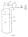
- FIG. 2 shows an example of a partial solution to the above-mentioned drawback where the short vertical length of the liquid tube does not provide a sufficient level of pressure head to resist liquid fluid flow out of the liquid tube.
- this drawback may be present in horizontal tanks where the liquid tube has a much shorter height than in vertical tanks.
- the system of FIG. 2 is described in U.S. Pat. No. 5,421,161, which is incorporated herein by reference in its entirety.
- Horizontal pressure vessels are commonly used as fuel tanks on vehicles where the tank is mounted to the underside of the vehicle and the tank stores LNG that fuels the vehicle's engine.
- a vaporizer 230 is positioned along the withdrawal line 225 for vaporizing the fluid before it is delivered to the gas use device 150 .
- a control valve 260 is also positioned along the withdrawal line 225 .
- Cryogenic liquid 210 or vapor 215 is provided to the withdrawal line 225 while the control valve 260 is open. When the control valve 260 is closed, cryogenic liquid or vapor may return to the pressure vessel through orifice 255 .
- the withdrawal line 225 includes a relief valve 250 located downstream of the liquid tube 220 and upstream of the vaporizer 230 . Since there is no longer a return flow path from the withdrawal line to the tank, the withdrawal line 225 also includes an orifice 255 that bypasses the relief valve 250 .
- the relief valve 250 and orifice 255 collectively enable the system of FIG. 2 to work efficiently, as will be described in detail further below.
- the system of FIG. 2 works similar to the system described with respect to FIG. 1 .
- the relief valve 250 is configured to provide a predetermined level of back pressure in the liquid tube 220 .
- any device configured to provide a level of back pressure may be used, such as, for example, a weight or an automatic valve. (Accordingly, this disclosure is not limited to the use of a pressure relief valve.)
- the pressure relief valve 250 thus ensures that the liquid tube 220 has a back pressure that is greater than the back pressure in the economizer circuit 235 .
- the regulator 245 allows return flow from the withdrawal line 225 to the tank 205 when the pressure in the withdrawal line 225 exceeds its set point. This happens when the relatively small return flow rate through the orifice 255 is exceeded by the rate of vapor generation in the vaporizer (i.e. heat exchanger) 230 and withdrawal line 225 . This can happen when a large liquid flow to the use device is interrupted by the control valve 260 .
- the control valve 260 may comprise a throttle valve and a throttle. Cryogenic fluid remaining in the withdrawal line 225 during transient throttle conditions such as when the throttle closes or reduces during coasting of the vehicle will cause there to be more liquid in the vaporizer 230 and withdrawal line 225 than the engine demands.
- the pressure within the withdrawal line 225 and vaporizer 230 may rise, such as due to vaporization of liquid remaining in the line or due to transient throttle conditions. If the rate of pressure rise exceeds the rate of pressure decay provided by return flow through the orifice 255 , the line pressure will rise until it reaches the regulator set pressure, causing it to open, providing a large return flow path to the tank 205 through the regulator 245 . Since the tank 205 normally operates at the set pressure of the regulator 245 , the regulator will normally cycle open with every power reduction of the vehicle providing a constantly large and fast path for return flow.
- the regulator 245 setting determines the tank's normal operating pressure and is set to match the minimum pressure desired by the engine.
- the fuel is normally delivered at or above this minimum pressure to ensure normal engine operation.
- the tank is fuelled at a pressure below its normal operating pressure, it will cause operational problems. For example, if a tank with a regulator 245 setting of 100 psig is fuelled with fuel at 70 psig, the vehicle will initially run poorly because its pressure is 30 psi below the pressure required for normal operation. The vehicle's acceleration will be sluggish; it may run quite roughly and may not be able to develop full power since the tank's pressure is insufficient to deliver the fuel demand of the engine.
- the check valve permits a free flow of vapor and liquid from the withdrawal line 225 to the pressure vessel 205 , the backflow of heat to the pressure vessel is always available to assist the pressure vessel 205 in maintaining or building pressure, independent of the regulator 245 setting. This allows tanks (i.e. pressure vessels) that are mis-fuelled with low pressure fuel to quickly rebuild pressure and resume normal operation.
- the cryogenic liquid 210 flows from the pressure vessel 205 ( FIG. 3 ) to the use device 150 ( FIG. 3 )
- the liquid enters the lumen 505 from the liquid tube 220 through port 455 .
- the liquid passes the retainer 540 and pushes the ball 535 toward and into the seat 545 of the moveable check valve 520 blocking passage 525 .
- the spring 515 force now acts against the pressure of the liquid through the closed check valve 520 providing the necessary back pressure for the proper function of the regulator 245 .
- Once the pressure of the liquid acting against the check valve 520 exceeds the spring force it moves the moveable check valve 520 against the spring 515 towards the retainer 510 . In this manner, the movable check valve 520 moves out of engagement with the seat 550 so that it no longer blocks flow from the liquid tube 220 , allowing liquid to flow through the outlet holes 465 into the withdrawal line 225 .
- the moveable check valve 520 moves back to the default state shown in FIG. 5 such that the moveable check valve 520 engages the seat 550 .
- the fluid from the withdrawal line 225 flows through openings 460 & 525 and pushes the ball 535 off the seat 545 to provide an opening for fluid to flow freely around the ball.
- the retainer 540 keeps the ball 535 in place and allows for fluid flow around the ball 535 , through the lumen 505 , out of first port 455 , into the liquid tube 220 ( FIG. 3 ), and into the pressure vessel 205 .
- the specifications of the mechanism shown in FIG. 5 may vary. Below are some exemplary mechanism specifications.
- the mechanism shown in FIG. 5 is configured such that the force exerted by the spring 515 on the moveable check valve 520 is a set value equal to 1 to 3 psi (approximately 6.9 to 20.7 kPa).
- the force exerted by the spring 515 is variable and may be changed to suit various requirements.
Landscapes
- Engineering & Computer Science (AREA)
- Mechanical Engineering (AREA)
- General Engineering & Computer Science (AREA)
- Filling Or Discharging Of Gas Storage Vessels (AREA)
Abstract
Description
Claims (11)
Priority Applications (1)
| Application Number | Priority Date | Filing Date | Title |
|---|---|---|---|
| US13/413,104 US9581295B2 (en) | 2012-03-06 | 2012-03-06 | Economizer biasing valve for cryogenic fluids |
Applications Claiming Priority (1)
| Application Number | Priority Date | Filing Date | Title |
|---|---|---|---|
| US13/413,104 US9581295B2 (en) | 2012-03-06 | 2012-03-06 | Economizer biasing valve for cryogenic fluids |
Publications (2)
| Publication Number | Publication Date |
|---|---|
| US20130232997A1 US20130232997A1 (en) | 2013-09-12 |
| US9581295B2 true US9581295B2 (en) | 2017-02-28 |
Family
ID=49112823
Family Applications (1)
| Application Number | Title | Priority Date | Filing Date |
|---|---|---|---|
| US13/413,104 Active 2033-05-28 US9581295B2 (en) | 2012-03-06 | 2012-03-06 | Economizer biasing valve for cryogenic fluids |
Country Status (1)
| Country | Link |
|---|---|
| US (1) | US9581295B2 (en) |
Families Citing this family (7)
| Publication number | Priority date | Publication date | Assignee | Title |
|---|---|---|---|---|
| GB2499815B (en) * | 2012-02-29 | 2014-05-28 | Siemens Plc | Over-pressure limiting arrangement for a cryogen vessel |
| US9746132B2 (en) | 2012-09-19 | 2017-08-29 | Chart Inc. | Self-saturating liquefied natural gas delivery system utilizing hydraulic pressure |
| KR101497420B1 (en) * | 2013-07-05 | 2015-03-03 | 삼성중공업 주식회사 | LNG transportation Apparatus for reducing Boil-Off Gas |
| CA2831762C (en) * | 2013-10-31 | 2015-01-20 | Westport Power Inc. | System and method for delivering a fluid stored in liquefied form to an end user in gaseous form |
| FR3015651A1 (en) * | 2013-12-20 | 2015-06-26 | Air Liquide | METHOD AND APPARATUS FOR HEATING A FLUID |
| CN105318939A (en) * | 2014-08-05 | 2016-02-10 | 重庆巨创计量设备股份有限公司 | LNG dispenser calibrating device |
| WO2018200725A1 (en) * | 2017-04-25 | 2018-11-01 | Chart Inc. | Pressure building cryogenic fluid delivery system |
Citations (4)
| Publication number | Priority date | Publication date | Assignee | Title |
|---|---|---|---|---|
| US2634947A (en) * | 1948-01-06 | 1953-04-14 | Lawrence H Gardner | Flow control valve |
| US5421161A (en) | 1993-09-27 | 1995-06-06 | Minnesota Valley Engineering, Inc. | Storage system for cryogenic fluids |
| US7413585B2 (en) * | 2005-04-14 | 2008-08-19 | Gm Global Technology Operations, Inc. | Closed pressure-keeping system for liquid hydrogen storage |
| US8132558B2 (en) * | 2009-12-01 | 2012-03-13 | Stanadyne Corporation | Common rail fuel pump with combined discharge and overpressure relief valves |
-
2012
- 2012-03-06 US US13/413,104 patent/US9581295B2/en active Active
Patent Citations (4)
| Publication number | Priority date | Publication date | Assignee | Title |
|---|---|---|---|---|
| US2634947A (en) * | 1948-01-06 | 1953-04-14 | Lawrence H Gardner | Flow control valve |
| US5421161A (en) | 1993-09-27 | 1995-06-06 | Minnesota Valley Engineering, Inc. | Storage system for cryogenic fluids |
| US7413585B2 (en) * | 2005-04-14 | 2008-08-19 | Gm Global Technology Operations, Inc. | Closed pressure-keeping system for liquid hydrogen storage |
| US8132558B2 (en) * | 2009-12-01 | 2012-03-13 | Stanadyne Corporation | Common rail fuel pump with combined discharge and overpressure relief valves |
Also Published As
| Publication number | Publication date |
|---|---|
| US20130232997A1 (en) | 2013-09-12 |
Similar Documents
| Publication | Publication Date | Title |
|---|---|---|
| US9581295B2 (en) | Economizer biasing valve for cryogenic fluids | |
| EP2989370B1 (en) | Liquid natural gas cooling on the fly | |
| CN101622491B (en) | Storage tank for a cryogenic fluid with a partitioned cryogen space | |
| CA2132946C (en) | Improved storage system for cryogenic fluids | |
| CA2617999C (en) | Tank manifold assembly | |
| US8459241B2 (en) | Liquefied natural gas system for a natural gas vehicle | |
| EP3396228B1 (en) | Pressure building cryogenic fluid delivery system | |
| EP1316754A1 (en) | High flow pressurized cryogenic fluid dispensing system | |
| US7114342B2 (en) | Pressure management system for liquefied natural gas vehicle fuel tanks | |
| US9746132B2 (en) | Self-saturating liquefied natural gas delivery system utilizing hydraulic pressure | |
| US11118736B2 (en) | Space conserving integrated cryogenic fluid delivery system | |
| WO2005070103A2 (en) | Pressure control device for cryogenic liquid vessel | |
| US20160356423A1 (en) | Non-venting transfer system and method | |
| KR101747041B1 (en) | LNG fuel supply system of LNG vehicle | |
| CN105518376A (en) | Low-loss cryogenic fluid supply system and method | |
| JP2006052814A (en) | Gas supply system |
Legal Events
| Date | Code | Title | Description |
|---|---|---|---|
| AS | Assignment |
Owner name: CHART INC., GEORGIA Free format text: ASSIGNMENT OF ASSIGNORS INTEREST;ASSIGNOR:GUSTAFSON, ERIK;REEL/FRAME:029119/0296 Effective date: 20120607 |
|
| AS | Assignment |
Owner name: JPMORGAN CHASE BANK, N.A., AS ADMINISTRATIVE AGENT Free format text: SECURITY INTEREST;ASSIGNOR:CHART INC.;REEL/FRAME:034812/0256 Effective date: 20141029 |
|
| STCF | Information on status: patent grant |
Free format text: PATENTED CASE |
|
| MAFP | Maintenance fee payment |
Free format text: PAYMENT OF MAINTENANCE FEE, 4TH YEAR, LARGE ENTITY (ORIGINAL EVENT CODE: M1551); ENTITY STATUS OF PATENT OWNER: LARGE ENTITY Year of fee payment: 4 |
|
| AS | Assignment |
Owner name: U.S. BANK TRUST COMPANY, NATIONAL ASSOCIATION, AS THE NOTES COLLATERAL AGENT, TEXAS Free format text: PATENT CONFIRMATORY GRANT;ASSIGNOR:CHART INC.;REEL/FRAME:062793/0692 Effective date: 20221222 |