US9595969B2 - Reciprocal quantum logic comparator for qubit readout - Google Patents
Reciprocal quantum logic comparator for qubit readout Download PDFInfo
- Publication number
- US9595969B2 US9595969B2 US15/008,022 US201615008022A US9595969B2 US 9595969 B2 US9595969 B2 US 9595969B2 US 201615008022 A US201615008022 A US 201615008022A US 9595969 B2 US9595969 B2 US 9595969B2
- Authority
- US
- United States
- Prior art keywords
- josephson junction
- qubit
- quantum state
- bias current
- pulse
- Prior art date
- Legal status (The legal status is an assumption and is not a legal conclusion. Google has not performed a legal analysis and makes no representation as to the accuracy of the status listed.)
- Active
Links
- 239000002096 quantum dot Substances 0.000 title claims abstract description 143
- 230000004044 response Effects 0.000 claims abstract description 49
- 238000000034 method Methods 0.000 claims description 16
- 230000008878 coupling Effects 0.000 claims description 11
- 238000010168 coupling process Methods 0.000 claims description 11
- 238000005859 coupling reaction Methods 0.000 claims description 11
- 230000001939 inductive effect Effects 0.000 claims description 10
- 230000007423 decrease Effects 0.000 claims description 4
- 230000008859 change Effects 0.000 claims description 3
- 230000001360 synchronised effect Effects 0.000 claims 1
- 230000000644 propagated effect Effects 0.000 description 8
- 238000010586 diagram Methods 0.000 description 5
- 238000002955 isolation Methods 0.000 description 3
- 230000000694 effects Effects 0.000 description 2
- 238000005516 engineering process Methods 0.000 description 2
- 230000004075 alteration Effects 0.000 description 1
- 230000008901 benefit Effects 0.000 description 1
- 230000015556 catabolic process Effects 0.000 description 1
- 238000012937 correction Methods 0.000 description 1
- 238000006731 degradation reaction Methods 0.000 description 1
- 230000004907 flux Effects 0.000 description 1
- 238000010438 heat treatment Methods 0.000 description 1
- 230000003993 interaction Effects 0.000 description 1
- 238000004519 manufacturing process Methods 0.000 description 1
- 238000012986 modification Methods 0.000 description 1
- 230000004048 modification Effects 0.000 description 1
- 238000012545 processing Methods 0.000 description 1
- 230000001902 propagating effect Effects 0.000 description 1
- 230000035945 sensitivity Effects 0.000 description 1
Images


Classifications
-
- H—ELECTRICITY
- H03—ELECTRONIC CIRCUITRY
- H03K—PULSE TECHNIQUE
- H03K19/00—Logic circuits, i.e. having at least two inputs acting on one output; Inverting circuits
- H03K19/02—Logic circuits, i.e. having at least two inputs acting on one output; Inverting circuits using specified components
- H03K19/195—Logic circuits, i.e. having at least two inputs acting on one output; Inverting circuits using specified components using superconductive devices
-
- G—PHYSICS
- G06—COMPUTING; CALCULATING OR COUNTING
- G06N—COMPUTING ARRANGEMENTS BASED ON SPECIFIC COMPUTATIONAL MODELS
- G06N10/00—Quantum computing, i.e. information processing based on quantum-mechanical phenomena
-
- G—PHYSICS
- G06—COMPUTING; CALCULATING OR COUNTING
- G06N—COMPUTING ARRANGEMENTS BASED ON SPECIFIC COMPUTATIONAL MODELS
- G06N10/00—Quantum computing, i.e. information processing based on quantum-mechanical phenomena
- G06N10/40—Physical realisations or architectures of quantum processors or components for manipulating qubits, e.g. qubit coupling or qubit control
-
- G06N99/002—
-
- G—PHYSICS
- G11—INFORMATION STORAGE
- G11C—STATIC STORES
- G11C11/00—Digital stores characterised by the use of particular electric or magnetic storage elements; Storage elements therefor
- G11C11/21—Digital stores characterised by the use of particular electric or magnetic storage elements; Storage elements therefor using electric elements
- G11C11/44—Digital stores characterised by the use of particular electric or magnetic storage elements; Storage elements therefor using electric elements using super-conductive elements, e.g. cryotron
-
- H01L39/223—
-
- H—ELECTRICITY
- H03—ELECTRONIC CIRCUITRY
- H03K—PULSE TECHNIQUE
- H03K3/00—Circuits for generating electric pulses; Monostable, bistable or multistable circuits
- H03K3/02—Generators characterised by the type of circuit or by the means used for producing pulses
- H03K3/38—Generators characterised by the type of circuit or by the means used for producing pulses by the use, as active elements, of superconductive devices
-
- H—ELECTRICITY
- H10—SEMICONDUCTOR DEVICES; ELECTRIC SOLID-STATE DEVICES NOT OTHERWISE PROVIDED FOR
- H10N—ELECTRIC SOLID-STATE DEVICES NOT OTHERWISE PROVIDED FOR
- H10N60/00—Superconducting devices
- H10N60/10—Junction-based devices
- H10N60/12—Josephson-effect devices
Definitions
- the present invention relates generally to quantum and classical digital superconducting circuits, and specifically to a reciprocal quantum logic (RQL) comparator for qubit readout.
- RQL reciprocal quantum logic
- Superconducting digital technology has provided computing and/or communications resources that benefit from unprecedented high speed, low power dissipation, and low operating temperature.
- a typical goal in the implementation of a superconducting circuit is very high-speed manipulation of data (e.g., tens of Gigahertz) in a manner that is very power efficient and minimizes losses through temperature.
- Superconducting technology can implement qubits to store quantum information.
- a qubit is a phase qubit, which can be configured as an LC resonator, such as formed from an inductor shunting a Josephson junction.
- a control circuit can be employed to write to the phase qubit and a readout circuit can be employed to read a quantum state from the phase qubit.
- One example includes a readout system configured to read a quantum state of a qubit.
- the system includes an input stage on which a read pulse is provided and an output stage.
- the system also includes a comparator circuit coupled to the qubit and configured to provide an output pulse on the output stage in response to the read pulse to indicate a first quantum state of the qubit, and to not provide the output pulse on the output stage in response to the read pulse to indicate a second quantum state of the qubit.
- Another example includes a method for reading a quantum state of a phase qubit.
- the method includes providing a bias current in a first direction in response to a first quantum state of the phase qubit and in a second direction in response to a second quantum state of the phase qubit and applying a read pulse on an input stage.
- the method also includes providing an output pulse from a comparator circuit to an output stage in response to the read pulse based on the bias current being provided in the first direction.
- the method further includes not providing the output pulse from the comparator circuit to the output stage in response to the read pulse based on the bias current being provided in the second direction.
- RQL reciprocal quantum logic
- the system includes an input stage on which a read pulse is provided in response to an RQL clock signal.
- the system also includes an output stage configured to propagate an output pulse in response to the RQL clock signal.
- the system further includes an RQL comparator coupled to the qubit and configured to provide an output pulse on the output stage based on triggering a first Josephson junction in response to the read pulse and the RQL clock signal to indicate a first quantum state of the qubit, and to not provide the output pulse on the output stage based on triggering a second Josephson junction in response to the read pulse and the RQL clock signal to indicate a second quantum state of the qubit.
- FIG. 1 illustrates an example of an RQL readout system.
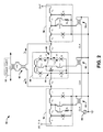
- FIG. 2 illustrates an example of an RQL readout circuit.
- FIG. 3 illustrates an example of a timing diagram
- FIG. 4 illustrates an example of a method for reading a quantum state of a phase qubit.
- the present invention relates generally to quantum and classical digital superconducting circuits, and specifically to a reciprocal quantum logic (RQL) comparator for qubit readout.
- An RQL readout system can include an input stage on which a read pulse is provided.
- the input stage can include at least one input Josephson junction on which the read pulse can propagate.
- the read pulse can be provided, such as from an external RQL circuit, to determine a quantum state of a phase qubit.
- the RQL readout system can also include an output stage configured to propagate an output pulse in a first quantum state of the phase qubit in response to the read pulse. If the phase qubit is in the second quantum state, the output pulse is not provided on the output stage in response to the read pulse.
- the RQL readout system also includes an RQL comparator comprising a first Josephson junction and a second Josephson junction that are coupled to the phase qubit.
- the quantum state of the phase qubit can set a relative threshold associated with each of the first and second Josephson junctions.
- the phase qubit can be inductively coupled to the RQL comparator to provide a bias current flow in either a first direction or a second direction through the Josephson junctions depending on the quantum state of the phase qubit.
- one of the first and second Josephson junctions can trigger in response to the read pulse based on the bias current being either added to or subtracted from the read pulse based on the direction of current flow of the bias current through the first and second Josephson junctions, respectively, to either provide or not provide the output pulse on the output stage.
- the RQL readout system also includes an RQL clock that provides RQL clock signal to each of the input stage, the output stage, and the RQL comparator. Because the phase qubit can be inductively coupled to the RQL comparator, the phase qubit can be effectively isolated from the RQL clock and the associated shunting resistors. As a result, the phase qubit is decoupled from potential noise sources to substantially prevent degradation of coherence time of the phase qubit.
- the RQL clock signal can affect the thresholds of the Josephson junctions in the input stage, the output stage, and the RQL comparator to facilitate triggering of the Josephson junctions, such that the read pulse can be provided at a first cycle (e.g., positive cycle) of the RQL clock signal. During a second cycle (e.g., negative cycle) of the RQL clock signal, a negative pulse can be provided to reset the respective Josephson junctions, thus allowing subsequent readout of the quantum state of the phase qubit.
- a first cycle
- FIG. 1 illustrates an example of an RQL readout system 10 .
- the RQL readout system 10 can be implemented in a variety of quantum and classical computing environments to read a quantum state from a superconducting qubit 12 .
- at least a portion of the RQL readout system 10 can be implemented on an integrated circuit (IC) in a superconducting environment.
- the qubit 12 is configured as a phase qubit.
- the phase qubit 12 can be arranged as a Josephson junction embedded in a superconducting loop (e.g., an inductor).
- the “one” and “zero” quantum states of the phase qubit 12 can differ by the presence or absence of one flux quantum in the inductor of the phase qubit 12 (e.g., having a current difference of approximately 3 ⁇ A or less).
- the RQL readout system 10 also includes an input stage 14 , an output stage 16 , and an RQL comparator 18 .
- the input stage 14 is configured to propagate a read pulse RD_PLS that is provided to read the quantum state of the phase qubit 12 , such as during a readout operation.
- the read pulse RD_PLS can be generated from an external circuit, such as the input stage 14 can include at least one input Josephson junction that can sequentially trigger to propagate the read pulse RD_PLS.
- the output stage 16 is configured to propagate an output pulse OUT that is generated in response to the read pulse RD_PLS in a first quantum state of the phase qubit 12 .
- the output stage 16 can include at least one output Josephson junction that can sequentially trigger to propagate the output pulse OUT to indicate that the phase qubit 12 is in the first quantum state. Conversely, if the phase qubit 12 is in the second quantum state, no output pulse OUT is generated. Therefore, the output pulse OUT is not propagated at the output stage 16 in response to the read pulse RD_PLS when the phase qubit 12 is in the second quantum state.
- the RQL comparator 18 is configured to determine the quantum state of the phase qubit 12 in response to the read pulse RD_PLS, and to generate the output pulse OUT if the phase qubit 12 is in the first quantum state. Therefore, the quantum state of the phase qubit 12 can be indicated to other quantum or classical circuits. For example, the output pulse OUT can be implemented for quantum error correction or a variety of other quantum or classical processing applications.
- the phase qubit 12 is demonstrated as coupled to the RQL comparator 18 symmetrically, such that a bias current I Q can flow through the RQL comparator 18 . The direction of the flow of the bias current I Q can be based on the quantum state of the phase qubit 12 .
- the phase qubit 12 can be inductively coupled to the RQL comparator 18 , such that the bias current I Q can be magnetically induced to flow through the RQL comparator 18 .
- inductive coupling refers to magnetic coupling between respective inductors, such that a current flow through one inductor induces a current flow through the other inductor based on a magnetic field through a common core of the respective inductors.
- the RQL comparator 18 includes Josephson junctions 20 that can be arranged symmetrically with respect to the phase qubit 12 .
- the RQL comparator 18 can include a first of the Josephson junctions 20 and a second of the Josephson junctions 20 through which the portions of the bias current I Q flow and which are each coupled to the output stage 16 .
- the direction of the bias current I Q in the current loop can thus disproportionally affect a threshold of each of the first and second Josephson junctions 20 to selectively trigger one of the first and second Josephson junctions 20 in response to the read pulse RD_PLS.
- the first Josephson junction can trigger to provide the output pulse OUT.
- the bias current I Q flowing through the first of the Josephson junctions 20 can be added to the read pulse RD_PLS to exceed the threshold of the first of the Josephson junctions 20 , thus triggering the first of the Josephson junctions 20 to generate the output pulse OUT.
- the second Josephson junction can trigger to prevent the output pulse OUT from propagating on the output stage 16 .
- the bias current I Q flowing through the first of the Josephson junctions 20 can be subtracted from the read pulse RD_PLS to not reach the threshold of the first of the Josephson junctions 20 to not trigger the first of the Josephson junctions 20 , but instead triggering the second of the Josephson junctions 20 , resulting in no generation of the output pulse OUT.
- the RQL readout system 10 also includes an RQL clock 22 that is configured to generate an RQL clock signal CLK.
- the RQL clock signal CLK can be a four phase (e.g., quadrature) clock signal, such as having a very high frequency (e.g., tens of gigahertz).
- the RQL clock signal CLK is demonstrated as being provided to the input stage 14 , the output stage 16 , and the RQL comparator 18 .
- the read pulse RD_PLS when combined with the RQL clock signal CLK, can exceed the thresholds of at least a portion of the input Josephson junctions in the input stage, the output Josephson junctions in the output stage, and the Josephson junctions 20 in the RQL comparator 18 to facilitate triggering of the respective Josephson junctions.
- the read pulse can be provided at a first cycle (e.g., positive cycle) of the RQL clock signal CLK, and during a second cycle (e.g., negative cycle) of the RQL clock signal CLK, a negative pulse can be provided to reset the respective Josephson junctions.
- the RQL clock signal CLK can be provided to RQL comparator 18 in a common-mode connection, such that the Josephson junctions 20 are arranged symmetrically with respect to the RQL clock signal CLK. Therefore, based on the balanced connection of the RQL clock signal CLK in the input stage 14 , the output stage 16 , and the RQL comparator 18 , the RQL clock signal CLK and associated shunt resistors do not imbalance the bias current I Q . Additionally, because of the inductive coupling of the phase qubit 12 to the RQL comparator 18 , the RQL clock signal CLK is effectively isolated from the phase qubit 12 .
- the RQL readout system 10 therefore provides a manner for reading the quantum state of the phase qubit 12 in a very rapid manner with substantially mitigated decoherence. Because the RQL readout system 10 implements RQL-based quantum logic, the RQL readout system 10 can be configured to provide readout of the quantum state of the phase qubit 12 at very rapid data rates (e.g., reading the quantum state in less than one nanosecond) with substantially minimal losses and generated heat (e.g., operating at temperatures of approximately 20 mK without causing local heating).
- the RQL readout system 10 can distinguish current amplitude changes of, for example, less than approximately 3 ⁇ A, and can thus achieve a very high sensitivity. Furthermore, based on the isolation of the phase qubit 12 from the RQL clock signal CLK and based on the balanced arrangement of the RQL clock signal CLK, the RQL readout system 10 can substantially mitigate decoherence of the quantum state of the phase qubit 12 .
- the RQL readout system 10 is demonstrated simplistically, such that the RQL readout system 10 can include one or more circuit devices that interconnect and/or are included in the components of the RQL readout system 10 .
- the term “coupled” can refer to electrical coupling through one or more circuit devices (e.g., an inductor) in the associated quantum circuit, such that current and/or current pulses can flow between coupled components through one or more inductors or other devices. Therefore, coupling between devices in the RQL readout system 10 can include coupling through inductors and/or other circuit devices.
- FIG. 2 illustrates an example of an RQL readout circuit 50 .
- the RQL readout circuit 50 can correspond to the RQL readout system 10 in the example of FIG. 1 . Therefore, the RQL readout circuit 50 can be implemented in a variety of quantum and classical computing environments to read a quantum state from a phase qubit 52 . As an example, at least a portion of the RQL readout circuit 50 can be implemented on an IC in a superconducting environment (e.g., at a very low temperature).
- the RQL readout circuit 50 also includes an input stage 54 , an output stage 56 , and an RQL comparator 58 .
- the input stage 54 is configured to propagate a read pulse RD_PLS that is provided to read the quantum state of the phase qubit 52 , such as during a readout operation.
- the read pulse RD_PLS can be generated from an external circuit, such as the input stage 54 can include at least one input Josephson junction that can sequentially trigger to propagate the read pulse RD_PLS.
- the input stage 54 includes a set of inductors through which the read pulse RD_PLS is provided. In the example of FIG.
- the input stage 54 includes a first inductor L 1 , a second inductor L 2 , a third inductor L 3 , and a fourth inductor L 4 .
- the input stage 54 also includes a first Josephson junction J 1 that is coupled to the first and second inductors L 1 and L 2 and to a low-voltage rail (e.g., ground), and includes a second Josephson junction J 2 that is coupled to the third and fourth inductors L 3 and L 4 and to the low-voltage rail.
- the first and second Josephson junctions J 1 and J 2 are configured to sequentially trigger to propagate the read pulse RD_PLS along the input stage 54 via the second, third, and fourth inductors L 2 , L 3 , and L 4 .
- the RQL readout circuit 50 includes an RQL clock 60 that is configured to generate the RQL clock signal CLK that is provided to the input stage 54 between the second and third inductors L 2 and L 3 via an inductive coupling 61 (e.g., a transformer) and an inductor L C1 .
- the RQL clock signal CLK thus facilitates triggering of the first and second Josephson junctions J 1 and J 2 .
- the read pulse RD_PLS can be provided substantially concurrently with a positive cycle of the RQL clock signal CLK, such that the first and second Josephson junctions J 1 and J 2 can have sufficient current to trigger in response to the read pulse RD_PLS.
- the RQL clock signal CLK is shunted to ground via an inductor L C2 and a resistor R 1 .
- the resistor R 1 is also provided as a common shunting resistor for the first and second Josephson junctions J 1 and J 2 .
- the inductor L 3 can provide additional inductive isolation of the resistor R 1 with respect to the phase qubit 52 , such as to further mitigate the effects of resistor noise on the qubit coherence time of the phase qubit 52 .
- the RQL comparator 58 is configured to determine the quantum state of the phase qubit 52 in response to the read pulse RD_PLS, and to generate the output pulse OUT if the phase qubit 52 is in the first quantum state.
- the inductor L PQ1 of the phase qubit 52 is demonstrated as inductively coupled to an inductor L PQ2 to induce the current I Q based on the quantum state of the phase qubit 52 through the inductor L PQ2 and through a transformer 62 that is arranged as an inductive common-mode choke (e.g., to substantially mitigate an inductance acting upon the current I Q ).
- the current I Q is demonstrated as currents I Q1 and I Q2 flowing in opposite directions.
- the current I Q1 and I Q2 correspond to the current I Q flowing in opposite directions depending on the quantum state of the phase qubit 52 .
- the current I Q1 can correspond to the current I Q flowing in a first direction based on the phase qubit 52 having a first quantum state
- the current I Q2 can correspond to the current I Q flowing in a second direction based on the phase qubit 54 having a second quantum state. Therefore, the currents I Q1 and I Q2 are substantially equal in magnitude and direction based on the quantum state of the phase qubit 52 .
- the phase qubit 52 is inductively coupled to the RQL comparator 58 via the inductor L PQ2 , the transformer 62 , an inductor L I1 that is coupled to the input stage 54 , and an inductor L O1 that is coupled to the output stage 54 .
- the RQL comparator 58 includes Josephson junctions J 3 and J 4 that are each coupled to the inductor L I1 at a node 64 , and Josephson junctions J 5 and J 6 that are each coupled to the inductor L O1 at a node 66 .
- the Josephson junctions J 4 and J 5 are coupled via inductors L RQ1 and L RQ2 , and the Josephson junctions J 3 and J 6 are coupled to ground.
- the RQL clock signal CLK is provided in a common-mode manner between the inductors L RQ1 and L RQ2 via an inductive coupling 68 (e.g., a transformer) and a pair of inductors L C3 and L C4 , with a shunt resistor R 2 interconnecting the inductors L C3 and L C4 to ground. Therefore, the phase qubit 52 is symmetrically coupled to the RQL comparator 58 , and the RQL comparator 58 is symmetric with respect to the circuit components therein. Similar to as described previously, the RQL clock signal CLK facilitates triggering of the Josephson junctions therein.
- the read pulse RD_PLS can be provided substantially concurrently with a positive cycle of the RQL clock signal CLK, such that the Josephson junction J 3 can propagate the read pulse RD_PLS to the Josephson junctions J 5 and J 6 , and one of the Josephson junctions J 5 and J 6 can have sufficient current to trigger in response to the read pulse RD_PLS.
- the resistor R 2 is symmetrically arranged with respect to the phase qubit 52 as a common shunt resistor with respect to the Josephson junctions J 3 , J 4 , J 5 , and J 6 , as opposed to typical superconducting circuit applications in which shunt resistors are provided in parallel with each respective Josephson junction of the given circuit. Accordingly, the symmetrical common shunt arrangement of the resistor R 2 substantially mitigates the presence of noise that could degrade a coherence time of the phase qubit 52 .
- the direction of the flow of the bias current I Q can be based on the quantum state of the phase qubit 52 , and thus flows through the inductor L O1 and into the node 66 as the current I Q1 , or flows out from the node 66 and through inductor L O1 as the current I Q2 .
- the current I Q1 is demonstrated as splitting at the node 66 , with a first portion of the current I Q1 (demonstrated as a current I J51 ) flowing through the Josephson junction J 5 to the inductor L RQ2 and a second portion of the current I Q1 (demonstrated as a current I J61 ) flowing through the Josephson junction J 6 to ground.
- the current I Q2 is demonstrated as joining at the node 66 , with a first portion of the current I Q2 (demonstrated as a current I J52 ) flowing through the Josephson junction J 5 to the node 66 and a second portion of the current I Q2 (demonstrated as a current I J62 ) flowing through the Josephson junction J 6 to the node 66 from ground. Therefore, currents I J51 and I J61 correspond to the current I Q1 , and thus the first quantum state of the phase qubit 52 , and the currents I J52 and I J62 correspond to the current I Q2 , and thus the second quantum state of the phase qubit 52 . Accordingly, the currents I J51 and I J61 and the currents I J52 and I J62 change the relative threshold of the Josephson junctions J 5 and J 6 with respect to the read pulse RD_PLS.
- the read pulse RD_PLS propagates through the input stage 54 (e.g., through the inductors L 1 , L 2 , L 3 , and L 4 via the Josephson junctions J 1 and J 2 ) and through the inductor L I1 to trigger the Josephson junction J 3 .
- the read pulse RD_PLS thus gets propagated through inductors L RQ1 and L RQ2 to the Josephson junctions J 5 and J 6 .
- the bias current I Q is either added to or subtracted from the read pulse RD_PLS with respect to Josephson junctions J 5 and J 6 based on the quantum state of the phase qubit 52 .
- the current I Q1 flows into the node 66 , and thus the current I J51 flows from the node 66 through the Josephson junction J 5 and the current I J61 flows from the node 66 through the Josephson junction J 6 .
- the current I J51 flows oppositely with respect to the read pulse RD_PLS propagated from the Josephson junction J 3 and through the inductors L RQ1 and L RQ2 , the current I J51 is subtracted from the read pulse RD_PLS (e.g., increases the threshold of the Josephson junction J 5 ).
- Josephson junction J 5 does not trigger in the first quantum state of the phase qubit 52 .
- the current I J61 flows in the same direction as the read pulse RD_PLS propagated from the Josephson junction J 3 and through the inductors L RQ1 and L RQ2 , the current I J61 is added to the read pulse RD_PLS (e.g., decreases the threshold of the Josephson junction J 6 ).
- Josephson junction J 6 triggers in the first quantum state of the phase qubit 52 .
- the current I Q2 flows from the node 66 , and thus the current I J52 flows into the node 66 through the Josephson junction J 5 and the current I J62 flows into the node 66 through the Josephson junction J 6 .
- the current I J52 flows in the same direction as the read pulse RD_PLS propagated from the Josephson junction J 3 and through the inductors L RQ1 and L RQ2 .
- the current J J52 is added to the read pulse RD_PLS (e.g., decreases the threshold of the Josephson junction J 5 ).
- Josephson junction J 5 triggers in the second quantum state of the phase qubit 52 .
- Josephson junction J 6 does not trigger in the second quantum state of the phase qubit 52 .
- the output stage 56 is configured to propagate the output pulse OUT that is generated in response to the triggering of the Josephson junction J 6 , and thus in the first quantum state of the phase qubit 52 .
- the output stage 56 is demonstrated in the example of FIG. 2 as being arranged substantially similar (e.g., symmetrical) with respect to the input stage 54 .
- the output stage 56 includes a set of inductors through which the output pulse OUT propagates from the Josephson junction J 6 and through the inductor L O1 .
- the output stage 56 includes a first inductor L 5 , a second inductor L 6 , a third inductor L 7 , and a fourth inductor L 8 .
- the output stage 56 also includes a first Josephson junction J 7 that is coupled to the third and fourth inductors L 7 and L 8 and to ground, and includes a second Josephson junction J 8 that is coupled to the first and second inductors L 5 and L 6 and to ground.
- the first and second Josephson junctions J 7 and J 8 are configured to sequentially trigger to propagate the output pulse OUT along the output stage 56 via the second, third, and fourth inductors L 6 , L 7 , and L 8 .
- the RQL clock signal CLK is provided to the output stage 56 between the second and third inductors L 6 and L 7 via an inductive coupling 70 (e.g., a transformer) and an inductor L C5 , and is shunted to ground via an inductor L C6 and a resistor R 3 .
- the resistor R 3 is also provided as a common shunting resistor for the first and second Josephson junctions J 7 and J 8 .
- the inductor L 6 can provide additional inductive isolation of the resistor R 3 with respect to the phase qubit 52 , such as to further mitigate the effects of resistor noise on the qubit coherence time of the phase qubit 52 .
- the RQL clock signal CLK thus facilitates triggering of the first and second Josephson junctions J 7 and J 8 . Accordingly, in response to the triggering of the Josephson junction J 6 in response to the read pulse RD_PLS in the first quantum state of the phase qubit 52 , the output pulse OUT is provided at the output stage 56 to indicate the first quantum state of the phase qubit 52 . Conversely, in response to the triggering of the Josephson junction J 5 instead of the Josephson junction J 6 in response to the read pulse RD_PLS in the second quantum state of the phase qubit 52 , the output pulse OUT is not provided at the output stage 56 to indicate the second quantum state of the phase qubit 52 .
- the RQL readout circuit 50 is not limited to the example of FIG. 2 .
- the input stage 54 and the output stage 56 are not limited to as demonstrated in the example of FIG. 2 , but can include additional circuit components, such as one or more additional Josephson junctions and/or one or more additional inductors.
- the readout operation described herein is not limited to readout of a phase qubit 52 , but a variety of other qubits or circuit devices having logic or quantum states that are based on a current flow direction can be implemented in the RQL readout circuit 50 . Accordingly, the RQL readout circuit 50 can be configured in a variety of ways.
- FIG. 3 illustrates an example of a timing diagram 100 .
- the timing diagram 100 can correspond to the timing of the RQL readout circuit 50 . Therefore, reference is to be made to the example of FIG. 2 in the following description of the example of FIG. 3 .
- the timing diagram 100 demonstrates the current I Q1 , such that a positive magnitude of the current I Q1 demonstrates that the current I Q is provided as the current I Q1 in the first quantum state of the phase qubit 52 and a negative magnitude of the current I Q1 demonstrates that the current I Q is provided as the current I Q2 in the second quantum state of the phase qubit 52 .
- the timing diagram 100 also demonstrates the read pulse RD_PLS, the current I J51 , the current I J61 , and the output pulse OUT.
- the current I J51 is demonstrated as having a negative magnitude when the current I Q is provided as the current I Q2 in the second quantum state, and is demonstrated as having a positive magnitude to correspond to the current I J52 when the current I Q is provided as the current I Q1 in the first quantum state.
- the current I J61 is likewise demonstrated as having a negative magnitude when the current I Q is provided as the current I Q1 in the second quantum state, and is demonstrated as having a positive magnitude to correspond to the current I J62 when the current I Q is provided as the current I Q2 in the first quantum state.
- the current I Q1 is negative, such that the phase qubit 52 is in the second quantum state.
- the read pulse RD_PLS is provided at the input stage 54 , such as concurrently with a positive cycle of the RQL clock signal CLK.
- the current I J51 is negative at the time T 0 , and thus is added to the read pulse RD_PLS with respect to the Josephson junction J 5 .
- the current I J61 is also negative, and thus is subtracted from the read pulse RD_PLS with respect to the Josephson junction J 6 . Therefore, the Josephson junction J 5 triggers, and the Josephson junction J 6 does not trigger. As a result, the output pulse OUT is not generated and propagated along the output stage 56 .
- the output stage 56 indicates that the phase qubit 52 is in the second quantum state.
- the read pulse RD_PLS is provided as a negative pulse, such as substantially concurrently with a negative cycle of the RQL clock signal CLK, to reset the Josephson junctions of the RQL readout circuit 50 .
- the read pulse RD_PLS is provided again, resulting in an indication of the phase qubit 52 being in the second quantum state again, similar to as described previously.
- the read pulse RD_PLS is again provided as a negative pulse to reset the Josephson junctions of the RQL readout circuit 50 .
- the current I Q1 is positive, such that the phase qubit 52 is in the first quantum state.
- the read pulse RD_PLS is provided at the input stage 54 , the current I J51 is positive, and thus is subtracted from the read pulse RD_PLS with respect to the Josephson junction J 5 .
- the current I J61 is likewise positive, and thus is added to the read pulse RD_PLS with respect to the Josephson junction J 6 . Therefore, the Josephson junction J 5 does not trigger, and the Josephson junction J 6 triggers.
- the output pulse OUT is generated and propagates along the output stage 56 . Accordingly, the output stage 56 indicates that the phase qubit 52 is in the first quantum state.
- the read pulse RD_PLS is provided as a negative pulse to reset the Josephson junctions of the RQL readout circuit 50 .
- the read pulse RD_PLS is provided again, resulting in an indication of the phase qubit 52 being in the first quantum state again, similar to as described previously.
- the read pulse RD_PLS is again provided as a negative pulse to reset the Josephson junctions of the RQL readout circuit 50 .
- FIG. 4 a methodology in accordance with various aspects of the present invention will be better appreciated with reference to FIG. 4 . While, for purposes of simplicity of explanation, the methodology of FIG. 4 is shown and described as executing serially, it is to be understood and appreciated that the present invention is not limited by the illustrated order, as some aspects could, in accordance with the present invention, occur in different orders and/or concurrently with other aspects from that shown and described herein. Moreover, not all illustrated features may be required to implement a methodology in accordance with an aspect of the present invention.
- FIG. 4 illustrates an example of a method 150 for reading a quantum state of a phase qubit (e.g., the phase qubit 12 ).
- a bias current e.g., the bias current I Q
- a first Josephson junction e.g., the Josephson junction J 6
- a second Josephson junction e.g., the Josephson junction J 5
- a first direction e.g., the bias current I Q1
- a second direction e.g., the bias current I Q2
- a read pulse (e.g., the read pulse RD_PLS) is applied at a first cycle of an RQL clock signal (e.g., the RQL clock signal CLK), the read pulse being propagated on an input stage (e.g., the input stage 14 ) to the first and second Josephson junctions.
- an RQL clock signal e.g., the RQL clock signal CLK
- the phase qubit is determined to be in the first quantum state based on receiving an output pulse (e.g., the output pulse OUT) at an output stage (e.g., the output stage 16 ) in response to the read pulse the first Josephson junction triggering based on the bias current being provided in the first direction and the read pulse, or in the second quantum state based on not receiving output pulse at the output stage in response to the second Josephson junction triggering based on the bias current being provided in the second direction and the read pulse.
- an output pulse e.g., the output pulse OUT
- an output stage e.g., the output stage 16
Abstract
One aspect of the present invention includes a reciprocal quantum logic (RQL) readout system. The system includes an input stage on which a read pulse is provided and an output stage configured to propagate an output pulse. The system also includes an RQL comparator comprising a first Josephson junction and a second Josephson junction that are coupled to a qubit. A bias current switches between a first Josephson junction in a first quantum state of the qubit and a second Josephson junction in a second quantum state of the qubit. The first Josephson junction triggers to provide the output pulse on the output stage in the first quantum state in response to the read pulse and the second Josephson junction triggers to provide no output pulse on the output stage in the second quantum state in response to the read pulse.
Description
This application is a continuation of U.S. patent application Ser. No. 14/202,724, filed 10 Mar. 2014, which is incorporated herein in its entirety.
This invention was made with Government support under Contract No. W911NF-11-C-0069, Project No. 36545. The Government has certain rights in this invention.
The present invention relates generally to quantum and classical digital superconducting circuits, and specifically to a reciprocal quantum logic (RQL) comparator for qubit readout.
Superconducting digital technology has provided computing and/or communications resources that benefit from unprecedented high speed, low power dissipation, and low operating temperature. A typical goal in the implementation of a superconducting circuit is very high-speed manipulation of data (e.g., tens of Gigahertz) in a manner that is very power efficient and minimizes losses through temperature. Superconducting technology can implement qubits to store quantum information. One example of a qubit is a phase qubit, which can be configured as an LC resonator, such as formed from an inductor shunting a Josephson junction. A control circuit can be employed to write to the phase qubit and a readout circuit can be employed to read a quantum state from the phase qubit.
One example includes a readout system configured to read a quantum state of a qubit. The system includes an input stage on which a read pulse is provided and an output stage. The system also includes a comparator circuit coupled to the qubit and configured to provide an output pulse on the output stage in response to the read pulse to indicate a first quantum state of the qubit, and to not provide the output pulse on the output stage in response to the read pulse to indicate a second quantum state of the qubit.
Another example includes a method for reading a quantum state of a phase qubit. The method includes providing a bias current in a first direction in response to a first quantum state of the phase qubit and in a second direction in response to a second quantum state of the phase qubit and applying a read pulse on an input stage. The method also includes providing an output pulse from a comparator circuit to an output stage in response to the read pulse based on the bias current being provided in the first direction. The method further includes not providing the output pulse from the comparator circuit to the output stage in response to the read pulse based on the bias current being provided in the second direction.
Another example includes an reciprocal quantum logic (RQL) readout system configured to read a quantum state of a qubit. The system includes an input stage on which a read pulse is provided in response to an RQL clock signal. The system also includes an output stage configured to propagate an output pulse in response to the RQL clock signal. The system further includes an RQL comparator coupled to the qubit and configured to provide an output pulse on the output stage based on triggering a first Josephson junction in response to the read pulse and the RQL clock signal to indicate a first quantum state of the qubit, and to not provide the output pulse on the output stage based on triggering a second Josephson junction in response to the read pulse and the RQL clock signal to indicate a second quantum state of the qubit.
The present invention relates generally to quantum and classical digital superconducting circuits, and specifically to a reciprocal quantum logic (RQL) comparator for qubit readout. An RQL readout system can include an input stage on which a read pulse is provided. The input stage can include at least one input Josephson junction on which the read pulse can propagate. The read pulse can be provided, such as from an external RQL circuit, to determine a quantum state of a phase qubit. The RQL readout system can also include an output stage configured to propagate an output pulse in a first quantum state of the phase qubit in response to the read pulse. If the phase qubit is in the second quantum state, the output pulse is not provided on the output stage in response to the read pulse. The RQL readout system also includes an RQL comparator comprising a first Josephson junction and a second Josephson junction that are coupled to the phase qubit. The quantum state of the phase qubit can set a relative threshold associated with each of the first and second Josephson junctions. As an example, the phase qubit can be inductively coupled to the RQL comparator to provide a bias current flow in either a first direction or a second direction through the Josephson junctions depending on the quantum state of the phase qubit. Thus, one of the first and second Josephson junctions can trigger in response to the read pulse based on the bias current being either added to or subtracted from the read pulse based on the direction of current flow of the bias current through the first and second Josephson junctions, respectively, to either provide or not provide the output pulse on the output stage.
The RQL readout system also includes an RQL clock that provides RQL clock signal to each of the input stage, the output stage, and the RQL comparator. Because the phase qubit can be inductively coupled to the RQL comparator, the phase qubit can be effectively isolated from the RQL clock and the associated shunting resistors. As a result, the phase qubit is decoupled from potential noise sources to substantially prevent degradation of coherence time of the phase qubit. The RQL clock signal can affect the thresholds of the Josephson junctions in the input stage, the output stage, and the RQL comparator to facilitate triggering of the Josephson junctions, such that the read pulse can be provided at a first cycle (e.g., positive cycle) of the RQL clock signal. During a second cycle (e.g., negative cycle) of the RQL clock signal, a negative pulse can be provided to reset the respective Josephson junctions, thus allowing subsequent readout of the quantum state of the phase qubit.
The RQL readout system 10 also includes an input stage 14, an output stage 16, and an RQL comparator 18. The input stage 14 is configured to propagate a read pulse RD_PLS that is provided to read the quantum state of the phase qubit 12, such as during a readout operation. As an example, the read pulse RD_PLS can be generated from an external circuit, such as the input stage 14 can include at least one input Josephson junction that can sequentially trigger to propagate the read pulse RD_PLS. Similarly, the output stage 16 is configured to propagate an output pulse OUT that is generated in response to the read pulse RD_PLS in a first quantum state of the phase qubit 12. For example, the output stage 16 can include at least one output Josephson junction that can sequentially trigger to propagate the output pulse OUT to indicate that the phase qubit 12 is in the first quantum state. Conversely, if the phase qubit 12 is in the second quantum state, no output pulse OUT is generated. Therefore, the output pulse OUT is not propagated at the output stage 16 in response to the read pulse RD_PLS when the phase qubit 12 is in the second quantum state.
The RQL comparator 18 is configured to determine the quantum state of the phase qubit 12 in response to the read pulse RD_PLS, and to generate the output pulse OUT if the phase qubit 12 is in the first quantum state. Therefore, the quantum state of the phase qubit 12 can be indicated to other quantum or classical circuits. For example, the output pulse OUT can be implemented for quantum error correction or a variety of other quantum or classical processing applications. In the example of FIG. 1 , the phase qubit 12 is demonstrated as coupled to the RQL comparator 18 symmetrically, such that a bias current IQ can flow through the RQL comparator 18. The direction of the flow of the bias current IQ can be based on the quantum state of the phase qubit 12. For example, the phase qubit 12 can be inductively coupled to the RQL comparator 18, such that the bias current IQ can be magnetically induced to flow through the RQL comparator 18. As described herein, “inductive coupling” refers to magnetic coupling between respective inductors, such that a current flow through one inductor induces a current flow through the other inductor based on a magnetic field through a common core of the respective inductors.
In the example of FIG. 1 , the RQL comparator 18 includes Josephson junctions 20 that can be arranged symmetrically with respect to the phase qubit 12. As an example, the RQL comparator 18 can include a first of the Josephson junctions 20 and a second of the Josephson junctions 20 through which the portions of the bias current IQ flow and which are each coupled to the output stage 16. The direction of the bias current IQ in the current loop can thus disproportionally affect a threshold of each of the first and second Josephson junctions 20 to selectively trigger one of the first and second Josephson junctions 20 in response to the read pulse RD_PLS. As a result, in the first quantum state of the phase qubit 12, the first Josephson junction can trigger to provide the output pulse OUT. As an example, the bias current IQ flowing through the first of the Josephson junctions 20 can be added to the read pulse RD_PLS to exceed the threshold of the first of the Josephson junctions 20, thus triggering the first of the Josephson junctions 20 to generate the output pulse OUT. Conversely, in the second quantum state of the phase qubit 12, the second Josephson junction can trigger to prevent the output pulse OUT from propagating on the output stage 16. As an example, the bias current IQ flowing through the first of the Josephson junctions 20 can be subtracted from the read pulse RD_PLS to not reach the threshold of the first of the Josephson junctions 20 to not trigger the first of the Josephson junctions 20, but instead triggering the second of the Josephson junctions 20, resulting in no generation of the output pulse OUT.
The RQL readout system 10 also includes an RQL clock 22 that is configured to generate an RQL clock signal CLK. As an example, the RQL clock signal CLK can be a four phase (e.g., quadrature) clock signal, such as having a very high frequency (e.g., tens of gigahertz). In the example of FIG. 1 , the RQL clock signal CLK is demonstrated as being provided to the input stage 14, the output stage 16, and the RQL comparator 18. The read pulse RD_PLS, when combined with the RQL clock signal CLK, can exceed the thresholds of at least a portion of the input Josephson junctions in the input stage, the output Josephson junctions in the output stage, and the Josephson junctions 20 in the RQL comparator 18 to facilitate triggering of the respective Josephson junctions. For example, the read pulse can be provided at a first cycle (e.g., positive cycle) of the RQL clock signal CLK, and during a second cycle (e.g., negative cycle) of the RQL clock signal CLK, a negative pulse can be provided to reset the respective Josephson junctions. As an example, the RQL clock signal CLK can be provided to RQL comparator 18 in a common-mode connection, such that the Josephson junctions 20 are arranged symmetrically with respect to the RQL clock signal CLK. Therefore, based on the balanced connection of the RQL clock signal CLK in the input stage 14, the output stage 16, and the RQL comparator 18, the RQL clock signal CLK and associated shunt resistors do not imbalance the bias current IQ. Additionally, because of the inductive coupling of the phase qubit 12 to the RQL comparator 18, the RQL clock signal CLK is effectively isolated from the phase qubit 12.
The RQL readout system 10 therefore provides a manner for reading the quantum state of the phase qubit 12 in a very rapid manner with substantially mitigated decoherence. Because the RQL readout system 10 implements RQL-based quantum logic, the RQL readout system 10 can be configured to provide readout of the quantum state of the phase qubit 12 at very rapid data rates (e.g., reading the quantum state in less than one nanosecond) with substantially minimal losses and generated heat (e.g., operating at temperatures of approximately 20 mK without causing local heating). Additionally, based on the balanced fabrication of the RQL comparator 18 with respect to the arrangement of the Josephson junctions 20 and the respective interaction with the bias current IQ, the RQL readout system 10 can distinguish current amplitude changes of, for example, less than approximately 3 μA, and can thus achieve a very high sensitivity. Furthermore, based on the isolation of the phase qubit 12 from the RQL clock signal CLK and based on the balanced arrangement of the RQL clock signal CLK, the RQL readout system 10 can substantially mitigate decoherence of the quantum state of the phase qubit 12.
It is to be understood that the RQL readout system 10 is demonstrated simplistically, such that the RQL readout system 10 can include one or more circuit devices that interconnect and/or are included in the components of the RQL readout system 10. For example, as described herein, the term “coupled” can refer to electrical coupling through one or more circuit devices (e.g., an inductor) in the associated quantum circuit, such that current and/or current pulses can flow between coupled components through one or more inductors or other devices. Therefore, coupling between devices in the RQL readout system 10 can include coupling through inductors and/or other circuit devices.
The RQL readout circuit 50 also includes an input stage 54, an output stage 56, and an RQL comparator 58. The input stage 54 is configured to propagate a read pulse RD_PLS that is provided to read the quantum state of the phase qubit 52, such as during a readout operation. As an example, the read pulse RD_PLS can be generated from an external circuit, such as the input stage 54 can include at least one input Josephson junction that can sequentially trigger to propagate the read pulse RD_PLS. The input stage 54 includes a set of inductors through which the read pulse RD_PLS is provided. In the example of FIG. 2 , the input stage 54 includes a first inductor L1, a second inductor L2, a third inductor L3, and a fourth inductor L4. The input stage 54 also includes a first Josephson junction J1 that is coupled to the first and second inductors L1 and L2 and to a low-voltage rail (e.g., ground), and includes a second Josephson junction J2 that is coupled to the third and fourth inductors L3 and L4 and to the low-voltage rail.
The first and second Josephson junctions J1 and J2 are configured to sequentially trigger to propagate the read pulse RD_PLS along the input stage 54 via the second, third, and fourth inductors L2, L3, and L4. In the example of FIG. 2 , the RQL readout circuit 50 includes an RQL clock 60 that is configured to generate the RQL clock signal CLK that is provided to the input stage 54 between the second and third inductors L2 and L3 via an inductive coupling 61 (e.g., a transformer) and an inductor LC1. The RQL clock signal CLK thus facilitates triggering of the first and second Josephson junctions J1 and J2. As an example, the read pulse RD_PLS can be provided substantially concurrently with a positive cycle of the RQL clock signal CLK, such that the first and second Josephson junctions J1 and J2 can have sufficient current to trigger in response to the read pulse RD_PLS. In the example of FIG. 2 , the RQL clock signal CLK is shunted to ground via an inductor LC2 and a resistor R1. In the arrangement of the input stage 54, the resistor R1 is also provided as a common shunting resistor for the first and second Josephson junctions J1 and J2. As a result, the inductor L3 can provide additional inductive isolation of the resistor R1 with respect to the phase qubit 52, such as to further mitigate the effects of resistor noise on the qubit coherence time of the phase qubit 52.
The RQL comparator 58 is configured to determine the quantum state of the phase qubit 52 in response to the read pulse RD_PLS, and to generate the output pulse OUT if the phase qubit 52 is in the first quantum state. In the example of FIG. 2 , the inductor LPQ1 of the phase qubit 52 is demonstrated as inductively coupled to an inductor LPQ2 to induce the current IQ based on the quantum state of the phase qubit 52 through the inductor LPQ2 and through a transformer 62 that is arranged as an inductive common-mode choke (e.g., to substantially mitigate an inductance acting upon the current IQ). In the example of FIG. 2 , the current IQ is demonstrated as currents IQ1 and IQ2 flowing in opposite directions. However, it is to be understood that the current IQ1 and IQ2 correspond to the current IQ flowing in opposite directions depending on the quantum state of the phase qubit 52. For example, the current IQ1 can correspond to the current IQ flowing in a first direction based on the phase qubit 52 having a first quantum state, and the current IQ2 can correspond to the current IQ flowing in a second direction based on the phase qubit 54 having a second quantum state. Therefore, the currents IQ1 and IQ2 are substantially equal in magnitude and direction based on the quantum state of the phase qubit 52.
The phase qubit 52 is inductively coupled to the RQL comparator 58 via the inductor LPQ2, the transformer 62, an inductor LI1 that is coupled to the input stage 54, and an inductor LO1 that is coupled to the output stage 54. The RQL comparator 58 includes Josephson junctions J3 and J4 that are each coupled to the inductor LI1 at a node 64, and Josephson junctions J5 and J6 that are each coupled to the inductor LO1 at a node 66. The Josephson junctions J4 and J5 are coupled via inductors LRQ1 and LRQ2, and the Josephson junctions J3 and J6 are coupled to ground. Additionally, the RQL clock signal CLK is provided in a common-mode manner between the inductors LRQ1 and LRQ2 via an inductive coupling 68 (e.g., a transformer) and a pair of inductors LC3 and LC4, with a shunt resistor R2 interconnecting the inductors LC3 and LC4 to ground. Therefore, the phase qubit 52 is symmetrically coupled to the RQL comparator 58, and the RQL comparator 58 is symmetric with respect to the circuit components therein. Similar to as described previously, the RQL clock signal CLK facilitates triggering of the Josephson junctions therein. As an example, the read pulse RD_PLS can be provided substantially concurrently with a positive cycle of the RQL clock signal CLK, such that the Josephson junction J3 can propagate the read pulse RD_PLS to the Josephson junctions J5 and J6, and one of the Josephson junctions J5 and J6 can have sufficient current to trigger in response to the read pulse RD_PLS. In the example of FIG. 2 , the resistor R2 is symmetrically arranged with respect to the phase qubit 52 as a common shunt resistor with respect to the Josephson junctions J3, J4, J5, and J6, as opposed to typical superconducting circuit applications in which shunt resistors are provided in parallel with each respective Josephson junction of the given circuit. Accordingly, the symmetrical common shunt arrangement of the resistor R2 substantially mitigates the presence of noise that could degrade a coherence time of the phase qubit 52.
As described previously, the direction of the flow of the bias current IQ can be based on the quantum state of the phase qubit 52, and thus flows through the inductor LO1 and into the node 66 as the current IQ1, or flows out from the node 66 and through inductor LO1 as the current IQ2. In the example of FIG. 2 , the current IQ1 is demonstrated as splitting at the node 66, with a first portion of the current IQ1 (demonstrated as a current IJ51) flowing through the Josephson junction J5 to the inductor LRQ2 and a second portion of the current IQ1 (demonstrated as a current IJ61) flowing through the Josephson junction J6 to ground. Similarly, the current IQ2 is demonstrated as joining at the node 66, with a first portion of the current IQ2 (demonstrated as a current IJ52) flowing through the Josephson junction J5 to the node 66 and a second portion of the current IQ2 (demonstrated as a current IJ62) flowing through the Josephson junction J6 to the node 66 from ground. Therefore, currents IJ51 and IJ61 correspond to the current IQ1, and thus the first quantum state of the phase qubit 52, and the currents IJ52 and IJ62 correspond to the current IQ2, and thus the second quantum state of the phase qubit 52. Accordingly, the currents IJ51 and IJ61 and the currents IJ52 and IJ62 change the relative threshold of the Josephson junctions J5 and J6 with respect to the read pulse RD_PLS.
During a read operation, the read pulse RD_PLS propagates through the input stage 54 (e.g., through the inductors L1, L2, L3, and L4 via the Josephson junctions J1 and J2) and through the inductor LI1 to trigger the Josephson junction J3. The read pulse RD_PLS thus gets propagated through inductors LRQ1 and LRQ2 to the Josephson junctions J5 and J6. Thus, the bias current IQ is either added to or subtracted from the read pulse RD_PLS with respect to Josephson junctions J5 and J6 based on the quantum state of the phase qubit 52.
For example, in the first quantum state of the phase qubit 52, the current IQ1 flows into the node 66, and thus the current IJ51 flows from the node 66 through the Josephson junction J5 and the current IJ61 flows from the node 66 through the Josephson junction J6. Because the current IJ51 flows oppositely with respect to the read pulse RD_PLS propagated from the Josephson junction J3 and through the inductors LRQ1 and LRQ2, the current IJ51 is subtracted from the read pulse RD_PLS (e.g., increases the threshold of the Josephson junction J5). Thus, Josephson junction J5 does not trigger in the first quantum state of the phase qubit 52. However, because the current IJ61 flows in the same direction as the read pulse RD_PLS propagated from the Josephson junction J3 and through the inductors LRQ1 and LRQ2, the current IJ61 is added to the read pulse RD_PLS (e.g., decreases the threshold of the Josephson junction J6). Thus, Josephson junction J6 triggers in the first quantum state of the phase qubit 52.
As another example, in the second quantum state of the phase qubit 52, the current IQ2 flows from the node 66, and thus the current IJ52 flows into the node 66 through the Josephson junction J5 and the current IJ62 flows into the node 66 through the Josephson junction J6. Because the current IJ52 flows in the same direction as the read pulse RD_PLS propagated from the Josephson junction J3 and through the inductors LRQ1 and LRQ2, the current JJ52 is added to the read pulse RD_PLS (e.g., decreases the threshold of the Josephson junction J5). Thus, Josephson junction J5 triggers in the second quantum state of the phase qubit 52. However, because the current IJ62 flows in the opposite direction as the read pulse RD_PLS propagated from the Josephson junction J3 and through the inductors LRQ1 and LRQ2, the current JJ62 is subtracted from the read pulse RD_PLS (e.g., increases the threshold of the Josephson junction J6). Thus, Josephson junction J6 does not trigger in the second quantum state of the phase qubit 52.
The output stage 56 is configured to propagate the output pulse OUT that is generated in response to the triggering of the Josephson junction J6, and thus in the first quantum state of the phase qubit 52. The output stage 56 is demonstrated in the example of FIG. 2 as being arranged substantially similar (e.g., symmetrical) with respect to the input stage 54. In the example of FIG. 2 , the output stage 56 includes a set of inductors through which the output pulse OUT propagates from the Josephson junction J6 and through the inductor LO1. In the example of FIG. 2 , the output stage 56 includes a first inductor L5, a second inductor L6, a third inductor L7, and a fourth inductor L8. The output stage 56 also includes a first Josephson junction J7 that is coupled to the third and fourth inductors L7 and L8 and to ground, and includes a second Josephson junction J8 that is coupled to the first and second inductors L5 and L6 and to ground. The first and second Josephson junctions J7 and J8 are configured to sequentially trigger to propagate the output pulse OUT along the output stage 56 via the second, third, and fourth inductors L6, L7, and L8. In the example of FIG. 2 , the RQL clock signal CLK is provided to the output stage 56 between the second and third inductors L6 and L7 via an inductive coupling 70 (e.g., a transformer) and an inductor LC5, and is shunted to ground via an inductor LC6 and a resistor R3. In the arrangement of the output stage 56, the resistor R3 is also provided as a common shunting resistor for the first and second Josephson junctions J7 and J8. As a result, the inductor L6 can provide additional inductive isolation of the resistor R3 with respect to the phase qubit 52, such as to further mitigate the effects of resistor noise on the qubit coherence time of the phase qubit 52.
The RQL clock signal CLK thus facilitates triggering of the first and second Josephson junctions J7 and J8. Accordingly, in response to the triggering of the Josephson junction J6 in response to the read pulse RD_PLS in the first quantum state of the phase qubit 52, the output pulse OUT is provided at the output stage 56 to indicate the first quantum state of the phase qubit 52. Conversely, in response to the triggering of the Josephson junction J5 instead of the Josephson junction J6 in response to the read pulse RD_PLS in the second quantum state of the phase qubit 52, the output pulse OUT is not provided at the output stage 56 to indicate the second quantum state of the phase qubit 52.
It is to be understood that the RQL readout circuit 50 is not limited to the example of FIG. 2 . As an example, the input stage 54 and the output stage 56 are not limited to as demonstrated in the example of FIG. 2 , but can include additional circuit components, such as one or more additional Josephson junctions and/or one or more additional inductors. Additionally, the readout operation described herein is not limited to readout of a phase qubit 52, but a variety of other qubits or circuit devices having logic or quantum states that are based on a current flow direction can be implemented in the RQL readout circuit 50. Accordingly, the RQL readout circuit 50 can be configured in a variety of ways.
At a time T0, the current IQ1 is negative, such that the phase qubit 52 is in the second quantum state. The read pulse RD_PLS is provided at the input stage 54, such as concurrently with a positive cycle of the RQL clock signal CLK. The current IJ51 is negative at the time T0, and thus is added to the read pulse RD_PLS with respect to the Josephson junction J5. The current IJ61 is also negative, and thus is subtracted from the read pulse RD_PLS with respect to the Josephson junction J6. Therefore, the Josephson junction J5 triggers, and the Josephson junction J6 does not trigger. As a result, the output pulse OUT is not generated and propagated along the output stage 56. Accordingly, the output stage 56 indicates that the phase qubit 52 is in the second quantum state. At a time T1, the read pulse RD_PLS is provided as a negative pulse, such as substantially concurrently with a negative cycle of the RQL clock signal CLK, to reset the Josephson junctions of the RQL readout circuit 50. At a time T2, the read pulse RD_PLS is provided again, resulting in an indication of the phase qubit 52 being in the second quantum state again, similar to as described previously. At a time T3, the read pulse RD_PLS is again provided as a negative pulse to reset the Josephson junctions of the RQL readout circuit 50.
At a time T4, the current IQ1 is positive, such that the phase qubit 52 is in the first quantum state. The read pulse RD_PLS is provided at the input stage 54, the current IJ51 is positive, and thus is subtracted from the read pulse RD_PLS with respect to the Josephson junction J5. The current IJ61 is likewise positive, and thus is added to the read pulse RD_PLS with respect to the Josephson junction J6. Therefore, the Josephson junction J5 does not trigger, and the Josephson junction J6 triggers. As a result, the output pulse OUT is generated and propagates along the output stage 56. Accordingly, the output stage 56 indicates that the phase qubit 52 is in the first quantum state. At a time T5, the read pulse RD_PLS is provided as a negative pulse to reset the Josephson junctions of the RQL readout circuit 50. At a time T6, the read pulse RD_PLS is provided again, resulting in an indication of the phase qubit 52 being in the first quantum state again, similar to as described previously. At a time T7, the read pulse RD_PLS is again provided as a negative pulse to reset the Josephson junctions of the RQL readout circuit 50.
In view of the foregoing structural and functional features described above, a methodology in accordance with various aspects of the present invention will be better appreciated with reference to FIG. 4 . While, for purposes of simplicity of explanation, the methodology of FIG. 4 is shown and described as executing serially, it is to be understood and appreciated that the present invention is not limited by the illustrated order, as some aspects could, in accordance with the present invention, occur in different orders and/or concurrently with other aspects from that shown and described herein. Moreover, not all illustrated features may be required to implement a methodology in accordance with an aspect of the present invention.
What have been described above are examples of the invention. It is, of course, not possible to describe every conceivable combination of components or methodologies for purposes of describing the invention, but one of ordinary skill in the art will recognize that many further combinations and permutations of the invention are possible. Accordingly, the invention is intended to embrace all such alterations, modifications, and variations that fall within the scope of this application, including the appended claims.
Claims (20)
1. A readout system configured to read a quantum state of a qubit, the readout system comprising:
an input stage on which a read pulse is provided;
an output stage; and
a comparator circuit coupled to the qubit and comprising a first Josephson junction and a second Josephson junction, the comparator circuit being configured to provide an output pulse on the output stage in response to the read pulse to indicate a first quantum state of the qubit based on a bias current flowing through the first and second Josephson junctions in a first direction, and to not provide the output pulse on the output stage in response to the read pulse to indicate a second quantum state of the qubit based on the bias current flowing through the first and second Josephson junctions in a second direction.
2. The system of claim 1 , wherein the comparator circuit is configured to provide output pulse on the output stage in response to the read pulse to indicate the first quantum state of the qubit and to not provide the output pulse on the output stage in response to the read pulse to indicate the second quantum state of the qubit based on the bias current provided to the comparator circuit having a characteristic that corresponds to one of the first and second quantum states of the qubit.
3. The system of claim 2 , wherein the characteristic of the bias current is current direction, such that the bias current has a first current direction based on the first quantum state of the qubit and has a second current direction opposite the first current direction based on the second quantum state of the qubit.
4. The system of claim 2 , wherein the comparator circuit comprises the first Josephson junction and the second Josephson junction that are coupled to the output stage, such that the read pulse triggers the first Josephson junction to provide the output pulse on the output stage in response to the bias current based on the first quantum state of the qubit, and such that the read pulse triggers the second Josephson junction to provide no output pulse on the output stage in response to the bias current based on the second quantum state of the qubit.
5. The system of claim 1 , further comprising an RQL clock configured to generate an RQL clock signal configured to propagate the read pulse through the input stage, to activate the comparator circuit in response to the read pulse, and to propagate the output pulse through the output stage in response to indication of the first quantum state of the qubit.
6. The system of claim 5 , wherein the RQL clock signal is provided to the input stage, the output stage, and the comparator circuit in a symmetrical manner, and wherein the qubit is substantially isolated from the RQL clock signal via at least one inductive coupling.
7. The system of claim 1 , wherein the qubit is inductively coupled to the comparator circuit to generate the bias current, wherein the bias current is provided to change a relative threshold associated with each of the first and second Josephson junctions with respect to the read pulse.
8. The system of claim 7 , wherein the bias current through the first Josephson junction in the first direction is added to the read pulse to trigger the first Josephson junction to generate the output pulse and the bias current through the second Josephson junction in the first direction is subtracted from the read pulse to prevent the second Josephson junction from triggering, and wherein the bias current through the first Josephson junction in the second direction is subtracted from the read pulse to prevent triggering of the first Josephson junction and the bias current through the second Josephson junction in the second direction is added to the read pulse to trigger the second Josephson junction.
9. The system of claim 7 , wherein the comparator circuit further comprises a third Josephson junction and a fourth Josephson junction, wherein the first and second Josephson junctions are coupled to the output stage and wherein the third and fourth Josephson junctions are coupled to the input stage to substantially balance the comparator circuit, and wherein the qubit is inductively coupled to the input stage and to the output stage to generate the bias current through the first, second, third, and fourth Josephson junctions in a first direction in the first quantum state and in a second direction in the second quantum state.
10. The system of claim 1 , wherein the comparator circuit comprises a shunt resistor that symmetrically interconnects an RQL clock signal and the comparator circuit, such that the shunt resistor is symmetrically arranged with respect to the qubit.
11. A method for reading a quantum state of a phase qubit, the method comprising:
providing a bias current in a first direction in response to a first quantum state of the phase qubit and in a second direction in response to a second quantum state of the phase qubit;
applying a read pulse on an input stage;
providing an output pulse from a comparator circuit to an output stage in response to the read pulse based on the bias current being provided in the first direction; and
not providing the output pulse from the comparator circuit to the output stage in response to the read pulse based on the bias current being provided in the second direction.
12. The method of claim 11 , wherein providing the bias current comprises providing the bias current through each of a first Josephson junction and a second Josephson junction in first respective directions in a first quantum state of the phase qubit and in second respective directions in a second quantum state of the phase qubit, wherein determining that the phase qubit is in the first quantum state comprises determining that the phase qubit is in the first quantum state in response to the first Josephson junction triggering based on the bias current being provided in the first direction through the first Josephson junction, and wherein determining that the phase qubit is in the second quantum state comprises determining that the phase qubit is in the second quantum state in response to the second Josephson junction triggering based on the bias current being provided in the second direction through the second Josephson junction.
13. The method of claim 12 , wherein providing the bias current comprises:
providing the bias current in the first direction to decrease a threshold of the first Josephson junction relative to the second Josephson junction; and
providing the bias current in the second direction to decrease a threshold of the second Josephson junction relative to the first Josephson junction.
14. The method of claim 11 , further comprising:
providing an RQL clock signal to the input stage to facilitate triggering of at least one input Josephson junction to propagate the read pulse;
providing the RQL clock signal to the output stage to facilitate triggering of at least one output Josephson junction to propagate the output pulse in response to the read pulse in the first quantum state of the phase qubit; and
providing the RQL clock signal to the RQL comparator to facilitate triggering of at least one Josephson junction in response to the read pulse to provide or to not provide the output pulse based on the respective one of the first and second quantum states of the phase qubit.
15. The method of claim 11 , wherein providing the bias current comprises providing the bias current based on an inductive coupling of the phase qubit to the comparator circuit.
16. A reciprocal quantum logic (RQL) readout system configured to read a quantum state of a qubit, the RQL readout system comprising:
an input stage on which a read pulse is provided in response to an RQL clock signal;
an output stage configured to propagate an output pulse in response to the RQL clock signal; and
an RQL comparator coupled to the qubit and configured to provide an output pulse on the output stage based on triggering a first Josephson junction in response to the read pulse and the RQL clock signal to indicate a first quantum state of the qubit, and to not provide the output pulse on the output stage based on triggering a second Josephson junction in response to the read pulse and the RQL clock signal to indicate a second quantum state of the qubit.
17. The system of claim 16 , wherein the qubit inductively generates a bias current through the first and second Josephson junctions in a first direction in the first quantum state and in a second direction in the second quantum state, the bias current being provided to change the relative threshold associated with each of the first and second Josephson junctions.
18. The system of claim 17 , wherein the bias current through the first Josephson junction in the first direction is added to the read pulse to trigger the first Josephson junction to generate the output pulse and the bias current through the second Josephson junction in the first direction is subtracted from the read pulse to prevent the second Josephson junction from triggering, and wherein the bias current through the first Josephson junction in the second direction is subtracted from the read pulse to prevent triggering of the first Josephson junction and the bias current through the second Josephson junction in the second direction is added to the read pulse to trigger the second Josephson junction.
19. The system of claim 16 , wherein the RQL comparator further comprises a third Josephson junction and a fourth Josephson junction, wherein the first and second Josephson junctions are coupled to the output stage and wherein the third and fourth Josephson junctions are coupled to the input stage.
20. The system of claim 16 , wherein the RQL clock signal is provided symmetrically with respect to the qubit, wherein the read pulse is substantially synchronized with the first cycle of the RQL clock signal.
Priority Applications (1)
| Application Number | Priority Date | Filing Date | Title |
|---|---|---|---|
| US15/008,022 US9595969B2 (en) | 2014-03-10 | 2016-01-27 | Reciprocal quantum logic comparator for qubit readout |
Applications Claiming Priority (2)
| Application Number | Priority Date | Filing Date | Title |
|---|---|---|---|
| US14/202,724 US9355364B2 (en) | 2014-03-10 | 2014-03-10 | Reciprocal quantum logic comparator for qubit readout |
| US15/008,022 US9595969B2 (en) | 2014-03-10 | 2016-01-27 | Reciprocal quantum logic comparator for qubit readout |
Related Parent Applications (1)
| Application Number | Title | Priority Date | Filing Date |
|---|---|---|---|
| US14/202,724 Continuation US9355364B2 (en) | 2014-03-10 | 2014-03-10 | Reciprocal quantum logic comparator for qubit readout |
Publications (2)
| Publication Number | Publication Date |
|---|---|
| US20160156357A1 US20160156357A1 (en) | 2016-06-02 |
| US9595969B2 true US9595969B2 (en) | 2017-03-14 |
Family
ID=54017696
Family Applications (2)
| Application Number | Title | Priority Date | Filing Date |
|---|---|---|---|
| US14/202,724 Active 2034-11-15 US9355364B2 (en) | 2014-03-10 | 2014-03-10 | Reciprocal quantum logic comparator for qubit readout |
| US15/008,022 Active US9595969B2 (en) | 2014-03-10 | 2016-01-27 | Reciprocal quantum logic comparator for qubit readout |
Family Applications Before (1)
| Application Number | Title | Priority Date | Filing Date |
|---|---|---|---|
| US14/202,724 Active 2034-11-15 US9355364B2 (en) | 2014-03-10 | 2014-03-10 | Reciprocal quantum logic comparator for qubit readout |
Country Status (7)
| Country | Link |
|---|---|
| US (2) | US9355364B2 (en) |
| EP (1) | EP3117522B1 (en) |
| JP (2) | JP6243550B2 (en) |
| KR (2) | KR101828732B1 (en) |
| AU (2) | AU2015264772B2 (en) |
| CA (1) | CA2941268C (en) |
| WO (1) | WO2015178999A2 (en) |
Cited By (4)
| Publication number | Priority date | Publication date | Assignee | Title |
|---|---|---|---|---|
| US10756712B2 (en) | 2017-11-13 | 2020-08-25 | Northrop Grumman Systems Corporation | RQL phase-mode flip-flop |
| US10868540B2 (en) | 2018-07-31 | 2020-12-15 | Northrop Grumman Systems Corporation | Superconducting non-destructive readout circuits |
| US11010686B2 (en) | 2015-02-06 | 2021-05-18 | Northrop Grumman Systems Corporation | Flux control of qubit under resonant excitation |
| US11201608B2 (en) | 2020-04-24 | 2021-12-14 | Northrop Grumman Systems Corporation | Superconducting latch system |
Families Citing this family (34)
| Publication number | Priority date | Publication date | Assignee | Title |
|---|---|---|---|---|
| US8571614B1 (en) | 2009-10-12 | 2013-10-29 | Hypres, Inc. | Low-power biasing networks for superconducting integrated circuits |
| US10038497B2 (en) | 2013-12-18 | 2018-07-31 | Northrup Grumman Systems Corporation | Optical transceiver with variable data rate and sensitivity control |
| US10222416B1 (en) | 2015-04-14 | 2019-03-05 | Hypres, Inc. | System and method for array diagnostics in superconducting integrated circuit |
| US9614532B1 (en) | 2015-12-17 | 2017-04-04 | International Business Machines Corporation | Single-flux-quantum probabilistic digitizer |
| US9646682B1 (en) * | 2016-05-27 | 2017-05-09 | Northrop Grumman Systems Corporation | Reciprocal quantum logic (RQL) sense amplifier |
| US10311369B2 (en) | 2016-08-01 | 2019-06-04 | Northrop Grumman Systems Corporation | Quantum gates via multi-step adiabatic drag |
| US10050630B2 (en) | 2016-08-19 | 2018-08-14 | Rigetti & Co, Inc. | Flux-tunable qubit device with multiple Josephson junctions |
| US9735776B1 (en) | 2016-09-26 | 2017-08-15 | International Business Machines Corporation | Scalable qubit drive and readout |
| US10164724B2 (en) | 2016-09-26 | 2018-12-25 | International Business Machines Corporation | Microwave combiner and distributer for quantum signals using frequency-division multiplexing |
| US9806711B1 (en) * | 2016-09-28 | 2017-10-31 | International Business Machines Corporation | Quantum limited josephson amplifier with spatial separation between spectrally degenerate signal and idler modes |
| US10255557B2 (en) | 2017-02-15 | 2019-04-09 | Northrop Grumman Systems Corporation | XX Coupler for flux qubits |
| US11211722B2 (en) | 2017-03-09 | 2021-12-28 | Microsoft Technology Licensing, Llc | Superconductor interconnect system |
| US10074792B1 (en) | 2017-03-10 | 2018-09-11 | Northrop Grumman Systems Corporation | ZZZ coupler for superconducting qubits |
| US9870536B1 (en) * | 2017-04-04 | 2018-01-16 | International Business Machines Corporation | Integrated drive and readout circuit for superconducting qubits |
| US10122351B1 (en) | 2017-07-25 | 2018-11-06 | Northrop Grumman Systems Corporation | Superconducting bi-directional current driver |
| US10491178B2 (en) | 2017-10-31 | 2019-11-26 | Northrop Grumman Systems Corporation | Parametric amplifier system |
| US10147484B1 (en) * | 2017-11-13 | 2018-12-04 | Northrup Grumman Systems Corporation | Inverting phase mode logic gates |
| US10158343B1 (en) * | 2018-01-11 | 2018-12-18 | Northrop Grumman Systems Corporation | Push-pull tunable coupling |
| US11108380B2 (en) | 2018-01-11 | 2021-08-31 | Northrop Grumman Systems Corporation | Capacitively-driven tunable coupling |
| US10749096B2 (en) | 2018-02-01 | 2020-08-18 | Northrop Grumman Systems Corporation | Controlling a state of a qubit assembly via tunable coupling |
| US10103736B1 (en) | 2018-02-01 | 2018-10-16 | Northrop Gumman Systems Corporation | Four-input Josephson gates |
| US10090841B1 (en) | 2018-02-02 | 2018-10-02 | Northrop Grumman Systems Corporation | Josephson polarity and logical inverter gates |
| US10122352B1 (en) * | 2018-05-07 | 2018-11-06 | Northrop Grumman Systems Corporation | Current driver system |
| US10540603B2 (en) | 2018-06-19 | 2020-01-21 | Northrop Grumman Systems Corporation | Reconfigurable quantum routing |
| US10615783B2 (en) * | 2018-07-31 | 2020-04-07 | Northrop Grumman Systems Corporation | RQL D flip-flops |
| CN109327190A (en) * | 2018-09-29 | 2019-02-12 | 华东计算技术研究所(中国电子科技集团公司第三十二研究所) | Multi-quantum bit regulation and control reading device |
| US10886049B2 (en) | 2018-11-30 | 2021-01-05 | Northrop Grumman Systems Corporation | Coiled coupled-line hybrid coupler |
| US11681908B2 (en) | 2019-09-13 | 2023-06-20 | International Business Machines Corporation | Quantum state classifier using reservoir computing |
| US11636372B2 (en) | 2019-11-07 | 2023-04-25 | International Business Machines Corporation | Phase-robust matched kernel acquisition for qubit state determination |
| US10810506B1 (en) * | 2020-03-02 | 2020-10-20 | International Business Machines Corporation | Qubit biasing scheme using non-volatile devices |
| US11295227B2 (en) * | 2020-05-28 | 2022-04-05 | Red Hat, Inc. | Qubit value change monitor |
| US11233516B1 (en) * | 2020-07-10 | 2022-01-25 | Synopsys, Inc. | Single flux quantum circuit that includes a sequencing circuit |
| US11569976B2 (en) | 2021-06-07 | 2023-01-31 | Northrop Grumman Systems Corporation | Superconducting isochronous receiver system |
| US20230363292A1 (en) * | 2022-05-04 | 2023-11-09 | Northrop Grumman Systems Corporation | Bias-level sensors for reciprocal quantum logic |
Citations (13)
| Publication number | Priority date | Publication date | Assignee | Title |
|---|---|---|---|---|
| US5323344A (en) | 1992-01-09 | 1994-06-21 | Hitachi, Ltd. | Quantum memory device |
| US20030016069A1 (en) * | 2001-06-15 | 2003-01-23 | Hitachi, Ltd. | Superconducting single flux quantum circuit |
| US20050082519A1 (en) * | 2003-09-05 | 2005-04-21 | Amin Mohammad H. | Superconducting phase-charge qubits |
| US20060290553A1 (en) * | 2005-06-22 | 2006-12-28 | Hitachi, Ltd. | Current steering type single flux quantum circuit |
| US20090319757A1 (en) | 2007-04-25 | 2009-12-24 | Andrew Joseph Berkley | Architecture for local programming of quantum processor elements using latching qubits |
| US20100033206A1 (en) | 2007-01-18 | 2010-02-11 | Northrop Grumman Systems Corporation | Method and apparatus for ballistic single flux quantum logic |
| US7724020B2 (en) * | 2007-12-13 | 2010-05-25 | Northrop Grumman Systems Corporation | Single flux quantum circuits |
| US8022722B1 (en) | 2010-06-04 | 2011-09-20 | Northrop Grumman Systems Corporation | Quantum logic gates utilizing resonator mediated coupling |
| US20110241765A1 (en) | 2010-04-05 | 2011-10-06 | Pesetski Aaron A | Phase quantum bit |
| US20120184445A1 (en) | 2011-01-17 | 2012-07-19 | Hypres, Inc. | Superconducting Devices with Ferromagnetic Barrier Junctions |
| US8489163B2 (en) | 2011-08-12 | 2013-07-16 | Northrop Grumman Systems Corporation | Superconducting latch system |
| US20150094207A1 (en) * | 2013-10-01 | 2015-04-02 | Northrop Grumman Systems Corporation | Phase hysteretic magnetic josephson junction memory cell |
| US20150263736A1 (en) * | 2012-08-14 | 2015-09-17 | Northrop Grumman Systems Corporation | Systems and methods for applying flux to a quantum-coherent superconducting circuit |
Family Cites Families (3)
| Publication number | Priority date | Publication date | Assignee | Title |
|---|---|---|---|---|
| JP4134202B2 (en) * | 2006-06-09 | 2008-08-20 | 株式会社日立製作所 | Superconducting single flux quantum modulation circuit |
| EP2206078B1 (en) * | 2007-09-24 | 2019-08-28 | D-Wave Systems Inc. | Systems, methods, and apparatus for qubit state readout |
| JP2014504057A (en) * | 2010-11-11 | 2014-02-13 | ディー−ウェイブ システムズ,インコーポレイテッド | System and method for superconducting flux qubit readout |
-
2014
- 2014-03-10 US US14/202,724 patent/US9355364B2/en active Active
-
2015
- 2015-03-05 AU AU2015264772A patent/AU2015264772B2/en active Active
- 2015-03-05 WO PCT/US2015/018956 patent/WO2015178999A2/en active Application Filing
- 2015-03-05 KR KR1020167028010A patent/KR101828732B1/en active IP Right Grant
- 2015-03-05 CA CA2941268A patent/CA2941268C/en active Active
- 2015-03-05 KR KR1020187003518A patent/KR101895877B1/en active IP Right Grant
- 2015-03-05 EP EP15762791.0A patent/EP3117522B1/en active Active
- 2015-03-05 JP JP2016556785A patent/JP6243550B2/en active Active
-
2016
- 2016-01-27 US US15/008,022 patent/US9595969B2/en active Active
-
2017
- 2017-11-09 JP JP2017216411A patent/JP6476267B2/en active Active
-
2018
- 2018-09-11 AU AU2018229427A patent/AU2018229427B2/en active Active
Patent Citations (16)
| Publication number | Priority date | Publication date | Assignee | Title |
|---|---|---|---|---|
| US5323344A (en) | 1992-01-09 | 1994-06-21 | Hitachi, Ltd. | Quantum memory device |
| US20030016069A1 (en) * | 2001-06-15 | 2003-01-23 | Hitachi, Ltd. | Superconducting single flux quantum circuit |
| US20050082519A1 (en) * | 2003-09-05 | 2005-04-21 | Amin Mohammad H. | Superconducting phase-charge qubits |
| US7335909B2 (en) | 2003-09-05 | 2008-02-26 | D-Wave Systems Inc. | Superconducting phase-charge qubits |
| US20060290553A1 (en) * | 2005-06-22 | 2006-12-28 | Hitachi, Ltd. | Current steering type single flux quantum circuit |
| US20100033206A1 (en) | 2007-01-18 | 2010-02-11 | Northrop Grumman Systems Corporation | Method and apparatus for ballistic single flux quantum logic |
| US7782077B2 (en) | 2007-01-18 | 2010-08-24 | Northrop Grumman Systems Corporation | Method and apparatus for ballistic single flux quantum logic |
| US20090319757A1 (en) | 2007-04-25 | 2009-12-24 | Andrew Joseph Berkley | Architecture for local programming of quantum processor elements using latching qubits |
| US20100164536A1 (en) | 2007-12-13 | 2010-07-01 | Northrop Grumman Systems Corporation | Single Flux Quantum Circuits |
| US7724020B2 (en) * | 2007-12-13 | 2010-05-25 | Northrop Grumman Systems Corporation | Single flux quantum circuits |
| US20110241765A1 (en) | 2010-04-05 | 2011-10-06 | Pesetski Aaron A | Phase quantum bit |
| US8022722B1 (en) | 2010-06-04 | 2011-09-20 | Northrop Grumman Systems Corporation | Quantum logic gates utilizing resonator mediated coupling |
| US20120184445A1 (en) | 2011-01-17 | 2012-07-19 | Hypres, Inc. | Superconducting Devices with Ferromagnetic Barrier Junctions |
| US8489163B2 (en) | 2011-08-12 | 2013-07-16 | Northrop Grumman Systems Corporation | Superconducting latch system |
| US20150263736A1 (en) * | 2012-08-14 | 2015-09-17 | Northrop Grumman Systems Corporation | Systems and methods for applying flux to a quantum-coherent superconducting circuit |
| US20150094207A1 (en) * | 2013-10-01 | 2015-04-02 | Northrop Grumman Systems Corporation | Phase hysteretic magnetic josephson junction memory cell |
Non-Patent Citations (2)
| Title |
|---|
| International Search Report for Application No. PCT/US2015/018956 dated Feb. 26, 2016. |
| Nakamura, et.al., Current Resolution of a Single-Flux-Quantum Readout Circuit Based on Current-to-Time Conversion Toward a Flux Qubit System, IEEE Transactions, vol. 19, No. 3, Jun. 2009. * |
Cited By (5)
| Publication number | Priority date | Publication date | Assignee | Title |
|---|---|---|---|---|
| US11010686B2 (en) | 2015-02-06 | 2021-05-18 | Northrop Grumman Systems Corporation | Flux control of qubit under resonant excitation |
| US10756712B2 (en) | 2017-11-13 | 2020-08-25 | Northrop Grumman Systems Corporation | RQL phase-mode flip-flop |
| US10868540B2 (en) | 2018-07-31 | 2020-12-15 | Northrop Grumman Systems Corporation | Superconducting non-destructive readout circuits |
| US11159168B2 (en) | 2018-07-31 | 2021-10-26 | Northrop Grumman Systems Corporation | Superconducting non-destructive readout circuits |
| US11201608B2 (en) | 2020-04-24 | 2021-12-14 | Northrop Grumman Systems Corporation | Superconducting latch system |
Also Published As
| Publication number | Publication date |
|---|---|
| KR20160148526A (en) | 2016-12-26 |
| CA2941268A1 (en) | 2015-11-26 |
| KR101895877B1 (en) | 2018-09-07 |
| KR20180018826A (en) | 2018-02-21 |
| CA2941268C (en) | 2019-07-16 |
| AU2015264772A1 (en) | 2016-09-15 |
| JP6476267B2 (en) | 2019-02-27 |
| KR101828732B1 (en) | 2018-02-12 |
| AU2015264772B2 (en) | 2018-06-14 |
| AU2018229427A1 (en) | 2018-10-04 |
| JP2017516182A (en) | 2017-06-15 |
| JP6243550B2 (en) | 2017-12-06 |
| US20150254571A1 (en) | 2015-09-10 |
| WO2015178999A3 (en) | 2016-05-26 |
| AU2018229427B2 (en) | 2019-08-29 |
| US20160156357A1 (en) | 2016-06-02 |
| US9355364B2 (en) | 2016-05-31 |
| EP3117522A2 (en) | 2017-01-18 |
| EP3117522B1 (en) | 2019-09-25 |
| JP2018077849A (en) | 2018-05-17 |
| WO2015178999A2 (en) | 2015-11-26 |
Similar Documents
| Publication | Publication Date | Title |
|---|---|---|
| US9595969B2 (en) | Reciprocal quantum logic comparator for qubit readout | |
| KR102401079B1 (en) | ZZZ coupler for superconducting qubits | |
| US8489163B2 (en) | Superconducting latch system | |
| US7786748B1 (en) | Method and apparatus for signal inversion in superconducting logic gates | |
| US10389336B1 (en) | Josephson transmission line (JTL) system | |
| US10158363B1 (en) | Josephson and/or gate | |
| KR102536715B1 (en) | Inverted Phase Mode Logic Flip Flop | |
| KR20200069349A (en) | Large fan-in mutual quantum logic gates | |
| WO2021188231A1 (en) | Inverting wpl gates with edge-triggered readout | |
| CA3072188A1 (en) | Two-input two-output superconducting gate | |
| CA3067246A1 (en) | Gradiometric flux qubit system | |
| US5266844A (en) | Timing discriminator circuit and method for determining the arrival order of input signals | |
| KR102582329B1 (en) | Superconducting transmission line driver system | |
| US11486910B1 (en) | Flux switch system | |
| Foroughi et al. | Design and optimization of fully digital SQUID based on bi-directional RSFQ |
Legal Events
| Date | Code | Title | Description |
|---|---|---|---|
| FEPP | Fee payment procedure |
Free format text: PAYOR NUMBER ASSIGNED (ORIGINAL EVENT CODE: ASPN); ENTITY STATUS OF PATENT OWNER: LARGE ENTITY |
|
| STCF | Information on status: patent grant |
Free format text: PATENTED CASE |
|
| MAFP | Maintenance fee payment |
Free format text: PAYMENT OF MAINTENANCE FEE, 4TH YEAR, LARGE ENTITY (ORIGINAL EVENT CODE: M1551); ENTITY STATUS OF PATENT OWNER: LARGE ENTITY Year of fee payment: 4 |