US9602582B2 - Physical security system having multiple server nodes - Google Patents
Physical security system having multiple server nodes Download PDFInfo
- Publication number
- US9602582B2 US9602582B2 US14/005,240 US201314005240A US9602582B2 US 9602582 B2 US9602582 B2 US 9602582B2 US 201314005240 A US201314005240 A US 201314005240A US 9602582 B2 US9602582 B2 US 9602582B2
- Authority
- US
- United States
- Prior art keywords
- node
- server
- cluster
- nodes
- server nodes
- Prior art date
- Legal status (The legal status is an assumption and is not a legal conclusion. Google has not performed a legal analysis and makes no representation as to the accuracy of the status listed.)
- Active, expires
Links
Images


Classifications
-
- H—ELECTRICITY
- H04—ELECTRIC COMMUNICATION TECHNIQUE
- H04L—TRANSMISSION OF DIGITAL INFORMATION, e.g. TELEGRAPHIC COMMUNICATION
- H04L67/00—Network arrangements or protocols for supporting network services or applications
- H04L67/01—Protocols
- H04L67/10—Protocols in which an application is distributed across nodes in the network
-
- G—PHYSICS
- G06—COMPUTING; CALCULATING OR COUNTING
- G06F—ELECTRIC DIGITAL DATA PROCESSING
- G06F15/00—Digital computers in general; Data processing equipment in general
- G06F15/16—Combinations of two or more digital computers each having at least an arithmetic unit, a program unit and a register, e.g. for a simultaneous processing of several programs
-
- G—PHYSICS
- G06—COMPUTING; CALCULATING OR COUNTING
- G06F—ELECTRIC DIGITAL DATA PROCESSING
- G06F21/00—Security arrangements for protecting computers, components thereof, programs or data against unauthorised activity
-
- G—PHYSICS
- G06—COMPUTING; CALCULATING OR COUNTING
- G06F—ELECTRIC DIGITAL DATA PROCESSING
- G06F21/00—Security arrangements for protecting computers, components thereof, programs or data against unauthorised activity
- G06F21/60—Protecting data
- G06F21/62—Protecting access to data via a platform, e.g. using keys or access control rules
- G06F21/6218—Protecting access to data via a platform, e.g. using keys or access control rules to a system of files or objects, e.g. local or distributed file system or database
- G06F21/6272—Protecting access to data via a platform, e.g. using keys or access control rules to a system of files or objects, e.g. local or distributed file system or database by registering files or documents with a third party
-
- H—ELECTRICITY
- H04—ELECTRIC COMMUNICATION TECHNIQUE
- H04L—TRANSMISSION OF DIGITAL INFORMATION, e.g. TELEGRAPHIC COMMUNICATION
- H04L12/00—Data switching networks
- H04L12/02—Details
- H04L12/16—Arrangements for providing special services to substations
-
- H—ELECTRICITY
- H04—ELECTRIC COMMUNICATION TECHNIQUE
- H04L—TRANSMISSION OF DIGITAL INFORMATION, e.g. TELEGRAPHIC COMMUNICATION
- H04L12/00—Data switching networks
- H04L12/28—Data switching networks characterised by path configuration, e.g. LAN [Local Area Networks] or WAN [Wide Area Networks]
- H04L12/2803—Home automation networks
- H04L12/2823—Reporting information sensed by appliance or service execution status of appliance services in a home automation network
- H04L12/2825—Reporting to a device located outside the home and the home network
-
- G—PHYSICS
- G08—SIGNALLING
- G08B—SIGNALLING OR CALLING SYSTEMS; ORDER TELEGRAPHS; ALARM SYSTEMS
- G08B13/00—Burglar, theft or intruder alarms
- G08B13/18—Actuation by interference with heat, light, or radiation of shorter wavelength; Actuation by intruding sources of heat, light, or radiation of shorter wavelength
- G08B13/189—Actuation by interference with heat, light, or radiation of shorter wavelength; Actuation by intruding sources of heat, light, or radiation of shorter wavelength using passive radiation detection systems
- G08B13/194—Actuation by interference with heat, light, or radiation of shorter wavelength; Actuation by intruding sources of heat, light, or radiation of shorter wavelength using passive radiation detection systems using image scanning and comparing systems
- G08B13/196—Actuation by interference with heat, light, or radiation of shorter wavelength; Actuation by intruding sources of heat, light, or radiation of shorter wavelength using passive radiation detection systems using image scanning and comparing systems using television cameras
- G08B13/19697—Arrangements wherein non-video detectors generate an alarm themselves
Definitions
- the present disclosure is directed at a physical security system having multiple server nodes.
- a physical security system is a system that implements measures to prevent unauthorized persons from gaining physical access to an asset, such as a building, a facility, or confidential information.
- Examples of physical security systems include surveillance systems, such as a system in which cameras are used to monitor the asset and those in proximity to it; access control systems, such as a system that uses RFID cards to control access to a building; intrusion detection systems, such as a home burglary alarm system; and combinations of the foregoing systems.
- a physical security system often incorporates computers. As this type of physical security system grows, the computing power required to operate the system increases. For example, as the number of cameras in a surveillance system increases, the requisite amount of computing power also increases to allow additional video to be stored and to allow simultaneous use and management of a higher number of cameras. Research and development accordingly continue into overcoming problems encountered as a physical security system grows.
- a method for sharing data in a physical security system that comprises a plurality of server nodes.
- the method comprises accessing, using one of the server nodes (“first node”), a node identifier identifying another of the server nodes (“second node”), wherein the first and second nodes comprise at least part of a server cluster and wherein the node identifier comprises at least part of cluster membership information identifying all and accessible by all server nodes in the server cluster; and sending the data from the first node to the second node.
- the server cluster may comprise at least three server nodes.
- the server nodes may comprise cameras, network video recorders, and access control servers.
- the method may further comprise accessing, using the second node, a node identifier identifying the first node; and sending additional data from the second node to the first node.
- the cluster membership information may comprise a node identifier uniquely identifying each of the server nodes in the server cluster; and a cluster identifier uniquely identifying the server cluster to which the server nodes belong.
- Each of the server nodes in the server cluster may persistently store its own version of the cluster membership information locally.
- the method may further comprise rebooting one of the server nodes (“rebooted server node”) in the server cluster; and once the rebooted server node returns online, using the rebooted server node to perform a method comprising (i) accessing the cluster identifier identifying the server cluster; and (ii) automatically rejoining the server cluster.
- the method may further comprise adding a new server node to the server cluster by performing a method comprising exchanging a version of the cluster membership information stored on the new server node with the version of the cluster membership information stored on one of the server nodes that is already part of the server cluster (“membership control node”); and synchronizing the versions of the cluster membership information stored on the new server node with the versions of the cluster membership information stored on all the server nodes in the cluster prior to the new server node joining the cluster.
- Sending the data may comprise looking up, using the first node, a communication endpoint for the second node from the node identifier; and sending the data from the first node to the communication endpoint.
- the communication endpoint and the node identifier may comprise entries in a network map relating node identifiers for all the server nodes in the server cluster to corresponding communication endpoints, and each of the server nodes in the server cluster may persistently store its own version of the network map locally.
- the network map may permit each of the server nodes in the server cluster to send the data to any other of the server nodes in the server cluster without using a centralized server.
- the data may be stored locally on the first node and the method may further comprise modifying the data using the first node, wherein sending the data from the first node to the second node comprises part of synchronizing the data on the first and second nodes after the first node has modified the data.
- the data may comprise version information generated using a causality versioning mechanism and different versions of the data may be stored on the first and second nodes, and synchronizing the data may comprise comparing the version information stored on the first and second nodes and adopting on both of the first and second nodes the data whose version information indicates is more recent.
- the data may comprise the node identifier of the first node, heartbeat state information of the first node, application state information of the first node, and version information
- sending the data may comprise disseminating the data to all the server nodes in the server cluster using a gossip protocol that performs data exchanges between pairs of the server nodes in the cluster.
- the data may be sent to the second node when the first node joins the cluster.
- a domain populated with entries that can be modified by any of the server nodes in the server cluster may be stored locally on each of the nodes in the server cluster, and the method may further comprise generating the version information using a causality versioning mechanism such that the version information indicates which of the server nodes has most recently modified one of the entries.
- the application state information may comprise a top-level hash generated by hashing all the entries in the domain.
- the method may further comprise comparing, using the second node, the top-level hash with a top-level hash generated by hashing a version of a corresponding domain stored locally on the second node; and if the top-level hashes differ, synchronizing the domains on both the first and second nodes using the version information.
- a status entry that can only be modified by the first node may be stored locally on the first node, and the version information may comprise a version number that the first node increments whenever it modifies the status entry.
- the application state information may comprise a status entity pair comprising a status entity identifier that identifies the status entry and the version number.
- the method may further comprise comparing, using the second node, the version number received from the first node with a version number of a corresponding status entry stored locally on the second node; and if the versions numbers differ, updating the status entry stored locally on the second node with the status entry stored locally on the first node.
- Updating the status entry may comprise sending from the first node to the second node additional status entries stored locally on the first node that were modified simultaneously with the status entry.
- the first and second nodes may comprise at least part of a group of server nodes in the cluster to which the first node can send the data in a totally ordered manner to all of the server nodes in the group, and sending the data may comprise the first node sending the data to all of the server nodes in the group.
- the data may comprise non-persistent data generated during the runtime of the physical security system.
- the data may also comprise streaming video streamed from another of the server nodes in the server cluster through the first node to the second node.
- a system for sharing data in a physical security system comprising a plurality of server nodes comprising a first node and a second node, wherein the first node comprises a processor communicatively coupled to a computer readable medium that has encoded thereon statements and instructions to cause the processor to perform a method comprising accessing a node identifier identifying the second node, wherein the first and second nodes comprise at least part of a server cluster and wherein the node identifier comprises at least part of cluster membership information identifying all and accessible by all the server nodes in the server cluster; and sending the data to the second node.
- a non-transitory computer readable medium having encoded thereon statements and instructions to cause a processor to perform a method for sharing data in a physical security system that comprises a plurality of server nodes, the method comprising accessing, using one of the server nodes (“first node”), a node identifier identifying another of the server nodes (“second node”), wherein the first and second nodes comprise at least part of a server cluster and wherein the node identifier comprises at least part of cluster membership information identifying all and accessible by all server nodes in the server cluster; and sending the data from the first node to the second node.
- first node a node identifier identifying another of the server nodes
- second node comprises at least part of cluster membership information identifying all and accessible by all server nodes in the server cluster
- a method for interacting with a unattended display in a physical security system that comprises a plurality of server nodes, the method comprising sending, from one of the server nodes (“second node”) communicative with the unattended display to another of the server nodes (“first node”) that is communicative with a client display, view state data indicative of a view displayed on the unattended display; and displaying, on the client display, at least a portion of the view displayed on the unattended display.
- none of the server nodes is a centralized gateway server; in an alternative aspect, at least one of the server nodes is a centralized gateway server.
- the method may further comprise sending, from the first node to the second node, a message to change the view of the unattended display; and updating the unattended display according to the message sent from the first node to the second node.
- the first and second nodes and at least another of the plurality of server nodes may comprise a server cluster, the first and second nodes may comprise at least part of a group of server nodes in the cluster to which the first node can send the message to change the state of the unattended display in a totally ordered manner to all other server nodes in the group, and the first node may send the message to change the state of the unattended display to all the other server nodes in the group.
- Sending the notification may comprise disseminating the notification to all the server nodes in the server cluster using a gossip protocol that performs data exchanges between pairs of the server nodes in the cluster.
- the cluster membership information may comprise a node identifier uniquely identifying each of the server nodes in the server cluster; and a cluster identifier uniquely identifying the server cluster to which the server nodes belong.
- Each of the server nodes in the server cluster may persistently store its own version of the cluster membership information locally.
- a physical security system comprising: a client display; a unattended display; and a plurality of server nodes, wherein one of the server nodes (“first node”) is communicative with the client display and another of the server nodes (“second node”) is communicative with the unattended display, wherein the second node is configured to send to the first node view state data indicative of a view displayed on the second display and the first node is configured to display, on the client display, at least a portion of the view displayed on the second display.
- none of the server nodes is a centralized gateway server; in an alternative aspect, at least one of the server nodes is a centralized gateway server.
- a non-transitory computer readable medium having encoded thereon statements and instructions to cause a processor to perform a method for interacting with a unattended display in a physical security system that comprises a plurality of server nodes, the method comprising sending, from one of the server nodes (“second node”) communicative with the unattended display to another of the server nodes (“first node”) that is communicative with a client display, view state data indicative of a view displayed on the unattended display; and displaying, on the client display, at least a portion of the view displayed on the unattended display.
- a method for sharing a view (“shared view”) using a physical security system comprising: sending, from a first client to one of the server nodes (“first node”), view state data representative of the shared view as displayed by the first client; sending the view state data from the first node to a second client via another of the server nodes (“second node”); updating a display of the second client using the view state data to show the shared view; in response to a change in the shared view at the second client, sending updated view state data from the second client to the second node, wherein the updated view state data is representative of the shared view as displayed by the second client; sending the updated view state data from the second node to the first client via the first node; and updating the display of the first client to show the shared view using the updated view state data.
- none of the server nodes is a centralized gateway server; in an alternative aspect, at least one of the nodes is a centralized gateway server.
- the first and second nodes and at least another of the plurality of server nodes may comprise a server cluster, the first and second nodes may comprise at least part of a group of server nodes in the cluster to which the first node can send the view state data in a totally ordered manner to all other server nodes in the group, and sending the view state data may comprise the first node sending the data to all the other server nodes in the group.
- the first and second nodes and at least another of the plurality of server nodes may comprise a server cluster, the first and second nodes may comprise at least part of a group of server nodes in the cluster to which the second node can send the updated view state data in a totally ordered manner to all other server nodes in the group, and sending the updated view state data may comprise the second node sending the updated view state data to all the other server nodes in the group.
- the method may comprise sending from the first client to the second client via the first and second nodes a notification that the shared view as displayed by the first client is available to be shared with the second client.
- the first and second nodes and at least another of the plurality of server nodes may comprise a server cluster, the first and second nodes may comprise at least part of a group of server nodes in the cluster to which the first node can send the notification in a totally ordered manner to all other server nodes in the group, and sending the notification may comprise the first node sending the notification to all the other server nodes in the group.
- the method may comprise accessing, using the first node, a node identifier identifying the second node, wherein the first and second nodes comprise at least part of a server cluster and wherein the node identifier comprises at least part of cluster membership information identifying all and accessible by all server nodes in the server cluster.
- the cluster membership information may comprise a node identifier uniquely identifying each of the server nodes in the server cluster; and a cluster identifier uniquely identifying the server cluster to which the server nodes belong.
- Each of the server nodes in the server cluster may persistently store its own version of the cluster membership information locally.
- a physical security system comprising a first client having a display; a second client having a display; and a plurality of server nodes, wherein one of the server nodes (“first node”) is communicative with the first display and another of the server nodes (“second node”) is communicative with the second display, wherein the first and second clients and the first and second nodes are configured to send, from the first client to the first node, view state data representative of a shared view as displayed on the display of the first client; send the view state data from the first node to the second client via the second node; update the display of the second client using the view state data to show the shared view; in response to a change in the shared view at the second client, sending updated view state data from the second client to the second node, wherein the updated view state data is representative of the shared view as displayed on the display of the second client; send the updated view state data from the second node to the first client via the first node; and update the display of the first client to
- a non-transitory computer readable medium having encoded thereon statements and instructions to cause a processor to perform a method for sharing a view (“shared view”) using a physical security system that comprises a plurality of server nodes, the method comprising sending, from a first client to one of the server nodes (“first node”), view state data representative of the shared view as displayed by the first client; sending the view state data from the first node to a second client via another of the server nodes (“second node”); updating a display of the second client using the view state data to show the shared view; in response to a change in the shared view at the second client, sending updated view state data from the second client to the second node, wherein the updated view state data is representative of the shared view as displayed by the second client; sending the updated view state data from the second node to the first client via the first node; and updating the display of the first client to show the shared view using the updated view state data.
- FIG. 1 is a block diagram of a distributed physical security system, according to one embodiment.
- FIG. 2 is a block diagram of a protocol suit used by the system of FIG. 1 .
- FIG. 3 is a UML sequence diagram showing how the system of FIG. 1 shares settings between different system users.
- FIG. 4 is a UML sequence diagram showing how the system of FIG. 1 shares a state between different system users.
- FIG. 5 is a UML sequence diagram showing how the system of FIG. 1 shares a view between different system users.
- FIG. 6 is a UML sequence diagram showing how the system of FIG. 1 shares streams between different system users.
- FIG. 8 is a method for sharing data in a physical security system, according to another embodiment.
- FIG. 9 is a method for automatically rejoining a cluster, according to another embodiment.
- FIG. 10 is a UML sequence diagram showing how the system of FIG. 1 shares an unattended view with a system user.
- FIG. 11 is a method for interacting with a unattended display in a physical security system that comprises a plurality of server nodes, according to another embodiment.
- FIG. 12 is a method for sharing a view using a physical security system that comprises a plurality of server nodes, according to another embodiment.
- a user of the surveillance system may want to be able to see what another user is viewing (that user's “view”) and stream video that is captured using a camera in the system or that is stored on a server in the system even if the user is not directly connected to that camera or that server, respectively.
- the user may want to be able to access user states (e.g.: whether another user of the system is currently logged into the system) and system events (e.g.: whether an alarm has been triggered) that are occurring elsewhere in the system, even if they originate on a server to which the user is not directly connected.
- user states e.g.: whether another user of the system is currently logged into the system
- system events e.g.: whether an alarm has been triggered
- a typical way to provide this functionality is to add a centralized gateway server to the system.
- a centralized gateway server routes system events, user states, views, and video from one server in the system to another through itself, thereby allowing the user to access or view these events, states, views, and video regardless of the particular server to which the user is directly connected.
- using a centralized gateway server gives the surveillance system a single point of failure, since if the centralized gateway server fails then the events, states, views, and video can no longer be shared.
- Using a centralized gateway server also increases the surveillance system's cost, since a server is added to the system and is dedicated to providing the centralized gateway server's functionality.
- the user may also want common settings (e.g.: user access information in the form of usernames, passwords, access rights, etc.) to be synchronized across multiple servers in the system.
- this functionality is provided either by manually exporting settings from one server to other servers, or by using a centralized management server that stores all of these settings that other servers communicate with as necessary to retrieve these settings.
- Manually exporting settings is problematic because of relatively large synchronization delays, difficulty of use and setup, and because large synchronization delays prejudice system redundancy.
- Using the centralized management server suffers from the same problems as using the centralized gateway server, as discussed above.
- Some of the embodiments described herein are directed at a distributed physical security system, such as a surveillance system, that can automatically share data such as views, video, system events, user states, and user settings between two or more server nodes in the system without relying on a centralized server such as the gateway or management servers discussed above.
- a distributed physical security system such as a surveillance system
- These embodiments are directed at a peer-to-peer surveillance system in which users connect via clients to servers nodes, such as network video recorders, cameras, and servers.
- Server nodes are grouped together in clusters, with each server node in the cluster being able to share data with the other server nodes in the cluster.
- each of the server nodes runs services that exchange data based on a protocol suite that shares data between the server nodes in different ways depending on whether the data represents views, video, system events, user states, or user settings.
- FIGS. 1 to 10 depict these embodiments.
- some of the technology used to share views between different server nodes is applicable to federated networks (i.e., networks that include a centralized server) and to peer-to-peer networks such as those shown in FIGS. 1 to 9 .
- FIGS. 10 and 11 depict these embodiments.
- the system 100 includes three clients 102 a - c (first client 102 a to third client 102 c and collectively “clients 102 ”), six servers 104 a - f (first server 104 a to sixth server 104 f and collectively “servers 104 ”), three server node cameras 106 a - c (first node camera 106 a to third node camera 106 c and collectively “node cameras 106 ”), and five non-node cameras 114 .
- Each of the node cameras 106 and servers 104 includes a processor 110 and a memory 112 that are communicatively coupled to each other, with the memory 112 having encoded thereon statements and instructions to cause the processor 110 to perform any embodiments of the methods described herein.
- the servers 104 and node cameras 106 are grouped into three clusters 108 a - c (collectively “clusters 108 ”): the first through third servers 104 a - c are communicatively coupled to each other to form a first cluster 108 a ; the fourth through sixth servers 104 d - f are communicatively coupled to each other to form a second cluster 108 b ; and the three node cameras 106 are communicatively coupled to each other to form a third cluster 108 c .
- the first through third servers 104 a - c are referred to as “members” of the first cluster 108 a ; the fourth through sixth servers 104 d - f are referred to as “members” of the second cluster 108 b ; and the first through third node cameras 106 a - c are referred to as “members” of the third cluster 108 c.
- Each of the servers 104 and node cameras 106 is a “server node” in that each is aware of the presence of the other members of its cluster 108 and can send data to the other members of its cluster 108 ; in contrast, the non-node cameras 114 are not server nodes in that they are aware only of the servers 104 a,b,c,d,f to which they are directly connected.
- the server nodes are aware of all of the other members of the cluster 108 by virtue of having access to cluster membership information, which lists all of the server nodes in the cluster 108 .
- the cluster membership information is stored persistently and locally on each of the server nodes, which allows each of the server nodes to automatically rejoin its cluster 108 should it reboot during the system 100 's operation.
- a reference hereinafter to a “node” is a reference to a “server node” unless otherwise indicated.
- the members of various clusters 108 may share data with each other.
- the servers 104 are commercial off-the-shelf servers and the cameras 106 , 114 are manufactured by AvigilonTM Corporation of Vancouver, Canada; however, in alternative embodiments, other suitable types of servers 108 and cameras 106 , 114 may be used.
- the first client 102 a is communicatively coupled to the first and second clusters 108 a,b by virtue of being communicatively coupled to the first and fourth servers 104 a,d , which are members of those clusters 108 a,b ;
- the second client 102 b is communicatively coupled to all three clusters 108 by virtue of being communicatively coupled to the second and fourth servers 104 b,d and the first node camera 106 a , which are members of those clusters 108 ;
- the third client 102 c is communicatively coupled to the second and third clusters 108 b,c by virtue of being communicatively coupled to the fifth server 104 e and the second node camera 106 b , which are members of those clusters 108 b,c .
- each of the nodes runs services that allow the nodes to communicate with each other according to a protocol suite 200 (shown in FIG. 2 ), which allows any one node to share data, whether that data be views, video, system events, user states, user settings, or another kind of data, to any other node using distributed computing; i.e., without using a centralized server.
- a protocol suite 200 shown in FIG. 2
- Each of the nodes has access to cluster membership information that identifies all the nodes that form part of the same cluster 108 ; by accessing this cluster membership information, data can be shared and synchronized between all the nodes of a cluster 108 .
- FIG. 2 shows a block diagram of the protocol suite 200 employed by the nodes of the system 100 .
- the protocol suite 200 is divided into three layers and includes the following protocols, as summarized in Table 1:
- Protocol Suite 200 Receives Data from these Protocols and Sends Data to these Protocol Name Protocol Layer Applications Protocols UDP 202 Transport Discovery Protocol N/A 206, Node Protocol 210, Synchrony Protocol 214 TCP/HTTP 204 Transport Node Protocol 210, N/A Gossip Protocol 208, Membership Protocol 212, Consistency Protocol 216, Status Protocol 218 Discovery Protocol Cluster Support Node Protocol 210 UDP 202 206 Gossip Protocol 208 Cluster Support Membership TCP/HTTP 204, Protocol 212, Node Protocol 210, Consistency Membership Protocol 216, Status Protocol 212 Protocol 218 Node Protocol 210 Cluster Support Cluster Streams UDP 202, Application 220, TCP/HTTP 204, Synchrony 214, Discovery Protocol Consistency 206 Protocol 216, Membership Protocol 212, Status Protocol 218, Gossip Protocol 208 Membership Cluster Support Synchrony Protocol Gossip Protocol Protocol 212 214, Gossip Protocol 208, Node Protocol 208, Status
- the Transport Layer corresponds to layer 4 of the Open Systems Interconnection (OSI) model, and is responsible for providing reliable data transfer services between nodes to the cluster support, data synchronization, and application layers.
- the Transport Layer in the system 100 includes the UDP 202 and TCP/HTTP 204 protocols.
- the Cluster Support Layer includes the protocols used to discover nodes, verify node existence, check node liveliness, determine whether a node is a member of one of the clusters 108 , and determine how to route data between nodes.
- the Discovery protocol 206 allows any node in the system 100 to identify the other nodes in the system 100 by multicasting Probe messages to those other nodes and waiting for them to respond.
- a node may alternatively broadcast a Hello message when joining the system 100 to alert other nodes to its presence without requiring those other nodes to first multicast the Probe message.
- Both the Probe and Hello messages are modeled on the WS-Discovery protocol published by OASIS.
- the Gossip protocol 208 also communicates “application state” data such as top-level hashes used by the Consistency protocol 216 and status entity identifiers and their version numbers used by the Status protocol 218 to determine when to synchronize data between the nodes, as discussed in more detail below.
- application state data such as top-level hashes used by the Consistency protocol 216 and status entity identifiers and their version numbers used by the Status protocol 218 to determine when to synchronize data between the nodes, as discussed in more detail below.
- the data spread using the Gossip protocol 208 eventually spreads to all of the nodes in the cluster 108 via periodic node to node exchanges.
- a data exchange between any two nodes of the cluster 108 using the Gossip protocol 208 involves performing two remote procedure calls (RPCs) from a first node (“Node A”) to a second node (“Node B”) in the same cluster 108 , as follows:
- the Node protocol 210 is responsible for generating a view of the system 100 's network topology for each node, which provides each node with a network map permitting it to communicate with any other node in the system 100 .
- the network map is a routing table.
- the network map references communication endpoints, which are an address (IP/FQDN), port number, and protocol by which a node can be reached over the IP network that connects the nodes.
- the Node protocol 210 does this in three ways:
- a Poke exchange involves periodically performing the following RPCs for the purpose of generating network maps for the nodes:
- node information is only exchanged between Nodes A and B if the node information has changed since the last time it has been exchanged.
- a Poke exchange is performed after the Discovery protocol 206 notifies the Node protocol 210 that a node has joined the system 100 because the Discovery protocol 206 advertises a node's communication endpoints, but does not guarantee that the node is reachable using those communication endpoints. For example, the endpoints may not be usable because of a firewall. Performing a Poke exchange on a node identified using the Discovery protocol 206 confirms whether the communication endpoints are, in fact, usable.
- the Membership protocol 212 is responsible for ensuring that each node of a cluster 108 maintains cluster membership information for all the nodes of the cluster 108 , and to allow nodes to join and leave the cluster 108 via RPCs.
- Cluster membership information is shared between nodes of the cluster 108 using the Status protocol 218 .
- Each node in the cluster 108 maintains its own version of the cluster membership information and learns from the Status protocol 218 the cluster membership information held by the other nodes in the cluster 108 .
- the versions of cluster membership information held by two different nodes may not match because the version of cluster membership information stored on one node and that has been recently updated may not yet have been synchronized with the other members of the cluster 108 .
- the cluster membership information includes:
- Node A When Node A wants to act as a new server node and wants to join a cluster 108 that includes Node B, it communicates with Node B and the following occurs:
- the Data Synchronization Layer includes the protocols that enable data to be sent between the nodes in a cluster with different ordering guarantees and performance tradeoffs.
- the protocols in the Data Synchronization Layer directly use protocols in the Transport and Cluster Support Layers.
- the Synchrony protocol 214 is used to send data in the form of messages from Node A to Node B in the system 100 such that the messages arrive at Node B in an order that Node A can control, such as the order in which Node A sends the messages. Services that transfer data using the Synchrony protocol 214 run on dedicated high priority I/O service threads.
- the Synchrony protocol 214 is based on an implementation of virtual synchrony known as the Totem protocol, as described in Agarwal D A, Moser L E, Melliar-Smith P M, Budhia R K, “The Totem Multiple-Ring Ordering and Topology Maintenance Protocol”, ACM Transactions on Computer Systems, 1998, pp. 93-132, the entirety of which is hereby incorporated by reference herein.
- nodes are grouped together into groups referred to hereinafter in this description as “Synchrony rings”, and a node on any Synchrony ring can send totally ordered messages to the other nodes on the same ring.
- the Synchrony protocol 214 modifies the Totem protocol as follows:
- the system 100 uses the Synchrony protocol for the Shared Views and Collaboration application 222 and the Shared Events and Alarms application 224 ; the data shared between members of a cluster 108 in these applications 222 is non-persistent and is beneficially shared quickly and in a known order.
- the Consistency protocol 216 is used to automatically and periodically share data across all the nodes of a cluster 108 so that the data that is shared using the Consistency protocol 216 is eventually synchronized on all the nodes in the cluster 108 .
- the types of data that are shared using the Consistency protocol 216 are discussed in more detail below in the sections discussing the Shared Settings application 226 and the Shared User Objects application 228 .
- Data shared by the Consistency protocol 216 is stored in a database on each of the nodes, and each entry in the database includes a key-value pair in which the key uniquely identifies the value and the keys are independent from each other.
- the Consistency protocol 216 synchronizes data across the nodes while resolving parallel modifications that different nodes may perform on different databases.
- Consistency protocol 216 accomplishes this by first being notified that the databases are not synchronized; second, finding out which particular database entries are not synchronized; and third, finding out what version of the entry is most recent, synchronized, and kept.
- the directory that the Consistency protocol 216 synchronizes between nodes is divided into branches, each of which is referred to as an Eventual Consistency Domain (ECD).
- ECD Eventual Consistency Domain
- the Consistency protocol 216 synchronizes each of the ECDs independently from the other ECDs.
- Each database entry within an ECD is referred to as an Eventual Consistency Entry (ECE).
- ECE Eventual Consistency Entry
- Each ECE includes a key; a timestamp from an ITC and from the UTC, which are both updated whenever the ECE is modified; a hash value of the ECE generating using, for example, a Murmurhash function; the data itself; and a gravestone that is added if and when the ECE is deleted.
- the hash value is used to compare corresponding ECDs and ECEs on two different nodes to determine if they are identical.
- “top-level” hashes for those ECDs are compared.
- a top-level hash for an ECD on a given node is generated by hashing all of the ECEs within that ECD. If the top-level hashes match, then the ECDs are identical; otherwise, the Consistency protocol 216 determines that the ECDs differ.
- hashes are taken of successively decreasing ranges of the ECEs on both of the nodes. The intervals over which the hashes are taken eventually shrinks enough that the ECEs that differ between the two nodes are isolated and identified.
- a bi-directional skip-list can be used, for example, to determine and compare the hash values of ECD intervals.
- Two nodes that communicate using the Consistency protocol 216 may use the following RPCs:
- each of the nodes holds its top-level hash, which is spread to the other nodes along with a node identifier, version information, and heartbeat state using the Gossip protocol 208 .
- another node receives this hash, it compares the received top-level hash with its own top-level hash. If the top-level hashes are identical, the ECEs on both nodes match; otherwise, the ECEs differ.
- the node that runs SynEntries or that receives the top-level hash synchronizes the ECEs.
- the Gossip protocol 208 shares throughout the cluster 108 status entity identifiers and their version numbers (“status entity pair”) for nodes in the cluster 108 .
- Exemplary status entity identifiers may, for example, represent different types of status data in the form of status entries such as how much storage the node has available; which devices (such as the non-node cameras 114 ) are connected to that node; which clients 102 are connected to that node; and cluster membership information.
- the Gossip protocol 208 When one of the nodes receives this data via the Gossip protocol 208 , it compares the version number of the status entity pair to the version number of the corresponding status entry it is storing locally. If the version numbers differ, the Status protocol 218 commences an RPC (“Sync RPC”) with the node from which the status entity pair originates to update the corresponding status entry.
- RPC Remote Control
- a status entry synchronized using the Status protocol 218 is uniquely identified by both a path and a node identifier. Unlike the data synchronized using the Consistency protocol 216 , the node that the status entry describes is the only node that is allowed to modify the status entry or the status entity pair. Accordingly, and unlike the ECDs and ECEs synchronized using the Consistency protocol 216 , the version of the status entry for Node A stored locally on Node A is always the most recent version of that status entry.
- the Status protocol 218 synchronizes all of the modified status entries together to Node B when Node B calls the Sync RPC. Accordingly, the simultaneously changed entries may be dependent on each other because they will be sent together to Node B for analysis.
- each of the ECEs synchronized using the Consistency protocol 216 is synchronized independently from the other ECEs, so ECEs cannot be dependent on each other as Node B cannot rely on receiving entries in any particular order.
- Each of the nodes in the system 100 runs services that implement the protocol suite 200 described above. While in the depicted embodiment one service is used for each of the protocols 202 - 218 , in alternative embodiments (not depicted) greater or fewer services may be used to implement the protocol suite 200 . Each of the nodes implements the protocol suite 200 itself; consequently, the system 100 is distributed and is less vulnerable to a failure of any single node, which is in contrast to conventional physical security systems that use a centralized server.
- the service running the Status protocol 218 (“Status service”) will determine that the failed node is offline by monitoring the failed node's heartbeat state and will communicate this failure to the service running the Node and Membership protocols 210 , 212 on each of the other nodes (“Node service” and “Membership service”, respectively).
- the services on each node implementing the Synchrony and Consistency protocols 214 , 216 (“Synchrony service” and “Consistency service”, respectively) will subsequently cease sharing data with the failed node until the failed node returns online and rejoins its cluster 108 .
- the applications 220 - 230 can be implemented as various embodiments of the exemplary method for sharing data 800 depicted in FIG. 8 .
- the method 800 begins at block 802 and proceeds to block 804 where a first node in the system 100 accesses a node identifier identifying another node in the system 100 .
- Both the first and second nodes are members of the same server cluster 108 .
- the node identifier that the first node accesses is part of the cluster membership information that identifies all the members of the cluster 108 .
- the cluster membership information is accessible by all the members of the cluster 108 .
- each of the members of the cluster 108 stores its own version of the cluster membership information persistently and locally; however, in alternative embodiments (not depicted), the cluster membership information may be stored one or both of remotely from the nodes and in a central location.
- the first node After accessing the node identifier for the second node, the first node sends the data to the second node at block 806 , following which the method 800 ends at block 808 .
- the Synchrony and Consistency services running on the first node are able to send the data to the second node by using the second node's node identifier, and by delegating to the Node service responsibility for associating the second node's communication endpoint to its node identifier.
- Sending the data from the first node to the second node at block 806 can comprise part of a bi-directional data exchange, such as when data is exchanged in accordance with the Gossip protocol 208 .
- Consistency data is shared between nodes using the Consistency protocol 216 ; generally, Consistency data is data that does not have to be shared in real-time or in total ordering, and that is persistently stored by each of the nodes. However, in alternative embodiments (not depicted), Consistency data may be non-persistently stored.
- FIG. 3 shows a UML sequence diagram 300 in which Consistency data in the form of a user settings are shared between first and second users 302 a,b (collectively, “users 302 ”).
- the users 302 , the first and second clients 102 a,b , and the first and second servers 104 a,b , which are the first and second nodes in this example, are objects in the diagram 300 .
- the servers 104 a,b form part of the same cluster 108 a .
- the Consistency protocol 216 is used to transfer data between the two servers 104 a,b , and thus between the two users 302 .
- the depicted embodiment describes sharing settings, in an alternative embodiment (not depicted) the users 302 may analogously share user objects.
- the diagram 300 has two frames 332 a,b .
- the first user 302 a instructs the first client 102 a to open a settings panel (message 304 ), and the client 102 a subsequently performs the SettingsOpenView( ) procedure (message 306 ), which transfers the settings to the first server 104 a .
- the second user 302 b instructs the second client 102 b analogously (messages 308 and 310 ).
- the users 302 simultaneously edit their settings.
- the first user 302 a edits his settings by having the first client 102 a run UIEditSetting( ) (message 312 ), following which the first client 102 a updates the settings stored on the first server 104 a by having the first server 104 a run SettingsUpdateView( ) (message 314 ).
- the first server 104 a then runs ConsistencySetEntries( ) (message 316 ), which performs the SetEntries procedure and which transfers the settings entered by the first user 302 a to the second server 104 b .
- the second server 104 b then sends the transferred settings to the second client 102 b by calling SettingsNotifyViewUpdate( ) (message 318 ), following which the second client 102 b updates the second user 302 b (message 320 ). Simultaneously, the second user 302 b analogously modifies settings and sends those settings to the first server 104 a using the Consistency protocol 216 (messages 322 , 324 , 326 , 328 , and 330 ). Each of the servers 104 a,b persistently stores the user settings so that they do not have to be resynchronized between the servers 104 a,b should either of the servers 104 a,b reboot.
- real-time information generated during runtime is transferred between the nodes of a cluster 108 .
- Examples of this real-time information that the shared events and alarms application 224 shares between nodes are alarm state (i.e. whether an alarm has been triggered anywhere in the system 100 ); system events such as motion having been detected, whether a device (such as one of the node cameras 106 ) is sending digital data to the rest of the system 100 , whether a device (such as a motion detector) is connected to the system 100 , whether a device is currently recording, whether an alarm has occurred or has been acknowledged by the users 302 , whether one of the users 302 is performing an audit on the system 100 , whether one of the servers 104 has suffered an error, whether a device connected to the system has suffered an error, whether a point-of-sale text transaction has occurred; and server node to client notifications such as whether settings/data having changed, current recording state, whether a timeline is being updated, and database query results.
- the data such as one of the node cameras 106
- FIG. 4 shows a UML sequence diagram 400 in which an alarm notification is shared between the servers 104 using the Synchrony protocol 214 .
- the objects in the diagram 400 are one of the non-node cameras 114 , the three servers 104 in the first cluster 108 a , and the second client 102 b , which is connected to one of the servers 104 c in the first cluster 108 a.
- each of the servers 104 joins a Synchrony ring named “ServerState” so that the state of any one of the servers 104 can be communicated to any of the other servers 104 ; in the depicted embodiment, the state that will be communicated is “AlarmStateTriggered”, which means that an alarm on one of the servers 108 has been triggered by virtue of an event that the non-node camera 114 has detected.
- the second server 104 b is elected the “master” for the Alarms application; this means that it is the second server 104 b that determines whether the input from the non-node camera 114 satisfies the criteria to transition to the AlarmStateTriggered state, and that sends to the other servers 104 a,c in the Synchrony ring a message to transition them to the AlarmStateTriggered state as well.
- the second user 302 b logs into the third server 104 c after the servers 104 join the ServerState Synchrony ring (message 406 ). Subsequent to the user 302 b logging in, the third server 104 c joins another Synchrony ring named “ClientNotification”; as discussed in further detail below, this ring is used to communicate system states to the user 302 b , whereas the ServerState Synchrony ring is used to communicate only between the servers 104 .
- the non-node camera 114 sends a digital input, such as a indication that a door or window has been opened, to the first server 104 a (message 410 ), following which the first server 104 a checks to see whether this digital input satisfies a set of rules used to determine whether to trigger an alarm in the system 100 (message 412 ).
- the first server 104 a determines that an alarm should be triggered, and accordingly calls AlarmTrigger( ) which alerts the second server 104 b to change states.
- the second server 104 then transitions states to AlarmStateTriggered (message 416 ) and sends a message to the ServerState Synchrony ring that instructs the other two servers 104 a,c to also change states to AlarmStateTriggered (frame 418 ).
- the second server 104 b runs AlarmTriggerNotification( ) (message 420 ), which causes the second server 104 b to also join the ClientNotification Synchrony ring (frame 422 ) and pass a message to the ClientState Synchrony ring that causes the third server 104 c , which is the other server on the ClientState Synchrony ring, to transition to a “NotifyAlarmTriggered” state (frame 424 ).
- AlarmTriggerNotification( ) messages 420
- the second server 104 b runs to also join the ClientNotification Synchrony ring (frame 422 ) and pass a message to the ClientState Synchrony ring that causes the third server 104 c , which is the other server on the ClientState Synchrony ring, to transition to a “NotifyAlarmTriggered” state (frame 424 ).
- the third server 104 c changes to this state it directly informs the second client 102 b that the alarm has been triggered, which relays this message to the second user 302 b and waits for the user second 302 b to acknowledge the alarm (messages 426 ). Once the second user 302 b acknowledges the alarm, the second server 104 b accordingly changes states to “AlarmStateAcknowledged” (message 428 ), and then sends a message to the ServerState Synchrony ring so that the other two servers 104 a,c correspondingly change state as well (frame 430 ).
- the second server 104 b subsequently changes state again to “NotifyAlarmAcknowledged” (message 432 ) and sends a message to the third server 104 c via the ClientNotification Synchrony ring to cause it to correspondingly change state (frame 434 ).
- the third server 104 c then notifies the client 102 c that the system 100 has acknowledged the alarm (message 436 ), which relays this message to the second user 302 b (message 438 ).
- the system 100 automatically elects another of the servers 104 to act as the master for the ring.
- the master of the Synchrony ring is the only server 104 that is allowed to cause all of the other nodes on the ring to change state when the Synchrony ring is used to share alarm notifications among nodes.
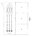
- FIG. 7 shows an exemplary view 700 presented to the users 302 when acknowledging an alarm state in accordance with the diagram 400 of FIG. 4 .
- the view 700 includes video panels 702 a - c (collectively “panels 702 ”) showing real time streaming video from the non-node camera 114 ; alerts 704 indicating that an alarm has been triggered as a result of what the non-node camera 114 is recording; and an acknowledge button 706 that the second user 302 b clicks in order to acknowledge the alarm having been triggered.
- the users 302 of the system 100 may also want to share each others' views 700 and collaborate, such as by sending each other messages and talking to each other over the system 100 , while sharing views 700 .
- This shared views and collaboration application 222 accordingly allows the users 302 to share data such as view state and server to client notifications such as user messages and share requests.
- This type of data is Synchrony data that is shared in real-time.
- FIG. 5 shows a UML sequence diagram 500 in which views 700 are shared between the users 302 using the Synchrony protocol 214 .
- the diagram 500 includes six objects: the first and second users 302 a,b , the first and second clients 102 a,b to which the first and second users 302 a,b are respectively connected, and the first and second servers 104 a,b to which the first and second clients 102 a,b are respectively connected.
- the first user 302 a logs into the first server 104 a via the first client 102 a (message 502 ), following which the first server 104 a joins the ClientNotification Synchrony ring (frame 504 ).
- the second user 302 b logs into the second server 104 b via the second client 102 b (message 506 ), following which the second server 104 b also joins the ClientNotification Synchrony ring (frame 508 ).
- the first user 302 a then instructs the first client 102 a that he wishes to share his view 700 .
- the first user 302 a does this by clicking a share button (message 510 ), which causes the first client 102 a to open the view 700 to be shared (“shared view 700 ”) on the first server 104 a (message 512 ).
- the first server 104 a creates a shared view session (message 514 ), and then sends the session identifier to the first client 102 a (message 516 ).
- each of the clients 102 joins a Synchrony ring that allows them to share the shared view 700 .
- the first server 104 a joins the SharedView 1 Synchrony ring at frame 520 .
- the first client 106 a instructs the first server 104 a to announce to the other server 104 b via the Synchrony protocol 214 that the first user 302 a 's view 700 can be shared by passing to the first server 104 a a user list and the session identifier (message 522 ).
- the first server 104 a does this by sending a message to the second server 104 b via the ClientNotify Synchrony ring that causes the second server 104 to change to a NotifyViewSession state (frame 524 ).
- the second server 104 b causes the second client 106 b to prompt the second user 302 b to share the first user 302 a 's view 700 (messages 526 and 528 ), and the second user 302 b 's affirmative response is relayed back to the second server 104 b (messages 530 and 532 ).
- the second server 104 b subsequently joins the SharedView 1 Synchrony ring (frame 534 ), which is used to share the first user 302 a 's view 700 .
- the users 106 each update the shared view 700 , and the updates are shared automatically with each other.
- the first user 302 a zooms into a first panel 702 a in the shared view 700 (message 536 ), and the first client 102 a relays to the first server 104 a how the first user 302 a zoomed into the first panel 702 a (message 538 ).
- the first server 104 a shares the zooming particulars with the second server 104 b by passing them along the SharedView 1 Synchrony ring (frame 540 ).
- the second server 104 b accordingly updates the shared view 700 as displayed on the second client 106 b (message 542 ), and the updated shared view 700 is then displayed to the second user 302 b (message 544 ). Simultaneously, the second user 302 b pans a second panel 702 b in the shared view 700 (message 546 ), and the second client 102 b relays to the second server 104 b how the second user 302 b panned this panel 702 b (message 548 ). The second server 104 b then shares the panning particulars with the first server 104 a by passing them using the SharedView 1 Synchrony ring (frame 550 ). The first server 104 a accordingly updates the shared view 700 as displayed on the first client 106 b (message 552 ), and the updated shared view 700 is then displayed to the first user 302 a (message 556 ).
- the first user 302 a closes his view 700 (message 556 ), which is relayed to the first server 104 a (message 558 ).
- the first server 104 a consequently leaves the SharedView 1 Synchrony ring (message and frame 560 ).
- the second user 302 b similarly closes his view 700 , which causes the second server 104 b to leave the SharedView 1 Synchrony ring (messages 562 and 564 , and message and frame 566 ).
- the users 302 pan and zoom the shared view 700 .
- the users 302 may modify the shared view 700 in other ways.
- the users 302 may each change the layout of the panels 702 ; choose whether video is to be displayed live or in playback mode, in which case the users 302 are also able to pause, play, or step through the video; and display user objects such as maps or web pages along with information about the user object such as revision history.
- examples of additional state information that is synchronized using a Synchrony ring include whether a video is being played, paused, or stepped through and the revision history of the user object.
- this application 222 may be implemented in a physical security system that has multiple servers 104 , such as a federated system that includes a centralized gateway server.
- FIG. 12 depicts an exemplary method 1200 for sharing a view using a physical security system that comprises a plurality of server nodes.
- the method 1200 begins at block 1202 and proceeds to block 1204 , where view state data representative of the view displayed by the first client (such as the first client 102 a ), which is the view to be shared, is sent from the first client to a first server node (such as the first server 104 a and the view state data sent via message 538 ).
- the view state data is relayed from the first server node to a second client (such as the second client 102 b ) via a second server node (such as the second server 104 b and the view state data sent via frame 540 and message 542 ).
- the second client updates a display using the view state data to show the shared view (such as via message 544 ).
- updated view state data is sent from the second client to the second server node (such as via message 548 ).
- the updated view state data is representative of the shared view as displayed by the second client.
- the updated view state data is sent from the second server node to the first client via the first server node at block 1212 (such as via frame 550 and message 552 ), and at block 1214 the first client's display is then updated to show the shared view as it was modified at the second client using the updated view state data (such as via message 554 ).
- the method 1200 ends at block 1216 .
- all the view state data may be routed through that centralized server.
- the users 302 of the system 100 may also want to be able to see and control a view on a display that is directly connected to one of the servers 104 that the users 302 do not directly control (i.e., that the users 302 control via other servers 104 ) (this display is an “unattended display”, and the view on the unattended display is the “unattended view”).
- this display is an “unattended display”, and the view on the unattended display is the “unattended view”.
- the unattended display may be mounted on a wall in front of the users 302 and be connected to the server cluster 108 via one of the servers 104 in the cluster 108 , while the users 302 may be connected to the server cluster 108 via other servers 104 in the cluster 108 .
- this display is an “unattended display”
- the view on the unattended display is the “unattended view”.
- the unattended display may be mounted on a wall in front of the users 302 and be connected to the server cluster 108 via one
- the unattended view sharing application 225 permits the users 302 to view and control the unattended view notwithstanding that none of the users 302 is directly connected to the server 104 controlling the unattended view.
- the view data exchanged between the servers 104 to enable this functionality is Synchrony data that is shared in real-time.
- FIG. 10 shows a UML sequence diagram 1000 in which the unattended view is shared with the first user 302 a using the Synchrony protocol 214 .
- the diagram 1000 includes six objects: the first user 302 a , the first client 102 a to which the first user 302 a is connected and that includes a display (“client display”) with which the first user 302 a interacts, the first and second servers 104 a,b , a monitor instance 1004 running on hardware such as an unattended one of the clients 102 connected to both the second server 104 b and the unattended display, and an administrator 1002 who sets up the monitor instance 1004 .
- client display a display
- the administrator 1002 creates the monitor instance 1004 (message 1006 ) and the monitor instance 1004 then automatically logs into the second server 104 b (messages 1008 and 1010 ).
- the monitor instance 1004 makes the unattended view available to the second server 104 b by calling Shared ViewOpen(viewState) on the second server 104 , where viewState is view state data indicative of the unattended view (message 1012 ).
- viewState is view state data indicative of the unattended view
- the second server 104 b creates a shared view session (message 1014 ) by running SharedViewSessionCreate( ) and then sends the corresponding session identifier to the monitor instance (message 1016 ).
- the monitor instance 1004 After receiving the session identifier the monitor instance 1004 joins the SharedView 1 Synchrony ring (frame 1018 ), which is used to transmit view state data to and from the other servers 104 in the cluster 108 that are also members of the SharedView 1 Synchrony ring.
- the monitor instance 1020 After joining the SharedView 1 Synchrony ring, the monitor instance 1020 publishes a notification to the other servers 104 in the cluster 108 that the unattended view is available to be seen and controlled. The monitor instance 1020 does this by calling RegisterMonitor(sessionId) on the second server 104 b (message 1018 ), which causes the session identifier related to the unattended view to be registered in a view directory (frame 1022 ). The view directory is shared with the other servers 104 in the cluster 108 using the Consistency protocol 216 .
- the view directory is disseminated to the other servers 104 in the cluster 108 , those other servers 104 can access the view directory to determine which unattended views are available to view and control.
- the first server 104 a receives the view directory, the first user 302 a via the first client 102 a logs into the first server 104 a , thereby gaining access to the cluster 108 (messages 1024 ) and the view directory.
- the first user 102 a instructs the first client 102 a to display the unattended view by calling UIDisplayMonitor(sessionId) (message 1026 ), which causes the first client 102 a to send the unattended view's session identifier to the first server 104 a with instructions to open the unattended view (message 1028 ).
- the first server 104 a acknowledges the instructions of the first client 102 a (message 1030 ) and then joins the SharedView 1 Synchrony ring (frame 1032 ) in order to automatically receive view state data describing the current view of the unattended display (message 1034 ) and to automatically stay apprised of any subsequent changes to the unattended view.
- the first server 104 a sends updated view state data to all the servers 104 that are members of the SharedView 1 Synchrony ring (frame 1040 ), which allows all of those servers 104 to reproduce the updated version of the unattended view.
- the monitor instance 1004 then updates the unattended display to show the unattended view as modified by the first user 302 a (message 1044 ).
- the first user 302 a pans one of the panels of the unattended view.
- the first user 302 a may modify the unattended view in other ways.
- the first user 302 a may change the layout of any one or more of the unattended view's panels; choose whether video is to be displayed live or in playback mode, in which case the first user 302 a is also able to pause, play, or step through the video; and display user objects such as maps or web pages along with information about the user object such as revision history.
- examples of additional state information that is synchronized using a Synchrony ring include whether a video is being played, paused, or stepped through and the revision history of the user object.
- the monitor instances 1004 for the unattended displays may be communicative with the server cluster 108 via any of one to four of the servers 104 .
- FIG. 10 shows only the first user 302 a
- more than one of the users 302 can see and control the unattended view by also joining the SharedView 1 Synchrony ring.
- the aggregated display comprising the n ⁇ m matrix of unattended displays
- the aggregated display can be mounted in the room for simultaneous viewing several of the users 302 with each of the users 302 having the ability to control each of the unattended views.
- this application 225 may be implemented in a physical security system that has multiple servers 104 , such as a federated system that includes a centralized gateway server.
- FIG. 11 depicts an exemplary method 1100 for interacting with the unattended display in a physical security system comprising multiple server nodes.
- the method begins at block 1102 and proceeds to block 1104 where a second server node (such as the second server 104 b ) that is communicative with the unattended display sends to a first server node (such as the first server 104 a ) view state data indicative of the unattended view (such as via the Synchrony ring at frames 1020 and 1032 of FIG. 10 ).
- the method 1100 then proceeds to block 1106 where at least a portion of the unattended view is displayed on the client display (such as the update of the client display that results from message 1034 of FIG. 10 ).
- all the view state data may be routed through that centralized server.
- FIG. 6 shows a UML sequence diagram 500 in which video is streamed from the non-node camera 114 to the first user 302 a through the first and second servers 104 a,b and the first client 102 a .
- the UML diagram has five objects: the first user 302 a , the first client 102 a , the first and second servers 104 a,b , and the non-node camera 114 .
- the first client 102 a can directly communicate with the first server 104 a , but cannot directly communicate with the second server 104 b .
- the first and second servers 104 a,b can communicate directly with each other.
- the second server 104 b and the non-node camera 114 can communicate directly with each other, the first server 104 a and the non-node camera 114 cannot directly communicate.
- the second server 104 b first establishes a session with the non-node camera 114 so that video is streamed from the non-node camera 114 to the second server 104 b .
- the second server 104 b first sets up a Real Time Streaming Protocol (RTSP) session with the non-node camera 114 (messages 602 and 604 ), and instructs the non-node camera 114 to send it video (messages 606 and 608 ).
- RTSP Real Time Streaming Protocol
- the non-node camera 114 subsequently commences streaming (message 610 ).
- the first user 302 a establishes a connection with the first client 102 a (message 612 ) and then instructs the first client 102 a to open a window showing the streaming video (message 614 ).
- the first client 102 a then calls LookupRoute( ) to determine to which server 104 to connect; because the first client 102 a cannot connect directly to the second server 104 b , it sets up an RTSP connection with the first server 104 a (message 618 ).
- the first server 104 b then calls LookupRoute( ) to determine to which node to connect to access the real-time video, and determines that it should connect with the second server 104 b (message 620 ).
- the first server 104 a subsequently sets up an RTSP connection with the second server 104 b (message 622 ), and the second server 104 b returns a session identifier to the first server 104 a (message 624 ).
- the first server 104 a relays the session identifier to the first client 102 a (message 626 ).
- the first client 102 a instructs the second server 104 b to begin playing RTSP video (messages 628 to 634 ), and the second server 104 b subsequently streams video to the first user 302 a via the second server 104 b , then the first server 104 a , and then the first client 102 a (messages 636 to 640 ).
- FIG. 6 routes video from one of the non-node cameras 114 connected to one of the servers 104 in a cluster 108 to other servers 104 in the same cluster 108
- video may also be routed from one of the node cameras 106 in a cluster 108 through the other node cameras 106 in the same cluster 108 .
- the cluster membership information is persistently stored locally on each of the nodes.
- one of the nodes reboots, it automatically rejoins the cluster 108 of which it was a member prior to rebooting. This is depicted in the exemplary method 900 shown in FIG. 9 .
- one of the nodes in the cluster 108 reboots (block 902 ).
- this node accesses the persistently stored cluster membership information that identifies the cluster 108 of which it was a member prior to rebooting (block 904 ), and subsequently rejoins this cluster 108 (block 906 ) before returning to block 808 .
- Having the nodes automatically rejoin a cluster 108 following rebooting is beneficial in that it helps the system 100 recover following restarting of any one or more of its servers.
- each of the nodes persistently stores the Consistency information, upon rejoining the cluster 108 only that Consistency information that has changed since the node last left the cluster 108 is synchronized again, thereby saving bandwidth.
- node cameras 106 and non-node cameras 114 are distinct from each other, in alternative embodiments (not depicted) a single camera may be simultaneously a node camera and a non-node camera.
- FIG. 1 For example, in FIG. 1
- the first camera 106 a is a node that is a member of the third cluster 108 c ; however, if the first camera 106 a were also directly coupled to the fifth server 104 e but retained only its cluster membership information for the third cluster 108 c , the first camera 106 a would remain a member of the third cluster 108 c while simultaneously acting as a non-node camera 114 from the perspective of the fifth server 104 e.
- the processor used in the foregoing embodiments may be, for example, a microprocessor, microcontroller, programmable logic controller, field programmable gate array, or an application-specific integrated circuit.
- Examples of computer readable media are non-transitory and include disc-based media such as CD-ROMs and DVDs, magnetic media such as hard drives and other forms of magnetic disk storage, semiconductor based media such as flash media, random access memory, and read only memory.
Abstract
Description
| TABLE 1 |
| Summary of the Protocol Suite 200 |
| Receives Data from | |||
| these Protocols and | Sends Data to these | ||
| Protocol Name | Protocol Layer | Applications | Protocols |
| UDP 202 | Transport | Discovery Protocol | N/A |
| 206, Node Protocol | |||
| 210, Synchrony | |||
| Protocol 214 | |||
| TCP/HTTP 204 | Transport | Node Protocol 210, | N/A |
| Gossip Protocol 208, | |||
| Membership | |||
| Protocol 212, | |||
| Consistency | |||
| Protocol 216, Status | |||
| Protocol 218 | |||
| Discovery Protocol | Cluster Support | Node Protocol 210 | UDP 202 |
| 206 | |||
| Gossip Protocol 208 | Cluster Support | Membership | TCP/HTTP 204, |
| Protocol 212, | Node Protocol 210, | ||
| Consistency | Membership | ||
| Protocol 216, Status | Protocol 212 | ||
| Protocol 218 | |||
| Node Protocol 210 | Cluster Support | Cluster Streams | UDP 202, |
| Application 220, | TCP/HTTP 204, | ||
| Synchrony 214, | Discovery Protocol | ||
| Consistency | 206 | ||
| Protocol 216, | |||
| Membership | |||
| Protocol 212, Status | |||
| Protocol 218, Gossip | |||
| Protocol 208 | |||
| Membership | Cluster Support | Synchrony Protocol | Gossip Protocol |
| Protocol 212 | 214, Gossip Protocol | 208, Node Protocol | |
| 208, Status Protocol | 210, TCP/HTTP | ||
| 218, Consistency | 204 | ||
| Protocol 216 | |||
| Synchrony Protocol | Data Sync | Shared Views and | UDP 202, Node |
| 214 | Collaboration | Protocol 210, | |
| Application 222, | Membership | ||
| Shared Events and | Protocol 212 | ||
| Alarms Application | |||
| 224 | |||
| Consistency | Data Sync | Shared Settings | Node Protocol 210, |
| Protocol 216 | Application 226, | Membership | |
| Shared User Objects | Protocol 212, | ||
| Application 228 | Gossip Protocol | ||
| 208, TCP/HTTP | |||
| 204 | |||
| Status Protocol 218 | Data Sync | System Information | Gossip Protocol |
| (device, server, etc.) | 208, Membership | ||
| Application 230 | Protocol 212, Node | ||
| Protocol 210, | |||
| TCP/HTTP 204 | |||
- 1. Node A sends a GreetingReq message to Node B, which contains a list of digests for all the nodes in the cluster 108 of which Node A is aware. For each node, a digest includes a unique node identifier and version information that is incremented each time either the heartbeat state or application state for that node changes. The version information may be, for example, a one-dimensional version number or a multi-dimensional version vector. Using a version vector allows the digest to summarize the history of the state changes that the node has undergone.
- 2. Node B sends a GreetingRsp message to Node A, which contains:
- (a) a list of digests for nodes about which Node B wishes to receive more information from Node A, which Node B determines from the version information sent to it in the GreetingReq message;
- (b) a list of digests for nodes about which Node A does not know form part of the cluster 108;
- (c) a list of one or both of heartbeat and application states that will bring Node A up-to-date on nodes for which it has out-of-date information; and
- (d) a list of nodes that Node A believes form part of the cluster 108 but that Node B knows have been removed from the cluster 108.
- 3. Node A then sends a ClosureReq message to Node B, in which Node A sends:
- (a) a list of digests for nodes about which Node A wishes to receive more information from Node B (e.g. Node A may request information for nodes of which Node A was unaware until Node B sent Node A the GreetingRsp message);
- (b) a list of states that will bring Node B up-to-date on nodes for which it has out-of-date information; and
- (c) a list of nodes that Node B believes form part of the cluster 108 but that Node A knows have been removed from the cluster 108.
- 4. Node B then sends a ClosureRsp message to Node A, in which Node B sends:
- (a) a list of states that will bring Node A up-to-date on nodes it is out-of-date on, in response to Node A's request in ClosureReq; and
- (b) a list of nodes that have been removed from the cluster 108 since GreetingRsp.
- 1. via a “Poke exchange”, as described in further detail below;
- 2. via the
Discovery protocol 206, which notifies theNode protocol 210 when a node joins or leaves thesystem 100. When a node joins the system 100 a “Poke exchange” is performed with that node; and - 3. manually, in response to user input.
- 1. a Poke request, in which Node A sends to Node B a Node A self view and a list of other nodes known to Node A, as viewed by Node A, following which Node B updates its network map in view of this information; and
- 2. a Poke response, in which Node B sends to Node A a Node B self view and a list of other nodes known to Node B, as viewed by Node B, following which Node A updates its network map in view of this information.
- 1. A membership list of all the nodes of the cluster 108, in which each of the nodes is represented by:
- (a) the node identifier, which is unique among all the nodes in the
system 100; - (b) the node's state, which is any one of:
- (i) Discover: the node is a member of the cluster 108 but has not been synchronized with the other members of the cluster 108 since having booted;
- (ii) Joining: the node is in the process of joining a cluster 108;
- (iii) Syncing: the node is in the process of synchronizing data using the Synchrony, Consistency, and
Status protocols - (iv) Valid: the node has completed synchronizing the cluster membership information and is a valid node of the cluster 108; and
- (v) TimedOut: the node has become unresponsive and is no longer an active member of the cluster 108 (the node remains a member of the cluster 108 until removed by a user);
- (c) a session token;
- (d) the version number of the cluster membership information when the node joined the cluster 108; and
- (e) the version number of the cluster membership information the last time it was changed.
- (a) the node identifier, which is unique among all the nodes in the
- 2. A gravestone list listing all the nodes that have been removed from the cluster 108, in which each removed node is represented by:
- (a) that node's node identifier; and
- (b) the version of that node's cluster membership information when the node was removed.
- 1. Node A sends a cluster secret to Node B, which in the depicted embodiment is a key that Node B requires before letting another node join its cluster 108. One of the
clients 102 provides the cluster secret to Node A. As Node B controls Node A's access to the cluster 108, Node B acts as a “membership control node”. - 2. Nodes A and B exchange their membership information. The versions of the membership information on Nodes A and B are updated to include the node identifiers of Node A and of all the nodes of the cluster 108 that Node A is joining.
- 3. Node A's state is changed to “Joining” as Node A joins the cluster.
- 4. Once joined, Node A's state is changed to “Syncing” as data is exchanged between Node A and the cluster 108 it has just joined. Node B also updates the version of the membership information stored on the all the other nodes of the cluster 108 using the Status protocol 218. The process of updating the versions of the membership information stored on Node A and all the members of the cluster 108 that Node A is joining is referred to as “synchronizing” the versions of the membership information stored on all of these nodes.
- 5. After synchronization is complete, Node A's state changes to Valid.
Data Synchronization Layer
- 1. The
Synchrony protocol 214 uses both a service identifier and a ring identifier to identify a Synchrony ring. The service identifier identifies all instances of a given Synchrony ring, whereas the ring identifier identifies a particular instance of a given Synchrony ring. For example, each time a node joins or leaves a Synchrony ring that ring's ring identifier will change, but not its service identifier. The service identifier allows a node to multicast totally ordered messages to the group of nodes that share the same service identifier (i.e. the group of nodes that belong to the same Synchrony ring). - 2. In the Totem protocol, in some cases when the nodes are not sending messages the Synchrony ring seen by nodes does not reflect the final ring configuration that converges when the nodes begin messaging. The
Synchrony protocol 214 allows nodes to send probe messages to each other to cause Synchrony rings to converge prior to the sending of non-probe messages. - 3. The Totem protocol only allows ordered messages to be sent to all nodes that form part of a Synchrony ring. In contrast, the
Synchrony protocol 214 uses a Dispatch module that abstracts the network layer from theSynchrony protocol 214 by providing an interface to broadcast to all reachable nodes in thesystem 100; multicast to any set of nodes in thesystem 100 using a list of destination node identifiers; and to unicast to a single node in thesystem 100 using its node identifier. The Dispatch module also supports multiplexing of services on the same IP port using message filtering and routing by service identifier. Outgoing messages from a node are sent to the subset of nodes having the same service identifier unless multicast. - 4. The
Synchrony protocol 214 uses fragmented messages and user payload chunking and coalescing to address problems arising from the maximum transmission unit size of approximately 1,500 bytes. - 5. The
Synchrony protocol 214 modifies the way nodes use Join messages, which are messages nodes use in the Totem protocol to join a Synchrony ring:- (a) Join messages are sent by nodes only if they have the lowest node identifier in the current set of operational nodes in the Synchrony ring.
- (b) Nodes that do not have the lowest node identifier in their operational set unicast Join messages to the nodes with the lowest node identifier in their operational set.
- (c) Join messages include the service identifier, and nodes that are not part of the corresponding Synchrony ring do not respond.
- Relative to the Totem protocol, these modifications help reduce aggregate bandwidth used by nodes to join Synchrony rings.
- 6. The
Synchrony protocol 214 detects and blacklists nodes that are unable to join a Synchrony ring due to some types of network misconfigurations. For example, a node that is able to send to, but not receive messages from, the other nodes will appear to the other nodes to only ever send probe messages since all other messages in the present embodiment are solicited, and accordingly will be blacklisted. - 7. The
Synchrony protocol 214 performs payload encryption and authenticity verification of messages. - 8. The
Synchrony protocol 214 limits the time each node can hold the token used in the Totem protocol; in the depicted embodiment, each node can hold the token for 15 ms. - 9. The
Synchrony protocol 214 implements a TCP friendly congestion avoidance algorithm.
- 1 SetEntries: SetEntries transmits new or updated ECEs to a node, which inserts them into the appropriate ECDs.
- 2. GetEntries: GetEntries transmits a key or a range of keys to a node, which returns the ECEs corresponding to those one or more keys.
- 3. SynEntries: SynEntries transmits a key or a range of keys to a node, and the two nodes then compare hashes of successively decreasing ranges of ECEs to determine which ECEs differ between the two nodes, as described above. If the ECEs differ, the nodes merge their ECEs so that the same ECEs are stored on the nodes by comparing the ITC timestamps; if the ITC timestamps match, the nodes compare the UTC timestamps associated with the ECEs. These timestamps act as version information that allows the two nodes to adopt the ECEs that have been most recently modified, as indicated by those ECEs' version information.
Claims (21)
Priority Applications (2)
| Application Number | Priority Date | Filing Date | Title |
|---|---|---|---|
| US14/005,240 US9602582B2 (en) | 2012-09-07 | 2013-09-06 | Physical security system having multiple server nodes |
| US15/087,663 US10547693B2 (en) | 2012-09-07 | 2016-03-31 | Security device capability discovery and device selection |
Applications Claiming Priority (3)
| Application Number | Priority Date | Filing Date | Title |
|---|---|---|---|
| US13/607,447 US10454997B2 (en) | 2012-09-07 | 2012-09-07 | Distributed physical security system |
| PCT/CA2013/050690 WO2014036656A1 (en) | 2012-09-07 | 2013-09-06 | Physical security system having multiple server nodes |
| US14/005,240 US9602582B2 (en) | 2012-09-07 | 2013-09-06 | Physical security system having multiple server nodes |
Related Parent Applications (2)
| Application Number | Title | Priority Date | Filing Date |
|---|---|---|---|
| US13/607,447 Continuation-In-Part US10454997B2 (en) | 2012-09-07 | 2012-09-07 | Distributed physical security system |
| PCT/CA2013/050690 A-371-Of-International WO2014036656A1 (en) | 2012-09-07 | 2013-09-06 | Physical security system having multiple server nodes |
Related Child Applications (1)
| Application Number | Title | Priority Date | Filing Date |
|---|---|---|---|
| US15/087,663 Continuation-In-Part US10547693B2 (en) | 2012-09-07 | 2016-03-31 | Security device capability discovery and device selection |
Publications (2)
| Publication Number | Publication Date |
|---|---|
| US20140222892A1 US20140222892A1 (en) | 2014-08-07 |
| US9602582B2 true US9602582B2 (en) | 2017-03-21 |
Family
ID=50234512
Family Applications (2)
| Application Number | Title | Priority Date | Filing Date |
|---|---|---|---|
| US13/607,447 Active 2034-01-02 US10454997B2 (en) | 2012-09-07 | 2012-09-07 | Distributed physical security system |
| US14/005,240 Active 2033-05-29 US9602582B2 (en) | 2012-09-07 | 2013-09-06 | Physical security system having multiple server nodes |
Family Applications Before (1)
| Application Number | Title | Priority Date | Filing Date |
|---|---|---|---|
| US13/607,447 Active 2034-01-02 US10454997B2 (en) | 2012-09-07 | 2012-09-07 | Distributed physical security system |
Country Status (19)
| Country | Link |
|---|---|
| US (2) | US10454997B2 (en) |
| EP (1) | EP2893669B1 (en) |
| JP (1) | JP6500289B2 (en) |
| KR (1) | KR102108595B1 (en) |
| CN (2) | CN110598444B (en) |
| AU (1) | AU2013312982B2 (en) |
| BR (1) | BR112015004429B1 (en) |
| CA (1) | CA2883662C (en) |
| HK (1) | HK1212118A1 (en) |
| IL (1) | IL237439B (en) |
| IN (1) | IN2015DN01665A (en) |
| MX (1) | MX352801B (en) |
| MY (1) | MY181255A (en) |
| NZ (1) | NZ705517A (en) |
| RU (1) | RU2653294C2 (en) |
| SA (1) | SA515360089B1 (en) |
| SG (1) | SG11201501489UA (en) |
| WO (1) | WO2014036656A1 (en) |
| ZA (1) | ZA201501340B (en) |
Cited By (1)
| Publication number | Priority date | Publication date | Assignee | Title |
|---|---|---|---|---|
| US20160019051A1 (en) * | 2012-10-02 | 2016-01-21 | Oracle International Corporation | Forcibly completing upgrade of distributed software in presence of failures |
Families Citing this family (39)
| Publication number | Priority date | Publication date | Assignee | Title |
|---|---|---|---|---|
| US10181974B2 (en) * | 2012-12-04 | 2019-01-15 | Genesys Telecommunications Laboratories, Inc. | Distributed agent reservation in SIP cluster |
| US9369670B2 (en) * | 2012-12-19 | 2016-06-14 | Rabbit, Inc. | Audio video streaming system and method |
| CN104010160B (en) * | 2013-02-25 | 2017-10-13 | 杭州海康威视系统技术有限公司 | The Trunk pipeline method and its device of video monitoring system |
| US9641498B2 (en) | 2013-03-07 | 2017-05-02 | Fiserv, Inc. | Single sign-on processing for associated mobile applications |
| US9015328B2 (en) * | 2013-03-07 | 2015-04-21 | Fiserv, Inc. | Single sign-on processing for associated mobile applications |
| US10038626B2 (en) * | 2013-04-16 | 2018-07-31 | Amazon Technologies, Inc. | Multipath routing in a distributed load balancer |
| US9852230B2 (en) * | 2013-06-29 | 2017-12-26 | Google Llc | Asynchronous message passing for large graph clustering |
| US10878323B2 (en) | 2014-02-28 | 2020-12-29 | Tyco Fire & Security Gmbh | Rules engine combined with message routing |
| US9792129B2 (en) | 2014-02-28 | 2017-10-17 | Tyco Fire & Security Gmbh | Network range extender with multi-RF radio support for plurality of network interfaces |
| US10140118B2 (en) | 2014-03-19 | 2018-11-27 | Huawei Device (Dongguan) Co., Ltd. | Application data synchronization method and apparatus |
| US9513364B2 (en) | 2014-04-02 | 2016-12-06 | Tyco Fire & Security Gmbh | Personnel authentication and tracking system |
| CA2947164A1 (en) * | 2014-04-30 | 2015-11-05 | Cubic Corporation | Failsafe operation for unmanned gatelines |
| US10063439B2 (en) | 2014-09-09 | 2018-08-28 | Belkin International Inc. | Coordinated and device-distributed detection of abnormal network device operation |
| US9026840B1 (en) | 2014-09-09 | 2015-05-05 | Belkin International, Inc. | Coordinated and device-distributed detection of abnormal network device operation |
| WO2016061407A1 (en) | 2014-10-15 | 2016-04-21 | Avigilon Corporation | Distributed security system over multiple sites |
| WO2016161171A1 (en) * | 2015-03-31 | 2016-10-06 | Avigilon Corporation | Security device capability discovery and device selection |
| US9959109B2 (en) | 2015-04-10 | 2018-05-01 | Avigilon Corporation | Upgrading a physical security system having multiple server nodes |
| US10362106B2 (en) | 2015-07-21 | 2019-07-23 | Cisco Technology, Inc. | Adaptive gossip protocol |
| WO2017045079A1 (en) * | 2015-09-18 | 2017-03-23 | Avigilon Corporation | Physical security system having multiple server nodes configured to implement a conditionally triggered rule |
| US10095726B2 (en) * | 2016-07-22 | 2018-10-09 | Ebay Inc. | Multiple workspace database engine |
| US10346191B2 (en) * | 2016-12-02 | 2019-07-09 | Wmware, Inc. | System and method for managing size of clusters in a computing environment |
| CN107395659B (en) | 2017-03-28 | 2021-08-24 | 创新先进技术有限公司 | Method and device for service acceptance and consensus |
| EP3465579B1 (en) * | 2017-06-07 | 2019-11-20 | Nchain Holdings Limited | Credential generation and distribution method and system for a blockchain network |
| WO2019191569A1 (en) * | 2018-03-30 | 2019-10-03 | V2COM, Inc. | System and method for resource management and resource allocation in a self-optimizing network of heterogeneous processing nodes |
| RU2703154C1 (en) * | 2018-12-06 | 2019-10-15 | Общество с ограниченной ответственностью "Ай Ти Ви групп" | System and method for synchronizing on time playback of data from different devices |
| KR102018151B1 (en) * | 2018-12-12 | 2019-09-06 | 대한민국 | Disaster situation managing system based on video |
| US11159610B2 (en) * | 2019-10-10 | 2021-10-26 | Dell Products, L.P. | Cluster formation offload using remote access controller group manager |
| CN110990329B (en) * | 2019-12-09 | 2023-12-01 | 杭州趣链科技有限公司 | Federal computing high availability method, equipment and medium |
| US11593234B2 (en) | 2020-01-16 | 2023-02-28 | Vmware, Inc. | Cloud restart for VM failover and capacity management |
| US11347521B2 (en) * | 2020-01-16 | 2022-05-31 | Vmware, Inc. | Cloud restart for non-critical performance virtual machines |
| US11722589B2 (en) * | 2020-04-08 | 2023-08-08 | Huawei Technologies Co., Ltd. | Rapid ledger consensus system and method for distributed wireless networks |
| US11503381B2 (en) | 2020-06-29 | 2022-11-15 | Seagate Technology Llc | Distributed surveillance system with abstracted functional layers |
| US11463739B2 (en) | 2020-06-29 | 2022-10-04 | Seagate Technology Llc | Parameter based load balancing in a distributed surveillance system |
| US11343544B2 (en) | 2020-06-29 | 2022-05-24 | Seagate Technology Llc | Selective use of cameras in a distributed surveillance system |
| CN112202746B (en) * | 2020-09-24 | 2023-04-21 | 北京百度网讯科技有限公司 | RPC member information acquisition method, device, electronic equipment and storage medium |
| CN112910981B (en) * | 2021-01-27 | 2022-07-26 | 联想(北京)有限公司 | Control method and device |
| US11595321B2 (en) | 2021-07-06 | 2023-02-28 | Vmware, Inc. | Cluster capacity management for hyper converged infrastructure updates |
| US11914686B2 (en) | 2021-10-15 | 2024-02-27 | Pure Storage, Inc. | Storage node security statement management in a distributed storage cluster |
| CN114363357B (en) * | 2021-12-28 | 2024-01-19 | 上海沄熹科技有限公司 | Distributed database network connection management method based on Gossip |
Citations (42)
| Publication number | Priority date | Publication date | Assignee | Title |
|---|---|---|---|---|
| US6691154B1 (en) * | 1998-11-18 | 2004-02-10 | Webex Communications, Inc. | Instantaneous remote control of an unattended server |
| US20040221149A1 (en) | 2003-04-29 | 2004-11-04 | Rao Sudhir G. | Storage system and cluster maintenance |
| US20050091396A1 (en) | 2003-08-05 | 2005-04-28 | Chandrasekharan Nilakantan | Method and apparatus for achieving dynamic capacity and high availability in multi-stage data networks using adaptive flow-based routing |
| US20050144186A1 (en) * | 1999-12-02 | 2005-06-30 | Lambertus Hesselink | Managed peer-to-peer applications, systems and methods for distributed data access and storage |
| US20060015599A1 (en) * | 2004-06-30 | 2006-01-19 | Li Shih T | Multi-layer video management and display method carried out on the networks |
| US20060271624A1 (en) * | 2005-05-12 | 2006-11-30 | International Business Machines Corporation | Method, system, and computer program product for web conference participant display render acknowledgement |
| US20070005809A1 (en) * | 2001-09-14 | 2007-01-04 | Youichi Kobayashi | Network information processing system and network information processing method |
| US7185076B1 (en) | 2000-05-31 | 2007-02-27 | International Business Machines Corporation | Method, system and program products for managing a clustered computing environment |
| US20070261102A1 (en) * | 2006-05-04 | 2007-11-08 | Tony Spataro | Methods and systems for specifying and enforcing access control in a distributed system |
| US20070285501A1 (en) * | 2006-06-09 | 2007-12-13 | Wai Yim | Videoconference System Clustering |
| US20080068290A1 (en) * | 2006-09-14 | 2008-03-20 | Shadi Muklashy | Systems and methods for multiple display support in remote access software |
| US20080084473A1 (en) | 2006-10-06 | 2008-04-10 | John Frederick Romanowich | Methods and apparatus related to improved surveillance using a smart camera |
| US20080270569A1 (en) | 2007-04-25 | 2008-10-30 | Miovision Technologies Incorporated | Method and system for analyzing multimedia content |
| US20090080443A1 (en) | 2007-09-21 | 2009-03-26 | Honeywell International, Inc. | System and method for remotely administering and synchronizing a clustered group of access control panels |
| US20090182610A1 (en) | 2008-01-11 | 2009-07-16 | Oracle International Corporation | System and method for asset registration workflows utilizing an eventing infrastructure in a metadata repository |
| US20100124271A1 (en) | 2008-11-18 | 2010-05-20 | Andrew Martz | Method, system and apparatus for image capture, analysis and transmission |
| US20100161758A1 (en) * | 2008-12-22 | 2010-06-24 | Mostafa Tofigh | Method and apparatus for enabling content sharing among endpoint devices |
| US20100312879A1 (en) | 2009-06-09 | 2010-12-09 | International Business Machines Corporation | Plug-in provisioning integration in a clustered environment |
| US20110026513A1 (en) | 2009-07-31 | 2011-02-03 | Chien-Wen Tien | Method and system for synchronizing a data base at a plurality of nodes in an ad hoc network |
| US20110141280A1 (en) | 2009-12-14 | 2011-06-16 | China Telecom Corporation Limited | Sip-based network video surveillance system and method |
| US20110231524A1 (en) | 2010-03-17 | 2011-09-22 | Hitachi, Ltd. | Metadata management method for nas global namespace design |
| US20120079092A1 (en) | 2009-12-28 | 2012-03-29 | Telefonaktiebolaget L M Ericsson (Publ) | Management of data flows between user equipment nodes and clusters of networked resource nodes |
| US20120092510A1 (en) * | 2009-03-04 | 2012-04-19 | Honeywell International Inc. | Systems and methods for managing video data |
| US20120158894A1 (en) | 2010-12-21 | 2012-06-21 | Desgagne Yves | Video stream distribution |
| US20120259912A1 (en) | 2011-04-07 | 2012-10-11 | Microsoft Corporation | Cluster unique identifier |
| US20120278422A1 (en) | 2011-04-26 | 2012-11-01 | Oracle International Corporation | Live object pattern for use with a distributed cache |
| US20120303737A1 (en) | 2008-09-18 | 2012-11-29 | Avere Systems, Inc. | System and Method for Storing Data in Clusters Located Remotely From Each Other |
| US20120317274A1 (en) | 2011-06-13 | 2012-12-13 | Richter Owen E | Distributed metering and monitoring system |
| US20120314127A1 (en) | 2011-06-09 | 2012-12-13 | Inayat Syed | Provisioning network resources responsive to video requirements of user equipment nodes |
| US20130024901A1 (en) | 2009-09-26 | 2013-01-24 | Disternet Technology, Inc. | Method and system for processing multi-media content |
| US20130073717A1 (en) | 2011-09-15 | 2013-03-21 | International Business Machines Corporation | Optimizing clustered network attached storage (nas) usage |
| US20130113928A1 (en) | 2011-11-08 | 2013-05-09 | Joseph Feldman | Computerized System and Method for Monitoring a Door of a Facility from Afar |
| US20130132848A1 (en) * | 2011-11-18 | 2013-05-23 | Apple Inc. | Application interaction via multiple user interfaces |
| US20130185408A1 (en) | 2012-01-18 | 2013-07-18 | Dh2I Company | Systems and Methods for Server Cluster Application Virtualization |
| US20130276061A1 (en) * | 2007-09-05 | 2013-10-17 | Gopi Krishna Chebiyyam | System, method, and computer program product for preventing access to data with respect to a data access attempt associated with a remote data sharing session |
| US20130307971A1 (en) | 2012-05-16 | 2013-11-21 | Cisco Technology, Inc. | System and method for video recording and retention in a network |
| US20130307989A1 (en) | 2012-05-20 | 2013-11-21 | Transportation Security Enterprises, Inc. (Tse) | System and method for real-time data capture and packet transmission using a layer 2 wireless mesh network |
| US8601112B1 (en) | 2006-03-14 | 2013-12-03 | Amazon Technologies, Inc. | Method and system for collecting and analyzing time-series data |
| US20130329050A1 (en) | 2012-06-07 | 2013-12-12 | Verizon Patent And Licensing Inc. | Remote streaming |
| US20140025770A1 (en) | 2012-07-17 | 2014-01-23 | Convergent.Io Technologies Inc. | Systems, methods and devices for integrating end-host and network resources in distributed memory |
| US8675672B1 (en) | 2011-12-30 | 2014-03-18 | Emc Corporation | Hierarchical cluster tree overlay network |
| US20140136701A1 (en) * | 2012-11-13 | 2014-05-15 | International Business Machines Corporation | Distributed Control of a Heterogeneous Video Surveillance Network |
Family Cites Families (16)
| Publication number | Priority date | Publication date | Assignee | Title |
|---|---|---|---|---|
| US5999712A (en) | 1997-10-21 | 1999-12-07 | Sun Microsystems, Inc. | Determining cluster membership in a distributed computer system |
| US6801949B1 (en) * | 1999-04-12 | 2004-10-05 | Rainfinity, Inc. | Distributed server cluster with graphical user interface |
| US6564261B1 (en) * | 1999-05-10 | 2003-05-13 | Telefonaktiebolaget Lm Ericsson (Publ) | Distributed system to intelligently establish sessions between anonymous users over various networks |
| US8121148B2 (en) | 2005-03-24 | 2012-02-21 | Ixia | Protocol stack using shared memory |
| US8195976B2 (en) * | 2005-06-29 | 2012-06-05 | International Business Machines Corporation | Fault-tolerance and fault-containment models for zoning clustered application silos into continuous availability and high availability zones in clustered systems during recovery and maintenance |
| US7512707B1 (en) * | 2005-11-03 | 2009-03-31 | Adobe Systems Incorporated | Load balancing of server clusters |
| US9047310B2 (en) * | 2006-02-22 | 2015-06-02 | Microsoft Technology Licensing, Llc | Reliable, efficient peer-to-peer storage |
| US8094585B2 (en) | 2006-10-31 | 2012-01-10 | International Business Machines Corporation | Membership management of network nodes |
| CN101188569B (en) * | 2006-11-16 | 2011-05-04 | 饶大平 | Method for constructing data quanta space in network and distributed file storage system |
| US7840730B2 (en) * | 2008-06-27 | 2010-11-23 | Microsoft Corporation | Cluster shared volumes |
| US7996360B2 (en) | 2008-06-27 | 2011-08-09 | International Business Machines Corporation | Coordinating updates to replicated data |
| US20110103391A1 (en) * | 2009-10-30 | 2011-05-05 | Smooth-Stone, Inc. C/O Barry Evans | System and method for high-performance, low-power data center interconnect fabric |
| US9690818B2 (en) * | 2009-12-01 | 2017-06-27 | Sybase, Inc. | On demand locking of retained resources in a distributed shared disk cluster environment |
| CN101873237B (en) | 2010-06-13 | 2012-02-22 | 用友软件股份有限公司 | Method and system for dynamically maintaining member servers in cluster |
| CN102035672B (en) * | 2010-11-26 | 2013-03-27 | 中国科学院声学研究所 | Distributed network measurement method based on hierarchical coordination multi-agent system |
| CN102025550A (en) | 2010-12-20 | 2011-04-20 | 中兴通讯股份有限公司 | System and method for managing data in distributed cluster |
-
2012
- 2012-09-07 US US13/607,447 patent/US10454997B2/en active Active
-
2013
- 2013-09-06 BR BR112015004429-8A patent/BR112015004429B1/en active IP Right Grant
- 2013-09-06 CA CA2883662A patent/CA2883662C/en active Active
- 2013-09-06 CN CN201910864051.1A patent/CN110598444B/en active Active
- 2013-09-06 US US14/005,240 patent/US9602582B2/en active Active
- 2013-09-06 RU RU2015106840A patent/RU2653294C2/en active
- 2013-09-06 MY MYPI2015000525A patent/MY181255A/en unknown
- 2013-09-06 NZ NZ705517A patent/NZ705517A/en unknown
- 2013-09-06 JP JP2015530252A patent/JP6500289B2/en active Active
- 2013-09-06 MX MX2015002735A patent/MX352801B/en active IP Right Grant
- 2013-09-06 CN CN201380058071.0A patent/CN104813609A/en active Pending
- 2013-09-06 SG SG11201501489UA patent/SG11201501489UA/en unknown
- 2013-09-06 WO PCT/CA2013/050690 patent/WO2014036656A1/en active Application Filing
- 2013-09-06 KR KR1020157008926A patent/KR102108595B1/en active IP Right Grant
- 2013-09-06 AU AU2013312982A patent/AU2013312982B2/en active Active
- 2013-09-06 EP EP13835467.5A patent/EP2893669B1/en active Active
- 2013-09-06 IN IN1665DEN2015 patent/IN2015DN01665A/en unknown
-
2015
- 2015-02-26 IL IL237439A patent/IL237439B/en active IP Right Grant
- 2015-02-27 ZA ZA201501340A patent/ZA201501340B/en unknown
- 2015-02-28 SA SA515360089A patent/SA515360089B1/en unknown
- 2015-12-18 HK HK15112537.8A patent/HK1212118A1/en unknown
Patent Citations (42)
| Publication number | Priority date | Publication date | Assignee | Title |
|---|---|---|---|---|
| US6691154B1 (en) * | 1998-11-18 | 2004-02-10 | Webex Communications, Inc. | Instantaneous remote control of an unattended server |
| US20050144186A1 (en) * | 1999-12-02 | 2005-06-30 | Lambertus Hesselink | Managed peer-to-peer applications, systems and methods for distributed data access and storage |
| US7185076B1 (en) | 2000-05-31 | 2007-02-27 | International Business Machines Corporation | Method, system and program products for managing a clustered computing environment |
| US20070005809A1 (en) * | 2001-09-14 | 2007-01-04 | Youichi Kobayashi | Network information processing system and network information processing method |
| US20040221149A1 (en) | 2003-04-29 | 2004-11-04 | Rao Sudhir G. | Storage system and cluster maintenance |
| US20050091396A1 (en) | 2003-08-05 | 2005-04-28 | Chandrasekharan Nilakantan | Method and apparatus for achieving dynamic capacity and high availability in multi-stage data networks using adaptive flow-based routing |
| US20060015599A1 (en) * | 2004-06-30 | 2006-01-19 | Li Shih T | Multi-layer video management and display method carried out on the networks |
| US20060271624A1 (en) * | 2005-05-12 | 2006-11-30 | International Business Machines Corporation | Method, system, and computer program product for web conference participant display render acknowledgement |
| US8601112B1 (en) | 2006-03-14 | 2013-12-03 | Amazon Technologies, Inc. | Method and system for collecting and analyzing time-series data |
| US20070261102A1 (en) * | 2006-05-04 | 2007-11-08 | Tony Spataro | Methods and systems for specifying and enforcing access control in a distributed system |
| US20070285501A1 (en) * | 2006-06-09 | 2007-12-13 | Wai Yim | Videoconference System Clustering |
| US20080068290A1 (en) * | 2006-09-14 | 2008-03-20 | Shadi Muklashy | Systems and methods for multiple display support in remote access software |
| US20080084473A1 (en) | 2006-10-06 | 2008-04-10 | John Frederick Romanowich | Methods and apparatus related to improved surveillance using a smart camera |
| US20080270569A1 (en) | 2007-04-25 | 2008-10-30 | Miovision Technologies Incorporated | Method and system for analyzing multimedia content |
| US20130276061A1 (en) * | 2007-09-05 | 2013-10-17 | Gopi Krishna Chebiyyam | System, method, and computer program product for preventing access to data with respect to a data access attempt associated with a remote data sharing session |
| US20090080443A1 (en) | 2007-09-21 | 2009-03-26 | Honeywell International, Inc. | System and method for remotely administering and synchronizing a clustered group of access control panels |
| US20090182610A1 (en) | 2008-01-11 | 2009-07-16 | Oracle International Corporation | System and method for asset registration workflows utilizing an eventing infrastructure in a metadata repository |
| US20120303737A1 (en) | 2008-09-18 | 2012-11-29 | Avere Systems, Inc. | System and Method for Storing Data in Clusters Located Remotely From Each Other |
| US20100124271A1 (en) | 2008-11-18 | 2010-05-20 | Andrew Martz | Method, system and apparatus for image capture, analysis and transmission |
| US20100161758A1 (en) * | 2008-12-22 | 2010-06-24 | Mostafa Tofigh | Method and apparatus for enabling content sharing among endpoint devices |
| US20120092510A1 (en) * | 2009-03-04 | 2012-04-19 | Honeywell International Inc. | Systems and methods for managing video data |
| US20100312879A1 (en) | 2009-06-09 | 2010-12-09 | International Business Machines Corporation | Plug-in provisioning integration in a clustered environment |
| US20110026513A1 (en) | 2009-07-31 | 2011-02-03 | Chien-Wen Tien | Method and system for synchronizing a data base at a plurality of nodes in an ad hoc network |
| US20130024901A1 (en) | 2009-09-26 | 2013-01-24 | Disternet Technology, Inc. | Method and system for processing multi-media content |
| US20110141280A1 (en) | 2009-12-14 | 2011-06-16 | China Telecom Corporation Limited | Sip-based network video surveillance system and method |
| US20120079092A1 (en) | 2009-12-28 | 2012-03-29 | Telefonaktiebolaget L M Ericsson (Publ) | Management of data flows between user equipment nodes and clusters of networked resource nodes |
| US20110231524A1 (en) | 2010-03-17 | 2011-09-22 | Hitachi, Ltd. | Metadata management method for nas global namespace design |
| US20120158894A1 (en) | 2010-12-21 | 2012-06-21 | Desgagne Yves | Video stream distribution |
| US20120259912A1 (en) | 2011-04-07 | 2012-10-11 | Microsoft Corporation | Cluster unique identifier |
| US20120278422A1 (en) | 2011-04-26 | 2012-11-01 | Oracle International Corporation | Live object pattern for use with a distributed cache |
| US20120314127A1 (en) | 2011-06-09 | 2012-12-13 | Inayat Syed | Provisioning network resources responsive to video requirements of user equipment nodes |
| US20120317274A1 (en) | 2011-06-13 | 2012-12-13 | Richter Owen E | Distributed metering and monitoring system |
| US20130073717A1 (en) | 2011-09-15 | 2013-03-21 | International Business Machines Corporation | Optimizing clustered network attached storage (nas) usage |
| US20130113928A1 (en) | 2011-11-08 | 2013-05-09 | Joseph Feldman | Computerized System and Method for Monitoring a Door of a Facility from Afar |
| US20130132848A1 (en) * | 2011-11-18 | 2013-05-23 | Apple Inc. | Application interaction via multiple user interfaces |
| US8675672B1 (en) | 2011-12-30 | 2014-03-18 | Emc Corporation | Hierarchical cluster tree overlay network |
| US20130185408A1 (en) | 2012-01-18 | 2013-07-18 | Dh2I Company | Systems and Methods for Server Cluster Application Virtualization |
| US20130307971A1 (en) | 2012-05-16 | 2013-11-21 | Cisco Technology, Inc. | System and method for video recording and retention in a network |
| US20130307989A1 (en) | 2012-05-20 | 2013-11-21 | Transportation Security Enterprises, Inc. (Tse) | System and method for real-time data capture and packet transmission using a layer 2 wireless mesh network |
| US20130329050A1 (en) | 2012-06-07 | 2013-12-12 | Verizon Patent And Licensing Inc. | Remote streaming |
| US20140025770A1 (en) | 2012-07-17 | 2014-01-23 | Convergent.Io Technologies Inc. | Systems, methods and devices for integrating end-host and network resources in distributed memory |
| US20140136701A1 (en) * | 2012-11-13 | 2014-05-15 | International Business Machines Corporation | Distributed Control of a Heterogeneous Video Surveillance Network |
Non-Patent Citations (35)
| Title |
|---|
| "Project Voldemort-A distributed database," as available at: http://www.project-voldemort.com/, on Dec. 16, 2013. |
| "Project Voldemort-A distributed database," as available at: http://www.project-voldemort.com/, on Sep. 2, 2012. |
| "Riak" as available at: http://www.basho.com/Riak.html, on Dec. 16, 2013. |
| Almeida, et al. "Interval tree clocks: a logical clock for dynamic systems" Principles of Distributed Systems. Springer Berlin Heidelberg, pp. 259-274, 2008. |
| Amir, et al. "Efficient State Transfer in Partitionable Environments," Institute of Computer Science, The Hebrew University. 1997. |
| Amir, et al. "The Totem Single-Ring Ordering and Membership Protocol," ACM Transactions on Computer Systems, vol. 13, No. 4, pp. 311-342, 1995. |
| Berners-Lee, et al. "Uniform Resource Identifier (URI): Generic Syntax," The Internet Society (2005) as available at: http://tools.ietf.org/html/rfc3986, on Dec. 16, 2013. |
| Berners-Lee, et al. "Uniform Resource Identifier (URI): Generic Syntax," The Internet Society (2005) as available at: http://tools.ietf.org/html/rfc3986, on Sep. 2, 2012. |
| Birman. "Chapter 6: A history of the virtual synchrony replication model." Replication. Springer Berlin Heidelberg, pp. 91-120, 2010. |
| DeCandia, et al. "Dynamo: amazon's highly available key-value store." ACM SIGOPS Operating Systems Review. vol. 41. No. 6. ACM, 2007. |
| European Search Report for Application No. 13835467.5, mailed by the European Patent Office on Jun. 28, 2016 (6 pages). |
| Google Developers. "Protocol Buffers," as available at: https://developers.google.com/protocol-buffers/docs/encoding, on Dec. 16, 2013. |
| Google Developers. "Protocol Buffers," as available at: https://developers.google.com/protocol-buffers/docs/encoding, on Jun. 2, 2012. |
| International Search Report and Written Opinion for Application No. PCT/CA2013/050690, mailed by the Canadian Intellectual Property Office as ISA on Dec. 12, 2013 (11 pages). |
| Leach, et al. "A Universally Unique Identifier (UUID) URN Namespace," The Internet Society (2005), as available at: http://tools.ietf.org/html/rfc4122, on Dec. 16, 2013. |
| Leach, et al. "A Universally Unique Identifier (UUID) URN Namespace," The Internet Society (2005), as available at: http://tools.ietf.org/html/rfc4122, on Sep. 4, 2012. |
| Moser, et al. "Extended Virtual Synchrony." Distributed Computing Systems, 1994, Proceedings of the 14th International Conference on. IEEE, 1994. |
| OASIS Web Services Dynamic Discovery (WS-Discovery) Version 1.1, OASIS Standard, as available at: http://docs.oasis-open.org/ws-dd/discovery/1.1/os/wsdd-discovery-1.1-spec-os.pdf, on Jul. 1, 2009. |
| Office action dated , issued by the United States Patent and Trademark Office in related U.S. Appl. No. 13/607,447, filed Sep. 7, 2012. |
| Office action dated Apr. 14, 2015, issued by the United States Patent and Trademark Office in related U.S. Appl. No. 13/607,447, filed Sep. 7, 2012. |
| The Apache Software Foundation, "Cassandra," (2009) as available at: http://cassandra.apache.org/, on Dec. 16, 2013. |
| The Apache Software Foundation, "Cassandra," (2009) as available at: http://cassandra.apache.org/, on Sep. 5, 2012. |
| Van Renesse, et al. "A Gossip-Style Failure Detection Service," IFIP International Conference on Distributed Systems Platforms and Open Distributed Processing, pp. 55-70, 1998. |
| Van Renesse, et al. "Efficient Reconciliation and Flow Control for Anti-Entropy Protocols." Proceedings of the 2nd Workshop on Large-Scale Distributed Systems and Middleware. ACM, 2008. |
| Wikipedia. "Galois/Counter Mode," as available at: http://en.wikipedia.org/wiki/Galois/Counter-Mode, on Aug. 17, 2012. |
| Wikipedia. "Galois/Counter Mode," as available at: http://en.wikipedia.org/wiki/Galois/Counter-Mode, on Dec. 16, 2013. |
| Wikipedia. "Gossip Protocol," as available at: http://en.wikipedia.org/wiki/Gossip-protocol, on Dec. 16, 2013. |
| Wikipedia. "Gossip Protocol," as available at: http://en.wikipedia.org/wiki/Gossip-protocol, on Jul. 16, 2012. |
| Wikipedia. "Maximum Transmission Unit," as available at: http://en.wikipedia.org/wiki/Maximum-transmission-unit, on Aug. 27, 2012. |
| Wikipedia. "Maximum Transmission Unit," as available at: http://en.wikipedia.org/wiki/Maximum-transmission-unit, on Dec. 16, 2013. |
| Wikipedia. "Virtual Synchrony," as available at: http://en.wikipedia.org/wiki/Virtual-synchrony, on accessed Dec. 16, 2013. |
| Wikipedia. "Virtual Synchrony," as available at: http://en.wikipedia.org/wiki/Virtual-synchrony, on accessed Jun. 15, 2012. |
| Wikipedia. "WS-Discovery," as available at: http://en.wikipedia.org/wiki/WS-Discovery, on Apr. 5, 2012. |
| Wikipedia. "WS-Discovery," as available at: http://en.wikipedia.org/wiki/WS-Discovery, on Dec. 16, 2013. |
| Zhou, et al. "An Efficient Topology-Adaptive Membership Protocol for Large-Scale Cluster-Based Services," Parallel and Distributed Processing Symposium, 2005. Proceedings. 19th IEEE International. IEEE, 2005. |
Cited By (2)
| Publication number | Priority date | Publication date | Assignee | Title |
|---|---|---|---|---|
| US20160019051A1 (en) * | 2012-10-02 | 2016-01-21 | Oracle International Corporation | Forcibly completing upgrade of distributed software in presence of failures |
| US10019250B2 (en) * | 2012-10-02 | 2018-07-10 | Oracle International Corporation | Forcibly completing upgrade of distributed software in presence of failures |
Also Published As
Similar Documents
| Publication | Publication Date | Title |
|---|---|---|
| US9602582B2 (en) | Physical security system having multiple server nodes | |
| US10474449B2 (en) | Upgrading a physical security system having multiple server nodes | |
| US10547693B2 (en) | Security device capability discovery and device selection | |
| US9979791B2 (en) | Physical security system having multiple server nodes configured to implement a conditionally triggered rule | |
| Oktian et al. | Distributed SDN controller system: A survey on design choice | |
| US10810863B2 (en) | Distributed security system over multiple sites | |
| EP1360796B1 (en) | Method and system for a set of network appliances which can be connected to provide enhanced collaboration, scalability, and reliability | |
| TWI364218B (en) | Real-time image monitoring and recording system and method | |
| CN102984501A (en) | Network video-recording cluster system |
Legal Events
| Date | Code | Title | Description |
|---|---|---|---|
| AS | Assignment |
Owner name: AVIGILON CORPORATION, CANADA Free format text: ASSIGNMENT OF ASSIGNORS INTEREST;ASSIGNORS:ADAM, MATTHEW;LEE, RYAN;REEL/FRAME:032253/0769 Effective date: 20140212 Owner name: AVIGILON CORPORATION, CANADA Free format text: ASSIGNMENT OF ASSIGNORS INTEREST;ASSIGNORS:MARTZ, ANDREW;WIGHTMAN, ROSS;MAGOLAN, GREG;AND OTHERS;REEL/FRAME:032253/0785 Effective date: 20120907 |
|
| AS | Assignment |
Owner name: HSBC BANK CANADA, CANADA Free format text: SECURITY INTEREST;ASSIGNOR:AVIGILON CORPORATION;REEL/FRAME:035389/0328 Effective date: 20150407 |
|
| AS | Assignment |
Owner name: HSBC BANK CANADA, CANADA Free format text: CORRECTIVE ASSIGNMENT TO CORRECT THE THE GRANT OF SECURITY INTEREST FROM AVIGILON TO HSBC IN APPLICATION NUMBERS 14093397 & 14155197 MUST BE REMOVED. PREVIOUSLY RECORDED ON REEL 035389 FRAME 0328. ASSIGNOR(S) HEREBY CONFIRMS THE THE GRANTOR HAS GRANTED TO THE AGENT A SECURITY INTEREST IN CERTAIN OF THE GRANTOR'S PERSONAL PROPERTY AND FIXTURE ASSETS.;ASSIGNOR:AVIGILON CORPORATION;REEL/FRAME:035613/0705 Effective date: 20150407 |
|
| STCF | Information on status: patent grant |
Free format text: PATENTED CASE |
|
| AS | Assignment |
Owner name: AVIGILON CORPORATION, CANADA Free format text: RELEASE BY SECURED PARTY;ASSIGNOR:HSBC BANK CANADA;REEL/FRAME:046884/0020 Effective date: 20180813 |
|
| AS | Assignment |
Owner name: AVIGILON CORPORATION, CANADA Free format text: MERGER;ASSIGNORS:MOTOROLA SOLUTIONS CANADA HOLDINGS INC.;AVIGILON CORPORATION;REEL/FRAME:048407/0975 Effective date: 20180601 |
|
| MAFP | Maintenance fee payment |
Free format text: PAYMENT OF MAINTENANCE FEE, 4TH YEAR, LARGE ENTITY (ORIGINAL EVENT CODE: M1551); ENTITY STATUS OF PATENT OWNER: LARGE ENTITY Year of fee payment: 4 |
|
| AS | Assignment |
Owner name: MOTOROLA SOLUTIONS, INC., ILLINOIS Free format text: NUNC PRO TUNC ASSIGNMENT;ASSIGNOR:AVIGILON CORPORATION;REEL/FRAME:061361/0905 Effective date: 20220411 |