US9607397B2 - Methods and systems for generating a user-hair-color model - Google Patents
Methods and systems for generating a user-hair-color model Download PDFInfo
- Publication number
- US9607397B2 US9607397B2 US14/842,525 US201514842525A US9607397B2 US 9607397 B2 US9607397 B2 US 9607397B2 US 201514842525 A US201514842525 A US 201514842525A US 9607397 B2 US9607397 B2 US 9607397B2
- Authority
- US
- United States
- Prior art keywords
- color
- pixels
- hair
- user
- line segments
- Prior art date
- Legal status (The legal status is an assumption and is not a legal conclusion. Google has not performed a legal analysis and makes no representation as to the accuracy of the status listed.)
- Active
Links
Images


Classifications
-
- G06T7/0083—
-
- G—PHYSICS
- G06—COMPUTING; CALCULATING OR COUNTING
- G06V—IMAGE OR VIDEO RECOGNITION OR UNDERSTANDING
- G06V10/00—Arrangements for image or video recognition or understanding
- G06V10/40—Extraction of image or video features
- G06V10/56—Extraction of image or video features relating to colour
-
- G06K9/4652—
-
- G06T7/0051—
-
- G—PHYSICS
- G06—COMPUTING; CALCULATING OR COUNTING
- G06T—IMAGE DATA PROCESSING OR GENERATION, IN GENERAL
- G06T7/00—Image analysis
- G06T7/10—Segmentation; Edge detection
- G06T7/11—Region-based segmentation
-
- G—PHYSICS
- G06—COMPUTING; CALCULATING OR COUNTING
- G06T—IMAGE DATA PROCESSING OR GENERATION, IN GENERAL
- G06T7/00—Image analysis
- G06T7/10—Segmentation; Edge detection
- G06T7/12—Edge-based segmentation
-
- G—PHYSICS
- G06—COMPUTING; CALCULATING OR COUNTING
- G06T—IMAGE DATA PROCESSING OR GENERATION, IN GENERAL
- G06T7/00—Image analysis
- G06T7/50—Depth or shape recovery
- G06T7/507—Depth or shape recovery from shading
-
- G—PHYSICS
- G06—COMPUTING; CALCULATING OR COUNTING
- G06T—IMAGE DATA PROCESSING OR GENERATION, IN GENERAL
- G06T7/00—Image analysis
- G06T7/90—Determination of colour characteristics
-
- H—ELECTRICITY
- H04—ELECTRIC COMMUNICATION TECHNIQUE
- H04N—PICTORIAL COMMUNICATION, e.g. TELEVISION
- H04N23/00—Cameras or camera modules comprising electronic image sensors; Control thereof
-
- H04N5/225—
-
- G—PHYSICS
- G06—COMPUTING; CALCULATING OR COUNTING
- G06T—IMAGE DATA PROCESSING OR GENERATION, IN GENERAL
- G06T2207/00—Indexing scheme for image analysis or image enhancement
- G06T2207/10—Image acquisition modality
- G06T2207/10024—Color image
-
- G—PHYSICS
- G06—COMPUTING; CALCULATING OR COUNTING
- G06T—IMAGE DATA PROCESSING OR GENERATION, IN GENERAL
- G06T2207/00—Indexing scheme for image analysis or image enhancement
- G06T2207/30—Subject of image; Context of image processing
- G06T2207/30196—Human being; Person
Definitions
- the user may choose to have a video feed embedded into a power point presentation.
- the video feed may include a depiction of the user as well as background information.
- the background information may include a view of the wall behind the user as seen from the point of view of the video camera. If the user is outside, the background information may include buildings and trees.
- the persona is isolated from the background information found in video feed. This allows viewers to experience a more natural sensation as the embedded persona they see within the presentation is not cluttered and surrounded by distracting and undesired background information.
- persona extraction is carried out with respect to video data that is received from a camera that is capturing video of a scene in which the user is positioned.
- the persona-extraction technology substantially continuously (e.g., with respect to each frame) identifies which pixels represent the user and which pixels do not, and accordingly generates “alpha masks” (e.g., generates an alpha mask for each frame), where a given alpha mask may take the form of or at least include an array with a respective stored data element corresponding to each pixel in the corresponding frame, where such stored data elements are individually and respectively set equal to 1 (one) for each user pixel and to 0 (zero) for every other pixel (i.e., for each non-user (a.k.a. background) pixel).
- the “0” in the previous sentence may take the form of a hexadecimal number such as 0x00 (equal to a decimal value of 0 (zero)), while the “1” may take the form of a hexadecimal number such as 0xFF (equal to a decimal value of 255); that is, a given alpha value may be expressed as an 8-bit number that can be set equal to any integer that is (i) greater than or equal to zero and (ii) less than or equal to 255.
- each pixel has (i) a red (“R”) color value whose corresponding transparency value can be set to any integer value between 0x00 and 0xFF, (ii) a green (“G”) color value whose corresponding transparency value can be set to any integer value between 0x00 and 0xFF, and (iii) a blue (“B”) color value whose corresponding transparency value can be set to any integer value between 0x00 and 0xFF.
- R red
- G green
- B blue
- the above-referenced persona-based technology creates the above-mentioned merged display in a manner consistent with these conventions; in particular, on a pixel-by-pixel (i.e., pixel-wise) basis, the merging is carried out using pixels from the captured video frame for which the corresponding alpha-mask values equal 1, and otherwise using pixels from the content.
- pixel data structures typically also include or are otherwise associated with one or more other values corresponding respectively to one or more other properties of the pixel, where brightness is an example of one such property.
- the brightness value is the luma component of the image or video frame.
- This disclosure describes systems and methods for generating a user-hair-color model. Such systems and methods are useful for scenarios in which a user's persona is to be extracted from a video feed, for example, in an online “panel discussion” or more generally an online meeting or other online communication session.
- the present systems and methods facilitate natural interaction by enabling the accurate and precise identification of the user's hair color, which in turn may be used to identify and extract the hair of the user, a particularly troublesome aspect of a comprehensive user extraction process.
- the present systems and methods therefore provide an advanced approach for generating a user-hair-color model which may in turn be used for hair detection in the context of a persona extraction process.
- a hair detection process involves a multi-step approach, at least one of which includes identifying or generating an accurate representation of colors found in a user's depicted hair.
- Another embodiment takes the form of a system that includes a communication interface, a processor, and data storage containing instructions executable by the processor for causing the system to carry out at least the functions described in the preceding paragraph.
- One embodiment of the systems and methods disclosed herein takes the form of a process.
- the process includes obtaining video data depicting a head of a user.
- the process also includes determining a set of line segments of pixels of the video data. Each line segment in the determined set of line segments intersects an upper contour of the depicted head of the user.
- the process also includes performing multiple independent groupings of at least some of the pixels of at least one of the line segments in the determined set of line segments. Each performed grouping respectively outputs three sets of pixels based at least in part on respective color data of the pixels.
- Each respective three sets of pixels includes a respective skin-pixel set, a respective hair-pixel set, and a respective background-pixel set.
- the process also includes selecting one of the respective hair-pixel sets based on one or more hair-pixel-set quality metrics.
- the process also includes updating a user hair-color model based at least in part on the selected hair-pixel set.
- One embodiment of the systems and methods disclosed herein takes the form of a process.
- the process includes obtaining video data depicting a head of a user, obtaining an upper contour of the head of the user, and determining a set of line segments of pixel data, each line segment in the set crossing the upper contour.
- the process also includes selecting a first number of k-means initial configurations. Each selected k-means initial configuration includes, for each line segment in the set of line segments, two initial mean colors that are configuration-independent and one initial mean color that is configuration-dependent.
- the process also includes performing the first number of independent k-means analyses on the set of line segments.
- Each independent k-means analysis uses a different one of the selected k-means initial configurations and each independent k-means analysis identifies, for each line segment in the set of line segments, three final mean colors respectively derived from the three initial mean colors.
- the process also includes, for each of the performed k-means analyses, using the final mean colors derived from the configuration-dependent initial mean colors to identify a respective set of hair-color pixels from the pixels in the line segments.
- the process also includes selecting one of the identified sets of hair-color pixels based on one or more hair-color-pixel-set criteria.
- the process also includes using the selected set of hair-color pixels to generate a user-hair-color model.
- Another embodiment takes the form of a system that includes a communication interface, a processor, and data storage containing instructions executable by the processor for causing the system to carry out at least the functions described in the preceding paragraph.
- any of the variations and permutations described in the ensuing paragraphs and anywhere else in this disclosure can be implemented with respect to any embodiments, including with respect to any method embodiments and with respect to any system embodiments. Furthermore, this flexibility and cross-applicability of embodiments is present in spite of the use of slightly different language (e.g., process, method, steps, functions, set of functions, and the like) to describe and or characterize such embodiments.
- obtaining the video data includes obtaining the video data using a video camera.
- the video camera may be a three-dimension (3-D) video camera that captures the video data as well as depth data associated with the video data.
- obtaining depth data associated with the video data includes obtaining the depth data via the 3-D video camera.
- obtaining the video data includes obtaining the video data via a data store.
- the process further includes generating the upper contour of the depicted head of the user.
- generating the upper contour of the depicted head of the user includes (i) obtaining depth data that is associated with the video data, (ii) identifying a region of the video data that corresponds with depth values that are within a threshold depth range, and (iii) identifying an upper boundary of the identified region as being the upper contour of the depicted head of the user.
- generating the upper contour of the depicted head of the user includes (i) obtaining a head contour that estimates an outline of the depicted head of the user, and (ii) identifying an upper boundary of the obtained head contour as being the upper contour of the depicted head of the user.
- generating the upper contour of the head of the user based at least in part on depth data associated with the video data generating the upper contour of the head of the user based at least in part on a threshold depth value.
- obtaining the upper contour of the head of the user comprises (i) obtaining a head contour that estimates an outline of the head of the user, and (ii) identifying an upper portion of the obtained head contour as being the upper contour of the head of the user.
- the head contour may be obtained at least in part using depth data associated with the video data.
- each line segment in the determined set of line segments crosses the upper contour and extends into a background portion of the video data.
- the background portion may be determined using the depth data associated with the video data.
- each of the line segments in the determined set of line segments is perpendicular to the upper contour.
- the grouping assigns each of the pixels to one and only one of the three sets of pixels. In at least one embodiment, the grouping assigns at least one of the pixels to more than one of the three sets of pixels. In at least one such embodiment, each of the pixels that are assigned to more than one of the three sets of pixels is associated with respective set-assignment likelihoods.
- grouping the pixels includes performing multiple independent groupings of at least some of the pixels of at least one of the line segments in the selected set of line segments. Each performed grouping respectively outputs three sets of pixels based at least in part on respective color data of the pixels. Each respective three sets of pixels includes a respective skin-pixel set, a respective hair-pixel set, and a respective background-pixel set. In at least one such embodiment the method further includes selecting one of the respective hair-pixel sets based on one or more hair-pixel-set quality metrics. In such embodiments, updating the user hair-color model based at least in part on the hair-pixel set includes updating the user hair-color model based at least in part on the selected hair-pixel set.
- the process further includes updating a background-color model based at least in part on the background-pixel set.
- the user hair-color model is at least one of a histogram, a machine learning classifier, a Gaussian mixture, and an array of color values with respective color counts.
- updating the user hair-color model based at least in part on the hair-pixel set includes, for each pixel in the hair-pixel set, adding a plurality of user-hair-color-model entries to the user hair-color model.
- the entries correspond to a color of the pixel as well as colors that are within a threshold tolerance of the color of the pixel.
- grouping the pixels includes employing an expectation maximization algorithm to group the pixels. In at least one embodiment, grouping the pixels includes employing a support vector machine algorithm to group the pixels. In at least one embodiment, grouping the pixels includes employing a Viterbi algorithm to group the pixels. In at least one embodiment, grouping the pixels includes employing a k-means clustering algorithm to group the pixels.
- one of the two configuration-independent initial mean colors is representative of a color of a face of the user.
- the process further includes generating, for each line segment, a respective configuration-dependent initial mean color that is representative of the color of the hair of the user at least in part by (i) determining a region within the video data that is bisected by the upper contour, and (ii) calculating the configuration-dependent initial mean color that is representative of the color of the hair of the user to be an average of respective colors of the pixels located within the region.
- the region is bisected by both the contour and the line segment.
- FIG. 2 depicts a generation of an upper contour using depth data, in accordance with an embodiment.
- FIG. 14 depicts a third example region used for generating a configuration-dependent initial mean color, in accordance with an embodiment.
- Each independent k-means analysis uses a different one of the selected k-means initial configurations and each independent k-means analysis identifies, for each line segment in the set of line segments, three final mean colors respectively derived from the three initial mean colors.
- the process 100 b also includes, for each of the performed k-means analyses, using the final mean colors derived from the configuration-dependent initial mean colors to identify a respective set of hair-color pixels from the pixels in the line segments.
- the process 100 b also includes selecting one of the identified sets of hair-color pixels based on one or more hair-color-pixel-set criteria.
- the process 100 b also includes using the selected set of hair-color pixels to generate a user-hair-color model.
- obtaining the upper contour 204 of the head of the user comprises generating the upper contour of the head of the user based at least in part on depth data (i.e., the depth data 202 a or equivalently the depth data 202 b ) associated with the video data.
- the upper contour may be detected, for example, using image processing library functions such as the “contours2.cpp” function of opencv (open source computer vision), available from opencv.org. A further description of one example of this process is discussed in relation with FIG. 3 .
- FIG. 3 depicts a generation of an upper contour using a threshold depth value, in accordance with an embodiment.
- FIG. 3 depicts a conceptual overview 300 that includes depth data 302 a , depth data 302 b with an identified region of threshold depth 304 , and depth data 302 c with an upper contour 306 .
- the depth data 302 a may represent a first frame of depth data.
- the depth data may be generated via a depth camera, 3-D camera, or the like and obtained via a communication interface.
- the depth data 302 a may alternatively be obtained via a data store.
- the depth data 302 b and 302 c depict the same depth data as the depth data 302 a , but additionally show the threshold depth 304 and the upper contour 306 respectively.
- more than one region is identified, wherein the more than one regions each correspond with depth values that fall within the threshold depth 304 .
- one of the more than one regions must be selected.
- face detection is used to determine the selected region.
- a head box is employed.
- a head box is a region of pixels that are known to be part of the head. Determining the selected region includes comparing a respective amount of area overlap between each the identified regions and the head box and determining the selected region to be whichever of the identified regions is associated with a greater amount of area overlap with the head box.
- FIG. 6 depicts a first set of line segments, in accordance with an embodiment.
- FIG. 6 depicts a graphical overview 600 that includes depth data 602 , an upper contour 604 , a center of head 606 , as well as line segments 608 .
- the depth data 602 may represent a first frame of depth data.
- the depth data may be generated via a depth camera, 3-D camera, or the like and obtained via a communication interface.
- the depth data 602 may alternatively be obtained via a data store.
- the depth data 602 is used to help clarify spatial relationships between the upper contour 604 , the center of head 606 , and the line segments 608 .
- An alternative depiction of the graphical overview 600 could use a frame of video data in place of the depth data 602 .
- the upper contour 604 may be obtained via the methods discussed in relation to FIGS. 2-5 .
- the center of head 606 represents an estimation of the center of the head of the user.
- the center of head 606 may be identified by calculating a geometric center of a head contour.
- the center of head 606 is identified as being a nose of the user.
- the two previously listed examples for identifying the center of head 606 are provided by way of example and are not meant to be limiting in any way.
- a variety of image and depth processing techniques may be used to identify the center of head 606 , as is well known by those with skill in the relevant art.
- the line segments 608 each start from the identified center of head 606 and pass through the upper contour 604 .
- the line segments 608 may include any plural number of line segments. Each line segment included in the line segments 608 may be equally distributed with respect to an angle between each segment. Each line segment included in the line segments 608 may be equally distributed with respect to a length along the upper contour 604 . Alternatively, the line segments 608 need not be equally distributed in any fashion. Each line segment included in the line segments 608 may be one pixel in width or may be greater than one pixel in width.
- each line segment in the line segments 608 crosses the upper contour 604 and extends into a background portion of the video data.
- the background portion may be determined using the depth data associated with the video data.
- the line segments 608 do not originate from the identified center of head 606 , however if they were extended they would pass through the center of head 606 .
- the line segments 608 start within a forehead region of the user, cross the upper contour 604 , and extend into a background region of the video data.
- FIG. 7 depicts a second set of line segments, in accordance with an embodiment.
- FIG. 7 depicts a graphical overview 700 that includes depth data 702 , an upper contour 704 , and line segments 706 .
- the depth data 702 may represent a first frame of depth data.
- the depth data may be generated via a depth camera, 3-D camera, or the like and obtained via a communication interface.
- the depth data 702 may alternatively be obtained via a data store.
- the depth data 702 is used to help clarify spatial relationships between the upper contour 704 and the line segments 706 .
- An alternative depiction of the graphical overview 700 could use a frame of video data in place of the depth data 702 .
- the upper contour 704 may be obtained via the methods discussed in relation to FIGS. 2-5 .
- Each of the line segments of pixels included in the line segments 706 is perpendicular to the upper contour 704 .
- the upper contour 704 is used to generate a set of line segments normal to itself.
- the normal line segments extend into a background portion in an outer direction and extend into a forehead portion in an inward direction.
- These line segments 706 are determined to be the set of line segments of pixel data (e.g., determining the set of line segments that are used for further processing comprises determining the set of line segments to be the line segments 706 ).
- the line segments 706 may include any plural number of line segments. Additionally, in this paradigm, each line segment included in the line segments 706 may be equally distributed with respect to a length along the upper contour 704 . Alternatively, the line segments 706 need not be equally distributed in any fashion.
- a 3-means clustering for a given line segment in the set of 10 line segments occurs independently from a 3-means clustering for any of the other nine line segments in the set of 10 line segments.
- 3-means-clustering results include, for each line segment in the set of 10 line segments, the 3 average color values of 3 mutually exclusive sets of pixels.
- each line segment in the set of line segments must be initialized with three means before undergoing a k-means clustering. It follows that each line segment in the set of line segments must be initialized with three means for each performed k-means analysis. For a given line segment, two of the initial means are used in each and every k-means analysis. These initial means are configuration-independent means. For a given k-means analysis, each line segment in the set of line segments may share common configuration-independent initial means or may have respective unique configuration-dependent initial means.
- initial configuration i.e., grouping algorithm parameters
- grouping algorithm parameters e.g., expectation maximization, Viterbi, and the like
- other types of equivalent grouping algorithm parameters e.g., line segment color distribution models, initial group-transition locations along a line segment, etc.
- line segment color distribution models, initial group-transition locations along a line segment, etc. may be generated using techniques known by those with skill in the art, even though those techniques are not explicitly referenced in the present disclosure.
- FIG. 8 depicts a first example region used for generating a configuration-independent initial mean color, in accordance with an embodiment.
- FIG. 8 depicts a graphical overview 800 that includes video data 802 .
- the video data 802 represents a single frame of video data. Depicted in the video data 802 is a head 804 .
- An upper contour 806 and line segments 808 a - c are also depicted in the graphical overview 800 .
- the line segments 808 a - c each cross the upper contour 806 .
- the choice of three depicted line segments 808 a - c is for the sake of visual simplicity. In many embodiments, there are more than three line segments and in other embodiments there are less than three line segments.
- the upper contour 806 is depicted as being a dashed line between a forehead 812 and hair 814 , however an analogous figure could be constructed with an upper contour depicted as being between the hair 814 and a background 816 of the video data 802 .
- the process 100 b further includes generating, for each line segment 808 a - c , a common configuration-independent initial mean color that is representative of the color of the face of the user at least in part by (i) determining a region within the video data 802 that resides at a center of the head 804 (i.e., determining a region 810 ), and (ii) calculating the configuration-independent initial mean color that is representative of the color of the face of the user to be an average of respective colors of the pixels located within the region 810 .
- the regions 810 is depicted in FIG. 8 as a rectangle, but may take any suitable shape, as would be known by those with skill in the relevant art.
- the configuration-independent initial mean color that is representative of the color of the face of the user is an average of respective colors of the pixels located within the region 810 .
- the average of respective colors of the pixels located within the region 810 is used as the configuration-independent initial mean color representative of a color of a face of the user for each of the line segments 808 a - c .
- the process 100 b further includes generating, for each line segment 808 a - c , a respective configuration-independent initial mean color that is representative of the color of the face of the user at least in part by (i) determining a region within the video data 802 that resides at an interior end of the line segment (i.e., determining a region 902 for the line segment 808 a , a region 904 for the line segment 808 b , and a region 906 for the line segment 808 c ), and (ii) calculating the configuration-independent initial mean color that is representative of the color of the face of the user to be an average of respective colors of the pixels located within the region 902 for the line segment 808 a , the region 904 for the line segment 808 b , and the region 906 for the line segment 808 c.
- the region 902 is used to generate an initial mean color that is representative of the color of the face for the line segment 808 a .
- the region 904 is used to generate an initial mean color that is representative of the color of the face for the line segment 808 b .
- the region 906 is used to generate an initial mean color that is representative of the color of the face for the line segment 808 c .
- the respective averages of respective colors of the pixels located within the regions 902 - 906 are used as configuration-independent means, the respective averages of respective colors of the pixels located within the regions 902 - 906 may be used for every k-means analysis (i.e., every set of k-means initial conditions or equivalently every k-means initial configuration) that is to be performed on the line segments 808 a - c.
- the process 100 b further includes generating, for each line segment 808 a - c , a common configuration-independent initial mean color that is representative of the color of the background 816 at least in part by (i) determining a region within the video data 802 that, in its entirety, resides substantially above the upper contour 806 (i.e., a region 1002 ), and (ii) calculating the configuration-independent initial mean color that is representative of the color of the background 816 to be an average of respective colors of the pixels located within the region 1002 .
- the region 1002 is a first example region that may be used for generating a configuration-independent initial mean color representative of a color of the background 816 .
- the region 1002 is a region that resides, in its entirety, substantially above the upper contour 806 (i.e., a region that resides, in its entirety, within the background 816 of the video data 802 ). Determining the location of the region 1002 may be accomplished via a variety of means. In one embodiment, face detection is used on the video data 802 to determine a center of the head 804 and the region 1002 is determined to be a region being a certain vertical distance above the determined center of the head 804 .
- the configuration-independent initial mean color that is representative of the background 816 is an average of respective colors of the pixels located within the region 1002 .
- the average of respective colors of the pixels located within the region 1002 is used as the configuration-independent initial mean color representative of the color of the background 816 for each of the line segments 808 a - c .
- the average of respective colors of the pixels located within the region 1002 is a configuration-independent mean
- the average of respective colors of the pixels located within the region 1002 is used for every k-means analysis (i.e., every set of k-means initial conditions or equivalently every k-means initial configuration) that is to be performed on the line segments 808 a - c.
- FIG. 11 depicts a second example set of regions used for generating configuration-independent initial mean colors, in accordance with an embodiment.
- FIG. 11 depicts a graphical overview 1100 that includes the video data 802 of FIG. 8 . Depicted in the video data 802 is the head 804 of FIG. 8 .
- the upper contour 806 of FIG. 8 and the line segments 808 a - c of FIG. 8 are also depicted in the graphical overview 900 .
- the line segments 808 a - c each cross the upper contour 806 .
- the choice of three depicted line segments 808 a - c is for the sake of visual simplicity. In many embodiments, there are more than three line segments and in other embodiments there are less than three line segments.
- the regions 1102 - 1106 are a first example set of regions that may be used for generating configuration-independent initial mean colors representative of the color of the background 816 .
- the regions 1102 - 1106 are regions that respectively reside at exterior ends of the line segments 808 a - c .
- the regions 1102 - 1106 are depicted in FIG. 11 as ovals, but may take any suitable shape, as would be known by those with skill in the relevant art.
- the region 1102 is used to generate an initial mean color that is representative of the color of the face for the line segment 808 a .
- the region 1104 is used to generate an initial mean color that is representative of the color of the face for the line segment 808 b .
- the region 1106 is used to generate an initial mean color that is representative of the color of the face for the line segment 808 c .
- the respective averages of respective colors of the pixels located within the regions 1102 - 1106 are used as configuration-independent means, the respective averages of respective colors of the pixels located within the regions 1102 - 1106 is used for every k-means analysis (i.e., every set of k-means initial conditions or equivalently every k-means initial configuration) that is to be performed on the line segments 808 a - c .
- the regions 1102 - 1106 may be used to update a background-color model.
- each line segment in the set of line segments must be initialized with an initial condition (e.g., three means) before undergoing a k-means clustering.
- the set of line segments must be initialized with an initial configuration (e.g., three means for each line segment) before undergoing a k-means analysis. It follows that each line segment in the set of line segments must be initialized with three means for each performed k-means analysis. For a given line segment, one of the initial means is varied in each and every k-means analysis.
- each line segment in the set of line segments may have a single common configuration-dependent initial mean (as in FIGS. 12-14 ) or may have a respective unique configuration-dependent initial mean (as in FIGS. 15-17 ).
- FIG. 12 depicts a first example region used for generating a configuration-dependent initial mean color, in accordance with an embodiment.
- FIG. 12 depicts a graphical overview 1200 that includes the video data 802 of FIG. 8 . Depicted in the video data 802 is the head 804 of FIG. 8 . The upper contour 806 of FIG. 8 and the line segments 808 a - c of FIG. 8 are also depicted in the graphical overview 1200 . The line segments 808 a - c each cross the upper contour 806 . The choice of three depicted line segments 808 a - c is for the sake of visual simplicity. In many embodiments, there are more than three line segments and in other embodiments there are less than three line segments.
- the upper contour 806 is depicted as being a dashed line between a forehead 812 and hair 814 , however an analogous figure could be constructed with an upper contour depicted as being between the hair 814 and a background 816 of the video data 802 .
- the process 100 b further includes generating, for each line segment 808 a - c , a common configuration-dependent initial mean color that is representative of a color of the hair 814 at least in part by (i) determining a region within the video data 802 that, in its entirety, resides immediately below the upper contour 806 (i.e., a region 1202 ), and (ii) calculating the configuration-independent initial mean color that is representative of the color of the hair 814 to be an average of respective colors of the pixels located within the region 1202 .
- the region 1202 is a first example region that may be used for generating a configuration-dependent initial mean color representative of the color of the hair 814 .
- the region 1202 is a region that resides, in its entirety, immediately below the upper contour 806 .
- the exact location of the upper contour 806 with respect to the head 804 is unknown, as previously recited in the overview section herein. As a result, it is uncertain whether the region 1202 resides near a hairline of the head 804 (as depicted in FIG. 12 ) or near a hair-background transition.
- the upper contour 806 is depicted near the hairline of the head 804 and in FIGS.
- an upper contour 1502 is depicted near a hair-background transition. These depictions are provided by way of example and do not indicate a known location of an upper contour with respect to the head 804 .
- the region 1202 is depicted in FIG. 12 as a rectangle, but may take any suitable shape, as would be known by those with skill in the relevant art.
- the configuration-dependent initial mean color that is representative of the color of the hair 814 is an average of respective colors of the pixels located within the region 1202 .
- the average of respective colors of the pixels located within the region 1202 is used as the configuration-dependent initial mean color representative of the color of the hair 814 for each of the line segments 808 a - c .
- the average of respective colors of the pixels located within the region 1202 is a configuration-dependent mean, the average of respective colors of the pixels located within the region 1202 is used for only one k-means analysis (i.e., a single set of k-means initial conditions or equivalently a single k-means initial configuration) that is to be performed on the line segments 808 a - c.
- FIG. 13 depicts a second example region used for generating a configuration-dependent initial mean color, in accordance with an embodiment.
- FIG. 13 depicts a graphical overview 1300 that includes the video data 802 of FIG. 8 . Depicted in the video data 802 is the head 804 of FIG. 8 .
- the upper contour 806 of FIG. 8 and the line segments 808 a - c of FIG. 8 are also depicted in the graphical overview 1300 .
- the line segments 808 a - c each cross the upper contour 806 .
- the choice of three depicted line segments 808 a - c is for the sake of visual simplicity. In many embodiments, there are more than three line segments and in other embodiments there are less than three line segments.
- the upper contour 806 is depicted as being a dashed line between the forehead 812 and hair 814 , however an analogous figure could be constructed with an upper contour depicted as being between the hair 814 and a background 816 of the video data 802 .
- the process 100 b further includes generating, for each line segment 808 a - c , a common configuration-dependent initial mean color that is representative of a color of the hair 814 at least in part by (i) determining a region within the video data 802 that is bisected by the upper contour 806 (i.e., a region 1302 ), and (ii) calculating the configuration-independent initial mean color that is representative of the color of the hair 814 to be an average of respective colors of the pixels located within the region 1302 .
- the region 1302 is a second example region that may be used for generating a configuration-dependent initial mean color representative of the color of the hair 814 .
- the region 1302 is a region that is bisected by the upper contour 806 .
- the exact location of the upper contour 806 with respect to the head 804 is unknown, as previously recited in the overview section herein.
- the region 1302 is depicted in FIG. 13 as a rectangle, but may take any suitable shape, as would be known by those with skill in the relevant art.
- the configuration-dependent initial mean color that is representative of the color of the hair 814 is an average of respective colors of the pixels located within the region 1302 .
- the average of respective colors of the pixels located within the region 1302 is used as the configuration-dependent initial mean color representative of the color of the hair 814 for each of the line segments 808 a - c .
- the average of respective colors of the pixels located within the region 1302 is a configuration-dependent mean, the average of respective colors of the pixels located within the region 1302 is used for only one k-means analysis (i.e., a single set of k-means initial conditions or equivalently a single k-means initial configuration) that is to be performed on the line segments 808 a - c.
- FIG. 14 depicts a third example region used for generating a configuration-dependent initial mean color, in accordance with an embodiment.
- FIG. 14 depicts a graphical overview 1400 that includes the video data 802 of FIG. 8 . Depicted in the video data 802 is the head 804 of FIG. 8 . The upper contour 806 of FIG. 8 and the line segments 808 a - c of FIG. 8 are also depicted in the graphical overview 1400 . The line segments 808 a - c each cross the upper contour 806 . The choice of three depicted line segments 808 a - c is for the sake of visual simplicity. In many embodiments, there are more than three line segments and in other embodiments there are less than three line segments.
- the upper contour 806 is depicted as being a dashed line between the forehead 812 and hair 814 , however an analogous figure could be constructed with an upper contour depicted as being between the hair 814 and a background 816 of the video data 802 .
- the process 100 b further includes generating, for each line segment 808 a - c , a common configuration-dependent initial mean color that is representative of a color of the hair 814 at least in part by (i) determining a region within the video data 802 that, in its entirety, resides immediately above the upper contour 806 (i.e., a region 1402 ), and (ii) calculating the configuration-independent initial mean color that is representative of the color of the hair 814 to be an average of respective colors of the pixels located within the region 1402 .
- the region 1402 is a third example region that may be used for generating a configuration-dependent initial mean color representative of the color of the hair 814 .
- the region 1402 is a region that, in its entirety, resides immediately above the upper contour 806 .
- the exact location of the upper contour 806 with respect to the head 804 is unknown, as previously recited in the overview section herein.
- the region 1402 is depicted in FIG. 14 as a rectangle, but may take any suitable shape, as would be known by those with skill in the relevant art.
- the configuration-dependent initial mean color that is representative of the color of the hair 814 is an average of respective colors of the pixels located within the region 1402 .
- the average of respective colors of the pixels located within the region 1402 is used as the configuration-dependent initial mean color representative of the color of the hair 814 for each of the line segments 808 a - c .
- the average of respective colors of the pixels located within the region 1402 is a configuration-dependent mean, the average of respective colors of the pixels located within the region 1402 is used for only one k-means analysis (i.e., a single set of k-means initial conditions or equivalently a single k-means initial configuration) that is to be performed on the line segments 808 a - c.
- FIG. 15 depicts a first example set of regions used for generating configuration-dependent initial mean colors, in accordance with an embodiment.
- FIG. 15 depicts a graphical overview 1500 that includes the video data 802 of FIG. 8 . Depicted in the video data 802 is the head 804 of FIG. 8 . An upper contour 1502 and the line segments 808 a - c of FIG. 8 are also depicted in the graphical overview 1500 . The line segments 808 a - c each cross the upper contour 1502 . The choice of three depicted line segments 808 a - c is for the sake of visual simplicity. In many embodiments, there are more than three line segments and in other embodiments there are less than three line segments.
- the upper contour 1502 is depicted as being a dashed line between the hair 814 and a background 816 of the video data 802 , however an analogous figure could be constructed with an upper contour depicted as being between the forehead 812 and the hair 814 .
- the process 100 b further includes generating, for each line segment 808 a - c , a respective configuration-dependent initial mean color that is representative of a color of the hair 814 at least in part by (i) determining a region within the video data 802 that, in its entirety, resides immediately below the upper contour 1502 (i.e., determining a region 1504 for the line segment 808 a , a region 1506 for the line segment 808 b , and a region 1508 for the line segment 808 c ), and (ii) calculating the configuration-dependent initial mean color that is representative of the color of the hair 814 to be an average of respective colors of the pixels located within the region 1504 for the line segment 808 a , the region 1506 for the line segment 808 b , and the region 1508 for the line segment 808 c.
- the region 1504 is used to generate an initial mean color that is representative of the color of the hair 814 for the line segment 808 a .
- the region 1506 is used to generate an initial mean color that is representative of the color of the hair 814 for the line segment 808 b .
- the region 1508 is used to generate an initial mean color that is representative of the color of the hair 814 for the line segment 808 c .
- the respective averages of respective colors of the pixels located within the regions 1504 - 1508 are used as configuration-dependent means, the respective averages of respective colors of the pixels located within the regions 1504 - 1508 are used for a single k-means analysis (i.e., a single set of k-means initial conditions or equivalently a single k-means initial configuration) that is to be performed on the line segments 808 a - c.
- FIG. 16 depicts a second example set of regions used for generating configuration-dependent initial mean colors, in accordance with an embodiment.
- FIG. 16 depicts a graphical overview 1600 that includes the video data 802 of FIG. 8 . Depicted in the video data 802 is the head 804 of FIG. 8 .
- the upper contour 1502 of FIG. 15 and the line segments 808 a - c of FIG. 8 are also depicted in the graphical overview 1600 .
- the line segments 808 a - c each cross the upper contour 1502 .
- the choice of three depicted line segments 808 a - c is for the sake of visual simplicity. In many embodiments, there are more than three line segments and in other embodiments there are less than three line segments.
- the upper contour 1502 is depicted as being a dashed line between the hair 814 and a background 816 of the video data 802 , however an analogous figure could be constructed with an upper contour depicted as being between the forehead 812 and the hair 814 .
- the process 100 b further includes generating, for each line segment 808 a - c , a respective configuration-dependent initial mean color that is representative of a color of the hair 814 at least in part by (i) determining a region within the video data 802 that is bisected by the upper contour 1502 (i.e., determining a region 1602 for the line segment 808 a , a region 1604 for the line segment 808 b , and a region 1606 for the line segment 808 c ), and (ii) calculating the configuration-dependent initial mean color that is representative of the color of the hair 814 to be an average of respective colors of the pixels located within the region 1602 for the line segment 808 a , the region 1604 for the line segment 808 b , and the region 1606 for the line segment 808 c.
- the regions 1602 - 1606 depicted in the graphical overview 1600 , are a second example set of regions that may be used for generating configuration-dependent initial mean colors representative of the color of the hair 814 .
- the regions 1602 - 1606 are regions that are bisected by the upper contour 1502 and are respectively bisected by the line segments 808 a - c .
- the regions 1602 - 1606 are depicted in FIG. 16 as circles, but may take any suitable shape, as would be known by those with skill in the relevant art.
- the region 1602 is used to generate an initial mean color that is representative of the color of the hair 814 for the line segment 808 a .
- the region 1604 is used to generate an initial mean color that is representative of the color of the hair 814 for the line segment 808 b .
- the region 1606 is used to generate an initial mean color that is representative of the color of the hair 814 for the line segment 808 c .
- the respective averages of respective colors of the pixels located within the regions 1602 - 1606 are used as configuration-dependent means, the respective averages of respective colors of the pixels located within the regions 1602 - 1606 are used for a single k-means analysis (i.e., a single set of k-means initial conditions or equivalently a single k-means initial configuration) that is to be performed on the line segments 808 a - c.
- FIG. 17 depicts a third example set of regions used for generating configuration-dependent initial mean colors, in accordance with an embodiment.
- FIG. 17 depicts a graphical overview 1700 that includes the video data 802 of FIG. 8 . Depicted in the video data 802 is the head 804 of FIG. 8 .
- the upper contour 1502 of FIG. 15 and the line segments 808 a - c of FIG. 8 are also depicted in the graphical overview 1700 .
- the line segments 808 a - c each cross the upper contour 1502 .
- the choice of three depicted line segments 808 a - c is for the sake of visual simplicity. In many embodiments, there are more than three line segments and in other embodiments there are less than three line segments.
- the upper contour 1502 is depicted as being a dashed line between the hair 814 and a background 816 of the video data 802 , however an analogous figure could be constructed with an upper contour depicted as being between the forehead 812 and the hair 814 .
- the process 100 b further includes generating, for each line segment 808 a - c , a respective configuration-dependent initial mean color that is representative of a color of the hair 814 at least in part by (i) determining a region within the video data 802 that, in its entirety, resides immediately above the upper contour 1502 (i.e., determining a region 1702 for the line segment 808 a , a region 1704 for the line segment 808 b , and a region 1706 for the line segment 808 c ), and (ii) calculating the configuration-dependent initial mean color that is representative of the color of the hair 814 to be an average of respective colors of the pixels located within the region 1702 for the line segment 808 a , the region 1704 for the line segment 808 b , and the region 1706 for the line segment 808 c.
- the regions 1702 - 1706 depicted in the graphical overview 1700 , are a third example set of regions that may be used for generating configuration-dependent initial mean colors representative of the color of the hair 814 .
- the regions 1702 - 1706 are regions that are bisected by the upper contour 1502 and are respectively bisected by the line segments 808 a - c .
- the regions 1702 - 1706 are depicted in FIG. 16 as circles, but may take any suitable shape, as would be known by those with skill in the relevant art.
- the region 1702 is used to generate an initial mean color that is representative of the color of the hair 814 for the line segment 808 a .
- the region 1704 is used to generate an initial mean color that is representative of the color of the hair 814 for the line segment 808 b .
- the region 1706 is used to generate an initial mean color that is representative of the color of the hair 814 for the line segment 808 c .
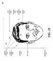
- FIG. 18 depicts example results of two k-means analyses, in accordance with an embodiment.
- FIG. 18 depicts a graphical overview 1800 that includes a line segment 1802 , a first set of final mean colors 1822 resulting from a first k-means analysis, and a second set of final mean colors 1832 resulting from a second k-means analysis.
- the line segment 1802 includes pixels 1804 - 1820 , each of the pixels 1804 - 1820 being a respective color.
- the first set of final mean colors 1822 includes a final mean color 1824 , a final mean color 1826 , and a final mean color 1828 .
- the final mean color 1824 is derived from a configuration-independent initial mean that is representative of a color of a background.
- the final mean color 1826 is derived from a configuration-dependent initial mean that is representative of a color of hair of a user.
- the final mean color 1828 is derived from a configuration-independent initial mean that is representative of a color of a face of the user.
- the second set of final mean colors 1832 includes a final mean color 1834 , a final mean color 1836 , and a final mean color 1838 .
- the final mean color 1834 is derived from a configuration-independent initial mean that is representative of a color of a background.
- the pixels 1804 - 1820 are broken up into clusters.
- Each k-means analysis groups the pixels 1804 - 1820 of the line segment 1802 into three clusters, wherein each cluster corresponds with one of the final mean colors resulting from a k-means clustering of the line segment 1802 .
- the first k-means analysis produces the final mean color 1824 which is an average color of the respective colors of the pixels 1804 - 1808 .
- the final mean color 1824 may be used to update a background-color model.
- the pixels 1804 - 1808 may be used to update a background-color model.
- the first k-means analysis also produces the final mean color 1826 which is an average color of the respective colors of the pixels 1810 - 1816 .
- the first k-means analysis produces the final mean color 1828 which is an average color of the respective colors of the pixels 1818 - 1820 .
- using the final mean colors derived from the configuration-dependent initial mean colors (i.e., the final mean colors 1828 and 1836 ) to identify the respective set of hair-color pixels from the pixels in the line segment 1802 includes, for each line segment in the set of line segments, (i) selecting each pixel in the line segment that has a color closer to the final mean color that was derived from the configuration-dependent initial mean color (i.e., the final mean colors 1828 and 1836 ) than to either of the other two final mean colors (i.e, the final mean colors 1824 , 1828 , 1834 , and 1838 ), and (ii) identifying the respective set of hair-color pixels as the selected pixels.
- the graphic overview 1800 is a simple example, as the set of line segments includes only one line segment, the line segment 1802 .
- each line segment in the set of line segments will be associated with its own sets of final mean colors (one set of final mean colors per line segment per k-means analysis).
- the results of various k-means analyses are compared.
- a number of continuous pixels each having a color that is closer to the final mean color associated with the configuration-dependent initial mean color than to either of the other two final mean colors, is compared between each of the various k-means analyses.
- a preferred k-means analysis is determined to be whichever k-means analysis employed the initial configuration that produced the largest number of continuous pixels.
- selecting one of the identified sets of hair-color pixels based on one or more hair-color-pixel-set criteria includes selecting whichever identified set of hair-color pixels is associated with the k-means analysis that produced the largest tally/count.
- selecting hair-color pixels may include selecting a subset of pixels from the selected identified set. At least one embodiment comprises selecting only pixels from line segments that prefer the k-means analysis which produced the largest tally/count. In at least one embodiment, using the final mean colors (i.e., the final mean colors 1828 and 1836 ) derived from the configuration-dependent initial mean colors to identify the respective set of hair-color pixels from the pixels in the line segment 1802 includes, for each line segment in the set of line segments, (i) selecting a longest continuous group of pixels in the line segment.
- each pixel in the group has a color that is closer to the final mean color (i.e., the final mean colors 1826 and 1836 ) that was derived from the configuration-dependent initial mean color than to either of the other two final mean colors (i.e, the final mean colors 1824 , 1828 , 1834 , and 1838 ), and (ii) identifying the respective set of hair-color pixels as the pixels in the longest continuous groups (i.e., the pixels 1810 - 1816 for the first k-means analysis and the pixels 1814 - 1818 for the second k-means analysis).
- the preferred analysis may be determined as follows.
- a number of continuous pixels, each having a color that is closer to the final mean color associated with the configuration-dependent initial mean color than to either of the other two final mean colors is compared against a threshold length.
- Each line segment, wherein the number of continuous pixels having a color that is closer to the final mean color associated with the configuration-dependent initial mean color than to either of the other two final mean colors is greater in length than the threshold length is counted as valid.
- a respective tally/count of valid line segments for each k-means analysis is maintained (i.e., each k-means analysis has a corresponding tally/count of valid line segments).
- the preferred k-means analysis is the analysis which produced the largest count of valid line segments. Many other techniques for determining line segment validity may be employed as well, many of which are discussed herein.
- selecting one of the identified sets of hair-color pixels based on one or more hair-color-pixel-set criteria includes selecting whichever identified set of hair-color pixels is associated with the k-means analysis that produced the largest tally/count of valid line segments.
- selecting one of the identified sets of hair-color pixels includes selecting whichever identified set of hair-color pixels is larger.
- the identified set of hair pixels associated with the final mean color 1826 is larger as it includes four pixels and the identified set of hair pixels associated with the final mean 1836 only includes three pixels.
- each pixel in the group has a color that is closer to the final mean color (i.e., the final mean colors 1826 and 1836 ) that was derived from the configuration-dependent initial mean color than to either of the other two final mean colors (i.e, the final mean colors 1824 , 1828 , 1834 , and 1838 ), (ii) selecting the longest continuous groups that exceed a threshold length, and (iii) identifying the respective set of hair-color pixels as the pixels in the selected longest continuous groups.
- the final mean color i.e., the final mean colors 1826 and 1836
- an individual hair-color pixel or set of hair-color pixels is disregarded because it is not within a threshold tolerance of being hair according to an existing user-hair-color model. In at least one embodiment, an individual hair-color pixel or set of hair-color pixels is disregarded because it is within a threshold tolerance of being background according to an existing background-color model.
- FIG. 19 depicts a generation of a user-hair-color model, in accordance with an embodiment.
- FIG. 19 depicts a graphical overview 1900 that includes a selected set of hair-color pixels 1902 and a user-hair-color model 1904 .
- using the selected set of hair-color pixels 1902 to generate the user-hair-color model 1904 includes, for each pixel in the selected set of hair-color pixels 1902 , adding a singular user-hair-color-model entry corresponding to a color of the pixel.
- using the selected set of hair-color pixels 1902 to generate the user-hair-color model 1904 includes, for each pixel in the selected set of hair-color pixels 1902 , adding a plurality of user-hair-color-model entries corresponding to a color of the pixel as well as colors that are close to the color of the pixel. This technique is known as padding and is well understood by those with skill in the relevant art.
- FIG. 20 depicts an example computing and communication device (CCD), in accordance with an embodiment.
- an example CCD 2000 includes a communication interface 2002 , a processor 2004 , and data storage 2006 containing instructions 2008 executable by the processor 2004 for causing the CCD 2000 to carry out a set of functions, which may include those functions described above in connection with FIG. 1A and/or FIG. 1B .
- the example CCD 2000 is presented as an example system that could be programmed and configured to carry out the functions described herein.
- the data storage 2006 may take the form of any non-transitory computer-readable medium or combination of such media, some examples including flash memory, read-only memory (ROM), and random-access memory (RAM) to name but a few, as any one or more types of non-transitory data-storage technology deemed suitable by those of skill in the relevant art could be used.
- the data storage 2006 contains program instructions 2008 executable by the processor 2004 for carrying out various functions, and also contains operational data 2010 , which could include any one or more types of data stored and/or accessed by the example CCD 2000 during operation.
- a computing system such as the example CCD 2000 is arranged, programmed, and configured to carry out processes such as the example process that is described above in connection with FIG.
- the program instructions 2008 are executable by the processor 2004 for carrying out those functions; in instances where other entities described herein have a structure similar to that of the example CCD 2000 , the respective program instructions 2008 for those respective devices are executable by their respective processors 2004 to carry out functions respectively performed by those devices.
- the user interface 2012 may include one or more input devices (a.k.a. components and the like) and/or one or more output devices (a.k.a. components and the like).
- the user interface 2012 may include one or more touchscreens, buttons, switches, microphones, and the like.
- the user interface 2012 may include one or more displays, speakers, light emitting diodes (LEDs), and the like.
- one or more components e.g., an interactive touchscreen-and-display component
- the CCD 2000 may include one or more video cameras, depth cameras, 3-D cameras, infrared-visible cameras, light-field cameras or a combination thereof.
- processors such as microprocessors, digital signal processors, customized processors and field programmable gate arrays (FPGAs) and unique stored program instructions (including both software and firmware) that control the one or more processors to implement, in conjunction with certain non-processor circuits, some, most, or all of the functions of the method and/or apparatus described herein.
- processors or “processing devices” such as microprocessors, digital signal processors, customized processors and field programmable gate arrays (FPGAs) and unique stored program instructions (including both software and firmware) that control the one or more processors to implement, in conjunction with certain non-processor circuits, some, most, or all of the functions of the method and/or apparatus described herein.
- FPGAs field programmable gate arrays
- unique stored program instructions including both software and firmware
Abstract
Description
Claims (20)
Priority Applications (1)
| Application Number | Priority Date | Filing Date | Title |
|---|---|---|---|
| US14/842,525 US9607397B2 (en) | 2015-09-01 | 2015-09-01 | Methods and systems for generating a user-hair-color model |
Applications Claiming Priority (1)
| Application Number | Priority Date | Filing Date | Title |
|---|---|---|---|
| US14/842,525 US9607397B2 (en) | 2015-09-01 | 2015-09-01 | Methods and systems for generating a user-hair-color model |
Publications (2)
| Publication Number | Publication Date |
|---|---|
| US20170061640A1 US20170061640A1 (en) | 2017-03-02 |
| US9607397B2 true US9607397B2 (en) | 2017-03-28 |
Family
ID=58104077
Family Applications (1)
| Application Number | Title | Priority Date | Filing Date |
|---|---|---|---|
| US14/842,525 Active US9607397B2 (en) | 2015-09-01 | 2015-09-01 | Methods and systems for generating a user-hair-color model |
Country Status (1)
| Country | Link |
|---|---|
| US (1) | US9607397B2 (en) |
Cited By (3)
| Publication number | Priority date | Publication date | Assignee | Title |
|---|---|---|---|---|
| US10948351B2 (en) * | 2016-11-11 | 2021-03-16 | Henkel Ag & Co. Kgaa | Method and device for determining the color homogeneity of hair |
| US10984589B2 (en) | 2017-08-07 | 2021-04-20 | Verizon Patent And Licensing Inc. | Systems and methods for reference-model-based modification of a three-dimensional (3D) mesh data model |
| US11095854B2 (en) | 2017-08-07 | 2021-08-17 | Verizon Patent And Licensing Inc. | Viewpoint-adaptive three-dimensional (3D) personas |
Families Citing this family (2)
| Publication number | Priority date | Publication date | Assignee | Title |
|---|---|---|---|---|
| DE102017211599A1 (en) * | 2017-07-07 | 2019-01-10 | Henkel Ag & Co. Kgaa | Method and device for computer-assisted determination of a hair dyeing result |
| CN107588511A (en) * | 2017-09-21 | 2018-01-16 | 四川长虹电器股份有限公司 | Air conditioner energy source management system and method based on contour and HOG human testings |
Citations (60)
| Publication number | Priority date | Publication date | Assignee | Title |
|---|---|---|---|---|
| US5001558A (en) | 1985-06-11 | 1991-03-19 | General Motors Corporation | Night vision system with color video camera |
| US5022085A (en) | 1990-05-29 | 1991-06-04 | Eastman Kodak Company | Neighborhood-based merging of image data |
| US5117283A (en) | 1990-06-25 | 1992-05-26 | Eastman Kodak Company | Photobooth compositing apparatus |
| US5227985A (en) | 1991-08-19 | 1993-07-13 | University Of Maryland | Computer vision system for position monitoring in three dimensions using non-coplanar light sources attached to a monitored object |
| US5343311A (en) | 1992-04-14 | 1994-08-30 | Electronics For Imaging, Inc. | Indexed processing of color image data |
| US5506946A (en) | 1991-10-01 | 1996-04-09 | Electronics For Imaging, Inc. | Selective color correction |
| US5534917A (en) | 1991-05-09 | 1996-07-09 | Very Vivid, Inc. | Video image based control system |
| US5581276A (en) | 1992-09-08 | 1996-12-03 | Kabushiki Kaisha Toshiba | 3D human interface apparatus using motion recognition based on dynamic image processing |
| US5631697A (en) | 1991-11-27 | 1997-05-20 | Hitachi, Ltd. | Video camera capable of automatic target tracking |
| US5687306A (en) | 1992-02-25 | 1997-11-11 | Image Ware Software, Inc. | Image editing system including sizing function |
| US6150930A (en) | 1992-08-14 | 2000-11-21 | Texas Instruments Incorporated | Video equipment and method to assist motor vehicle operators |
| US20020051491A1 (en) | 1998-11-20 | 2002-05-02 | Kiran Challapali | Extraction of foreground information for video conference |
| US6411744B1 (en) | 1997-10-15 | 2002-06-25 | Electric Planet, Inc. | Method and apparatus for performing a clean background subtraction |
| US20020158873A1 (en) | 2001-01-26 | 2002-10-31 | Todd Williamson | Real-time virtual viewpoint in simulated reality environment |
| US6661918B1 (en) | 1998-12-04 | 2003-12-09 | Interval Research Corporation | Background estimation and segmentation based on range and color |
| US6664973B1 (en) | 1996-04-28 | 2003-12-16 | Fujitsu Limited | Image processing apparatus, method for processing and image and computer-readable recording medium for causing a computer to process images |
| US20040153671A1 (en) | 2002-07-29 | 2004-08-05 | Schuyler Marc P. | Automated physical access control systems and methods |
| US20050094879A1 (en) | 2003-10-31 | 2005-05-05 | Michael Harville | Method for visual-based recognition of an object |
| US20050219264A1 (en) | 2004-04-01 | 2005-10-06 | Microsoft Corporation | Pop-up light field |
| US20060072022A1 (en) | 2004-10-06 | 2006-04-06 | Yoshiaki Iwai | Image processing method and image processing device |
| US20060193509A1 (en) | 2005-02-25 | 2006-08-31 | Microsoft Corporation | Stereo-based image processing |
| US20070036432A1 (en) | 2003-11-12 | 2007-02-15 | Li-Qun Xu | Object detection in images |
| US20070110298A1 (en) | 2005-11-14 | 2007-05-17 | Microsoft Corporation | Stereo video for gaming |
| US20070146512A1 (en) | 2005-12-27 | 2007-06-28 | Sanyo Electric Co., Ltd. | Imaging apparatus provided with imaging device having sensitivity in visible and infrared regions |
| US20070201738A1 (en) | 2005-07-21 | 2007-08-30 | Atsushi Toda | Physical information acquisition method, physical information acquisition device, and semiconductor device |
| US20080181507A1 (en) | 2007-01-29 | 2008-07-31 | Intellivision Technologies Corp. | Image manipulation for videos and still images |
| US20080273751A1 (en) | 2006-10-16 | 2008-11-06 | Chang Yuan | Detection and Tracking of Moving Objects from a Moving Platform in Presence of Strong Parallax |
| US20090003687A1 (en) | 2006-01-10 | 2009-01-01 | Microsoft Corporation | Segmenting Image Elements |
| US20090110299A1 (en) | 2007-10-30 | 2009-04-30 | Kddi Corporation | Apparatus, method and computer program for classifying pixels in a motion picture as foreground or background |
| US7574043B2 (en) | 2005-06-27 | 2009-08-11 | Mitsubishi Electric Research Laboratories, Inc. | Method for modeling cast shadows in videos |
| US20090245571A1 (en) | 2008-03-31 | 2009-10-01 | National Taiwan University | Digital video target moving object segmentation method and system |
| US20090244309A1 (en) | 2006-08-03 | 2009-10-01 | Benoit Maison | Method and Device for Identifying and Extracting Images of multiple Users, and for Recognizing User Gestures |
| US20090284627A1 (en) | 2008-05-16 | 2009-11-19 | Kaibushiki Kaisha Toshiba | Image processing Method |
| US20100046830A1 (en) | 2008-08-22 | 2010-02-25 | Jue Wang | Automatic Video Image Segmentation |
| US20100053212A1 (en) | 2006-11-14 | 2010-03-04 | Mi-Sun Kang | Portable device having image overlay function and method of overlaying image in portable device |
| US20100128927A1 (en) | 2008-03-14 | 2010-05-27 | Sony Computer Entertainment Inc. | Image processing apparatus and image processing method |
| US20100195898A1 (en) | 2009-01-28 | 2010-08-05 | Electronics And Telecommunications Research Institute | Method and apparatus for improving quality of depth image |
| US7773136B2 (en) | 2006-08-28 | 2010-08-10 | Sanyo Electric Co., Ltd. | Image pickup apparatus and image pickup method for equalizing infrared components in each color component signal |
| US20100302395A1 (en) | 2009-05-29 | 2010-12-02 | Microsoft Corporation | Environment And/Or Target Segmentation |
| US20110038536A1 (en) | 2009-08-14 | 2011-02-17 | Genesis Group Inc. | Real-time image and video matting |
| US20110115886A1 (en) | 2009-11-18 | 2011-05-19 | The Board Of Trustees Of The University Of Illinois | System for executing 3d propagation for depth image-based rendering |
| US20110193939A1 (en) | 2010-02-09 | 2011-08-11 | Microsoft Corporation | Physical interaction zone for gesture-based user interfaces |
| US20110243430A1 (en) | 2008-11-04 | 2011-10-06 | Konica Minolta Opto, Inc. | Image input apparatus |
| US20110249883A1 (en) | 2010-04-09 | 2011-10-13 | General Electric Company | Methods for segmenting objects in images |
| US20110293179A1 (en) | 2010-05-31 | 2011-12-01 | Mert Dikmen | Systems and methods for illumination correction of an image |
| US20120051631A1 (en) | 2010-08-30 | 2012-03-01 | The Board Of Trustees Of The University Of Illinois | System for background subtraction with 3d camera |
| US8175384B1 (en) | 2008-03-17 | 2012-05-08 | Adobe Systems Incorporated | Method and apparatus for discriminative alpha matting |
| US8300890B1 (en) | 2007-01-29 | 2012-10-30 | Intellivision Technologies Corporation | Person/object image and screening |
| US20130016097A1 (en) | 2010-04-02 | 2013-01-17 | Imec | Virtual Camera System |
| US20130028476A1 (en) | 2009-01-30 | 2013-01-31 | Microsoft Corporation | Pose tracking pipeline |
| US8396328B2 (en) | 2001-05-04 | 2013-03-12 | Legend3D, Inc. | Minimal artifact image sequence depth enhancement system and method |
| US20130094780A1 (en) | 2010-06-01 | 2013-04-18 | Hewlett-Packard Development Company, L.P. | Replacement of a Person or Object in an Image |
| US20130142452A1 (en) | 2011-12-02 | 2013-06-06 | Sony Corporation | Image processing device and image processing method |
| US20130243313A1 (en) | 2010-10-01 | 2013-09-19 | Telefonica, S.A. | Method and system for images foreground segmentation in real-time |
| US20140029788A1 (en) | 2012-07-26 | 2014-01-30 | Jinman Kang | Detecting objects with a depth sensor |
| US8649932B2 (en) | 2006-10-27 | 2014-02-11 | International Electronic Machines Corp. | Vehicle evaluation using infrared data |
| US20140153784A1 (en) | 2012-10-18 | 2014-06-05 | Thomson Licensing | Spatio-temporal confidence maps |
| US20140307056A1 (en) | 2013-04-15 | 2014-10-16 | Microsoft Corporation | Multimodal Foreground Background Segmentation |
| US8884980B2 (en) * | 2010-09-24 | 2014-11-11 | Taaz, Inc. | System and method for changing hair color in digital images |
| US20150187076A1 (en) * | 2013-12-31 | 2015-07-02 | Personify, Inc. | System and Methods for Persona Identification Using Combined Probability Maps |
-
2015
- 2015-09-01 US US14/842,525 patent/US9607397B2/en active Active
Patent Citations (64)
| Publication number | Priority date | Publication date | Assignee | Title |
|---|---|---|---|---|
| US5001558A (en) | 1985-06-11 | 1991-03-19 | General Motors Corporation | Night vision system with color video camera |
| US5022085A (en) | 1990-05-29 | 1991-06-04 | Eastman Kodak Company | Neighborhood-based merging of image data |
| US5117283A (en) | 1990-06-25 | 1992-05-26 | Eastman Kodak Company | Photobooth compositing apparatus |
| US5534917A (en) | 1991-05-09 | 1996-07-09 | Very Vivid, Inc. | Video image based control system |
| US5227985A (en) | 1991-08-19 | 1993-07-13 | University Of Maryland | Computer vision system for position monitoring in three dimensions using non-coplanar light sources attached to a monitored object |
| US5506946A (en) | 1991-10-01 | 1996-04-09 | Electronics For Imaging, Inc. | Selective color correction |
| US5631697A (en) | 1991-11-27 | 1997-05-20 | Hitachi, Ltd. | Video camera capable of automatic target tracking |
| US5687306A (en) | 1992-02-25 | 1997-11-11 | Image Ware Software, Inc. | Image editing system including sizing function |
| US5343311A (en) | 1992-04-14 | 1994-08-30 | Electronics For Imaging, Inc. | Indexed processing of color image data |
| US5517334A (en) | 1992-04-14 | 1996-05-14 | Electronics For Imaging, Inc. | Indexed processing of color image data |
| US6150930A (en) | 1992-08-14 | 2000-11-21 | Texas Instruments Incorporated | Video equipment and method to assist motor vehicle operators |
| US5581276A (en) | 1992-09-08 | 1996-12-03 | Kabushiki Kaisha Toshiba | 3D human interface apparatus using motion recognition based on dynamic image processing |
| US6664973B1 (en) | 1996-04-28 | 2003-12-16 | Fujitsu Limited | Image processing apparatus, method for processing and image and computer-readable recording medium for causing a computer to process images |
| US6411744B1 (en) | 1997-10-15 | 2002-06-25 | Electric Planet, Inc. | Method and apparatus for performing a clean background subtraction |
| US20020051491A1 (en) | 1998-11-20 | 2002-05-02 | Kiran Challapali | Extraction of foreground information for video conference |
| US7317830B1 (en) | 1998-12-04 | 2008-01-08 | Vulcan Patents Llc | Background estimation and segmentation based on range and color |
| US6661918B1 (en) | 1998-12-04 | 2003-12-09 | Interval Research Corporation | Background estimation and segmentation based on range and color |
| US20020158873A1 (en) | 2001-01-26 | 2002-10-31 | Todd Williamson | Real-time virtual viewpoint in simulated reality environment |
| US8396328B2 (en) | 2001-05-04 | 2013-03-12 | Legend3D, Inc. | Minimal artifact image sequence depth enhancement system and method |
| US20040153671A1 (en) | 2002-07-29 | 2004-08-05 | Schuyler Marc P. | Automated physical access control systems and methods |
| US20050094879A1 (en) | 2003-10-31 | 2005-05-05 | Michael Harville | Method for visual-based recognition of an object |
| US20070036432A1 (en) | 2003-11-12 | 2007-02-15 | Li-Qun Xu | Object detection in images |
| US20050219264A1 (en) | 2004-04-01 | 2005-10-06 | Microsoft Corporation | Pop-up light field |
| US7633511B2 (en) | 2004-04-01 | 2009-12-15 | Microsoft Corporation | Pop-up light field |
| US20060072022A1 (en) | 2004-10-06 | 2006-04-06 | Yoshiaki Iwai | Image processing method and image processing device |
| US20060193509A1 (en) | 2005-02-25 | 2006-08-31 | Microsoft Corporation | Stereo-based image processing |
| US7574043B2 (en) | 2005-06-27 | 2009-08-11 | Mitsubishi Electric Research Laboratories, Inc. | Method for modeling cast shadows in videos |
| US20070201738A1 (en) | 2005-07-21 | 2007-08-30 | Atsushi Toda | Physical information acquisition method, physical information acquisition device, and semiconductor device |
| US20070110298A1 (en) | 2005-11-14 | 2007-05-17 | Microsoft Corporation | Stereo video for gaming |
| US20070146512A1 (en) | 2005-12-27 | 2007-06-28 | Sanyo Electric Co., Ltd. | Imaging apparatus provided with imaging device having sensitivity in visible and infrared regions |
| US20090003687A1 (en) | 2006-01-10 | 2009-01-01 | Microsoft Corporation | Segmenting Image Elements |
| US20090244309A1 (en) | 2006-08-03 | 2009-10-01 | Benoit Maison | Method and Device for Identifying and Extracting Images of multiple Users, and for Recognizing User Gestures |
| US7773136B2 (en) | 2006-08-28 | 2010-08-10 | Sanyo Electric Co., Ltd. | Image pickup apparatus and image pickup method for equalizing infrared components in each color component signal |
| US20080273751A1 (en) | 2006-10-16 | 2008-11-06 | Chang Yuan | Detection and Tracking of Moving Objects from a Moving Platform in Presence of Strong Parallax |
| US8649932B2 (en) | 2006-10-27 | 2014-02-11 | International Electronic Machines Corp. | Vehicle evaluation using infrared data |
| US20100053212A1 (en) | 2006-11-14 | 2010-03-04 | Mi-Sun Kang | Portable device having image overlay function and method of overlaying image in portable device |
| US20080181507A1 (en) | 2007-01-29 | 2008-07-31 | Intellivision Technologies Corp. | Image manipulation for videos and still images |
| US8300890B1 (en) | 2007-01-29 | 2012-10-30 | Intellivision Technologies Corporation | Person/object image and screening |
| US20090110299A1 (en) | 2007-10-30 | 2009-04-30 | Kddi Corporation | Apparatus, method and computer program for classifying pixels in a motion picture as foreground or background |
| US20100128927A1 (en) | 2008-03-14 | 2010-05-27 | Sony Computer Entertainment Inc. | Image processing apparatus and image processing method |
| US8175384B1 (en) | 2008-03-17 | 2012-05-08 | Adobe Systems Incorporated | Method and apparatus for discriminative alpha matting |
| US20090245571A1 (en) | 2008-03-31 | 2009-10-01 | National Taiwan University | Digital video target moving object segmentation method and system |
| US20090284627A1 (en) | 2008-05-16 | 2009-11-19 | Kaibushiki Kaisha Toshiba | Image processing Method |
| US20100046830A1 (en) | 2008-08-22 | 2010-02-25 | Jue Wang | Automatic Video Image Segmentation |
| US20110243430A1 (en) | 2008-11-04 | 2011-10-06 | Konica Minolta Opto, Inc. | Image input apparatus |
| US20100195898A1 (en) | 2009-01-28 | 2010-08-05 | Electronics And Telecommunications Research Institute | Method and apparatus for improving quality of depth image |
| US20130028476A1 (en) | 2009-01-30 | 2013-01-31 | Microsoft Corporation | Pose tracking pipeline |
| US20100302395A1 (en) | 2009-05-29 | 2010-12-02 | Microsoft Corporation | Environment And/Or Target Segmentation |
| US8320666B2 (en) | 2009-08-14 | 2012-11-27 | Genesis Group Inc. | Real-time image and video matting |
| US20110038536A1 (en) | 2009-08-14 | 2011-02-17 | Genesis Group Inc. | Real-time image and video matting |
| US20110115886A1 (en) | 2009-11-18 | 2011-05-19 | The Board Of Trustees Of The University Of Illinois | System for executing 3d propagation for depth image-based rendering |
| US20110193939A1 (en) | 2010-02-09 | 2011-08-11 | Microsoft Corporation | Physical interaction zone for gesture-based user interfaces |
| US20130016097A1 (en) | 2010-04-02 | 2013-01-17 | Imec | Virtual Camera System |
| US20110249883A1 (en) | 2010-04-09 | 2011-10-13 | General Electric Company | Methods for segmenting objects in images |
| US20110293179A1 (en) | 2010-05-31 | 2011-12-01 | Mert Dikmen | Systems and methods for illumination correction of an image |
| US20130094780A1 (en) | 2010-06-01 | 2013-04-18 | Hewlett-Packard Development Company, L.P. | Replacement of a Person or Object in an Image |
| US20120051631A1 (en) | 2010-08-30 | 2012-03-01 | The Board Of Trustees Of The University Of Illinois | System for background subtraction with 3d camera |
| US8884980B2 (en) * | 2010-09-24 | 2014-11-11 | Taaz, Inc. | System and method for changing hair color in digital images |
| US20130243313A1 (en) | 2010-10-01 | 2013-09-19 | Telefonica, S.A. | Method and system for images foreground segmentation in real-time |
| US20130142452A1 (en) | 2011-12-02 | 2013-06-06 | Sony Corporation | Image processing device and image processing method |
| US20140029788A1 (en) | 2012-07-26 | 2014-01-30 | Jinman Kang | Detecting objects with a depth sensor |
| US20140153784A1 (en) | 2012-10-18 | 2014-06-05 | Thomson Licensing | Spatio-temporal confidence maps |
| US20140307056A1 (en) | 2013-04-15 | 2014-10-16 | Microsoft Corporation | Multimodal Foreground Background Segmentation |
| US20150187076A1 (en) * | 2013-12-31 | 2015-07-02 | Personify, Inc. | System and Methods for Persona Identification Using Combined Probability Maps |
Non-Patent Citations (13)
| Title |
|---|
| Arbelaez, P., et al., "Contour detection and hierarchical image segmentation", Pattern Analysis and Machine Intelligence, IEEE Transactions on 33.5 (2011): 898-916. (The year of publication is sufficiently earlier than the affective U.S. filing date and any foreign priority date so that the particular month of publication is not an issue.). |
| Benezeth et al., "Review and Evaluation of Commonly-Implemented Background Subtraction Algorithms", 2008. (The year of publication is sufficiently earlier than the effective U.S. filing date and any foreign priority date so that the particular month of publication is not an issue.). |
| Cheung et al., "Robust Techniques for Background Subtraction in Urban Traffic Video", 2004. (The year of publication is sufficiently earlier than the effective U.S. filing date and any foreign priority date so that the particular month of publication is not an issue.). |
| Crabb et al., "Real-Time Foreground Segmentation via Range and Color Imaging", 2008. (The year of publication is sufficiently earlier than the effective U.S. filing date and any foreign priority date so that the particular maonth of publication is not an issue.). |
| Gvili et al., "Depth Keying", 2003. (The year of publication is sufficiently earlier than the effective U.S. filing date and any foreign priority date so that the particular month of publication is not an issue.). |
| Izquierdo, M. Ebroul, "Disparity/segmentation analysis: matching with an adaptive window and depth-driven segmentation", Circuits and Systems for Video Technology, IEEE Transactions on 9.4 (1999): 589-607. (The year of publication is sufficiently earlier than the effective U.S. filing date and any foreign priority date so that the particular month of publication is not an issue.). |
| Kolmogorov et al., "Bi-Layer Segmentation of Binocular Stereo Vision", IEEE, 2005. (the year of publication is sufficiently earlier than the effective U.S. filing date and any foreign priority date so that the particular month of publication is not an issue.). |
| Lee, D.S., "Effective Gaussian Mixture Learning for Video Background Subtraction", IEEE, May 2005. (The year of 3ublic.ation is sufficiently earlier than the effective U.S. filing date and any foreign priority date so that the particular month of publication is not an issue.). |
| Piccardi, M., "Background Subtraction Techniques: A Review", IEEE, 2004. (The year of publication is sufficiently earlier than the effective U.S. filing date and any foreign priority date so that the particular month of publication is not an issue.). |
| Rother, C., et al., "Grabut: Interactive Foreground extraction using iterated graph cuts", ACM Transactions on Graphics (TOG)23.3 (2004): 309-314. (The year of publication is sufficiently earlier than the effective U.S. filing date and any foreign priority date so that the particular month of publication is not an issue.). |
| Wang, L., et al., "Tofcut: Towards robust real-time foreground extraction using a time-of-flight camera." Proc. of BDPVT 2010. (The year of publication in sufficiently earlier than the effective U.S. filig date and any foreign priority date so that the particular month of publication is not an issue.). |
| Xu, F. et al., "Human detection using depth and gray images", Advanced Video and Signal Based Surveillance, 2003, Proceedings IEEE Conference. (The year of publication is sufficiently earlier that the effective U.S. filing date and any foreign priority date so that the particular month of publication is not an issue.). |
| Zhang, Q., et al., "Segmentation and tracking multiple objects under occlusion from multiview video", Image Processing, IEEE Transactions on 20.11 (2011): 3308-3313. (The year of publication is sufficiently earlier than the affective U.S. filing date and any foreign priority date so that the particular month of publication is not an issue.). |
Cited By (9)
| Publication number | Priority date | Publication date | Assignee | Title |
|---|---|---|---|---|
| US10948351B2 (en) * | 2016-11-11 | 2021-03-16 | Henkel Ag & Co. Kgaa | Method and device for determining the color homogeneity of hair |
| US10984589B2 (en) | 2017-08-07 | 2021-04-20 | Verizon Patent And Licensing Inc. | Systems and methods for reference-model-based modification of a three-dimensional (3D) mesh data model |
| US10997786B2 (en) | 2017-08-07 | 2021-05-04 | Verizon Patent And Licensing Inc. | Systems and methods for reconstruction and rendering of viewpoint-adaptive three-dimensional (3D) personas |
| US11004264B2 (en) | 2017-08-07 | 2021-05-11 | Verizon Patent And Licensing Inc. | Systems and methods for capturing, transferring, and rendering viewpoint-adaptive three-dimensional (3D) personas |
| US11024078B2 (en) | 2017-08-07 | 2021-06-01 | Verizon Patent And Licensing Inc. | Systems and methods compression, transfer, and reconstruction of three-dimensional (3D) data meshes |
| US11095854B2 (en) | 2017-08-07 | 2021-08-17 | Verizon Patent And Licensing Inc. | Viewpoint-adaptive three-dimensional (3D) personas |
| US11386618B2 (en) | 2017-08-07 | 2022-07-12 | Verizon Patent And Licensing Inc. | Systems and methods for model-based modification of a three-dimensional (3D) mesh |
| US11461969B2 (en) | 2017-08-07 | 2022-10-04 | Verizon Patent And Licensing Inc. | Systems and methods compression, transfer, and reconstruction of three-dimensional (3D) data meshes |
| US11580697B2 (en) | 2017-08-07 | 2023-02-14 | Verizon Patent And Licensing Inc. | Systems and methods for reconstruction and rendering of viewpoint-adaptive three-dimensional (3D) personas |
Also Published As
| Publication number | Publication date |
|---|---|
| US20170061640A1 (en) | 2017-03-02 |
Similar Documents
| Publication | Publication Date | Title |
|---|---|---|
| US9953223B2 (en) | Methods and systems for assigning pixels distance-cost values using a flood fill technique | |
| US9607397B2 (en) | Methods and systems for generating a user-hair-color model | |
| US10491895B2 (en) | Fast and robust human skin tone region detection for improved video coding | |
| US10628700B2 (en) | Fast and robust face detection, region extraction, and tracking for improved video coding | |
| US11620739B2 (en) | Image generation device, image generation method, and storage medium storing program | |
| US9384386B2 (en) | Methods and systems for increasing facial recognition working rang through adaptive super-resolution | |
| US8983152B2 (en) | Image masks for face-related selection and processing in images | |
| US10204432B2 (en) | Methods and systems for color processing of digital images | |
| WO2017092431A1 (en) | Human hand detection method and device based on skin colour | |
| US10430694B2 (en) | Fast and accurate skin detection using online discriminative modeling | |
| JP7063039B2 (en) | Target detection method, target detection device and image processing device | |
| US20160092726A1 (en) | Using gestures to train hand detection in ego-centric video | |
| US10438376B2 (en) | Image processing apparatus replacing color of portion in image into single color, image processing method, and storage medium | |
| WO2023045183A1 (en) | Image processing | |
| US10244224B2 (en) | Methods and systems for classifying pixels as foreground using both short-range depth data and long-range depth data | |
| CN112686965A (en) | Skin color detection method, device, mobile terminal and storage medium | |
| US20160343148A1 (en) | Methods and systems for identifying background in video data using geometric primitives | |
| WO2015189369A1 (en) | Methods and systems for color processing of digital images | |
| US9646386B2 (en) | Method and apparatus for generating temporally consistent superpixels | |
| US9390481B2 (en) | Enhancing content appearance | |
| US20170372495A1 (en) | Methods and systems for color processing of digital images | |
| US9251567B1 (en) | Providing color corrections to photos | |
| Juneja et al. | A hybrid mathematical model for face localization over multi-person images and videos | |
| CN112750151B (en) | Clothing color matching method, device and equipment based on mathematical statistics | |
| Cha et al. | Performance Analysis of Face Detection Algorithms for Efficient Comparison of Predection Time and Accuracy |
Legal Events
| Date | Code | Title | Description |
|---|---|---|---|
| AS | Assignment |
Owner name: PERSONIFY, INC., ILLINOIS Free format text: ASSIGNMENT OF ASSIGNORS INTEREST;ASSIGNORS:LIN, DENNIS;FRANCISCO, GLENN;DANG, GIA;AND OTHERS;SIGNING DATES FROM 20150904 TO 20150907;REEL/FRAME:037778/0021 |
|
| AS | Assignment |
Owner name: PERSONIFY, INC., ILLINOIS Free format text: CORRECTIVE ASSIGNMENT TO CORRECT THE SPELLING OF THE FOURTH ASSIGNOR'S NAME PREVIOUSLY RECORDED ON REEL 037778 FRAME 0021. ASSIGNOR(S) HEREBY CONFIRMS THE ASSIGNMENT;ASSIGNORS:LIN, DENNIS;FRANCISCO, GLENN;DA NG, GIA;AND OTHERS;SIGNING DATES FROM 20150904 TO 20150907;REEL/FRAME:038028/0155 |
|
| STCF | Information on status: patent grant |
Free format text: PATENTED CASE |
|
| AS | Assignment |
Owner name: HONGFUJIN PRECISION INDUSTRY (WUHAN) CO. LTD., TEX Free format text: ASSIGNMENT OF ASSIGNORS INTEREST;ASSIGNOR:PERSONIFY, INC.;REEL/FRAME:051367/0920 Effective date: 20190522 |
|
| FEPP | Fee payment procedure |
Free format text: ENTITY STATUS SET TO UNDISCOUNTED (ORIGINAL EVENT CODE: BIG.); ENTITY STATUS OF PATENT OWNER: LARGE ENTITY |
|
| MAFP | Maintenance fee payment |
Free format text: PAYMENT OF MAINTENANCE FEE, 4TH YEAR, LARGE ENTITY (ORIGINAL EVENT CODE: M1551); ENTITY STATUS OF PATENT OWNER: LARGE ENTITY Year of fee payment: 4 |
|
| AS | Assignment |
Owner name: PERSONIFY, INC., CALIFORNIA Free format text: ASSIGNMENT OF ASSIGNORS INTEREST;ASSIGNOR:HONGFUJIN PRECISION INDUSTRY WUHAN;REEL/FRAME:057467/0738 Effective date: 20210909 |