US9660397B2 - Plate for cable connector attachments - Google Patents
Plate for cable connector attachments Download PDFInfo
- Publication number
- US9660397B2 US9660397B2 US14/667,578 US201514667578A US9660397B2 US 9660397 B2 US9660397 B2 US 9660397B2 US 201514667578 A US201514667578 A US 201514667578A US 9660397 B2 US9660397 B2 US 9660397B2
- Authority
- US
- United States
- Prior art keywords
- plate
- connector
- connectors
- nut
- bracket
- Prior art date
- Legal status (The legal status is an assumption and is not a legal conclusion. Google has not performed a legal analysis and makes no representation as to the accuracy of the status listed.)
- Expired - Fee Related
Links
- 239000004020 conductor Substances 0.000 claims description 3
- 239000013307 optical fiber Substances 0.000 claims description 3
- 230000013011 mating Effects 0.000 abstract description 6
- 238000004891 communication Methods 0.000 description 4
- 239000000835 fiber Substances 0.000 description 4
- 238000012986 modification Methods 0.000 description 3
- 230000004048 modification Effects 0.000 description 3
- 239000004593 Epoxy Substances 0.000 description 2
- 230000008901 benefit Effects 0.000 description 2
- 238000000034 method Methods 0.000 description 2
- 230000007704 transition Effects 0.000 description 2
- 239000000853 adhesive Substances 0.000 description 1
- 230000001070 adhesive effect Effects 0.000 description 1
- 238000010276 construction Methods 0.000 description 1
- 238000004519 manufacturing process Methods 0.000 description 1
- 230000008569 process Effects 0.000 description 1
- 230000011664 signaling Effects 0.000 description 1
- XLYOFNOQVPJJNP-UHFFFAOYSA-N water Substances O XLYOFNOQVPJJNP-UHFFFAOYSA-N 0.000 description 1
Images


Classifications
-
- H—ELECTRICITY
- H01—ELECTRIC ELEMENTS
- H01R—ELECTRICALLY-CONDUCTIVE CONNECTIONS; STRUCTURAL ASSOCIATIONS OF A PLURALITY OF MUTUALLY-INSULATED ELECTRICAL CONNECTING ELEMENTS; COUPLING DEVICES; CURRENT COLLECTORS
- H01R13/00—Details of coupling devices of the kinds covered by groups H01R12/70 or H01R24/00 - H01R33/00
- H01R13/73—Means for mounting coupling parts to apparatus or structures, e.g. to a wall
- H01R13/74—Means for mounting coupling parts in openings of a panel
-
- G—PHYSICS
- G02—OPTICS
- G02B—OPTICAL ELEMENTS, SYSTEMS OR APPARATUS
- G02B6/00—Light guides; Structural details of arrangements comprising light guides and other optical elements, e.g. couplings
- G02B6/24—Coupling light guides
- G02B6/36—Mechanical coupling means
- G02B6/38—Mechanical coupling means having fibre to fibre mating means
- G02B6/3807—Dismountable connectors, i.e. comprising plugs
- G02B6/3897—Connectors fixed to housings, casing, frames or circuit boards
-
- G—PHYSICS
- G02—OPTICS
- G02B—OPTICAL ELEMENTS, SYSTEMS OR APPARATUS
- G02B6/00—Light guides; Structural details of arrangements comprising light guides and other optical elements, e.g. couplings
- G02B6/44—Mechanical structures for providing tensile strength and external protection for fibres, e.g. optical transmission cables
- G02B6/4439—Auxiliary devices
- G02B6/444—Systems or boxes with surplus lengths
- G02B6/4452—Distribution frames
-
- H—ELECTRICITY
- H01—ELECTRIC ELEMENTS
- H01R—ELECTRICALLY-CONDUCTIVE CONNECTIONS; STRUCTURAL ASSOCIATIONS OF A PLURALITY OF MUTUALLY-INSULATED ELECTRICAL CONNECTING ELEMENTS; COUPLING DEVICES; CURRENT COLLECTORS
- H01R13/00—Details of coupling devices of the kinds covered by groups H01R12/70 or H01R24/00 - H01R33/00
- H01R13/46—Bases; Cases
- H01R13/516—Means for holding or embracing insulating body, e.g. casing, hoods
- H01R13/518—Means for holding or embracing insulating body, e.g. casing, hoods for holding or embracing several coupling parts, e.g. frames
-
- H—ELECTRICITY
- H01—ELECTRIC ELEMENTS
- H01R—ELECTRICALLY-CONDUCTIVE CONNECTIONS; STRUCTURAL ASSOCIATIONS OF A PLURALITY OF MUTUALLY-INSULATED ELECTRICAL CONNECTING ELEMENTS; COUPLING DEVICES; CURRENT COLLECTORS
- H01R13/00—Details of coupling devices of the kinds covered by groups H01R12/70 or H01R24/00 - H01R33/00
- H01R13/64—Means for preventing incorrect coupling
- H01R13/645—Means for preventing incorrect coupling by exchangeable elements on case or base
-
- F—MECHANICAL ENGINEERING; LIGHTING; HEATING; WEAPONS; BLASTING
- F16—ENGINEERING ELEMENTS AND UNITS; GENERAL MEASURES FOR PRODUCING AND MAINTAINING EFFECTIVE FUNCTIONING OF MACHINES OR INSTALLATIONS; THERMAL INSULATION IN GENERAL
- F16B—DEVICES FOR FASTENING OR SECURING CONSTRUCTIONAL ELEMENTS OR MACHINE PARTS TOGETHER, e.g. NAILS, BOLTS, CIRCLIPS, CLAMPS, CLIPS OR WEDGES; JOINTS OR JOINTING
- F16B2200/00—Constructional details of connections not covered for in other groups of this subclass
- F16B2200/99—Fasteners with means for avoiding incorrect assembly or positioning
-
- H—ELECTRICITY
- H01—ELECTRIC ELEMENTS
- H01R—ELECTRICALLY-CONDUCTIVE CONNECTIONS; STRUCTURAL ASSOCIATIONS OF A PLURALITY OF MUTUALLY-INSULATED ELECTRICAL CONNECTING ELEMENTS; COUPLING DEVICES; CURRENT COLLECTORS
- H01R13/00—Details of coupling devices of the kinds covered by groups H01R12/70 or H01R24/00 - H01R33/00
- H01R13/73—Means for mounting coupling parts to apparatus or structures, e.g. to a wall
- H01R13/74—Means for mounting coupling parts in openings of a panel
- H01R13/746—Means for mounting coupling parts in openings of a panel using a screw ring
Definitions
- the present invention relates to a mount system for facilitating ordered mating of plural connectors. More particularly, the present invention relates to a mounting system used to connect jumper cables to trunk cables in an antenna tower environment.
- a box unit for connecting jumper cables to trunk cables is known in the prior art of antenna tower wiring systems.
- connection structure and mounting system which is simpler in design and less costly to manufacture.
- the Applicant has also appreciated a need for a design with an inexpensive keying system to simplify the assembly procedures in the field, making the connection process rather foolproof, such that jumper and trunk cables may only be connected in the proper manner.
- connectors which may benefit from the present invention, are the type of mated connectors which exist between the jumper cables (extending up the antenna structure to the remote radio units) and the trunk cables extending down the tower to ground level equipment of the service provider.
- These connectors may be hybrid connectors (having both fiber and electrical elements).
- each connector may present only fiber connections or only electrical connections. Specific functions, like an alarm function, may be dedicated to its own keyed or non-keyed connector. Connector structures to achieve these and other objects are taught in the present disclosure.
- a mounting system for facilitating ordered mating of plural connectors includes a bracket having at least one feature for securing to a pole or wall.
- a plate is connected to the bracket and includes plural mounting positions.
- Optional grounding and/or surge arrestors may be included.
- each mounting position has an inner perimeter shape different than the inner perimeter shapes of the other mounting positions.
- Each connector of plural first connectors includes a threaded portion holding a first nut with an outer perimeter having a shape being unique, as compared to the first nuts of other first connectors. The outer perimeter of the first nut seats into one, and only one, of the plural mounting positions of the plate.
- a second plate may be mounted to, and spaced from, the first plate.
- the second plate includes plural keyholes which are aligned to the plural mounting positions.
- Each keyhole has an inner perimeter shape matching the inner perimeter shape of the mounting position to which the keyhole is aligned.
- the keyholes only permit a second connector, with a matching key nut, to pass therethrough and mate into the first connector in the aligned mounting position.
- FIG. 1 is a front perspective view of a mounting system for holding connectors, in accordance with a first embodiment of the present invention
- FIG. 2 is a front perspective view of the mounting system of FIG. 2 with connectors mounted thereto;
- FIG. 3 is a front perspective view of a modified mounting system, similar to FIGS. 1-2 , including a grounding region;
- FIG. 4 is a front view of a mounting system for holding connectors, in accordance with a second embodiment of the present invention.
- FIG. 5 is a rear perspective view of the mounting system of FIG. 4 ;
- FIG. 6 is a rear perspective view of a modified mounting system, similar to FIGS. 4-5 , including a surge arrestor, a grounding region, and connectors mounted thereto;
- FIG. 7 is a front perspective view of a female hybrid connector with keying features, in accordance with the present invention.
- FIG. 8 is a front perspective view of a keying nut for use with the connectors with keying features of the present invention.
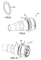
- FIG. 9 is a rear perspective view of a male hybrid connector with keying features, in accordance with the present invention.
- FIG. 10 is a front perspective view of the male hybrid connector of FIG. 9 ;
- FIG. 11 is a front perspective view of a mounting system for holding connectors, in accordance with a third embodiment of the present invention.
- FIG. 12 is a close-up, front perspective view showing female and male connectors just prior to engagement with the mounting system of FIG. 11 ;
- FIG. 13 is a close-up, front perspective view showing the female connector of FIG. 12 connected to the mounting system, and the male connector mated to the female connector;
- FIG. 14 is a front perspective view of a modified mounting system, similar to FIGS. 11-13 , including an adjustable spacing feature.
- spatially relative terms such as “under”, “below”, “lower”, “over”, “upper”, “lateral”, “left”, “right” and the like, may be used herein for ease of description to describe one element or feature's relationship to another element(s) or feature(s) as illustrated in the figures. It will be understood that the spatially relative terms are intended to encompass different orientations of the device in use or operation in addition to the orientation depicted in the figures. For example, if the device in the figures is inverted, elements described as “under” or “beneath” other elements or features would then be oriented “over” the other elements or features. The device may be otherwise oriented (rotated 90 degrees or at other orientations) and the descriptors of relative spatial relationships used herein interpreted accordingly.
- FIGS. 1 and 2 show a first embodiment of a mounting system 11 for facilitating ordered mating of plural connectors.
- the mounting system 11 includes a bracket first portion 13 having at least one feature for securing the bracket first portion 13 to a pole or wall and a bracket second portion 15 having at least one feature for securing the bracket second portion 15 to a pole or wall.
- a plate 17 is located between the bracket first portion 13 and said bracket second portion 15 , e.g., directly connected to, or formed integrally with, the bracket first portion 13 and the bracket second portion 15 .
- the plate 17 has plural mounting positions 19 - 1 , 19 - 2 , 19 - 3 and 19 - 4 for securing plural first connectors 21 - 1 , 21 - 2 , 21 - 3 and 21 - 4 (See FIG. 2 ) thereto. Although four mounting positions 19 are shown in FIGS. 1 and 2 , more or fewer mounting positions 19 may be included in the plate 17 to accommodate more or fewer first connectors 21 .
- the at least one feature for securing the bracket first portion 13 to a pole or wall includes two through holes or channels 23 A and 23 B formed in the bracket first portion 13 .
- the at least one feature for securing the bracket second portion 15 to the pole or wall includes two through holes or channels 25 A and 25 B formed in the bracket second portion 15 .
- a first hose clamp 27 A is passed through the through holes or channels 23 A/B of the bracket first portion 13
- a second hose clamp 27 B is passed through the through holes or channels 25 A/B of the bracket second portion 15 .
- the plate 17 includes a plurality of tabs 29 - 1 , 29 - 2 , 29 - 3 and 29 - 4 cut therein. Each tab 29 is connected to remaining portions of the plate 17 by only one side 31 of the tab 29 . The other remaining sides of the tab 29 are disconnected from the plate 17 . Each tab 29 is bent at the one side 31 attached the plate 17 , so as to extend at an angle relative to the remaining portions of the plate 17 .
- the angle of extension is between ten to eighty degrees, such as approximately twenty five to fifty five degrees, and more preferably at an angle of approximately forty five degrees, as depicted in FIGS. 1-2 .
- the angle of the tab 29 assists in routing water away from connectors in the mounting positions 19 .
- FIG. 2 is a perspective view of the mounting system 11 of FIG. 1 with first connectors 21 fixed in the mounting positions 19 and a plurality of second connectors 33 - 1 , 33 - 2 , 33 - 3 and 33 - 4 mated to the plurality of first connectors 21 - 1 , 21 - 2 , 21 - 3 and 21 - 4 , respectively.
- the plurality of first connectors 21 - 1 , 21 - 2 , 21 - 3 and 21 - 4 are attached to first cords 35 - 1 , 35 - 2 , 35 - 3 and 35 - 4 , respectively, which each extend to equipment mounted proximate a top of a tower structure, such as remote radio units (RRUs).
- RRUs remote radio units
- the plurality of second connectors 33 - 1 , 33 - 2 , 33 - 3 and 33 - 4 are attached to second cords 37 - 1 , 37 - 2 , 37 - 3 and 37 - 4 , respectively, which extend to a transition 39 .
- the optical fiber and/or electrical conductors within the second cords 33 - 1 , 33 - 2 , 33 - 3 and 33 - 4 are transitioned into a jacket of a larger trunk cable 40 .
- the trunk cable 40 is routed to service provider equipment located proximate a bottom of the tower structure.
- FIG. 3 is a perspective view of a modified mounting system 41 in accordance with the first embodiment.
- the modified mounting system 41 is the same as the mounting system of FIGS. 1 and 2 , except for the inclusion of a grounding region 43 located on a modified plate 17 ′.
- the modified plate 17 ′ differs from the plate 17 of FIGS. 1 and 2 by including additional surface area proximate the bracket second portion 15 .
- the identically formed structures have been labeled with the same reference numerals and will not be described in detail again.
- the grounding region 43 includes plural through holes 45 for accepting ground wires 47 . If additional grounding locations are needed, the grounding region 43 may optionally include a bus bar 49 mounted thereto by standoffs 50 , wherein the bus bar 49 also includes plural through holes 45 for accepting ground wires 47 .
- FIGS. 4 and 5 show a second embodiment of a mounting system 51 for facilitating ordered mating of plural connectors.
- the mounting system 51 includes a bracket first portion 53 having at least one feature for securing the bracket first portion 53 to a pole or wall.
- a plate 57 is attached to the bracket first portion 53 , e.g., directly connected to, or formed integrally with, the bracket first portion 53 .
- the plate 57 has plural mounting positions 59 - 1 , 59 - 2 , 59 - 3 and 59 - 4 for securing plural first connectors 81 - 1 , 81 - 2 , 81 - 3 and 81 - 4 .
- the first connectors 82 will be described in greater detail with reference to FIG. 7 hereinafter. Although four mounting positions 59 are shown in FIGS. 4 and 5 , more or fewer mounting positions 59 may be included in the plate 57 to accommodate more or fewer first connectors 81 .
- the at least one feature for securing the bracket first portion 53 to a pole or wall includes two through holes or channels 63 A and 63 B formed in an upper area of the bracket first portion 53 and at least two through holes or channels 65 A and 65 B formed in a lower area of the bracket first portion 53 .
- first and second C-clamps 67 and 69 have threaded ends 71 .
- the threaded ends 71 are passed through the through holes or channels 63 A/B and 65 A/B, and nuts 73 are attached to the threaded ends 71 .
- two nuts 73 are threaded onto each threaded end 71 , and the bracket first portion 53 is sandwiched between inner and outer nuts 73 on each threaded end 71 .
- the plate 57 extends at an angle to the bracket first portion 53 , wherein the angle is not zero, ninety or one hundred eighty degrees.
- the angle may reside between ten to eighty degrees, such as approximately twenty five to fifty five degrees, and more preferably at an angle of approximately forty five degrees, as depicted in FIG. 5 .
- the bracket first portion 53 also optionally includes one or more grounding regions, characterized by through holes 75 for accepting ground wires, like ground wires 47 in FIG. 3 . If additional grounding locations are needed, the grounding region(s) may optionally include a bus bar, like bus bar 49 of FIG. 3 , mounted thereto by standoffs, to provide additional through holes 75 for accepting ground wires 47 .
- FIG. 6 is a perspective view of a modified mounting system 80 in accordance with the second embodiment.
- the modified mounting system 80 is the same as the mounting system 51 of FIGS. 4 and 5 except for three modifications.
- FIG. 6 demonstrates the inclusion of an optional surge arrestor 77 attached to a backside of the plate 57 ′.
- the surge arrestor 77 communicates with one or more connectors located within the plural mounting positions 59 - 1 , 59 - 2 , 59 - 3 and 59 - 4 of the plate 57 ′.
- the embodiment of FIGS. 1-3 may also include a surge arrestor 77 , and one or more grounding regions 43 . See the surge arrestor 77 in FIG. 3 , and the surge arrestor 77 and grounding region 43 in FIG. 11 .
- FIG. 6 demonstrates that the plural mounting positions 59 - 1 , 59 - 2 , 59 - 3 and 59 - 4 may be sized differently to accept larger or smaller connectors.
- differently sized connectors include a small, dedicated, fiber optic connector, e.g.
- a single SC adapter for an alarm wire a small, dedicated, electrical connector, e.g., a single pin socket for an alarm wire, a midsized, fiber optic connector, e.g., a duplex LC adapter for communication signaling, a midsized electrical connector, e.g., an RJ-type jack for communication signally, a larger hybrid connector, e.g., a connector having two LC duplex adapters for communications and three electrical pin sockets for power.
- FIG. 6 demonstrates that both the bracket first portion 53 and the plate 57 ′ may include through holes 75 for accepting ground wires 47 .
- the plate 57 ′ may include through holes 75 on the opposite side of the surge arrestor 77 , and a grounding bar 49 mounted on standoffs 50 , if desired.
- Each of the plural mounting positions 59 - 1 , 59 - 2 , 59 - 3 and 59 - 4 has an inner perimeter shape formed in the plate 57 , which is different than the inner perimeter shapes of the other mounting positions 59 in the plate 57 .
- the inner perimeter shapes act as keying features to allow only one of a plurality of first connectors 81 to be attached into a particular mounting position 59 in the plate 57 .
- FIG. 7 is a perspective view of a first connector 81 - 2 of the plurality of first connectors 81 , in accordance with the present invention.
- the first connector 81 - 2 includes a first threaded portion 83 A holding a first nut 85 - 2 with an outer perimeter having a shape being unique, as compared to the first nuts 85 of other first connectors 81 .
- the outer perimeter shape is hexagonal.
- shapes including a pentagon (like mounting position 59 - 4 ), a square (like mounting position 59 - 3 ), a circle, a triangle, a circle with at least one flat edge portion, and a circle with evenly or unevenly spaced star tips (like the five star tips illustrated in mounting position 59 - 1 ).
- the first connector 81 - 2 includes a stop flange 89 .
- the first threaded portion 83 A is adjacent to the stop flange 89 , and the first nut 85 - 2 is threaded onto the first threaded portion 83 A until it abuts the stop flange 89 . Then, the first nut 85 - 2 may be adhered to the stop flange 89 and/or the first threaded portion 83 A by an adhesive, e.g., an epoxy.
- a second threaded portion 83 B may be adjacent and optionally continuous to the first threaded portion 83 A.
- the first connector 81 - 2 is mounted to the plate 57 by first locating or seating the first nut 85 - 2 within the corresponding mounting position 59 - 2 (having the matching hexagonal inner perimeter shape in the case of mounting position 59 - 2 ).
- a portion of the plate 57 surrounding the matching inner perimeter shape of the mounting position 59 - 2 is sandwiched between the stop flange 89 and a second nut 82 threaded onto the second threaded portion 83 B. See FIGS. 12-13 for an illustration of the second nut 82 .
- An optional washer may be interposed between the second nut 82 and the plate 57 , if desired.
- FIGS. 4-6 shows a keying arrangement, wherein first connectors 81 are allowed to mount only at designated mounting positions 59 in the plate 57 .
- the first nut 85 must have a matching shape to the inner perimeter of the mounting position 59 before the first connector 81 will seat into the mounting position 59 .
- the first connectors 81 may be organized on the plate 57 by a pre-ordered scheme, and the plate 57 may be permanently labeled, e.g., by impressions formed into the plate 57 , to indicate the communication channels, power channels or alarm functions to be located at the various mounting positions 59 .
- the first mounting position 59 - 1 may indicate a first RRU servicing a north facing antenna
- the second mounting position 59 - 2 may indicate a second RRU servicing an east facing antenna
- the mounting positions 29 - 1 , 29 - 2 , 29 - 3 and 29 - 4 in the first embodiment depicted in FIGS. 1-3 could also include the above-described keying arrangements.
- second connectors 33 from breakout cordage 37 of the trunk cable 40 are mated into the first connectors 81 in accordance with the function or service indicated by the placement of the first connectors 81 on the plate 57 .
- a second connector 33 - 2 is terminated on breakout cordage 37 - 2 from the truck cable 40 , which communicates signals for the second RRU, a technician will mate that second connector 33 - 2 to the first connector 81 - 2 seated in the second mounting position 59 - 2 in the plate 57 .
- both the first connector 81 and a second connector 91 have keying aspects to address this potential misconnection issue.
- FIGS. 9 and 10 show a rear and front perspective view, respectively, of a second connector 91 - 4 of a plurality of second connectors 91 , in accordance with the present invention.
- Each second connector 91 includes a third threaded portion 93 which extends up to a stop flange 94 .
- the third threaded portion 93 holds a third nut 95 .
- the third nut 95 may be adhered to the third threaded portions 93 and/or the stop flange 94 by an epoxy.
- the third nut 95 has an outer perimeter having a shape which is unique, as compared to the third nuts 95 of other second connectors 91 .
- the outer perimeter shape forms a pentagon, as best seen in FIG. 8 .
- shapes including a hexagon (like mounting position 59 - 2 ), a square (like mounting position 59 - 3 ), a circle, a triangle, a circle with at least one flat edge portion, and a circle with evenly or unevenly spaced star tips (like the five star tips illustrated in mounting position 59 - 1 ).
- Each second connector 91 is structured to mate with a first connector 81 of said plurality of first connectors 81 .
- the connector faces include two LC duplex connectors/adapters and two conductive pins/sockets.
- FIGS. 11-13 show a third embodiment of a mounting system 101 for facilitating ordered mating of plural connectors.
- the mounting system 101 includes a bracket first portion 13 having at least one feature 23 A and 23 B for securing the bracket first portion 13 to a pole or wall, and a bracket second portion 15 having at least one feature 25 A and 25 B for securing the bracket second portion 15 to a pole or wall.
- a first plate 107 is located between the bracket first portion 13 and the bracket second portion 15 , e.g., directly connected to, or formed integrally with, the bracket first portion 13 and the bracket second portion 15 .
- the first plate 107 has plural mounting positions 109 - 1 , 109 - 2 , 109 - 3 and 109 - 4 for securing plural first connectors 81 - 1 , 81 - 2 , 81 - 3 and 81 - 4 .
- the first connectors 81 are the same as described above in connection with FIG. 7 . Although four mounting positions 109 are shown in FIG. 11 , more or fewer mounting positions 109 may be included in the first plate 107 to accommodate more or fewer first connectors 81 .
- a second plate 111 is attached to and spaced from the first plate 107 .
- the second plate 111 is integrally formed with the first plate 107 and a bent section 113 formed at ninety degrees relative to the first plate 107 , and at ninety degrees relative to the second plate 111 , creates the spacing.
- the second plate 111 has plural keyholes 115 - 1 , 115 - 2 , 115 - 3 and 115 - 4 , which are aligned to the plural mounting positions 109 - 1 , 109 - 2 , 109 - 3 and 109 - 4 , formed in the first plate 107 .
- Each of the plurality of keyholes 115 has an inner perimeter shape formed in the second plate 111 , which is different than the inner perimeter shapes of the other keyholes 115 formed in the second plate 111 .
- each keyhole 115 matches the inner perimeter shape of the mounting position 109 in the first plate 107 to which the keyhole 115 is aligned, but is slightly larger in size than the inner perimeter shape of the aligned mounting position 109 .
- the third nut 95 is slightly larger than the first nut 85 , so that the third nut 95 extends outwardly of the stop flange 94 , as best seen in FIG. 10 .
- the third nut 95 passes through the keyhole 115 and the stop flange 94 does not contact any portion of the second plate 111 , such that the entire second connector 91 passes through the keyhole 115 , as best seen in FIG. 13 .
- the second connector 91 passes through the keyhole 115 , it may be mated to the first connector 81 in the aligned mounting position 109 .
- second connectors 91 with a third nut 95 with a shape matching a first nut 85 will be able to pass through the keyhole 115 to mate with a first connector 81 in the aligned mounting position 109 .
- a second connector 91 with a third nut 95 not matching the shape of the first nut 85 on the first connector 81 in the aligned mounting position 109 will be blocked by the perimeter of the keyhole 115 , so that a misconnection cannot occur.
- the outer perimeter shape of the third nut 95 only permits the second connector 91 to be able to pass through one and only one of the plural keyholes 115 .
- FIG. 14 is a perspective view of modified mounting system 121 in accordance with the third embodiment.
- the modified mounting system 121 is the same as the mounting system of FIGS. 11-13 except that the second plate 111 is mounted to the pole or wall using the bracket first and second portions 13 and 15 . Further, the second plate 111 is attached to the first plate 107 by threaded fasteners 123 and nuts 125 , such that the spacing between the second plate 111 and the first plate 107 may be adjusted by sliding the threaded fasteners 123 within slot 127 and then tightening the nuts 125 .
Abstract
Description
Claims (18)
Priority Applications (1)
| Application Number | Priority Date | Filing Date | Title |
|---|---|---|---|
| US14/667,578 US9660397B2 (en) | 2014-03-24 | 2015-03-24 | Plate for cable connector attachments |
Applications Claiming Priority (2)
| Application Number | Priority Date | Filing Date | Title |
|---|---|---|---|
| US201461969529P | 2014-03-24 | 2014-03-24 | |
| US14/667,578 US9660397B2 (en) | 2014-03-24 | 2015-03-24 | Plate for cable connector attachments |
Publications (2)
| Publication Number | Publication Date |
|---|---|
| US20150270637A1 US20150270637A1 (en) | 2015-09-24 |
| US9660397B2 true US9660397B2 (en) | 2017-05-23 |
Family
ID=54142969
Family Applications (2)
| Application Number | Title | Priority Date | Filing Date |
|---|---|---|---|
| US14/667,586 Active 2035-07-21 US9728909B2 (en) | 2014-03-24 | 2015-03-24 | Housing for breakout cords terminated to plates |
| US14/667,578 Expired - Fee Related US9660397B2 (en) | 2014-03-24 | 2015-03-24 | Plate for cable connector attachments |
Family Applications Before (1)
| Application Number | Title | Priority Date | Filing Date |
|---|---|---|---|
| US14/667,586 Active 2035-07-21 US9728909B2 (en) | 2014-03-24 | 2015-03-24 | Housing for breakout cords terminated to plates |
Country Status (4)
| Country | Link |
|---|---|
| US (2) | US9728909B2 (en) |
| EP (2) | EP3123563B1 (en) |
| AU (2) | AU2015236186B2 (en) |
| WO (2) | WO2015148551A1 (en) |
Cited By (6)
| Publication number | Priority date | Publication date | Assignee | Title |
|---|---|---|---|---|
| US20170331326A1 (en) * | 2016-05-11 | 2017-11-16 | Commscope Technologies Llc | Methods and equipment for providing backup power in cellular base stations |
| US20180076604A1 (en) * | 2016-09-09 | 2018-03-15 | Optical Cable Corporation | Structures for Securing Broadcast Cabling and Connectors |
| US10490991B2 (en) | 2017-06-30 | 2019-11-26 | Erico International Corporation | Busbar for bonding connections |
| US20200106252A1 (en) * | 2016-09-09 | 2020-04-02 | Optical Cable Corporation | Structures for Securing Broadcast Cabling and Connectors |
| US11444407B2 (en) * | 2019-07-04 | 2022-09-13 | Commscope Technologies Llc | Modular connector assembly and base station antenna |
| US11733465B2 (en) | 2020-06-09 | 2023-08-22 | Senko Advanced Components. Inc. | Multiport assembly and associated components |
Families Citing this family (11)
| Publication number | Priority date | Publication date | Assignee | Title |
|---|---|---|---|---|
| WO2017120059A1 (en) * | 2016-01-07 | 2017-07-13 | Commscope Technologies Llc | Flexible device for distributing hybrid cable and transitioning from trunk cable to jumper cable |
| US10164389B2 (en) | 2016-09-26 | 2018-12-25 | Commscope Technologies Llc | Breakout enclosure for transitioning from trunk cable to jumper cable |
| US10355423B2 (en) | 2016-10-24 | 2019-07-16 | Commscope Technologies Llc | Hybrid connector assembly with integrated overvoltage protection |
| WO2018175370A1 (en) | 2017-03-21 | 2018-09-27 | Commscope Technologies Llc | Modular breakout enclosure for transitioning from trunk cable to jumper cable |
| US9966743B1 (en) * | 2017-05-18 | 2018-05-08 | Pds Electronics, Inc. | System for isolating coaxial cables from each other and from an antenna tower |
| US10502915B2 (en) | 2017-06-29 | 2019-12-10 | Commscope Technologies Llc | Device for distributing trunk cable to jumper cable |
| US11536466B2 (en) * | 2018-10-04 | 2022-12-27 | Johnson Controls Tyco IP Holdings LLP | Systems and methods for gas valve assembly of an HVAC system |
| US10955632B2 (en) | 2018-11-13 | 2021-03-23 | Coming Research & Development Corporation | Fiber optic connector parking device |
| US20220120985A1 (en) * | 2019-02-18 | 2022-04-21 | Commscope Technologies Llc | Improved cable grounding assemblies for telecommunications enclosures |
| CN113874771A (en) * | 2019-03-26 | 2021-12-31 | 扇港元器件有限公司 | Integrated optical cable fan-out connector |
| WO2021257300A1 (en) * | 2020-06-17 | 2021-12-23 | Commscope Technologies Llc | Breakout assembly for fiber optic cable |
Citations (61)
| Publication number | Priority date | Publication date | Assignee | Title |
|---|---|---|---|---|
| US4415188A (en) * | 1981-11-20 | 1983-11-15 | Ginter Jr Tom | Automobile exhaust pipe clamping device |
| US4424412A (en) | 1981-12-24 | 1984-01-03 | Preformed Line Products Company | Splice case end closure assembly and splice case including same |
| US4558174A (en) | 1984-04-06 | 1985-12-10 | At&T Bell Laboratories | Cable closure |
| US4998691A (en) * | 1990-01-23 | 1991-03-12 | Baker Hughes Incorporated | U-shaped pipe clamping system |
| US5092792A (en) | 1989-10-09 | 1992-03-03 | Molex Incorporated | Connector for electric cables and a tool for assembling the connector |
| JPH05217629A (en) * | 1992-02-04 | 1993-08-27 | Mitsubishi Electric Corp | Key connector |
| US5245133A (en) | 1991-10-15 | 1993-09-14 | Thomas & Betts Corporation | Moisture-resistant cable splice and sealing structure thereof |
| US5251373A (en) | 1991-10-15 | 1993-10-12 | Thomas & Betts Corporation | Method for protection of cable splices |
| US5446823A (en) | 1994-01-26 | 1995-08-29 | Raychem Corporation | Aerial, pedestal, below grade, or buried optical fiber closure |
| US5615850A (en) * | 1995-03-06 | 1997-04-01 | Cloninger; Leonard W. | Wire support bracket |
| US5631993A (en) | 1995-04-20 | 1997-05-20 | Preformed Line Products Company | Optical fiber splice case |
| US5658166A (en) * | 1990-06-27 | 1997-08-19 | Digital Equipment Corporation | Modular coupler arrangement for use in a building wiring distribution system |
| US5765698A (en) * | 1996-09-04 | 1998-06-16 | Hubbell Incorporated | Panel assembly with angularly oriented hinges |
| US5793921A (en) | 1995-03-20 | 1998-08-11 | Psi Telecommunications, Inc. | Kit and method for converting a conductive cable closure to a fiber optic cable closure |
| US6051792A (en) | 1994-09-21 | 2000-04-18 | N.V. Raychem S.A. | Retention strip |
| US6231051B1 (en) | 1997-12-09 | 2001-05-15 | Rxs Kabelgarnituren Gmbh | Cable sleeve consisting of a socket pipe having at least one transversely divided end member |
| US6242700B1 (en) | 1999-01-27 | 2001-06-05 | 3M Innovative Properties Company | End seal assembly for a splice case |
| US6343440B1 (en) | 1999-01-07 | 2002-02-05 | Rienk Ayers | Antenna towers having a natural appearance |
| US6347714B1 (en) * | 1999-12-17 | 2002-02-19 | Hubbell Incorporated | Vertical cable management system |
| US20030148794A1 (en) | 2002-02-01 | 2003-08-07 | Wilson Charles M. | Cellular communications tower connection device |
| US6721483B2 (en) | 2000-10-17 | 2004-04-13 | Preformed Line Products Company | Cable closure and assembly |
| US20040156611A1 (en) | 2001-05-25 | 2004-08-12 | Cloud Randy G. | Fiber optic cable closure and assembly |
| US6857606B1 (en) * | 2003-07-11 | 2005-02-22 | Arlington Industries, Inc. | Cable support and method |
| US6872891B2 (en) | 2002-10-30 | 2005-03-29 | Dallas Angele | Cable splice case expansion ring and system for splicing cable |
| US6918786B2 (en) * | 2001-07-26 | 2005-07-19 | Panduit Corp. | Angled patch panel with cable support bar for network cable racks |
| US20050164548A1 (en) * | 2004-01-22 | 2005-07-28 | Northstar Systems, Inc. | Computer input/output connector assembly |
| US6959821B2 (en) * | 2000-12-13 | 2005-11-01 | Hannstar Display Corp. | Display detecting apparatus for display module and detecting arrangement method therefor |
| US7022916B1 (en) * | 2003-05-21 | 2006-04-04 | Emc Corporation | Techniques for controlling movement of a set of cables |
| US20060172578A1 (en) * | 2005-02-03 | 2006-08-03 | Pacific Wireless Manufacturing, Inc. | Low-cost weatherproof cable feedthrough |
| US20060291792A1 (en) | 2005-06-22 | 2006-12-28 | Vo Chanh C | Installation closure having fiber management apparatus |
| KR20070005119A (en) | 2005-07-05 | 2007-01-10 | 정정호 | A case for connecting cables |
| US20070047895A1 (en) | 2005-08-31 | 2007-03-01 | 3M Innovative Properties Company | Enclosure and organizer for telecommunication lines and splices |
| US7220062B2 (en) * | 2005-02-28 | 2007-05-22 | Stratos International, Inc. | Active bulkhead transceiver |
| US7241170B1 (en) * | 2006-04-07 | 2007-07-10 | Cisco Technology, Inc. | Permanent terminations of network cables |
| US7258583B1 (en) * | 2005-01-31 | 2007-08-21 | Central Industrial Supply Company | Cable management arm having cable retention members |
| US7303432B1 (en) * | 2006-10-17 | 2007-12-04 | Hong Fu Jin Precision Industry (Shenzhen) Co., Ltd. | Mounting apparatus for input/output ports |
| US7316518B2 (en) | 1995-11-06 | 2008-01-08 | Japan Recom Ltd. | Closure for cable connection |
| US7344407B1 (en) * | 2006-12-08 | 2008-03-18 | Hong Fu Jin Precision Industry (Shenzhen) Co., Ltd. | Computer panel with connector assembly |
| US20080214045A1 (en) * | 2007-01-22 | 2008-09-04 | Hon Hai Precision Ind. Co., Ltd. | Electrical connector assembly having multi-port for interfacing differennt mating connectors |
| US20090046985A1 (en) * | 2007-08-16 | 2009-02-19 | Erik Gronvall | Fiber Optic Enclosure Internal Cable Management |
| US20090074369A1 (en) * | 2007-09-19 | 2009-03-19 | Albert Martin Bolton | Multi-port optical connection terminal |
| US7521634B2 (en) | 2006-05-19 | 2009-04-21 | Tektronix, Inc. | Multi-Channel signal acquisition probe |
| US20090239413A1 (en) * | 2008-03-20 | 2009-09-24 | Luc Milette | Reinforced patch panel frame with rear mounted modules |
| US7598457B2 (en) * | 2004-08-11 | 2009-10-06 | 3M Innovative Properties Company | Telecommunications cable enclosure |
| US20090269977A1 (en) * | 2008-04-28 | 2009-10-29 | Hon Hai Precision Ind. Co., Ltd. | Electrical connector assembly |
| US7635273B2 (en) * | 2007-01-08 | 2009-12-22 | Trans Usa Products, Inc. | Power supply devices with illuminated receptacles |
| US20100181099A1 (en) | 2009-01-19 | 2010-07-22 | Floyd Kameda | Covered cable assemblies and methods and systems for forming the same |
| US20100290746A1 (en) * | 2009-04-06 | 2010-11-18 | Adc Telecommunications, Inc. | Drop cable pass-thru fitting |
| US20120087628A1 (en) * | 2009-03-06 | 2012-04-12 | Adc Telecommunications, Inc. | Fiber optic cable pass-thru fitting |
| US20120231320A1 (en) | 2009-10-01 | 2012-09-13 | Bayerische Motoren Werke Ag | Device for electrically interconnecting cells in a battery pack by means of cell connectors and battery pack with such cell connectors |
| US8353724B2 (en) * | 2009-11-12 | 2013-01-15 | Hon Hai Precision Ind. Co., Ltd | Cable connector assembly having means for limiting cables thereof from swinging |
| US8353143B2 (en) * | 2008-01-21 | 2013-01-15 | Erico International Corporation | Lateral seismic brace |
| US20130014974A1 (en) | 2011-07-14 | 2013-01-17 | Burke Edward J | Sealing mechanism and method for drop cable splice enclosures |
| US8513543B1 (en) | 2012-02-21 | 2013-08-20 | Asia Tai Technology Co., Ltd. | Water-proofing cable connector |
| US20130294738A1 (en) * | 2012-05-01 | 2013-11-07 | 3M Innovative Properties Company | Cell tower enclosure |
| US8585437B2 (en) * | 2011-11-10 | 2013-11-19 | Jyh Eng Technology Co., Ltd. | Angle panel |
| US8744228B2 (en) | 2009-05-22 | 2014-06-03 | Commscope, Inc. Of North Carolina | Telecommunications patching system with cable management system and related cable management equipment |
| US20140153876A1 (en) | 2012-06-13 | 2014-06-05 | Tyco Electronics Netherland Bv | Cable fixture assembly for fastening at least one cable at a cable carrier as well as a splitter comprising such cable fixture assembly |
| US8839594B2 (en) | 2011-06-29 | 2014-09-23 | Bridgeport Fittings, Inc. | Concrete exclusion structure |
| US20140367163A1 (en) * | 2013-06-18 | 2014-12-18 | Andrew Llc | Conductor spool and optical fiber / electrical composite cable with conductor spool assembly |
| US20150378122A1 (en) | 2013-03-29 | 2015-12-31 | 3M Innovative Properties Company | Modular breakout device for optical and electrical connections |
Family Cites Families (5)
| Publication number | Priority date | Publication date | Assignee | Title |
|---|---|---|---|---|
| US4554608A (en) * | 1982-11-15 | 1985-11-19 | Block Roger R | Connector for electromagnetic impulse suppression |
| FR2731560B1 (en) * | 1995-03-10 | 1997-05-09 | Cim Entreprise | RETAINING AND CONNECTING DEVICE FOR PROTECTION DEVICE |
| US6261111B1 (en) * | 1998-02-12 | 2001-07-17 | Ergo Mechanical Systems, Incorporated | True rack-and-panel construction with self-locking connectors |
| CN201639084U (en) * | 2010-01-29 | 2010-11-17 | 广东宝莱特医用科技股份有限公司 | Anti-misplugging structure |
| BR112013027887A2 (en) * | 2011-05-17 | 2019-09-24 | 3M Innovative Properties Co | indoor converged network |
-
2015
- 2015-03-24 WO PCT/US2015/022305 patent/WO2015148551A1/en active Application Filing
- 2015-03-24 AU AU2015236186A patent/AU2015236186B2/en not_active Ceased
- 2015-03-24 AU AU2015236259A patent/AU2015236259B2/en not_active Ceased
- 2015-03-24 EP EP15768549.6A patent/EP3123563B1/en active Active
- 2015-03-24 EP EP15768763.3A patent/EP3123568B1/en active Active
- 2015-03-24 WO PCT/US2015/022283 patent/WO2015148532A1/en active Application Filing
- 2015-03-24 US US14/667,586 patent/US9728909B2/en active Active
- 2015-03-24 US US14/667,578 patent/US9660397B2/en not_active Expired - Fee Related
Patent Citations (65)
| Publication number | Priority date | Publication date | Assignee | Title |
|---|---|---|---|---|
| US4415188A (en) * | 1981-11-20 | 1983-11-15 | Ginter Jr Tom | Automobile exhaust pipe clamping device |
| US4424412A (en) | 1981-12-24 | 1984-01-03 | Preformed Line Products Company | Splice case end closure assembly and splice case including same |
| US4558174A (en) | 1984-04-06 | 1985-12-10 | At&T Bell Laboratories | Cable closure |
| US5092792A (en) | 1989-10-09 | 1992-03-03 | Molex Incorporated | Connector for electric cables and a tool for assembling the connector |
| US4998691A (en) * | 1990-01-23 | 1991-03-12 | Baker Hughes Incorporated | U-shaped pipe clamping system |
| US5658166A (en) * | 1990-06-27 | 1997-08-19 | Digital Equipment Corporation | Modular coupler arrangement for use in a building wiring distribution system |
| US5245133A (en) | 1991-10-15 | 1993-09-14 | Thomas & Betts Corporation | Moisture-resistant cable splice and sealing structure thereof |
| US5251373A (en) | 1991-10-15 | 1993-10-12 | Thomas & Betts Corporation | Method for protection of cable splices |
| JPH05217629A (en) * | 1992-02-04 | 1993-08-27 | Mitsubishi Electric Corp | Key connector |
| US5446823A (en) | 1994-01-26 | 1995-08-29 | Raychem Corporation | Aerial, pedestal, below grade, or buried optical fiber closure |
| US6051792A (en) | 1994-09-21 | 2000-04-18 | N.V. Raychem S.A. | Retention strip |
| US5615850A (en) * | 1995-03-06 | 1997-04-01 | Cloninger; Leonard W. | Wire support bracket |
| US5793921A (en) | 1995-03-20 | 1998-08-11 | Psi Telecommunications, Inc. | Kit and method for converting a conductive cable closure to a fiber optic cable closure |
| US5631993A (en) | 1995-04-20 | 1997-05-20 | Preformed Line Products Company | Optical fiber splice case |
| US7316518B2 (en) | 1995-11-06 | 2008-01-08 | Japan Recom Ltd. | Closure for cable connection |
| US5765698A (en) * | 1996-09-04 | 1998-06-16 | Hubbell Incorporated | Panel assembly with angularly oriented hinges |
| US6231051B1 (en) | 1997-12-09 | 2001-05-15 | Rxs Kabelgarnituren Gmbh | Cable sleeve consisting of a socket pipe having at least one transversely divided end member |
| US6343440B1 (en) | 1999-01-07 | 2002-02-05 | Rienk Ayers | Antenna towers having a natural appearance |
| US6242700B1 (en) | 1999-01-27 | 2001-06-05 | 3M Innovative Properties Company | End seal assembly for a splice case |
| US6347714B1 (en) * | 1999-12-17 | 2002-02-19 | Hubbell Incorporated | Vertical cable management system |
| USRE42970E1 (en) * | 1999-12-17 | 2011-11-29 | Hubbell Incorporated | Vertical cable management system |
| US6721483B2 (en) | 2000-10-17 | 2004-04-13 | Preformed Line Products Company | Cable closure and assembly |
| US6959821B2 (en) * | 2000-12-13 | 2005-11-01 | Hannstar Display Corp. | Display detecting apparatus for display module and detecting arrangement method therefor |
| US20040156611A1 (en) | 2001-05-25 | 2004-08-12 | Cloud Randy G. | Fiber optic cable closure and assembly |
| US6918786B2 (en) * | 2001-07-26 | 2005-07-19 | Panduit Corp. | Angled patch panel with cable support bar for network cable racks |
| US6981893B2 (en) * | 2001-07-26 | 2006-01-03 | Panduit Corp. | Angled patch panel with cable support bar for network cable racks |
| US20030148794A1 (en) | 2002-02-01 | 2003-08-07 | Wilson Charles M. | Cellular communications tower connection device |
| US6872891B2 (en) | 2002-10-30 | 2005-03-29 | Dallas Angele | Cable splice case expansion ring and system for splicing cable |
| US7022916B1 (en) * | 2003-05-21 | 2006-04-04 | Emc Corporation | Techniques for controlling movement of a set of cables |
| US6857606B1 (en) * | 2003-07-11 | 2005-02-22 | Arlington Industries, Inc. | Cable support and method |
| US20050164548A1 (en) * | 2004-01-22 | 2005-07-28 | Northstar Systems, Inc. | Computer input/output connector assembly |
| US7598457B2 (en) * | 2004-08-11 | 2009-10-06 | 3M Innovative Properties Company | Telecommunications cable enclosure |
| US7258583B1 (en) * | 2005-01-31 | 2007-08-21 | Central Industrial Supply Company | Cable management arm having cable retention members |
| US20060172578A1 (en) * | 2005-02-03 | 2006-08-03 | Pacific Wireless Manufacturing, Inc. | Low-cost weatherproof cable feedthrough |
| US7220062B2 (en) * | 2005-02-28 | 2007-05-22 | Stratos International, Inc. | Active bulkhead transceiver |
| US20060291792A1 (en) | 2005-06-22 | 2006-12-28 | Vo Chanh C | Installation closure having fiber management apparatus |
| KR20070005119A (en) | 2005-07-05 | 2007-01-10 | 정정호 | A case for connecting cables |
| US20070047895A1 (en) | 2005-08-31 | 2007-03-01 | 3M Innovative Properties Company | Enclosure and organizer for telecommunication lines and splices |
| WO2007126459A2 (en) * | 2006-04-07 | 2007-11-08 | Cisco Technology, Inc. | Permanent terminations of network cables |
| US7241170B1 (en) * | 2006-04-07 | 2007-07-10 | Cisco Technology, Inc. | Permanent terminations of network cables |
| US7521634B2 (en) | 2006-05-19 | 2009-04-21 | Tektronix, Inc. | Multi-Channel signal acquisition probe |
| US7303432B1 (en) * | 2006-10-17 | 2007-12-04 | Hong Fu Jin Precision Industry (Shenzhen) Co., Ltd. | Mounting apparatus for input/output ports |
| US7344407B1 (en) * | 2006-12-08 | 2008-03-18 | Hong Fu Jin Precision Industry (Shenzhen) Co., Ltd. | Computer panel with connector assembly |
| US7635273B2 (en) * | 2007-01-08 | 2009-12-22 | Trans Usa Products, Inc. | Power supply devices with illuminated receptacles |
| US20080214045A1 (en) * | 2007-01-22 | 2008-09-04 | Hon Hai Precision Ind. Co., Ltd. | Electrical connector assembly having multi-port for interfacing differennt mating connectors |
| US20090046985A1 (en) * | 2007-08-16 | 2009-02-19 | Erik Gronvall | Fiber Optic Enclosure Internal Cable Management |
| US20090074369A1 (en) * | 2007-09-19 | 2009-03-19 | Albert Martin Bolton | Multi-port optical connection terminal |
| US8353143B2 (en) * | 2008-01-21 | 2013-01-15 | Erico International Corporation | Lateral seismic brace |
| US20090239413A1 (en) * | 2008-03-20 | 2009-09-24 | Luc Milette | Reinforced patch panel frame with rear mounted modules |
| US7641514B2 (en) * | 2008-04-28 | 2010-01-05 | Hon Hai Precision Ind. Co., Ltd | Electrical connector assembly |
| US20090269977A1 (en) * | 2008-04-28 | 2009-10-29 | Hon Hai Precision Ind. Co., Ltd. | Electrical connector assembly |
| US20100181099A1 (en) | 2009-01-19 | 2010-07-22 | Floyd Kameda | Covered cable assemblies and methods and systems for forming the same |
| US20120087628A1 (en) * | 2009-03-06 | 2012-04-12 | Adc Telecommunications, Inc. | Fiber optic cable pass-thru fitting |
| US20100290746A1 (en) * | 2009-04-06 | 2010-11-18 | Adc Telecommunications, Inc. | Drop cable pass-thru fitting |
| US8744228B2 (en) | 2009-05-22 | 2014-06-03 | Commscope, Inc. Of North Carolina | Telecommunications patching system with cable management system and related cable management equipment |
| US20120231320A1 (en) | 2009-10-01 | 2012-09-13 | Bayerische Motoren Werke Ag | Device for electrically interconnecting cells in a battery pack by means of cell connectors and battery pack with such cell connectors |
| US8353724B2 (en) * | 2009-11-12 | 2013-01-15 | Hon Hai Precision Ind. Co., Ltd | Cable connector assembly having means for limiting cables thereof from swinging |
| US8839594B2 (en) | 2011-06-29 | 2014-09-23 | Bridgeport Fittings, Inc. | Concrete exclusion structure |
| US20130014974A1 (en) | 2011-07-14 | 2013-01-17 | Burke Edward J | Sealing mechanism and method for drop cable splice enclosures |
| US8585437B2 (en) * | 2011-11-10 | 2013-11-19 | Jyh Eng Technology Co., Ltd. | Angle panel |
| US8513543B1 (en) | 2012-02-21 | 2013-08-20 | Asia Tai Technology Co., Ltd. | Water-proofing cable connector |
| US20130294738A1 (en) * | 2012-05-01 | 2013-11-07 | 3M Innovative Properties Company | Cell tower enclosure |
| US20140153876A1 (en) | 2012-06-13 | 2014-06-05 | Tyco Electronics Netherland Bv | Cable fixture assembly for fastening at least one cable at a cable carrier as well as a splitter comprising such cable fixture assembly |
| US20150378122A1 (en) | 2013-03-29 | 2015-12-31 | 3M Innovative Properties Company | Modular breakout device for optical and electrical connections |
| US20140367163A1 (en) * | 2013-06-18 | 2014-12-18 | Andrew Llc | Conductor spool and optical fiber / electrical composite cable with conductor spool assembly |
Cited By (12)
| Publication number | Priority date | Publication date | Assignee | Title |
|---|---|---|---|---|
| US20170331326A1 (en) * | 2016-05-11 | 2017-11-16 | Commscope Technologies Llc | Methods and equipment for providing backup power in cellular base stations |
| US10128685B2 (en) * | 2016-05-11 | 2018-11-13 | Commscope Technologies Llc | Methods and equipment for providing backup power in cellular base stations |
| US20180076604A1 (en) * | 2016-09-09 | 2018-03-15 | Optical Cable Corporation | Structures for Securing Broadcast Cabling and Connectors |
| US10498119B2 (en) * | 2016-09-09 | 2019-12-03 | Optical Cable Corporation | Structures for securing broadcast cabling and connectors |
| US20200106252A1 (en) * | 2016-09-09 | 2020-04-02 | Optical Cable Corporation | Structures for Securing Broadcast Cabling and Connectors |
| US10903637B2 (en) * | 2016-09-09 | 2021-01-26 | Optical Cable Corporation | Structures for securing broadcast cabling and connectors |
| US10490991B2 (en) | 2017-06-30 | 2019-11-26 | Erico International Corporation | Busbar for bonding connections |
| US10749326B2 (en) | 2017-06-30 | 2020-08-18 | Erico International Corporation | Busbar for bonding connections |
| US11444407B2 (en) * | 2019-07-04 | 2022-09-13 | Commscope Technologies Llc | Modular connector assembly and base station antenna |
| US11733465B2 (en) | 2020-06-09 | 2023-08-22 | Senko Advanced Components. Inc. | Multiport assembly and associated components |
| US11774682B2 (en) | 2020-06-09 | 2023-10-03 | Senko Advanced Components, Inc | Multiport assembly and associated components |
| US11934015B2 (en) | 2020-06-09 | 2024-03-19 | Senko Advanced Components, Inc. | Multiport assembly and associated components |
Also Published As
| Publication number | Publication date |
|---|---|
| EP3123563A4 (en) | 2018-02-28 |
| WO2015148532A1 (en) | 2015-10-01 |
| EP3123568A4 (en) | 2017-11-08 |
| EP3123568A1 (en) | 2017-02-01 |
| EP3123563B1 (en) | 2023-11-15 |
| AU2015236186B2 (en) | 2019-01-17 |
| US20150270654A1 (en) | 2015-09-24 |
| EP3123563A1 (en) | 2017-02-01 |
| US9728909B2 (en) | 2017-08-08 |
| EP3123568B1 (en) | 2020-07-08 |
| AU2015236186A1 (en) | 2016-10-20 |
| AU2015236259A1 (en) | 2016-10-20 |
| EP3123563C0 (en) | 2023-11-15 |
| US20150270637A1 (en) | 2015-09-24 |
| AU2015236259B2 (en) | 2019-01-24 |
| WO2015148551A1 (en) | 2015-10-01 |
Similar Documents
| Publication | Publication Date | Title |
|---|---|---|
| US9660397B2 (en) | Plate for cable connector attachments | |
| US8311262B2 (en) | Loudspeaker ceiling mount bracket | |
| US20170141563A1 (en) | Device for distributing hybrid cable and transitioning from trunk cable to jumper cable with overvoltage protection | |
| CN104241938B (en) | Transition connector for hybrid fiber optic cable | |
| US8585437B2 (en) | Angle panel | |
| US9645341B2 (en) | Cable assembly with connector having twist ability for aligning mating features | |
| MX2007001588A (en) | Connecting module to be used in telecommunication and data technology. | |
| JP2009123682A (en) | Telecommunication patch panel | |
| US8809680B2 (en) | Grounding bridge | |
| US20150221421A1 (en) | Audio Visual Faceplate with Integrated Hinged Termination Method for Circular Connector | |
| US20140179152A1 (en) | Multidirectional modular jack and face panel mounting structure | |
| US20180115093A1 (en) | Electrical cable assembly | |
| US10209475B2 (en) | Modular breakout enclosure for transitioning from trunk cable to jumper cable | |
| US10355423B2 (en) | Hybrid connector assembly with integrated overvoltage protection | |
| US9983377B2 (en) | Enclosure with combined strain relief and grounding | |
| US10447025B2 (en) | Device for distributing hybrid cable and transitioning from trunk cable to jumper cable with overvoltage protection | |
| US9869822B2 (en) | Device for distributing hybrid cable and transitioning from trunk cable to jumper cable | |
| WO2023082761A1 (en) | Charging pile | |
| US20180212343A1 (en) | Grounding module having external coaxial cable ground lug | |
| AU2015266595A1 (en) | Metal armored break-out cable assembly with grounding feature | |
| KR101928784B1 (en) | Insulated optical cable divergence box | |
| CN205159972U (en) | Bend board and circular connector distribution case | |
| TWM428369U (en) | Swivel fiber optical cableterminal box |
Legal Events
| Date | Code | Title | Description |
|---|---|---|---|
| AS | Assignment |
Owner name: COMMSCOPE TECHNOLOGIES LLC, NORTH CAROLINA Free format text: ASSIGNMENT OF ASSIGNORS INTEREST;ASSIGNORS:ISLAM, NAHID;HANLEY, JOHN;SIGNING DATES FROM 20150324 TO 20150325;REEL/FRAME:035750/0575 |
|
| AS | Assignment |
Owner name: WILMINGTON TRUST, NATIONAL ASSOCIATION, AS COLLATERAL AGENT, CONNECTICUT Free format text: SECURITY INTEREST;ASSIGNORS:ALLEN TELECOM LLC;COMMSCOPE TECHNOLOGIES LLC;COMMSCOPE, INC. OF NORTH CAROLINA;AND OTHERS;REEL/FRAME:036201/0283 Effective date: 20150611 Owner name: WILMINGTON TRUST, NATIONAL ASSOCIATION, AS COLLATE Free format text: SECURITY INTEREST;ASSIGNORS:ALLEN TELECOM LLC;COMMSCOPE TECHNOLOGIES LLC;COMMSCOPE, INC. OF NORTH CAROLINA;AND OTHERS;REEL/FRAME:036201/0283 Effective date: 20150611 |
|
| AS | Assignment |
Owner name: COMMSCOPE TECHNOLOGIES LLC, NORTH CAROLINA Free format text: RELEASE OF SECURITY INTEREST PATENTS (RELEASES RF 036201/0283);ASSIGNOR:WILMINGTON TRUST, NATIONAL ASSOCIATION;REEL/FRAME:042126/0434 Effective date: 20170317 Owner name: REDWOOD SYSTEMS, INC., NORTH CAROLINA Free format text: RELEASE OF SECURITY INTEREST PATENTS (RELEASES RF 036201/0283);ASSIGNOR:WILMINGTON TRUST, NATIONAL ASSOCIATION;REEL/FRAME:042126/0434 Effective date: 20170317 Owner name: COMMSCOPE, INC. OF NORTH CAROLINA, NORTH CAROLINA Free format text: RELEASE OF SECURITY INTEREST PATENTS (RELEASES RF 036201/0283);ASSIGNOR:WILMINGTON TRUST, NATIONAL ASSOCIATION;REEL/FRAME:042126/0434 Effective date: 20170317 Owner name: ALLEN TELECOM LLC, NORTH CAROLINA Free format text: RELEASE OF SECURITY INTEREST PATENTS (RELEASES RF 036201/0283);ASSIGNOR:WILMINGTON TRUST, NATIONAL ASSOCIATION;REEL/FRAME:042126/0434 Effective date: 20170317 |
|
| STCF | Information on status: patent grant |
Free format text: PATENTED CASE |
|
| AS | Assignment |
Owner name: JPMORGAN CHASE BANK, N.A., NEW YORK Free format text: ABL SECURITY AGREEMENT;ASSIGNORS:COMMSCOPE, INC. OF NORTH CAROLINA;COMMSCOPE TECHNOLOGIES LLC;ARRIS ENTERPRISES LLC;AND OTHERS;REEL/FRAME:049892/0396 Effective date: 20190404 Owner name: JPMORGAN CHASE BANK, N.A., NEW YORK Free format text: TERM LOAN SECURITY AGREEMENT;ASSIGNORS:COMMSCOPE, INC. OF NORTH CAROLINA;COMMSCOPE TECHNOLOGIES LLC;ARRIS ENTERPRISES LLC;AND OTHERS;REEL/FRAME:049905/0504 Effective date: 20190404 Owner name: WILMINGTON TRUST, NATIONAL ASSOCIATION, AS COLLATE Free format text: PATENT SECURITY AGREEMENT;ASSIGNOR:COMMSCOPE TECHNOLOGIES LLC;REEL/FRAME:049892/0051 Effective date: 20190404 Owner name: WILMINGTON TRUST, NATIONAL ASSOCIATION, AS COLLATERAL AGENT, CONNECTICUT Free format text: PATENT SECURITY AGREEMENT;ASSIGNOR:COMMSCOPE TECHNOLOGIES LLC;REEL/FRAME:049892/0051 Effective date: 20190404 |
|
| FEPP | Fee payment procedure |
Free format text: MAINTENANCE FEE REMINDER MAILED (ORIGINAL EVENT CODE: REM.); ENTITY STATUS OF PATENT OWNER: LARGE ENTITY |
|
| LAPS | Lapse for failure to pay maintenance fees |
Free format text: PATENT EXPIRED FOR FAILURE TO PAY MAINTENANCE FEES (ORIGINAL EVENT CODE: EXP.); ENTITY STATUS OF PATENT OWNER: LARGE ENTITY |
|
| STCH | Information on status: patent discontinuation |
Free format text: PATENT EXPIRED DUE TO NONPAYMENT OF MAINTENANCE FEES UNDER 37 CFR 1.362 |
|
| FP | Lapsed due to failure to pay maintenance fee |
Effective date: 20210523 |
|
| AS | Assignment |
Owner name: BISON PATENT LICENSING, LLC, GEORGIA Free format text: ASSIGNMENT OF ASSIGNORS INTEREST;ASSIGNOR:COMMSCOPE TECHNOLOGIES LLC;REEL/FRAME:060641/0312 Effective date: 20220628 |