US9676297B2 - Cantilever snap tab attachment device - Google Patents
Cantilever snap tab attachment device Download PDFInfo
- Publication number
- US9676297B2 US9676297B2 US14/624,661 US201514624661A US9676297B2 US 9676297 B2 US9676297 B2 US 9676297B2 US 201514624661 A US201514624661 A US 201514624661A US 9676297 B2 US9676297 B2 US 9676297B2
- Authority
- US
- United States
- Prior art keywords
- outboard
- tab
- locator
- locator tab
- cantilever
- Prior art date
- Legal status (The legal status is an assumption and is not a legal conclusion. Google has not performed a legal analysis and makes no representation as to the accuracy of the status listed.)
- Active
Links
- 230000009471 action Effects 0.000 description 4
- 230000006870 function Effects 0.000 description 3
- 230000004048 modification Effects 0.000 description 3
- 238000012986 modification Methods 0.000 description 3
- 238000000034 method Methods 0.000 description 2
- 230000008569 process Effects 0.000 description 2
- 238000004519 manufacturing process Methods 0.000 description 1
Images


Classifications
-
- B—PERFORMING OPERATIONS; TRANSPORTING
- B60—VEHICLES IN GENERAL
- B60N—SEATS SPECIALLY ADAPTED FOR VEHICLES; VEHICLE PASSENGER ACCOMMODATION NOT OTHERWISE PROVIDED FOR
- B60N2/00—Seats specially adapted for vehicles; Arrangement or mounting of seats in vehicles
- B60N2/02—Seats specially adapted for vehicles; Arrangement or mounting of seats in vehicles the seat or part thereof being movable, e.g. adjustable
- B60N2/04—Seats specially adapted for vehicles; Arrangement or mounting of seats in vehicles the seat or part thereof being movable, e.g. adjustable the whole seat being movable
- B60N2/06—Seats specially adapted for vehicles; Arrangement or mounting of seats in vehicles the seat or part thereof being movable, e.g. adjustable the whole seat being movable slidable
- B60N2/07—Slide construction
- B60N2/0722—Constructive details
- B60N2/0725—Closing members for covering the slide
-
- F—MECHANICAL ENGINEERING; LIGHTING; HEATING; WEAPONS; BLASTING
- F16—ENGINEERING ELEMENTS AND UNITS; GENERAL MEASURES FOR PRODUCING AND MAINTAINING EFFECTIVE FUNCTIONING OF MACHINES OR INSTALLATIONS; THERMAL INSULATION IN GENERAL
- F16B—DEVICES FOR FASTENING OR SECURING CONSTRUCTIONAL ELEMENTS OR MACHINE PARTS TOGETHER, e.g. NAILS, BOLTS, CIRCLIPS, CLAMPS, CLIPS OR WEDGES; JOINTS OR JOINTING
- F16B2/00—Friction-grip releasable fastenings
- F16B2/20—Clips, i.e. with gripping action effected solely by the inherent resistance to deformation of the material of the fastening
- F16B2/22—Clips, i.e. with gripping action effected solely by the inherent resistance to deformation of the material of the fastening of resilient material, e.g. rubbery material
-
- F—MECHANICAL ENGINEERING; LIGHTING; HEATING; WEAPONS; BLASTING
- F16—ENGINEERING ELEMENTS AND UNITS; GENERAL MEASURES FOR PRODUCING AND MAINTAINING EFFECTIVE FUNCTIONING OF MACHINES OR INSTALLATIONS; THERMAL INSULATION IN GENERAL
- F16B—DEVICES FOR FASTENING OR SECURING CONSTRUCTIONAL ELEMENTS OR MACHINE PARTS TOGETHER, e.g. NAILS, BOLTS, CIRCLIPS, CLAMPS, CLIPS OR WEDGES; JOINTS OR JOINTING
- F16B5/00—Joining sheets or plates, e.g. panels, to one another or to strips or bars parallel to them
- F16B5/0004—Joining sheets, plates or panels in abutting relationship
- F16B5/0008—Joining sheets, plates or panels in abutting relationship by moving the sheets, plates or panels substantially in their own plane, perpendicular to the abutting edge
- F16B5/0012—Joining sheets, plates or panels in abutting relationship by moving the sheets, plates or panels substantially in their own plane, perpendicular to the abutting edge a tongue on the edge of one sheet, plate or panel co-operating with a groove in the edge of another sheet, plate or panel
- F16B5/0016—Joining sheets, plates or panels in abutting relationship by moving the sheets, plates or panels substantially in their own plane, perpendicular to the abutting edge a tongue on the edge of one sheet, plate or panel co-operating with a groove in the edge of another sheet, plate or panel with snap action
-
- F—MECHANICAL ENGINEERING; LIGHTING; HEATING; WEAPONS; BLASTING
- F16—ENGINEERING ELEMENTS AND UNITS; GENERAL MEASURES FOR PRODUCING AND MAINTAINING EFFECTIVE FUNCTIONING OF MACHINES OR INSTALLATIONS; THERMAL INSULATION IN GENERAL
- F16B—DEVICES FOR FASTENING OR SECURING CONSTRUCTIONAL ELEMENTS OR MACHINE PARTS TOGETHER, e.g. NAILS, BOLTS, CIRCLIPS, CLAMPS, CLIPS OR WEDGES; JOINTS OR JOINTING
- F16B5/00—Joining sheets or plates, e.g. panels, to one another or to strips or bars parallel to them
- F16B5/06—Joining sheets or plates, e.g. panels, to one another or to strips or bars parallel to them by means of clamps or clips
- F16B5/0607—Joining sheets or plates, e.g. panels, to one another or to strips or bars parallel to them by means of clamps or clips joining sheets or plates to each other
- F16B5/0621—Joining sheets or plates, e.g. panels, to one another or to strips or bars parallel to them by means of clamps or clips joining sheets or plates to each other in parallel relationship
- F16B5/0664—Joining sheets or plates, e.g. panels, to one another or to strips or bars parallel to them by means of clamps or clips joining sheets or plates to each other in parallel relationship at least one of the sheets or plates having integrally formed or integrally connected snap-in-features
-
- F—MECHANICAL ENGINEERING; LIGHTING; HEATING; WEAPONS; BLASTING
- F16—ENGINEERING ELEMENTS AND UNITS; GENERAL MEASURES FOR PRODUCING AND MAINTAINING EFFECTIVE FUNCTIONING OF MACHINES OR INSTALLATIONS; THERMAL INSULATION IN GENERAL
- F16B—DEVICES FOR FASTENING OR SECURING CONSTRUCTIONAL ELEMENTS OR MACHINE PARTS TOGETHER, e.g. NAILS, BOLTS, CIRCLIPS, CLAMPS, CLIPS OR WEDGES; JOINTS OR JOINTING
- F16B5/00—Joining sheets or plates, e.g. panels, to one another or to strips or bars parallel to them
- F16B5/07—Joining sheets or plates, e.g. panels, to one another or to strips or bars parallel to them by means of multiple interengaging protrusions on the surfaces, e.g. hooks, coils
Definitions
- This document relates generally to attachment devices and, more particularly, to a new and improved attachment device incorporating a cantilever snap tab that is relatively inexpensive to produce, is easy to lock and unlock and that efficiently and effectively restricts different degrees of freedom to avoid movement between the work pieces that are connected together with the attachment device.
- Attachment devices incorporating snap tabs are an efficient and effective way to secure two workpieces together.
- such devices have generally failed to provide the required restriction to all of the different degrees of freedom to eliminate play and undesired movement between the workpieces being connected together.
- the attachment device incorporates a cantilever snap tab.
- the attachment device can be packaged in a limited space, is relatively inexpensive to manufacture, very easy to lock and unlock and advantageously provides efficient and effective restriction of the different degrees of freedom to avoid movement between the workpieces being connected together and thereby provide a flush connection of high integrity between those workpieces.
- an attachment device for securing a first workpiece to a second workpiece.
- That attachment device comprises an attachment head including a cantilever snap tab, a first outboard locator tab and a second outboard locator tab.
- the attachment device also comprises a receiver including an opening for receiving and holding the cantilever snap tab, the first outboard locator tab and the second outboard locator tab.
- the attachment head includes a first gap between the cantilever snap tab and the first outboard locator tab.
- the attachment includes a second gap between the cantilever snap tab and the second outboard locator tab.
- the cantilever snap tab includes a cantilever arm between the outboard locator tabs.
- a locking lug is provided on a distal end of the cantilever arm.
- a first cam surface is provided on the locking lug.
- the first outboard locator tab includes a first free end having a first guide service while the second outboard locator tab includes a second free end having a second guide surface.
- the first and second guide surfaces converge toward the locking lug so as to provide a centering function when the attachment head is secured in the receiver.
- the two outboard locator tabs both include beveled edges to aid in completing a smooth connection between the attachment head and the receiver.
- the receiver includes a u-shaped band.
- the u-shaped band includes a channel through which the locking tab passes as the attachment head is secured to the receiver.
- the locking lug at the end of the locking tab includes a locking shoulder that is offset from the first outboard locator tab and the second locator tab. This shoulder engages the u-shaped band at the channel when the attachment head is seated and fully secured in the receiver.
- a seat rail cover comprises a first cover section carrying an attachment head including a cantilever snap tab, a first outboard locator tab and a second outboard locator tab. Further the seat rail cover includes a second cover section carrying a receiver including an opening for receiving and holding the cantilever snap tab, the first outboard locator tab and the second outboard locator tab.
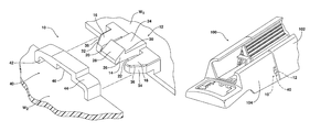
- FIG. 1 is an exploded perspective view illustrating the attachment device including an attachment head on a first workpiece and a receiver on a second workpiece.
- FIG. 2 is a detailed perspective view illustrating the attachment head fully seated and connected to the receiver.
- FIGS. 3 a -3 c are detailed cross-sectional views illustrating the process of connecting the attachment head to the receiver.
- FIG. 4 is a transverse cross-sectional view through the connected attachment head and receiver as illustrated in FIG. 2 .
- FIG. 5 is a perspective view illustrating the seat rail cover including the attachment device illustrated in FIGS. 1-4 .
- FIG. 1 illustrating the attachment device 10 for securing a first workpiece W 1 to a second workpiece W 2 .
- the attachment device 10 includes an attachment head 12 including a cantilever snap tab 14 , a first outboard locator tab 16 and a second outboard locator tab 18 .
- a first gap 20 is provided between the cantilever snap tab 14 and the first outboard locator tab 16 .
- a second gap 22 is provided between the cantilever snap tab 14 and the second outboard locator tab 18 .
- the cantilever snap tab 14 includes a resilient cantilever arm 24 , a locking lug 26 on a distal end of the cantilever arm and a first cam surface 28 on the locking lug. Further the locking lug 26 includes a locking shoulder 30 that is offset from the first and second outboard locator tabs 16 , 18 .
- first outboard locator tab 16 includes a first free end having a first guide surface 32 .
- second outboard locator tab 18 includes a second free end having a second guide surface 34 .
- first and second guide surfaces 32 , 34 converge toward the locking lug 26 .
- first outboard locator tab 16 and second outboard locator tab 18 both include beveled edges 36 .
- the attachment head 12 is connected to or carried on the first workpiece W 1 .
- the attachment device 10 also includes a receiver 40 .
- the receiver 40 includes an opening 42 for receiving and holding the cantilever snap tab 14 , the first outboard locator tab 16 and the second outboard locator tab 18 when the attachment head 12 is fully engaged and seated in the receiver 40 in order to complete the connection of the first and second workpieces W 1 , W 2 .
- the receiver 40 comprises a u-shaped band 44 .
- the u-shaped band 44 includes a channel 46 through which a locking lug 26 passes as the attachment head 12 is secured in the receiver 40 .
- the receiver 40 is connected to or carried on the second workpiece W 2 .
- FIG. 2 is a perspective view illustrating the attachment head 12 fully seated and locked in the receiver 40 so that the first and second workpieces W 1 , W 2 are tightly secured together.
- FIGS. 3 a -3 c illustrating the process of connecting the attachment head 12 with the receiver 40 .
- the first step involves generally aligning the attachment head 12 with the receiver 40 .
- the cantilever snap tab 14 , first outboard locator tab 16 and second outboard locator tab 18 of the attachment head 12 are then slowly inserted into the opening 42 formed by the band 44 .
- the narrow end of the first and second guide surfaces 32 , 34 engage the band 44 and function to help center the attachment head 12 in the receiver 40 and, more specifically, the cantilever snap tab 14 with the channel 46 in the band 44 .
- the cam surface 28 engages the band 44 and the resilient cantilever arm 24 pivots in the direction of action arrow B.
- the channel 46 in the band 44 provides the necessary clearance to allow the locking lug 26 to pass fully underneath the band 44 through the opening 42 .
- the cantilever snap tab 14 is offset from the locator tabs 16 , 18 so as to allow the necessary space S to depress the locking lug 26 and free the shoulder 30 from the band 44 .
- the outboard locator tabs 16 , 18 include the guide surfaces 32 , 34 that aid in centering and securing the attachment head 12 in the receiver 40 .
- the gaps 20 , 22 between the cantilever snap tab 14 and the locator tabs 16 , 18 ensure that the cantilever arm 24 has sufficient resilient movement to allow the connection of the attachment head 12 with the receiver 40 and the latching and unlatching of the locking shoulder 30 of the locking lug 26 with the band 44 .
- the outboard locator tabs 16 , 18 function to engage the sidewalls 48 of the band 44 thereby limiting or preventing any lateral side to side movement in the attachment device 10 see FIG. 4 .
- the engagement of the locking shoulder 30 with the band 44 and the abutting surfaces 50 of the two workpieces W 1 , W 2 restrict movement in the transverse direction (see FIG. 3 c ).
- the engagement between the relatively rigid locator tabs 16 , 18 and the band 44 adjacent the channel 46 on one side and the workpiece W 1 on the other restrict movement in the vertical direction (seen FIG. 3 c ). Consequently it should be appreciated that the attachment device 10 restricts all the degrees of freedom so as to provide a secure and flush connection between the workpieces W 1 , W 2 that prevents rocking and is virtually free of play in any direction.
- the seat rail cover 100 includes a first cover section 102 carrying an attachment head 12 as discussed above and illustrated in detail in FIG. 1 . Further, the seat rail cover 100 includes a second cover section 104 carrying a receiver 40 including an opening 42 as discussed above and illustrated in detail in FIG. 1 .
- the two cover sections 102 , 104 are connected together by the attachment device 10 . As described above and illustrated in detail in FIGS. 3 a -3 c , this is done by inserting the attachment head 12 on the first cover section 102 into the receiver 40 in the second cover section 104 until it is fully seated in a locked-in position.
Abstract
An attachment device is provided for securing a first workpiece to a second workpiece. The attachment device includes an attachment head and a receiver. The attachment head includes a cantilever snap tab, a first outboard locator tab and a second outboard locator tab. The receiver includes an opening for receiving and holding the cantilever snap tab, the first outboard locator tab and the second outboard locator tab.
Description
This document relates generally to attachment devices and, more particularly, to a new and improved attachment device incorporating a cantilever snap tab that is relatively inexpensive to produce, is easy to lock and unlock and that efficiently and effectively restricts different degrees of freedom to avoid movement between the work pieces that are connected together with the attachment device.
Attachment devices incorporating snap tabs are an efficient and effective way to secure two workpieces together. However, in the past, such devices have generally failed to provide the required restriction to all of the different degrees of freedom to eliminate play and undesired movement between the workpieces being connected together.
This document relates to a new and improved attachment device that addresses and solves this problem. The attachment device incorporates a cantilever snap tab. Advantageously, the attachment device can be packaged in a limited space, is relatively inexpensive to manufacture, very easy to lock and unlock and advantageously provides efficient and effective restriction of the different degrees of freedom to avoid movement between the workpieces being connected together and thereby provide a flush connection of high integrity between those workpieces.
In accordance with the purposes and benefits described herein, an attachment device is provided for securing a first workpiece to a second workpiece. That attachment device comprises an attachment head including a cantilever snap tab, a first outboard locator tab and a second outboard locator tab. In addition, the attachment device also comprises a receiver including an opening for receiving and holding the cantilever snap tab, the first outboard locator tab and the second outboard locator tab.
More specifically, the attachment head includes a first gap between the cantilever snap tab and the first outboard locator tab. Further, the attachment includes a second gap between the cantilever snap tab and the second outboard locator tab. Thus, the cantilever snap tab includes a cantilever arm between the outboard locator tabs. A locking lug is provided on a distal end of the cantilever arm. Further, a first cam surface is provided on the locking lug. The first outboard locator tab includes a first free end having a first guide service while the second outboard locator tab includes a second free end having a second guide surface. In one possible embodiment, the first and second guide surfaces converge toward the locking lug so as to provide a centering function when the attachment head is secured in the receiver. In one possible embodiment, the two outboard locator tabs both include beveled edges to aid in completing a smooth connection between the attachment head and the receiver. In one possible embodiment, the receiver includes a u-shaped band. The u-shaped band includes a channel through which the locking tab passes as the attachment head is secured to the receiver. The locking lug at the end of the locking tab includes a locking shoulder that is offset from the first outboard locator tab and the second locator tab. This shoulder engages the u-shaped band at the channel when the attachment head is seated and fully secured in the receiver.
In accordance with an additional aspect, a seat rail cover is provided. The seat rail cover comprises a first cover section carrying an attachment head including a cantilever snap tab, a first outboard locator tab and a second outboard locator tab. Further the seat rail cover includes a second cover section carrying a receiver including an opening for receiving and holding the cantilever snap tab, the first outboard locator tab and the second outboard locator tab.
In the following description, there are shown and described several preferred embodiments of the attachment device as well as of the seat rail cover. As it should be realized, the attachment device and seat rail cover are capable of other, different embodiments and their several details are capable of modification in various, obvious aspects all without departing from the attachment device and seat rail cover as set forth and described in the following claims. Accordingly, the drawings and descriptions should be regarded as illustrative in nature and not as restrictive.
The accompanying drawing figures incorporated herein and forming a part of the specification, illustrate several aspects of the attachment device and seat rail cover and together with the description serve to explain certain principles thereof. In the drawing figures:
Reference will now be made in detail to the present preferred embodiments of the attachment device and seat rail cover, examples of which are illustrated in the accompanying drawing figures.
Reference is now made to FIG. 1 illustrating the attachment device 10 for securing a first workpiece W1 to a second workpiece W2. As illustrated, the attachment device 10 includes an attachment head 12 including a cantilever snap tab 14, a first outboard locator tab 16 and a second outboard locator tab 18. A first gap 20 is provided between the cantilever snap tab 14 and the first outboard locator tab 16. A second gap 22 is provided between the cantilever snap tab 14 and the second outboard locator tab 18.
As further illustrated, the cantilever snap tab 14, includes a resilient cantilever arm 24, a locking lug 26 on a distal end of the cantilever arm and a first cam surface 28 on the locking lug. Further the locking lug 26 includes a locking shoulder 30 that is offset from the first and second outboard locator tabs 16, 18.
As further illustrated, the first outboard locator tab 16 includes a first free end having a first guide surface 32. Similarly, the second outboard locator tab 18 includes a second free end having a second guide surface 34. As should be appreciated, the first and second guide surfaces 32, 34 converge toward the locking lug 26. As further illustrated, the first outboard locator tab 16 and second outboard locator tab 18 both include beveled edges 36. As illustrated in FIG. 1 , the attachment head 12 is connected to or carried on the first workpiece W1.
As further illustrated in FIG. 1 , the attachment device 10 also includes a receiver 40. The receiver 40 includes an opening 42 for receiving and holding the cantilever snap tab 14, the first outboard locator tab 16 and the second outboard locator tab 18 when the attachment head 12 is fully engaged and seated in the receiver 40 in order to complete the connection of the first and second workpieces W1, W2. In the illustrated embodiment, the receiver 40 comprises a u-shaped band 44. As illustrated, the u-shaped band 44 includes a channel 46 through which a locking lug 26 passes as the attachment head 12 is secured in the receiver 40. As illustrated in FIG. 1 , the receiver 40 is connected to or carried on the second workpiece W2. FIG. 2 is a perspective view illustrating the attachment head 12 fully seated and locked in the receiver 40 so that the first and second workpieces W1, W2 are tightly secured together.
Reference is now made to FIGS. 3a-3c illustrating the process of connecting the attachment head 12 with the receiver 40. As illustrated in FIG. 3a , the first step involves generally aligning the attachment head 12 with the receiver 40. The cantilever snap tab 14, first outboard locator tab 16 and second outboard locator tab 18 of the attachment head 12 are then slowly inserted into the opening 42 formed by the band 44. Here it should be appreciated that the narrow end of the first and second guide surfaces 32, 34 engage the band 44 and function to help center the attachment head 12 in the receiver 40 and, more specifically, the cantilever snap tab 14 with the channel 46 in the band 44. As the attachment head 12 and receiver 40 are pushed together (note action arrow A in FIG. 3b ) the cam surface 28 engages the band 44 and the resilient cantilever arm 24 pivots in the direction of action arrow B. The channel 46 in the band 44 provides the necessary clearance to allow the locking lug 26 to pass fully underneath the band 44 through the opening 42.
As best illustrated in FIG. 3c , once the attachment head 12 is fully seated in the receiver 40, the locking shoulder 30 clears the band 44 and the resilient cantilever arm 24 returns under resilient memory (note action arrow C) to its home position so that the locking shoulder 30 of the locking lug 26 engages the band 44 thereby locking the attachment head 12 in the receiver 40.
If and when it is ever desired to disconnect the first and second workpieces W1, W2, one presses downwardly on the lug 26 (note action arrow D in FIG. 3c ) so as to release the locking shoulder 30 from the band 44 and the attachment head 12 is then pulled back through the opening 42 until it is free from the receiver 40. Here it should be appreciated that the cantilever snap tab 14 is offset from the locator tabs 16, 18 so as to allow the necessary space S to depress the locking lug 26 and free the shoulder 30 from the band 44.
As noted above, the outboard locator tabs 16, 18 include the guide surfaces 32, 34 that aid in centering and securing the attachment head 12 in the receiver 40. The gaps 20, 22 between the cantilever snap tab 14 and the locator tabs 16, 18 ensure that the cantilever arm 24 has sufficient resilient movement to allow the connection of the attachment head 12 with the receiver 40 and the latching and unlatching of the locking shoulder 30 of the locking lug 26 with the band 44. In addition, the outboard locator tabs 16, 18 function to engage the sidewalls 48 of the band 44 thereby limiting or preventing any lateral side to side movement in the attachment device 10 see FIG. 4 . Of course, the engagement of the locking shoulder 30 with the band 44 and the abutting surfaces 50 of the two workpieces W1, W2 restrict movement in the transverse direction (see FIG. 3c ). Further, the engagement between the relatively rigid locator tabs 16, 18 and the band 44 adjacent the channel 46 on one side and the workpiece W1 on the other restrict movement in the vertical direction (seen FIG. 3c ). Consequently it should be appreciated that the attachment device 10 restricts all the degrees of freedom so as to provide a secure and flush connection between the workpieces W1, W2 that prevents rocking and is virtually free of play in any direction.
Reference is now made to FIG. 5 illustrating one possible application for the attachment device 10 in the form of a seat rail cover 100. As illustrated, the seat rail cover 100 includes a first cover section 102 carrying an attachment head 12 as discussed above and illustrated in detail in FIG. 1 . Further, the seat rail cover 100 includes a second cover section 104 carrying a receiver 40 including an opening 42 as discussed above and illustrated in detail in FIG. 1 . The two cover sections 102, 104 are connected together by the attachment device 10. As described above and illustrated in detail in FIGS. 3a-3c , this is done by inserting the attachment head 12 on the first cover section 102 into the receiver 40 in the second cover section 104 until it is fully seated in a locked-in position.
The foregoing has been presented for purposes of illustration and description. It is not intended to be exhaustive or to limit the embodiments to the precise form disclosed. Obvious modifications and variations are possible in light of the above teachings. All such modifications and variations are within the scope of the appended claims when interpreted in accordance with the breadth to which they are fairly, legally and equitably entitled.
Claims (6)
1. A combination of an attachment device, a first workpiece, and a second workpiece, the attachment device comprising:
an attachment head carried on said first workpiece, said attachment head including a cantilever snap tab, a first outboard locator tab and a second outboard locator tab, wherein each of the first and second outboard locator tabs having an uppermost planar surface, wherein said cantilever snap tab includes a cantilever arm having a top planar surface, a locking lug on a distal end of said cantilever arm and a first cam surface on said locking lug, and wherein an entirety of the top planar surface of the cantilever arm is positioned in a different horizontal plane above the uppermost planar surface of each of the first and second outboard locator tabs;
a receiver carried on said second workpiece, said receiver including a substantially u-shaped band defining an opening for receiving and holding said cantilever snap tab, said first outboard locator tab and said second outboard locator tab, wherein said substantially u-shaped band includes a channel; and
a first gap between said cantilever snap tab and said first outboard locator tab and a second gap between said cantilever snap tab and said second outboard locator tab; and wherein said locking lug passes through said channel as said attachment head is secured to said receiver;
wherein said first outboard locator tab includes a first free end having a first guide surface and said second outboard locator tab includes a second free end having a second guide surface, and wherein said first guide surface and said second guide surface converge toward said locking lug.
2. The combination of claim 1 , wherein said locking lug includes a locking shoulder offset from said first outboard locator tab and said second outboard locator tab.
3. The combination of claim 2 , wherein said first outboard locator tab and said second outboard locator tab both include beveled edges.
4. A seat rail cover, comprising:
a first cover section carrying an attachment head including a cantilever snap tab, a first outboard locator tab and a second outboard locator tab, wherein each of the first and second outboard locator tabs having an uppermost planar surface, wherein said cantilever snap tab includes a cantilever arm having a top planar surface, a locking lug on a distal end of said cantilever arm and a first cam surface on said locking lug, and wherein an entirety of the top planar surface of the cantilever arm is positioned in a different horizontal plane above the uppermost planar surface of each of the first and second outboard locator tabs;
a second cover section carrying a receiver including a substantially u-shaped band defining an opening for receiving and holding said cantilever snap tab, said first outboard locator tab and said second outboard locator tab, said substantially u-shaped band includes a channel; and
a first gap between said cantilever snap tab and said first outboard locator tab and a second gap between said cantilever snap tab and said second outboard locator tab and wherein said locking lug passes through said channel as said attachment head is secured to said receiver;
wherein said first outboard locator tab includes a first free end having a first guide surface and said second outboard locator tab includes a second free end having a second guide surface, and wherein said first guide surface and said second guide surface converge toward said locking lug.
5. The seat rail cover of claim 4 , wherein said locking lug includes a locking shoulder offset from said first outboard locator tab and said second outboard locator tab.
6. The seat rail cover of claim 5 , wherein said first outboard locator tab and said second outboard locator tab both include beveled edges.
Priority Applications (4)
| Application Number | Priority Date | Filing Date | Title |
|---|---|---|---|
| US14/624,661 US9676297B2 (en) | 2015-02-18 | 2015-02-18 | Cantilever snap tab attachment device |
| RU2016104529A RU2695835C2 (en) | 2015-02-18 | 2016-02-11 | Fastener for securing first part to second part and seat guide cover |
| MX2016002068A MX370473B (en) | 2015-02-18 | 2016-02-16 | Cantilever snap tab attachment device. |
| CN201620125599.6U CN205478776U (en) | 2015-02-18 | 2016-02-17 | A attach equipment of connecing and seat track lid for inciting somebody to action first work piece fastens second work piece |
Applications Claiming Priority (1)
| Application Number | Priority Date | Filing Date | Title |
|---|---|---|---|
| US14/624,661 US9676297B2 (en) | 2015-02-18 | 2015-02-18 | Cantilever snap tab attachment device |
Publications (2)
| Publication Number | Publication Date |
|---|---|
| US20160236592A1 US20160236592A1 (en) | 2016-08-18 |
| US9676297B2 true US9676297B2 (en) | 2017-06-13 |
Family
ID=56621926
Family Applications (1)
| Application Number | Title | Priority Date | Filing Date |
|---|---|---|---|
| US14/624,661 Active US9676297B2 (en) | 2015-02-18 | 2015-02-18 | Cantilever snap tab attachment device |
Country Status (4)
| Country | Link |
|---|---|
| US (1) | US9676297B2 (en) |
| CN (1) | CN205478776U (en) |
| MX (1) | MX370473B (en) |
| RU (1) | RU2695835C2 (en) |
Cited By (8)
| Publication number | Priority date | Publication date | Assignee | Title |
|---|---|---|---|---|
| US20170335870A1 (en) * | 2016-05-20 | 2017-11-23 | Yazaki North America, Inc. | Tuneless cantilever system |
| US10123590B2 (en) * | 2013-07-10 | 2018-11-13 | Illinois Tool Works Inc. | System and assembly for securing a buckle housing to a component |
| US10711813B2 (en) | 2017-12-12 | 2020-07-14 | Ford Global Technologies, Llc | Attachment device providing double engagement for high retention |
| US10784743B2 (en) | 2018-08-14 | 2020-09-22 | Robert Bosch Gmbh | Housing including snap-fit connection between housing components |
| US20200370577A1 (en) * | 2019-05-22 | 2020-11-26 | Denso Thermal Systems S.P.A. | Connection device for interconnecting two components made of plastics material |
| US20220082118A1 (en) * | 2019-04-08 | 2022-03-17 | Hewlett-Packard Development Company, L.P. | Devices for retaining articles |
| US11451036B2 (en) * | 2018-05-25 | 2022-09-20 | Autonetworks Technologies, Ltd. | Fixing structure of wiring member |
| US11460214B2 (en) * | 2018-09-28 | 2022-10-04 | Toyoda Gosei Co., Ltd. | Duct device |
Families Citing this family (20)
| Publication number | Priority date | Publication date | Assignee | Title |
|---|---|---|---|---|
| US9474338B2 (en) * | 2013-10-11 | 2016-10-25 | Aplix | Fastener |
| US10188179B2 (en) * | 2013-10-11 | 2019-01-29 | Aplix | Fastener |
| US9676297B2 (en) * | 2015-02-18 | 2017-06-13 | Ford Global Technologies, Llc | Cantilever snap tab attachment device |
| US9949537B2 (en) * | 2015-03-06 | 2018-04-24 | Apple Inc. | Clasp mechanism for wrist-worn devices |
| US10328870B2 (en) * | 2016-07-25 | 2019-06-25 | Deere & Company | Work vehicle upholstery mounting system |
| CN107763037B (en) * | 2016-08-19 | 2021-03-16 | 福特环球技术公司 | Conical clamp |
| FR3057221B1 (en) * | 2016-10-11 | 2018-12-07 | Cera Tsc | COMPONENT OF SEAT OF MOTOR VEHICLE |
| DE202017100199U1 (en) * | 2017-01-16 | 2017-03-17 | Valeo Klimasysteme Gmbh | Heating, ventilation and / or air conditioning device for a motor vehicle |
| CN107380314A (en) * | 2017-07-27 | 2017-11-24 | 新乡市汉邦电动车配件有限公司 | A kind of hood structure on three-wheel electric motorcycle |
| US10688887B2 (en) * | 2017-08-30 | 2020-06-23 | Toyota Boshoku Kabushiki Kaisha | Sliding device |
| CN108506667A (en) * | 2018-04-07 | 2018-09-07 | 佛山市亿永创网络科技有限公司 | A kind of house anti-theft monitoring device |
| CN109131678B (en) * | 2018-08-26 | 2021-05-18 | 深圳市领航致远科技有限公司 | Car shell of car and car of riding instead of walk |
| JP6975976B2 (en) * | 2018-09-27 | 2021-12-01 | ヒロホー株式会社 | Transport container |
| EP3884132A4 (en) * | 2018-11-20 | 2022-08-03 | Femas Metal Sanayi Ve Ticaret Anonim Sirketi | Hood hinge assembly |
| JP7010871B2 (en) * | 2019-03-22 | 2022-01-26 | ファナック株式会社 | Parts assembly structure and automatic assembly system with disengagement prevention function |
| US10857954B1 (en) * | 2019-07-29 | 2020-12-08 | Toyota Motor Engineering & Manufacturing North America, Inc. | Clip assemblies |
| JP7360620B2 (en) * | 2019-11-19 | 2023-10-13 | 株式会社リコー | Parts, cooling equipment and image forming equipment |
| CN111924270B (en) * | 2020-07-29 | 2022-05-20 | 上海美瑞实业有限公司 | Automatic interlocking structure, storage box and storage box assembly |
| KR102317642B1 (en) * | 2020-12-22 | 2021-10-26 | 삼원액트 주식회사 | Unit bracket, bracket |
| DE102021101024A1 (en) | 2021-01-19 | 2022-07-21 | Valeo Systèmes d'Éssuyage SAS | wiper motor |
Citations (26)
| Publication number | Priority date | Publication date | Assignee | Title |
|---|---|---|---|---|
| US3409858A (en) * | 1966-08-29 | 1968-11-05 | Molex Products Co | Electrical connector having resilient arcuately bendable locking means |
| US4212415A (en) * | 1978-01-09 | 1980-07-15 | Refreshment Machinery Incorporated | Housing and module therefor |
| US4541036A (en) * | 1984-07-06 | 1985-09-10 | General Motors Corporation | Latch for terminal block |
| US4825515A (en) * | 1988-02-25 | 1989-05-02 | Wolterstorff Jr Donald A | Safety buckle |
| USD345293S (en) * | 1992-05-11 | 1994-03-22 | Pelikan, Inc. | Lockable latch assembly for a video cassette case |
| US5529297A (en) | 1993-11-08 | 1996-06-25 | Btm Corporation | Clamp having internal snap-fit attachments |
| US5577779A (en) * | 1994-12-22 | 1996-11-26 | Yazaki Corporation | Snap fit lock with release feature |
| US5657893A (en) * | 1993-08-23 | 1997-08-19 | Plastech Industries Pty Limited | Security container with releasably locking receptacle and lid |
| US5699601A (en) * | 1995-08-30 | 1997-12-23 | Ford Motor Company | Snap tab fastener and disassembly tool therefor |
| US5706672A (en) * | 1995-04-20 | 1998-01-13 | Fujitsu General Limited | Air conditioner |
| US5800208A (en) * | 1995-08-01 | 1998-09-01 | Yazaki Corporation | Movable connector-mounting construction |
| US6421889B1 (en) * | 2001-05-31 | 2002-07-23 | Vinsonic Industrial Co., Ltd. | Buckle structure |
| US6478346B1 (en) * | 1998-07-14 | 2002-11-12 | Firma Andreas Stihl Ag & Co. | Snap closure |
| US6684466B2 (en) * | 2001-12-17 | 2004-02-03 | Ykk Corporation Of America | Three point release buckle assembly |
| DE10244328A1 (en) | 2002-09-23 | 2004-05-13 | Volkswagen Ag | Sliding table module for vehicle, fixed into position by snap fit connection operated by handles connected to lever |
| US6901632B2 (en) * | 2003-09-15 | 2005-06-07 | Deere & Company | Coupling assembly |
| US20100272507A1 (en) | 2009-04-24 | 2010-10-28 | Toyota Motor Engineering & Manufacturing North America, Inc. | Easy install guide slot with snap tab |
| US7909371B1 (en) * | 2007-06-07 | 2011-03-22 | Central Garden And Pet Company | Vivarium cover locking clip |
| US8042830B2 (en) | 2006-09-01 | 2011-10-25 | Takata-Petri Ag | Device for snap-fastening an airbag unit in a subassembly of a motor vehicle, especially in a steering wheel |
| DE102011120490A1 (en) | 2011-12-08 | 2013-06-13 | Gm Global Technology Operations, Llc | Arrangement for steering wheel of motor vehicle, has guide units formed of guide bushings and guide pins, where airbag-module is guided by guide units relative to steering wheel in axle direction of steering column receptacle of wheel |
| US20140159382A1 (en) | 2011-07-27 | 2014-06-12 | Husqvarna Consumer Outdoor Products, N.A., Inc. | Snap Feature Providing Component Attachment |
| US8943655B2 (en) * | 2009-11-30 | 2015-02-03 | Daiwa Kasei Industry Co., Ltd. | Clip |
| US8944044B2 (en) * | 2008-07-09 | 2015-02-03 | Electrolux Home Products Corporation N.V. | One-piece fastening element for a cooking hob and a cooking hob with one-piece fastening elements |
| US9190818B2 (en) * | 2013-10-11 | 2015-11-17 | Sumitomo Wiring Systems, Ltd. | Electrical connection box |
| US20150329082A1 (en) * | 2014-05-19 | 2015-11-19 | Nhk Spring Co., Ltd. | Vehicle resin part and vehicle resin part manufacturing method |
| US20160236592A1 (en) * | 2015-02-18 | 2016-08-18 | Ford Global Technologies, Llc | Cantilever snap tab attachment device |
Family Cites Families (1)
| Publication number | Priority date | Publication date | Assignee | Title |
|---|---|---|---|---|
| DE202010008626U1 (en) * | 2010-09-24 | 2011-12-28 | Brose Fahrzeugteile Gmbh & Co. Kommanditgesellschaft, Hallstadt | clip element |
-
2015
- 2015-02-18 US US14/624,661 patent/US9676297B2/en active Active
-
2016
- 2016-02-11 RU RU2016104529A patent/RU2695835C2/en not_active IP Right Cessation
- 2016-02-16 MX MX2016002068A patent/MX370473B/en active IP Right Grant
- 2016-02-17 CN CN201620125599.6U patent/CN205478776U/en active Active
Patent Citations (26)
| Publication number | Priority date | Publication date | Assignee | Title |
|---|---|---|---|---|
| US3409858A (en) * | 1966-08-29 | 1968-11-05 | Molex Products Co | Electrical connector having resilient arcuately bendable locking means |
| US4212415A (en) * | 1978-01-09 | 1980-07-15 | Refreshment Machinery Incorporated | Housing and module therefor |
| US4541036A (en) * | 1984-07-06 | 1985-09-10 | General Motors Corporation | Latch for terminal block |
| US4825515A (en) * | 1988-02-25 | 1989-05-02 | Wolterstorff Jr Donald A | Safety buckle |
| USD345293S (en) * | 1992-05-11 | 1994-03-22 | Pelikan, Inc. | Lockable latch assembly for a video cassette case |
| US5657893A (en) * | 1993-08-23 | 1997-08-19 | Plastech Industries Pty Limited | Security container with releasably locking receptacle and lid |
| US5529297A (en) | 1993-11-08 | 1996-06-25 | Btm Corporation | Clamp having internal snap-fit attachments |
| US5577779A (en) * | 1994-12-22 | 1996-11-26 | Yazaki Corporation | Snap fit lock with release feature |
| US5706672A (en) * | 1995-04-20 | 1998-01-13 | Fujitsu General Limited | Air conditioner |
| US5800208A (en) * | 1995-08-01 | 1998-09-01 | Yazaki Corporation | Movable connector-mounting construction |
| US5699601A (en) * | 1995-08-30 | 1997-12-23 | Ford Motor Company | Snap tab fastener and disassembly tool therefor |
| US6478346B1 (en) * | 1998-07-14 | 2002-11-12 | Firma Andreas Stihl Ag & Co. | Snap closure |
| US6421889B1 (en) * | 2001-05-31 | 2002-07-23 | Vinsonic Industrial Co., Ltd. | Buckle structure |
| US6684466B2 (en) * | 2001-12-17 | 2004-02-03 | Ykk Corporation Of America | Three point release buckle assembly |
| DE10244328A1 (en) | 2002-09-23 | 2004-05-13 | Volkswagen Ag | Sliding table module for vehicle, fixed into position by snap fit connection operated by handles connected to lever |
| US6901632B2 (en) * | 2003-09-15 | 2005-06-07 | Deere & Company | Coupling assembly |
| US8042830B2 (en) | 2006-09-01 | 2011-10-25 | Takata-Petri Ag | Device for snap-fastening an airbag unit in a subassembly of a motor vehicle, especially in a steering wheel |
| US7909371B1 (en) * | 2007-06-07 | 2011-03-22 | Central Garden And Pet Company | Vivarium cover locking clip |
| US8944044B2 (en) * | 2008-07-09 | 2015-02-03 | Electrolux Home Products Corporation N.V. | One-piece fastening element for a cooking hob and a cooking hob with one-piece fastening elements |
| US20100272507A1 (en) | 2009-04-24 | 2010-10-28 | Toyota Motor Engineering & Manufacturing North America, Inc. | Easy install guide slot with snap tab |
| US8943655B2 (en) * | 2009-11-30 | 2015-02-03 | Daiwa Kasei Industry Co., Ltd. | Clip |
| US20140159382A1 (en) | 2011-07-27 | 2014-06-12 | Husqvarna Consumer Outdoor Products, N.A., Inc. | Snap Feature Providing Component Attachment |
| DE102011120490A1 (en) | 2011-12-08 | 2013-06-13 | Gm Global Technology Operations, Llc | Arrangement for steering wheel of motor vehicle, has guide units formed of guide bushings and guide pins, where airbag-module is guided by guide units relative to steering wheel in axle direction of steering column receptacle of wheel |
| US9190818B2 (en) * | 2013-10-11 | 2015-11-17 | Sumitomo Wiring Systems, Ltd. | Electrical connection box |
| US20150329082A1 (en) * | 2014-05-19 | 2015-11-19 | Nhk Spring Co., Ltd. | Vehicle resin part and vehicle resin part manufacturing method |
| US20160236592A1 (en) * | 2015-02-18 | 2016-08-18 | Ford Global Technologies, Llc | Cantilever snap tab attachment device |
Non-Patent Citations (6)
| Title |
|---|
| English translation of DE102011120490. |
| English translation of DE10244328. |
| Snap Fit Calculator, www2.basf.us/businesses/pasticportal/pp-techRes-tools-snapfit-en.html, 1 page. |
| Snap Fit Calculator, www2.basf.us/businesses/pasticportal/pp—techRes—tools—snapfit—en.html, 1 page. |
| Snap Fit Design, www.gotstogo.com/misc/engineering-info/snap-design.htm, 5 pages. |
| Snap Fit Design, www.gotstogo.com/misc/engineering—info/snap—design.htm, 5 pages. |
Cited By (11)
| Publication number | Priority date | Publication date | Assignee | Title |
|---|---|---|---|---|
| US10123590B2 (en) * | 2013-07-10 | 2018-11-13 | Illinois Tool Works Inc. | System and assembly for securing a buckle housing to a component |
| US20170335870A1 (en) * | 2016-05-20 | 2017-11-23 | Yazaki North America, Inc. | Tuneless cantilever system |
| US10865819B2 (en) * | 2016-05-20 | 2020-12-15 | Yazaki North America, Inc. | Tuneless cantilever system |
| US10711813B2 (en) | 2017-12-12 | 2020-07-14 | Ford Global Technologies, Llc | Attachment device providing double engagement for high retention |
| US11451036B2 (en) * | 2018-05-25 | 2022-09-20 | Autonetworks Technologies, Ltd. | Fixing structure of wiring member |
| US10784743B2 (en) | 2018-08-14 | 2020-09-22 | Robert Bosch Gmbh | Housing including snap-fit connection between housing components |
| US11460214B2 (en) * | 2018-09-28 | 2022-10-04 | Toyoda Gosei Co., Ltd. | Duct device |
| US20220082118A1 (en) * | 2019-04-08 | 2022-03-17 | Hewlett-Packard Development Company, L.P. | Devices for retaining articles |
| US11815125B2 (en) * | 2019-04-08 | 2023-11-14 | Hewlett-Packard Development Company, L.P. | Devices for retaining articles |
| US20200370577A1 (en) * | 2019-05-22 | 2020-11-26 | Denso Thermal Systems S.P.A. | Connection device for interconnecting two components made of plastics material |
| US11746809B2 (en) * | 2019-05-22 | 2023-09-05 | Denso Thermal Systems S.P.A. | Connection device for interconnecting two components made of plastics material |
Also Published As
| Publication number | Publication date |
|---|---|
| RU2695835C2 (en) | 2019-07-29 |
| MX370473B (en) | 2019-12-13 |
| CN205478776U (en) | 2016-08-17 |
| RU2016104529A3 (en) | 2019-05-31 |
| RU2016104529A (en) | 2017-08-16 |
| MX2016002068A (en) | 2016-08-17 |
| US20160236592A1 (en) | 2016-08-18 |
Similar Documents
| Publication | Publication Date | Title |
|---|---|---|
| US9676297B2 (en) | Cantilever snap tab attachment device | |
| US9425534B2 (en) | Lever-type electrical connector with connector positioning assurance member | |
| US10634281B2 (en) | Cast-in-place anchor assembly | |
| RU2453738C2 (en) | Attachment device and tool for locking said device | |
| US20110108697A1 (en) | Seat track apparatus | |
| TWI548155B (en) | Connector | |
| US9240817B2 (en) | Wall fastener for wireless transmission module | |
| US10087660B2 (en) | Door locking device and method for preventing door from opening during side collision | |
| KR20150041064A (en) | Panel-fixed connector device | |
| JP2016126841A (en) | Lever type connector | |
| KR20180095831A (en) | Vehicle door handle device | |
| US20160309854A1 (en) | Buckle Connector | |
| CN109116478B (en) | Pluggable transceiver module | |
| US10415734B2 (en) | Pipe coupling | |
| US20190178270A1 (en) | Attachment device providing double engagement for high retention | |
| KR101887834B1 (en) | Electrical connector | |
| JP2016072170A (en) | Connector holder | |
| US10040374B2 (en) | Seat slide device | |
| JP6702965B2 (en) | Connector assembly having connector position assurance member | |
| US7278869B1 (en) | Confined envelope connector system | |
| CN104695767B (en) | Key for vehicle device | |
| JP2019068722A (en) | Cover unit | |
| US8602808B2 (en) | Holder for two plugs | |
| KR101398652B1 (en) | Combined lintel assembly for construction work | |
| US20090089987A1 (en) | Device for fastening an accessory to a support part |
Legal Events
| Date | Code | Title | Description |
|---|---|---|---|
| AS | Assignment |
Owner name: FORD GLOBAL TECHNOLOGIES, LLC, MICHIGAN Free format text: ASSIGNMENT OF ASSIGNORS INTEREST;ASSIGNORS:PENICHE, ENRIQUE GRANELL;ORTIZ HERNANDEZ, EDGARDO FABRICIO;REEL/FRAME:034977/0581 Effective date: 20150213 |
|
| STCF | Information on status: patent grant |
Free format text: PATENTED CASE |
|
| MAFP | Maintenance fee payment |
Free format text: PAYMENT OF MAINTENANCE FEE, 4TH YEAR, LARGE ENTITY (ORIGINAL EVENT CODE: M1551); ENTITY STATUS OF PATENT OWNER: LARGE ENTITY Year of fee payment: 4 |