US9686668B2 - Method and apparatus for intra-network roaming for IP telephony network - Google Patents
Method and apparatus for intra-network roaming for IP telephony network Download PDFInfo
- Publication number
- US9686668B2 US9686668B2 US14/333,490 US201414333490A US9686668B2 US 9686668 B2 US9686668 B2 US 9686668B2 US 201414333490 A US201414333490 A US 201414333490A US 9686668 B2 US9686668 B2 US 9686668B2
- Authority
- US
- United States
- Prior art keywords
- internet
- telephony
- telephony device
- customer
- network
- Prior art date
- Legal status (The legal status is an assumption and is not a legal conclusion. Google has not performed a legal analysis and makes no representation as to the accuracy of the status listed.)
- Active
Links
Images


Classifications
-
- H—ELECTRICITY
- H04—ELECTRIC COMMUNICATION TECHNIQUE
- H04W—WIRELESS COMMUNICATION NETWORKS
- H04W8/00—Network data management
- H04W8/02—Processing of mobility data, e.g. registration information at HLR [Home Location Register] or VLR [Visitor Location Register]; Transfer of mobility data, e.g. between HLR, VLR or external networks
-
- H—ELECTRICITY
- H04—ELECTRIC COMMUNICATION TECHNIQUE
- H04L—TRANSMISSION OF DIGITAL INFORMATION, e.g. TELEGRAPHIC COMMUNICATION
- H04L65/00—Network arrangements, protocols or services for supporting real-time applications in data packet communication
- H04L65/1066—Session management
- H04L65/1073—Registration or de-registration
-
- H—ELECTRICITY
- H04—ELECTRIC COMMUNICATION TECHNIQUE
- H04L—TRANSMISSION OF DIGITAL INFORMATION, e.g. TELEGRAPHIC COMMUNICATION
- H04L65/00—Network arrangements, protocols or services for supporting real-time applications in data packet communication
- H04L65/1066—Session management
- H04L65/1096—Supplementary features, e.g. call forwarding or call holding
-
- H—ELECTRICITY
- H04—ELECTRIC COMMUNICATION TECHNIQUE
- H04W—WIRELESS COMMUNICATION NETWORKS
- H04W60/00—Affiliation to network, e.g. registration; Terminating affiliation with the network, e.g. de-registration
- H04W60/04—Affiliation to network, e.g. registration; Terminating affiliation with the network, e.g. de-registration using triggered events
-
- H—ELECTRICITY
- H04—ELECTRIC COMMUNICATION TECHNIQUE
- H04M—TELEPHONIC COMMUNICATION
- H04M7/00—Arrangements for interconnection between switching centres
- H04M7/006—Networks other than PSTN/ISDN providing telephone service, e.g. Voice over Internet Protocol (VoIP), including next generation networks with a packet-switched transport layer
-
- H—ELECTRICITY
- H04—ELECTRIC COMMUNICATION TECHNIQUE
- H04W—WIRELESS COMMUNICATION NETWORKS
- H04W8/00—Network data management
- H04W8/02—Processing of mobility data, e.g. registration information at HLR [Home Location Register] or VLR [Visitor Location Register]; Transfer of mobility data, e.g. between HLR, VLR or external networks
- H04W8/08—Mobility data transfer
- H04W8/12—Mobility data transfer between location registers or mobility servers
Definitions
- the technology relates to telecommunications, and in particular to Internet Protocol (IP) telephone systems that are accessible to mobile telephony devices.
- IP Internet Protocol
- IP Internet Protocol
- IP Internet Protocol
- the types of communications may be, for example, telephone calls, video calls, text and video messages, and other forms of telephony and data communications.
- the users of the Internet Protocol (IP) telephony system typically gain access to the Internet using an Internet service provider so that they can communicate via the IP telephony system.
- Some users or customers of the IP telephony system may engage in communications using telephony devices that are connected by physical lines such as cables or wires to an access point such as an internet port.
- Such wired telephony devices may, thanks to the services of the IP telephony system, be moved from one physical location to another physical location, but at each such physical location are physically connected in a wired manner to the respective access point.
- Other users or customers of the IP telephony system may possess mobile or wireless telephony devices, such as a wireless terminal, user equipment (UE), mobile phone, smart phone, or laptop, tablet, or other device with mobile termination.
- a mobile telephony device When such a mobile telephony device is within coverage of an appropriate wireless network (e.g., WiFi or WiMax network) that has connection to the a data network such as the Internet, the communications involving the mobile telephony device may be handled by the IP telephony system in conjunction with the wireless network.
- the communications may occur wirelessly between the mobile telephony device and a wireless access point of the wireless network, with the wireless access point in turn being connected to an Internet portal. Access in this manner to the Internet portal enables the mobile telephony device to capitalize upon the service of the IP telephony system in economically routing the communications through the Internet, rather than over existing non-Internet service carriers.
- the mobile telephony device may instead be served by other carriers and/or services using one or more mobile radio access networks.
- Such mobile radio access networks typically comprise plural base stations which have both radio frequency transmitting and receiving capabilities to serve macro cells.
- a macro cell is essentially defined by the extent of the transmitting and receiving capabilities of the base station.
- the mobile telephony devices located within the cell may communicate with the radio access network through the base station (unless the customer also happens to be within range of another wireless network, such as a WiFi or WiMax wireless network or the like, and exercises the option to use the other wireless network instead of the radio access network).
- a “macro” base station may be called a “radio base station”, “base station”, NodeB, eNodeB, or the like.
- Radio access networks allow a mobile telephony device to roam from cell to cell, either within the same radio access network and radio access technology, or even to roam between cells of differing radio access network and/or radio access technologies.
- Such roaming between macro cells and technologies of radio access networks typically involves an operation or procedure known as “location update”, or some similar operation.
- a switch or other element in a Chinese mobile network detects activation of the mobile telephony device.
- the Chinese mobile network sends a location update type message to a home location register (HLR) of the American home carrier.
- HLR home location register
- the location update message informs the American home carrier that the mobile telephony device is now within service of the Chinese mobile network, so that the American home carrier should transfer all incoming calls directed to the mobile telephony device to the Chinese mobile network.
- any such new call is initially directed to the American home carrier.
- the American home carrier Upon receipt of the new incoming call to the mobile telephony device the American home carrier checks its home location register and thus determines that the mobile telephony device is now serviced by the Chinese mobile network. Accordingly, the American home carrier sends a message to the Chinese mobile network, asking for a registration number (a temporary telephone number assigned by the Chinese mobile network to the mobile telephony device) recognizable by the Chinese mobile network for the mobile telephony device now serviced in China.
- a registration number a temporary telephone number assigned by the Chinese mobile network to the mobile telephony device
- the American carrier Upon receiving from the Chinese mobile network the Chinese-provided registration number for the mobile telephony device, the American carrier transfers the incoming call using the Chinese-provided registration number to the Chinese mobile network. In this manner the Chinese mobile network recognizes the transferred incoming call to the mobile telephony device, and can route the transferred incoming call through the Chinese mobile network to the mobile telephony device.
- the location update procedure described above applies to roaming mobile telephony devices that are served by non-IP telephony systems.
- Both IP telephony systems and non-IP telephony systems both provide an additional service known as call forwarding.
- call forwarding service In a call forwarding service, incoming calls to a customer's nominal directory number are instead routed to an alternate number specified by the customer. Such alternate number may be stored in a home location register or the like maintained by the home carrier network.
- the call forwarding service may be available both to wired and wirelessly connected telephony devices. Examples of how call forwarding services may be beneficially used by mobile/wireless telephony devices are described in one or more of the following United States patent applications, all of which are incorporated herein by reference: U.S. Pat. No.
- the customer or subscriber may input a string of numbers, e.g., a code such as “#21*xxx* (wherein “xxx” is the call forwarding number to be used upon implementation of the call forwarding operation).
- code a code results in a signal being transmitted to the home carrier that informs the home carrier to start forwarding calls to the number specified in the string (or a number pre-stored with the home carrier) instead of the nominal directory number associated with the wireless telephony device.
- the forwarding number may be a number associated with an IP telephony system, e.g., a server of an IP telephony system. Thereafter, the IP-telephony system may terminate the call over the IP telephony system network to the subscriber when the subscriber is in range of an appropriate internet-connected wireless network, such as Wi-Fi.
- the call forwarding service is thus implemented at the time of conscious, deliberate activation of the customer/subscriber, and remains in effect until the call forwarding service is removed by a similar conscious, deliberate act of the customer/subscriber. In essence, the call forwarding number remains permanently applied until specifically replaced by the customer/subscriber.
- prior art call forwarding services do not effectively cater to the roaming of mobile telephony devices.
- the technology disclosed herein concerns a method of operating an internet-based telephony system.
- the method comprises (1) determining that a telephony device associated with a customer of the internet-based telephony system has access to service of the internet-based telephony system.
- the method further comprises (2) sending a first location update signal to a public land mobile network associated with the customer.
- the first location update signal includes an identification of the internet-based telephony system as a network visited by the telephony device associated with the customer.
- the method further comprises thereafter (3) receiving an indication that the public land mobile network associated with the customer no longer considers the internet-based telephony system as being the network visited by the telephony device associated with the customer.
- the method further comprises (4) determining the telephony device associated with the customer and the internet-based telephony system are in data communication, and (5) sending a second location update signal to the public land mobile network associated with the customer to register again the internet-based telephony system as the network visited by the telephony device associated with the customer.
- the indication that the public land mobile network associated with the customer no longer considers the internet-based telephony system as being the network visited by the telephony device associated with the customer comprises a map-cancel-location-request signal.
- the method further comprises sending a network contention resolution signal to the telephony device.
- the network contention resolution signal is configured to either disable macro communication capability of the telephony device or provide a notification to the telephony device.
- the method further comprises determining that the telephony device is not participating in a service provided through a macro radio network, and sending a signal to disable macro communication capability of the telephony device so that the IP telephony system remains as the network visited by the telephony device associated with the customer.
- the act of determining that the telephony device is not participating in the service provided through the macro radio network comprises receiving an indication from the telephony device that the telephony device is not participating in the service provided through the macro radio network.
- the method further comprises sending a signal to disable macro communication capability of the telephony device so that the IP telephony system remains as the network visited by the telephony device associated with the customer; and then determining that the telephony device associated with the customer and the internet-based telephony system are no longer in data communication.
- the act of determining that the telephony device associated with the customer and the internet-based telephony system are in data communication comprises determining that a still-alive indication associated with the telephony device exists in a status database.
- the method further comprises the internet-based telephony system sending a prompt message to the telephony device and, upon receipt of a response to the prompt message, setting the data connection still-alive indication in the status database.
- act (4), and act (5) comprise a set of acts that may be repeated for plural iterations, and after act (5) has been performed a maximum number of times the act (4) and the act (5) are not performed for a next iteration.
- the method further comprises, after the internet-based telephony system receives a further indication that the public land mobile network associated with the customer no longer considers the internet-based telephony system as being the network visited by the telephony device associated with the customer, imposing a time delay before again performing act (4) and act (5).
- the further indication comprises plural further indications received either within a predetermined time period of one another or within a predetermined time period of location update signals previously sent by the Internet Protocol telephony system.
- the technology disclosed herein concerns an internet-based telephony system comprising a processor.
- the processor is configured to (1) determine that a telephony device associated with a customer of the internet-based telephony system has access to service of the internet-based telephony system.
- the processor is further configured to (2) send a first location update signal to a public land mobile network associated with the customer, the first location update signal including an identification of the internet-based telephony system as a network visited by the telephony device associated with the customer.
- the processor is further configured to (3) receive an indication that the public land mobile network associated with the customer no longer considers the internet-based telephony system as being the network visited by the telephony device associated with the customer.
- the processor is further configured to (4) determine that the telephony device associated with the customer and the internet-based telephony system are in data communication; and (5) send a second location update signal to the public land mobile network associated with the customer to register again the internet-based telephony system as the network visited by the telephony device associated with the customer.
- the indication that the public land mobile network associated with the customer no longer considers the internet-based telephony system as being the network visited by the telephony device associated with the customer comprises a map-cancel-location-request signal.
- the processor is configured to send a network contention resolution signal to the telephony device, the network contention resolution signal being configured to either: disable macro communication capability of the telephony device; or provide a notification to the telephony device.
- the processor is further configured to determine that the telephony device is not participating in a service provided through a macro radio network; and send a signal to the telephony device to disable macro communication capability of the telephony device.
- the processor is configured to determine that the telephony device is not participating in the service provided through the macro radio network by receiving an indication from the telephony device that the telephony device is not participating in the service provided through the macro radio network.
- the processor is configured to send a signal to disable macro communication capability of the telephony device so that the IP telephony system remains as the network visited by the telephony device associated with the customer; and then determine that the telephony device associated with the customer and the internet-based telephony system are no longer in data communication.
- the processor is configured to determine whether the telephony device associated with the customer and the internet-based telephony system are in data communication by making a determination that a still-alive indication associated with the telephony device still exists in a status database.
- the processor is configured to send a prompt message to the telephony device and, upon receipt of a response to the prompt message, to set the data connection still-alive indication in the status database.
- act (3), act (4), and act (5) comprise a set of acts that may be repeated for plural iterations
- the processor is configured so that after act (5) has been performed a maximum number of times the act (4) and the act (5) are not performed for a next iteration.
- the processor is configured, after the internet-based telephony system receives a further indication that the public land mobile network associated with the customer no longer considers the internet-based telephony system as being the network visited by the telephony device associated with the customer, to impose a time delay before again performing act (4) and act (5).
- the further indication comprises plural further indications received either within a predetermined time period of one another or within a predetermined time period of location update signals previously sent by the Internet Protocol telephony system.
- the technology disclosed herein concerns a method of operating a telephony device.
- the method comprises at least temporarily disabling macro communication capability of the telephony device when the telephony device is in data communication with an IP telephony system; and re-enabling the macro communication capability of the telephony device when the telephony device looses data communication with the IP telephony system.
- the method may further comprise providing a notification to the user of the telephony device to give the user an option of at least temporarily disabling the macro communication capability of the telephony device when the telephony device is in data communication with the IP telephony system.
- the technology disclosed herein concerns a telephony device comprising a processor configured to at least temporarily disable macro communication capability of the telephony device when the telephony device is in data communication with an IP telephony system; and re-enable the macro communication capability of the telephony device when the telephony device looses data communication with the IP telephony system.
- FIG. 1A is a diagrammatic view of a communications network comprising an Internet-based telephony system which facilitates intra-system roaming, showing location/situation of a telephony device in a first roaming position.
- FIG. 1B is a diagrammatic view of the communications network of FIG. 1A , showing further aspects of the network and location/situation of a telephony device in an exemplary second roaming position.
- FIG. 1C is a diagrammatic view of the communications network of FIG. 1A , showing further aspects of the network and location/situation of a telephony device in an exemplary third roaming position.
- FIG. 1D is a diagrammatic view of the communications network of FIG. 1A , showing further aspects of the network and location/situation of a telephony device in an exemplary fourth roaming position.
- FIG. 1E is a diagrammatic view of the communications network of FIG. 1A , showing further aspects of the network and location/situation of a telephony device in an exemplary fifth roaming position.
- FIG. 2 is a flowchart showing exemplary procedures performed by an intra-system roaming processor according to an exemplary embodiment and mode.
- FIG. 3 is a flowchart showing exemplary basic acts or steps comprising an update signaling procedure according to an exemplary embodiment and mode.
- FIG. 4 is a flowchart showing exemplary basic acts or steps comprising an incoming communication handling procedure according to an exemplary embodiment and mode.
- FIG. 5 is a schematic view of an exemplary embodiment of an Internet-based telephony system which facilitates intra-system roaming.
- FIG. 6 is a diagrammatic view showing in more detail example acts and/or signals comprising or occurring in a context of a location registration operation performed in conjunction with intra-system roaming.
- FIG. 7 is a diagrammatic view showing exemplary acts and/or signals comprising or occurring in a context of a communication connection operation performed in conjunction with intra-system roaming.
- FIG. 8 is a diagrammatic view showing exemplary acts and/or signals comprising or occurring in a context of a short message service (SMS) communication connection operation performed in conjunction with intra-system roaming.
- SMS short message service
- FIG. 9A , FIG. 9B , and FIG. 9C are diagrammatic views showing exemplary scenarios of movements of telephony devices which may cause location update operations.
- FIG. 11 is a schematic view of an exemplary embodiment of an Internet-based telephony system which facilitates intra-system roaming and includes an HLR reclamation feature.
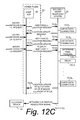
- FIG. 12 and FIG. 12A - FIG. 12D are diagrammatic views showing exemplary acts and/or signals comprising or occurring in a context of a scenario wherein a telephony device, still within coverage of an access point cell, hovers at or near a border between macro cells, according to various example implementations.
- FIG. 13 is a diagrammatic view showing exemplary implementations of a network contention resolution signal.
- FIG. 14 is a diagrammatic view illustrating an example embodiment and mode comprising confirming that a telephony device is not participating in a service provided through a macro network before sending a network contention resolution signal.
- FIG. 15A - FIG. 15C are flowcharts showing example routines performed by an internet protocol telephony service according to an example embodiment and mode.
- FIG. 16 is a schematic view of a wireless or mobile telephony device for which roaming is facilitated by an Internet-based telephony system which facilitates intra-system roaming.
- FIG. 17 is a flowchart showing exemplary basic acts or steps performed upon execution at a telephony device of a network access detection and registration routine according to an exemplary embodiment and mode.
- FIG. 18 is a schematic view shows an example of machine hardware comprising one or more processors for implementing aspects of an IP telephony system and a telephony device according to exemplary embodiments.
- block diagrams herein can represent conceptual views of illustrative circuitry or other functional units embodying the principles of the technology.
- any flow charts, state transition diagrams, pseudocode, and the like represent various processes which may be substantially represented in computer readable medium and so executed by a computer or processor, whether or not such computer or processor is explicitly shown.
- telephony communications is intended to encompass any type of communication that could pass back and forth between users of an IP telephony system. This includes audio and video telephone, text messages such as short message service (SMS) communications, video messages and any other form of telephony or data communication.
- SMS short message service
- IP telephony device This term is used to refer to any type of device which is capable of interacting with an IP telephony system to complete an audio or video telephone call or to send and receive text messages, and other forms of communications.
- An IP telephony device could be an IP telephone, a computer running IP telephony software, a telephone adapter which is itself connected to a normal analog telephone, or some other type of device capable of communicating via data packets.
- An IP telephony device could also be a cellular telephone or a portable computing device that runs a software application that enables the device to act as an IP telephone. Thus, a single device might be capable of operating as both a cellular telephone and an IP telephone.
- a mobile telephony device is intended to encompass multiple different types of devices.
- a mobile telephony device could be a cellular telephone.
- a mobile telephony device may be a mobile computing device that includes both cellular telephone capabilities and a wireless data transceiver that can establish a wireless data connection to a data network.
- Such a mobile computing device could run appropriate application software to conduct VoIP telephone calls via a wireless data connection.
- a mobile computing device such as an Apple iPhoneTM, a RIM Blackberry or a comparable device running Google's Android operating system could be a mobile telephony device.
- a mobile telephony device may be a device that is not traditionally used as a telephony device, but which includes a wireless data transceiver that can establish a wireless data connection to a data network. Examples of such devices include the Apple iPod TouchTM and the iPadTM. Such a device may act as a mobile telephony device once it is configured with appropriate application software.
- FIG. 1A shows a telephony system 20 , in context of an exemplary generic communications system 22 .
- the telephony system 20 may be an Internet (IP) telephony system
- IP Internet
- the telephony system 20 is shown as connected to a data communications network such as Internet 24 .
- a telephony device 30 which for sake of illustration happens to be a mobile or wireless telephony device such as a user equipment unit, smart phone, or laptop with mobile termination, for example, is associated with a customer of the telephony system 20 .
- the customer is not only a customer of telephony system 20 , but is also served by the customer's home public land mobile network (PLMN) 32 .
- the customer's home public land mobile network 32 is shown in FIG. 1A as comprising a PLMN gateway or switching center (GMSC) 34 , as well as a PLMN home location register (HLR) 36 .
- GMSC PLMN gateway or switching center
- HLR PLMN home location register
- Both home public land mobile network 32 and telephony system 20 are connected to the public switched telephone network (PSTN) 40 .
- the public switched telephone network (PSTN) 40 may comprise one or more radio access network(s) (RANs) 42 .
- the home public land mobile network 32 is connected to public switched telephone network (PSTN) 40 through the PLMN gateway 34 .
- Telephony system 20 is also connected to public switched telephone network (PSTN) 40 through its gateway(s), described hereinafter.
- FIG. 1A further shows telephony device 30 as being situated in a radio access network cell 44 which is served by base station 46 of a radio access network 42 .
- the base station 46 may be a base station controller (BSC), NodeB, eNodeB, or other type of base station.
- BSC base station controller
- NodeB NodeB
- eNodeB eNodeB
- the network cell 44 may be referred to as a macro cell and the base station 46 as a macro base station.
- macro base stations such as macro base station 46 communicate with wireless terminals using licensed frequencies.
- the former networks provide services such as call service and short message service (SMS), and typically include base stations which report to a radio network controller node and which may belong to a roaming area.
- the former networks additionally provide General Packet Radio Service (GPRS)/3G/LTE services and typically include base stations characterized as NodeB or eNodeB and for which routing areas are defined.
- GPRS General Packet Radio Service
- the base stations of both types of networks broadcast their roaming and routing area.
- FIG. 1A also shows telephony device 30 as being within a smaller cell 48 (e.g., a micro cell, home cell, pico cell, or femto cell) which is served by a wireless access point 50 of an internet-connected wireless access service.
- the access point 50 may provide Wi-Fi or WiMAX access to telephony device 30 .
- Wi-Fi is a technology that allows an electronic device to exchange data or connect to the Internet wirelessly using microwaves in the 2.4 GHz and 5 GHz bands, and thus includes any “wireless local area network (WLAN) products that are based on the Institute of Electrical and Electronics Engineers' (IEEE) 802.11 standards”.
- the smaller cell 48 may also be referred to as an access point cell.
- access points such as access point 50 communicate with wireless terminals using unlicensed frequencies.
- the telephony system 20 comprises intra-system roaming processor 60 .
- intra-system roaming processor 60 may comprise one or more processors, controllers, or servers, either co-located or distributed, that facilitate roaming of telephony device 30 within the territory in which the service of internet-based telephony system 20 is available, e.g., available through co-operation of wireless access points.
- An example of such an Internet-based telephony system 20 is a voice over IP (VoIP) telephony system.
- VoIP voice over IP
- the internet-based telephony system 20 may also be referred to as a “Communication over IP”, or “CoIP system”.
- the “intra-system” descriptor signifies that the roaming facilitated by processor 60 is roaming within the territory in which the service of internet-based telephony system 20 is available.
- the intra-system roaming processor 60 may also be referred to as “roaming within CoIP system processor” or, more simply, CoIP roaming processor that implements a “CoIP roaming” feature of the technology disclosed herein.
- FIG. 1B shows a situation in which telephony device 30 has roamed into access point cell 48 B of another access point 50 B.
- the cell 48 B may also be within the range of macro cell 44 , but is situated with respect to original access point cell 48 so that the telephony device 30 may engage in handoff or handover from access point cell 48 to access point cell 48 B without having to be served by base station 46 , e.g., the telephony device 30 may continually remain within coverage of the access points 50 and 50 B and thus stay within “coverage” of internet-based telephony system 20 .
- FIG. 1C shows a situation in which telephony device 30 has roamed away from access points such as 50 and 50 B (as indicated by roaming direction arrow 52 C) and therefore is no longer with in WiFi or WiMax coverage.
- the base station 46 C is configured to handle data connections, e.g., is a Node-B or eNodeB type base station which has a data connection such as GPRS/3G/LTE.
- the telephony device 30 is able to make a data connection through the licensed frequencies of the base station 46 C over the air interface, through appropriate core network nodes such as Serving GPRS Support Node (SGSN) 47 and GPRS Gateway Support Node (GGSN) 49 to internet 24 , and through internet 24 to telephony system 20 .
- SGSN Serving GPRS Support Node
- GGSN GPRS Gateway Support Node
- the telephony device 30 still has access through the data services of the macro cell to telephony system 20 , and thus remains “in coverage” in the situation of FIG. 1C .
- FIG. 1D shows by roaming direction arrow 52 D that telephony device 30 has roamed from the position of FIG. 1C to again be within coverage of another access point, i.e., access point 50 D.
- FIG. 1D shows telephony device 30 also remaining within coverage of telephony system 20 , and in particular again gaining WiFi type coverage.
- 1E is not a data-capable base station, e.g., does not have GPRS/3G/LTE capabilities, the telephony device 30 will be without data connection for a portion of the travel and during such data-less portion make a location update with respect to macro cell 44 E. Thus during the data-less portion of the travel depicted by arrow 52 E the telephony device 30 may not be within coverage of telephony system 20 . However, upon gaining access to access point cell 48 E the telephony device 30 may again be within coverage of telephony system 20 .
- FIG. 1A - FIG. 1E have illustrated telephony device 30 as being a wireless or mobile telephony device, it should be understood that the technology disclosed herein is not limited to wireless or mobile telephony devices. That is, telephony device connection to the internet-based telephony system 20 is not necessarily a wireless connection. For example, a user can use this roaming service of the presently disclosed technology by installing an application on a computer.
- the telephony device 30 is a wireless device and thus has mobility characteristics.
- wireless terminal may roam in and out of “coverage” of the internet-based telephony system 20 , or may roam between access points through which telephony device 30 is served by internet-based telephony system 20 and/or macro cells having data connection handling capability. Examples of such intra-system roaming have already been mentioned with respect to FIG. 1A , FIG. 1B , FIG. 1C , FIG. 1D , and FIG. 1E .
- FIG. 1A , FIG. 1B , FIG. 1C , FIG. 1D , and FIG. 1E Examples of such intra-system roaming have already been mentioned with respect to FIG. 1A , FIG. 1B , FIG. 1C , FIG. 1D , and FIG. 1E .
- FIG. 1A , FIG. 1B , FIG. 1C , FIG. 1D , and FIG. 1E Examples of such intra-system roaming have already been mentioned with respect to FIG. 1
- FIG. 1B shows a situation in which telephony device 30 has roamed between access points that are located so that their cells at least partially overlap and facilitate essentially continuous service of (e.g., access to) internet-based telephony system 20 during the roaming.
- FIG. 1C shows a situation in which roaming of telephony device 30 between access point 50 and 50 C is discontinuous in the sense of WiFi coverage, but nevertheless is still within coverage of telephony system 20 in view of the data connection handling capabilities of macro cell 46 C. The travel along arrow 52 E of FIG.
- 1E shows a discontinuous roaming with respect to internet-based telephony system 20 , in view of the fact that along at least a portion of travel path 52 E the telephony device 30 is not registered with internet-based telephony system 20 and may instead be served by a non-internet access provider, e.g., a radio access network of another carrier or network that does not have data connection handling capability.
- a non-internet access provider e.g., a radio access network of another carrier or network that does not have data connection handling capability.
- a new execution of update signaling procedure 62 need not occur.
- “access” to telephony system 20 means access to telephony system 20 after having previously been outside of telephony system 20 , and does not mean attachment to a different access point 50 .
- switching between different access points for data connection does not have any impact on the internet-based telephony system 20 , other than possibly to update the IP address of the telephony device 30 , e.g., in record 90 of location register database 74 , when the IP address is changed.
- the telephony device 30 may travel or roam in a manner such as that depicted by FIG. 1A - FIG. 1E .
- internet-based telephony system 20 receives notifications at different access times as telephony device 30 makes or receives access to service to the internet-based telephony system 20 .
- the telephony device 30 has been out of access of telephony system 20 (such as when coming within coverage of access point 50 E of FIG.
- the internet-based telephony system 20 after being out of coverage of telephony system 20 ) the internet-based telephony system 20 : (1) stores appropriate information regarding the telephony device 30 (e.g., customer number and IMSI); and (2) sends a location update signal (such as signal 6 - 5 of FIG. 6 ) to the public land mobile network 32 associated with the customer.
- the location update signal is configured by the telephony system to cause the home location network 32 to register the internet-based telephony system 20 as a network visited by the telephony device 30 associated with the customer.
- the location update signal may include the Global Title (GT) of internet-based telephony system 20 as an indication of current location of telephony device 30 .
- GT Global Title
- the internet-based telephony system 20 upon occurrence of an incoming communication directed a called number associated with a customer having an account with the internet-based telephony system which includes the telephony device 30 , the internet-based telephony system 20 : (3) provides the public land mobile network 32 associated with the customer with a roaming number that causes the public land mobile network associated with the customer to route the incoming communication to the internet-based telephony system 20 ; and (4) upon receiving the incoming communication at the roaming number from the public land mobile network 32 associated with the customer, routes the communication through the Internet 24 to an IP address for a device included in the customer account for the respective access time.
- intra-system roaming processor 60 is involved in at least two separate procedures or operations, both of which facilitate the intra-system or CoIP roaming.
- a first such procedure, location update signaling procedure 62 comprises generation of location update signaling, and particularly location update signaling which is configured to cause the home location network 32 for the customer to register the internet-based telephony system 20 as a network visited by a mobile telephony device 30 . Such generation occurs when telephony device 30 has access to service of the internet-based telephony system.
- FIG. 3 shows exemplary basic acts or steps which may comprise update signaling procedure 62 .
- such location update signaling generated by intra-system roaming processor 60 provides PLMN home location register (HLR) 36 with a Global Title (GT) address of telephony system 20 .
- HLR PLMN home location register
- GT Global Title
- FIG. 2 also shows a second procedure or operation, known as incoming communication handling procedure 64 .
- the incoming communication handling procedure 64 is performed by intra-system roaming processor 60 (as a result of previous implementation of the location update signaling) when the home public land mobile network 32 receives an incoming communication, e.g., an incoming call or SMS message for the telephony device 30 .
- FIG. 4 shows exemplary basic acts or steps which may comprise incoming communication handling procedure 64 .
- the intra-system roaming processor 60 executes the incoming communication handling procedure 64 to cause routing of the incoming communication through the Internet 24 to a device included in an account for the customer.
- a device included in an account for the customer may or may not be the telephony device 30 , depending on whether the customer has implemented any features such as call forwarding or ring list or the like.
- intra-system roaming processor 60 may detect communications with telephony device 30 through an access point 50 , and as a result may automatically execute update signaling procedure 62 upon such detection. In other situations the intra-system roaming processor 60 may detect data communications with telephony device 30 if telephony device 30 receives a broadcast from a data connection-capable (e.g., GPRS type) base station 46 , in the manner shown in FIG. 1C . For either situation—licensed frequency data connection through a macro cell as shown in FIG. 1C or unlicensed frequency data connection through a WiFi type access point 50 —intra-system roaming processor 60 is shown in FIG. 2 as also optionally performing access detection procedure 66 .
- a data connection-capable e.g., GPRS type
- update signaling procedure 62 may be performed as a result of execution by intra-system roaming processor 60 of coded instructions, stored on computer-readable non-transitory media, which comprise the respective procedures.
- the update signaling procedure 62 , incoming communication handling procedure 64 , and access detection procedure 66 may comprise a computer program product.
- FIG. 5 shows exemplary functionalities and/or units of internet-based telephony system 20 , as well as exemplary functionalities and/or units of intra-system roaming processor 60 according to a non-limiting, exemplary implementation embodiment.
- FIG. 5 shows internet-based telephony system 20 as comprising one or more IP telephony system gateway(s) 70 ; IP telephony system Internet ports 72 ; and an IP telephony system database, which includes IP telephony system location register database 74 .
- the internet-based telephony system 20 may be structured with different architectural units and functions in other implementations.
- the IP telephony system gateway(s) 70 is/are configured to send or receive various signals or messages. For example, the IP telephony system gateway(s) 70 send the location update signal to the home location network; receive a roaming number request signal; and receive an incoming communication routing signal from the home location network, as herein described.
- FIG. 5 further shows intra-system roaming processor 60 as comprising access monitor 76 ; connection unit 78 ; control unit 80 ; signal generator 82 ; signal handler 84 ; and location register manager or interface 86 .
- the access monitor 76 is configured to obtain certain information from the telephony device 30 when the telephony device has access to service to the internet-based telephony system 20 .
- Such information obtained upon access to service includes a customer identifier for the customer and the International mobile Subscriber Identity IMSI of the telephony device 30 .
- the customer identifier (CUST ID) may be a customer-selected user name or the like which is unique to the customer and agreed between the customer and telephony system 20 .
- the customer may also have a password.
- the customer identifier (CUST ID) and/or password are entered by the customer upon opening or activating an application of the telephony system 20 which is executed on the telephony device 30 , e.g., a CoIP application 88 (see FIG. 16 ).
- the IMSI is obtained from a mobile telephony device where it is stored in a Subscriber Identity Module (SIM) card, with each IMSI uniquely identifying the mobile telephony device, its home wireless network, and the home country of the home wireless network.
- SIM Subscriber Identity Module
- the signal generator 82 is adapted, when the telephony device 30 has access to service to the internet-based telephony system 20 , to configure a location update signal to cause the home location network 32 for the customer to register the internet-based telephony system 20 as a network visited by a telephony device associated with the customer.
- the signal handler 84 is configured, upon receipt of the roaming number request signal, to provide the home location network 32 with a roaming number.
- the roaming number is configured to cause the home location network 32 to route the incoming communication as an incoming communication routing signal to the internet-based telephony system 20 .
- the control unit 80 is configured to coordinate and sequence the actions of access monitor 76 ; connection unit 78 ; signal generator 82 ; signal handler 84 ; and location register manager or interface 86 .
- FIG. 5 also shows IP telephony system location register database 74 as comprising a record 90 for a particular customer of internet-based telephony system 20 .
- the record 90 is shown as comprising plural fields or information elements, including customer ID (CUST ID) field 92 ; roaming number field 94 ; customer IP address(es) field 96 (CUST IP ADDR(ES)); Mobile Subscriber Integrated Services Digital Network Number (MSISDN) field 97 ; International mobile Subscriber Identity (IMSI) field 98 ; and, Home Location Register (HLR) field 99 .
- customer ID customer ID
- MSISDN Mobile Subscriber Integrated Services Digital Network Number
- IMSI International mobile Subscriber Identity
- HLR Home Location Register
- the customer IP address which is stored in customer IP address(es) field 96 will be the IP address of the telephony device 30 .
- the customer may have one or more other IP addresses stored in IP address(es) field 96 , either in lieu of or in addition to the IP address of the telephony device 30 .
- the customer IP address(es) field 96 may include the IP address of one or more devices to which an incoming communication should be forwarded other than to telephony device 30 .
- customer IP address(es) field 96 may include IP address(es) of one or more devices in addition to or instead of the IP address of telephony device 30 .
- the telephony system 20 may receive notifications (e.g., push notifications) or responses to inquires from the telephony device 30 regarding any changed IP address of the telephony device 30 .
- a change of IP address may occur, for example, when the telephony device 30 changes networks.
- the IMSI is obtained from a mobile telephony device where it is stored in a Subscriber Identity Module (SIM) card.
- SIM Subscriber Identity Module
- MSISDN Mobile Subscriber Integrated Services Digital Network Number
- a SIM card has a unique IMSI that does not change, while the MSISDN can change in time, i.e. different MSISDNs can be associated with the SIM.
- FIG. 3 shows exemplary basic acts or steps which may comprise update signaling procedure 62 according to an exemplary embodiment and mode.
- update signaling procedure 62 is performed by intra-system roaming processor 60 when a telephony device associated with a customer of the telephony system 20 has access to service of the internet-based telephony system.
- obtaining access to the service of the internet-based telephony system 20 may occur in various ways. For example, one way of acquiring access is through access point 50 , e.g., using an unlicensed frequency or an access point cell.
- Another way, illustrated in FIG. 1C is through a PLMN type data connection when the telephony device 30 is in a macro cell with data connection handling capabilities.
- Act 3 - 1 comprises obtaining information regarding the telephony device 30 that has gained access to the telephony system 20 .
- act 3 - 1 comprises obtaining the customer identifier and IMSI of the telephony device 30 that has gained access to and therefore roamed into telephony system 20 .
- Act 3 - 2 comprises the internet-based telephony system 20 sending a location update signal to the public land mobile network 32 associated with the customer.
- the location update signal of act 3 - 2 is configured by internet-based telephony system 20 to cause the home location network, e.g., home public land mobile network 32 , to register the internet-based telephony system 20 as a network visited by the telephony device 30 associated with the customer.
- Acts of FIG. 3 may be understood in context of an exemplary scenario of events that include acts and signaling as depicted in FIG. 6 .
- Act 6 - 1 comprises the telephony device 30 performing a network scanning operation to seek wireless coverage.
- the network scanning operation may result in obtaining an access point (e.g., WiFi) identifier, such as a service set identifier (SSID) of the access point 50 .
- SSID service set identifier
- telephony device 30 After obtaining the access point identifier, telephony device 30 sends an IP request message 6 - 2 to access point 50 . If the IP request message 6 - 2 is successful, access point 50 returns an IP Response message 6 - 3 to telephony device 30 .
- the foregoing explains how, when telephony device 30 is a wireless telephony device, it is determined when the telephony device is wirelessly connected for service to the internet-based telephony system, according to at least one exemplary embodiment and mode.
- telephony device 30 After obtaining Internet access, telephony device 30 sends a roaming activation request message 6 - 4 to intra-system roaming processor 60 of internet-based telephony system 20 .
- the roaming activation request message 6 - 4 may include the customer identifier and the IMSI of the telephony device 30 .
- the roaming activation request message 6 - 4 is received through IP telephony system Internet ports 72 and passed to access monitor 76 and control unit 80 of intra-system roaming processor 60 .
- the intra-system roaming processor 60 having obtained the IMSI of the telephony device 30 which has gained access to 20 , uses portions of the IMSI to determine where to send the location update signal. For example, the intra-system roaming processor 60 uses the country code (MCC) and operator code (MNC) of the IMSI to determine the PLMN 32 to which to send the location update signal.
- MCC country code
- MNC operator code
- the control unit 80 directs signal generator 82 to send location update request message 6 - 5 to PLMN home location register (HLR) 36 of the home public land mobile network 32 associated with the customer or account with which telephony device 30 is affiliated.
- location update request message 6 - 5 and other messages utilized herein may be configured in accordance with existing standards, e.g., GSM 09.02 standards, for example.
- the location update signal of act 3 - 2 may be a GSM message “MAP-Location-Update” which is sent to the user's home location register (HLR) 36 in the user's home public land mobile network (PLMN) 32 .
- the location update signal is received by a gateway 34 , which forwards the location update signal to the appropriate HLR 36 .
- control unit 80 directs that record 90 for telephony device 30 in IP telephony system location register database 74 be updated so that roaming of telephony device 30 may be properly indicated in IP telephony system location register database 74 .
- control unit 80 notes appropriate information for the telephony device 30 which has just been granted access to the telephony system 20 , and stores appropriate information for telephony device 30 in control unit 80 .
- control unit 80 directs that location register manager or interface 86 store in record 90 the customer identification information in customer number field 92 and the IMSI of the telephony device 30 in field 98 .
- the control unit 80 may also obtain from other records of the customer the MSISDN of the telephony device 30 and store the MSISDN in field 97 .
- location update request message 6 - 5 is sent through IP telephony system gateway(s) 70 and, in an exemplary embodiment and mode, is sent over a signaling system #7 (SS7) network to the customer's home public land mobile network (PLMN) 32 .
- the location update request message 6 - 5 informs the PLMN home location register (HLR) 36 that the current location of telephony device 30 is in internet-based telephony system 20 .
- the location update request message 6 - 5 provides PLMN home location register (HLR) 36 with the Global Title (GT) address of internet-based telephony system 20 .
- PLMN home location register (HLR) 36 In its memory PLMN home location register (HLR) 36 then pairs telephony device 30 with the Global Title (GT) of internet-based telephony system 20 so that, upon occurrence of any future incoming communication for telephony device 30 , the PLMN home location register (HLR) 36 will be able to advise home public land mobile network 32 to direct the incoming communication to internet-based telephony system 20 , as hereinafter explained.
- GT Global Title
- the internet-based telephony system 20 advises the home public land mobile network 32 that the telephony device 30 is roaming in another network—the network of the internet-based telephony system 20 .
- PLMN home location register (HLR) 36 Upon completion of the storage of the Global Title (GT) address of internet-based telephony system 20 , PLMN home location register (HLR) 36 sends location update response message 6 - 6 to intra-system roaming processor 60 of internet-based telephony system 20 to confirm that the location update has occurred. Upon receipt of location update response message 6 - 6 , intra-system roaming processor 60 sends roaming activation response message 6 - 7 to telephony device 30 .
- the foregoing illustrates how, in an exemplary embodiment and mode, the location update signal 6 - 5 enables the home location network to route the Map-Roaming-Number-Request ( FIG. 7 Message ‘ 7 - 3 ’) to a Global Title address of the internet-based telephony system 20 .
- the location update response message 6 - 6 may be received by signal handler 84 , and notification of receipt of location update response message 6 - 6 is provided to control unit 80 .
- the control unit 80 then directs access monitor 76 to send roaming activation response message 6 - 7 to telephony device 30 .
- the roaming activation response message 6 - 7 is sent through IP telephony system Internet ports 72 and through Internet 24 to the customer device(s) associated with the IP address(es) as specified in IP ADDR(ES) field 96 .
- FIG. 4 shows exemplary basic acts or steps which may comprise incoming communication handling procedure 64 according to an exemplary embodiment and mode.
- Incoming communication handling procedure 64 is performed by intra-system roaming processor 60 upon occurrence of an incoming communication bearing a called party number associated with an account of the customer which includes the telephony device 30 .
- the incoming communication may eventually be transmitted to telephony device 30 or, if another feature such as call forwarding or ring list is invoked, to other devices of the customer (as listed in CUST ADDR(ES) field 96 ) in addition to or in lieu of telephony device 30 .
- FIG. 4 shows basic acts performed subsequent to receipt an analysis of a call request which includes a called party number for the customer whose account includes the telephony device 30 .
- Act 4 - 1 comprises providing the public land mobile network 32 associated with the customer with a roaming number that causes the public land mobile network 32 to route the incoming communication to internet-based telephony system 20 .
- Act 4 - 2 comprises, upon receiving the incoming communication at the roaming number from the public land mobile network 32 associated with the customer, the internet-based telephony system 20 routing the communication through the Internet 24 to one or more customer device(s) that are associated with the called party number.
- Acts of FIG. 4 may be understood in context of an exemplary scenario of events that include acts and signaling as depicted in FIG. 7 .
- the incoming communication handling procedure 64 begins with a caller wishing to communicate with telephony device 30 sending an initial address message (IAM) 7 - 1 to telephony device 30 .
- the initial address message (IAM) is typically the first message sent to inform a switch that a call has to be established, and includes, e.g., the called number (e.g., called party number), type of service (speech or data) and optional parameters.
- the initial address message (IAM) is ultimately sent (via various switches, if necessary) to PLMN gateway 34 (e.g., GMSC) of the home public land mobile network 32 for the customer associated with telephony device 30 .
- PLMN gateway 34 e.g., GMSC
- PLMN gateway 34 Upon receipt of IAM 7 - 1 , PLMN gateway 34 invokes a Mobile Application Part (MAP) service package to send SendRoutingInformation (SRI) request message 7 - 2 to PLMN home location register (HLR) 36 of the customer's home public land mobile network 32 .
- the SRI is a mobile application part (MAP) message sent by the gateway (GMSC) 34 to the HLR 36 to request routing information in order to route a call towards a mobile subscriber.
- the PLMN home location register (HLR) 36 has the Global Title of internet-based telephony system 20 stored as the location for devices of the called customer (which may include telephony device 30 ).
- PLMN home location register (HLR) 36 Upon obtaining the Global Title (GT) of internet-based telephony system 20 as the location for telephony device 30 , PLMN home location register (HLR) 36 in turn sends roaming number request message 7 - 3 to internet-based telephony system 20 .
- the roaming number request message 7 - 3 may include a Global Title for the HLR 36 which sent the roaming number request message 7 - 3 .
- the roaming number request message 7 - 3 is received through IP telephony system gateway(s) 70 , handled by signal handler 84 , and processed by control unit 80 .
- the roaming number request message 7 - 3 may take the form of a standard GSM message, such as a MAP-PROVIDE-ROAMING-Number message and includes information that, e.g., enables control unit 80 to know for which telephony device 30 the incoming communication is addressed.
- the roaming number request message 7 - 3 may include the Mobile Subscriber Integrated Services Digital Network Number (MSISDN) of the telephony device 30 , the International mobile Subscriber Identity (IMSI) of the telephony device 30 , and the Global Title (GT) of the internet-based telephony system 20 . Receipt of the roaming number request message 7 - 3 enables location register manager or interface 86 to access the particular record 90 in IP telephony system location register database 74 that is associated with telephony device 30 .
- the roaming number request message 7 - 3 may also include the Global Title for the HLR 36 , which may be stored in HLR field 99 of record 90 in location register database 74 .
- the location register manager or interface 86 Upon accessing the appropriate record 90 for telephony device 30 , the location register manager or interface 86 returns to control unit 80 a roaming number from roaming number field 94 for telephony device 30 .
- the roaming number may be permanently assigned to the telephony device 30 or it can be temporarily assigned, e.g., assigned to telephony device 30 as soon as there is a call (roaming number request) for it and then released upon finishing the call.
- the control unit 80 then prompts signal generator 82 to generate roaming number response message 7 - 4 that includes the roaming number for telephony device 30 .
- the roaming number for telephony device 30 may also be stored in roaming number field 94 of the record 90 .
- the telephony system 20 maintains a pool of roaming numbers, each roaming number being temporarily assigned to an incoming communication for the duration of the communication but thereafter returned to the pool for use in conjunction with another communication.
- the roaming number is also known as the “registration number” or “access number” for telephony device 30 .
- PLMN home location register (HLR) 36 Upon obtaining the roaming number or access number for telephony device 30 from the roaming number response message 7 - 4 , PLMN home location register (HLR) 36 sends SendRoutingInformation (SRI) response message 7 - 5 to the PLMN gateway 34 . PLMN gateway 34 then sends initial address message (IAM) 7 - 6 for telephony device 30 to internet-based telephony system 20 .
- the initial address message (IAM) 7 - 6 includes the roaming number or access number for telephony device 30 as obtained from intra-system roaming processor 60 of internet-based telephony system 20 .
- the foregoing messages of FIG. 7 thus provide an understanding of how act 4 - 1 , e.g., providing the public land mobile network 32 associated with the customer with a roaming number, is performed.
- the internet-based telephony system 20 Upon receiving the initial address message (IAM) 7 - 6 with its roaming number or access number for telephony device 30 , the internet-based telephony system 20 sends Invite message 7 - 7 through Internet 24 to the IP addresses of the one or more customer devices whose IP addresses may be listed in customer IP address(es) field 96 . For sake of simplification, in the ensuing discussion it will be presumed that only the IP address of telephony device 30 is listed in customer IP address(es) field 96 , although such may not be the case as explained previously.
- the Invite message is a Session Initiation Protocol (SIP) message that indicates a party is being invited to participate in a communication.
- SIP Session Initiation Protocol
- the INVITE message may carry a Session Description Protocol (SDP) body with information regarding the media settings that the calling party supports/prefers e.g. codecs and media addresses.
- SDP Session Description Protocol
- the internet-based telephony system 20 routes the Invite message 7 - 7 to the IP address(es) of whatever device(s) are listed in customer IP address(es) field 96 .
- the internet-based telephony system 20 knows the IP address of telephony device 30 in view of receipt of the roaming number or access number for telephony device 30 provided in the initial address message (IAM) 7 - 6 .
- the Invite message 7 - 7 is received routed (through access point 50 ) to the IP address(es) in customer IP address(es) field 96 , e.g., telephony device 30 , to apprise the customer's addressed device(s) of the incoming communication. If customer's addressed device(s) accept(s) the incoming communication, the customer's addressed devic(es), e.g., telephony device 30 , send(s) (through Internet 24 ) an OK-200 message 7 - 8 to internet-based telephony system 20 .
- the OK 200 message 7 - 8 is a status code message that indicates that the Invite message 7 - 7 has succeeded.
- the “200 OK” SIP message is sent back to the calling party when the customer's addressed device(s) (e.g., telephony device 30 ) answers the communication, and usually contains a SDP body with the media settings that customer's addressed device(s) supports/prefers.
- internet-based telephony system 20 sends Address Complete Message/Answer Message (ACM/ANM) 7 - 9 to PLMN gateway 34 .
- the PLMN gateway 34 thereafter relays Address Complete Message/Answer Message (ACM/ANM) 7 - 10 to the caller.
- communication may occur between the caller and customer's addressed device(s), e.g., telephony device 30 .
- the communication is routed to and from the customer's addressed device(s) (e.g., telephony device 30 ) by internet-based telephony system 20 , through Internet 24 , and through access point 50 or the GPRS macro data network, using the IP address of customer's addressed device(s) and the IP address of telephony system 20 .
- the routing of the communication through Internet 24 may be handled by connection unit 78 of internet-based telephony system 20 .
- act 4 - 2 thus illustrates an exemplary implementation of act 4 - 2 , e.g., upon receiving the incoming communication at the roaming number from the public land mobile network 32 associated with the customer, the internet-based telephony system 20 routing the communication through the Internet 24 to the customer's addressed device(s), e.g., telephony device 30 .
- FIG. 7 thus describes routing of the incoming communication through the internet, ultimately to the customer's addressed device, for all kinds of data access connections, including wireless connection via WiFi/WiMAX or wireless connection via GPRS type data connection.
- Such routing is a link layer responsibility in the Transmission Control Protocol (TCP)/IP protocol stack.
- TCP Transmission Control Protocol
- FIG. 7 illustrates signaling that may be appropriate for a generic communication
- FIG. 8 shows signaling and acts that may be specialized for an incoming short message service (SMS) communication.
- SMS short message service
- the Short Message Service may be realized by the use of the Mobile Application Part (MAP) of the SS#7 protocol, with Short Message protocol elements being transported across the network as fields within the MAP messages.
- MAP Mobile Application Part
- FIG. 8 begins with a calling terminal, which may be a mobile station (MS), sending a Map-Forward-SMS-Request message 8 - 1 , ultimately to PLMN gateway 34 of the home public land mobile network 32 for the called party number, e.g., the telephony device 30 , to which the short message service (SMS) communication is intended.
- a calling terminal which may be a mobile station (MS)
- MS mobile station
- Map-Forward-SMS-Request message 8 - 1 the Map-Forward-SMS-Request message 8 - 1
- PLMN gateway 34 of the home public land mobile network 32 for the called party number, e.g., the telephony device 30 , to which the short message service (SMS) communication is intended.
- SMS short message service
- the Map-Forward-SMS-Request message 8 - 1 includes the text or content of the short message service (SMS) communication as well as the International mobile Subscriber Identity (IMSI) of the called terminal (e.g., telephony device 30 ) and possibly other information. Receipt of the Map-Forward-SMS-Request message 8 - 1 is acknowledged by a Map-Forward-SMS-Response message 8 - 2 .
- SMS short message service
- IMSI International mobile Subscriber Identity
- the PLMN gateway 34 After finalizing the receiving process including receipt of the Map-Forward-SMS-Request message 8 - 1 , the PLMN gateway 34 sends a MAP-SRI-SMS-Request message 8 - 3 (MAP SEND_ROUTING_INFO_FOR_SMS) to PLMN home location register (HLR) 36 for telephony device 30 in order to request the present location of telephony device 30 , e.g., for the addressed of the visited MSC.
- MAP-SRI-SMS-Request message 8 - 3 MAP SEND_ROUTING_INFO_FOR_SMS
- the PLMN home location register (HLR) 36 has associated the Global Title (GT) of internet-based telephony system 20 with internet-based telephony system 20 , and therefore returns the Global Title (GT) of internet-based telephony system 20 in a MAP-SRI-SMS-Response message 8 - 5 to PLMN gateway 34 .
- PLMN gateway 34 sends a MAP-Forward-SMS-Request message 8 - 5 to internet-based telephony system 20 using SS#7 signaling.
- the MAP-Forward-SMS-Request message 8 - 5 includes the International mobile Subscriber Identity (IMSI) of the called telephony device 30 as well as the text or content of the short message service (SMS) communication.
- the MAP-Forward-SMS-Request message 8 - 5 may be received by IP telephony system gateway(s) 70 of internet-based telephony system 20 , and particularly a gateway that handles short message service (SMS) communications.
- SMS short message service
- the incoming MAP-Forward-SMS-Request message 8 - 5 may be routed to control unit 80 , which through location register manager or interface 86 accesses IP telephony system location register database 74 to obtain, from customer IP address(es) field 96 , the IP address(es) of the customer's addressed device(s) associated with the telephony device 30 having the customer number, e.g., the International mobile Subscriber Identity (IMSI), included in the MAP-Forward-SMS-Request message 8 - 5 .
- IMSI International mobile Subscriber Identity
- internet-based telephony system 20 obtains the IP address(es) of the telephony device 30 or whatever other customer's addressed device(s) may be included in customer IP address(es) field 96 in addition or in lieu of the IP address of telephony device 30 .
- the internet-based telephony system 20 sends IM-Deliver message 8 - 6 through Internet 24 (and either through access point 50 or a macro cell of a data network) to the IP address for customer's addressed device(s).
- the access point 50 transmits the short message service (SMS) communication over the radio or air interface to telephony device 30 .
- SMS short message service
- the IM-Deliver message 8 - 6 includes the content of the short message service (SMS) communication as authored by the calling terminal Upon receipt of the short message service (SMS) communication as included in the IM-Deliver message 8 - 6 , the telephony device 30 sends IM-Acknowledge message 8 - 7 through Internet 24 to internet-based telephony system 20 . Thereafter internet-based telephony system 20 sends Map-Forward-SMS-Response message 8 - 8 to PLMN gateway 34 .
- SMS short message service
- the update signaling procedure 62 and incoming communication handling procedure 64 described above occur when telephony device 30 is within coverage of telephony system 20 .
- being within coverage of telephony system 20 may involve being with coverage of an access point 50 , e.g., within access point cell 48 , or being within coverage of a macro cell with data connection handling capability (e.g., a macro cell of a GPRS network). Since the telephony device 30 may be mobile or wireless, telephony device 30 may travel away from an access point 50 or a data-connection capable cell, and thus out of coverage of telephony system 20 .
- Internet-Based telephony system 20 has a periodic checking mechanism (e.g., a watchdog method) to detect if the telephony device 30 loses its data connection (of either WiFi type or GPRS type) with internet-based telephony system 20 .
- a periodic checking mechanism e.g., a watchdog method
- Telephony device 30 may lose data coverage in either of two situations.
- a first roam-out-of-coverage situation the telephony device 30 roams from internet-based telephony system 20 back to a macro mobile (radio access network) network that does not have data-connection handling capability, e.g., a non-GPRS network.
- the telephony device 30 will send a location update to its HLR 36 , updating the most recent location as that of the macro RAN network.
- the HLR 36 will then send a MAP-Cancel-Location-req message to internet-based telephony system 20 .
- a second roam-out-of-coverage situation there is no coverage at all, neither from the access cells nor any macro mobile (radio access network) network.
- the communication will still transfer to internet-based telephony system 20 .
- the internet-based telephony system 20 tries to transfer the message to telephony device 30 (and/or devices for other customer's addressed device(s)) over Internet 24 , but may eventually notice that the telephony device 30 is out-of-coverage.
- the internet-based telephony system 20 replies to the SMSC gateway with an out-of-coverage message.
- the internet-based telephony system 20 may provide or play an out-of-coverage message and/or transfer the call to the subscriber's voice mail as maintained by internet-based telephony system 20 .
- the travel or movement of telephony device 30 may be toward a macro cell served by a radio access network (RAN) of a “visited” public land mobile network (PLMN) [in contrast to the home PLMN 32 ].
- RAN radio access network
- PLMN public land mobile network
- the movement of the telephony device 30 may be away from access point cell 48 and into a macro cell such as macro cell 44 .
- the telephony device 30 may still be in coverage of an access point cell 48 as the telephony device 30 moves (e.g., in direction of arrow 9 B- 1 ) toward a new macro cell served by a radio access network.
- FIG. 10A and FIG. 10B illustrate exemplary acts and signaling involved in a potential location update for a wireless terminal 30 initially within coverage of internet-based telephony system 20 but moving toward a new macro cell.
- telephony device 30 When detecting coverage of another or newly visited PLMN, e.g., of the macro cell, for example, telephony device 30 sends a location update request message (A-LU-Req) 10 - 1 to a visitor location register (VLR) of the visited PLMN.
- VLR visitor location register
- the visitor location register (VLR) of the visited PLMN then sends location update request 10 - 2 (MAP-Location-Update-Request) to the PLMN home location register (HLR) 36 of home public land mobile network 32 .
- A-LU-Req location update request message
- VLR visitor location register
- HLR PLMN home location register
- the PLMN home location register (HLR) 36 registers the visited PLMN as the current location of telephony device 30 .
- PLMN home location register (HLR) 36 sends location update response 10 - 3 (MAP-Location-Update-Response) to the VLR of the visited PLMN.
- PLMN home location register (HLR) 36 sends cancel location request message 10 - 4 (MAP-Cancel-Location-Request) to internet-based telephony system 20 .
- the cancel location request message 10 - 4 may be particularly sent to internet-based telephony system 20 , e.g., to a visitor location register (VLR) of internet-based telephony system 20 .
- VLR visitor location register
- the internet-based telephony system 20 may as act 10 - 5 check whether its data connection with telephony device 30 is still active, e.g., whether the data connection between internet-based telephony system 20 and telephony device 30 still exists.
- FIG. 10A shows a scenario, such as that of FIG. 9A , in which there is no longer a data connection between internet-based telephony system 20 and telephony device 30 .
- internet-based telephony system 20 if there is no longer a data connection between internet-based telephony system 20 and telephony device 30 , internet-based telephony system 20 returns a cancel location response message 10 - 6 (MAP-Cancel-Location-Response) to PLMN home location register (HLR) 36 .
- HLR PLMN home location register
- FIG. 10B shows a scenario, such as that of FIG. 9B , in which there still is a data connection between internet-based telephony system 20 and telephony device 30 .
- the internet-based telephony system 20 sends a location update request with the Global Title (GT) of the internet-based telephony system 20 to the PLMN home location register (HLR) 36 of the home public land mobile network 32 in order to cancel out or override the location update initiated by the macro radio access network.
- GT Global Title
- HLR home location register
- the PLMN home location register (HLR) 36 should then, in response, send a location update response message 10 - 9 back to internet-based telephony system 20 , as understood, e.g., from FIG. 6 .
- the PLMN home location register (HLR) 36 sends a MAP-CANCEL-LOCATION-REQUEST message back to the VLR as act 10 - 10 .
- the internet-based telephony system 20 may send a signal over Internet 24 to telephony device 30 to instruct CoIP application 88 to turn off the portion of transceiver 110 that processes the macro radio communications (e.g., turn off the GSM part of the radio equipment of telephony device 30 ).
- FIG. 9C shows a scenario in which telephony device 30 - 9 C- 1 is traveling between two macro cells 44 - 9 C- 1 and 44 - 9 C- 2 (e.g., GSM cells) of differing location areas (location area 1 and location area 2 , respectively) that partially overlap.
- the respective macro base stations 46 - 9 C- 1 and 46 - 9 C- 2 transmit broadcast signals over the broadcast control channel (BCCH). These channels are point-to-multipoint and are unidirectional in the downlink direction.
- the broadcast signals carry a repeating pattern describing/identifying the respective base station serving the cell.
- the broadcast signals are picked up by mobile stations (MS) that may travel into the cell.
- MS mobile stations
- the telephony device can detect the relative strength of the signals from the various base stations on the respective BCCH channels.
- the telephony device monitors the relative strength of available base stations for the best signal strength. If the best base station changes, such change triggers an uplink request by the telephony device on a common control channel (CCCH) to the best base station, to request access to the system of the best base station.
- CCCH common control channel
- telephony device 30 - 9 C- 1 may initially be in Location Area 1 (LA 1 ) served by base station 46 - 9 C- 1 .
- LA 1 Location Area 1
- telephony device 30 - 9 C- 1 As telephony device 30 - 9 C- 1 travels east along arrow 9 C- 1 towards Location Area 2 (LA 2 ), telephony device 30 - 9 C- 1 first enters an overlap between the LA 1 and LA 2 cells. In the overlap, the telephony device 30 - 9 C- 1 checks the signals received on BCCH from each of base station 46 - 9 C- 1 and 46 - 9 C- 2 . Initially, base station 46 - 9 C- 1 of LA 1 may provide the better signal for telephony device 30 - 9 C- 1 .
- telephony device 30 - 9 C- 1 sends a request on CCCH for access to base station 46 - 9 C- 2 .
- This access request on CCCH triggers the base station 46 - 9 C- 2 of LA 2 to set up a dedicated control channel (DCCH), which is the bidirectional link between the telephony device 30 - 9 C- 1 and LA 2 .
- DCCH dedicated control channel
- the base station 46 - 9 C- 2 of LA 2 will also send a location update request to its base station controller (BSC), which in turn sends the request to mobile switching center (MSC).
- BSC base station controller
- the MSC looks up telephony device 30 - 9 C- 1 based on its IMSI, then sends a location update to the relevant HLR (in the manner understood from previous descriptions herein).
- the HLR sends a location cancel “request” (e.g., a confirmation) to the prior roaming carrier, e.g., to location area LA 1 .
- the base station of location area LA 1 will then send a response, and the HLR will send a confirmation to LA 2 .
- the activities of telephony device 30 - 9 C- 1 of FIG. 9C as just described provide, e.g., insight into another scenario, e.g., the scenario of telephony device 30 - 9 C- 2 of FIG. 9C , and provide further insight as to how acts of FIG. 10B may be applicable to the telephony device 30 - 9 C- 2 of FIG. 9C .
- the telephony device 30 - 9 C- 2 of FIG. 9C like telephony device 30 - 9 C- 1 , may have formerly been in coverage of macro base station 46 - 9 C- 1 so that Location Area 1 was previously listed as the stronger Location Area for telephony device 30 - 9 C- 2 of FIG. 9C .
- the telephony device 30 - 9 C- 2 is within access point cell 48 , and thus within coverage of the telephony system 20 .
- a location update has already been performed with respect to telephony device 30 - 9 C- 2 in accordance with the techniques described herein, so that the internet-based telephony system 20 is already identified in the home HLR of telephony device 30 - 9 C- 2 as a network visited by the telephony device.
- IP telephony system 20 is registered at the HLR of the telephony device 30 - 9 C- 2 as the roaming carrier.
- telephony device 30 - 9 C- 2 While within coverage of the IP telephony system 20 , telephony device 30 - 9 C- 2 still keeps track of its last best macro cell (e.g., cell 44 - 9 C- 1 ) and monitors the BCCH of available macro cells. Even thought it is located within access cell 48 , telephony device 30 - 9 C- 2 , for any of several reasons at some point may detect through the received BCCHs that there is a better macro base station (e.g., base station 46 - 9 C- 2 of Location Area 2 ) than the macro base station (e.g., base station 46 - 9 C- 1 of Location Area 1 ) to which telephony device 30 - 9 C- 2 is presently connected.
- base station 46 - 9 C- 2 of Location Area 2
- base station 46 - 9 C- 1 of Location Area 1 the macro base station
- Such reasons may include movement of telephony device 30 - 9 C- 2 closer toward location area LA 2 or otherwise changing radio conditions that favor location area LA 2 over location area LA 1 .
- the telephony device 30 - 9 C- 2 detects through the received BCCHs that base station 46 - 9 C- 2 of Location Area 2 is the better macro base station, the telephony device 30 - 9 C- 2 sends a request to access the new and better macro base station (e.g., base station 46 - 9 C- 2 ).
- the new and better macro base station e.g., base station 46 - 9 C- 2
- the access request to the new and better macro base station ultimately triggers a location update to the HLR for telephony device 30 - 9 C- 2 , with the result that Location Area 2 of base station 46 - 9 C- 2 replaces IP telephony system 20 as the roaming carrier.
- telephony system 20 will receive the map-location-cancellation-request in like manner as act 10 - 4 of FIG. 10B .
- telephony system 20 may check as act 10 - 5 to determine whether there is still a data connection between IP telephony system 20 and telephony device 30 - 9 C- 2 despite movement of telephony device 30 - 9 C- 2 between two macro cells.
- the internet-based telephony system 20 may send a location update request with the Global Title (GT) of the internet-based telephony system 20 to the PLMN home location register (HLR) 36 of the home public land mobile network 32 for telephony device 30 - 9 C- 2 in order to cancel out or override the location update initiated by the macro radio access network.
- GT Global Title
- HLR PLMN home location register
- IP telephony system 20 regains its status as the visited network for telephony device 30 - 9 C- 2 .
- other acts of FIG. 10B may also be preformed as previously described.
- act 10 - 5 comprises determining whether there is still a data connection between IP telephony system 20 and telephony device 30 - 9 C- 2 .
- Act 10 - 5 may be accomplished in various ways.
- IP telephony system 20 may comprise HLR reclamation function 100 and may also maintain a connection status database 102 .
- the connection status database may comprise or exist in conjunction with a Session Initiation Protocol (SIP) registration server, or alternatively be subsumed in or comprise location registration database 74 .
- SIP Session Initiation Protocol
- location registration database 74 may include a field that indicates connection status.
- act 10 - 5 may comprise the HLR reclamation function 100 of IP telephony system 20 checking the status database to determine whether an indication has been set in connection status database 102 that a data connection still exists between IP telephony system 20 and telephony device 30 .
- Such indication (a data connection still-alive indication) may be set by receipt of a recent message (e.g., a registration message) from telephony device 30 .
- the intra-system roaming processor 60 , and HLR reclamation function 100 of control unit 80 may periodically or otherwise send a prompt message (e.g., “ping”) to the telephony device 30 on the last-known IP address of telephony device 30 in an attempt to validate connectivity, and upon receipt of a response to the ping may set the indication in connection status database 100 that the data connection is still viable.
- the HLR reclamation function 100 may execute the further acts of FIG. 10B including sending a location update request with the Global Title (GT) of the internet-based telephony system 20 to the PLMN home location register (HLR) 36 of the home public land mobile network 32 for telephony device 30 - 9 C- 2 .
- GT Global Title
- HLR home location register
- the IP telephony system 20 may receive another map-location-cancellation-request even after sending an act 10 - 8 -type location update request with the Global Title (GT) of the internet-based telephony system 20 .
- the IP telephony system 20 may receive another map-location-cancellation-request.
- Such another map-location-cancellation-request may occur, for example, in a situation in which the telephony device 30 - 9 C- 2 is within access point cell 48 but also appears to be on or near a boundary of two competing macro cells.
- the base station 46 - 9 C- 1 and base station 46 - 9 C- 1 may alternate in having the stronger BCCH signal, so that the telephony device 30 - 9 C- 2 believes it is compelled to perform yet another location area update for sake of the change of stronger macro base station/location areas.
- Acts 10 - 4 1 may occur, for example, when the BCCH signal strength of macro base station 46 - 9 C- 2 exceeds the BCCH signal strength of macro base station 46 - 9 C- 1 . But after IP telephony system 20 reclaims the HLR for telephony device 30 - 9 C- 2 by performing act 10 - 8 1 , the situation may change such that the BCCH signal strength of macro base station 46 - 9 C- 1 exceeds the BCCH signal strength of macro base station 46 - 9 C- 2 .
- the HLR reclamation function 100 of IP telephony system 20 executes act 10 - 5 2 to check if the there is still a viable data connection between IP telephony system 20 and telephony device 30 - 9 C- 2 . If so, as act 10 - 8 2 the IP telephony system 20 again sends a location update request with the Global Title of IP telephony system 20 , and thereby seeks to “undo” the visited network change wrought by the change among the competing macro base stations.
- the HLR reclamation function 100 may, as act 10 - 11 ( 12 ), issue a network contention resolution signal.
- FIG. 13 shows that the network contention resolution signal may take various forms, including either a signal to disable macro communication capability of the telephony device, e.g., turn off the macro radio equipment (depicted by signal 10 - 11 ( 12 )- 1 in FIG. 13 ) or a signal to query the user whether to turn off the macro radio equipment (depicted by signal 10 - 11 ( 12 )- 2 in FIG. 13 ).
- Turning off the macro radio equipment of telephony device 30 - 9 C- 2 may comprise turning off, e.g., the particular antennas of telephony device 30 - 9 C- 2 involved in the macro radio transmission, e.g., the GSM antennas of telephony device 30 - 9 C- 2 .
- Signal 10 - 11 ( 12 )- 1 in FIG. 13 depicts that such turn off of macro radio equipment may be essentially automatic, e.g., without involvement or consultation with the user or customer of telephony device 30 - 9 C- 2 .
- signal 10 - 11 ( 12 )- 2 in FIG. 13 comprises or results in a query to the user of telephony device 30 - 9 C- 2 , e.g., a prompt message generated to elicit a determination and response from the user to ascertain whether the user wants to terminate macro radio equipment services or not.
- providing network contention resolution signal in the form of signal 10 - 11 ( 12 )- 2 of FIG. 13 may provide the user with an opportunity to decide the importance of preserving macro radio communication capability
- FIG. 12A shows an example implementation in which HLR reclamation function 100 of intra-system roaming processor 60 , as act 12 A- 1 , essentially checks whether the telephony device 30 is not participating in a service provided through a macro network before sending a network contention resolution signal, e.g., before disabling the macro radio equipment of the telephony device.
- Such investigation/determination by telephony device 30 may be made by requesting CoIP application 88 to make a call to the operating system of telephony device 30 .
- the operating system of telephony device 30 may include certain interactive functions that provide operating system status information to applications executed in conjunction with the operating system.
- act 14 - 3 the telephony device 30 provides, and the IP telephony system 20 receives, an indication of whether the telephony device is participating in a service provided through a macro radio network.
- the IP telephony system 20 may send its network contention resolution signal to telephony device 30 .
- the IP telephony system 20 may (as act 14 - 6 , disable or turn off the macro radio capability (e.g., macro radio equipment) of telephony device 30 .
- the IP telephony system 20 determines as act 14 - 4 that the telephony device 30 is currently participating in a service currently provided through a macro radio network, then as act 14 - 7 the IP telephony system 20 continues to operate with the telephony device having enabled macro communication capability. As such, in act 14 - 7 it is still possible that another location update from a macro radio network cancels or otherwise negates the IP telephony service 20 as being the visited PLMN.
- act 10 - 8 i has been performed a maximum number of times (e.g., a maximum number of set iterations), 10 - 5 i , and 10 - 8 i , are not performed for another iteration.
- FIG. 12C shows the HLR reclamation function 100 of internet-based telephony system 20 attempting to gain status as the visited network in a situation in which plural macro networks are also sending location update request messages in alternating or competing fashion, as could occur for telephony device 30 - 9 C- 2 in the scenario of FIG. 9C , for example.
- a first macro network (macro network # 1 ) sends a location update request, which causes the home HLR 36 to send the cancel location request 10 - 4 1 to internet-based telephony system 20 .
- the HLR reclamation function 100 checks the data connection of internet-based telephony system 20 with telephony device 30 , and upon confirming the data connection as act 10 - 8 1 sends the location update request (providing Global Title of internet-based telephony system 20 ) to home HLR 36 . But thereafter a second macro network (macro network # 2 ) has stronger BCCH signal than the first macro network and sends a location area (LA) update to home HLR 36 .
- macro network # 2 has stronger BCCH signal than the first macro network and sends a location area (LA) update to home HLR 36 .
- the home HLR 36 sends (as act 10 - 4 2 ) a cancel location request to internet-based telephony system 20 .
- the internet-based telephony system 20 not willing to easily relinquish its status as visited network, again as act 10 - 5 2 ) checks the data connection with telephony device 30 and, if the data connection is still viable, sends location area update request 10 - 8 2 to home HLR 36 .
- the HLR reclamation function 100 notices that its two most recent location area update requests 10 - 41 and 10 - 42 have been cancelled in a manner that indicates a wrestling or ping-ponging between internet-based telephony system 20 and at least one macro network for visited network status.
- the HLR reclamation function 100 may, as act 12 C- 1 , detect a ping-pong situation when cancel location request messages are received within a predetermined time interval of the location update request messages sent by internet-based telephony system 20 , or when cancel location request messages are received within a predetermined time interval of other cancel location request messages.
- the HLR reclamation function 100 may as act 12 C- 2 impose a delay before HLR reclamation function 100 takes any further action.
- the delay provides time for the competition between the competing macro networks, e.g., the first macro network (macro network # 1 ) and the second macro network (macro network # 2 ), to settle down so that the internet-based telephony system 20 may thereafter hopefully need to compete only with whichever one of the first macro network and the second macro network becomes the dominant macro network for the telephony device 30 .
- the time period for the delay of act 12 C- 2 is chosen to provide the telephony device 30 with sufficient time to travel towards or otherwise become more partial to one of the two competing macro networks.
- the HLR reclamation function 100 After expiration of the delay, as act 10 - 5 n the HLR reclamation function 100 again checks the data connection between internet-based telephony system 20 and telephony device 30 . If the data connection checked as act 10 - 5 n is still viable, then as act 10 - 8 n the HLR reclamation function 100 causes the location update request to be sent to home HLR 36 in a further attempt for the internet-based telephony system 20 to gain the visited network status.
- FIG. 12C illustrates that after the internet-based telephony system 20 receives a further indication (such as act 10 - 4 2 ) that the public land mobile network associated with the customer no longer considers the internet-based telephony system 20 as being the network visited by the telephony device associated with the customer, the HLR reclamation function 100 of intra-system roaming processor 60 imposes a time delay before again performing the acts of checking the data connection with the telephony device 30 (e.g., act 10 - 5 n ) and the act of sending a location update request to home HLR 36 (e.g., act 10 - 5 n ).
- a further indication such as act 10 - 4 2
- the HLR reclamation function 100 of intra-system roaming processor 60 imposes a time delay before again performing the acts of checking the data connection with the telephony device 30 (e.g., act 10 - 5 n ) and the act of sending a location update request to home HLR 36 (e.g., act
- the further indication may comprise plural further indications (e.g., such as act 10 - 4 2 and act 10 - 4 3 ) received either within a predetermined time period of one another.
- the n may comprise plural further indications (e.g., such as act 10 - 4 2 and act 10 - 4 3 ) received a predetermined time period of location update signals previously sent by the Internet Protocol telephony system (e.g., act 10 - 8 2 and act 10 - 8 1 , respectively).
- FIG. 12D resembles portions of FIG. 12 , but further illustrates that, at some point in time, the telephony device 30 may wish to re-enable or turn back on its macro communication capability/equipment.
- FIG. 12D resembles portions of FIG. 12 , but further illustrates that, at some point in time, the telephony device 30 may wish to re-enable or turn back on its macro communication capability/equipment.
- FIG. 12D resembles portions of FIG. 12 , but further illustrates that, at some point in time, the telephony device 30 may wish to re-enable or turn back on its macro communication capability/equipment.
- FIG. 12D resembles portions of FIG. 12 , but further illustrates that, at some point in time, the telephony device 30 may wish to re-enable or turn back on its macro communication capability/equipment.
- FIG. 12D resembles portions of FIG. 12 , but further illustrates that, at some point in time, the telephon
- act 12 D- 1 shows that, as act 12 D- 1 the telephony device 30 (e.g., CoIP application 88 of telephony device 30 ) may make a determination that telephony device 30 has lost data connection with IP telephony service 20 or the quality of the data connection is no longer sufficient to provide adequate communications capabilities.
- act 12 D- 1 checks whether the telephony device 30 associated with the customer and the internet-based telephony system 20 are no longer in data communication (e.g., in WiFi coverage).
- determination of a “data connection” and/or that the IP telephony service and the telephony device are in “data communication(s)” encompasses ascertaining that the quality of the connection/communication is acceptable for the intended transmission purpose.
- the telephony device 30 If data communication no longer exists between telephony device 30 and the internet-based telephony system 20 , as act 12 D- 2 the telephony device 30 re-enables or macro communication capability/equipment of the telephony device 30 so that the telephony device 30 may gain access to the macro networks. As a result of such re-activation, should the telephony device 30 be within a cell of a macro network the macro network will eventually send a location update to the PLMN, e.g., to the HLR, as depicted by act 12 D- 3 .
- the technology disclosed herein concerns a method of operating a telephony device, which method comprises at least temporarily disabling macro communication capability of the telephony device when the telephony device is in data communication with an IP telephony system (see, e.g., act 10 - 11 ( 12 )); and re-enabling the macro communication capability of the telephony device when the telephony device looses data communication with the IP telephony system (see, e.g., act 12 D- 1 and 12 D- 2 ).
- the method may further comprise providing a notification to the user of the telephony device to give the user an option of at least temporarily disabling the macro communication capability of the telephony device when the telephony device is in data communication with the IP telephony system.
- a telephony device comprising a processor (e.g., processor 102 of FIG. 16 ) configured to at least temporarily disable macro communication capability of the telephony device when the telephony device is in data communication with an IP telephony system; and re-enable the macro communication capability of the telephony device when the telephony device looses data communication with the IP telephony system.
- a processor e.g., processor 102 of FIG. 16
- the technology disclosed herein concerns a telephony device comprising a processor (e.g., processor 102 of FIG. 16 ) configured to at least temporarily disable macro communication capability of the telephony device when the telephony device is in data communication with an IP telephony system; and re-enable the macro communication capability of the telephony device when the telephony device looses data communication with the IP telephony system.
- the telephony device 30 may detect loss of data connection with internet-based telephony system 20 in several ways.
- the CoIP application 88 of telephony device 30 may periodically send messages (e.g., “pings”) to the IP telephony system 20 and, if acknowledgements are not received, determine that the telephony device 30 and IP telephony system 20 have lost data connection.
- the CoIP application 88 of telephony device 30 may perform a SIP registration with IP telephony system 20 server (providing the IP address of the telephony device 30 ) and, if an acknowledgement is not received, determine that the telephony device 30 and IP telephony system 20 have lost data connection.
- “lost data connection” may comprise a determination that the quality of the connection/communication is not acceptable for the intended transmission purpose.
- FIG. 15A , FIG. 15B , and FIG. 15C show example representative acts performed by intra-system roaming processor 60 of IP telephony system 20 in accordance with another example embodiment and mode.
- FIG. 15A illustrates example acts comprising a “Inactive” state routine
- FIG. 15B illustrates example acts comprising an “Active” state routine
- FIG. 15C illustrates example acts comprising an “Active Service” state routine.
- Act 15 A- 1 depicts a call or implementation of the Inactive state routine of FIG. 15A .
- the IP telephony system 20 determines whether a Reach Me Roaming (RMR) request is received from the telephony device as act 15 A- 2 , or whether a new Visited mobile country code (VMCC) is detected as act 15 A- 3 . If a new VMCC is detected, for the particular example illustrated implementation as act 15 A- 4 the HLR reclamation function 100 performs a Show Activation Alert routine.
- RMR Reach Me Roaming
- VMCC Visited mobile country code
- the Show Activation Alert routine essentially constantly checks the VMCC, and will generate an alarm when the VMCC is different than the mobile country code (MCC), thereby providing an indication to the user that the telephony device is in a roaming condition. If as act 15 A- 2 a Reach Me Roaming (RMR) request is received, as act 15 A- 5 a data type determination is made. If there is no data detected in act 15 A- 5 , an alert process is performed (as depicted by act 15 A- 6 ) to notify the telephony device 30 .
- MRC mobile country code
- a process (depicted by act 15 A- 7 ) is entered to disable the macro radio facilities (e.g., GSM antenna) of the telephony device before the Activate Service routine of FIG. 15C is executed (as depicted by act 15 A- 8 ). If the data type is determined at act 15 A- 5 to be mobile data (e.g., data connection through a macro cell), then the Activate Service state routine of FIG. 15C is directly entered (as depicted by act 15 A- 8 ).
- Act 15 A- 9 comprises determining whether Activate Service state routine returns the indication of activation success or the indication of activation failure. If the determination of act 15 A- 9 is that an indication of activation success has been returned, the Active state routine is entered as depicted by act 15 A- 10 . On the other hand, if the determination of act 15 A- 9 is that an indication of activation failure has been returned, act 15 A- 11 and act 15 A- 12 are performed. Act 15 A- 11 comprises sending an alert to telephony device 30 that the IP telephony system 20 cannot be utilized at that time.
- Act 15 A- 12 comprises execution of a process of sending communications to telephony device 30 to enable the telephony device 30 to use the macro cell data connection (e.g., macro radio resources such as GSM) rather than the data connection of IP telephony system 20 .
- the macro cell data connection e.g., macro radio resources such as GSM
- execution remains in the Inactive state as indicated by a return to act 15 A- 1 .
- Initiation or call of the Active state routine is depicted by act 15 B- 1 of FIG. 15B .
- the Active state checks are made for three situations.
- a first such checked situation depicted by act 15 B- 2
- the telephony device 30 is without data connection, e.g., a WiFi connection.
- a second checked situation depicted by act 15 B- 3
- the user of telephony device 30 has sent a deactivation request to intentionally deactivate the service.
- a third checked situation, depicted by act 15 B- 4 is occurrence of a location update cancellation request.
- receipt of a location update cancellation request means that another network, e.g., a macro network, has overridden the most recent attempt by internet-based telephony system 20 to be registered in the home HLR 36 as the visited network for telephony device 30 .
- the internet-based telephony system 20 may be inclined to make yet another attempt to send a location area update request to again become the visited network. But the internet-based telephony system 20 may be conscious that it has wrestled numerous times with other network(s) to become the visited network registered in the home HLR 36 , and may now become suspicious or weary of such efforts.
- internet-based telephony system 20 may have a predetermined parameter “MaxTry” which corresponds to a maximum number of location area update “wrestling” or “try” attempts in which the internet-based telephony system 20 is permitted to engage in a predetermined time interval.
- act 15 B- 5 a check is made whether the predetermined time interval has been reached, e.g., whether a clocked parameter TimeInterval exceeds a predetermined limit (ResetTimeout). If the predetermined time interval has not been reached reached, as act 15 B- 6 a further check is performed to ensure that the value of the clocked parameter TimeInterval exceeds a minimum time interval (MinInterval). If the minimum time interval (MinInterval) is exceeded as determined by act 15 B- 6 , as act 15 B- 7 a counter “TryCount”, which corresponds to the number of “wrestling” or “try” attempts during the predetermined time interval, is increment in view of the location cancellation request received as act 15 B- 4 .
- MinInterval minimum time interval
- act 15 B- 8 the counter “TryCount” is reinitialized at zero. After either reinitialization of the counter “TryCount” as act 15 B- 8 or the incrementation of the counter “TryCount” as act 15 B- 7 , act 15 B- 9 is performed.
- MinInterval may be the minimum time interval between receiving ‘Location Cancellation’ that will not affect user's TryCount.
- ResetTimeout may be the minimum time interval between receiving ‘Location Cancellation’ that will reset the user's TryCount.
- ResetTimeout and MinInterval are set by the IP telephony service provider (operator). The setting of values ResetTimeout and MinInterval may be based on ‘Signaling link cost’ or ‘ Average usage of service by user’. Moreover, these values may be set the same for all users or on a per user basis.
- act 15 B- 9 a check is made if the number of location area update attempts by internet-based telephony system 20 has reached the “MaxTry” limit. That is, as act 15 B- 9 a check is made whether the intra-system roaming processor 60 has reached a maximum permitted number of location update attempts, e.g., a maximum number of unsuccessful attempts to register the IP telephony system 20 as the visited network for telephony device 30 .
- a maximum permitted number of location update attempts e.g., a maximum number of unsuccessful attempts to register the IP telephony system 20 as the visited network for telephony device 30 .
- act 15 B- 10 Upon occurrence of any one of the lack of data connection (act 15 B- 2 ), the user deactivation request (act 15 B- 3 ), or reaching the maximum number of location update attempts (act 15 B- 9 ), act 15 B- 10 through act 15 B- 12 are performed.
- Act 15 B- 10 comprises a process of enabling the telephony device 30 to activate the macro radio communication capabilities (e.g., activate GSM).
- Act 15 B- 11 comprises a process for notifying the user of telephony device 30 that the macro radio communication capabilities have been activated.
- Act 15 B- 12 depicts a return to the Inactive state process of FIG. 15A .
- Act 15 B- 14 comprises determining whether the Activate Service state routine returns the indication of activation success or the indication of activation failure.
- act 15 B- 15 through act 15 A- 17 are performed.
- Act 15 B- 15 comprises performing a process to provide an alert to the user of telephony device 30 that the location update attempt for IP telephony system 20 was a failure.
- Act 15 B- 16 comprises performing a process to enable the macro radio communication capabilities of telephony device 30 .
- Act 15 B- 19 comprises returning to the Inactive state process of FIG. 15A .
- act 15 B- 18 comprises incrementing or increasing a counter that keeps tally of the number of tries or number of attempts to perform a location update to register the IP telephony system 20 as the visited network.
- Act 15 B- 19 comprises performing a process for notifying or informing the user of telephony device 30 that the location update for the IP telephony system 20 has been successful.
- Act 15 B- 20 comprises a return to the Active state process, e.g., a return to act 15 B- 1 .
- Initiation or call of the Active Service state routine is depicted by act 15 C- 1 of FIG. 15C .
- the intra-system roaming processor 60 attempts a location update request to specify the IP telephony system 20 as the visited network.
- the location update request may take the form of a Map-Location-Update-Request message to the HLR of the telephony device 30 .
- the telephony system 20 waits for a response from the HLR as depicted by act 15 C- 3 .
- There are three potential further acts depend upon whether the HLR responds to the Map_Location_Update-Request and the nature of the HLR response.
- the Active Service state routine returns a failure indication.
- the telephony system 20 informs the user of telephony device 30 (as shown by act 15 C- 8 ) and then returns a success indication as depicted by act 15 C- 9 .
- FIG. 16 shows example, non-limiting functionalities and/or units of a wireless telephony device 30 according to an exemplary embodiment.
- the telephony device 30 includes IP telephony application 88 which is executed by one or more processor(s) 102 .
- the IP telephony application 88 comprises several routines and functionalities, including network access detection and registration routine 104 described herein.
- processor(s) 102 may execute other applications as well, including those not specific to internet-based telephony system 20 .
- telephony device 30 comprises one or more transceivers 110 , which may communicate wirelessly (e.g., across a radio or air interface) to send and receive communications. Using differing communication resources and by virtue of one or more antenna, the transceiver 110 may communicate with radio access network(s) (RANs) 42 with wireless internet-connected access points 50 .
- the telephony device 30 also comprises various user interfaces 114 , such as touchscreen, keypad, microphone, speaker, etc.
- the network access detection and registration routine 104 is configured to comprise logic to facilitate and/or participate in the signaling described herein such as that of FIG. 6 through FIG. 10 , for example.
- Coded instructions comprising network access detection and registration routine 104 may be stored on computer-readable non-transitory media.
- the network access detection and registration routine 104 may comprise a computer program product.
- Act A- 1 reflects turn on or initiation of network access detection and registration routine 104 .
- Act A- 2 involves network access detection and registration routine 104 , or transceivers 110 at the request of network access detection and registration routine 104 , scanning for and checking whether telephony device 30 has or can obtain a signal to/with an internet-connected wireless access service, such as a WiFi or WiMAX access service or a broadcast signal (PBCCH) from a macro cell 46 which identifies the macro cell has having data-connection handling (e.g., GPRS) capability, for example.
- an internet-connected wireless access service such as a WiFi or WiMAX access service or a broadcast signal (PBCCH) from a macro cell 46 which identifies the macro cell has having data-connection handling (e.g., GPRS) capability, for example.
- PBCCH data-connection handling
- Act A- 3 comprises checking whether an intra-service roaming feature (the CoIP roaming feature) is currently activated. If it is determined as act A- 3 that the intra-service roaming feature is not already activated, a decision is made as act A- 4 whether the signal of the internet-connected wireless access service was detected at act A- 2 .
- Such “detection” may comprise, e.g., checking to ensure that there is a threshold level of wireless connectivity before implementing roaming. If the signal of the internet-connected wireless access service was not detected, then the CoIP roaming feature still cannot be used and the telephony device 30 is relegated or permitted to use of the macro radio access networks. That is, any roaming capabilities of the telephony device 30 are the roaming capabilities afforded by the GSM-type radio access networks, as reflected by act A- 5 of FIG. 17 .
- act A- 6 shows that the intra-service roaming feature, although not now activated, can be activated if the signal of the internet-connected wireless access service is detected.
- Activating the intra-service roaming feature comprises the telephony device 30 and particularly network access detection and registration routine 104 sending and receiving signals such as those illustrated and described for telephony device 30 with reference to FIG. 6 through and including FIG. 8 .
- the network access detection and registration routine 104 may turn off any antenna (e.g., 3G and/or 4G antenna) that would be used to send a location update message to any radio access network operator, e.g., to any network other than internet-based telephony system 20 .
- any antenna e.g., 3G and/or 4G antenna
- the intra-service roaming feature stays activated until turned off by the user (e.g., de-activation of network access detection and registration routine 104 ) or until, after a return to act A- 2 , it is determined that the signal of the internet-connected wireless access service is no longer or not detected.
- act A- 3 If it is determined as act A- 3 that the intra-service roaming feature is already activated, a decision is made as act A- 7 whether the signal of the internet-connected wireless access service was detected at act A- 2 . If the signal of the internet-connected wireless access service was not detected, then the CoIP roaming feature can no longer be used and the telephony device 30 may permit use of the macro radio access networks, as already discussed with reference to act A- 5 of FIG. 17 .
- the intra-service roaming feature stays activated.
- a check may be made, however, as act A- 8 , that the telephony device 30 is still connected to the same access point 50 . This check may be performed by internet-based telephony system 20 on a periodic basis, or by the CoIP application 88 . If the check of act A- 7 is positive, the telephony device 30 continues its CoIP roaming within telephony system 20 , either through the same or a different access point 50 . Thus, upon a positive determination of act A- 7 execution of network access detection and registration routine 104 loops back to act A- 2 to continue to monitor for a signal of an internet-connected wireless access service.
- FIG. 18 shows an example of such machine hardware as comprising one or more processors 120 , program instruction memory 122 ; other memory 124 (e.g., RAM, cache, etc.); input/output interfaces 126 ; peripheral interfaces 128 ; support circuits 129 ; and busses 130 for communication between the aforementioned units.
- the memory 124 may be one or more of readily available memory such as random access memory (RAM), read only memory (ROM), floppy disk, hard disk, flash memory or any other form of digital storage, local or remote, and is preferably of non-volatile nature.
- RAM random access memory
- ROM read only memory
- floppy disk hard disk
- flash memory any other form of digital storage, local or remote, and is preferably of non-volatile nature.
- the support circuits 129 are coupled to the processors 120 for supporting the processor in a conventional manner. These circuits include cache, power supplies, clock circuits, input/output circuitry and subsystems, and the like.
- Software routines such as software for intra-system roaming or CoIP roaming of telephony system 20 and the software (e.g., IP telephony application 88 and its network access detection and registration routine 104 ) for the telephony device 30 are executed by processor(s) 60 of the internet-based telephony system 20 and processor(s) 102 of telephony device 30 , respectively.
- processor(s) 60 of the internet-based telephony system 20 and processor(s) 102 of telephony device 30 respectively.
- the software may be stored on non-transient memory such as program instruction memory 122 .
- the software routines could also be stored remotely from the CPU, e.g., remotely from processors 120 .
- the software could be resident on servers and memory devices that are located remotely from the CPU, but which are accessible to the CPU via a data network connection.
- Such software when executed by processors 120 , transforms the general purpose computer into a specific purpose computer that performs one or more functions of the IP telephony system 20 .
- the processes of the disclosed embodiments may be discussed as being implemented as a software routine, some of the method steps that are disclosed therein may be performed in hardware as well as by a processor running software.
- the embodiments may be implemented in software as executed upon a computer system, in hardware as an application specific integrated circuit or other type of hardware implementation, or a combination of software and hardware.
- the software routines of the disclosed embodiments are capable of being executed on any computer operating system, and is capable of being performed using any CPU architecture.
- the functional blocks may include or encompass, without limitation, digital signal processor (DSP) hardware, reduced instruction set processor, hardware (e.g., digital or analog) circuitry including but not limited to application specific integrated circuit(s) [ASIC], and/or field programmable gate array(s) (FPGA(s)), and (where appropriate) state machines capable of performing such functions.
- DSP digital signal processor
- ASIC application specific integrated circuit
- FPGA field programmable gate array
- a computer is generally understood to comprise one or more processors or one or more controllers, and the terms computer and processor and controller may be employed interchangeably herein.
- the functions may be provided by a single dedicated computer or processor or controller, by a single shared computer or processor or controller, or by a plurality of individual computers or processors or controllers, some of which may be shared or distributed.
- processor or “controller” shall also be construed to refer to other hardware capable of performing such functions and/or executing software, such as the example hardware recited above.
- an operator which generally transmits communications without use of a data connection may enhance its service and/or coverage if provided with ability to use a data connection.
- a data connection e.g., to Internet 24
- the operator can send all of the user's communications to his telephony device 30 via the data connection.
- the operator can still use the technology disclosed herein and send communications through the data network to deliver a high quality service to the subscriber.
Abstract
Description
-
- Reducing the roaming costs of a subscriber/customer by increasing utilization of internet-based
telephony system 20. Such advantage is enhanced by an automatic switch to internet-basedtelephony system 20 as soon as coverage from an internet-connected access point is detected and connected thereto made. - Simplification of roaming implementation, in many cases without subscriber/customer interaction. For example, the CoIP roaming may be implemented without a customer/subscriber having to use of even see a “Call-Forward” or “Roam” icon on
telephony device 30. - Maximum reachability of a subscriber/customer through internet-based
telephony system 20, as facilitated by an automatic switch between CoIP roaming and GSM-type roaming. - Minimizing subscriber/customer dependence on radio access network (e.g., GSM type) operators.
- Avoiding use of any permanent or fixed access number for a telephony device.
- Forwarding any type of internet-transmissible communications to the telephony device, including but not limited to voice and short message service (SMS) communications.
- Affording network or service operators an opportunity to improve coverage.
- Reducing the roaming costs of a subscriber/customer by increasing utilization of internet-based
Claims (25)
Priority Applications (1)
| Application Number | Priority Date | Filing Date | Title |
|---|---|---|---|
| US14/333,490 US9686668B2 (en) | 2014-05-30 | 2014-07-16 | Method and apparatus for intra-network roaming for IP telephony network |
Applications Claiming Priority (2)
| Application Number | Priority Date | Filing Date | Title |
|---|---|---|---|
| US14/291,566 US9491610B2 (en) | 2014-05-30 | 2014-05-30 | Method and apparatus for intra-network roaming for IP telephony network |
| US14/333,490 US9686668B2 (en) | 2014-05-30 | 2014-07-16 | Method and apparatus for intra-network roaming for IP telephony network |
Related Parent Applications (1)
| Application Number | Title | Priority Date | Filing Date |
|---|---|---|---|
| US14/291,566 Continuation-In-Part US9491610B2 (en) | 2014-05-30 | 2014-05-30 | Method and apparatus for intra-network roaming for IP telephony network |
Publications (2)
| Publication Number | Publication Date |
|---|---|
| US20150350869A1 US20150350869A1 (en) | 2015-12-03 |
| US9686668B2 true US9686668B2 (en) | 2017-06-20 |
Family
ID=54703396
Family Applications (1)
| Application Number | Title | Priority Date | Filing Date |
|---|---|---|---|
| US14/333,490 Active US9686668B2 (en) | 2014-05-30 | 2014-07-16 | Method and apparatus for intra-network roaming for IP telephony network |
Country Status (1)
| Country | Link |
|---|---|
| US (1) | US9686668B2 (en) |
Families Citing this family (7)
| Publication number | Priority date | Publication date | Assignee | Title |
|---|---|---|---|---|
| SE537786C2 (en) * | 2012-12-21 | 2015-10-20 | Globetouch Ab | Method and system for routing signaling between different mobile communication networks over the internet when roaming |
| US9538441B2 (en) * | 2014-12-18 | 2017-01-03 | At&T Mobility Ii Llc | System and method for offload of wireless network |
| JP6544088B2 (en) * | 2015-07-06 | 2019-07-17 | 富士通株式会社 | Terminal, information leak prevention method and information leak prevention program |
| EP3468239B1 (en) * | 2016-07-04 | 2020-02-05 | Huawei Technologies Co., Ltd. | Method and apparatus for managing imsi state of terminal device |
| US10492070B2 (en) * | 2017-10-18 | 2019-11-26 | Telesign Corporation | User authentication based on SS7 call forwarding detection |
| US11381612B2 (en) * | 2018-06-08 | 2022-07-05 | T-Mobile Usa, Inc. | Voice over long-term evolution (VoLTE) call normalization and alert policy system |
| CN114451066A (en) * | 2019-10-22 | 2022-05-06 | 华为技术有限公司 | Data transmission method and device |
Citations (43)
| Publication number | Priority date | Publication date | Assignee | Title |
|---|---|---|---|---|
| US5745850A (en) | 1994-10-24 | 1998-04-28 | Lucent Technologies, Inc. | Apparatus and method for mobile (e.g. cellular or wireless) telephone call handover and impersonation |
| US6088126A (en) | 1994-03-28 | 2000-07-11 | Siemens Information And Communication Networks, Inc. | Fax overflow loopback prevention |
| US20010040954A1 (en) | 1998-12-03 | 2001-11-15 | Brachman Ronald J. | Method and apparatus for remotely controlling telephone call-forwarding |
| US6442386B1 (en) * | 1998-02-20 | 2002-08-27 | Nokia Networks Oy | Method for disconnecting a connection of a subscriber station |
| US20030003900A1 (en) | 2001-06-29 | 2003-01-02 | Goss Stephen C. | Proximity-based call forwarding |
| US6615037B1 (en) | 1999-06-18 | 2003-09-02 | Nortel Networks Limited | Method apparatus and system for call forwarding when roaming from a first type network to a second type network in a communication system |
| US20040076140A1 (en) | 1998-01-22 | 2004-04-22 | Lee Begeja | Method and system for remote call forwarding of telephone calls from an IP connection |
| US20040248563A1 (en) | 2003-06-09 | 2004-12-09 | Ayers John I. | Method and system for processing call-forward telephone numbers received for a subscriber |
| US7116975B1 (en) | 2003-01-21 | 2006-10-03 | Cingular Wireless Ii, Llc | Systems and methods for automatic call forwarding in a wireless mobile station |
| US20070015536A1 (en) | 2005-04-06 | 2007-01-18 | Qwest Communications International Inc. | Handset registration in a dual-mode environment |
| US20070064682A1 (en) | 2005-09-16 | 2007-03-22 | Jennifer Adams | Methods and computer program products for managing a plurality of voice-over internet protocol phone lines in customer premises equipment |
| US20070076665A1 (en) | 2002-08-02 | 2007-04-05 | Biju Nair | System and Method for Seamless Roaming Between Wireless Network |
| US20070121580A1 (en) | 2005-10-03 | 2007-05-31 | Paolo Forte | Classification for media stream packets in a media gateway |
| US20070167167A1 (en) | 2003-02-18 | 2007-07-19 | Roamware Inc. | Network-based system for rerouting phone calls from phone networks to VoIP clients for roamers and subscribers who do not answer |
| US20070274485A1 (en) | 2006-05-09 | 2007-11-29 | Garrison William J | Network-independent ringback feature |
| US20080039080A1 (en) | 2006-08-09 | 2008-02-14 | Avaya Technology Llc | Enterprise mobility user |
| US20080075261A1 (en) | 2006-08-31 | 2008-03-27 | Microsoft Corporation | Client controlled dynamic call forwarding |
| US7379436B2 (en) | 2004-02-23 | 2008-05-27 | Roamware Inc. | Integrated cellular VoIP for call rerouting |
| US20080153480A1 (en) | 2005-02-23 | 2008-06-26 | Yue Jun Jiang | Integrated cellular VoIP for call rerouting |
| US20080244148A1 (en) | 2007-04-02 | 2008-10-02 | Go2Call.Com, Inc. | VoIP Enabled Femtocell with a USB Transceiver Station |
| US20090092093A1 (en) | 2007-10-03 | 2009-04-09 | Hong Kong Applied Science and Technology Research Institute Company Limited | Handoff of dual mode mobile device between an IP network and a PLMN |
| US20090116636A1 (en) | 2006-11-20 | 2009-05-07 | Premier Business Audio Ltd. | Method and apparatus for handling a telephone call |
| US20090141882A1 (en) | 2002-07-25 | 2009-06-04 | At&T Intellectual Property I, L.P. | Speed activation of pre-determined call-forwarding number |
| US7551920B1 (en) | 2003-09-18 | 2009-06-23 | Sprint Spectrum L.P. | Signal strength-based call forwarding for wireless phones |
| US7664494B2 (en) * | 2003-02-14 | 2010-02-16 | Roamware, Inc. | Signaling and packet relay method and system including general packet radio service (“GPRS”) |
| US20100124323A1 (en) | 2008-11-20 | 2010-05-20 | Embarq Holdings Company, Llc | System and method for providing a call forward indicator |
| US7885657B2 (en) | 2003-11-05 | 2011-02-08 | At&T Intellectual Property I, L.P. | System and method of transitioning between cellular and voice over internet protocol communication |
| US20110075675A1 (en) * | 2009-09-26 | 2011-03-31 | Rajeev Koodli | Providing services at a communication network edge |
| US20110096771A1 (en) | 2007-11-29 | 2011-04-28 | Sami Saru | Voice over internet protocol (voip) systems, methods, network elements and applications |
| US20120202488A1 (en) * | 2009-12-04 | 2012-08-09 | Zte Corporation | Method for Triggering Roaming Retry and Home Location Register |
| US20130005308A1 (en) | 2009-12-11 | 2013-01-03 | Telefonaktiebolaget L M Ericsson (Publ) | Notifying Roaming Subscriber of Missed Call |
| US20130059574A1 (en) | 2011-12-22 | 2013-03-07 | Vonage Network, Llc | Systems and methods for terminating telephony communications to mobile telephony devices |
| US8571060B2 (en) | 2011-12-22 | 2013-10-29 | Vonage Network, Llc | Systems and methods for terminating telephony communications to mobile telephony devices |
| US8600364B2 (en) | 2011-12-22 | 2013-12-03 | Vonage Network, Llc | Systems and methods for terminating telephony communications to mobile telephony devices |
| US8693994B2 (en) | 2011-12-22 | 2014-04-08 | Vonage Network, Llc | Systems and methods for terminating telephony communications to mobile telephony devices |
| US8744422B2 (en) | 2011-12-22 | 2014-06-03 | Vonage Network, Llc. | Systems and methods for terminating telephony communications to mobile telephony devices |
| US8855612B2 (en) | 2011-12-22 | 2014-10-07 | Vonage Network, Llc. | Systems and methods of terminating telephony communications to mobile telephony devices |
| US8934882B2 (en) | 2011-12-22 | 2015-01-13 | Vonage Network, Llc | Systems and methods for terminating telephony communications to mobile telephony devices |
| US8958785B2 (en) | 2011-12-22 | 2015-02-17 | Vonage Network, Llc | Systems and methods for terminating telephony communications to mobile telephony devices |
| US8989721B2 (en) | 2011-12-22 | 2015-03-24 | Vonage Network, Llc | Systems and methods for terminating telephony communications to mobile telephony devices |
| US9002336B2 (en) | 2011-12-22 | 2015-04-07 | Vonage Network, Llc | Systems and methods for terminating telephony communications to mobile telephony devices |
| US9002335B2 (en) | 2011-12-22 | 2015-04-07 | Guy Fighel | Systems and methods for terminating telephony communications to mobile telephony devices |
| US9020478B2 (en) | 2011-12-22 | 2015-04-28 | Vonage Network, Llc | Systems and methods for terminating telephony communications to mobile telephony devices |
-
2014
- 2014-07-16 US US14/333,490 patent/US9686668B2/en active Active
Patent Citations (47)
| Publication number | Priority date | Publication date | Assignee | Title |
|---|---|---|---|---|
| US6088126A (en) | 1994-03-28 | 2000-07-11 | Siemens Information And Communication Networks, Inc. | Fax overflow loopback prevention |
| US5745850A (en) | 1994-10-24 | 1998-04-28 | Lucent Technologies, Inc. | Apparatus and method for mobile (e.g. cellular or wireless) telephone call handover and impersonation |
| US20040076140A1 (en) | 1998-01-22 | 2004-04-22 | Lee Begeja | Method and system for remote call forwarding of telephone calls from an IP connection |
| US6442386B1 (en) * | 1998-02-20 | 2002-08-27 | Nokia Networks Oy | Method for disconnecting a connection of a subscriber station |
| US20010040954A1 (en) | 1998-12-03 | 2001-11-15 | Brachman Ronald J. | Method and apparatus for remotely controlling telephone call-forwarding |
| US6615037B1 (en) | 1999-06-18 | 2003-09-02 | Nortel Networks Limited | Method apparatus and system for call forwarding when roaming from a first type network to a second type network in a communication system |
| US20030003900A1 (en) | 2001-06-29 | 2003-01-02 | Goss Stephen C. | Proximity-based call forwarding |
| US20090141882A1 (en) | 2002-07-25 | 2009-06-04 | At&T Intellectual Property I, L.P. | Speed activation of pre-determined call-forwarding number |
| US20070076665A1 (en) | 2002-08-02 | 2007-04-05 | Biju Nair | System and Method for Seamless Roaming Between Wireless Network |
| US7116975B1 (en) | 2003-01-21 | 2006-10-03 | Cingular Wireless Ii, Llc | Systems and methods for automatic call forwarding in a wireless mobile station |
| US7664494B2 (en) * | 2003-02-14 | 2010-02-16 | Roamware, Inc. | Signaling and packet relay method and system including general packet radio service (“GPRS”) |
| US20070167167A1 (en) | 2003-02-18 | 2007-07-19 | Roamware Inc. | Network-based system for rerouting phone calls from phone networks to VoIP clients for roamers and subscribers who do not answer |
| US20040248563A1 (en) | 2003-06-09 | 2004-12-09 | Ayers John I. | Method and system for processing call-forward telephone numbers received for a subscriber |
| US7551920B1 (en) | 2003-09-18 | 2009-06-23 | Sprint Spectrum L.P. | Signal strength-based call forwarding for wireless phones |
| US7885657B2 (en) | 2003-11-05 | 2011-02-08 | At&T Intellectual Property I, L.P. | System and method of transitioning between cellular and voice over internet protocol communication |
| US7379436B2 (en) | 2004-02-23 | 2008-05-27 | Roamware Inc. | Integrated cellular VoIP for call rerouting |
| US20080153480A1 (en) | 2005-02-23 | 2008-06-26 | Yue Jun Jiang | Integrated cellular VoIP for call rerouting |
| US20070015536A1 (en) | 2005-04-06 | 2007-01-18 | Qwest Communications International Inc. | Handset registration in a dual-mode environment |
| US20070064682A1 (en) | 2005-09-16 | 2007-03-22 | Jennifer Adams | Methods and computer program products for managing a plurality of voice-over internet protocol phone lines in customer premises equipment |
| US20070121580A1 (en) | 2005-10-03 | 2007-05-31 | Paolo Forte | Classification for media stream packets in a media gateway |
| US20070274485A1 (en) | 2006-05-09 | 2007-11-29 | Garrison William J | Network-independent ringback feature |
| US20080039080A1 (en) | 2006-08-09 | 2008-02-14 | Avaya Technology Llc | Enterprise mobility user |
| US20080075261A1 (en) | 2006-08-31 | 2008-03-27 | Microsoft Corporation | Client controlled dynamic call forwarding |
| US20090116636A1 (en) | 2006-11-20 | 2009-05-07 | Premier Business Audio Ltd. | Method and apparatus for handling a telephone call |
| US8139753B2 (en) | 2006-11-20 | 2012-03-20 | Richard Pickering | Method and apparatus for handling a telephone call |
| US20080244148A1 (en) | 2007-04-02 | 2008-10-02 | Go2Call.Com, Inc. | VoIP Enabled Femtocell with a USB Transceiver Station |
| US7990912B2 (en) | 2007-04-02 | 2011-08-02 | Go2Call.Com, Inc. | VoIP enabled femtocell with a USB transceiver station |
| US20090092093A1 (en) | 2007-10-03 | 2009-04-09 | Hong Kong Applied Science and Technology Research Institute Company Limited | Handoff of dual mode mobile device between an IP network and a PLMN |
| US20110096771A1 (en) | 2007-11-29 | 2011-04-28 | Sami Saru | Voice over internet protocol (voip) systems, methods, network elements and applications |
| US20100124323A1 (en) | 2008-11-20 | 2010-05-20 | Embarq Holdings Company, Llc | System and method for providing a call forward indicator |
| US20110075675A1 (en) * | 2009-09-26 | 2011-03-31 | Rajeev Koodli | Providing services at a communication network edge |
| US20120202488A1 (en) * | 2009-12-04 | 2012-08-09 | Zte Corporation | Method for Triggering Roaming Retry and Home Location Register |
| US20130005308A1 (en) | 2009-12-11 | 2013-01-03 | Telefonaktiebolaget L M Ericsson (Publ) | Notifying Roaming Subscriber of Missed Call |
| US20130059574A1 (en) | 2011-12-22 | 2013-03-07 | Vonage Network, Llc | Systems and methods for terminating telephony communications to mobile telephony devices |
| US8571060B2 (en) | 2011-12-22 | 2013-10-29 | Vonage Network, Llc | Systems and methods for terminating telephony communications to mobile telephony devices |
| US8600364B2 (en) | 2011-12-22 | 2013-12-03 | Vonage Network, Llc | Systems and methods for terminating telephony communications to mobile telephony devices |
| US8693994B2 (en) | 2011-12-22 | 2014-04-08 | Vonage Network, Llc | Systems and methods for terminating telephony communications to mobile telephony devices |
| US8744422B2 (en) | 2011-12-22 | 2014-06-03 | Vonage Network, Llc. | Systems and methods for terminating telephony communications to mobile telephony devices |
| US8855612B2 (en) | 2011-12-22 | 2014-10-07 | Vonage Network, Llc. | Systems and methods of terminating telephony communications to mobile telephony devices |
| US8862109B2 (en) | 2011-12-22 | 2014-10-14 | Vonage Network, Llc | Systems and methods for terminating telephony communications to mobile telephony devices via a non-native telephony service provider |
| US8934882B2 (en) | 2011-12-22 | 2015-01-13 | Vonage Network, Llc | Systems and methods for terminating telephony communications to mobile telephony devices |
| US8958785B2 (en) | 2011-12-22 | 2015-02-17 | Vonage Network, Llc | Systems and methods for terminating telephony communications to mobile telephony devices |
| US8989721B2 (en) | 2011-12-22 | 2015-03-24 | Vonage Network, Llc | Systems and methods for terminating telephony communications to mobile telephony devices |
| US9002336B2 (en) | 2011-12-22 | 2015-04-07 | Vonage Network, Llc | Systems and methods for terminating telephony communications to mobile telephony devices |
| US9002335B2 (en) | 2011-12-22 | 2015-04-07 | Guy Fighel | Systems and methods for terminating telephony communications to mobile telephony devices |
| US9020477B2 (en) | 2011-12-22 | 2015-04-28 | Vonage Network, Llc | Systems and methods for terminating telephony communications to mobile telephony devices |
| US9020478B2 (en) | 2011-12-22 | 2015-04-28 | Vonage Network, Llc | Systems and methods for terminating telephony communications to mobile telephony devices |
Non-Patent Citations (21)
| Title |
|---|
| "3rd Generation Partnership Project; Technical Specification Group Core Network and Terminals; Call Forwarding (CF) supplementary services; Stage 2 (Release 11)", 3GPP STANDARD; 3GPP TS 23.082, 3RD GENERATION PARTNERSHIP PROJECT (3GPP), MOBILE COMPETENCE CENTRE ; 650, ROUTE DES LUCIOLES ; F-06921 SOPHIA-ANTIPOLIS CEDEX ; FRANCE, vol. CT WG4, no. V11.0.0, 3GPP TS , 17 December 2011 (2011-12-17), Mobile Competence Centre ; 650, route des Lucioles ; F-06921 Sophia-Antipolis Cedex ; France, pages 1 - 86, XP050554577 |
| "3rd Generation Partnership Project; Technical Specification Group Core Network and Terminals; Call Forwarding (CF) supplementary services; Stage 2 (Release 11)", 3GPP Standard; 3GPP TS 23.082, 3rd Generation Partnership Project (3GPP), Mobile Competence Centre; 650, Route Des Lucioles, F-06921 Sophia-Antipolis Cedex; France, vol. CT WG4, No. V11.0.0, Dec. 17, 2011 (Dec. 17, 2011), pp. 1-86, XP050554577, [retrieved on Dec. 17, 2011] paragraphs [0001]-[01.2]; figures 1.1, 1.11. |
| "3rd Generation Partnership Project; Technical Specification Group Services and System Aspects; Voice Call Continuity (VCC) between Circuit Switched (CS) and IP Multimedia Subsystem (IMS); Stage 2 (Release 7)" 3GPP TS 23.206. 3rd Generation Partnership Project (3GPP). Mobile Competence Centre; 650. Route Des Lucioles; F-06921 Sophia-Antipolis Cedex; France No. V7.5.0. Dec. 1, 2007 (Dec. 1, 2007). pp. 1-36. XP050363131. paragraphs [0005]-[05.2]; figure 5.1 paragraph [6.5.2.3] paragraphs [Annex:A]-[Annex:A.1]. |
| "3rd Generation Partnership Project; Technical Specification Group Services and System Aspects; Voice Call Continuity (VCC) between Circuit Switched (CS) and IP Multimedia Subsystem (IMS); Stage 2 (Release 7)", 3GPP STANDARD; 3GPP TS 23.206, 3RD GENERATION PARTNERSHIP PROJECT (3GPP), MOBILE COMPETENCE CENTRE ; 650, ROUTE DES LUCIOLES ; F-06921 SOPHIA-ANTIPOLIS CEDEX ; FRANCE, no. V7.5.0, 3GPP TS , 1 December 2007 (2007-12-01), Mobile Competence Centre ; 650, route des Lucioles ; F-06921 Sophia-Antipolis Cedex ; France, pages 1 - 36, XP050363131 |
| "Advance Encryption Standard" (AES), Federal Information Processing Standards Publication 197, Nov. 26, 2001, 51 pages. |
| Anonymous: "Easy Call Forwarding App" Android Forums, Dec. 2, 2010 (Dec. 2, 2010) pp. 1-4, XP055066320, Retrieved from the Internet: URL:http://androidforums.com/android-applications/7380-easy-call-forwarding-app.html [retrieved on Jun. 12, 2013] the whole document. |
| ANONYMOUS: "Easy Call Forwarding App", ANDROID FORUMS, pages 1 - 4, XP055066320, Retrieved from the Internet <URL:http://androidforums.com/android-applications/7380-easy-call-forwarding-app.html> [retrieved on 20130612] |
| Call Forwarding; Wikipedia, the free encyclopedia; Dec. 11, 2012; pp. 1-5. |
| Dierks et al., The Transport Layer Security (TLS) Protocol, version 1.2, Network Working Group, RFC 5246, Aug. 2008, 105 pages. |
| How to Forward Calls on the iPhone and any other ATT cell phone—Know Your Cell; Dec. 11, 2012; pp. 1-2. |
| International Search Report issued in PCT/US2012/071248 on Oct. 4, 2013. |
| Jonsson et al., Public-Key Cryptography Standards (PKCS) #1: RSA Cryptography Specifications, version 2.1, Network Working Group, RFC 3447, Feb. 2003, 72 pages. |
| Notice of Allowance mailed Jan. 12, 2016 in U.S. Appl. No. 13/668,826. |
| Notice of Allowance mailed Jun. 20, 2016 in U.S. Appl. No. 13/668,826. |
| Notice of Allowance mailed Nov. 24, 2015 in U.S. Appl. No. 13/668,826. |
| Office Action issued in U.S. Appl. No. 13/334,849 on Mar. 16, 2012. |
| Office Action issued in U.S. Appl. No. 13/492,361 on Jul. 20, 2012. |
| Office Action mailed Aug. 11, 2015 in U.S. Appl. No. 13/668,826. |
| Office Action mailed Mar. 7, 2016 in U.S. Appl. No. 13/668,826. |
| Rosenberg et al., SIP: Session Initiation Protocol, Internet Engineering Task Force, RFC 3261, Jun. 2002, 269 pages. |
| Written Opinion issued in PCT/US2012/071248 on Oct. 4, 2013. |
Also Published As
| Publication number | Publication date |
|---|---|
| US20150350869A1 (en) | 2015-12-03 |
Similar Documents
| Publication | Publication Date | Title |
|---|---|---|
| US9686668B2 (en) | Method and apparatus for intra-network roaming for IP telephony network | |
| US10812534B2 (en) | Service processing method and apparatus | |
| JP5646647B2 (en) | Method and apparatus for use in a communication network | |
| US8682322B2 (en) | Internetworking for circuit switched fallback | |
| US20160029228A1 (en) | Telecommunications Network Non-Establishment Response | |
| US10123372B2 (en) | Device, system and method to avoid voice call setup failure due to network congestion | |
| KR20130004933A (en) | Using personal wireless devices for network testing | |
| US10257234B2 (en) | Method and apparatus for controlling handover procedure in wireless communication system | |
| US20190021028A1 (en) | Video telephony service quality enhancement method and apparatus | |
| US20150163701A1 (en) | Managing voice calls in csfb devices | |
| US10893409B2 (en) | Indication of evolved packet system fallback capability | |
| US9491610B2 (en) | Method and apparatus for intra-network roaming for IP telephony network | |
| JP5838182B2 (en) | Location information registration method and mobile communication terminal | |
| US8614990B1 (en) | Wireless device handoff based upon dynamic factors | |
| EP3154292A1 (en) | Network switching processing method and device | |
| US11304108B2 (en) | Edge service continuity | |
| CN105792264A (en) | Fault processing method, device and system | |
| EP2099239A1 (en) | Apparatus and method for call routing information | |
| US11229083B1 (en) | Systems and methods for user equipment-initiated connection release | |
| US20150030019A1 (en) | Mobile switching center acting as a short message service gateway | |
| US20150304829A1 (en) | Call forwarding verification | |
| US10779202B2 (en) | Controlling connection of an idle mode user equipment to a radio access network node | |
| US9521591B2 (en) | Communication system for LTE network | |
| US20160164926A1 (en) | Method and apparatus for inbound roaming over cellular voice channel | |
| EP3284234A1 (en) | Enhancements to terminating access domain selection |
Legal Events
| Date | Code | Title | Description |
|---|---|---|---|
| AS | Assignment |
Owner name: VONAGE NETWORK, LLC, NEW JERSEY Free format text: ASSIGNMENT OF ASSIGNORS INTEREST;ASSIGNORS:KARSHENAS NAJAFABADI, SOHEIL;MEGHANI, JAYA;REEL/FRAME:033340/0505 Effective date: 20140716 |
|
| AS | Assignment |
Owner name: JPMORGAN CHASE BANK, N.A., AS ADMINISTRATIVE AGENT, ILLINOIS Free format text: SECURITY INTEREST;ASSIGNORS:VONAGE HOLDINGS CORP.;VONAGE NETWORK LLC;VONAGE BUSINESS SOLUTIONS INC.;AND OTHERS;REEL/FRAME:033545/0424 Effective date: 20140813 Owner name: JPMORGAN CHASE BANK, N.A., AS ADMINISTRATIVE AGENT Free format text: SECURITY INTEREST;ASSIGNORS:VONAGE HOLDINGS CORP.;VONAGE NETWORK LLC;VONAGE BUSINESS SOLUTIONS INC.;AND OTHERS;REEL/FRAME:033545/0424 Effective date: 20140813 |
|
| AS | Assignment |
Owner name: JPMORGAN CHASE BANK, N.A., AS ADMINISTRATIVE AGENT, ILLINOIS Free format text: SECURITY INTEREST;ASSIGNORS:VONAGE HOLDINGS CORP.;VONAGE AMERICA INC.;VONAGE BUSINESS SOLUTIONS, INC.;AND OTHERS;REEL/FRAME:036205/0485 Effective date: 20150727 Owner name: JPMORGAN CHASE BANK, N.A., AS ADMINISTRATIVE AGENT Free format text: SECURITY INTEREST;ASSIGNORS:VONAGE HOLDINGS CORP.;VONAGE AMERICA INC.;VONAGE BUSINESS SOLUTIONS, INC.;AND OTHERS;REEL/FRAME:036205/0485 Effective date: 20150727 |
|
| AS | Assignment |
Owner name: JPMORGAN CHASE BANK, N.A., AS ADMINISTRATIVE AGENT, ILLINOIS Free format text: CORRECTIVE ASSIGNMENT TO CORRECT THE PATENT APPLICATION NUMBER 13966486 PREVIOUSLY RECORDED ON REEL 033545 FRAME 0424. ASSIGNOR(S) HEREBY CONFIRMS THE SECURITY INTEREST;ASSIGNORS:VONAGE HOLDINGS CORP.;VONAGE NETWORK LLC;VONAGE BUSINESS SOLUTIONS INC.;AND OTHERS;REEL/FRAME:037570/0203 Effective date: 20140813 Owner name: JPMORGAN CHASE BANK, N.A., AS ADMINISTRATIVE AGENT Free format text: CORRECTIVE ASSIGNMENT TO CORRECT THE PATENT APPLICATION NUMBER 13966486 PREVIOUSLY RECORDED ON REEL 033545 FRAME 0424. ASSIGNOR(S) HEREBY CONFIRMS THE SECURITY INTEREST;ASSIGNORS:VONAGE HOLDINGS CORP.;VONAGE NETWORK LLC;VONAGE BUSINESS SOLUTIONS INC.;AND OTHERS;REEL/FRAME:037570/0203 Effective date: 20140813 |
|
| AS | Assignment |
Owner name: VONAGE AMERICA INC., NEW JERSEY Free format text: MERGER;ASSIGNOR:VONAGE NETWORK LLC;REEL/FRAME:038320/0327 Effective date: 20151223 |
|
| STCF | Information on status: patent grant |
Free format text: PATENTED CASE |
|
| AS | Assignment |
Owner name: JPMORGAN CHASE BANK, N.A., AS ADMINISTRATIVE AGENT, ILLINOIS Free format text: SECURITY INTEREST;ASSIGNOR:VONAGE AMERICA INC.;REEL/FRAME:047502/0628 Effective date: 20181106 Owner name: JPMORGAN CHASE BANK, N.A., AS ADMINISTRATIVE AGENT Free format text: SECURITY INTEREST;ASSIGNOR:VONAGE AMERICA INC.;REEL/FRAME:047502/0628 Effective date: 20181106 |
|
| MAFP | Maintenance fee payment |
Free format text: PAYMENT OF MAINTENANCE FEE, 4TH YEAR, LARGE ENTITY (ORIGINAL EVENT CODE: M1551); ENTITY STATUS OF PATENT OWNER: LARGE ENTITY Year of fee payment: 4 |
|
| AS | Assignment |
Owner name: VONAGE AMERICA LLC, NEW JERSEY Free format text: CHANGE OF NAME;ASSIGNOR:VONAGE AMERICA INC.;REEL/FRAME:060313/0447 Effective date: 20191226 |
|
| AS | Assignment |
Owner name: TOKBOX, INC., NEW JERSEY Free format text: RELEASE BY SECURED PARTY;ASSIGNOR:JPMORGAN CHASE BANK, N.A.;REEL/FRAME:061002/0340 Effective date: 20220721 Owner name: NEXMO INC., NEW JERSEY Free format text: RELEASE BY SECURED PARTY;ASSIGNOR:JPMORGAN CHASE BANK, N.A.;REEL/FRAME:061002/0340 Effective date: 20220721 Owner name: VONAGE BUSINESS INC., NEW JERSEY Free format text: RELEASE BY SECURED PARTY;ASSIGNOR:JPMORGAN CHASE BANK, N.A.;REEL/FRAME:061002/0340 Effective date: 20220721 Owner name: VONAGE HOLDINGS CORP., NEW JERSEY Free format text: RELEASE BY SECURED PARTY;ASSIGNOR:JPMORGAN CHASE BANK, N.A.;REEL/FRAME:061002/0340 Effective date: 20220721 Owner name: VONAGE AMERICA INC., NEW JERSEY Free format text: RELEASE BY SECURED PARTY;ASSIGNOR:JPMORGAN CHASE BANK, N.A.;REEL/FRAME:061002/0340 Effective date: 20220721 |