US9693801B2 - Releasably securable needle and handle system and method - Google Patents
Releasably securable needle and handle system and method Download PDFInfo
- Publication number
- US9693801B2 US9693801B2 US14/377,149 US201314377149A US9693801B2 US 9693801 B2 US9693801 B2 US 9693801B2 US 201314377149 A US201314377149 A US 201314377149A US 9693801 B2 US9693801 B2 US 9693801B2
- Authority
- US
- United States
- Prior art keywords
- needle
- retention
- end portion
- retention clip
- proximal end
- Prior art date
- Legal status (The legal status is an assumption and is not a legal conclusion. Google has not performed a legal analysis and makes no representation as to the accuracy of the status listed.)
- Active, expires
Links
- 238000000034 method Methods 0.000 title abstract description 25
- 239000007943 implant Substances 0.000 claims abstract description 19
- 230000014759 maintenance of location Effects 0.000 claims description 58
- 206010021639 Incontinence Diseases 0.000 abstract description 5
- 208000037265 diseases, disorders, signs and symptoms Diseases 0.000 abstract description 5
- 238000002513 implantation Methods 0.000 abstract description 5
- 206010066218 Stress Urinary Incontinence Diseases 0.000 description 8
- 210000003689 pubic bone Anatomy 0.000 description 6
- 239000000463 material Substances 0.000 description 5
- 210000001215 vagina Anatomy 0.000 description 5
- 206010019909 Hernia Diseases 0.000 description 4
- 206010046543 Urinary incontinence Diseases 0.000 description 4
- 208000035475 disorder Diseases 0.000 description 4
- 230000035882 stress Effects 0.000 description 4
- 210000003708 urethra Anatomy 0.000 description 4
- 201000004989 Enterocele Diseases 0.000 description 3
- 239000004743 Polypropylene Substances 0.000 description 3
- 238000004891 communication Methods 0.000 description 3
- 239000002131 composite material Substances 0.000 description 3
- 239000012530 fluid Substances 0.000 description 3
- 239000002184 metal Substances 0.000 description 3
- 208000013823 pelvic organ prolapse Diseases 0.000 description 3
- -1 polypropylene Polymers 0.000 description 3
- 229920001155 polypropylene Polymers 0.000 description 3
- 238000003825 pressing Methods 0.000 description 3
- 238000001356 surgical procedure Methods 0.000 description 3
- 206010011803 Cystocele Diseases 0.000 description 2
- 208000012287 Prolapse Diseases 0.000 description 2
- 206010046814 Uterine prolapse Diseases 0.000 description 2
- 230000003187 abdominal effect Effects 0.000 description 2
- 238000013459 approach Methods 0.000 description 2
- 230000000881 depressing effect Effects 0.000 description 2
- 210000003195 fascia Anatomy 0.000 description 2
- 238000002347 injection Methods 0.000 description 2
- 239000007924 injection Substances 0.000 description 2
- 238000003780 insertion Methods 0.000 description 2
- 230000037431 insertion Effects 0.000 description 2
- 229920000642 polymer Polymers 0.000 description 2
- 230000008569 process Effects 0.000 description 2
- 210000003491 skin Anatomy 0.000 description 2
- 210000005070 sphincter Anatomy 0.000 description 2
- 210000001519 tissue Anatomy 0.000 description 2
- 210000002700 urine Anatomy 0.000 description 2
- 206010065360 Anal prolapse Diseases 0.000 description 1
- 208000023610 Pelvic Floor disease Diseases 0.000 description 1
- 206010038084 Rectocele Diseases 0.000 description 1
- 208000002847 Surgical Wound Diseases 0.000 description 1
- 208000000921 Urge Urinary Incontinence Diseases 0.000 description 1
- 206010046940 Vaginal prolapse Diseases 0.000 description 1
- 210000001015 abdomen Anatomy 0.000 description 1
- 230000032683 aging Effects 0.000 description 1
- 238000004873 anchoring Methods 0.000 description 1
- 238000013542 behavioral therapy Methods 0.000 description 1
- 230000008901 benefit Effects 0.000 description 1
- 210000000988 bone and bone Anatomy 0.000 description 1
- 210000001217 buttock Anatomy 0.000 description 1
- 239000000969 carrier Substances 0.000 description 1
- 238000005520 cutting process Methods 0.000 description 1
- 210000004207 dermis Anatomy 0.000 description 1
- 230000000694 effects Effects 0.000 description 1
- 230000002550 fecal effect Effects 0.000 description 1
- 239000011521 glass Substances 0.000 description 1
- 230000036541 health Effects 0.000 description 1
- 210000001624 hip Anatomy 0.000 description 1
- 238000001746 injection moulding Methods 0.000 description 1
- 230000003447 ipsilateral effect Effects 0.000 description 1
- 210000002414 leg Anatomy 0.000 description 1
- 238000002504 lithotomy Methods 0.000 description 1
- 238000004519 manufacturing process Methods 0.000 description 1
- 230000007246 mechanism Effects 0.000 description 1
- 239000007769 metal material Substances 0.000 description 1
- 238000012986 modification Methods 0.000 description 1
- 230000004048 modification Effects 0.000 description 1
- 239000002991 molded plastic Substances 0.000 description 1
- 210000004877 mucosa Anatomy 0.000 description 1
- 210000003903 pelvic floor Anatomy 0.000 description 1
- 239000004033 plastic Substances 0.000 description 1
- 239000004417 polycarbonate Substances 0.000 description 1
- 229920000515 polycarbonate Polymers 0.000 description 1
- 239000002861 polymer material Substances 0.000 description 1
- 210000004061 pubic symphysis Anatomy 0.000 description 1
- 230000008439 repair process Effects 0.000 description 1
- 239000011347 resin Substances 0.000 description 1
- 229920005989 resin Polymers 0.000 description 1
- 229920003031 santoprene Polymers 0.000 description 1
- 238000000926 separation method Methods 0.000 description 1
- 230000000638 stimulation Effects 0.000 description 1
- 239000000725 suspension Substances 0.000 description 1
- 230000002485 urinary effect Effects 0.000 description 1
Images


Classifications
-
- A—HUMAN NECESSITIES
- A61—MEDICAL OR VETERINARY SCIENCE; HYGIENE
- A61B—DIAGNOSIS; SURGERY; IDENTIFICATION
- A61B17/00—Surgical instruments, devices or methods, e.g. tourniquets
- A61B17/34—Trocars; Puncturing needles
- A61B17/3468—Trocars; Puncturing needles for implanting or removing devices, e.g. prostheses, implants, seeds, wires
-
- A—HUMAN NECESSITIES
- A61—MEDICAL OR VETERINARY SCIENCE; HYGIENE
- A61B—DIAGNOSIS; SURGERY; IDENTIFICATION
- A61B17/00—Surgical instruments, devices or methods, e.g. tourniquets
- A61B17/04—Surgical instruments, devices or methods, e.g. tourniquets for suturing wounds; Holders or packages for needles or suture materials
- A61B17/06—Needles ; Sutures; Needle-suture combinations; Holders or packages for needles or suture materials
- A61B17/06066—Needles, e.g. needle tip configurations
- A61B17/06109—Big needles, either gripped by hand or connectable to a handle
-
- A—HUMAN NECESSITIES
- A61—MEDICAL OR VETERINARY SCIENCE; HYGIENE
- A61F—FILTERS IMPLANTABLE INTO BLOOD VESSELS; PROSTHESES; DEVICES PROVIDING PATENCY TO, OR PREVENTING COLLAPSING OF, TUBULAR STRUCTURES OF THE BODY, e.g. STENTS; ORTHOPAEDIC, NURSING OR CONTRACEPTIVE DEVICES; FOMENTATION; TREATMENT OR PROTECTION OF EYES OR EARS; BANDAGES, DRESSINGS OR ABSORBENT PADS; FIRST-AID KITS
- A61F2/00—Filters implantable into blood vessels; Prostheses, i.e. artificial substitutes or replacements for parts of the body; Appliances for connecting them with the body; Devices providing patency to, or preventing collapsing of, tubular structures of the body, e.g. stents
- A61F2/0004—Closure means for urethra or rectum, i.e. anti-incontinence devices or support slings against pelvic prolapse
- A61F2/0031—Closure means for urethra or rectum, i.e. anti-incontinence devices or support slings against pelvic prolapse for constricting the lumen; Support slings for the urethra
- A61F2/0036—Closure means for urethra or rectum, i.e. anti-incontinence devices or support slings against pelvic prolapse for constricting the lumen; Support slings for the urethra implantable
- A61F2/0045—Support slings
-
- A—HUMAN NECESSITIES
- A61—MEDICAL OR VETERINARY SCIENCE; HYGIENE
- A61B—DIAGNOSIS; SURGERY; IDENTIFICATION
- A61B17/00—Surgical instruments, devices or methods, e.g. tourniquets
- A61B2017/0046—Surgical instruments, devices or methods, e.g. tourniquets with a releasable handle; with handle and operating part separable
- A61B2017/00469—Surgical instruments, devices or methods, e.g. tourniquets with a releasable handle; with handle and operating part separable for insertion of instruments, e.g. guide wire, optical fibre
-
- A—HUMAN NECESSITIES
- A61—MEDICAL OR VETERINARY SCIENCE; HYGIENE
- A61B—DIAGNOSIS; SURGERY; IDENTIFICATION
- A61B17/00—Surgical instruments, devices or methods, e.g. tourniquets
- A61B2017/00743—Type of operation; Specification of treatment sites
- A61B2017/00805—Treatment of female stress urinary incontinence
-
- A—HUMAN NECESSITIES
- A61—MEDICAL OR VETERINARY SCIENCE; HYGIENE
- A61B—DIAGNOSIS; SURGERY; IDENTIFICATION
- A61B17/00—Surgical instruments, devices or methods, e.g. tourniquets
- A61B17/34—Trocars; Puncturing needles
- A61B2017/347—Locking means, e.g. for locking instrument in cannula
Definitions
- the present invention relates generally to surgical methods and apparatus and, more specifically, to a rapid release needle connector for retropubic sling trocars to provide needle separation during a sling implantation procedure to treat incontinence or other pelvic disorders.
- Pelvic health for men and women is a medical area of increasing importance, at least in part due to an aging population.
- pelvic ailments include incontinence (e.g., fecal and urinary), pelvic tissue prolapse (e.g., female vaginal prolapse), and conditions of the pelvic floor.
- Urinary incontinence can further be classified as including different types, such as stress urinary incontinence (SUI), urge urinary incontinence, mixed urinary incontinence, among others.
- Other pelvic floor disorders include cystocele, rectocele, enterocele, and prolapse such as anal, uterine and vaginal vault prolapse.
- a cystocele is a hernia of the bladder, usually into the vagina and introitus. Pelvic disorders such as these can result from weakness or damage to normal pelvic support systems.
- Urinary incontinence can be characterized by the loss or diminution in the ability to maintain the urethral sphincter closed as the bladder fills with urine.
- Male or female stress urinary incontinence (SUI) generally occurs when the patient is physically stressed.
- vaginal vault prolapse can result in the distension of the vaginal apex outside of the vagina.
- An enterocele is a vaginal hernia in which the peritoneal sac containing a portion of the small bowel extends into the rectovaginal space. Vaginal vault prolapse and enterocele represent challenging forms of pelvic disorders for surgeons. These procedures often involve lengthy surgical procedure times.
- Urinary incontinence can be characterized by the loss or diminution in the ability to maintain the urethral sphincter closed as the bladder fills with urine.
- Male or female stress urinary incontinence (SUI) occurs when the patient is physically stressed.
- a variety of treatment options are currently available to treat incontinence. Some of these treatment options include external devices, behavioral therapy (such as biofeedback, electrical stimulation, or Kegal exercises), injectable materials, prosthetic devices and/or surgery. Depending on age, medical condition, and personal preference, surgical procedures can be used to completely restore continence.
- behavioral therapy such as biofeedback, electrical stimulation, or Kegal exercises
- injectable materials such
- a sling procedure is a surgical method involving the placement of a sling to stabilize or support the bladder neck or urethra.
- Slings used for pubovaginal procedures differ in the type of material and anchoring methods.
- the sling is placed under the bladder neck and secured via suspension sutures to a point of attachment (e.g. bone) through an abdominal and/or vaginal incision.
- Suprapubic approaches are also known, such as SPARC from American Medical Systems.
- a narrow sling carrier is passed from above the pubic bone to the vagina. The sling mesh then is attached to the carriers and pulled into place.
- a self-fixating polypropylene sling cradles the urethra and gives it support during normal daily activities.
- the present invention provides a handle assembly and trocar needle attachment mechanism, system and method for sling implantation.
- the handle assembly is selectively attachable and detachable with the needle to facilitate retropubic, or “inside-out,” sling implantation procedures.
- the handle assembly can include a handle body portion and a release sleeve in certain embodiments.
- the needle can be curved, and can include a proximal end portion and a distal end portion.
- the proximal end includes a tip that can be releasably secured in the handle assembly.
- the tip can include one or more circumferential indents, grooves or angled surfaces and a bulbous end portion.
- a pocket or recess portion of the handle body is adapted to mateably receive the sleeve.
- the sleeve can include a body portion and an elongate shaft portion.
- the elongate shaft portion can include a retention end arm feature, and the body portion can be shaped and sized to mateably seat within the recess portion of the handle body.
- the end arm feature of the sleeve can include a distal tip and an aperture extending a distance into the distal tip. Further, an opening can be provided extending into a surface of the feature and in fluid communication with the aperture.
- a portion of a channel of the handle body can include a retention clip having opposing fingers configured to extend inward within the channel. The needle tip is inserted in an axial direction into the channel of the handle body until the tip snaps into place within the confines of the fingers of the retention clip. Axial pulling on the sleeve can deform or otherwise release the fingers of the retention clip to thereby facilitate release of the needle from the handle assembly.
- the needle can be secured in the handle and then released by pressing a release actuator, such as a button, thus displacing the needle away from engagement with the handle.
- the actuator can include a top portion and a bottom portion.
- the bottom portion can include one or more angled edges or surfaces adapted to engage with the arm.
- the arm can include a ramp feature (e.g., angled surface), wherein depressing or otherwise actuating the button causes the button to move down such that the angled edge of the bottom portion engages with and slides down along the ramp feature of the arm. This, in turn, pushes or axially directs the arm within the channel back away from the clip.
- the fingers are spread out or displaced as they slide out of or otherwise disengage from the opening of the arm. Once the fingers are separated a sufficient distance, their secure engagement with the bulbous tip is correspondingly released enough to permit the needle (e.g., tip) to slide away or otherwise disengage from the securement of the clip.
- the handle can then be slid back away from the needle, or the needle can be slid or pulled away from the channel, and the handle in general.
- a sling assembly can include an elongate mesh implant, such as a polypropylene monofilament mesh.
- a tensioning suture e.g., absorbable
- a pair of polymer or like sheaths cover and protect the mesh implant during deployment and placement.
- the sheaths overlap at or proximate the center of the assembly, as indicated by a center marking (e.g., blue).
- One or more connectors are provided at the ends of the assembly and are adapted to connect to ends of the various delivery needles of the present invention during the procedure.
- One or more additional marking are provided near the end regions of the assembly or sheaths, identifying where to cut the sling assembly to allow the sheaths to be removed after placement of the mesh implant.
- FIG. 1 is an exploded view of a handle assembly having a release sleeve, in accordance with embodiments of the present invention.
- FIG. 2 is a perspective view of a delivery needle for insertion and selective release from the handle assembly of FIG. 1 , in accordance with embodiments of the present invention.
- FIGS. 3-4 are cross-section schematic views of a handle body, in accordance with embodiments of the present invention.
- FIG. 5 is a partial perspective view of an elongate shaft and retention arm feature of a release sleeve, in accordance with embodiments of the present invention.
- FIGS. 6-8 are partial cross-section schematic views of needle and retention arm securement with a retention clip within a handle body, in accordance with embodiments of the present invention.
- FIG. 9 is a perspective view of a handle and releasably securable needle system, in accordance with embodiments of the present invention.
- FIG. 10 is a perspective view of a release arm of a handle body, in accordance with embodiments of the present invention.
- FIG. 11 is a perspective view of a button actuator of a handle body, in accordance with embodiments of the present invention.
- FIG. 12 is a partial cross-section schematic view of securement of a release arm with a retention clip of a handle body, in accordance with embodiments of the present invention.
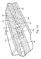
- FIGS. 13-14 are partial cross-section schematic views of needle and retention arm securement with a retention clip within a handle body, in accordance with embodiments of the present invention.
- FIG. 15 is a perspective view of a sling implant assembly, in accordance with embodiments of the present invention.
- FIG. 16 is an illustrative view of vaginal and abdominal surgical incision locations for a retropubic incontinence treatment procedure, in accordance with embodiments of the present invention.
- releasable needle systems 10 and methods are shown.
- Various embodiments of the system 10 can include a handle assembly 100 and a trocar needle 102 .
- embodiments of the handle assembly 100 can include a handle body portion 104 and a release sleeve 106 .
- the needle 102 can be curved, and includes a proximal end portion 102 a and a distal end portion 102 b .
- the proximal end 102 a includes a tip 108 that can be releasably secured in the handle assembly 102 as disclosed herein.
- the tip 108 can include one or more recesses, indents, protrusions, grooves or like features to facilitate securement and release of the needle 102 from the handle 104 .
- the tip 108 can include one or more circumferential indents, grooves or angled surfaces 108 a and a bulbous end portion 108 b .
- the proximal end portion 102 a can further include one or more recessed flats 108 c or like structures, with the one or more features 108 a provided intermediate the flat 108 c and the end portion 108 b .
- the tip 108 or other portions of the needle 102 can be constructed of metal or a composite material, or an injection molded plastic.
- the handle body 104 can be generally tapered or angled outward where the release sleeve 106 is selectively received.
- a pocket or recess portion 107 is adapted to mateably receive the sleeve 106 .
- the sleeve 106 can include a body portion 109 a and an elongate shaft portion 109 b , as demonstrated in FIGS. 1 and 5 .
- the elongate shaft portion 109 b can include a retention end arm feature 110 , and the body portion 109 a can be shaped and sized to mateably seat within the recess portion 107 of the handle body 104 .
- the end arm feature 110 of the sleeve 106 can include a distal tip 110 a and an aperture 110 b extending a distance into the distal tip 110 a . Further, an opening 110 c can be provided extending into a surface of the feature 110 and in fluid communication with the aperture 110 b , as shown in FIG. 5 .
- the handle body 104 includes a retention channel 112 adapted to receive the retention end feature 110 and the elongate shaft portion 109 b of the sleeve 106 , along a first length of the channel 112 extending in from the portion 107 , with the channel 112 further extending into and through the opposing end of the body 104 to define a needle channel 113 .
- the channel 112 can be larger at the end of the handle body 104 having the recess portion 107 and then narrow a distance within the body 104 .
- a portion of the channel 112 can include a retention clip 114 having opposing fingers 114 a , 114 b .
- the fingers 114 a , 114 b can include lips, protrusions, angled features and the like, and can be configured to extend inward within the channel 112 , as shown in FIG. 4 .
- operation of the handle assembly 102 can include inserting the needle tip 108 in an axial direction into the channel 113 of the handle body 104 ( FIG. 6 ). The axial movement continues until the tip 108 snaps into place within the confines of the fingers 114 a , 114 b of the retention clip 114 , as shown in FIG. 7 .
- the bulbous tip 108 b is pushed through the gap between the fingers 114 a , 114 b , causing the fingers to displace or deform a measurable amount and then snap or otherwise return to the initial opposing state once the bulbous tip 108 b is beyond the fingers 114 a , 114 b .
- This will selectively secure the needle tip 108 within the retention clip 114 .
- the release sleeve 106 is not shown in FIG. 7 to improve clarity of the depiction. However the sleeve would normally be present, as shown in FIG. 8 .
- the feature 110 of the sleeve 106 is inserted through the channel 112 to a position where the fingers 114 a , 114 b extend into the opening 110 c and the needle tip 108 extends into the aperture 110 b of the feature 110 for snapping engagement with the fingers 114 a , 114 b as described herein.
- the needle tip 108 generally cannot be pulled out unless it is released by an axial pull on the release sleeve 106 in a direction away from the needle.
- the sleeve 106 is pulled back away from the handle body 104 such that the fingers 114 a , 114 b are spread out, deformed or displaced as they slide out of or otherwise disengage from the opening 110 c of the feature 110 .
- the fingers 114 a , 114 b are separated a sufficient distance, their secure engagement with the tip 108 is correspondingly released enough to permit the needle 102 (e.g., tip 108 b ) to slide away or otherwise disengage from the securement of the clip 114 .
- the handle 104 can then be slid back away from the needle 102 , or the needle 102 can be slid or pulled away from the channel 113 , and the handle 104 in general.
- One or more components of the handle assembly 100 can be constructed of a plastic material and can be fabricated via injection molding or other processes. A two-shot process or overmolding with an elastomeric skin layer such as Santoprene can be performed without departing from the scope of the invention. Moreover, components or portions of the handle can be formed from metal or composite materials, or by using different manufacturing processes without departing from the invention scope.
- rotational stability of the needle 102 is maintained while it is secured in the handle assembly 100 .
- Minor angular play at the connector tip 102 a can translate to large, undesirable movement at the opposing distal end 102 b of the needle as it passes through the patient's tissues or is otherwise deployed or introduced. Such movement could result in misdirection of the distal tip 102 b .
- the one or more flat portions 108 c on the needle 102 mate with respectively-shaped features or surfaces in the channel 113 of the handle to enhance torsional stability, as shown in FIGS. 6-8 .
- the flat portions of the channel 113 and needle 108 c closely conform to one another and can slightly interfere.
- the tolerance could be +0.0005/ ⁇ 0.0010 inches (with + being interference).
- the clip feature 114 can comprise RTP 305 polycarbonate (PC), which is 30% glass filled.
- PC polycarbonate
- a tensile modulus of 1.20 ⁇ 10 6 psi, a tensile strength of 18000 psi and a flexural strength of 28500 psi can be achieved.
- the configuration and materials provide a retention system where a metal needle body 102 may bear the highest stress, but such loads are well below its yield strength. The deflection and stress on the body of the handle is minimal.
- initial introduction of the release sleeve 106 into the body 104 portion forces the fingers 114 a , 114 b to spread apart by a deflection of approximately 0.040 inches. This can be greater than the deflection required to release the needle 102 , so repeated insertion/releases of the needle 102 produces lower stresses.
- the upward force required to generate the 0.040 inch deflection of the fingers can be approximately three pound-foot. Assuming that the deflection to release the needle is no more than 0.025 inches in certain embodiments, the maximum deflection force per finger (e.g., 114 a or 114 b ) of the clip 114 can be about 1.88 pound-foot. If the pulling force is too large for finger grip actuation, then the load can be reduced by modifying the part (e.g., fingers 114 a , 114 b ) geometry or using a weaker resin material.
- a needle 122 can be secured in a handle 124 and then released by pressing a release actuator 125 , such as a button, thus displacing the needle 122 away from engagement with the handle 124 .
- a release actuator 125 such as a button
- the needle 122 can be curved, and includes a proximal end 122 a and a distal end 122 b .
- the proximal end 122 a includes a tip that can be releasably secured in the handle 124 as disclosed herein.
- the tip can include one or more recesses, indents, protrusions, grooves or like features to facilitate securement and release of the needle 122 from the handle 124 .
- the tip at the proximal end 122 a can include one or more circumferential indents, grooves or angled surfaces, and a bulbous end portion 128 .
- the proximal end 122 a can further include one or more recessed flats 130 to assist in preventing rotational movement of the needle 122 within the handle 124 .
- the end portion 128 or other portions of the needle 122 can be constructed of metal or a composite material, or of an injection molded or like polymer material.
- the handle 124 can include a release assembly 132 .
- the release assembly can include a release arm 134 , the actuator 125 , and a biasing member, such as a spring.
- the release arm 134 like the retention end feature 110 of other embodiments, is generally elongate and can include a distal retention tip 134 a and an aperture 134 b extending a distance into the distal tip 134 a . Further, an opening 134 c can be provided extending into a surface of the arm 134 and in fluid communication with the aperture 134 b.
- the handle 124 further includes a retention channel 140 adapted to receive the retention arm 134 , with the channel 140 further extending into and through the opposing end of the handle 124 to define a needle channel 142 .
- a portion of the channel 140 can include a retention clip 144 having opposing fingers 144 a , 144 b .
- the fingers 144 a , 144 b can include lips, protrusions, angled features and the like, and can be configured to extend inward within the channel 140 , as shown in FIG. 12 .
- operation of the handle 124 can include inserting the needle tip 122 a in an axial direction into the channel 142 of the handle 124 .
- the axial movement continues until the bulbous end 128 snaps into place or otherwise secures within the confines of the fingers 144 a , 144 b of the retention clip 144 ( FIG. 14 ).
- the bulbous tip 128 is pushed through the gap between the fingers 144 a , 144 b , causing the fingers to displace or deform a measurable amount and then snap or otherwise return to the initial opposing state once the bulbous tip 128 is beyond the fingers 144 a , 144 b .
- This will selectively secure the needle end 122 a within the retention clip 144 . While the needle end 122 a is being inserted, the retention arm 134 is already in place and engaged with the clip 144 , as described with other embodiments.
- the arm 134 is provided within and is adapted to traverse axially within the retention channel 140 , with the fingers 144 a , 144 b selectively extendable into the opening 134 c and the needle end 122 a extends into the aperture 134 b of the arm 134 for snapping engagement of the bulbous tip 128 with the fingers 144 a , 144 b as described herein.
- the needle end 122 a Once secured or locked in place, the needle end 122 a generally cannot be pulled out unless it is released by actuation or other engagement of the actuator 125 .
- the actuator 125 can be a button or like device with a top portion 150 and a bottom portion 152 , such that the spring generally biases it in the extended position away from the handle 124 .
- the bottom portion 152 can include one or more angled edges or surfaces 154 adapted to engage with the arm 134 .
- the arm 34 can include a ramp feature (e.g., angled surface) 135 ( FIG. 10 ), wherein depressing or otherwise actuating the button 125 causes the button 125 to move down such that the angled edge 154 of the bottom portion 152 engages with and slides down along the ramp feature 135 of the arm 134 .
- a sling assembly 200 is shown in FIG. 15 .
- the sling assembly 200 can include an elongate mesh implant 202 , such as a polypropylene monofilament mesh.
- the mesh implant 202 is approximately 1.1 cm wide by 50 cm in length.
- a tensioning suture 204 e.g., absorbable
- a pair of polymer or like sheaths 206 cover and protect the mesh implant 202 during deployment and placement.
- the sheaths 206 overlap at or proximate the center of the assembly 200 , as indicated by a center marking (e.g., blue) 208 .
- One or more connectors 210 are provided at the ends of the assembly 200 and are adapted to connect to ends of the various delivery needles of the present invention during the procedure.
- One or more additional marking (e.g., blue) 212 are provided near the end regions of the assembly 200 or sheaths 206 , identifying where to cut the sling assembly 200 to allow the sheaths 206 to be removed after placement of the mesh implant 202 .
- the following is an exemplary procedure for using the various releasable needle and handle systems disclosed herein with a retropubic sling assembly 200 to treat stress urinary stress incontinence or like pelvic disorders or conditions.
- the patient can be placed in a modified dorsal lithotomy position with hips flexed, legs elevated in stirrups and buttocks even with the edge of the table.
- the physician can identify and mark the two suprapubic exit points EP approximately 2 cm from the midline and just above the pubic symphysis ( FIG. 16 ).
- the mid-urethra is identified and two small transverse stab incisions are created approximately 0.5 cm at the marked suprapubic exit points.
- These exit sites should be close to the superior aspect of the pubic bone to avoid anatomic structures in the abdomen, inguinal area and lateral pelvic sidewall.
- the suprapubic incisions should be full thickness through the dermis in order to avoid excessive force while passing the delivery needles.
- a full thickness sagittal incision VI in the vaginal mucosa is created at the level of the mid-urethra approximately 1-2 cm in length, and then peri-urethral tunnels are created approximately 1-2 cm deep starting from the ipsilateral incision edge and aiming lateral towards the inferior edge of the pubic bone. This will create access for the delivery needles.
- the delivery needle is attached to the handle or handle assembly, as disclosed herein. While loading the delivery needle to the handle, the handle button and needle curvature should face upward. An audible “click” may be heard, indicating that the delivery needle is fully engaged in the handle.
- the sling assembly 200 can be placed.
- the tip of the delivery needle is inserted into the vaginal incision while opening the tunnel, by placing gentle outward traction on a clamp (e.g., Allis) or like device.
- the delivery needle should be guided gently with the non-dominant hand of the physician, and the needle tip can be advanced to puncture through the endopelvic fascia and into the retropubic space. Advancement of the delivery needle should be stopped when it punctures through the fascia.
- the physician can confirm with an index finger of the non-dominant hand that the needle tip is just past the inferior edge of the pubic bone.
- the handle can be lowered so the distal end of the delivery needle contacts the posterior surface of the pubic bone and the trajectory of the needle tip is redirected to the targeted suprapubic exit point EP. Advancement of the delivery needle can continue, following the posterior surface of the pubic bone with the distal end of the delivery needle until the needle tip exits through the suprapubic incision exit point EP. The needle tip should protrude through the suprapubic incision allowing sufficient length to grasp the needle with the non-dominant hand. The delivery needle can then be pulled up until the trailing connection end, which is protruding through the vagina, is only protruding 2-3 cm out of the vaginal incision. This can ensure that the first delivery needle does not interfere with the second delivery needle pass.
- the handle can then be disconnected from the delivery needle, as described with the various embodiments of the present invention (e.g., pressing release button 125 or pulling on release sleeve 106 ).
- the various above steps can be repeated for a second delivery needle on the contralateral side of the patient.
- the physician can attach one end of the sling assembly 202 to a needle connection end protruding from the vagina.
- the connector 210 is generally attached when an audible “click” is heard.
- the physician can orient the blue center markings 208 on the sheaths 206 facing outward, away from the urethra, and the second of the sling assembly connectors can be connected to the other needle connection end (e.g., second needle).
- the delivery needles and sling assembly 200 are pulled up through the suprapubic incisions EP one at a time. Once the sling assembly 200 exits the suprapubic region, the ends 210 can be secured with a clamp just below the level of the blue end markings 212 on the sheaths 206 . The delivery needles and connectors 210 are then cut away, leaving behind the clamps, by cutting the sling assembly 200 at the blue marking 212 at each end of the sheath. The physician will then pull up on the cut ends of the sling assembly 200 to position it under the mid-urethra in a generally tension-free manner.
- the blue markings 208 on the sheaths can be used to indicate the center of the sling and can be used for centering the sling under the mid-urethra. Once desired placement is achieved, the clamps can be removed. Then sheaths 206 can be removed from the sling assembly 200 by pulling up on both sheath 206 ends simultaneously (e.g., thereby pulling them away from the overlapped section at or near the marking 208 ), leaving the mesh sling 202 in place.
- a blunt instrument such as a clamp
- an instrument such as a clamp
- the sling 202 may then be rolled around the clamp to improve the grip, pulling up to tighten the sling as desired. If needed, this can be repeated on the contralateral side.
Landscapes
- Health & Medical Sciences (AREA)
- Life Sciences & Earth Sciences (AREA)
- Surgery (AREA)
- Animal Behavior & Ethology (AREA)
- General Health & Medical Sciences (AREA)
- Engineering & Computer Science (AREA)
- Biomedical Technology (AREA)
- Heart & Thoracic Surgery (AREA)
- Veterinary Medicine (AREA)
- Public Health (AREA)
- Urology & Nephrology (AREA)
- Nuclear Medicine, Radiotherapy & Molecular Imaging (AREA)
- Medical Informatics (AREA)
- Molecular Biology (AREA)
- Cardiology (AREA)
- Oral & Maxillofacial Surgery (AREA)
- Vascular Medicine (AREA)
- Transplantation (AREA)
- Pathology (AREA)
- Prostheses (AREA)
- Surgical Instruments (AREA)
- Infusion, Injection, And Reservoir Apparatuses (AREA)
Abstract
Description
Claims (21)
Priority Applications (1)
| Application Number | Priority Date | Filing Date | Title |
|---|---|---|---|
| US14/377,149 US9693801B2 (en) | 2012-02-13 | 2013-02-13 | Releasably securable needle and handle system and method |
Applications Claiming Priority (3)
| Application Number | Priority Date | Filing Date | Title |
|---|---|---|---|
| US201261598198P | 2012-02-13 | 2012-02-13 | |
| PCT/US2013/025920 WO2013123036A2 (en) | 2012-02-13 | 2013-02-13 | Releasably securable needle and handle system and method |
| US14/377,149 US9693801B2 (en) | 2012-02-13 | 2013-02-13 | Releasably securable needle and handle system and method |
Publications (2)
| Publication Number | Publication Date |
|---|---|
| US20140378757A1 US20140378757A1 (en) | 2014-12-25 |
| US9693801B2 true US9693801B2 (en) | 2017-07-04 |
Family
ID=48984882
Family Applications (1)
| Application Number | Title | Priority Date | Filing Date |
|---|---|---|---|
| US14/377,149 Active 2033-09-09 US9693801B2 (en) | 2012-02-13 | 2013-02-13 | Releasably securable needle and handle system and method |
Country Status (5)
| Country | Link |
|---|---|
| US (1) | US9693801B2 (en) |
| EP (1) | EP2814432B1 (en) |
| AU (2) | AU2013221647B2 (en) |
| HK (1) | HK1204761A1 (en) |
| WO (1) | WO2013123036A2 (en) |
Families Citing this family (2)
| Publication number | Priority date | Publication date | Assignee | Title |
|---|---|---|---|---|
| US11147540B2 (en) * | 2015-07-01 | 2021-10-19 | Minnetronix, Inc. | Introducer sheath and puncture tool for the introduction and placement of a catheter in tissue |
| US10888313B2 (en) * | 2015-07-31 | 2021-01-12 | Boston Scientific Scimed, Inc. | Reusable implant delivery devices |
Citations (2)
| Publication number | Priority date | Publication date | Assignee | Title |
|---|---|---|---|---|
| US20020099259A1 (en) * | 2001-01-23 | 2002-07-25 | Anderson Kimberly A. | Surgical instrument and method |
| US20040144395A1 (en) * | 2002-08-02 | 2004-07-29 | Evans Douglas G | Self-anchoring sling and introducer system |
Family Cites Families (20)
| Publication number | Priority date | Publication date | Assignee | Title |
|---|---|---|---|---|
| US6139563A (en) * | 1997-09-25 | 2000-10-31 | Allegiance Corporation | Surgical device with malleable shaft |
| US6382214B1 (en) | 1998-04-24 | 2002-05-07 | American Medical Systems, Inc. | Methods and apparatus for correction of urinary and gynecological pathologies including treatment of male incontinence and female cystocele |
| US7025063B2 (en) | 2000-09-07 | 2006-04-11 | Ams Research Corporation | Coated sling material |
| US20020147382A1 (en) | 2001-01-23 | 2002-10-10 | Neisz Johann J. | Surgical articles and methods |
| US6641525B2 (en) | 2001-01-23 | 2003-11-04 | Ams Research Corporation | Sling assembly with secure and convenient attachment |
| US6612977B2 (en) | 2001-01-23 | 2003-09-02 | American Medical Systems Inc. | Sling delivery system and method of use |
| US7407480B2 (en) | 2001-07-27 | 2008-08-05 | Ams Research Corporation | Method and apparatus for correction of urinary and gynecological pathologies, including treatment of incontinence cystocele |
| US6648921B2 (en) | 2001-10-03 | 2003-11-18 | Ams Research Corporation | Implantable article |
| US7303525B2 (en) | 2003-08-22 | 2007-12-04 | Ams Research Corporation | Surgical article and methods for treating female urinary incontinence |
| US7347812B2 (en) | 2003-09-22 | 2008-03-25 | Ams Research Corporation | Prolapse repair |
| US7500945B2 (en) | 2004-04-30 | 2009-03-10 | Ams Research Corporation | Method and apparatus for treating pelvic organ prolapse |
| US7351197B2 (en) | 2004-05-07 | 2008-04-01 | Ams Research Corporation | Method and apparatus for cystocele repair |
| WO2006108045A2 (en) | 2005-04-05 | 2006-10-12 | Ans Research Corporation | Articles, devices, and methods for pelvic surgery |
| WO2007097994A2 (en) | 2006-02-16 | 2007-08-30 | Ams Research Corporation | Surgical articles and methods for treating pelvic conditions |
| US20080004656A1 (en) * | 2006-04-28 | 2008-01-03 | Bovie Medical Corporation | Surgical instrument with detachable tool assembly |
| AU2007261550B2 (en) | 2006-06-16 | 2013-04-18 | Boston Scientific Scimed, Inc. | Surgical implants and tools for treating pelvic conditions |
| EP3045120A1 (en) | 2006-10-26 | 2016-07-20 | AMS Research Corporation | Surgical articles for treating pelvic conditions |
| CN101600402B (en) | 2006-10-26 | 2012-12-05 | Ams研究公司 | Surgical articles and methods for treating pelvic conditions |
| JP5599707B2 (en) | 2007-07-27 | 2014-10-01 | エーエムエス リサーチ コーポレイション | Pelvic floor treatment and related instruments and implants |
| CN102245111B (en) | 2008-10-27 | 2014-07-16 | Ams研究公司 | Surgical needle and anchor system with retractable features |
-
2013
- 2013-02-13 US US14/377,149 patent/US9693801B2/en active Active
- 2013-02-13 WO PCT/US2013/025920 patent/WO2013123036A2/en active Application Filing
- 2013-02-13 AU AU2013221647A patent/AU2013221647B2/en active Active
- 2013-02-13 EP EP13749644.4A patent/EP2814432B1/en active Active
-
2015
- 2015-06-04 HK HK15105343.6A patent/HK1204761A1/en unknown
-
2016
- 2016-12-29 AU AU2016277768A patent/AU2016277768B2/en active Active
Patent Citations (2)
| Publication number | Priority date | Publication date | Assignee | Title |
|---|---|---|---|---|
| US20020099259A1 (en) * | 2001-01-23 | 2002-07-25 | Anderson Kimberly A. | Surgical instrument and method |
| US20040144395A1 (en) * | 2002-08-02 | 2004-07-29 | Evans Douglas G | Self-anchoring sling and introducer system |
Also Published As
| Publication number | Publication date |
|---|---|
| AU2016277768B2 (en) | 2018-11-01 |
| WO2013123036A3 (en) | 2014-10-02 |
| EP2814432A2 (en) | 2014-12-24 |
| EP2814432B1 (en) | 2019-05-01 |
| AU2013221647B2 (en) | 2016-12-08 |
| WO2013123036A2 (en) | 2013-08-22 |
| US20140378757A1 (en) | 2014-12-25 |
| HK1204761A1 (en) | 2015-12-04 |
| AU2013221647A1 (en) | 2014-08-07 |
| EP2814432A4 (en) | 2015-10-21 |
| AU2016277768A1 (en) | 2017-01-19 |
Similar Documents
| Publication | Publication Date | Title |
|---|---|---|
| US10010394B2 (en) | Pelvic floor treatments and related tools and implants | |
| US9937029B2 (en) | Surgical articles and methods for treating pelvic conditions | |
| US8622886B2 (en) | Surgical instrument and method for the treatment of urinary incontinence | |
| CA2906243C (en) | Pelvic implant and delivery system | |
| EP2964146B1 (en) | Surgical instrument for the treatment of urinary incontinence | |
| AU2016277768B2 (en) | Releasably securable needle and handle system and method | |
| EP2854658B1 (en) | Implant insertion systems | |
| AU2015202172B2 (en) | Pelvic implant and delivery system | |
| AU2016203709B2 (en) | Pelvic floor treatments and related tools and implants | |
| AU2014202158B2 (en) | Pelvic floor treatments and related tools and implants |
Legal Events
| Date | Code | Title | Description |
|---|---|---|---|
| AS | Assignment |
Owner name: AMS RESEARCH CORPORATION, MINNESOTA Free format text: ASSIGNMENT OF ASSIGNORS INTEREST;ASSIGNOR:ALLEN, JOHN J.;REEL/FRAME:033480/0793 Effective date: 20140730 |
|
| AS | Assignment |
Owner name: AMS RESEARCH, LLC, MINNESOTA Free format text: CHANGE OF NAME;ASSIGNOR:AMS RESEARCH CORPATION;REEL/FRAME:037300/0199 Effective date: 20141217 |
|
| AS | Assignment |
Owner name: ASTORA WOMEN'S HEALTH, LLC, MINNESOTA Free format text: CHANGE OF NAME;ASSIGNOR:APHRODITE WOMEN'S HEALTH, LLC;REEL/FRAME:037473/0919 Effective date: 20150929 Owner name: APHRODITE WOMEN'S HEALTH, LLC, MINNESOTA Free format text: ASSIGNMENT OF ASSIGNORS INTEREST;ASSIGNOR:AMS RESEARCH, LLC;REEL/FRAME:037473/0745 Effective date: 20150227 |
|
| AS | Assignment |
Owner name: AMS RESEARCH, LLC, MINNESOTA Free format text: CORRECTIVE ASSIGNMENT TO CORRECT THE CONVEYING PARTY DATA; PREVIOUSLY RECORDED ON REEL 037300 FRAME 0199. ASSIGNOR(S) HEREBY CONFIRMS THE CHANGE OF NAME;ASSIGNOR:AMS RESEARCH CORPORATION;REEL/FRAME:037916/0028 Effective date: 20141217 |
|
| AS | Assignment |
Owner name: WILMINGTON TRUST, NATIONAL ASSOCIATION, AS COLLATERAL TRUSTEE, DELAWARE Free format text: SECURITY INTEREST;ASSIGNOR:ASTORA WOMEN'S HEALTH, LLC;REEL/FRAME:042743/0278 Effective date: 20170427 Owner name: WILMINGTON TRUST, NATIONAL ASSOCIATION, AS COLLATE Free format text: SECURITY INTEREST;ASSIGNOR:ASTORA WOMEN'S HEALTH, LLC;REEL/FRAME:042743/0278 Effective date: 20170427 |
|
| STCF | Information on status: patent grant |
Free format text: PATENTED CASE |
|
| AS | Assignment |
Owner name: BOSTON SCIENTIFIC CORPORATION, MASSACHUSETTS Free format text: ASSIGNMENT OF ASSIGNORS INTEREST;ASSIGNORS:ASTORA WOMEN'S HEALTH, LLC;ENDO HEALTH SOLUTIONS INC.;ASTORA WOMEN'S HEALTH HOLDINGS, LLC;REEL/FRAME:043777/0895 Effective date: 20161222 Owner name: BOSTON SCIENTIFIC SCIMED, INC., MINNESOTA Free format text: ASSIGNMENT OF ASSIGNORS INTEREST;ASSIGNOR:BOSTON SCIENTIFIC CORPORATION;REEL/FRAME:043778/0167 Effective date: 20161222 |
|
| MAFP | Maintenance fee payment |
Free format text: PAYMENT OF MAINTENANCE FEE, 4TH YEAR, LARGE ENTITY (ORIGINAL EVENT CODE: M1551); ENTITY STATUS OF PATENT OWNER: LARGE ENTITY Year of fee payment: 4 |